EP2811100A1 - Waterproof plate device - Google Patents
Waterproof plate device Download PDFInfo
- Publication number
- EP2811100A1 EP2811100A1 EP12867425.6A EP12867425A EP2811100A1 EP 2811100 A1 EP2811100 A1 EP 2811100A1 EP 12867425 A EP12867425 A EP 12867425A EP 2811100 A1 EP2811100 A1 EP 2811100A1
- Authority
- EP
- European Patent Office
- Prior art keywords
- water
- blocking board
- water collecting
- water blocking
- collecting bucket
- Prior art date
- Legal status (The legal status is an assumption and is not a legal conclusion. Google has not performed a legal analysis and makes no representation as to the accuracy of the status listed.)
- Withdrawn
Links
Images


Classifications
-
- E—FIXED CONSTRUCTIONS
- E05—LOCKS; KEYS; WINDOW OR DOOR FITTINGS; SAFES
- E05F—DEVICES FOR MOVING WINGS INTO OPEN OR CLOSED POSITION; CHECKS FOR WINGS; WING FITTINGS NOT OTHERWISE PROVIDED FOR, CONCERNED WITH THE FUNCTIONING OF THE WING
- E05F15/00—Power-operated mechanisms for wings
- E05F15/70—Power-operated mechanisms for wings with automatic actuation
- E05F15/72—Power-operated mechanisms for wings with automatic actuation responsive to emergency conditions, e.g. fire
-
- E—FIXED CONSTRUCTIONS
- E02—HYDRAULIC ENGINEERING; FOUNDATIONS; SOIL SHIFTING
- E02B—HYDRAULIC ENGINEERING
- E02B7/00—Barrages or weirs; Layout, construction, methods of, or devices for, making same
- E02B7/20—Movable barrages; Lock or dry-dock gates
- E02B7/205—Barrages controlled by the variations of the water level; automatically functioning barrages
-
- E—FIXED CONSTRUCTIONS
- E02—HYDRAULIC ENGINEERING; FOUNDATIONS; SOIL SHIFTING
- E02B—HYDRAULIC ENGINEERING
- E02B7/00—Barrages or weirs; Layout, construction, methods of, or devices for, making same
- E02B7/20—Movable barrages; Lock or dry-dock gates
- E02B7/22—Stop log dams; Emergency gates
-
- E—FIXED CONSTRUCTIONS
- E02—HYDRAULIC ENGINEERING; FOUNDATIONS; SOIL SHIFTING
- E02B—HYDRAULIC ENGINEERING
- E02B7/00—Barrages or weirs; Layout, construction, methods of, or devices for, making same
- E02B7/20—Movable barrages; Lock or dry-dock gates
- E02B7/26—Vertical-lift gates
- E02B7/36—Elevating mechanisms for vertical-lift gates
-
- E—FIXED CONSTRUCTIONS
- E04—BUILDING
- E04H—BUILDINGS OR LIKE STRUCTURES FOR PARTICULAR PURPOSES; SWIMMING OR SPLASH BATHS OR POOLS; MASTS; FENCING; TENTS OR CANOPIES, IN GENERAL
- E04H9/00—Buildings, groups of buildings or shelters adapted to withstand or provide protection against abnormal external influences, e.g. war-like action, earthquake or extreme climate
- E04H9/14—Buildings, groups of buildings or shelters adapted to withstand or provide protection against abnormal external influences, e.g. war-like action, earthquake or extreme climate against other dangerous influences, e.g. tornadoes, floods
-
- E—FIXED CONSTRUCTIONS
- E06—DOORS, WINDOWS, SHUTTERS, OR ROLLER BLINDS IN GENERAL; LADDERS
- E06B—FIXED OR MOVABLE CLOSURES FOR OPENINGS IN BUILDINGS, VEHICLES, FENCES OR LIKE ENCLOSURES IN GENERAL, e.g. DOORS, WINDOWS, BLINDS, GATES
- E06B11/00—Means for allowing passage through fences, barriers or the like, e.g. stiles
- E06B11/02—Gates; Doors
- E06B11/022—Gates; Doors characterised by the manner of movement
- E06B11/023—Gates; Doors characterised by the manner of movement where the gate opens within the plane of the gate
- E06B11/025—Gates; Doors characterised by the manner of movement where the gate opens within the plane of the gate vertically
-
- E—FIXED CONSTRUCTIONS
- E06—DOORS, WINDOWS, SHUTTERS, OR ROLLER BLINDS IN GENERAL; LADDERS
- E06B—FIXED OR MOVABLE CLOSURES FOR OPENINGS IN BUILDINGS, VEHICLES, FENCES OR LIKE ENCLOSURES IN GENERAL, e.g. DOORS, WINDOWS, BLINDS, GATES
- E06B9/00—Screening or protective devices for wall or similar openings, with or without operating or securing mechanisms; Closures of similar construction
- E06B9/02—Shutters, movable grilles, or other safety closing devices, e.g. against burglary
- E06B9/04—Shutters, movable grilles, or other safety closing devices, e.g. against burglary of wing type, e.g. revolving or sliding
-
- E—FIXED CONSTRUCTIONS
- E02—HYDRAULIC ENGINEERING; FOUNDATIONS; SOIL SHIFTING
- E02B—HYDRAULIC ENGINEERING
- E02B3/00—Engineering works in connection with control or use of streams, rivers, coasts, or other marine sites; Sealings or joints for engineering works in general
- E02B3/04—Structures or apparatus for, or methods of, protecting banks, coasts, or harbours
- E02B3/10—Dams; Dykes; Sluice ways or other structures for dykes, dams, or the like
- E02B3/102—Permanently installed raisable dykes
-
- E—FIXED CONSTRUCTIONS
- E04—BUILDING
- E04H—BUILDINGS OR LIKE STRUCTURES FOR PARTICULAR PURPOSES; SWIMMING OR SPLASH BATHS OR POOLS; MASTS; FENCING; TENTS OR CANOPIES, IN GENERAL
- E04H9/00—Buildings, groups of buildings or shelters adapted to withstand or provide protection against abnormal external influences, e.g. war-like action, earthquake or extreme climate
- E04H9/14—Buildings, groups of buildings or shelters adapted to withstand or provide protection against abnormal external influences, e.g. war-like action, earthquake or extreme climate against other dangerous influences, e.g. tornadoes, floods
- E04H9/145—Floods
-
- E—FIXED CONSTRUCTIONS
- E06—DOORS, WINDOWS, SHUTTERS, OR ROLLER BLINDS IN GENERAL; LADDERS
- E06B—FIXED OR MOVABLE CLOSURES FOR OPENINGS IN BUILDINGS, VEHICLES, FENCES OR LIKE ENCLOSURES IN GENERAL, e.g. DOORS, WINDOWS, BLINDS, GATES
- E06B9/00—Screening or protective devices for wall or similar openings, with or without operating or securing mechanisms; Closures of similar construction
- E06B2009/007—Flood panels
-
- Y—GENERAL TAGGING OF NEW TECHNOLOGICAL DEVELOPMENTS; GENERAL TAGGING OF CROSS-SECTIONAL TECHNOLOGIES SPANNING OVER SEVERAL SECTIONS OF THE IPC; TECHNICAL SUBJECTS COVERED BY FORMER USPC CROSS-REFERENCE ART COLLECTIONS [XRACs] AND DIGESTS
- Y02—TECHNOLOGIES OR APPLICATIONS FOR MITIGATION OR ADAPTATION AGAINST CLIMATE CHANGE
- Y02A—TECHNOLOGIES FOR ADAPTATION TO CLIMATE CHANGE
- Y02A10/00—TECHNOLOGIES FOR ADAPTATION TO CLIMATE CHANGE at coastal zones; at river basins
- Y02A10/11—Hard structures, e.g. dams, dykes or breakwaters
-
- Y—GENERAL TAGGING OF NEW TECHNOLOGICAL DEVELOPMENTS; GENERAL TAGGING OF CROSS-SECTIONAL TECHNOLOGIES SPANNING OVER SEVERAL SECTIONS OF THE IPC; TECHNICAL SUBJECTS COVERED BY FORMER USPC CROSS-REFERENCE ART COLLECTIONS [XRACs] AND DIGESTS
- Y02—TECHNOLOGIES OR APPLICATIONS FOR MITIGATION OR ADAPTATION AGAINST CLIMATE CHANGE
- Y02A—TECHNOLOGIES FOR ADAPTATION TO CLIMATE CHANGE
- Y02A10/00—TECHNOLOGIES FOR ADAPTATION TO CLIMATE CHANGE at coastal zones; at river basins
- Y02A10/30—Flood prevention; Flood or storm water management, e.g. using flood barriers
-
- Y—GENERAL TAGGING OF NEW TECHNOLOGICAL DEVELOPMENTS; GENERAL TAGGING OF CROSS-SECTIONAL TECHNOLOGIES SPANNING OVER SEVERAL SECTIONS OF THE IPC; TECHNICAL SUBJECTS COVERED BY FORMER USPC CROSS-REFERENCE ART COLLECTIONS [XRACs] AND DIGESTS
- Y02—TECHNOLOGIES OR APPLICATIONS FOR MITIGATION OR ADAPTATION AGAINST CLIMATE CHANGE
- Y02A—TECHNOLOGIES FOR ADAPTATION TO CLIMATE CHANGE
- Y02A50/00—TECHNOLOGIES FOR ADAPTATION TO CLIMATE CHANGE in human health protection, e.g. against extreme weather
Definitions
- the present invention relates to a water blocking board apparatus for preventing water from entering a building and the like from a passage.
- the water blocking board apparatus (flood preventing apparatus) described in Patent Document 1 has: a water collecting bucket which is disposed inside a water collecting pit being a groove dug from a road surface; and a water blocking board (flood preventing board) in a board shape which is arranged in an accommodating pit being a groove dug from another part on the road surface and is capable of projecting from and retracting into the accommodating pit.
- the water collecting bucket and the water blocking board are configured to pull each other by means of a lifting chain and a sprocket.
- the water blocking board is accommodated in the accommodating pit and balanced in a position that an upper end of the water blocking board is in line with the road surface.
- water accumulates in the water collecting bucket and the water collecting bucket descends due to the weight of the water; then, the water blocking board ascends in a manner being pulled up.
- the water blocking board ascends and thereby projects from the road surface so as to block part of the passage, and prevents further entry of water.
- Patent Document 1 Japanese Patent No. 4644734
- an object of the present invention is to provide a water blocking board apparatus which can improve reliability of the operation of a water blocking board.
- a first aspect of the present invention is a water blocking board apparatus (1, 101, 201) having: a water blocking board (16) which is configured to ascend from a road surface to block water in order to prevent water from entering a building and the like from a passage; a water blocking board accommodating pit (14) in a groove shape, the water blocking board accommodating pit being formed under the road surface so as to accommodate the water blocking board; a water collecting pit (13) in a groove shape, the water collecting pit being arranged in a passage where the water blocking board accommodating pit is formed, the water collecting pit being configured to allow water to flow thereinto upon flooding; a water collecting bucket (15) being a container which is disposed in the water collecting pit to accumulate water having flown into the water collecting pit and is configured to descend in the water collecting pit by a weight of the water accumulated in the water collecting bucket; and a transmission mechanism (31) which connects the water blocking board and the water collecting bucket with each other directly or via another component and converts a force for the water collecting bucket to descend into a force for the water blocking board to ascend
- a second aspect of the present invention is the water blocking board apparatus (1, 101) according to the first aspect, wherein two transmission mechanisms (31) are arranged in an opposing manner with the water blocking board (16) therebetween; and the device (40, 140, 140') for inhibiting inclination of the water collecting bucket prevents the water collecting bucket from inclining by synchronizing the two transmission mechanisms.
- a third aspect of the present invention is the water blocking board apparatus (1, 101) according to the first or second aspect, wherein two transmission mechanisms (31) are arranged in an opposing manner with the water blocking board (16) therebetween; each of the transmission mechanisms has a chain (32) which connects the water blocking board and the water collecting bucket (15) with each other, and a sprocket wheel (37) being a toothed wheel which is disposed at the water collecting bucket and engages the chain; and the device (40, 140, 140') for inhibiting inclination of the water collecting bucket has a connecting shaft bar (41) being a shaft which connects, directly or via another component, rotation axes of each sprocket wheel provided to the transmission mechanisms arranged in the opposing manner.
- a fourth aspect of the present invention is the water blocking board apparatus (1, 101) according to the third aspect, wherein the connecting shaft bar (41) is disposed below a ground even in a state where the water collecting bucket (15) has risen.
- the water collecting bucket is inhibited from inclining when descending in the water collecting pit, and therefore can descend smoothly. As such, the reliability of the operation of the water blocking board apparatus can be improved.
- Fig. 1 is a perspective view of a state in which the water blocking board apparatus 1 according to the first embodiment is disposed in a passage.
- Fig. 1A shows a state when a water blocking board 16 is accommodated in a water blocking board accommodating pit 14 (see Fig. 4 ) and when the passage is open.
- Fig. 1B shows a state when the water blocking board 16 is projecting from the water blocking board accommodating pit 14 to close part of the passage.
- Fig. 2 is a view of the water blocking board apparatus 1 seen in the direction shown by the arrow II of Fig. 1A , that is, seen from an entry side of the passage in the state when the passage is open.
- Fig. 3 is a view of the water blocking board apparatus 1 seen in the direction shown by the arrow III of Fig.
- FIG. 4 is a cross-sectional view of the water blocking board apparatus 1 taken along the vertical line shown by IV-IV of Fig. 2 and seen in the direction of the arrows.
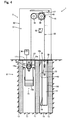
- Fig. 5 is a cross-sectional view of the water blocking board apparatus 1 taken along the vertical line shown by V-V of Fig. 3 and seen in the direction of the arrows.
- the water blocking board apparatus 1 will be described with reference to Figs. 1 to 5 and each view shown as appropriate.
- components are shown adequately in a penetrative manner for the illustration. In addition, some components are sometimes omitted in each view in order to make the view easy to see.
- Figs. 1A and 1B are views of the water blocking board apparatus 1 seen from the entry side of the passage. That is, in a case of flooding or the like, water enters from the entry side of the passage.
- the water blocking board apparatus 1 has a passage open-close part 2 and a mechanism accommodation part 3. As seen in Figs. 1 to 3 , the mechanism accommodation part 3 is arranged on both one end and the other end of the passage open-close part 2, so as to stand in an opposing manner. As is apparent from Figs. 1A and 1B , the water blocking board apparatus 1 is disposed in a passage that is formed between walls. More specifically, the passage open-close part 2 is buried in a road surface forming the passage, and the mechanism accommodation part 3 is disposed on/in each of the walls forming the passage. With this configuration, the passage is open at normal times, as shown in Fig. 1A and Fig. 2 , allowing passing therethrough.
- the water blocking board 16 ascends as shown in Fig. 3 to block part of the passage, thereby enabling prevention of further entry of water.
- the passage open-close part 2 and the mechanism accommodation part 3 will be described below in more detail.
- the passage open-close part 2 has: partitioning members 10, 11, 12; a water collecting bucket 15; a water blocking board 16; a lid member 17; members 18, 19 for pressing the water blocking board; and a sealing member 20. Since the passage open-close part 2 is buried in the road surface of the passage as described above, each member constituting the passage open-close part 2 is basically also buried therein, except for some components.
- the partitioning members 10, 11, 12 are board-shaped members which have a substantially rectangular cross section, as shown in Figs. 4 and 5 and extend in the right-and-left direction of the water blocking board apparatus 1 (right-and-left direction of the drawing sheets of Figs. 2 and 3 ; back-and-front direction of the drawing sheets of Figs. 4 and 5 ).
- the partitioning members 10, 11, 12 are aligned at predetermined intervals in the entry-and-exit direction of the passage (back-and-front direction of the drawing sheets of Figs. 2 and 3 ; right-and-left direction of the drawing sheets of Figs. 4 and 5 ), so that the board faces thereof face one another.
- the partitioning member 10, the partitioning member 11, and the partitioning member 12 are aligned in the mentioned order from the entry side to the exit side of the passage.
- a water collecting pit 13 is formed by a space between the partitioning member 10 and the partitioning member 11
- a water blocking board accommodating pit 14 is formed by a space between the partitioning member 11 and the partitioning member 12.
- the lid member 17 is arranged on an upper opening of the water collecting pit 13 in a manner to cover it, thereby forming a part of the surface of the passage.
- the lid member 17 is formed by grating and is configured to communicate the space above the ground with the water collecting pit 13 to let water flow into the water collecting pit 13.
- the water collecting bucket 15 is a container for accumulating water flowing into the water collecting pit 13. It has a cross section shown in Figs. 4 and 5 and extends in the right-and-left direction of the water blocking board apparatus 1 as shown in Figs. 2 and 3 .
- the water collecting bucket 15 is accommodated in the water collecting pit 13 and is capable of ascending and descending in the water collecting pit 13.
- the water collecting bucket 15 is formed slightly smaller than the water collecting pit 13 in the right-and-left direction of the water blocking board apparatus 1, and allows water to flow thereinto from its upper opening and to be accumulated therein.
- the water collecting bucket 15 has an entire height which is no more than a half of the depth of the water collecting pit 13, and is configured not to hit the bottom surface of the water collecting pit 13 at its lowest position in its upward and downward motion.
- a sealing member 15a is disposed on an upper end of the water collecting bucket 15. It is attached thereon so as to block a gap between the water collecting bucket 15 and an inner wall surface of the water collecting pit 13. This can prevent water from entering the gap between the water collecting bucket 15 and the water collecting pit 13 and accumulating in the water collecting pit 13.
- the water collecting bucket 15 has a weight 15b placed in a lower part thereof and is balanced with the water blocking board 16 as described below.
- the weight 15b can be placed or removed piece by piece so that the weight of the weight 15b can be adjusted.
- the water blocking board 16 is a thick-board-shaped member which is capable of blocking water by closing at least part of the passage in a raised position. It has a cross section shown in Figs. 4 and 5 , and extends in the right-and-left direction of the water blocking board apparatus 1 as shown by the dashed-dotted line in Figs. 2 and 3 .
- the water blocking board 16 has a water blocking board body 16a which serves to block water, and a lid member 16b made of a steel plate which is fixed to an upper end portion of the water blocking board body 16a to form a part of the passage.
- An inner part of the water blocking board body 16a is formed of a foam material panel which is light and strong, such as foamed polystyrene, and the entire surface of the foam material panel is covered with a thin plate material having corrosion resistance and strength, such as a stainless steel plate. Since, in this manner, the foam material panel which is light and has a small specific weight is used inside the water blocking board body 16a, the weight of the water blocking board 16 is reduced. Thereby, it is possible to reduce force needed to hang the water blocking board 16 so as to be able to raise and lower it as described below. Moreover, since the surface of the foam material panel is covered with a thin plate which is harder than the foam material panel, the foam material panel can be protected against damage.
- foam material panel for the water blocking board body 16a
- possibilities of using another material are not excluded.
- a honeycomb core material may also be employed. This can improve the strength.
- the lid member 16b is a plate-shaped member made of a steel plate which is fixed to an upper end portion of the water blocking board body 16a to form a part of the passage.
- a surface of the lid member 16b on the road surface side preferably has a plurality of protrusions formed thereon. Thereby, pedestrians or vehicles can be prevented from slipping.
- the steel plate employed for the lid member 16b is preferably formed of the same material as the thin plate material of the water blocking board body 16a described above.
- the water blocking board body 16a is disposed in the water blocking board accommodating pit 14 in a manner capable of projecting from and retracting into the water blocking board accommodating pit 14. That is, the water blocking board body 16a is arranged to be able to take the position in which it is accommodated entirely in the water blocking board accommodating pit 14 and take the position in which a part of it is accommodated in the water blocking board accommodating pit 14 and the other part of it is projected to the passage.
- the lid member 16b covers an opening of the water blocking board accommodating pit 14 in a manner to close the opening, in the state when the water blocking board body 16a is accommodated entirely in the water blocking board accommodating pit 14.
- the water blocking board 16 is formed to have a weight which is heavier than the total weight of the water collecting bucket 15, a device 40 for inhibiting inclination of the water collecting bucket and a moving sprocket 37 described below. Thereby, the water blocking board 16 can be accommodated properly in the water blocking board accommodating pit 14 at normal times, as described below.
- the member 18 for pressing the water blocking board is arranged on an upper part of a wall face of the water blocking board accommodating pit 14 on the entry side of the passage (the left side of the drawing sheets of Figs. 4 and 5 ).
- the member 18 for pressing the water blocking board has a portion inclined upward to the exit side of the passage (the right side of the drawing sheets of Figs. 4 and 5 ), as can be seen in Figs. 4 and 5 .
- the member 19 for pressing the water blocking board which corresponds to the member 18 for pressing the water blocking board is provided on a lower part of the water blocking board 16 on the entry side of the passage.
- the member 19 for pressing the water blocking board has an inclined portion as does the member 18 for pressing the water blocking board.
- sealing member 20 is arranged on an upper part of a wall face of the water blocking board accommodating pit 14 on the exit side of the passage.
- the member 18 for pressing the water blocking board and the member 19 for pressing the water blocking board are disposed in an overlapping manner, in the state when the water blocking board 16 has been raised as shown in Fig. 5 .
- the members 18, 19 for pressing the water blocking board press the water blocking board 16 toward the exit side of the passage by the effect of contact between the inclined portions of the members 18, 19 for pressing the water blocking board. Since the water blocking board 16 is pressed securely to the sealing member 20, water can be stopped more surely.
- a water drain device may be arranged at the bottom of the water collecting pit 13 and the water blocking board accommodating pit 14. This can inhibit accumulation of water in the pits.
- the water drain device it is preferable for the water drain device to have a backflow prevention valve to prevent water from flowing back into the water collecting pit or the water blocking board accommodating pit.
- the mechanism accommodation part 3 will be described next.
- the mechanism accommodation part 3 is arranged on both ends, in the right-and-left direction, of the passage open-close part 2, and is provided on/in the walls forming the passage, as described above. Accordingly, two mechanism accommodation parts 3 are arranged in an opposing manner with the passage open-close part 2 therebetween, as shown in Figs. 1 to 3 . Since the basic structures of the two mechanism accommodation parts 3 are the same, only one of them will be described herein.
- the mechanism accommodation part 3 has a housing 30 and a transmission mechanism 31 accommodated in the housing 30.
- the housing 30 is a member to form an outer shell of the mechanism accommodation part 3 and is configured in a box shape to thereby be able to include the transmission mechanism 31 thereinside. Accordingly, the housing 30 is formed to be hollow inside with board-shaped components combined, for example.
- the transmission mechanism 31 has a function to interlock the water collecting bucket 15 and the water blocking board 16 to associate the ascent and descent thereof with each other. That is, it is a mechanism to connect the water blocking board 16 and the water collecting bucket 15 to each other and convert a force for the water collecting bucket 15 to descend into a force for the water blocking board 16 to ascend.
- the transmission mechanism 31 has a lifting chain 32, a first guide sprocket 35, a second guide sprocket 36, a moving sprocket 37, a device 40 for inhibiting inclination of the water collecting bucket, a ratchet mechanism 45, and members 48, 49 for pressing the water blocking board.
- the lifting chain 32 functions as a force transmission member to transmit the force between the water collecting bucket 15 and the water blocking board 16 so as to interlock them.
- the lifting chain is shown by a simple broken line in the figures to make it easy to view.
- One end of the lifting chain 32 is fixed to the housing 30 by a fixation member 34. Therefore, the end portion fixed by the fixation member 34 is prohibited from moving.
- the other end of the lifting chain 32 is fixed to a side surface of the water blocking board 16 in the right-and-left direction thereof by a fixation member 33. Therefore, the other end of the lifting chain 32 moves up and down in conjunction with the ascent and descent of the water blocking board 16.
- a portion between both ends of the lifting chain 32 is engaged with the first guide sprocket 35, the second sprocket 36, and the moving sprocket 37, and is held inside the housing 30.
- the first guide sprocket 35 is a sprocket wheel having a plurality of teeth formed on an outer circumference thereof, the teeth being engageable with the lifting chain 32. Therefore, the first guide sprocket 35 is capable of rotating with the center thereof as an axis, and the axis is fixed to the housing 30 to be prohibited from moving. That is, the first guide sprocket 35 is disposed in a manner capable of rotating while being fixed to a predetermined position of the housing 30.
- the first guide sprocket 35 is arranged on an upper side of the water blocking board 16, and a height position of the first guide sprocket 35 (a position in the upper-and-lower direction of the drawing sheets of Figs. 4 and 5 ) is a position that allows the water blocking board 16 to be held by the lifting chain 32 even in the position of being raised to the highest.
- a position of the first guide sprocket 35 in the direction of the entry and exit side of the passage (a position in the right-and-left direction of the drawing sheets of Figs.
- the second guide sprocket 36 is a sprocket wheel having a plurality of teeth formed on an outer circumference thereof, the teeth being engageable with the lifting chain 32, as is the first guide sprocket 35. Therefore, the second guide sprocket 36 is capable of rotating with the center thereof as an axis, and the axis is fixed to the housing 30 to be prohibited from moving. That is, the second guide sprocket 36 is disposed in a manner capable of rotating while being fixed to a predetermined position of the housing 30.
- the second guide sprocket 36 is disposed closer to the entry side of the passage (the left side of the drawing sheets of Figs. 4 and 5 ) than the first guide sprocket 35 is, and a height position of the second guide sprocket 36 is substantially the same as that of the first guide sprocket 35.
- the moving sprocket 37 is a sprocket wheel having a plurality of teeth formed on an outer circumference thereof, the teeth being engageable with the lifting chain 32.
- the moving sprocket 37 is capable of rotating with the center thereof as an axis, and the axis is arranged at an end of the water collecting bucket 15 in the right-and-left direction of the passage open-close part 2 (an end in the right-and-left direction of the drawing sheets of Figs. 2 and 3 .).
- the moving sprocket 37 can also move up and down following the water collecting bucket 15.
- the lifting chain 32 is engaged with the first guide sprocket 35, the second guide sprocket 36, and the moving sprocket 37 described above, in the following manner.
- a portion of the lifting chain 32 between the end portion thereof on the entry side of the passage and the end portion thereof on the exit side of the passage is hung on an upper side of the first guide sprocket and the second guide sprocket.
- the moving sprocket 37 is fitted with the lifting chain 32 in a manner being put thereon in a position between the second guide sprocket 36 and the end portion of the lifting chain 32 on the entry side of the passage. That is, the water collecting bucket 15 is hung downward in a manner being hooked to the lifting chain 32 via the moving sprocket 37. Specific operation of these components will be described below in detail.
- the device 40 for inhibiting inclination of the water collecting bucket is a device to control the water collecting bucket 15 not to incline in the view shown in Figs. 2 and 3 when the water collecting bucket 15 ascends and descends.
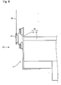
- Fig. 6 shows an enlarged view of the part shown by VI in Fig. 3 .
- Fig. 7 is a view seen in the direction shown by the arrow VII of Fig. 6 .
- the device 40 for preventing inclination of the water collecting bucket has a connecting shaft bar 41 and a bearing 42.
- the connecting shaft bar 41 is a so-called shaft in a bar shape. One end of the connecting shaft bar 41 is arranged on a rotation axis of one of the moving sprockets 37, and the other end of the connecting shaft bar 41 is arranged on a rotation axis of the other moving sprocket 37 (see Figs. 2 and 3 ) .
- the material or the cross-sectional shape of the connecting shaft bar 41 is not particularly limited as long as the connecting shaft bar 41 can function as a shaft. Examples of the connecting shaft bar 41 include hollow stainless round bars.
- the bearing 42 is for bearing the connecting shaft bar 41. It is placed between the water collecting bucket 15 and the moving sprocket 37, and is fixed to the water collecting bucket 15. It functions as a bearing with the connecting shaft bar 41 passed thereinto.
- the bearing 42 may be of any type as long as it enables smooth and stable rotation of the rotary shaft and is designed for that purpose, as in ordinary bearings. Examples thereof include commonly known bearings.
- the two moving sprockets 37 that are arranged on both sides in the right-and-left direction respectively, are connected to each other. Therefore, it is possible to synchronize the rotation of the two moving sprockets 37 and force them to rotate in the same manner. This can prevent inclination of the water collecting bucket 15 which is caused by the difference in the rotation speed of the two moving sprockets, as described below.
- the connecting shaft bar 41 is disposed lower than the lid member 17 . It is because the connecting shaft bar 41 would be an obstacle if it projected from the ground at normal times.
- the bearing 42 is disposed only on both ends of the connecting shaft bar 41, but is not limited to this configuration.
- a bearing may be further arranged along a longitudinal direction of the connecting shaft bar. This can inhibit the flexure of the connecting shaft bar.
- the ratchet mechanism 45 functions to prohibit the water blocking board from descending once it has ascended, and in the present embodiment it has a ratchet wheel 46 and a locking member 47.
- the ratchet mechanism 45 constitutes a so-called ratchet, and permits rotation of the first guide sprocket 35 in one direction and prohibits rotation thereof in the other direction.
- the ratchet wheel 46 is a toothed wheel for the ratchet, the wheel having a plurality of ratchet teeth which can be locked by the locking member 47, the plurality of ratchet teeth being formed on an outer circumference of the ratchet wheel 46.
- the ratchet wheel 46 is arranged coaxially on the first guide sprocket 35.
- the ratchet wheel 46 and the first guide sprocket 35 are fixed to each other so that they always move in tandem with each other.
- the locking member 47 has a locking protrusion which engages to stop the ratchet teeth of the ratchet wheel 46.
- the locking protrusion is in such a shape that it engages to stop the ratchet teeth of the ratchet wheel 46 so as to fulfill the function as a ratchet.
- the rotation in a direction in which the water blocking board 16 ascends is permitted by the ratchet mechanism 45, and the rotation in a direction in which the water blocking board 16 descends is prohibited by the ratchet mechanism 45. Since this prevents the water blocking board 16 from descending once it has ascended, the passage can be closed surely.
- the members 48, 49 for pressing the water blocking board form a pair together, and are block-shaped members that are formed such that faces thereof are oblique which contact each other when the water blocking board ascends and the members 48, 49 for pressing the water blocking board are disposed in a facing manner, as shown in Fig. 5 .
- the member 48 for pressing the water blocking board is fixed to the housing 30.
- the member 49 for pressing the water blocking board is fixed to a side face of the water blocking board 16 in the right-and-left direction.
- the member 49 for pressing the water blocking board is arranged on the fixation member 33. As seen in Fig.
- the members 48, 49 for pressing the water blocking board are arranged in a manner that the oblique faces thereof contact each other in the state that the water blocking board 16 has ascended. Thereby, the water blocking board 16 can be pressed to the exit side of the passage by the wedge effect, and the performance of stopping water by the water blocking board 16 can be improved.
- FIG. 8 shows views to illustrate the operation.
- Fig. 8A corresponds to Fig. 4
- Fig. 8B corresponds to Fig. 5 . That is, Fig. 8A shows the state in which the water blocking board 16 is at its lowest position and in which the water collecting bucket 15 is at its highest position. They take these respective positions at normal times.
- Fig. 8B shows the state in which the water blocking board 16 has ascended to block part of the passage and in which the water collecting bucket 15 is lowered. They take these respective positions in the case of flooding.
- many of the numeral references are omitted in Fig. 8 .
- Figs. 4 and 5 corresponding to Figs. 8A and 8B respectively, can be referred to.
- the water blocking board apparatus 1 is arranged, at normal times, such that the water collecting bucket 15 is disposed in the upper part of the water collecting pit 13 and that the water blocking board body 16a of the water blocking board 16 is entirely accommodated in the water blocking board accommodating pit 14. That is, since the motions of the water collecting bucket 15 and the water blocking board 16 are determined by the balance taken between them by their weight via the transmission mechanism 31, the balance between them is made by placing or removing the weight 15b of the water collecting bucket in order for them to take the position shown in Figs. 4 and 8A at normal times. In the condition shown in Fig. 8A , the passage is open, and therefore people, cars, and the like are not hindered from passing through the passage. Further, the water blocking board apparatus 1 is configured such that the lid members 16b and 17 do not cause unevenness on the road surface, therefore allowing comfortable passage.
- the motions of the water collecting bucket 15 and the water blocking board 16 are determined by the balance taken between them by their weight via the transmission mechanism 31; and when a predetermined amount or more of water is accumulated in the water collecting bucket 15 in the above manner, the total weight of the water collecting bucket 15, the moving sprocket 37, the device 40 for inhibiting inclination of the water collecting bucket, and the accumulated water is to become larger than the weight of the water blocking board 16. If the total weight thereof may not exceed the weight of the water blocking board 16, it is adjusted by the removable weight 15b in advance.
- the moving sprocket 37, the device 40 for inhibiting inclination of the water collecting bucket, and the accumulated water exceeds the weight of the water blocking board 16 due to the weight of the accumulated water, and the water collecting bucket 15 descends in the water collecting pit 13 as shown by VIIIb in Fig. 8A .
- the moving sprocket 37 descends substantially vertically together with the water collecting bucket 15 due to the descending force of the water collecting bucket 15, while rotating.
- the water collecting bucket 15 descends with the moving sprocket 37 rotating, and the water blocking board 16, following this, moves up as shown by VIIIc in Fig. 8A to rise to the passage gradually.
- the water blocking board 16 blocks water from entering the passage as shown in Fig. 8B .
- the transmission mechanism 31 as described above is configured to have the lifting chain 32 and the sprockets 35, 36, and 37, it is possible to pull up the water blocking board 16 with the lifting chain 32 engaged with each of the sprockets 35, 36, and 37 and inhibit wear or slippage between the lifting chain 32 and each of the sprockets 35, 36, and 37 caused by transmission of the ascending force to the water blocking board 16.
- the water blocking board 16 can be raised by the basic operation as described above. Since such operation does not require supply of electrical energy, reliable operation can be provided even in cases of unexpected heavy rains, floods, and the like, where the electricity is not used.
- the conventional water blocking board apparatus water flows in a lower direction if the water collecting bucket is inclined in the right-and-left direction (right-and-left direction of the drawing sheet in Fig. 2 ) for some reason, and in some cases further inclination is caused without correction of the inclination. If water accumulates in the water collecting bucket and the water collecting bucket starts to descend while inclined, the sprockets each disposed independently on both sides of the water collecting bucket descend separately while rotating. If there is a difference in the rotation angles of the sprockets, the lifting chains also move differently. Accordingly, the water collecting board connected to the lifting chains ascends differently between the right side and the left side thereof, causing inclination of the water blocking board.
- the water collecting bucket or the water blocking board hits the inner wall of the pit, preventing the water collecting bucket from descending properly. As such, the water blocking board is prevented from ascending. Even if the water blocking board does ascend, it ascends in an inclined manner in some cases.
- both of the transmission mechanisms 31 operate in the same manner. Thereby, the water collecting bucket 15 and the water blocking board 16 are prevented from ascending and descending in the inclined manner, leading to reliable operation thereof.
- Fig. 9 is a view focusing on a water collecting bucket 15, a moving sprocket 37, part of a lifting chain 32, and a device 140 for inhibiting inclination of the water collecting bucket of a water blocking board apparatus 101 according to a second embodiment, among the components provided to the water blocking board apparatus 101.
- Fig. 9 is a view of the water blocking board apparatus 101 seen in the same perspective as in Figs. 2 and 3 .
- the water blocking board apparatus 101 differs from the water blocking board apparatus 1 described above in that it employs the device 140 for inhibiting inclination of the water collecting bucket instead of the device 40 for inhibiting inclination of the water collecting bucket.
- the water blocking board apparatus 101 has the same components as those of the water blocking board apparatus 1. Descriptions of the same components will be omitted.
- the device 140 for inhibiting inclination of the water collecting bucket is one of the examples of inhibiting inclination of the water collecting bucket by synchronizing two moving sprockets opposing to each other, and has a connecting shaft bar 141, an auxiliary mechanism 142, and a bearing 42.
- the connecting shaft bar 141 is a so-called shaft in a bar shape.
- the auxiliary mechanism 142 is disposed on both ends of the connecting shaft bar 141, and the connecting shaft bar 141 is connected to two moving sprockets 37 via the auxiliary mechanism 142.
- the material and the cross-sectional shape of the connecting shaft bar 141 are not particularly limited as long as the connecting shaft bar 141 can function as a shaft. Examples thereof include hollow stainless round bars.
- the auxiliary mechanism 142 is disposed between the connecting shaft bar 141 and the moving sprocket 37. One end of the auxiliary mechanism 142 is connected to the connecting shaft bar 141 as described above, and the other end thereof is connected to the moving sprocket 37. At this time, the two moving sprockets 37, the connecting shaft bar 141, and the two auxiliary mechanisms 142 are connected in a manner capable of transmitting the rotary motions thereof to one another.
- a specific configuration of the auxiliary mechanism is not particularly limited as long as it can connect the two moving sprockets with the connecting shaft bar so as to transmit the rotary motions thereof to each other.
- the auxiliary mechanism 142 is capable of transmitting the rotary motion by means of two auxiliary shafts 142b and miter gears 142a arranged on end portions of the auxiliary shafts 142b and an end portion of the connecting shaft bar 141, respectively.
- the bearing 42 is for bearing the auxiliary shaft 142b of the auxiliary mechanism 142. It is disposed between the water collecting bucket 15 and the moving sprocket 37, and is fixed to the water collecting bucket 15. It functions as a bearing with the auxiliary shaft 142b passed thereinto.
- the bearing 42 may be of any type as long as it enables smooth and stable rotation of the rotary shaft and is designed for that purpose, as in ordinary bearings. Examples thereof include commonly known bearings.
- the two moving sprockets 37 arranged on both sides in the right-and-left direction respectively, are connected to each other by the connecting shaft bar 141 and the auxiliary mechanisms 142. Therefore, it is possible to synchronize the rotation of the two moving sprockets 37 and force them to rotate in the same manner. This can prevent inclination of the water collecting bucket 15 which is caused by the difference in the rotation speed of the two moving sprockets 37, as in the device 40 for inhibiting inclination of the water collecting bucket.
- the device 140 for inhibiting inclination of the water collecting bucket can have high flexibility in a position to dispose the connecting shaft bar 141.
- the auxiliary mechanism 142 can be made by the auxiliary mechanism 142 such that the connecting shaft bar 141 does not contact the pipe or the like.
- Fig. 10 is a view illustrating a device 140' for inhibiting inclination of the water collecting bucket, the device being a modification of the device 140 for inhibiting inclination of the water collecting bucket.
- Fig. 10 is a view of the device 140' for inhibiting inclination of the water collecting bucket seen in the same perspective as in Fig. 9 .
- the device 140' for inhibiting inclination of the water collecting bucket has an auxiliary mechanism 142' whose configuration differs from that of the auxiliary mechanism 142 described above.
- the auxiliary mechanism 142' is disposed between the moving sprocket 37 and the connecting shaft bar 141 while supported by the bearing 42, and has a first pulley 142a' , a second pulley 142b', a belt 142c', and an auxiliary shaft 142d'.
- the auxiliary shaft 142d' is fixed to the rotation axis of the moving sprocket 37.
- the first pulley 142a' is fixed to an end of the connecting shaft bar 141, and the second pulley 142b' is fixed to an end of the auxiliary shaft 142d' .
- the belt 142c' is arranged over the first pulley 142a' and the second pulley 142b'.
- the two moving sprockets 37 that are arranged on both sides in the right-and-left direction respectively, are connected with each other via the connecting shaft bar 141 and the auxiliary mechanisms 142'. Therefore, it is possible to synchronize the rotation of the two moving sprockets 37 and force them to rotate in the same manner. This can prevent inclination of the water collecting bucket 15 which is caused by the difference in the rotation speed of the two moving sprockets, as in the device 40 for inhibiting inclination of the water collecting bucket.
- the connecting shaft bars 41 and 141 employed in the devices for inhibiting inclination of the water collecting bucket may be configured as follows.
- the connecting shaft bars 41 and 141 may be formed of a flexible material, to be so-called flexible shafts. Thereby, when a pipe to let water flow into the water collecting pit 13 or a member to guide water is additionally arranged for example, the connecting shaft bar can be disposed in a bent manner so as to avoid the pipe or the like, allowing high flexibility in the arrangement of components.
- the connecting shaft bars 41 and 141 may also be configured to rotate in an eccentric manner.
- the centrifugal force is increased, enabling facilitation of the rotational force.
- the effect of increasing the rotation speed of the shaft and causing the shaft to rotate more works.
- force to operate the transmission mechanism can be given strongly even when there are some factors to prevent operation of the mechanism, such as degradation of sliding properties of the components provided to the transmission mechanism.
- Specific means to cause the eccentric rotation of the connecting shaft is not particularly limited, and any possible means commonly known may be adopted. For example, looking at the cross-sectional shape of the connecting shaft bar, configuring the connecting shaft bar so that a rotation center of the connecting shaft bar and a center of the gravity of the connecting shaft bar in its cross-sectional shape are displaced from each other, can be raised. As the degree of the positional displacement is larger, the eccentricity is larger.
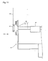
- one or more member(s) 41' for eccentricity which is(are) not concentric with the connecting shaft bar 41 may be arranged, as shown in Fig. 11 for example; the connecting shaft bar itself may be curved; or a curved portion may be formed on the connecting shaft bar itself.
- Fig. 12 shows a view of some components of a water blocking board apparatus 201 according to a third embodiment, the view corresponding to Fig. 6 .
- Fig. 12 is a view focusing on an end of a water collecting bucket 15 on one side in the right-and-left direction, a moving sprocket 37, part of a lifting chain 32, and one side of a device 240 for inhibiting inclination of the water collecting bucket.
- the water blocking board apparatus 201 has the same components on the other side as well in a manner that they oppose to each other.
- the water blocking board apparatus 201 differs from the water blocking board apparatus 1 described above in that it employs the device 240 for inhibiting inclination of the water collecting bucket instead of the device 40 for inhibiting inclination of the water collecting bucket. Other than this, the water blocking board apparatus 201 has the same components as those of the water blocking board apparatus 1. Descriptions of the same components will be omitted.
- the device 240 for inhibiting inclination of the water collecting bucket is one of the examples of inhibiting inclination of the water collecting bucket by directly restricting inclination of the water collecting bucket in the right-and-left direction, and has two guide rollers 241 and 242.
- the guide rollers 241 and 242 respectively have wheels 241a and 242a, and base materials 241b and 242b which hold the respective wheels 241a and 242b in a manner to enable rotation thereof.
- the guide roller 241 is fixed on an upper part of the face of the water collecting bucket 15 where the moving sprocket 37 is disposed. More specifically, the base material 241b is fixed to the water collecting bucket 15, and the wheel 241a is arranged to face an inner surface 13a of the water collecting pit.
- the guide roller 242 is fixed on a lower part of the face of the water collecting bucket 15 where the moving sprocket 37 is disposed. More specifically, the base material 242b is fixed to the water collecting bucket 15, and the wheel 242a is arranged to face the inner surface 13a of the water collecting pit.
- the wheels 241a and 242a do not necessarily have to contact the inner surface 13a of the water collecting pit at all times, but it is preferable for a gap between them to be small. Thereby, inclination of the water collecting bucket 15 can be prevented.
- the guide rollers 241 and 242 provided on both sides in the right-and-left direction are either contacted or positioned very closely to the inner surface 13a of the water collecting pit. Therefore, inclination of the water collecting bucket itself is restricted. At this time, since the guide rollers 241 and 242 contact the inner surface 13a of the water collecting pit by means of the wheels 241a and 242a respectively, the water collecting bucket 15 is not hindered from moving up and down.
Abstract
Description
- The present invention relates to a water blocking board apparatus for preventing water from entering a building and the like from a passage.
- When roads and the like are submerged in water during heavy rains or floods, the water also enters buildings, parking lots, and the like that are located therearound and causes further damage. In this case, if a means to prevent the entry of water is provided in passages leading to the buildings, the parking lots, and the like, the damage can be reduced. Based on this viewpoint, there is a water blocking board apparatus which is arranged in passages and can prevent entry of a given amount or more of water.
- Heretofore, various types of water blocking board apparatuses have been suggested, and a water blocking board apparatus as disclosed in
Patent Document 1 for example is one of them. The water blocking board apparatus (flood preventing apparatus) described inPatent Document 1 has: a water collecting bucket which is disposed inside a water collecting pit being a groove dug from a road surface; and a water blocking board (flood preventing board) in a board shape which is arranged in an accommodating pit being a groove dug from another part on the road surface and is capable of projecting from and retracting into the accommodating pit. The water collecting bucket and the water blocking board are configured to pull each other by means of a lifting chain and a sprocket. At normal times, the water blocking board is accommodated in the accommodating pit and balanced in a position that an upper end of the water blocking board is in line with the road surface. On the other hand, in a case of flooding or the like, water accumulates in the water collecting bucket and the water collecting bucket descends due to the weight of the water; then, the water blocking board ascends in a manner being pulled up. The water blocking board ascends and thereby projects from the road surface so as to block part of the passage, and prevents further entry of water. - Patent Document 1: Japanese Patent No.
4644734 - As already known, water has the characteristic to flow in a lower direction. Therefore, when the water collecting bucket of the water blocking board apparatus described in
Patent Document 1 is inclined, water flows toward a lower side of the water collecting bucket, and in some cases the inclination of the water collecting bucket is increased without being corrected. When the water collecting bucket tries to descend in the inclined state, it hits an inner wall of the water collecting pit and does not descend properly, therefore preventing the water blocking board from ascending, in some cases. Even if the water collecting bucket does descend, the water blocking board also ascends in an inclined manner as the water collecting bucket is inclined. - In view of the above problem, an object of the present invention is to provide a water blocking board apparatus which can improve reliability of the operation of a water blocking board.
- The present invention will be described hereinafter. The reference numerals given in accompanying drawings are shown in parentheses to make the present invention easy to understand, but the present invention is not limited to the embodiments shown in the drawings.
- A first aspect of the present invention is a water blocking board apparatus (1, 101, 201) having: a water blocking board (16) which is configured to ascend from a road surface to block water in order to prevent water from entering a building and the like from a passage; a water blocking board accommodating pit (14) in a groove shape, the water blocking board accommodating pit being formed under the road surface so as to accommodate the water blocking board; a water collecting pit (13) in a groove shape, the water collecting pit being arranged in a passage where the water blocking board accommodating pit is formed, the water collecting pit being configured to allow water to flow thereinto upon flooding; a water collecting bucket (15) being a container which is disposed in the water collecting pit to accumulate water having flown into the water collecting pit and is configured to descend in the water collecting pit by a weight of the water accumulated in the water collecting bucket; and a transmission mechanism (31) which connects the water blocking board and the water collecting bucket with each other directly or via another component and converts a force for the water collecting bucket to descend into a force for the water blocking board to ascend, wherein at least one of the transmission mechanism and the water collecting bucket is provided with a device (40, 140, 140', 240) for inhibiting inclination of the water collecting bucket which prevents the water collecting bucket from inclining.
- A second aspect of the present invention is the water blocking board apparatus (1, 101) according to the first aspect, wherein two transmission mechanisms (31) are arranged in an opposing manner with the water blocking board (16) therebetween; and the device (40, 140, 140') for inhibiting inclination of the water collecting bucket prevents the water collecting bucket from inclining by synchronizing the two transmission mechanisms.
- A third aspect of the present invention is the water blocking board apparatus (1, 101) according to the first or second aspect, wherein two transmission mechanisms (31) are arranged in an opposing manner with the water blocking board (16) therebetween; each of the transmission mechanisms has a chain (32) which connects the water blocking board and the water collecting bucket (15) with each other, and a sprocket wheel (37) being a toothed wheel which is disposed at the water collecting bucket and engages the chain; and the device (40, 140, 140') for inhibiting inclination of the water collecting bucket has a connecting shaft bar (41) being a shaft which connects, directly or via another component, rotation axes of each sprocket wheel provided to the transmission mechanisms arranged in the opposing manner.
- A fourth aspect of the present invention is the water blocking board apparatus (1, 101) according to the third aspect, wherein the connecting shaft bar (41) is disposed below a ground even in a state where the water collecting bucket (15) has risen.
- According to the present invention, the water collecting bucket is inhibited from inclining when descending in the water collecting pit, and therefore can descend smoothly. As such, the reliability of the operation of the water blocking board apparatus can be improved.
-
-
Fig. 1A is a perspective view of a passage where a water blocking board apparatus according to a first embodiment is disposed and shows a state in which the passage is open. -
Fig. 1B is a perspective view of the passage where the water blocking board apparatus according to the first embodiment is disposed and shows a state in which part of the passage is closed. -
Fig. 2 is a front view of the water blocking board apparatus seen in the direction shown by II ofFig. 1A . -
Fig. 3 is a front view of the water blocking board apparatus seen in the direction shown by III ofFig. 1B . -
Fig. 4 is a cross-sectional view taken along the line shown by IV-IV ofFig. 2 and seen in the direction of the arrows. -
Fig. 5 is a cross-sectional view taken along the line shown by V-V ofFig. 3 and seen in the direction of the arrows. -
Fig. 6 is an enlarged view of the part shown by VI ofFig. 3 . -
Fig. 7 is a view seen in the direction shown by the arrow VII ofFig. 6 . -
Fig. 8A is a view illustrating an operation of the water blocking board apparatus and shows an accommodated position of the water blocking board. -
Fig. 8B is a view illustrating the operation of the water blocking board apparatus and shows a projecting position of the water blocking board. -
Fig. 9 is a view illustrating adevice 140 for inhibiting inclination of a water collecting bucket of a water blocking board apparatus according to a second embodiment. -
Fig. 10 is a view illustrating a modification device 140' for inhibiting inclination of the water collecting bucket of the water blocking board apparatus according to the second embodiment. -
Fig. 11 is a view illustrating one example of eccentricity of a connecting shaft bar. -
Fig. 12 is a view illustrating adevice 240 for inhibiting inclination of a water collecting bucket of a water blocking board apparatus according to a third embodiment. - The functions and benefits of the present invention described above will be apparent from the following modes for carrying out the invention. The present invention will be described below based on the embodiments shown in the accompanying drawings, but is not limited to the embodiments.
-
Fig. 1 is a perspective view of a state in which the waterblocking board apparatus 1 according to the first embodiment is disposed in a passage.Fig. 1A shows a state when awater blocking board 16 is accommodated in a water blocking board accommodating pit 14 (seeFig. 4 ) and when the passage is open.Fig. 1B shows a state when thewater blocking board 16 is projecting from the water blockingboard accommodating pit 14 to close part of the passage.Fig. 2 is a view of the waterblocking board apparatus 1 seen in the direction shown by the arrow II ofFig. 1A , that is, seen from an entry side of the passage in the state when the passage is open.Fig. 3 is a view of the waterblocking board apparatus 1 seen in the direction shown by the arrow III ofFig. 1B , that is, seen from the entry side of the passage in the state when part of the passage is closed.Fig. 4 is a cross-sectional view of the waterblocking board apparatus 1 taken along the vertical line shown by IV-IV ofFig. 2 and seen in the direction of the arrows.Fig. 5 is a cross-sectional view of the waterblocking board apparatus 1 taken along the vertical line shown by V-V ofFig. 3 and seen in the direction of the arrows. The water blockingboard apparatus 1 will be described with reference toFigs. 1 to 5 and each view shown as appropriate. InFigs. 1 to 5 and each view that are referred to in the descriptions below, components are shown adequately in a penetrative manner for the illustration. In addition, some components are sometimes omitted in each view in order to make the view easy to see. - In the present embodiment, the entry side of the passage is on the lower side of
Figs. 1A and 1B which is shown obliquely from the left, and is on the left side of the drawing sheets ofFigs. 4 and5 ; and the exit side of the passage is on the opposite side. Accordingly,Figs. 2 and3 are views of the water blockingboard apparatus 1 seen from the entry side of the passage. That is, in a case of flooding or the like, water enters from the entry side of the passage. - The water blocking
board apparatus 1 has a passage open-close part 2 and amechanism accommodation part 3. As seen inFigs. 1 to 3 , themechanism accommodation part 3 is arranged on both one end and the other end of the passage open-close part 2, so as to stand in an opposing manner. As is apparent fromFigs. 1A and 1B , the water blockingboard apparatus 1 is disposed in a passage that is formed between walls. More specifically, the passage open-close part 2 is buried in a road surface forming the passage, and themechanism accommodation part 3 is disposed on/in each of the walls forming the passage. With this configuration, the passage is open at normal times, as shown inFig. 1A andFig. 2 , allowing passing therethrough. On the other hand, in a case of flooding or the like, thewater blocking board 16 ascends as shown inFig. 3 to block part of the passage, thereby enabling prevention of further entry of water. The passage open-close part 2 and themechanism accommodation part 3 will be described below in more detail. - As shown in
Figs. 2 to 5 , the passage open-close part 2 has: partitioningmembers water collecting bucket 15; awater blocking board 16; alid member 17;members member 20. Since the passage open-close part 2 is buried in the road surface of the passage as described above, each member constituting the passage open-close part 2 is basically also buried therein, except for some components. - The
partitioning members Figs. 4 and5 and extend in the right-and-left direction of the water blocking board apparatus 1 (right-and-left direction of the drawing sheets ofFigs. 2 and3 ; back-and-front direction of the drawing sheets ofFigs. 4 and5 ). Thepartitioning members Figs. 2 and3 ; right-and-left direction of the drawing sheets ofFigs. 4 and5 ), so that the board faces thereof face one another. In the present embodiment, the partitioningmember 10, the partitioningmember 11, and the partitioningmember 12 are aligned in the mentioned order from the entry side to the exit side of the passage. - Herein, a
water collecting pit 13 is formed by a space between the partitioningmember 10 and the partitioningmember 11, and a water blockingboard accommodating pit 14 is formed by a space between the partitioningmember 11 and the partitioningmember 12. - The
lid member 17 is arranged on an upper opening of thewater collecting pit 13 in a manner to cover it, thereby forming a part of the surface of the passage. Thelid member 17 is formed by grating and is configured to communicate the space above the ground with thewater collecting pit 13 to let water flow into thewater collecting pit 13. - The
water collecting bucket 15 is a container for accumulating water flowing into thewater collecting pit 13. It has a cross section shown inFigs. 4 and5 and extends in the right-and-left direction of the water blockingboard apparatus 1 as shown inFigs. 2 and3 . Thewater collecting bucket 15 is accommodated in thewater collecting pit 13 and is capable of ascending and descending in thewater collecting pit 13. In specific, thewater collecting bucket 15 is formed slightly smaller than thewater collecting pit 13 in the right-and-left direction of the water blockingboard apparatus 1, and allows water to flow thereinto from its upper opening and to be accumulated therein. - Preferably, the
water collecting bucket 15 has an entire height which is no more than a half of the depth of thewater collecting pit 13, and is configured not to hit the bottom surface of thewater collecting pit 13 at its lowest position in its upward and downward motion. - A sealing
member 15a is disposed on an upper end of thewater collecting bucket 15. It is attached thereon so as to block a gap between thewater collecting bucket 15 and an inner wall surface of thewater collecting pit 13. This can prevent water from entering the gap between thewater collecting bucket 15 and thewater collecting pit 13 and accumulating in thewater collecting pit 13. - Further, the
water collecting bucket 15 has aweight 15b placed in a lower part thereof and is balanced with thewater blocking board 16 as described below. Theweight 15b can be placed or removed piece by piece so that the weight of theweight 15b can be adjusted. - The
water blocking board 16 is a thick-board-shaped member which is capable of blocking water by closing at least part of the passage in a raised position. It has a cross section shown inFigs. 4 and5 , and extends in the right-and-left direction of the water blockingboard apparatus 1 as shown by the dashed-dotted line inFigs. 2 and3 . - The
water blocking board 16 has a water blockingboard body 16a which serves to block water, and alid member 16b made of a steel plate which is fixed to an upper end portion of the water blockingboard body 16a to form a part of the passage. - An inner part of the water blocking
board body 16a is formed of a foam material panel which is light and strong, such as foamed polystyrene, and the entire surface of the foam material panel is covered with a thin plate material having corrosion resistance and strength, such as a stainless steel plate. Since, in this manner, the foam material panel which is light and has a small specific weight is used inside the water blockingboard body 16a, the weight of thewater blocking board 16 is reduced. Thereby, it is possible to reduce force needed to hang thewater blocking board 16 so as to be able to raise and lower it as described below. Moreover, since the surface of the foam material panel is covered with a thin plate which is harder than the foam material panel, the foam material panel can be protected against damage. - Although an example of using the foam material panel for the water blocking
board body 16a is shown herein, possibilities of using another material are not excluded. For example, a honeycomb core material may also be employed. This can improve the strength. - The
lid member 16b is a plate-shaped member made of a steel plate which is fixed to an upper end portion of the water blockingboard body 16a to form a part of the passage. A surface of thelid member 16b on the road surface side preferably has a plurality of protrusions formed thereon. Thereby, pedestrians or vehicles can be prevented from slipping. The steel plate employed for thelid member 16b is preferably formed of the same material as the thin plate material of the water blockingboard body 16a described above. - Of the constituent elements of the
water blocking board 16 described above, the water blockingboard body 16a is disposed in the water blockingboard accommodating pit 14 in a manner capable of projecting from and retracting into the water blockingboard accommodating pit 14. That is, the water blockingboard body 16a is arranged to be able to take the position in which it is accommodated entirely in the water blockingboard accommodating pit 14 and take the position in which a part of it is accommodated in the water blockingboard accommodating pit 14 and the other part of it is projected to the passage. - In addition, the
lid member 16b covers an opening of the water blockingboard accommodating pit 14 in a manner to close the opening, in the state when the water blockingboard body 16a is accommodated entirely in the water blockingboard accommodating pit 14. - Herein, the
water blocking board 16 is formed to have a weight which is heavier than the total weight of thewater collecting bucket 15, adevice 40 for inhibiting inclination of the water collecting bucket and a movingsprocket 37 described below. Thereby, thewater blocking board 16 can be accommodated properly in the water blockingboard accommodating pit 14 at normal times, as described below. - As shown in
Figs. 4 and5 , themember 18 for pressing the water blocking board is arranged on an upper part of a wall face of the water blockingboard accommodating pit 14 on the entry side of the passage (the left side of the drawing sheets ofFigs. 4 and5 ). Themember 18 for pressing the water blocking board has a portion inclined upward to the exit side of the passage (the right side of the drawing sheets ofFigs. 4 and5 ), as can be seen inFigs. 4 and5 . - On the other hand, the
member 19 for pressing the water blocking board which corresponds to themember 18 for pressing the water blocking board is provided on a lower part of thewater blocking board 16 on the entry side of the passage. Themember 19 for pressing the water blocking board has an inclined portion as does themember 18 for pressing the water blocking board. - In addition, the sealing
member 20 is arranged on an upper part of a wall face of the water blockingboard accommodating pit 14 on the exit side of the passage. - According to the
members member 20 configured in this manner, themember 18 for pressing the water blocking board and themember 19 for pressing the water blocking board are disposed in an overlapping manner, in the state when thewater blocking board 16 has been raised as shown inFig. 5 . At this time, themembers water blocking board 16 toward the exit side of the passage by the effect of contact between the inclined portions of themembers water blocking board 16 is pressed securely to the sealingmember 20, water can be stopped more surely. - Herein, a water drain device may be arranged at the bottom of the
water collecting pit 13 and the water blockingboard accommodating pit 14. This can inhibit accumulation of water in the pits. In this case, it is preferable for the water drain device to have a backflow prevention valve to prevent water from flowing back into the water collecting pit or the water blocking board accommodating pit. - The
mechanism accommodation part 3 will be described next. Themechanism accommodation part 3 is arranged on both ends, in the right-and-left direction, of the passage open-close part 2, and is provided on/in the walls forming the passage, as described above. Accordingly, twomechanism accommodation parts 3 are arranged in an opposing manner with the passage open-close part 2 therebetween, as shown inFigs. 1 to 3 . Since the basic structures of the twomechanism accommodation parts 3 are the same, only one of them will be described herein. - The
mechanism accommodation part 3 has ahousing 30 and atransmission mechanism 31 accommodated in thehousing 30. - The
housing 30 is a member to form an outer shell of themechanism accommodation part 3 and is configured in a box shape to thereby be able to include thetransmission mechanism 31 thereinside. Accordingly, thehousing 30 is formed to be hollow inside with board-shaped components combined, for example. - The
transmission mechanism 31 has a function to interlock thewater collecting bucket 15 and thewater blocking board 16 to associate the ascent and descent thereof with each other. That is, it is a mechanism to connect thewater blocking board 16 and thewater collecting bucket 15 to each other and convert a force for thewater collecting bucket 15 to descend into a force for thewater blocking board 16 to ascend. As such, thetransmission mechanism 31 has a liftingchain 32, afirst guide sprocket 35, asecond guide sprocket 36, a movingsprocket 37, adevice 40 for inhibiting inclination of the water collecting bucket, aratchet mechanism 45, andmembers - The lifting
chain 32 functions as a force transmission member to transmit the force between thewater collecting bucket 15 and thewater blocking board 16 so as to interlock them. The lifting chain is shown by a simple broken line in the figures to make it easy to view. One end of the liftingchain 32 is fixed to thehousing 30 by afixation member 34. Therefore, the end portion fixed by thefixation member 34 is prohibited from moving. On the other hand, the other end of the liftingchain 32 is fixed to a side surface of thewater blocking board 16 in the right-and-left direction thereof by afixation member 33. Therefore, the other end of the liftingchain 32 moves up and down in conjunction with the ascent and descent of thewater blocking board 16. - Further, a portion between both ends of the lifting
chain 32 is engaged with thefirst guide sprocket 35, thesecond sprocket 36, and the movingsprocket 37, and is held inside thehousing 30. - The
first guide sprocket 35 is a sprocket wheel having a plurality of teeth formed on an outer circumference thereof, the teeth being engageable with the liftingchain 32. Therefore, thefirst guide sprocket 35 is capable of rotating with the center thereof as an axis, and the axis is fixed to thehousing 30 to be prohibited from moving. That is, thefirst guide sprocket 35 is disposed in a manner capable of rotating while being fixed to a predetermined position of thehousing 30. - The
first guide sprocket 35 is arranged on an upper side of thewater blocking board 16, and a height position of the first guide sprocket 35 (a position in the upper-and-lower direction of the drawing sheets ofFigs. 4 and5 ) is a position that allows thewater blocking board 16 to be held by the liftingchain 32 even in the position of being raised to the highest. On the other hand, a position of thefirst guide sprocket 35 in the direction of the entry and exit side of the passage (a position in the right-and-left direction of the drawing sheets ofFigs. 4 and5 ) is not particularly limited, but a configuration is preferred in which one end side of the liftingchain 32 extends vertically downward from a side of thefirst guide sprocket 35 on the exit side of the passage (the right side of the drawing sheets ofFigs. 4 and5 ) and the end is fixed to thewater blocking board 16. This makes it possible to pull thewater blocking board 16 straight up and move up and down thewater blocking board 16 more smoothly. - The
second guide sprocket 36 is a sprocket wheel having a plurality of teeth formed on an outer circumference thereof, the teeth being engageable with the liftingchain 32, as is thefirst guide sprocket 35. Therefore, thesecond guide sprocket 36 is capable of rotating with the center thereof as an axis, and the axis is fixed to thehousing 30 to be prohibited from moving. That is, thesecond guide sprocket 36 is disposed in a manner capable of rotating while being fixed to a predetermined position of thehousing 30. - The
second guide sprocket 36 is disposed closer to the entry side of the passage (the left side of the drawing sheets ofFigs. 4 and5 ) than thefirst guide sprocket 35 is, and a height position of thesecond guide sprocket 36 is substantially the same as that of thefirst guide sprocket 35. - The moving
sprocket 37 is a sprocket wheel having a plurality of teeth formed on an outer circumference thereof, the teeth being engageable with the liftingchain 32. The movingsprocket 37 is capable of rotating with the center thereof as an axis, and the axis is arranged at an end of thewater collecting bucket 15 in the right-and-left direction of the passage open-close part 2 (an end in the right-and-left direction of the drawing sheets ofFigs. 2 and3 .). - Since the
water collecting bucket 15 is arranged to be able to move upward and downward as described above, the movingsprocket 37 can also move up and down following thewater collecting bucket 15. - The lifting
chain 32 is engaged with thefirst guide sprocket 35, thesecond guide sprocket 36, and the movingsprocket 37 described above, in the following manner. A portion of the liftingchain 32 between the end portion thereof on the entry side of the passage and the end portion thereof on the exit side of the passage is hung on an upper side of the first guide sprocket and the second guide sprocket. On the other hand, the movingsprocket 37 is fitted with the liftingchain 32 in a manner being put thereon in a position between thesecond guide sprocket 36 and the end portion of the liftingchain 32 on the entry side of the passage. That is, thewater collecting bucket 15 is hung downward in a manner being hooked to the liftingchain 32 via the movingsprocket 37. Specific operation of these components will be described below in detail. - The
device 40 for inhibiting inclination of the water collecting bucket is a device to control thewater collecting bucket 15 not to incline in the view shown inFigs. 2 and3 when thewater collecting bucket 15 ascends and descends. In the present embodiment, an example of inhibiting the inclination by synchronizing two moving sprockets opposing to each other will be shown.Fig. 6 shows an enlarged view of the part shown by VI inFig. 3 .Fig. 7 is a view seen in the direction shown by the arrow VII ofFig. 6 . - The
device 40 for preventing inclination of the water collecting bucket has a connectingshaft bar 41 and abearing 42. - The connecting
shaft bar 41 is a so-called shaft in a bar shape. One end of the connectingshaft bar 41 is arranged on a rotation axis of one of the movingsprockets 37, and the other end of the connectingshaft bar 41 is arranged on a rotation axis of the other moving sprocket 37 (seeFigs. 2 and3 ) . The material or the cross-sectional shape of the connectingshaft bar 41 is not particularly limited as long as the connectingshaft bar 41 can function as a shaft. Examples of the connectingshaft bar 41 include hollow stainless round bars. - The
bearing 42 is for bearing the connectingshaft bar 41. It is placed between thewater collecting bucket 15 and the movingsprocket 37, and is fixed to thewater collecting bucket 15. It functions as a bearing with the connectingshaft bar 41 passed thereinto. Thebearing 42 may be of any type as long as it enables smooth and stable rotation of the rotary shaft and is designed for that purpose, as in ordinary bearings. Examples thereof include commonly known bearings. - With the
device 40 for inhibiting inclination of the water collecting bucket described above, the two movingsprockets 37 that are arranged on both sides in the right-and-left direction respectively, are connected to each other. Therefore, it is possible to synchronize the rotation of the two movingsprockets 37 and force them to rotate in the same manner. This can prevent inclination of thewater collecting bucket 15 which is caused by the difference in the rotation speed of the two moving sprockets, as described below. - Herein, when the
water collecting bucket 15 is disposed at its upper limit position in the condition of the water blockingboard apparatus 1 at normal times as shown inFig. 4 , the connectingshaft bar 41 is disposed lower than thelid member 17 . It is because the connectingshaft bar 41 would be an obstacle if it projected from the ground at normal times. - In the present embodiment, the
bearing 42 is disposed only on both ends of the connectingshaft bar 41, but is not limited to this configuration. A bearing may be further arranged along a longitudinal direction of the connecting shaft bar. This can inhibit the flexure of the connecting shaft bar. - Back to
Figs. 2 to 5 , description of the water blockingboard apparatus 1 will be continued. - The
ratchet mechanism 45 functions to prohibit the water blocking board from descending once it has ascended, and in the present embodiment it has aratchet wheel 46 and a lockingmember 47. Theratchet mechanism 45 constitutes a so-called ratchet, and permits rotation of thefirst guide sprocket 35 in one direction and prohibits rotation thereof in the other direction. - The
ratchet wheel 46 is a toothed wheel for the ratchet, the wheel having a plurality of ratchet teeth which can be locked by the lockingmember 47, the plurality of ratchet teeth being formed on an outer circumference of theratchet wheel 46. Theratchet wheel 46 is arranged coaxially on thefirst guide sprocket 35. Theratchet wheel 46 and thefirst guide sprocket 35 are fixed to each other so that they always move in tandem with each other. - The locking
member 47 has a locking protrusion which engages to stop the ratchet teeth of theratchet wheel 46. The locking protrusion is in such a shape that it engages to stop the ratchet teeth of theratchet wheel 46 so as to fulfill the function as a ratchet. - Of the rotations of the
first guide sprocket 35, the rotation in a direction in which thewater blocking board 16 ascends is permitted by theratchet mechanism 45, and the rotation in a direction in which thewater blocking board 16 descends is prohibited by theratchet mechanism 45. Since this prevents thewater blocking board 16 from descending once it has ascended, the passage can be closed surely. - The
members members Fig. 5 . Themember 48 for pressing the water blocking board is fixed to thehousing 30. On the other hand, themember 49 for pressing the water blocking board is fixed to a side face of thewater blocking board 16 in the right-and-left direction. In the present embodiment, themember 49 for pressing the water blocking board is arranged on thefixation member 33. As seen inFig. 5 , themembers water blocking board 16 has ascended. Thereby, thewater blocking board 16 can be pressed to the exit side of the passage by the wedge effect, and the performance of stopping water by thewater blocking board 16 can be improved. - Next, the operation of the water blocking
board apparatus 1 configured as above will be explained.Fig. 8 shows views to illustrate the operation.Fig. 8A corresponds toFig. 4 , andFig. 8B corresponds toFig. 5 . That is,Fig. 8A shows the state in which thewater blocking board 16 is at its lowest position and in which thewater collecting bucket 15 is at its highest position. They take these respective positions at normal times. On the other hand,Fig. 8B shows the state in which thewater blocking board 16 has ascended to block part of the passage and in which thewater collecting bucket 15 is lowered. They take these respective positions in the case of flooding. In order to prioritize the viewability ofFig. 8 , many of the numeral references are omitted inFig. 8 . For the numeral references,Figs. 4 and5 corresponding toFigs. 8A and 8B respectively, can be referred to. - As shown in
Fig. 8A , the water blockingboard apparatus 1 is arranged, at normal times, such that thewater collecting bucket 15 is disposed in the upper part of thewater collecting pit 13 and that the water blockingboard body 16a of thewater blocking board 16 is entirely accommodated in the water blockingboard accommodating pit 14. That is, since the motions of thewater collecting bucket 15 and thewater blocking board 16 are determined by the balance taken between them by their weight via thetransmission mechanism 31, the balance between them is made by placing or removing theweight 15b of the water collecting bucket in order for them to take the position shown inFigs. 4 and8A at normal times. In the condition shown inFig. 8A , the passage is open, and therefore people, cars, and the like are not hindered from passing through the passage. Further, the water blockingboard apparatus 1 is configured such that thelid members - On the other hand, if water starts to accumulate on the road surface due to a flood or the like, the water flows into the
water collecting pit 13 through thelid member 17 formed by grating, as shown by VIIIa inFig. 8A , and starts to accumulate in thewater collecting bucket 15. Then, if the water continues to flow into thewater collecting pit 13 in this manner, it accumulates in thewater collecting bucket 15 sequentially. - As described above, the motions of the
water collecting bucket 15 and thewater blocking board 16 are determined by the balance taken between them by their weight via thetransmission mechanism 31; and when a predetermined amount or more of water is accumulated in thewater collecting bucket 15 in the above manner, the total weight of thewater collecting bucket 15, the movingsprocket 37, thedevice 40 for inhibiting inclination of the water collecting bucket, and the accumulated water is to become larger than the weight of thewater blocking board 16. If the total weight thereof may not exceed the weight of thewater blocking board 16, it is adjusted by theremovable weight 15b in advance. Thereby, when the water that has flown and accumulated in thewater collecting bucket 15 reaches a predetermined weight, the total weight of thewater collecting bucket 15, the movingsprocket 37, thedevice 40 for inhibiting inclination of the water collecting bucket, and the accumulated water exceeds the weight of thewater blocking board 16 due to the weight of the accumulated water, and thewater collecting bucket 15 descends in thewater collecting pit 13 as shown by VIIIb inFig. 8A . Then, the movingsprocket 37 descends substantially vertically together with thewater collecting bucket 15 due to the descending force of thewater collecting bucket 15, while rotating. - In this manner, the
water collecting bucket 15 descends with the movingsprocket 37 rotating, and thewater blocking board 16, following this, moves up as shown by VIIIc inFig. 8A to rise to the passage gradually. As a result, thewater blocking board 16 blocks water from entering the passage as shown inFig. 8B . - Since the
transmission mechanism 31 as described above is configured to have the liftingchain 32 and thesprockets water blocking board 16 with the liftingchain 32 engaged with each of thesprockets chain 32 and each of thesprockets water blocking board 16. - The
water blocking board 16 can be raised by the basic operation as described above. Since such operation does not require supply of electrical energy, reliable operation can be provided even in cases of unexpected heavy rains, floods, and the like, where the electricity is not used. - On the other hand, in the conventional water blocking board apparatus, water flows in a lower direction if the water collecting bucket is inclined in the right-and-left direction (right-and-left direction of the drawing sheet in
Fig. 2 ) for some reason, and in some cases further inclination is caused without correction of the inclination. If water accumulates in the water collecting bucket and the water collecting bucket starts to descend while inclined, the sprockets each disposed independently on both sides of the water collecting bucket descend separately while rotating. If there is a difference in the rotation angles of the sprockets, the lifting chains also move differently. Accordingly, the water collecting board connected to the lifting chains ascends differently between the right side and the left side thereof, causing inclination of the water blocking board. Then, the water collecting bucket or the water blocking board hits the inner wall of the pit, preventing the water collecting bucket from descending properly. As such, the water blocking board is prevented from ascending. Even if the water blocking board does ascend, it ascends in an inclined manner in some cases. - By contrast, according to the water blocking
board apparatus 1 of the present embodiment, since thedevice 40 for inhibiting inclination of the water collecting bucket forces the two movingsprockets 37 to rotate in the same manner, both of thetransmission mechanisms 31 operate in the same manner. Thereby, thewater collecting bucket 15 and thewater blocking board 16 are prevented from ascending and descending in the inclined manner, leading to reliable operation thereof. -
Fig. 9 is a view focusing on awater collecting bucket 15, a movingsprocket 37, part of a liftingchain 32, and adevice 140 for inhibiting inclination of the water collecting bucket of a water blockingboard apparatus 101 according to a second embodiment, among the components provided to the water blockingboard apparatus 101.Fig. 9 is a view of the water blockingboard apparatus 101 seen in the same perspective as inFigs. 2 and3 . The water blockingboard apparatus 101 differs from the water blockingboard apparatus 1 described above in that it employs thedevice 140 for inhibiting inclination of the water collecting bucket instead of thedevice 40 for inhibiting inclination of the water collecting bucket. Other than this, the water blockingboard apparatus 101 has the same components as those of the water blockingboard apparatus 1. Descriptions of the same components will be omitted. - The
device 140 for inhibiting inclination of the water collecting bucket is one of the examples of inhibiting inclination of the water collecting bucket by synchronizing two moving sprockets opposing to each other, and has a connectingshaft bar 141, anauxiliary mechanism 142, and abearing 42. - The connecting
shaft bar 141 is a so-called shaft in a bar shape. Theauxiliary mechanism 142 is disposed on both ends of the connectingshaft bar 141, and the connectingshaft bar 141 is connected to two movingsprockets 37 via theauxiliary mechanism 142. The material and the cross-sectional shape of the connectingshaft bar 141 are not particularly limited as long as the connectingshaft bar 141 can function as a shaft. Examples thereof include hollow stainless round bars. - The
auxiliary mechanism 142 is disposed between the connectingshaft bar 141 and the movingsprocket 37. One end of theauxiliary mechanism 142 is connected to the connectingshaft bar 141 as described above, and the other end thereof is connected to the movingsprocket 37. At this time, the two movingsprockets 37, the connectingshaft bar 141, and the twoauxiliary mechanisms 142 are connected in a manner capable of transmitting the rotary motions thereof to one another. - A specific configuration of the auxiliary mechanism is not particularly limited as long as it can connect the two moving sprockets with the connecting shaft bar so as to transmit the rotary motions thereof to each other. In the present embodiment, as seen in
Fig. 9 , theauxiliary mechanism 142 is capable of transmitting the rotary motion by means of twoauxiliary shafts 142b andmiter gears 142a arranged on end portions of theauxiliary shafts 142b and an end portion of the connectingshaft bar 141, respectively. - The
bearing 42 is for bearing theauxiliary shaft 142b of theauxiliary mechanism 142. It is disposed between thewater collecting bucket 15 and the movingsprocket 37, and is fixed to thewater collecting bucket 15. It functions as a bearing with theauxiliary shaft 142b passed thereinto. Thebearing 42 may be of any type as long as it enables smooth and stable rotation of the rotary shaft and is designed for that purpose, as in ordinary bearings. Examples thereof include commonly known bearings. - With the
device 140 for inhibiting inclination of the water collecting bucket configured as above, the two movingsprockets 37 arranged on both sides in the right-and-left direction respectively, are connected to each other by the connectingshaft bar 141 and theauxiliary mechanisms 142. Therefore, it is possible to synchronize the rotation of the two movingsprockets 37 and force them to rotate in the same manner. This can prevent inclination of thewater collecting bucket 15 which is caused by the difference in the rotation speed of the two movingsprockets 37, as in thedevice 40 for inhibiting inclination of the water collecting bucket. - In addition, with the
auxiliary mechanism 142, thedevice 140 for inhibiting inclination of the water collecting bucket can have high flexibility in a position to dispose the connectingshaft bar 141. For example, when a pipe to let water flow into thewater collecting pit 13 or a member to guide water is additionally arranged, adjustment can be made by theauxiliary mechanism 142 such that the connectingshaft bar 141 does not contact the pipe or the like. -
Fig. 10 is a view illustrating a device 140' for inhibiting inclination of the water collecting bucket, the device being a modification of thedevice 140 for inhibiting inclination of the water collecting bucket.Fig. 10 is a view of the device 140' for inhibiting inclination of the water collecting bucket seen in the same perspective as inFig. 9 . The device 140' for inhibiting inclination of the water collecting bucket has an auxiliary mechanism 142' whose configuration differs from that of theauxiliary mechanism 142 described above. - The auxiliary mechanism 142' is disposed between the moving
sprocket 37 and the connectingshaft bar 141 while supported by thebearing 42, and has afirst pulley 142a' , asecond pulley 142b', abelt 142c', and anauxiliary shaft 142d'. - The
auxiliary shaft 142d' is fixed to the rotation axis of the movingsprocket 37. Thefirst pulley 142a' is fixed to an end of the connectingshaft bar 141, and thesecond pulley 142b' is fixed to an end of theauxiliary shaft 142d' . Thebelt 142c' is arranged over thefirst pulley 142a' and thesecond pulley 142b'. - With the auxiliary mechanism 142' configured as above as well, the two moving
sprockets 37 that are arranged on both sides in the right-and-left direction respectively, are connected with each other via the connectingshaft bar 141 and the auxiliary mechanisms 142'. Therefore, it is possible to synchronize the rotation of the two movingsprockets 37 and force them to rotate in the same manner. This can prevent inclination of thewater collecting bucket 15 which is caused by the difference in the rotation speed of the two moving sprockets, as in thedevice 40 for inhibiting inclination of the water collecting bucket. - In each of the embodiments described above, the connecting shaft bars 41 and 141 employed in the devices for inhibiting inclination of the water collecting bucket may be configured as follows.
- The connecting shaft bars 41 and 141 may be formed of a flexible material, to be so-called flexible shafts. Thereby, when a pipe to let water flow into the
water collecting pit 13 or a member to guide water is additionally arranged for example, the connecting shaft bar can be disposed in a bent manner so as to avoid the pipe or the like, allowing high flexibility in the arrangement of components. - The connecting shaft bars 41 and 141 may also be configured to rotate in an eccentric manner. In the eccentric rotation of the connecting shaft bar, the centrifugal force is increased, enabling facilitation of the rotational force. As such, the effect of increasing the rotation speed of the shaft and causing the shaft to rotate more works. Thereby, force to operate the transmission mechanism can be given strongly even when there are some factors to prevent operation of the mechanism, such as degradation of sliding properties of the components provided to the transmission mechanism.
- Specific means to cause the eccentric rotation of the connecting shaft is not particularly limited, and any possible means commonly known may be adopted. For example, looking at the cross-sectional shape of the connecting shaft bar, configuring the connecting shaft bar so that a rotation center of the connecting shaft bar and a center of the gravity of the connecting shaft bar in its cross-sectional shape are displaced from each other, can be raised. As the degree of the positional displacement is larger, the eccentricity is larger.
- On the other hand, looking at the connecting shaft bar in its longitudinal direction, one or more member(s) 41' for eccentricity which is(are) not concentric with the connecting
shaft bar 41 may be arranged, as shown inFig. 11 for example; the connecting shaft bar itself may be curved; or a curved portion may be formed on the connecting shaft bar itself. -
Fig. 12 shows a view of some components of a water blockingboard apparatus 201 according to a third embodiment, the view corresponding toFig. 6 . Namely,Fig. 12 is a view focusing on an end of awater collecting bucket 15 on one side in the right-and-left direction, a movingsprocket 37, part of a liftingchain 32, and one side of adevice 240 for inhibiting inclination of the water collecting bucket. The water blockingboard apparatus 201 has the same components on the other side as well in a manner that they oppose to each other. - The water blocking
board apparatus 201 differs from the water blockingboard apparatus 1 described above in that it employs thedevice 240 for inhibiting inclination of the water collecting bucket instead of thedevice 40 for inhibiting inclination of the water collecting bucket. Other than this, the water blockingboard apparatus 201 has the same components as those of the water blockingboard apparatus 1. Descriptions of the same components will be omitted. - The
device 240 for inhibiting inclination of the water collecting bucket is one of the examples of inhibiting inclination of the water collecting bucket by directly restricting inclination of the water collecting bucket in the right-and-left direction, and has twoguide rollers - The
guide rollers wheels base materials respective wheels - As seen in
Fig. 12 , theguide roller 241 is fixed on an upper part of the face of thewater collecting bucket 15 where the movingsprocket 37 is disposed. More specifically, thebase material 241b is fixed to thewater collecting bucket 15, and thewheel 241a is arranged to face aninner surface 13a of the water collecting pit. - As seen in
Fig. 12 , theguide roller 242 is fixed on a lower part of the face of thewater collecting bucket 15 where the movingsprocket 37 is disposed. More specifically, thebase material 242b is fixed to thewater collecting bucket 15, and thewheel 242a is arranged to face theinner surface 13a of the water collecting pit. - Herein, the
wheels inner surface 13a of the water collecting pit at all times, but it is preferable for a gap between them to be small. Thereby, inclination of thewater collecting bucket 15 can be prevented. - According to the
device 240 for inhibiting inclination of the water collecting bucket configured as above, theguide rollers inner surface 13a of the water collecting pit. Therefore, inclination of the water collecting bucket itself is restricted. At this time, since theguide rollers inner surface 13a of the water collecting pit by means of thewheels water collecting bucket 15 is not hindered from moving up and down. - Thereby, inclination of the
water collecting bucket 15 and thewater blocking board 16 is inhibited, leading to high certainty of smooth operation thereof. -
- 1
- water blocking board apparatus
- 2
- passage open-close part
- 3
- mechanism accommodation part
- 13
- water collecting pit
- 14
- water blocking board accommodating pit
- 15
- water collecting bucket
- 16
- water blocking board
- 31
- transmission mechanism
- 32
- lifting chain (chain)
- 35
- first guide sprocket
- 36
- second guide sprocket
- 37
- moving sprocket (sprocket wheel)
- 40
- device for inhibiting inclination of water collecting bucket
- 41
- connecting shaft bar
- 42
- bearing
- 101
- water blocking board apparatus
- 140
- device for inhibiting inclination of water collecting bucket
- 201
- water blocking board apparatus
- 240
- device for inhibiting inclination of water collecting bucket
Claims (4)
- A water blocking board apparatus comprising:a water blocking board which is configured to ascend from a road surface to block water in order to prevent water from entering a building and the like from a passage;a water blocking board accommodating pit in a groove shape, said water blocking board accommodating pit being formed under the road surface so as to accommodate the water blocking board;a water collecting pit in a groove shape, said water collecting pit being arranged in a passage where the water blocking board accommodating pit is formed, said water collecting pit being configured to allow water to flow thereinto upon flooding;a water collecting bucket being a container which is disposed in the water collecting pit to accumulate water having flown into the water collecting pit and is configured to descend in the water collecting pit by a weight of the water accumulated in the water collecting bucket; anda transmission mechanism which connects the water blocking board and the water collecting bucket with each other directly or via another component and converts a force for the water collecting bucket to descend into a force for the water blocking board to ascend,wherein at least one of the transmission mechanism and the water collecting bucket is provided with a device for inhibiting inclination of the water collecting bucket which prevents the water collecting bucket from inclining.
- The water blocking board apparatus according to claim 1,
wherein two said transmission mechanisms are arranged in an opposing manner with the water blocking board therebetween; and
the device for inhibiting inclination of the water collecting bucket prevents the water collecting bucket from inclining by synchronizing the two transmission mechanisms. - The water blocking board apparatus according to claim 1 or 2,
wherein two said transmission mechanisms are arranged in an opposing manner with the water blocking board therebetween;
each of the transmission mechanisms has: a chain which connects the water blocking board and the water collecting bucket with each other; and a sprocket wheel being a toothed wheel which is disposed at the water collecting bucket and engages the chain; and
the device for inhibiting inclination of the water collecting bucket has a connecting shaft bar being a shaft which connects, directly or via another component, rotation axes of each said sprocket wheel provided to said transmission mechanisms arranged in the opposing manner. - The water blocking board apparatus according to claim 3, wherein the connecting shaft bar is disposed below a ground even in a state where the water collecting bucket has risen.
Applications Claiming Priority (2)
| Application Number | Priority Date | Filing Date | Title |
|---|---|---|---|
| JP2012018293A JP5785107B2 (en) | 2012-01-31 | 2012-01-31 | Waterproof board device |
| PCT/JP2012/062066 WO2013114640A1 (en) | 2012-01-31 | 2012-05-10 | Waterproof plate device |
Publications (2)
| Publication Number | Publication Date |
|---|---|
| EP2811100A1 true EP2811100A1 (en) | 2014-12-10 |
| EP2811100A4 EP2811100A4 (en) | 2015-11-11 |
Family
ID=48904714
Family Applications (1)
| Application Number | Title | Priority Date | Filing Date |
|---|---|---|---|
| EP12867425.6A Withdrawn EP2811100A4 (en) | 2012-01-31 | 2012-05-10 | Waterproof plate device |
Country Status (8)
| Country | Link |
|---|---|
| US (1) | US8893433B2 (en) |
| EP (1) | EP2811100A4 (en) |
| JP (1) | JP5785107B2 (en) |
| KR (1) | KR101537881B1 (en) |
| CN (1) | CN103403286B (en) |
| HK (1) | HK1186507A1 (en) |
| TW (1) | TW201331453A (en) |
| WO (1) | WO2013114640A1 (en) |
Cited By (2)
| Publication number | Priority date | Publication date | Assignee | Title |
|---|---|---|---|---|
| CN105756535A (en) * | 2016-04-21 | 2016-07-13 | 高瞻 | Top descending type flood-prevention water blocking door of double-water-blocking-plate structure |
| CN106014161A (en) * | 2016-07-08 | 2016-10-12 | 高瞻 | Top-descending water retaining door |
Families Citing this family (21)
| Publication number | Priority date | Publication date | Assignee | Title |
|---|---|---|---|---|
| CN103410420B (en) * | 2013-07-24 | 2015-10-28 | 中铁第四勘察设计院集团有限公司 | A kind of multistation rolling type lifting is automatically anti-floods baffle arrangement |
| US9303448B2 (en) * | 2013-10-23 | 2016-04-05 | Zachary Dax Olkin | Flood shield systems and methods |
| CN103498450B (en) * | 2013-10-23 | 2015-08-05 | 张卫 | Automatic prevention waterlogging gate |
| JP6386731B2 (en) * | 2014-01-15 | 2018-09-05 | 文化シヤッター株式会社 | Water stop device |
| JP6456074B2 (en) * | 2014-09-02 | 2019-01-23 | 文化シヤッター株式会社 | Waterproofing device for water shielding plate and opening |
| CN104294799B (en) * | 2014-10-01 | 2016-10-05 | 广州珠江外资建筑设计院有限公司 | The building automatic water-stop structure of underground installation |
| TWM496634U (en) * | 2014-10-07 | 2015-03-01 | guo-ji Zhang | Automated liquid leak containment system |
| JP6348866B2 (en) * | 2015-03-31 | 2018-06-27 | 株式会社ノムラフォーシーズ | Waterproof device |
| KR101651793B1 (en) * | 2015-12-17 | 2016-08-26 | (주) 대력에프에이에스 | Tube floodgate module |
| JP6773308B2 (en) * | 2016-04-01 | 2020-10-21 | シバタ工業株式会社 | Waterproof door structure |
| US20180016809A1 (en) * | 2016-07-18 | 2018-01-18 | Patrick Hyland | Retractable Fence Assembly |
| CN106437461B (en) * | 2016-09-20 | 2018-10-16 | 王奔 | A kind of flood protection device for flood control works |
| JP6765755B2 (en) * | 2016-09-28 | 2020-10-07 | 三基工業株式会社 | Water stop device with lightweight water stop panel |
| AT519923B1 (en) * | 2017-05-02 | 2020-10-15 | Amari Austria Gmbh | Dam device with a vertically displaceable dam body for retaining water |
| CN107237594B (en) * | 2017-06-09 | 2018-10-12 | 上海理工大学 | Circulating height adjusts waterproofing device |
| CN107762712B (en) * | 2017-11-20 | 2019-04-26 | 厦门中宸集团有限公司 | A kind of automatic water barrier device of self power generation for hypogee |
| CN107869178B (en) * | 2017-11-20 | 2019-08-30 | 广州德晟电力科技有限公司 | A kind of automatic water insulating system of underground installation for building |
| KR102133593B1 (en) * | 2018-05-21 | 2020-07-13 | 동서대학교 산학협력단 | Safety fence for pedestrians for preventing rainwater deep-frying |
| CN110552328B (en) * | 2019-10-17 | 2021-02-09 | 扬州大学 | Stoplog type gate with layered water taking function and working method thereof |
| CN110552330A (en) * | 2019-10-17 | 2019-12-10 | 扬州大学 | river channel gate with layered water taking function and working method thereof |
| CN113719216A (en) * | 2021-08-05 | 2021-11-30 | 北京和居智能窗业科技有限公司 | Kitchen casement window with emergency ventilation function and method |
Family Cites Families (8)
| Publication number | Priority date | Publication date | Assignee | Title |
|---|---|---|---|---|
| GB271233A (en) * | 1926-04-30 | 1927-05-26 | Robert Arnold Blakeborough | An improvement in or relating to sluice gates |
| US4576507A (en) * | 1984-11-28 | 1986-03-18 | Terio Charles J | Terrorist vehicle barrier |
| JP3352396B2 (en) * | 1998-06-16 | 2002-12-03 | 有限会社只埜工業 | Waterway partitioning device |
| EP1273712A1 (en) * | 2001-07-05 | 2003-01-08 | Klaus Wolfgang Scheibe | Mobile flood protection system |
| US20030026659A1 (en) * | 2001-08-01 | 2003-02-06 | Chun-Ching Wu | Water gate opened and closed by oil pressure |
| JP4073195B2 (en) * | 2001-10-24 | 2008-04-09 | 有限会社ノムラフォーシーズ | Water-driven waterproof device |
| JP4644734B2 (en) * | 2008-12-15 | 2011-03-02 | 信行 菅本 | Flood control equipment |
| WO2011159146A1 (en) * | 2010-06-14 | 2011-12-22 | Cornelis Elisabeth Rijlaarsdam | Water barrier |
-
2012
- 2012-01-31 JP JP2012018293A patent/JP5785107B2/en active Active
- 2012-05-10 US US14/003,102 patent/US8893433B2/en not_active Expired - Fee Related
- 2012-05-10 CN CN201280010568.0A patent/CN103403286B/en not_active Expired - Fee Related
- 2012-05-10 EP EP12867425.6A patent/EP2811100A4/en not_active Withdrawn
- 2012-05-10 WO PCT/JP2012/062066 patent/WO2013114640A1/en active Application Filing
- 2012-05-10 KR KR1020137023005A patent/KR101537881B1/en active IP Right Grant
- 2012-05-18 TW TW101117737A patent/TW201331453A/en unknown
-
2013
- 2013-12-13 HK HK13113875.8A patent/HK1186507A1/en not_active IP Right Cessation
Cited By (2)
| Publication number | Priority date | Publication date | Assignee | Title |
|---|---|---|---|---|
| CN105756535A (en) * | 2016-04-21 | 2016-07-13 | 高瞻 | Top descending type flood-prevention water blocking door of double-water-blocking-plate structure |
| CN106014161A (en) * | 2016-07-08 | 2016-10-12 | 高瞻 | Top-descending water retaining door |
Also Published As
| Publication number | Publication date |
|---|---|
| KR101537881B1 (en) | 2015-07-17 |
| CN103403286A (en) | 2013-11-20 |
| WO2013114640A1 (en) | 2013-08-08 |
| JP5785107B2 (en) | 2015-09-24 |
| HK1186507A1 (en) | 2014-03-14 |
| EP2811100A4 (en) | 2015-11-11 |
| TW201331453A (en) | 2013-08-01 |
| CN103403286B (en) | 2015-04-08 |
| KR20140027102A (en) | 2014-03-06 |
| US8893433B2 (en) | 2014-11-25 |
| US20130340340A1 (en) | 2013-12-26 |
| JP2013155553A (en) | 2013-08-15 |
Similar Documents
| Publication | Publication Date | Title |
|---|---|---|
| US8893433B2 (en) | Water blocking board apparatus | |
| RU2472911C2 (en) | Device with curtain and element for reinstallation of curtain into guide | |
| JP3977848B2 (en) | Simple waterproof board using floating body | |
| JP2010138668A (en) | Flood-preventing device | |
| US20100101741A1 (en) | Operating system for an architectural covering | |
| JP5718732B2 (en) | Floating flap gate | |
| JP2017524847A (en) | Improved thermal and fireproof panel shutter | |
| JP6187217B2 (en) | Waterproof door device | |
| KR101368883B1 (en) | Slide watertight gate | |
| JP6386731B2 (en) | Water stop device | |
| JP5718792B2 (en) | Floating flap gate | |
| JP4459740B2 (en) | Shutter device with flood prevention function | |
| EP2205809B1 (en) | Self-contained lifting device for the mobile bottom of a swimming pool | |
| JP3082903B2 (en) | Water gate self-elevating gate | |
| CN215633493U (en) | Fluid kinetic energy conversion equipment | |
| WO2013031294A1 (en) | Flood-protection-plate device | |
| JP5990370B2 (en) | Waterproof board device | |
| JP2006274755A (en) | Water stop device | |
| JP3743393B2 (en) | Door opening and closing device | |
| KR102227788B1 (en) | A sliding type wall for preventing wave overtopping | |
| JP6114073B2 (en) | Inundation prevention device | |
| JP5243747B2 (en) | Switchgear | |
| JP2851600B2 (en) | Shutter device | |
| JP3743392B2 (en) | Door opening and closing device | |
| KR200332069Y1 (en) | Smoke protection screen of movable rail apparatus |
Legal Events
| Date | Code | Title | Description |
|---|---|---|---|
| PUAI | Public reference made under article 153(3) epc to a published international application that has entered the european phase |
Free format text: ORIGINAL CODE: 0009012 |
|
| 17P | Request for examination filed |
Effective date: 20130828 |
|
| AK | Designated contracting states |
Kind code of ref document: A1 Designated state(s): AL AT BE BG CH CY CZ DE DK EE ES FI FR GB GR HR HU IE IS IT LI LT LU LV MC MK MT NL NO PL PT RO RS SE SI SK SM TR |
|
| AX | Request for extension of the european patent |
Extension state: BA ME |
|
| DAX | Request for extension of the european patent (deleted) | ||
| RA4 | Supplementary search report drawn up and despatched (corrected) |
Effective date: 20151014 |
|
| RIC1 | Information provided on ipc code assigned before grant |
Ipc: E06B 5/00 20060101AFI20151008BHEP Ipc: E06B 11/02 20060101ALI20151008BHEP Ipc: E06B 9/00 20060101ALN20151008BHEP Ipc: E04H 9/14 20060101ALI20151008BHEP Ipc: E02B 7/20 20060101ALI20151008BHEP Ipc: E02B 3/10 20060101ALI20151008BHEP Ipc: E02B 7/22 20060101ALI20151008BHEP Ipc: E02B 7/36 20060101ALI20151008BHEP Ipc: E06B 9/04 20060101ALI20151008BHEP |
|
| STAA | Information on the status of an ep patent application or granted ep patent |
Free format text: STATUS: THE APPLICATION HAS BEEN WITHDRAWN |
|
| 18W | Application withdrawn |
Effective date: 20160324 |