EP2810623A2 - Pusher guidewire - Google Patents
Pusher guidewire Download PDFInfo
- Publication number
- EP2810623A2 EP2810623A2 EP14153162.4A EP14153162A EP2810623A2 EP 2810623 A2 EP2810623 A2 EP 2810623A2 EP 14153162 A EP14153162 A EP 14153162A EP 2810623 A2 EP2810623 A2 EP 2810623A2
- Authority
- EP
- European Patent Office
- Prior art keywords
- coil
- stent
- rear end
- catheter
- core shaft
- Prior art date
- Legal status (The legal status is an assumption and is not a legal conclusion. Google has not performed a legal analysis and makes no representation as to the accuracy of the status listed.)
- Withdrawn
Links
- 238000004804 winding Methods 0.000 claims description 10
- 210000004204 blood vessel Anatomy 0.000 abstract description 11
- 229910045601 alloy Inorganic materials 0.000 description 7
- 239000000956 alloy Substances 0.000 description 7
- 239000000463 material Substances 0.000 description 6
- 230000004048 modification Effects 0.000 description 4
- 238000012986 modification Methods 0.000 description 4
- BASFCYQUMIYNBI-UHFFFAOYSA-N platinum Chemical compound [Pt] BASFCYQUMIYNBI-UHFFFAOYSA-N 0.000 description 4
- 238000005219 brazing Methods 0.000 description 3
- 239000000945 filler Substances 0.000 description 3
- PCHJSUWPFVWCPO-UHFFFAOYSA-N gold Chemical compound [Au] PCHJSUWPFVWCPO-UHFFFAOYSA-N 0.000 description 3
- 239000010931 gold Substances 0.000 description 3
- 229910052737 gold Inorganic materials 0.000 description 3
- 239000010935 stainless steel Substances 0.000 description 3
- 229910001220 stainless steel Inorganic materials 0.000 description 3
- 229910052729 chemical element Inorganic materials 0.000 description 2
- 239000000470 constituent Substances 0.000 description 2
- KHYBPSFKEHXSLX-UHFFFAOYSA-N iminotitanium Chemical compound [Ti]=N KHYBPSFKEHXSLX-UHFFFAOYSA-N 0.000 description 2
- 229910052751 metal Inorganic materials 0.000 description 2
- 239000002184 metal Substances 0.000 description 2
- 229910001000 nickel titanium Inorganic materials 0.000 description 2
- 210000004798 organs belonging to the digestive system Anatomy 0.000 description 2
- 229910052697 platinum Inorganic materials 0.000 description 2
- WFKWXMTUELFFGS-UHFFFAOYSA-N tungsten Chemical compound [W] WFKWXMTUELFFGS-UHFFFAOYSA-N 0.000 description 2
- 229910052721 tungsten Inorganic materials 0.000 description 2
- 239000010937 tungsten Substances 0.000 description 2
- 229910000838 Al alloy Inorganic materials 0.000 description 1
- 229910015363 Au—Sn Inorganic materials 0.000 description 1
- 230000000694 effects Effects 0.000 description 1
- 238000000034 method Methods 0.000 description 1
- 210000005259 peripheral blood Anatomy 0.000 description 1
- 239000011886 peripheral blood Substances 0.000 description 1
- 229910052709 silver Inorganic materials 0.000 description 1
- 239000004332 silver Substances 0.000 description 1
- 229910000679 solder Inorganic materials 0.000 description 1
Images




Classifications
-
- A—HUMAN NECESSITIES
- A61—MEDICAL OR VETERINARY SCIENCE; HYGIENE
- A61F—FILTERS IMPLANTABLE INTO BLOOD VESSELS; PROSTHESES; DEVICES PROVIDING PATENCY TO, OR PREVENTING COLLAPSING OF, TUBULAR STRUCTURES OF THE BODY, e.g. STENTS; ORTHOPAEDIC, NURSING OR CONTRACEPTIVE DEVICES; FOMENTATION; TREATMENT OR PROTECTION OF EYES OR EARS; BANDAGES, DRESSINGS OR ABSORBENT PADS; FIRST-AID KITS
- A61F2/00—Filters implantable into blood vessels; Prostheses, i.e. artificial substitutes or replacements for parts of the body; Appliances for connecting them with the body; Devices providing patency to, or preventing collapsing of, tubular structures of the body, e.g. stents
- A61F2/95—Instruments specially adapted for placement or removal of stents or stent-grafts
-
- A—HUMAN NECESSITIES
- A61—MEDICAL OR VETERINARY SCIENCE; HYGIENE
- A61F—FILTERS IMPLANTABLE INTO BLOOD VESSELS; PROSTHESES; DEVICES PROVIDING PATENCY TO, OR PREVENTING COLLAPSING OF, TUBULAR STRUCTURES OF THE BODY, e.g. STENTS; ORTHOPAEDIC, NURSING OR CONTRACEPTIVE DEVICES; FOMENTATION; TREATMENT OR PROTECTION OF EYES OR EARS; BANDAGES, DRESSINGS OR ABSORBENT PADS; FIRST-AID KITS
- A61F2/00—Filters implantable into blood vessels; Prostheses, i.e. artificial substitutes or replacements for parts of the body; Appliances for connecting them with the body; Devices providing patency to, or preventing collapsing of, tubular structures of the body, e.g. stents
- A61F2/95—Instruments specially adapted for placement or removal of stents or stent-grafts
- A61F2/962—Instruments specially adapted for placement or removal of stents or stent-grafts having an outer sleeve
- A61F2/966—Instruments specially adapted for placement or removal of stents or stent-grafts having an outer sleeve with relative longitudinal movement between outer sleeve and prosthesis, e.g. using a push rod
-
- A—HUMAN NECESSITIES
- A61—MEDICAL OR VETERINARY SCIENCE; HYGIENE
- A61F—FILTERS IMPLANTABLE INTO BLOOD VESSELS; PROSTHESES; DEVICES PROVIDING PATENCY TO, OR PREVENTING COLLAPSING OF, TUBULAR STRUCTURES OF THE BODY, e.g. STENTS; ORTHOPAEDIC, NURSING OR CONTRACEPTIVE DEVICES; FOMENTATION; TREATMENT OR PROTECTION OF EYES OR EARS; BANDAGES, DRESSINGS OR ABSORBENT PADS; FIRST-AID KITS
- A61F2/00—Filters implantable into blood vessels; Prostheses, i.e. artificial substitutes or replacements for parts of the body; Appliances for connecting them with the body; Devices providing patency to, or preventing collapsing of, tubular structures of the body, e.g. stents
- A61F2/95—Instruments specially adapted for placement or removal of stents or stent-grafts
- A61F2002/9528—Instruments specially adapted for placement or removal of stents or stent-grafts for retrieval of stents
-
- A—HUMAN NECESSITIES
- A61—MEDICAL OR VETERINARY SCIENCE; HYGIENE
- A61F—FILTERS IMPLANTABLE INTO BLOOD VESSELS; PROSTHESES; DEVICES PROVIDING PATENCY TO, OR PREVENTING COLLAPSING OF, TUBULAR STRUCTURES OF THE BODY, e.g. STENTS; ORTHOPAEDIC, NURSING OR CONTRACEPTIVE DEVICES; FOMENTATION; TREATMENT OR PROTECTION OF EYES OR EARS; BANDAGES, DRESSINGS OR ABSORBENT PADS; FIRST-AID KITS
- A61F2/00—Filters implantable into blood vessels; Prostheses, i.e. artificial substitutes or replacements for parts of the body; Appliances for connecting them with the body; Devices providing patency to, or preventing collapsing of, tubular structures of the body, e.g. stents
- A61F2/95—Instruments specially adapted for placement or removal of stents or stent-grafts
- A61F2002/9534—Instruments specially adapted for placement or removal of stents or stent-grafts for repositioning of stents
-
- A—HUMAN NECESSITIES
- A61—MEDICAL OR VETERINARY SCIENCE; HYGIENE
- A61F—FILTERS IMPLANTABLE INTO BLOOD VESSELS; PROSTHESES; DEVICES PROVIDING PATENCY TO, OR PREVENTING COLLAPSING OF, TUBULAR STRUCTURES OF THE BODY, e.g. STENTS; ORTHOPAEDIC, NURSING OR CONTRACEPTIVE DEVICES; FOMENTATION; TREATMENT OR PROTECTION OF EYES OR EARS; BANDAGES, DRESSINGS OR ABSORBENT PADS; FIRST-AID KITS
- A61F2/00—Filters implantable into blood vessels; Prostheses, i.e. artificial substitutes or replacements for parts of the body; Appliances for connecting them with the body; Devices providing patency to, or preventing collapsing of, tubular structures of the body, e.g. stents
- A61F2/95—Instruments specially adapted for placement or removal of stents or stent-grafts
- A61F2/962—Instruments specially adapted for placement or removal of stents or stent-grafts having an outer sleeve
- A61F2/966—Instruments specially adapted for placement or removal of stents or stent-grafts having an outer sleeve with relative longitudinal movement between outer sleeve and prosthesis, e.g. using a push rod
- A61F2002/9665—Instruments specially adapted for placement or removal of stents or stent-grafts having an outer sleeve with relative longitudinal movement between outer sleeve and prosthesis, e.g. using a push rod with additional retaining means
-
- A—HUMAN NECESSITIES
- A61—MEDICAL OR VETERINARY SCIENCE; HYGIENE
- A61M—DEVICES FOR INTRODUCING MEDIA INTO, OR ONTO, THE BODY; DEVICES FOR TRANSDUCING BODY MEDIA OR FOR TAKING MEDIA FROM THE BODY; DEVICES FOR PRODUCING OR ENDING SLEEP OR STUPOR
- A61M25/00—Catheters; Hollow probes
- A61M25/01—Introducing, guiding, advancing, emplacing or holding catheters
- A61M25/09—Guide wires
- A61M2025/09058—Basic structures of guide wires
- A61M2025/09083—Basic structures of guide wires having a coil around a core
-
- A—HUMAN NECESSITIES
- A61—MEDICAL OR VETERINARY SCIENCE; HYGIENE
- A61M—DEVICES FOR INTRODUCING MEDIA INTO, OR ONTO, THE BODY; DEVICES FOR TRANSDUCING BODY MEDIA OR FOR TAKING MEDIA FROM THE BODY; DEVICES FOR PRODUCING OR ENDING SLEEP OR STUPOR
- A61M25/00—Catheters; Hollow probes
- A61M25/01—Introducing, guiding, advancing, emplacing or holding catheters
- A61M25/09—Guide wires
- A61M2025/09175—Guide wires having specific characteristics at the distal tip
Definitions
- the present invention relates to a pusher guidewire that delivers a stent housed in a catheter to a target site.
- a stent is a medical device that supports the lumens of blood vessels and digestive organs so as to prevent re-constriction of blood vessels and digestive organs expanded by a balloon catheter and the like.
- Stents are broadly classified into two types: balloon expandable stents that are expanded by a balloon catheter and the like; and self-expandable stents that naturally expand on their own. In recent years, self-expandable stents that do not easily deform even under an external force are often used.
- One known method for delivering a self-expandable stent to a target site is to house the stent in a front end portion of a catheter with the stent arranged around the outer circumference of a pusher guidewire, advance the catheter to the target site, and then push the pusher guidewire toward the front end so as to deploy the stent from the front end of the catheter at the target site (see, for example, Patent Literature 1 mentioned below).
- An object of the present invention is to provide a pusher guidewire in which a coil has a free rear end that is not fixed to a core shaft, thereby allowing a stent that has been partially deployed from the front end of a catheter to be retrieved into the catheter.
- a first aspect of the present invention is a pusher guidewire for delivering a stent to a target site, including: a core shaft; a coil covering a front end portion of the core shaft; and a joining member joining the front end portion of the core shaft and the coil, characterized in that a rear end of the coil is a free end that is not fixed to the core shaft.
- a second aspect of the present invention is the pusher guidewire according to the first aspect, characterized in that an outer diameter of the coil is larger from the joining member to the rear end of the coil than from a front end of the coil to the joining member.
- a third aspect of the present invention is the pusher guidewire according to the first or second aspect, characterized in that a wire diameter of a wire constituting the coil is larger from the joining member to the rear end of the coil than from a front end of the coil to the joining member.
- a fourth aspect of the present invention is the pusher guidewire according to any of the first to third aspects, characterized in that a winding pitch of the coil is larger from the joining member to the rear end of the coil than from a front end of the coil to the joining member.
- a fifth aspect of the present invention is the pusher guidewire according to any of the first to fourth aspects, characterized in that the rear end of the coil is provided with a latching member.
- the rear end of the coil is a free end that is not fixed to the core shaft. Therefore, by pulling the core shaft toward the rear end, the free rear end of the coil catches a gap of the partially-deployed stent. By rotating the core shaft in this state, the stent deployed from the front end of the catheter can be wrapped around the outer circumference of the coil. By further pulling the core shaft toward the rear end with the stent thus wrapped, the partially-deployed stent can be retrieved into the catheter. As a result, the inner wall of a normal blood vessel can be prevented from being damaged by the stent.
- the outer diameter of the coil is larger from the joining member to the rear end of the coil than from the front end of the coil to the joining member. Reducing the outer diameter of the coil on the front end side allows the pusher guidewire to reach blood vessels at more extreme ends. Furthermore, the gaps of the stent are not expandable and hence narrow when the stent is housed in the catheter, but are widened once the stent has been deployed from the front end of the catheter. Therefore, increasing the outer diameter of the coil on the rear end side makes it easy for the rear end of the coil to catch a gap of the stent that is starting to expand. In this way, the partially-deployed stent can be retrieved into the catheter more reliably.
- the wire diameter of the wire constituting the coil is larger from the joining member to the rear end of the coil than from the front end of the coil to the joining member. Reducing the wire diameter of the wire constituting the coil on the front end side reduces the outer diameter of the coil on the front end side, thereby allowing the pusher guidewire to reach blood vessels at more extreme ends. Furthermore, increasing the wire diameter of the wire constituting the coil on the rear end side increases the force by which the coil on the rear end side restrains the stent, thereby making it easy to wrap the stent deployed from the front end of the catheter around the outer circumference of the coil. In this way, the partially-deployed stent can be retrieved into the catheter more reliably.
- the winding pitch of the coil is larger from the joining member to the rear end of the coil than from the front end of the coil to the joining member.
- the flexibility is improved, and the rear end of the coil, in which the clearance is provided between portions of the wire, easily catches a gap of the stent In this way, the partially-deployed stent can be retrieved into the catheter more reliably.
- the rear end of the coil is provided with a latching member.
- the latching member has a hook-like shape or a bulged shape. This can reduce the risk that the rear end of the coil that caught a gap of the stent slips off the gap of the stent when the core shaft is rotated.
- FIGs. 1A to 5B A pusher guidewire 1 according to the present embodiment will now be described with reference to Figs. 1A to 5B .
- the left side corresponds to the front end side (distal side) inserted into a body
- the right side corresponds to the rear end side (proximal side, base end side) operated by an operator such as a doctor.
- Figs. 1B , 2B , 3B , 4B and 5B are cross-sectional views of Figs. 1A , 2A , 3A , 4A and 5A , respectively.
- the pusher guidewire 1 for delivering a stent 10 to a target site includes a core shaft 12, a front end coil 14, a front end tip 16, and a rear end coil 18.
- the front end coil 14 is wound around the outer circumference of a first front end portion 12a of the core shaft 12.
- the front end tip 16 joins the front end of the core shaft 12 and the front end of the front end coil 14.
- the rear end coil 18 is arranged on the rear end side (the light side of Figs. 1A and 1B ) of the front end coil 14 and wound around the outer circumference of a third front end portion 12c of the core shaft 12.
- the core shaft 12 will be described as including the following three portions: the first front end portion 12a covered by the front end coil 14; the third front end portion 12c covered by the rear end coil 18; and a second front end portion 12b, which is positioned between the first front end portion 12a and the third front end portion 12c and around which the stent 10 is arranged.
- a catheter 2 has a tubular body 20 into which the pusher guidewire 1 can be inserted.
- a description of the catheter 2 is omitted as a conventional catheter can be used as the catheter 2.
- the front end coil 14 is joined to the first front end portion 12a of the core shaft 12 by a joining member 30 (for example, brazing filler material).
- a rear end 18a of the rear end coil 18 is joined to the third front end portion 12c of the core shaft 12 by a joining member 32 (for example, brazing filler material).
- a pusher 40 which is joined to the second front end portion 12b of the core shaft 12, is provided between the stent 10 and the rear end coil 18.
- the pusher 40 is constituted by a tubular body made of metal such as stainless steel, and is used to deploy the stent 10 from a front end opening 24 of the catheter 2 when the doctor pushes the core shaft 12 toward the front end
- a front end 18b of the rear end coil 18 is joined to the pusher 40.
- a rear end 14a of the front end coil 14 is a free end that is not fixed to the first front end portion 12a of the core shaft 12. Furthermore, there is a clearance 15 between the rear end 14a of the front end coil 14 and the front end of the stent 10. Therefore, as will be described later, the presence of the clearance 15 prevents the rear end 14a of the front end coil 14 from catching a gap 10a of the stent 10 when the pusher guidewire 1 is pushed toward the front end (the left side of Figs. 1A and 1B ). On the other hand, when the pusher guidewire 1 is pulled toward the rear end (the right side of Figs. 1A and 1B ), the rear end 14a of the front end coil 14 can catch the gap 10a of the stent 10.
- the doctor pushes the core shaft 12 toward the front end (the direction of arrow 50) so as to deploy the stent 10 housed in the catheter 2 at the target site (see Figs. 2A and 2B ).
- a front end portion 11 of the stent 10 is deployed from the front end opening 24 of the catheter 2 at the target site.
- the gaps 10a of the stent 10 are not expandable and hence narrow (G2) when the stent 10 is housed in the catheter 2, but are widened (G1) once the stent 1 has been deployed from the front end opening 24 of the catheter 2. That is to say, the gaps 10a of the stent 10 change from the narrow state G2 to the widened state G1 (see Fig. 2A ).
- the catheter 2 is fixed such that it does not move when the stent 10 is deployed at the target site.
- the target site is in a curved peripheral blood vessel and hence a front end portion of the catheter 2 is curved
- the front end opening 24 of the catheter 2 may move in the same direction (toward the left side of Figs. 2A and 2B ), possibly shifting the deployment position of the stent 10 away from the target site.
- the shift of the deployment position of the stent 10 away from the target site may be noticed in the midst of deployment of the stent 10 from the front end opening 24 of the catheter 2.
- the rear end 14a of the front end coil 14 is a free end that is not fixed to the first front end portion 12a of the core shaft 12, and therefore pulling the core shaft 12 toward the rear end (the direction of arrow 60) allows the rear end 14a of the front end coil 14 to catch a gap 10a of the stent 10 (see Figs. 3A and 3B ).
- the front end portion 11 of the stent 10 deployed from the front end opening 24 of the catheter 2 can be wrapped around the outer circumference of the front end coil 14 (see Figs. 4A and 4B ).
- the partially-deployed stent 10 can be retrieved into the catheter 2 (see Figs. 5A and 5B ).
- the stent 10 deployed from the front end opening 24 of the catheter 2 can be retrieved into the catheter 2. Therefore, when the doctor attempts to retrieve the stent 10 after noticing the shift of the deployment position of the stent 10 away from the target site, a blood vessel can be prevented from being damaged by the stent 10 deployed from the front end opening 24 of the catheter 2.
- the core shaft 12 may be formed by stainless steel (e.g., SUS 304 and SUS 316) or superelastic alloy such as Ni-Ti alloy.
- the front end coil 14 and the rear end coil 18 may be formed by radiopaque wires. Such wires are made of, for example, gold, platinum, tungsten, or alloy containing these chemical elements. With the front end coil 14 and the rear end coil 18 formed by radiopaque wires, the operator can acknowledge the positions of the front end coil 14 and the rear end coil 18 on radiographic images.
- the front end coil 14 and the rear end coil 18 may each be formed by a single wire or by a strand made by stranding a plurality of wires.
- the front end coil 14 and the rear end coil 18 are each formed by a strand as it has superior characteristics compared to a single wire in terms of flexibility and resilience.
- the front end tip 16 may be formed by a radiopaque material, such as gold, platinum, tungsten, or alloy containing these chemical elements, so that the position of the front end of the pusher guidewire 1 can be acknowledged on radiographic images.
- a radiopaque material such as gold, platinum, tungsten, or alloy containing these chemical elements
- the joining members 30, 32 may be formed by a brazing filler material (e.g., aluminum alloy, silver, and gold), metal solder (e.g., Au-Sn alloy), and the like.
- a brazing filler material e.g., aluminum alloy, silver, and gold
- metal solder e.g., Au-Sn alloy
- the pusher 40 may be formed by stainless steel (e.g., SUS 304 and SUS 316) or superelastic alloy such as Ni-Ti alloy.
- FIG. 6 A pusher guidewire 1a according to a second embodiment will now be described with reference to Fig. 6 .
- the left side corresponds to the front end side (distal side) inserted into a body
- the right side corresponds to the rear end side (proximal side, base end side) operated by an operator such as a doctor.
- Fig. 6 is an enlarged cross-sectional view of section A shown in Fig. 2B .
- the pusher guidewire 1a is different from the pusher guidewire 1 shown in Figs. 1A to 5B in that the outer diameter of a front end coil 64 is larger from the joining member 30 to a rear end 64a of the front end coil 64 (D2) than from the front end of the front end coil 64 to the joining member 30 (D1) (D2 > D1). Reducing the outer diameter D1 of the front end coil 64 on the front end side in this manner allows the pusher guidewire 1a to reach blood vessels at more extreme ends.
- the gaps 10a of the stent 10 are not expandable and hence narrow (G2) when the stent 10 is housed in the catheter 2, but are widened (G1) once the stent 10 has been deployed from the front end opening 24 of the catheter 2 (see Figs. 2A ). Therefore, increasing the outer diameter D2 of the front end coil 64 on the rear end side makes it easy for the rear end 64a of the front end coil 64 to catch a gap 10a of the stent 10 that is starting to expand. Consequently, the partially-deployed stent 10 can be retrieved into the catheter 2 more reliably.
- FIG. 7 is an enlarged cross-sectional view of section A shown in Fig. 2B .
- the pusher guidewire 16 is different from the pusher guidewire 1 shown in Figs. 1A to 5B in that the wire diameter of a wire constituting a front end coil 74 is larger from the joining member 30 to a rear end 74a of the front end coil 74 (D4) than from the front end of the front end coil 74 to the joining member 30 (D3) (D3 ⁇ D4). Reducing the wire diameter D3 of the wire constituting the front end coil 74 on the front end side reduces the outer diameter of the front end coil 74 on the front end side, thereby allowing the pusher guidewire 1b to reach blood vessels at more extreme ends.
- the wire diameter D3 of the front end coil 74 on the front end side may be reduced as follows: after forming the front end coil 74 by winding a wire having the large wire diameter D4 around the outer circumference of the first front end portion 12a of the core shaft 12, electropolishing is applied to the front end coil 74 between the front end thereof and the joining member 30 so as to transform the wire diameter of the front end coil 74 on the front end side from the large wire diameter D4 to the small wire diameter D3.
- a separate wire having the wire diameter D4 which is larger than the wire diameter D3 of the front end coil 74 on the front end side, may be wound so as to form the front end coil 74 on the rear end side.
- FIG. 8 is an enlarged cross-sectional view of section A shown in Fig. 2B .
- the pusher guidewire 1c is different from the pusher guidewire 1 shown in Figs. 1A to 5B in that the winding pitch of a front end coil 84 is larger from the joining member 30 to a rear end 84a of the front end coil 84 (X2) than from the front end of the front end coil 84 to the joining member 30 (X1).
- the winding pitch X1 of the front end coil 84 is larger from the joining member 30 to a rear end 84a of the front end coil 84 (X2) than from the front end of the front end coil 84 to the joining member 30 (X1).
- the flexibility of the free rear end 84a of the front end coil 84 can be increased, and a clearance X2 can be provided between portions of the wire constituting the front end coil 84.
- the flexibility is improved, and the rear end 84a of the front end coil 84, in which the clearance X2 is provided between portions of the wire, easily catches a gap 10a of the stent 10. In this way, the partially-deployed stent 10 can be retrieved into the catheter 2 more reliably.
- a pusher guidewire 1d according to a fifth embodiment will be described with reference to Fig. 9 .
- the left side corresponds to the front end side (distal side) inserted into a body
- the right side corresponds to the rear end side (proximal side, base end side) operated by an operator such as a doctor.
- Fig. 9 is an enlarged cross-sectional view of section B shown in Fig. 2A .
- the pusher guidewire 1d is different from the pusher guidewire 1 shown in Figs. 1A to 5B in that a rear end 94a of a front end coil 94 functions as a latching member 90.
- the latching member 90 has a shape of a hook (see Fig. 9 ). This can reduce the risk that the rear end 94a of the front end coil 94 that caught a gap 10a of the stent 10 slips off the gap 10a of the stent 10 when the core shaft 12 is rotated in the circumferential direction (the direction of arrow 70) with the rear end 94a of the front end coil 94 catching the gap 10a of the stent 10 (see Figs. 4A and 4B ).
- the shape of the latching member 90 is not limited to any specific shape.
- the latching member 90 may have a bulged shape.
- the catheter 2 and the pusher guidewire 1, 1a, 1b, 1c, 1d may be delivered together with the pusher guidewire 1, 1a, 1b, 1c, 1d inserted into the catheter 2 in advance (the state of Figs. 1A and 1B ), or the pusher guidewire 1, 1a, 1b, 1c, 1d may be inserted from the rear end opening 22 of the catheter 2 after positioning only the catheter 2 at the target site in advance.
- the rear end 14a, 64a, 74a, 84a, 94a of the front end coil 14, 64, 74, 84, 94 is a free end that is not fixed to the first front end portion 12a of the core shaft 12. Therefore, by pulling the core shaft 12 toward the rear end, the free rear end 14a, 64a, 74a, 84a, 94a of the front end coil 14, 64, 74, 84, 94 catches a gap 10a of the partially-deployed stent 10.
- the front end portion 11 of the stent 10 deployed from the front end opening 24 of the catheter 2 can be wrapped around the outer circumference of the front end coil 14, 64, 74, 84, 94.
- the partially-deployed stent 10 can be retrieved into the catheter 2.
- the inner wall of a normal blood vessel can be prevented from being damaged by the stent 10.
Landscapes
- Health & Medical Sciences (AREA)
- Engineering & Computer Science (AREA)
- Biomedical Technology (AREA)
- Cardiology (AREA)
- Oral & Maxillofacial Surgery (AREA)
- Transplantation (AREA)
- Heart & Thoracic Surgery (AREA)
- Vascular Medicine (AREA)
- Life Sciences & Earth Sciences (AREA)
- Animal Behavior & Ethology (AREA)
- General Health & Medical Sciences (AREA)
- Public Health (AREA)
- Veterinary Medicine (AREA)
- Media Introduction/Drainage Providing Device (AREA)
Abstract

Description
- The present invention relates to a pusher guidewire that delivers a stent housed in a catheter to a target site.
- A stent is a medical device that supports the lumens of blood vessels and digestive organs so as to prevent re-constriction of blood vessels and digestive organs expanded by a balloon catheter and the like. Stents are broadly classified into two types: balloon expandable stents that are expanded by a balloon catheter and the like; and self-expandable stents that naturally expand on their own. In recent years, self-expandable stents that do not easily deform even under an external force are often used.
- One known method for delivering a self-expandable stent to a target site is to house the stent in a front end portion of a catheter with the stent arranged around the outer circumference of a pusher guidewire, advance the catheter to the target site, and then push the pusher guidewire toward the front end so as to deploy the stent from the front end of the catheter at the target site (see, for example,
Patent Literature 1 mentioned below). - However, with the aforementioned pusher guidewire, if a doctor notices that the deployment position of the stent has shifted away from the target site in the midst of deployment of the stent from the front end of the catheter, the doctor can do nothing but pull the pusher guidewire toward the rear end so as to retrieve the stent in the state where the stent is pinched between the pusher guidewire and the catheter. Once a self-expandable stent has been deployed from the front end of a catheter, it cannot be retrieved into the catheter. For this reason, when a doctor attempts to retrieve the deployed stent, there is a risk of damaging the inner wall of a normal blood vessel by the deployed stent.
-
- [Patent Literature 1] Japanese Patent No.
4498709 - The present invention has been made in view of the above issue. An object of the present invention is to provide a pusher guidewire in which a coil has a free rear end that is not fixed to a core shaft, thereby allowing a stent that has been partially deployed from the front end of a catheter to be retrieved into the catheter.
- The above object is achieved by the means listed below.
- A first aspect of the present invention is a pusher guidewire for delivering a stent to a target site, including: a core shaft; a coil covering a front end portion of the core shaft; and a joining member joining the front end portion of the core shaft and the coil, characterized in that a rear end of the coil is a free end that is not fixed to the core shaft.
- A second aspect of the present invention is the pusher guidewire according to the first aspect, characterized in that an outer diameter of the coil is larger from the joining member to the rear end of the coil than from a front end of the coil to the joining member.
- A third aspect of the present invention is the pusher guidewire according to the first or second aspect, characterized in that a wire diameter of a wire constituting the coil is larger from the joining member to the rear end of the coil than from a front end of the coil to the joining member.
- A fourth aspect of the present invention is the pusher guidewire according to any of the first to third aspects, characterized in that a winding pitch of the coil is larger from the joining member to the rear end of the coil than from a front end of the coil to the joining member.
- A fifth aspect of the present invention is the pusher guidewire according to any of the first to fourth aspects, characterized in that the rear end of the coil is provided with a latching member.
- In the pusher guidewire according to the first aspect of the present invention, the rear end of the coil is a free end that is not fixed to the core shaft. Therefore, by pulling the core shaft toward the rear end, the free rear end of the coil catches a gap of the partially-deployed stent. By rotating the core shaft in this state, the stent deployed from the front end of the catheter can be wrapped around the outer circumference of the coil. By further pulling the core shaft toward the rear end with the stent thus wrapped, the partially-deployed stent can be retrieved into the catheter. As a result, the inner wall of a normal blood vessel can be prevented from being damaged by the stent.
- In the pusher guidewire according to the second aspect of the present invention, the outer diameter of the coil is larger from the joining member to the rear end of the coil than from the front end of the coil to the joining member. Reducing the outer diameter of the coil on the front end side allows the pusher guidewire to reach blood vessels at more extreme ends. Furthermore, the gaps of the stent are not expandable and hence narrow when the stent is housed in the catheter, but are widened once the stent has been deployed from the front end of the catheter. Therefore, increasing the outer diameter of the coil on the rear end side makes it easy for the rear end of the coil to catch a gap of the stent that is starting to expand. In this way, the partially-deployed stent can be retrieved into the catheter more reliably.
- In the pusher guidewire according to the third aspect of the present invention, the wire diameter of the wire constituting the coil is larger from the joining member to the rear end of the coil than from the front end of the coil to the joining member. Reducing the wire diameter of the wire constituting the coil on the front end side reduces the outer diameter of the coil on the front end side, thereby allowing the pusher guidewire to reach blood vessels at more extreme ends. Furthermore, increasing the wire diameter of the wire constituting the coil on the rear end side increases the force by which the coil on the rear end side restrains the stent, thereby making it easy to wrap the stent deployed from the front end of the catheter around the outer circumference of the coil. In this way, the partially-deployed stent can be retrieved into the catheter more reliably.
- In the pusher guidewire according to the fourth aspect of the present invention, the winding pitch of the coil is larger from the joining member to the rear end of the coil than from the front end of the coil to the joining member. By narrowing the winding pitch of the coil on the front end side, rotation of the core shaft can be transmitted to the front end of the coil via the joining member. On the other hand, by widening the winding pitch of the coil on the rear end side, the flexibility of the free rear end of the coil can be increased, and a clearance can be provided between portions of the wire constituting the coil. As a result, the flexibility is improved, and the rear end of the coil, in which the clearance is provided between portions of the wire, easily catches a gap of the stent In this way, the partially-deployed stent can be retrieved into the catheter more reliably.
- In the pusher guidewire according to the fifth aspect of the present invention, the rear end of the coil is provided with a latching member. The latching member has a hook-like shape or a bulged shape. This can reduce the risk that the rear end of the coil that caught a gap of the stent slips off the gap of the stent when the core shaft is rotated.
-
-
Fig. 1A is an overall view showing a pusher guidewire according to an embodiment in the state where a stent is housed in a catheter.Fig. 1B is a cross-sectional view ofFig. 1A . -
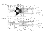
Fig. 2A is an overall view showing the pusher guidewire according to the embodiment in the state where the stent is in the midst of deployment from the front end of the catheter.Fig. 2B is a cross-sectional view ofFig. 2A . -
Fig. 3A is an overall view showing the pusher guidewire according to the embodiment in the state where the rear end of a coil has caught a gap of the stentFig. 3B is a cross-sectional view ofFig. 3A . -
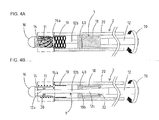
Fig. 4A is an overall view of the pusher guidewire according to the embodiment in the state where the stent deployed from the front end of the catheter has been wrapped around the outer circumference of the coil as a result of rotating a core shaft.Fig. 4B is a cross-sectional view ofFig. 4A . -
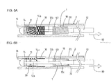
Fig. 5A is an overall view showing the pusher guidewire according to the embodiment in the state where the stent has been retrieved into the catheter while being wrapped around the outer circumference of the coil.Fig. 5B is a cross-sectional view ofFig. 5A . -
Fig. 6 is a cross-sectional view showing a pusher guidewire according to a second embodiment, which is a modification example ofFig. 2B . -
Fig. 7 is a cross-sectional view showing a pusher guidewire according to a third embodiment, which is a modification example ofFig. 2B . -
Fig. 8 is a cross-sectional view showing a pusher guidewire according to a fourth embodiment, which is a modification example ofFig. 2B . -
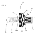
Fig. 9 is an overall view showing a pusher guidewire according to a fifth embodiment, which is a modification example ofFig. 2A . - A
pusher guidewire 1 according to the present embodiment will now be described with reference toFigs. 1A to 5B . It should be noted that, inFigs. 1A to 5B , the left side corresponds to the front end side (distal side) inserted into a body, and the right side corresponds to the rear end side (proximal side, base end side) operated by an operator such as a doctor.Figs. 1B ,2B ,3B ,4B and5B are cross-sectional views ofFigs. 1A ,2A ,3A ,4A and5A , respectively. - First, as shown in
Figs. 1A and 1B , thepusher guidewire 1 for delivering astent 10 to a target site includes acore shaft 12, afront end coil 14, afront end tip 16, and arear end coil 18. Thefront end coil 14 is wound around the outer circumference of a firstfront end portion 12a of thecore shaft 12. Thefront end tip 16 joins the front end of thecore shaft 12 and the front end of thefront end coil 14. Therear end coil 18 is arranged on the rear end side (the light side ofFigs. 1A and 1B ) of thefront end coil 14 and wound around the outer circumference of a thirdfront end portion 12c of thecore shaft 12. For the sake of convenience, thecore shaft 12 will be described as including the following three portions: the firstfront end portion 12a covered by thefront end coil 14; the thirdfront end portion 12c covered by therear end coil 18; and a secondfront end portion 12b, which is positioned between the firstfront end portion 12a and the thirdfront end portion 12c and around which thestent 10 is arranged. - A
catheter 2 has atubular body 20 into which thepusher guidewire 1 can be inserted. Thepusher guidewire 1, around which thestent 10 is arranged between thefront end coil 14 and therear end coil 18, can be inserted from a rear end opening 22 of thecatheter 2. A description of thecatheter 2 is omitted as a conventional catheter can be used as thecatheter 2. - As shown in
Fig. 1B , thefront end coil 14 is joined to the firstfront end portion 12a of thecore shaft 12 by a joining member 30 (for example, brazing filler material). Similarly, arear end 18a of therear end coil 18 is joined to the thirdfront end portion 12c of thecore shaft 12 by a joining member 32 (for example, brazing filler material). - A
pusher 40, which is joined to the secondfront end portion 12b of thecore shaft 12, is provided between thestent 10 and therear end coil 18. Thepusher 40 is constituted by a tubular body made of metal such as stainless steel, and is used to deploy thestent 10 from a front end opening 24 of thecatheter 2 when the doctor pushes thecore shaft 12 toward the front end - (the left side of
Figs. 1A and 1B ). Afront end 18b of therear end coil 18 is joined to thepusher 40. - As shown in
Figs. 1A and 1B , arear end 14a of thefront end coil 14 is a free end that is not fixed to the firstfront end portion 12a of thecore shaft 12. Furthermore, there is aclearance 15 between therear end 14a of thefront end coil 14 and the front end of thestent 10. Therefore, as will be described later, the presence of theclearance 15 prevents therear end 14a of thefront end coil 14 from catching agap 10a of thestent 10 when thepusher guidewire 1 is pushed toward the front end (the left side ofFigs. 1A and 1B ). On the other hand, when thepusher guidewire 1 is pulled toward the rear end (the right side ofFigs. 1A and 1B ), therear end 14a of thefront end coil 14 can catch thegap 10a of thestent 10. - Once the
catheter 2 has been advanced to the target site, the doctor pushes thecore shaft 12 toward the front end (the direction of arrow 50) so as to deploy thestent 10 housed in thecatheter 2 at the target site (seeFigs. 2A and 2B ). In this way, afront end portion 11 of thestent 10 is deployed from the front end opening 24 of thecatheter 2 at the target site. Thegaps 10a of thestent 10 are not expandable and hence narrow (G2) when thestent 10 is housed in thecatheter 2, but are widened (G1) once thestent 1 has been deployed from the front end opening 24 of thecatheter 2. That is to say, thegaps 10a of thestent 10 change from the narrow state G2 to the widened state G1 (seeFig. 2A ). - The
catheter 2 is fixed such that it does not move when thestent 10 is deployed at the target site. However, in the case where the target site is in a curved peripheral blood vessel and hence a front end portion of thecatheter 2 is curved, if thecore shaft 12 is forcefully pushed toward the front end (the left side ofFigs. 2A and 2B ), the front end opening 24 of thecatheter 2 may move in the same direction (toward the left side ofFigs. 2A and 2B ), possibly shifting the deployment position of thestent 10 away from the target site. The shift of the deployment position of thestent 10 away from the target site may be noticed in the midst of deployment of thestent 10 from the front end opening 24 of thecatheter 2. - In the
pusher guidewire 1 according to the present embodiment, therear end 14a of thefront end coil 14 is a free end that is not fixed to the firstfront end portion 12a of thecore shaft 12, and therefore pulling thecore shaft 12 toward the rear end (the direction of arrow 60) allows therear end 14a of thefront end coil 14 to catch agap 10a of the stent 10 (seeFigs. 3A and 3B ). - By rotating the
core shaft 12 in the circumferential direction (the direction of arrow 70) with therear end 14a of thefront end coil 14 catching thegap 10a of thestent 10, thefront end portion 11 of thestent 10 deployed from the front end opening 24 of thecatheter 2 can be wrapped around the outer circumference of the front end coil 14 (seeFigs. 4A and 4B ). - By further pulling the
core shaft 12 toward the rear end (the direction of arrow 80) with thefront end portion 11 of thestent 10 wrapped around the outer circumference of thefront end coil 14, the partially-deployedstent 10 can be retrieved into the catheter 2 (seeFigs. 5A and 5B ). - By using the free
rear end 14a of thefront end coil 14 in the above manner, thestent 10 deployed from the front end opening 24 of thecatheter 2 can be retrieved into thecatheter 2. Therefore, when the doctor attempts to retrieve thestent 10 after noticing the shift of the deployment position of thestent 10 away from the target site, a blood vessel can be prevented from being damaged by thestent 10 deployed from the front end opening 24 of thecatheter 2. - The following describes the materials of the constituent elements of the
pusher guidewire 1 according to the present embodiment. It should be noted, however, that these constituent elements are not particularly limited to being made of the following materials. - The
core shaft 12 may be formed by stainless steel (e.g., SUS 304 and SUS 316) or superelastic alloy such as Ni-Ti alloy. - The
front end coil 14 and therear end coil 18 may be formed by radiopaque wires. Such wires are made of, for example, gold, platinum, tungsten, or alloy containing these chemical elements. With thefront end coil 14 and therear end coil 18 formed by radiopaque wires, the operator can acknowledge the positions of thefront end coil 14 and therear end coil 18 on radiographic images. - The
front end coil 14 and therear end coil 18 may each be formed by a single wire or by a strand made by stranding a plurality of wires. Preferably, thefront end coil 14 and therear end coil 18 are each formed by a strand as it has superior characteristics compared to a single wire in terms of flexibility and resilience. - The
front end tip 16 may be formed by a radiopaque material, such as gold, platinum, tungsten, or alloy containing these chemical elements, so that the position of the front end of thepusher guidewire 1 can be acknowledged on radiographic images. - The joining
members - Similarly to the
core shaft 12, thepusher 40 may be formed by stainless steel (e.g., SUS 304 and SUS 316) or superelastic alloy such as Ni-Ti alloy. - A
pusher guidewire 1a according to a second embodiment will now be described with reference toFig. 6 . It should be noted that, inFig. 6 , similarly toFigs. 1A to 5B , the left side corresponds to the front end side (distal side) inserted into a body, and the right side corresponds to the rear end side (proximal side, base end side) operated by an operator such as a doctor.Fig. 6 is an enlarged cross-sectional view of section A shown inFig. 2B . - The
pusher guidewire 1a is different from thepusher guidewire 1 shown inFigs. 1A to 5B in that the outer diameter of afront end coil 64 is larger from the joiningmember 30 to arear end 64a of the front end coil 64 (D2) than from the front end of thefront end coil 64 to the joining member 30 (D1) (D2 > D1). Reducing the outer diameter D1 of thefront end coil 64 on the front end side in this manner allows thepusher guidewire 1a to reach blood vessels at more extreme ends. Furthermore, as described earlier, thegaps 10a of thestent 10 are not expandable and hence narrow (G2) when thestent 10 is housed in thecatheter 2, but are widened (G1) once thestent 10 has been deployed from the front end opening 24 of the catheter 2 (seeFigs. 2A ). Therefore, increasing the outer diameter D2 of thefront end coil 64 on the rear end side makes it easy for therear end 64a of thefront end coil 64 to catch agap 10a of thestent 10 that is starting to expand. Consequently, the partially-deployedstent 10 can be retrieved into thecatheter 2 more reliably. - A
pusher guidewire 1b according to a third embodiment will now be described with reference toFig. 7 . It should be noted that, inFig. 7 , similarly toFigs. 1A to 5B , the left side corresponds to the front end side (distal side) inserted into a body, and the right side corresponds to the rear end side (proximal side, base end side) operated by an operator such as a doctor.Fig. 7 is an enlarged cross-sectional view of section A shown inFig. 2B . - The pusher guidewire 16 is different from the
pusher guidewire 1 shown inFigs. 1A to 5B in that the wire diameter of a wire constituting afront end coil 74 is larger from the joiningmember 30 to a rear end 74a of the front end coil 74 (D4) than from the front end of thefront end coil 74 to the joining member 30 (D3) (D3 < D4). Reducing the wire diameter D3 of the wire constituting thefront end coil 74 on the front end side reduces the outer diameter of thefront end coil 74 on the front end side, thereby allowing thepusher guidewire 1b to reach blood vessels at more extreme ends. Furthermore, increasing the wire diameter D4 of the wire constituting thefront end coil 74 on the rear end side increases the force by which thefront end coil 74 on the rear end side restrains thestent 10, thereby making it easy to wrap thestent 10 deployed from the front end opening 24 of thecatheter 2 around the outer circumference of thefront end coil 74. - The wire diameter D3 of the
front end coil 74 on the front end side may be reduced as follows: after forming thefront end coil 74 by winding a wire having the large wire diameter D4 around the outer circumference of the firstfront end portion 12a of thecore shaft 12, electropolishing is applied to thefront end coil 74 between the front end thereof and the joiningmember 30 so as to transform the wire diameter of thefront end coil 74 on the front end side from the large wire diameter D4 to the small wire diameter D3. Alternatively, after forming thefront end coil 74 on the front end side by winding a wire having the small wire diameter D3 around the outer circumference of the firstfront end portion 12a of thecore shaft 12, a separate wire having the wire diameter D4, which is larger than the wire diameter D3 of thefront end coil 74 on the front end side, may be wound so as to form thefront end coil 74 on the rear end side. - A
pusher guidewire 1c according to a fourth embodiment will now be described with reference toFig. 8 . It should be noted that, inFig. 8 , similarly toFigs. 1A to 5B , the left side corresponds to the front end side (distal side) inserted into a body, and the right side corresponds to the rear end side (proximal side, base end side) operated by an operator such as a doctor.Fig. 8 is an enlarged cross-sectional view of section A shown inFig. 2B . - The pusher guidewire 1c is different from the
pusher guidewire 1 shown inFigs. 1A to 5B in that the winding pitch of afront end coil 84 is larger from the joiningmember 30 to arear end 84a of the front end coil 84 (X2) than from the front end of thefront end coil 84 to the joining member 30 (X1). By narrowing the winding pitch X1 of thefront end coil 84 on the front end side, rotation of thecore shaft 12 can be transmitted to the front end of thefront end coil 84 via the joiningmember 30. On the other hand, by widening the winding pitch X2 of thefront end coil 84 on the rear end side, the flexibility of the freerear end 84a of thefront end coil 84 can be increased, and a clearance X2 can be provided between portions of the wire constituting thefront end coil 84. As a result, the flexibility is improved, and therear end 84a of thefront end coil 84, in which the clearance X2 is provided between portions of the wire, easily catches agap 10a of thestent 10. In this way, the partially-deployedstent 10 can be retrieved into thecatheter 2 more reliably. - Finally, a
pusher guidewire 1d according to a fifth embodiment will be described with reference toFig. 9 . It should be noted that, inFig. 9 , similarly toFigs. 1A to 5B , the left side corresponds to the front end side (distal side) inserted into a body, and the right side corresponds to the rear end side (proximal side, base end side) operated by an operator such as a doctor.Fig. 9 is an enlarged cross-sectional view of section B shown inFig. 2A . - The
pusher guidewire 1d is different from thepusher guidewire 1 shown inFigs. 1A to 5B in that arear end 94a of afront end coil 94 functions as a latchingmember 90. The latchingmember 90 has a shape of a hook (seeFig. 9 ). This can reduce the risk that therear end 94a of thefront end coil 94 that caught agap 10a of thestent 10 slips off thegap 10a of thestent 10 when thecore shaft 12 is rotated in the circumferential direction (the direction of arrow 70) with therear end 94a of thefront end coil 94 catching thegap 10a of the stent 10 (seeFigs. 4A and 4B ). The shape of the latchingmember 90 is not limited to any specific shape. For example, the latchingmember 90 may have a bulged shape. - When positioning the front end opening 24 of the
catheter 2 at the target site, thecatheter 2 and thepusher guidewire pusher guidewire catheter 2 in advance (the state ofFigs. 1A and 1B ), or thepusher guidewire catheter 2 after positioning only thecatheter 2 at the target site in advance. - As described above, in the
pusher guidewire rear end front end coil front end portion 12a of thecore shaft 12. Therefore, by pulling thecore shaft 12 toward the rear end, the freerear end front end coil gap 10a of the partially-deployedstent 10. By rotating thecore shaft 12 in this state, thefront end portion 11 of thestent 10 deployed from the front end opening 24 of thecatheter 2 can be wrapped around the outer circumference of thefront end coil core shaft 12 toward the rear end with thestent 10 thus wrapped, the partially-deployedstent 10 can be retrieved into thecatheter 2. As a result, the inner wall of a normal blood vessel can be prevented from being damaged by thestent 10. -
- 1, 1a, 1b, 1c, 1d
- pusher guidewire
- 2
- catheter
- 10
- stent
- 12
- core shaft
- 14, 64, 74, 84, 94
- front end coil
- 14a, 64a, 74a, 84a, 94a
- rear end (free end) of front end coil
- 16
- front end tip
- 18
- rear end coil
- 20
- tubular body
- 22
- rear end opening
- 24
- front end opening
- 30, 32
- joining member
- 40
- pusher
- 50
- arrow (toward front end)
- 60
- arrow (toward rear end)
- 70
- arrow (rotation direction)
- 80
- arrow (toward rear end)
- 90
- latching member
Claims (5)
- A pusher guidewire (1, 1a, 1b, 1c, 1d) for delivering a stent (10) to a target site, comprising:a core shaft (12);a coil (14, 64, 74, 84, 94) covering a front end portion of the core shaft; anda joining member (30) joining the front end portion of the core shaft and the coil,characterized in that a rear end (14a, 64a, 74a, 84a, 94a) of the coil is a free end that is not fixed to the core shaft.
- The pusher guidewire according to claim 1,
characterized in that an outer diameter of the coil is larger from the joining member to the rear end of the coil (D2) than from a front end of the coil to the joining member (D1). - The pusher guidewire according to claim 1 or 2,
characterized in that a wire diameter of a wire constituting the coil is larger from the joining member to the rear end of the coil (D4) than from the front end of the coil to the joining member (D3). - The pusher guidewire according to any of claims 1 to 3,
characterized in that a winding pitch of the coil is larger from the joining member to the rear end of the coil (X2) than from the front end of the coil to the joining member (X1). - The pusher guidewire according to any of claims 1 to 4,
characterized in that the rear end of the coil is provided with a latching member (90).
Applications Claiming Priority (1)
| Application Number | Priority Date | Filing Date | Title |
|---|---|---|---|
| JP2013118988A JP2014233592A (en) | 2013-06-05 | 2013-06-05 | Pusher guide wire |
Publications (2)
| Publication Number | Publication Date |
|---|---|
| EP2810623A2 true EP2810623A2 (en) | 2014-12-10 |
| EP2810623A3 EP2810623A3 (en) | 2016-06-01 |
Family
ID=50028852
Family Applications (1)
| Application Number | Title | Priority Date | Filing Date |
|---|---|---|---|
| EP14153162.4A Withdrawn EP2810623A3 (en) | 2013-06-05 | 2014-01-30 | Pusher guidewire |
Country Status (4)
| Country | Link |
|---|---|
| US (1) | US20140364865A1 (en) |
| EP (1) | EP2810623A3 (en) |
| JP (1) | JP2014233592A (en) |
| CN (1) | CN104225761A (en) |
Families Citing this family (6)
| Publication number | Priority date | Publication date | Assignee | Title |
|---|---|---|---|---|
| US20170000980A1 (en) * | 2015-06-30 | 2017-01-05 | Boston Scientific Scimed Inc. | Robust miniature magnetic sensor |
| CN108156803B (en) * | 2015-09-18 | 2021-05-04 | 泰尔茂株式会社 | Pushable Implant Delivery System |
| CN106806044B (en) * | 2016-12-29 | 2020-03-13 | 鼎科医疗技术(苏州)有限公司 | Prosthesis recovery device |
| JP7198272B2 (en) * | 2017-08-23 | 2022-12-28 | ストライカー コーポレイション | Implant delivery system |
| US11161253B2 (en) | 2019-05-31 | 2021-11-02 | International Business Machines Corporation | Retrieving magnetically attracted objects from substantially inaccessible cavities |
| CN115414166A (en) * | 2022-09-19 | 2022-12-02 | 苏州美创医疗科技有限公司 | TIPS stent release retraction structures and methods |
Citations (1)
| Publication number | Priority date | Publication date | Assignee | Title |
|---|---|---|---|---|
| JP4498709B2 (en) | 2002-09-23 | 2010-07-07 | コーディス・ニューロバスキュラー・インコーポレイテッド | Expandable stent and delivery system |
Family Cites Families (25)
| Publication number | Priority date | Publication date | Assignee | Title |
|---|---|---|---|---|
| US4425908A (en) * | 1981-10-22 | 1984-01-17 | Beth Israel Hospital | Blood clot filter |
| US4619274A (en) * | 1985-04-18 | 1986-10-28 | Advanced Cardiovascular Systems, Inc. | Torsional guide wire with attenuated diameter |
| US5345945A (en) * | 1990-08-29 | 1994-09-13 | Baxter International Inc. | Dual coil guidewire with radiopaque distal tip |
| US5147370A (en) * | 1991-06-12 | 1992-09-15 | Mcnamara Thomas O | Nitinol stent for hollow body conduits |
| US5250071A (en) * | 1992-09-22 | 1993-10-05 | Target Therapeutics, Inc. | Detachable embolic coil assembly using interlocking clasps and method of use |
| US20030069522A1 (en) * | 1995-12-07 | 2003-04-10 | Jacobsen Stephen J. | Slotted medical device |
| US5865767A (en) * | 1996-07-10 | 1999-02-02 | Cordis Corporation | Guidewire having compound taper |
| US6409683B1 (en) * | 1998-09-30 | 2002-06-25 | Cordis Corporation | Medical guidewire with improved coil attachment |
| EP1010396B1 (en) * | 1998-12-16 | 2003-05-07 | Arthesys | Catheter system for release of embolization coils by hydraulic pressure |
| US6280465B1 (en) * | 1999-12-30 | 2001-08-28 | Advanced Cardiovascular Systems, Inc. | Apparatus and method for delivering a self-expanding stent on a guide wire |
| US20040082879A1 (en) * | 2000-01-28 | 2004-04-29 | Klint Henrik S. | Endovascular medical device with plurality of wires |
| US20040193179A1 (en) * | 2003-03-26 | 2004-09-30 | Cardiomind, Inc. | Balloon catheter lumen based stent delivery systems |
| AU2004226464A1 (en) * | 2003-03-26 | 2004-10-14 | Cardiomind, Inc. | Implant delivery technologies |
| US7771463B2 (en) * | 2003-03-26 | 2010-08-10 | Ton Dai T | Twist-down implant delivery technologies |
| US8267985B2 (en) * | 2005-05-25 | 2012-09-18 | Tyco Healthcare Group Lp | System and method for delivering and deploying an occluding device within a vessel |
| US20070213813A1 (en) * | 2005-12-22 | 2007-09-13 | Symetis Sa | Stent-valves for valve replacement and associated methods and systems for surgery |
| US7744545B2 (en) * | 2006-12-28 | 2010-06-29 | Terumo Kabushiki Kaisha | Guide wire |
| US8864789B2 (en) * | 2007-04-27 | 2014-10-21 | DePuy Synthes Products, LLC | Interventional medical device system having a spiral section and radiopaque marker and method of making the same |
| US20090306760A1 (en) * | 2008-06-06 | 2009-12-10 | Bay Street Medical | Prosthesis and delivery system |
| US20110251664A1 (en) * | 2010-04-08 | 2011-10-13 | Medtronic Vascular, Inc. | Short Legged Bifurcated Stent Graft Distal Capture Element and Method |
| JP5246884B2 (en) * | 2010-08-10 | 2013-07-24 | 朝日インテック株式会社 | Guide wire |
| JP5331836B2 (en) * | 2011-02-21 | 2013-10-30 | コヴィディエン リミテッド パートナーシップ | System and method for supplying and deploying an occlusion device in a conduit |
| GB2501714B (en) * | 2012-05-02 | 2014-05-07 | Cook Medical Technologies Llc | Implant delivery system |
| CA2818268C (en) * | 2012-06-13 | 2016-07-19 | Cook Medical Technologies Llc | Systems and methods for deploying a portion of a stent using at least one coiled member |
| JP2014100300A (en) * | 2012-11-20 | 2014-06-05 | Asahi Intecc Co Ltd | Guide wire |
-
2013
- 2013-06-05 JP JP2013118988A patent/JP2014233592A/en active Pending
-
2014
- 2014-01-14 US US14/154,845 patent/US20140364865A1/en not_active Abandoned
- 2014-01-30 EP EP14153162.4A patent/EP2810623A3/en not_active Withdrawn
- 2014-02-21 CN CN201410060176.6A patent/CN104225761A/en active Pending
Patent Citations (1)
| Publication number | Priority date | Publication date | Assignee | Title |
|---|---|---|---|---|
| JP4498709B2 (en) | 2002-09-23 | 2010-07-07 | コーディス・ニューロバスキュラー・インコーポレイテッド | Expandable stent and delivery system |
Also Published As
| Publication number | Publication date |
|---|---|
| CN104225761A (en) | 2014-12-24 |
| JP2014233592A (en) | 2014-12-15 |
| US20140364865A1 (en) | 2014-12-11 |
| EP2810623A3 (en) | 2016-06-01 |
Similar Documents
| Publication | Publication Date | Title |
|---|---|---|
| EP3011938B1 (en) | Pusher guide wire | |
| EP3081197B1 (en) | Pusher guide wire and delivery system comprising the same | |
| US11931277B2 (en) | Releasable delivery system | |
| JP4780900B2 (en) | Stent delivery device and manufacturing method thereof | |
| US20140364865A1 (en) | Pusher guidewire | |
| KR102245351B1 (en) | Braided stent with expansion ring and method of delivery | |
| JP6083533B2 (en) | Stent graft with marker and reinforcement and marker ring | |
| JP5835746B2 (en) | System and method for deploying a portion of a stent using at least one coiled member | |
| EP3025686A1 (en) | Stent delivery system | |
| JP7459421B2 (en) | Digestive tract stents | |
| US10639180B2 (en) | Systems and methods for deploying a portion of a stent using an auger-style device | |
| JP7782127B2 (en) | Stent placement system | |
| US20160143755A1 (en) | Self-expandable stent | |
| EP4659715A1 (en) | Production method for string-equipped stent, string-equipped stent, and stent delivery device | |
| JP5904557B2 (en) | Pusher guide wire | |
| JP6014046B2 (en) | Loading basket for stent delivery system and manufacturing method thereof | |
| EP2674135A1 (en) | Systems and methods for deploying a portion of a stent using at least one coiled member | |
| JP2023032478A (en) | Indwelling medical device detachment system | |
| US11123207B2 (en) | Stent delivery system | |
| JP6313183B2 (en) | Guide wire |
Legal Events
| Date | Code | Title | Description |
|---|---|---|---|
| PUAI | Public reference made under article 153(3) epc to a published international application that has entered the european phase |
Free format text: ORIGINAL CODE: 0009012 |
|
| 17P | Request for examination filed |
Effective date: 20140130 |
|
| AK | Designated contracting states |
Kind code of ref document: A2 Designated state(s): AL AT BE BG CH CY CZ DE DK EE ES FI FR GB GR HR HU IE IS IT LI LT LU LV MC MK MT NL NO PL PT RO RS SE SI SK SM TR |
|
| AX | Request for extension of the european patent |
Extension state: BA ME |
|
| PUAL | Search report despatched |
Free format text: ORIGINAL CODE: 0009013 |
|
| AK | Designated contracting states |
Kind code of ref document: A3 Designated state(s): AL AT BE BG CH CY CZ DE DK EE ES FI FR GB GR HR HU IE IS IT LI LT LU LV MC MK MT NL NO PL PT RO RS SE SI SK SM TR |
|
| AX | Request for extension of the european patent |
Extension state: BA ME |
|
| RIC1 | Information provided on ipc code assigned before grant |
Ipc: A61M 25/09 20060101ALI20160426BHEP Ipc: A61F 2/966 20130101AFI20160426BHEP Ipc: A61F 2/95 20130101ALI20160426BHEP |
|
| RAP1 | Party data changed (applicant data changed or rights of an application transferred) |
Owner name: PENTAS INC. |
|
| 18D | Application deemed to be withdrawn |
Effective date: 20161202 |
|
| STAA | Information on the status of an ep patent application or granted ep patent |
Free format text: STATUS: THE APPLICATION IS DEEMED TO BE WITHDRAWN |