EP2809048A1 - Transmission method, transmission device, transmission program, and transmission system - Google Patents
Transmission method, transmission device, transmission program, and transmission system Download PDFInfo
- Publication number
- EP2809048A1 EP2809048A1 EP13741463.7A EP13741463A EP2809048A1 EP 2809048 A1 EP2809048 A1 EP 2809048A1 EP 13741463 A EP13741463 A EP 13741463A EP 2809048 A1 EP2809048 A1 EP 2809048A1
- Authority
- EP
- European Patent Office
- Prior art keywords
- transmission
- transmission device
- reception
- data
- transmit data
- Prior art date
- Legal status (The legal status is an assumption and is not a legal conclusion. Google has not performed a legal analysis and makes no representation as to the accuracy of the status listed.)
- Granted
Links
- 230000005540 biological transmission Effects 0.000 title claims abstract description 380
- 238000000034 method Methods 0.000 title claims description 25
- 230000006854 communication Effects 0.000 claims abstract description 72
- 238000004891 communication Methods 0.000 claims abstract description 72
- 230000003321 amplification Effects 0.000 claims description 25
- 238000003199 nucleic acid amplification method Methods 0.000 claims description 25
- 230000002457 bidirectional effect Effects 0.000 claims description 8
- 238000012545 processing Methods 0.000 claims description 4
- 230000006870 function Effects 0.000 description 10
- 230000002123 temporal effect Effects 0.000 description 4
- 230000002238 attenuated effect Effects 0.000 description 3
- 238000010586 diagram Methods 0.000 description 3
- 230000007175 bidirectional communication Effects 0.000 description 2
- 230000006835 compression Effects 0.000 description 2
- 238000007906 compression Methods 0.000 description 2
- 239000000470 constituent Substances 0.000 description 2
- 230000015654 memory Effects 0.000 description 2
- 238000001514 detection method Methods 0.000 description 1
- 230000000694 effects Effects 0.000 description 1
- 239000000284 extract Substances 0.000 description 1
- 238000005259 measurement Methods 0.000 description 1
- 238000012986 modification Methods 0.000 description 1
- 230000004048 modification Effects 0.000 description 1
- 238000012544 monitoring process Methods 0.000 description 1
- 239000002674 ointment Substances 0.000 description 1
- 230000003287 optical effect Effects 0.000 description 1
- 239000013307 optical fiber Substances 0.000 description 1
- 239000004065 semiconductor Substances 0.000 description 1
- 238000006467 substitution reaction Methods 0.000 description 1
Images



Classifications
-
- H—ELECTRICITY
- H04—ELECTRIC COMMUNICATION TECHNIQUE
- H04L—TRANSMISSION OF DIGITAL INFORMATION, e.g. TELEGRAPHIC COMMUNICATION
- H04L1/00—Arrangements for detecting or preventing errors in the information received
- H04L1/0001—Systems modifying transmission characteristics according to link quality, e.g. power backoff
- H04L1/0006—Systems modifying transmission characteristics according to link quality, e.g. power backoff by adapting the transmission format
- H04L1/0007—Systems modifying transmission characteristics according to link quality, e.g. power backoff by adapting the transmission format by modifying the frame length
-
- H—ELECTRICITY
- H04—ELECTRIC COMMUNICATION TECHNIQUE
- H04L—TRANSMISSION OF DIGITAL INFORMATION, e.g. TELEGRAPHIC COMMUNICATION
- H04L1/00—Arrangements for detecting or preventing errors in the information received
- H04L1/12—Arrangements for detecting or preventing errors in the information received by using return channel
- H04L1/16—Arrangements for detecting or preventing errors in the information received by using return channel in which the return channel carries supervisory signals, e.g. repetition request signals
- H04L1/1607—Details of the supervisory signal
- H04L1/1692—Physical properties of the supervisory signal, e.g. acknowledgement by energy bursts
-
- H—ELECTRICITY
- H04—ELECTRIC COMMUNICATION TECHNIQUE
- H04L—TRANSMISSION OF DIGITAL INFORMATION, e.g. TELEGRAPHIC COMMUNICATION
- H04L1/00—Arrangements for detecting or preventing errors in the information received
- H04L1/12—Arrangements for detecting or preventing errors in the information received by using return channel
- H04L1/16—Arrangements for detecting or preventing errors in the information received by using return channel in which the return channel carries supervisory signals, e.g. repetition request signals
- H04L1/18—Automatic repetition systems, e.g. Van Duuren systems
- H04L1/1829—Arrangements specially adapted for the receiver end
- H04L1/1858—Transmission or retransmission of more than one copy of acknowledgement message
-
- H—ELECTRICITY
- H04—ELECTRIC COMMUNICATION TECHNIQUE
- H04L—TRANSMISSION OF DIGITAL INFORMATION, e.g. TELEGRAPHIC COMMUNICATION
- H04L1/00—Arrangements for detecting or preventing errors in the information received
- H04L1/12—Arrangements for detecting or preventing errors in the information received by using return channel
- H04L1/16—Arrangements for detecting or preventing errors in the information received by using return channel in which the return channel carries supervisory signals, e.g. repetition request signals
- H04L1/18—Automatic repetition systems, e.g. Van Duuren systems
- H04L1/1867—Arrangements specially adapted for the transmitter end
- H04L1/189—Transmission or retransmission of more than one copy of a message
-
- H—ELECTRICITY
- H03—ELECTRONIC CIRCUITRY
- H03G—CONTROL OF AMPLIFICATION
- H03G3/00—Gain control in amplifiers or frequency changers
- H03G3/20—Automatic control
-
- H—ELECTRICITY
- H04—ELECTRIC COMMUNICATION TECHNIQUE
- H04L—TRANSMISSION OF DIGITAL INFORMATION, e.g. TELEGRAPHIC COMMUNICATION
- H04L25/00—Baseband systems
- H04L25/02—Details ; arrangements for supplying electrical power along data transmission lines
- H04L25/0264—Arrangements for coupling to transmission lines
-
- H—ELECTRICITY
- H04—ELECTRIC COMMUNICATION TECHNIQUE
- H04L—TRANSMISSION OF DIGITAL INFORMATION, e.g. TELEGRAPHIC COMMUNICATION
- H04L25/00—Baseband systems
- H04L25/02—Details ; arrangements for supplying electrical power along data transmission lines
- H04L25/03—Shaping networks in transmitter or receiver, e.g. adaptive shaping networks
- H04L25/03878—Line equalisers; line build-out devices
- H04L25/03885—Line equalisers; line build-out devices adaptive
-
- H—ELECTRICITY
- H04—ELECTRIC COMMUNICATION TECHNIQUE
- H04L—TRANSMISSION OF DIGITAL INFORMATION, e.g. TELEGRAPHIC COMMUNICATION
- H04L43/00—Arrangements for monitoring or testing data switching networks
- H04L43/08—Monitoring or testing based on specific metrics, e.g. QoS, energy consumption or environmental parameters
- H04L43/0852—Delays
- H04L43/0864—Round trip delays
-
- H—ELECTRICITY
- H04—ELECTRIC COMMUNICATION TECHNIQUE
- H04L—TRANSMISSION OF DIGITAL INFORMATION, e.g. TELEGRAPHIC COMMUNICATION
- H04L5/00—Arrangements affording multiple use of the transmission path
- H04L5/14—Two-way operation using the same type of signal, i.e. duplex
- H04L5/16—Half-duplex systems; Simplex/duplex switching; Transmission of break signals non-automatically inverting the direction of transmission
Definitions
- the present invention relates to a transmission method, a transmission device and a transmission program as well as a transmission system for extending a transmission distance which is a distance between bidirectional transmission devices.
- time compression multiplexing (TCM) system As a transmission system between transmission devices.
- TCM time compression multiplexing
- the time compression multiplexing system is directed for realizing bidirectional transmission by performing time division on a pair of cables and repeating transmission and reception, and may be also called ping-pong transmission system.
- a technique for such a transmission system is described in
- Patent Literature 1 1
- Patent Literature 1 assumes that a distance between transmission devices is within a predetermined range.
- Patent Literature 1 does not consider that a distance between transmission devices is longer beyond a predetermined range and a time required for transmission and reception is longer along with an increase in transmission distance.
- Patent Literature 1 can be effectively used only within a predetermined distance, and when the transmission devices are far away from each other and a transmission distance therebetween is longer, a redundant time cannot be removed. Further, when a transmission distance is longer, a transmission delay time increases similarly as in a typical technique, and thus data required for communication does not fall within a predetermined frame, which causes unable communication. As described above, various problems have been caused due to an increase in transmission distance.
- a transmission device for alternately performing transmission and reception to/from a communication destination transmission device comprising:
- a transmission system in which one of a first transmission device and a second transmission device is on the master side and the other of them is on the slave side for making bidirectional transmission, both the first transmission device and the second transmission device being the transmission devices according to any one of claims 1 to 5.
- a transmission method performed by a communication source transmission device for alternately performing transmission and reception to/from a communication destination transmission device comprising:
- a transmission program for causing a computer to function as a transmission device for alternately performing transmission and reception to/from a communication destination transmission device, the transmission program for causing the computer to function as the transmission device comprising: a transmission part that transmits transmit data to the communication destination transmission device; a reception part that receives return data transmitted by the communication destination transmission device after the transmit data reaches the communication destination transmission device; and a control unit that, treats a predetermined period of time as one time unit, tries one transmission of transmit data and one reception of return data within the one time unit, and in the case of determining that the one transmission of transmit data and the one reception of return data do not fall within the one time unit, controls the transmission device such that N number of transmit data are continuously transmitted and then N number of return data are continuously received within N (N is an integer of two or more) time units.
- the present embodiment includes a transmission device 1000 and a transmission device 2000.
- the transmission device 1000 and the transmission device 2000 are connected to each other and make communication with each other. Then, the communication is assumed to conform to a two-wire bidirectional transmission system. Further, one of both is on the master side and the other is on the slave side during communication. Only two transmission devices are illustrated in Fig. 1 , which is merely exemplary. According to the present embodiment, two or more transmission devices can make bidirectional communication. As a distance (which will be called "transmission distance" as needed) between the transmission device 1000 and the transmission device 2000 is longer, a transmission delay time, which is a time between when data is output from one transmission device and when the data reaches the other transmission device, is longer.
- transmission system including the transmission device 1000 and the transmission device 2000 will be called “present system.”
- transmission device 1000 and the transmission device 2000 will be called “transmit data”
- return data data to be transmitted from the transmission device 2000 on the slave side to the transmission device 1000 on the master side
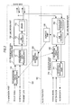
- Fig. 2 illustrates the constituents included in the transmission device 1000, and the same constituents are assumed to be included in the transmission device 2000.
- the transmission device 1000 is roughly divided into a transmission part (section or unit) 100, a frame generating part (section or unit) 200 and a reception part (section or unit) 300.
- the transmission part 100 includes a transmission frame control part 110, a transmission data control part 120 and a line driver part 130.
- the reception part 300 includes a reception data control part 310, a reception frame control part 320, a monitor part 330 and a line receiver part 340.
- the transmission frame control part 110 receives input of frame signals and system clocks defined in the present system. Further, the transmission frame control part 110 receives information on the number of frames depending on an equalizer setting value from the frame generating part 200.
- the transmission frame control part 110 generates a frame signal based on the number of frames depending on the received frame signal, system clock and equalizer setting value, and sends the frame signal to the transmission data control part 120 (step A11).
- the transmission data control part 120 receives input of the frame signal generated by the transmission frame control part 110 and input into the transmission data control part 120, the system clock and the transmit data.
- the transmission data control part 120 generates a start bit based on the frame signal generated by the transmission frame control part 110.
- the transmission data control part 120 generates a start bit and holds the transmit data in a transmission data holding part 121 inside the transmission data control part 120.
- the transmission data control part 120 serializes the generated start bit and transmit data according to a defined frame format.
- the serialized transmit data is sent to the line driver part 130 according to the system clock (step A12).
- serialization is to convert transmit data into a transmittable form.
- the line driver part 130 includes an Alternate Mark Inversion code (AMI) encoder 131 and a driver 132. Then, the line driver part 130 encodes the serialized transmit data sent from the transmission data control part 120 by the AMI encoder 131. Then, the line driver part 130 sends the encoded transmit data to the slave side by the driver 132 (step A13).
- AMI Alternate Mark Inversion code
- the slave side is the transmission device 2000 as described above, and thus the encoded transmit data is sent to the transmission device 2000.
- the AMI encoder 131 and an AMI decoder 341 described later perform encoding and decoding conforming to the AMI encoding system.
- a monitor part 330 controls an equalizer/receiver 342 inside a line receiver part 340 (step A14).
- the line receiver part 340 includes the AMI decoder 341 and the equalizer/receiver 342. Then, the line receiver part 340 receives data from the transmission device 1000 on the master side by the equalizer/receiver 342, and voltage-adjusts a level of the reception signal under control of the reception level monitor/control part 330 by an equalizer as one function of the equalizer/receiver 342.
- the line receiver part 340 decodes the reception signal by the AMI decoder 341. Then, the line receiver part 340 sends the reception signal to the reception frame control part 320 and the reception data control part 310.
- the monitor part 330 controls in step A14, and holds, as an appropriate equalizer setting value, an equalizer setting value when the reception level reaches an appropriate voltage value. Further, the monitor part 330 notifies the frame generating part 200 of the holding setting value (step A15). The specific contents of the control method in step A 14 will be described below.
- the frame generating part 200 determines the number of frames employed for one transmission and one reception depending on the equalizer setting value notified by the monitor part 330. Then, the frame generating part 200 sends the determined number of frames as information on the number of frames to the transmission frame control part 110 and the reception frame control part 320 (step A16).
- the amount of attenuation is first calculated based on a reception level.
- the amount of attenuation is a difference between a level of a transmission signal on the transmission side and a level of a reception signal on the reception side.
- one transmission device 1000, 2000 previously knows a transmission level of the other transmission device 2000, 1000, respectively. Therefore, a reception level is measured thereby to calculate the amount of attenuation.
- a transmission distance is calculated based on the amount of attenuation of the reception signal level.
- a transmission delay time is calculated based on the calculated transmission distance. How much the reception signal level attenuates by how far the distance is, and how much the transmission delay time is caused by how far the distance is are previously measured or calculated, and the above calculation can be made by use of the measurement or calculation result.
- the frame generating part 200 determines the number of frames depending on the transmission delay time.
- a communication system called ping-pong transmission system is assumed to be used.
- transmission from the master and return from the slave are performed within a predetermined time (frame time). That is, transmission of transmit data from the master and reception of the transmit data on the slave, as well as transmission of return data from the slave and reception of the return data on the master are performed within one frame time.
- the transmission delay time is accordingly longer.
- transmission from the master and return from the salve are not performed within one frame time, and thus communication cannot be made.
- the number of frames is determined at 2, for example, and transmission from the master is continuously performed twice and return from the slave is continuously performed twice within the two frames. Thereby, communication is enabled.
- the number of frames is determined as further increasing to 3 frames, 4 frames, ⁇ . That is, when the transmission from the master and the return from the slave do not fall within one frame, N (N is an integer of 2 or more) frames in which data required for communication fall may be employed. Then, after transmit data is continuously transmitted N times within N-frame time, return data may be continuously received N times.
- the frame generating part 200 determines whether one frame is employed, N frames are employed, or if N frames are employed, how many frames N are specifically employed. How many frames are employed is previously determined for how long the transmission delay time is.
- the reception frame control part 320 generates a frame signal based on the start bit detected according to the information on the number of frames input from the frame generating part 200, and sends the frame signal to the reception data control part 310 (step A17).
- the reception data control part 310 receives input of the frame signal and the system clock which are defined in the present system as well as the frame signal from the reception frame control part 320 and the receive data from the line receiver part 340.
- the reception data control part 310 extracts the receive data from the line receiver part 340 based on the frame signal from the reception frame control part 320, and holds the receive data in the reception data holding part 311.
- the reception data control part 310 converts and sends the holding receive data into a format defined in the present system according to the frame signal defined in the present system and the system clock defined in the present system (step S 17).
- the reception level monitor/control part 330 maximally amplifies an input level of the line receiver part 340 by the equalizer/receiver 342 (step A14-1).
- step A14-2 when a reception signal cannot be recognized (NO in step A14-2), the operation is continued from step A14-1.
- a reception signal is recognized (YES in step A14-2)
- a determination is made as to whether the voltage value of the reception signal is appropriate for a current amplification rate of the equalizer/receiver 342 (step A14-3). That is, a determination is made as to whether the voltage value of the output signal of the equalizer/receiver 342 is within a predetermined range.
- step A14-4 the equalizer setting value is attenuated by one step (step A14-4). That is, the amplification rate of the equalizer is lowered by one step. Then, a detection is made again as to whether the voltage value of the reception signal is an appropriate voltage value for a current amplification rate of the equalizer/receiver 342 (step A14-3). When the voltage value is not appropriate yet (NO in step A14-3), the equalizer setting value is further attenuated by one step (step A14-4).
- the operation is repeated until the voltage value of the reception signal reaches an appropriate voltage value for a current amplification rate of the equalizer/receiver 342, and when an appropriate voltage value is reached (YES in step A14-3), the amplification rate of the equalizer/receiver 342 at this time is held as an appropriate equalizer setting value and information on the held setting value is notified to the frame generating part 200 (subsequent to step A15 in Fig. 3 ).
- the information on the held setting value may be an amplification rate itself or may be a numerical value (such as the number of attenuated steps) indicating the amplification rate.
- the frame generating part 200 determines the number of frames employed for one transmission and one reception depending on the equalizer setting value notified from the monitor part 330 as described in step S16. Then, the frame generating part 200 sends the determined number of frames as information on the number of frames to the transmission frame control uni110 and the reception frame control part 320. Specifically, when the number of frames is set at 2 in the frame generating part 200, the information on the number of frames of 2 is sent to the transmission frame control part 110 and the reception frame control part 320.
- the transmission frame control part 110 generates a frame signal based on the information on the number of frames of 2 such that data for two frames defined in the present system is continuous, and sends the frame signal to the transmission data control part 120.
- the reception frame control part 320 detects a start bit considering that the data for two frames is continuously transmitted based on the information on the number of frames of 2, and generates a frame signal. The reception frame control part 320 then sends the generated frame signal to the reception data control part 310.
- a time elapse in typically transmitting and receiving transmit data will be first illustrated in a 2-frame structure in Fig. 5 .
- a time required for sending master transmit data within one frame defined in the present system is assumed as T1a in the first frame and T4a in the second frame.
- a time (transmission delay time) between when the transmit data starts being sent from the master and when it starts being received on the slave is assumed as S1a in the first frame and S4a in the second frame.
- a time required for receiving the transmit data in the slave is assumed as S2a in the first frame and S5a in the second frame.
- T1 a is equal to S2a
- T4a is equal to S5a.
- a time required for sending return data by the slave is assumed as S3a in the first frame and S6a in the second frame.
- a time (transmission delay time) between when the return data starts being sent from the slave and when it starts being received by the master is assumed as T2a in the first frame and T5a in the second frame.
- a time required for receiving the return data by the master is assumed as T3a in the first frame and T6a in the second frame.
- S3a is equal to T3a and S6a is equal to T6a.
- the temporal lengths of the transmission delay times S1a, S4a, T2a and T5a are all equal. This is because the transmission distance of the transmit data is the same as the transmission distance of the return data.
- the temporal lengths of the times T1a, S2a, S3a, T3a, T4a, S5a, S6a and T6a for transmitting and receiving the transmit data are all equal. This is because the amount of transmit data and the amount of return data per frame are all equal in any frame.
- the state illustrated in Fig. 6 is a state in which data require for communication do not fall within one frame, and indicates that the data overlaps on transmit data in a next frame and thus communication is not possible.
- a typical technique cannot address such a case. Therefore, with a typical technique, the amount of data to be transmitted or received at one time is reduced thereby to shorten the times T1a, S2a, S3a, T3a, T4a, S5a, S6a and T6a, or the transmission distance is shorten thereby to reduce the transmission delay times S1b, T2b, S4b and T5b.
- the data in the first frame and the second frame is continuous as illustrated in Fig. 7 , and the points where the transmission delay time occurs are reduced.
- the first transmission and the third transmission are continuously performed and thus a transmission delay time occurs only once for the transmit data. That is, the transmission delay time S1b occurs but the transmission delay time S4b is deleted. Similarly, the second transmission and the fourth transmission are continuously performed, and thus the transmission delay time T2b occurs but the transmission delay time T5b is deleted for the return data.
- the transmission distance can be extended according to the present embodiment.
- the present description defines that when data required for communication do not fall within one frame, data for two frames is made continuous thereby to extend the distance. Alternatively, even when data required for communication do not fall within two or more frames, the same principle is employed to determine the number of consecutive frames as three frames, four frames and so one, thereby extending the distance.
- data for three frames may be made continuous.
- data for four frames may be made continuous. That is, when data required for communication do not fall in one frame, the number of consecutive frames may be N (N is an integer of 2 or more) frames in which data required for communication fall. Then, after transmit data is continuously transmitted N times, return data may be continuously received N times.
- a transmission distance is determined by measuring a voltage value of a reception signal in the above description, but instead, a transmission delay time is calculated based on a difference between an expected reception time and an actual reception time, and N can be determined depending on the transmission delay time.
- a time between the start of transmitting transmit data and the end of receiving return data is measured thereby to calculate a transmission delay time. Then, when it is determined that data do not fall within one frame in a current transmission delay time, it is determined that the data cannot be transmitted and received within one frame. Then, when it is determined that data cannot be transmitted and received within one frame, data for a plurality of frames is continuously transmitted and received thereby to extend the transmission distance.
- a value which changes depending on the amount of attenuation of a reception signal is first used. This time, a setting value of the equalizer/receiver 342 is assumed to be used as the value, which is assumed as ⁇ . A transmission delay time ⁇ T is calculated based on this ⁇ . Further, the number of frames n is determined based on the transmission delay time ⁇ T.
- a relationship between ⁇ and a transmission delay time ⁇ T is previously measured or calculated to be in a table.
- a setting value ⁇ of the equalizer/receiver 342 is associated with a transmission delay time ⁇ T to be a first table.
- the number of frames to be determined is n.
- n number of transmit data are transmitted and n number of return data are received within n frames.
- TD time required for transmitting or receiving one transmit data or one return data
- n ⁇ TD time required for transmitting or receiving n number of transmit data or n number of return data within n frames
- TF length of a frame
- n when n number of transmit data are transmitted and n number of return data are received within n frames, n needs to meet the following condition a.
- Equation (1) can be derived based on the condition a.
- the frame generating part 200 calculates a transmission delay time ⁇ T with reference to the first table and further makes calculations based on the calculated transmission delay time ⁇ T and Mathematical formula (1) thereby to determine n.
- a relationship between a transmission delay time ⁇ T and n is previously calculated based on Mathematical formula (1) and the calculation result may be assumed as a table instead of calculating n based on Mathematical formula (1). That is, a second table in which a transmission delay time ⁇ T is associated with n may be created by previously making calculations based on Mathematical formula (1). By doing so, the frame generating part 200 can determine n by sequentially referring to the first table and the second table.
- a third table may be created instead of employing the first table and the second table. That is, a table in which ⁇ is associated with n is created and this table is assumed as a third table. By doing so, the frame generating part 200 can determine n with reference to the third table.
- a predetermined temporal margin may be employed for the number of frames as needed in consideration of an error in a relationship between the amount of signal attenuation and the transmission delay time or an accuracy of communication.
- the temporal margin is assumed as k and Mathematical formula (1) may be replaced with the following Mathematical formula (2).
- k is increased so that an accuracy of completing transmission and reception within n frames increases.
- k is increased, an unwanted time may occur within the frames, and thus k needs to be an appropriate value in consideration of the points.
- the above transmission device can be realized in hardware, software or a combination thereof.
- the transmission method performed by the above transmission device can be realized in hardware, software or a combination thereof.
- realization in software indicates that a computer reads a program for realization.
- the program can be stored by use of various types of non-transitory computer readable mediums and can be supplied to the computer.
- the non-transitory computer readable mediums include various types of tangible storage mediums.
- Exemplary non-transitory computer readable mediums include magnetic recording mediums (such as flexible disk, magnetic tape and hard disk drive), magnetooptical recording mediums (such as magnetooptical disk), CD-ROM (Read Only Memory), CD-R, CD-R/W, and semiconductor memories (such as mask ROM, Programmable ROM (PROM), Erasable (EPROM PROM), flash ROM and random access memory (RAM)).
- the program may be supplied to the computer via various types of transitory computer readable mediums.
- Exemplary transitory computer readable mediums include an electric signal, an optical signal and an electromagnetic wave.
- the transitory computer readable mediums can supply the program to the computer via a wired communication path such as electric wire and optical fiber, or a wireless communication path.
- a transmission device for alternately performing transmission and reception to/from a communication destination transmission device comprising: a transmission part that transmits transmit data to the communication destination transmission device; a reception part that receives return data transmitted by the communication destination transmission device after the transmit data reaches the communication destination transmission device; and a control part that, treats a predetermined period of time as one time unit, tries one transmission of transmit data and one reception of return data within the one time unit, and in the case of determining that the one transmission of transmit data and the one reception of return data do not fall within the one time unit, controls the transmission device such that N number of transmit data are continuously transmitted and then N number of return data are continuously received within N (N is an integer of two or more) time units.
- the transmission device according to any one of Supplementary notes 1 to 4, wherein the amount of transmit data for the one transmission and the amount of return data for the one reception are constant.
- a transmission system in which one of a first transmission device and a second transmission device is on the master side and the other of them is on the slave side for making bidirectional transmission, both the first transmission device and the second transmission device being the transmission devices according to any one of Supplementary notes 1 to 5.
- the communication source transmission device includes an equalizer that amplifies a voltage value of the received return data at an adjustable amplification rate, and processing of setting an amplification of the equalizer at a first setting value, confirming whether an output voltage value of the equalizer is appropriate, when the output voltage value of the equalizer is not appropriate, setting the amplification rate at a second setting value lower by one step than the first setting value, and reconfirming whether an output voltage value of the equalizer is appropriate is repeated by newly applying the second setting value as the first setting value, and whether one transmission of transmit data and one reception of return data fall within one time unit, and when one transmission of transmit data and one reception of return data do not fall within one time unit, what the number of N is are determined depending on a setting value of the amplification rate of the equalizer when the output voltage value of the equalizer reaches an appropriate value.
- a transmission program for causing a computer to function as a transmission device for alternately performing transmission and reception to/from a communication destination transmission device comprising: a transmission part that transmits transmit data to the communication destination transmission device; a reception part that receives return data transmitted by the communication destination transmission device after the transmit data reaches the communication destination transmission device; and a control part that, treats a predetermined period of time as one time unit, tries one transmission of transmit data and one reception of return data within the one time unit, and in the case of determining that the one transmission of transmit data and the one reception of return data do not fall within the one time unit, controls the transmission device such that N number of transmit data are continuously transmitted and then N number of return data are continuously received within N (N is an integer of two or more) time units.
- the transmission program according to Supplementary note 12 for causing the computer to further function as a transmission device, the transmission device which further includes a monitor part that monitors a voltage value of the received return data, and determines whether one transmission of transmit data and one reception of return data fall within one time unit, and when one transmission of transmit data and one reception of return data do not fall within one time unit, what the N value is based on a voltage value monitored by the monitor part.
- the transmission program according to Supplementary note 13 the transmission program for causing the computer to further function as a transmission device, the transmission device which further includes an equalizer that amplifies a voltage value of receive data received by the reception part at an adjustable amplification rate, and repeats processing of setting an amplification rate of the equalizer at a first setting value, confirming whether an output value of the equalizer is appropriate, when the output value of the equalizer is not appropriate, setting the amplification rate at a second setting value lower by one step than the first setting value, and reconfirming whether an output voltage value of the equalizer is appropriate by newly applying the second setting value as the first setting value, and determines whether one transmission of transmit data and one reception of return data fall within one time unit, and when one transmission of transmit data and one reception of return data do not fall within one time unit, what the number N is depending on a setting value of the amplification rate of the equalizer when an output voltage value of the equalizer reaches an appropriate value.
- the transmission program according to Supplementary note 12 for causing the computer to further function as a transmission device, the transmission device which further includes a monitor part that measuring a time between the start of one transmission of transmit data and the end of one reception of return data, and calculates a transmission delay time for transmitting and receiving transmit data and return data based on a time measured by the monitor part, and determines whether one transmission of transmit data and one reception of return data fall within one time unit, or when one transmission of transmit data and one reception of return data do not fall within one time unit, what the N value is based on the transmission delay time
- the present invention is applicable to any transmission device for performing transmission and reception within a predetermined time.
Landscapes
- Engineering & Computer Science (AREA)
- Signal Processing (AREA)
- Computer Networks & Wireless Communication (AREA)
- Power Engineering (AREA)
- Quality & Reliability (AREA)
- Communication Control (AREA)
- Cable Transmission Systems, Equalization Of Radio And Reduction Of Echo (AREA)
- Bidirectional Digital Transmission (AREA)
Abstract
Description
- The present invention relates to a transmission method, a transmission device and a transmission program as well as a transmission system for extending a transmission distance which is a distance between bidirectional transmission devices.
- There is a time compression multiplexing (TCM) system as a transmission system between transmission devices. The time compression multiplexing system is directed for realizing bidirectional transmission by performing time division on a pair of cables and repeating transmission and reception, and may be also called ping-pong transmission system. A technique for such a transmission system is described in
- With the bidirectional transmission device described in Patent Literature 1, when a transmission distance between a master machine and a slave machine is within a predetermined distance, a redundant period in a frame period is removed, thereby transmitting more data than in typical bidirectional transmission devices. Thereby, a performance of the entire transmission system can be enhanced.
- {PTL 1}
JP-A-Hei 11-215107 - However, the technique described in Patent Literature 1 described above assumes that a distance between transmission devices is within a predetermined range.
- That is, the technique described in Patent Literature 1 does not consider that a distance between transmission devices is longer beyond a predetermined range and a time required for transmission and reception is longer along with an increase in transmission distance.
- Thus, the technique described in Patent Literature 1 can be effectively used only within a predetermined distance, and when the transmission devices are far away from each other and a transmission distance therebetween is longer, a redundant time cannot be removed. Further, when a transmission distance is longer, a transmission delay time increases similarly as in a typical technique, and thus data required for communication does not fall within a predetermined frame, which causes unable communication. As described above, various problems have been caused due to an increase in transmission distance.
- In order to avoid the problems, a transmission distance has needed to be restricted or part of data required for communication has needed to be deleted.
- It is therefore a purpose of the present invention to provide a transmission method, a transmission device and a transmission program as well as a transmission system capable of making communication even when transmission devices are far away from each other and a transmission distance therebetween is longer.
- According to a first aspect of the present invention, there is provided a transmission device for alternately performing transmission and reception to/from a communication destination transmission device, the transmission device comprising:
- a transmission part that transmits transmit data to the communication destination transmission device;
- a reception part that receives return data transmitted by the communication destination transmission device after the transmit data reaches the communication destination transmission device; and
- a control part that, treats a predetermined period of time as one time unit, tries one transmission of transmit data and one reception of return data within the one time unit,
- and in the case of determining that the one transmission of transmit data and the one reception of return data do not fall within the one time unit, controls the transmission device such that N number of transmit data are continuously transmitted and then N number of return data are continuously received within N (N is an integer of two or more) time units.
- According to a second aspect of the present invention, there is provided a transmission system in which one of a first transmission device and a second transmission device is on the master side and the other of them is on the slave side for making bidirectional transmission,
both the first transmission device and the second transmission device being the transmission devices according to any one of claims 1 to 5. - According to a third aspect of the present invention, there is provided a transmission method performed by a communication source transmission device for alternately performing transmission and reception to/from a communication destination transmission device,
the transmission method comprising: - transmitting transmit data to the communication destination transmission device;
- receiving return data transmitted by the communication destination transmission device after the transmit data reaches the communication destination transmission device; and
- treating a predetermined period of time as one time unit, trying one transmission of transmit data and one reception of return data within the one time unit, and in the case of determining that the one transmission of transmit data and the one reception of return data do not fall within the one time unit, controlling the communication source transmission device such that N number of transmit data are continuously transmitted and then N number of return data are continuously received within N (N is an integer of two or more) time units.
- According to a fourth aspect of the present invention, there is provided a transmission program for causing a computer to function as a transmission device for alternately performing transmission and reception to/from a communication destination transmission device,
the transmission program for causing the computer to function as the transmission device comprising:
a transmission part that transmits transmit data to the communication destination transmission device;
a reception part that receives return data transmitted by the communication destination transmission device after the transmit data reaches the communication destination transmission device; and
a control unit that, treats a predetermined period of time as one time unit, tries one transmission of transmit data and one reception of return data within the one time unit, and in the case of determining that the one transmission of transmit data and the one reception of return data do not fall within the one time unit, controls the transmission device such that N number of transmit data are continuously transmitted and then N number of return data are continuously received within N (N is an integer of two or more) time units. - According to the present invention, it is possible to make communication even when transmission devices are far away from each other and a transmission distance therebetween is longer.
-
- {
Fig. 1 } A figure illustrates a basic structure of an entire transmission system according to an embodiment of the present invention. - {
Fig. 2 } A figure illustrates a basic structure of a transmission device according to the embodiment of the present invention. - {
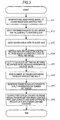
Fig. 3 } A figure illustrates a flowchart of basic operations of the transmission device according to the embodiment of the present invention. - {
Fig. 4 } A figure illustrates a flowchart of basic operations of a monitor part according to the embodiment of the present invention. - {
Fig. 5 } A figure illustrates a diagram (1/3) for explaining an advantage of the embodiment of the present invention. - {
Fig. 6 } A figure illustrates a diagram (2/3) for explaining an advantage of the embodiment of the present invention. - {
Fig. 7 } A figure illustrates a diagram (3/3) for explaining an advantage of the embodiment of the present invention. -
- 100: Transmission part
- 110: Transmission frame control part
- 120: Transmission data control part
- 121: Transmission data holding part
- 130: Line driver part
- 131: AMI encoder
- 132: Driver
- 200: Frame generating part
- 300: Reception part
- 310: Reception data control part
- 311: Reception data holding part
- 320: Reception frame control part
- 330: Monitor part
- 340: Line receiver part
- 341: AMI decoder
- 342: Equalizer/receiver
- 1000, 2000: Transmission device
- An embodiment according to the present invention will be described below in detail with reference to the drawings.
- With reference to
Fig. 1 , the present embodiment includes atransmission device 1000 and atransmission device 2000. Thetransmission device 1000 and thetransmission device 2000 are connected to each other and make communication with each other. Then, the communication is assumed to conform to a two-wire bidirectional transmission system. Further, one of both is on the master side and the other is on the slave side during communication. Only two transmission devices are illustrated inFig. 1 , which is merely exemplary. According to the present embodiment, two or more transmission devices can make bidirectional communication. As a distance (which will be called "transmission distance" as needed) between thetransmission device 1000 and thetransmission device 2000 is longer, a transmission delay time, which is a time between when data is output from one transmission device and when the data reaches the other transmission device, is longer. - Furthermore, it is assumed herein that bidirectional communication is made between the
transmission device 1000 on the master side and thetransmission device 2000 on the slave side. In the following description, the transmission system including thetransmission device 1000 and thetransmission device 2000 will be called "present system." Moreover, data to be transmitted from thetransmission device 1000 on the master side to thetransmission device 2000 on the slave side will be called "transmit data" and data to be transmitted from thetransmission device 2000 on the slave side to thetransmission device 1000 on the master side will be called "return data." - A detailed structure of the transmission device will be described below with reference to
Fig. 2. Fig. 2 illustrates the constituents included in thetransmission device 1000, and the same constituents are assumed to be included in thetransmission device 2000. - The
transmission device 1000 is roughly divided into a transmission part (section or unit) 100, a frame generating part (section or unit) 200 and a reception part (section or unit) 300. Thetransmission part 100 includes a transmissionframe control part 110, a transmissiondata control part 120 and aline driver part 130. Thereception part 300 includes a receptiondata control part 310, a receptionframe control part 320, amonitor part 330 and aline receiver part 340. - The functions of the respective parts will be described below in detail and the basic operations of the present embodiment will be described with reference to the flowchart of
Fig. 3 . - The transmission
frame control part 110 receives input of frame signals and system clocks defined in the present system. Further, the transmissionframe control part 110 receives information on the number of frames depending on an equalizer setting value from theframe generating part 200. - Then, the transmission
frame control part 110 generates a frame signal based on the number of frames depending on the received frame signal, system clock and equalizer setting value, and sends the frame signal to the transmission data control part 120 (step A11). - The transmission data control
part 120 receives input of the frame signal generated by the transmissionframe control part 110 and input into the transmission data controlpart 120, the system clock and the transmit data. - The transmission data control
part 120 generates a start bit based on the frame signal generated by the transmissionframe control part 110. The transmission data controlpart 120 generates a start bit and holds the transmit data in a transmissiondata holding part 121 inside the transmission data controlpart 120. - Subsequently, the transmission data control
part 120 serializes the generated start bit and transmit data according to a defined frame format. The serialized transmit data is sent to theline driver part 130 according to the system clock (step A12). Herein, serialization is to convert transmit data into a transmittable form. - The
line driver part 130 includes an Alternate Mark Inversion code (AMI)encoder 131 and adriver 132. Then, theline driver part 130 encodes the serialized transmit data sent from the transmission data controlpart 120 by theAMI encoder 131. Then, theline driver part 130 sends the encoded transmit data to the slave side by the driver 132 (step A13). - Herein, the slave side is the
transmission device 2000 as described above, and thus the encoded transmit data is sent to thetransmission device 2000. - According to the present embodiment, the
AMI encoder 131 and anAMI decoder 341 described later perform encoding and decoding conforming to the AMI encoding system. This is merely exemplary, and any encoding system other than the AMI encoding system may be accorded. - A
monitor part 330 controls an equalizer/receiver 342 inside a line receiver part 340 (step A14). Herein, theline receiver part 340 includes theAMI decoder 341 and the equalizer/receiver 342. Then, theline receiver part 340 receives data from thetransmission device 1000 on the master side by the equalizer/receiver 342, and voltage-adjusts a level of the reception signal under control of the reception level monitor/control part 330 by an equalizer as one function of the equalizer/receiver 342. Theline receiver part 340 decodes the reception signal by theAMI decoder 341. Then, theline receiver part 340 sends the reception signal to the receptionframe control part 320 and the reception data controlpart 310. - The
monitor part 330 controls in step A14, and holds, as an appropriate equalizer setting value, an equalizer setting value when the reception level reaches an appropriate voltage value. Further, themonitor part 330 notifies theframe generating part 200 of the holding setting value (step A15). The specific contents of the control method in step A 14 will be described below. - The
frame generating part 200 determines the number of frames employed for one transmission and one reception depending on the equalizer setting value notified by themonitor part 330. Then, theframe generating part 200 sends the determined number of frames as information on the number of frames to the transmissionframe control part 110 and the reception frame control part 320 (step A16). - Determining the number of frames will be described herein. According to the present embodiment, the amount of attenuation is first calculated based on a reception level. Herein, the amount of attenuation is a difference between a level of a transmission signal on the transmission side and a level of a reception signal on the reception side. Then, one
transmission device other transmission device - The
frame generating part 200 determines the number of frames depending on the transmission delay time. - According to the present embodiment, a communication system called ping-pong transmission system is assumed to be used. In the ping-pong transmission system, transmission from the master and return from the slave are performed within a predetermined time (frame time). That is, transmission of transmit data from the master and reception of the transmit data on the slave, as well as transmission of return data from the slave and reception of the return data on the master are performed within one frame time.
- However, when the transmission distance is longer, the transmission delay time is accordingly longer. Thus, in a certain transmission distance or more, transmission from the master and return from the salve are not performed within one frame time, and thus communication cannot be made.
- Therefore, according to the present embodiment, when it is determined that transmission from the master and return from the slave do not fall within one frame time, the number of frames is determined at 2, for example, and transmission from the master is continuously performed twice and return from the slave is continuously performed twice within the two frames. Thereby, communication is enabled. When it is determined that the transmission from the master and the return from the slave do not fall within two frames, the number of frames is determined as further increasing to 3 frames, 4 frames, ···. That is, when the transmission from the master and the return from the slave do not fall within one frame, N (N is an integer of 2 or more) frames in which data required for communication fall may be employed. Then, after transmit data is continuously transmitted N times within N-frame time, return data may be continuously received N times.
- In this way, the
frame generating part 200 determines whether one frame is employed, N frames are employed, or if N frames are employed, how many frames N are specifically employed. How many frames are employed is previously determined for how long the transmission delay time is. - The reception
frame control part 320 generates a frame signal based on the start bit detected according to the information on the number of frames input from theframe generating part 200, and sends the frame signal to the reception data control part 310 (step A17). - The reception data control
part 310 receives input of the frame signal and the system clock which are defined in the present system as well as the frame signal from the receptionframe control part 320 and the receive data from theline receiver part 340. - Then, the reception data control
part 310 extracts the receive data from theline receiver part 340 based on the frame signal from the receptionframe control part 320, and holds the receive data in the receptiondata holding part 311. - Then, the reception data control
part 310 converts and sends the holding receive data into a format defined in the present system according to the frame signal defined in the present system and the system clock defined in the present system (step S 17). - The above described has been made by way of the operations of the respective parts in the
transmission device 1000 on the master side, but the respective parts of thetransmission device 2000 on the slave side operate in the same way. - The operations of the
line receiver part 340 according to the control operations of themonitor part 330 and its control will be described below according to the present embodiment with reference to the flowchart ofFig. 4 . The operations correspond to step A14 inFig. 3 . - The reception level monitor/
control part 330 maximally amplifies an input level of theline receiver part 340 by the equalizer/receiver 342 (step A14-1). - As a result of maximum amplification, when a reception signal cannot be recognized (NO in step A14-2), the operation is continued from step A14-1. On the other hand, when a reception signal is recognized (YES in step A14-2), a determination is made as to whether the voltage value of the reception signal is appropriate for a current amplification rate of the equalizer/receiver 342 (step A14-3). That is, a determination is made as to whether the voltage value of the output signal of the equalizer/
receiver 342 is within a predetermined range. - When the voltage value of the reception signal is not an appropriate voltage value for a current amplification rate of the equalizer/receiver 342 (NO in step A14-3), the equalizer setting value is attenuated by one step (step A14-4). That is, the amplification rate of the equalizer is lowered by one step. Then, a detection is made again as to whether the voltage value of the reception signal is an appropriate voltage value for a current amplification rate of the equalizer/receiver 342 (step A14-3). When the voltage value is not appropriate yet (NO in step A14-3), the equalizer setting value is further attenuated by one step (step A14-4). The operation is repeated until the voltage value of the reception signal reaches an appropriate voltage value for a current amplification rate of the equalizer/
receiver 342, and when an appropriate voltage value is reached (YES in step A14-3), the amplification rate of the equalizer/receiver 342 at this time is held as an appropriate equalizer setting value and information on the held setting value is notified to the frame generating part 200 (subsequent to step A15 inFig. 3 ). The information on the held setting value may be an amplification rate itself or may be a numerical value (such as the number of attenuated steps) indicating the amplification rate. - Thereafter, the
frame generating part 200 determines the number of frames employed for one transmission and one reception depending on the equalizer setting value notified from themonitor part 330 as described in step S16. Then, theframe generating part 200 sends the determined number of frames as information on the number of frames to the transmission frame control uni110 and the receptionframe control part 320. Specifically, when the number of frames is set at 2 in theframe generating part 200, the information on the number of frames of 2 is sent to the transmissionframe control part 110 and the receptionframe control part 320. - The transmission
frame control part 110 generates a frame signal based on the information on the number of frames of 2 such that data for two frames defined in the present system is continuous, and sends the frame signal to the transmission data controlpart 120. - The reception
frame control part 320 detects a start bit considering that the data for two frames is continuously transmitted based on the information on the number of frames of 2, and generates a frame signal. The receptionframe control part 320 then sends the generated frame signal to the reception data controlpart 310. - The advantages of the present embodiment will be described below with reference to
Fig. 5 to Fig. 7 . - A time elapse in typically transmitting and receiving transmit data will be first illustrated in a 2-frame structure in
Fig. 5 . - A time required for sending master transmit data within one frame defined in the present system is assumed as T1a in the first frame and T4a in the second frame. A time (transmission delay time) between when the transmit data starts being sent from the master and when it starts being received on the slave is assumed as S1a in the first frame and S4a in the second frame. A time required for receiving the transmit data in the slave is assumed as S2a in the first frame and S5a in the second frame. Herein, T1 a is equal to S2a and T4a is equal to S5a. Similarly, for inversely transmitted and received data, a time required for sending return data by the slave is assumed as S3a in the first frame and S6a in the second frame. A time (transmission delay time) between when the return data starts being sent from the slave and when it starts being received by the master is assumed as T2a in the first frame and T5a in the second frame. A time required for receiving the return data by the master is assumed as T3a in the first frame and T6a in the second frame. Herein, S3a is equal to T3a and S6a is equal to T6a.
- At this time, the temporal lengths of the transmission delay times S1a, S4a, T2a and T5a are all equal. This is because the transmission distance of the transmit data is the same as the transmission distance of the return data.
- With partially repeated description, the temporal lengths of the times T1a, S2a, S3a, T3a, T4a, S5a, S6a and T6a for transmitting and receiving the transmit data are all equal. This is because the amount of transmit data and the amount of return data per frame are all equal in any frame.
- A case in which the transmission distance is longer than in
Fig. 5 will be assumed below. When the transmission distance is extended, the transmission delay time increases, and thus a time elapse for transmitting and receiving data is extended from the transmission delay times S1a, T2a, S4a and T5a inFig. 5 to the transmission delay times S1b, T2b, S4b and T5b as inFig. 6 , respectively. - The state illustrated in
Fig. 6 is a state in which data require for communication do not fall within one frame, and indicates that the data overlaps on transmit data in a next frame and thus communication is not possible. A typical technique cannot address such a case. Therefore, with a typical technique, the amount of data to be transmitted or received at one time is reduced thereby to shorten the times T1a, S2a, S3a, T3a, T4a, S5a, S6a and T6a, or the transmission distance is shorten thereby to reduce the transmission delay times S1b, T2b, S4b and T5b. - On the other hand, according to the present embodiment, the data in the first frame and the second frame is continuous as illustrated in
Fig. 7 , and the points where the transmission delay time occurs are reduced. - With reference to
Fig. 7 , the first transmission and the third transmission are continuously performed and thus a transmission delay time occurs only once for the transmit data. That is, the transmission delay time S1b occurs but the transmission delay time S4b is deleted. Similarly, the second transmission and the fourth transmission are continuously performed, and thus the transmission delay time T2b occurs but the transmission delay time T5b is deleted for the return data. - Consequently, even if the transmission delay time length and the amount of data to be transmitted or returned are the same, data require for communication is accepted. Thereby, the transmission distance can be extended according to the present embodiment.
- The present description defines that when data required for communication do not fall within one frame, data for two frames is made continuous thereby to extend the distance. Alternatively, even when data required for communication do not fall within two or more frames, the same principle is employed to determine the number of consecutive frames as three frames, four frames and so one, thereby extending the distance.
- For example, when data required for communication do not fall within two frames, data for three frames may be made continuous. When data required for communication do not fall within three frames, data for four frames may be made continuous. That is, when data required for communication do not fall in one frame, the number of consecutive frames may be N (N is an integer of 2 or more) frames in which data required for communication fall. Then, after transmit data is continuously transmitted N times, return data may be continuously received N times.
- A variant of the above embodiment will be described. A transmission distance is determined by measuring a voltage value of a reception signal in the above description, but instead, a transmission delay time is calculated based on a difference between an expected reception time and an actual reception time, and N can be determined depending on the transmission delay time.
- Specifically, when data cannot be transmitted and received within one frame is previously measured by how long a transmission delay time is.
- Then, a time between the start of transmitting transmit data and the end of receiving return data is measured thereby to calculate a transmission delay time. Then, when it is determined that data do not fall within one frame in a current transmission delay time, it is determined that the data cannot be transmitted and received within one frame. Then, when it is determined that data cannot be transmitted and received within one frame, data for a plurality of frames is continuously transmitted and received thereby to extend the transmission distance.
- A specific example of the method for determining the number of frames in the
frame generating part 200 will be described herein. - According to the present embodiment, a value which changes depending on the amount of attenuation of a reception signal is first used. This time, a setting value of the equalizer/
receiver 342 is assumed to be used as the value, which is assumed as α. A transmission delay time ΔT is calculated based on this α. Further, the number of frames n is determined based on the transmission delay time ΔT. - Herein, a relationship between α and a transmission delay time ΔT is previously measured or calculated to be in a table. In the present description, a setting value α of the equalizer/
receiver 342 is associated with a transmission delay time ΔT to be a first table. - A method for determining the number of frames n based on a transmission delay time ΔT will be described below.
- This time, the number of frames to be determined is n. Then, n number of transmit data are transmitted and n number of return data are received within n frames. Thereby, when a time required for transmitting or receiving one transmit data or one return data is assumed as TD, a time required for transmitting or receiving n number of transmit data or n number of return data within n frames is assumed as n·TD, respectively. Further, a length of a frame is assumed as TF. Additionally, when n number of transmit data are transmitted and n number of return data are received within n frames, a transmission delay time ΔT is caused on transmission and on reception, respectively. Thereby, 2·ΔT is cased within n frames.
- From the above, when n number of transmit data are transmitted and n number of return data are received within n frames, n needs to meet the following condition a.
- [Math. 1]

- Then, Equation (1) can be derived based on the condition a.
- [Math. 2]

- The
frame generating part 200 calculates a transmission delay time ΔT with reference to the first table and further makes calculations based on the calculated transmission delay time ΔT and Mathematical formula (1) thereby to determine n. - A relationship between a transmission delay time ΔT and n is previously calculated based on Mathematical formula (1) and the calculation result may be assumed as a table instead of calculating n based on Mathematical formula (1). That is, a second table in which a transmission delay time ΔT is associated with n may be created by previously making calculations based on Mathematical formula (1). By doing so, the
frame generating part 200 can determine n by sequentially referring to the first table and the second table. - A third table may be created instead of employing the first table and the second table. That is, a table in which α is associated with n is created and this table is assumed as a third table. By doing so, the
frame generating part 200 can determine n with reference to the third table. - A predetermined temporal margin may be employed for the number of frames as needed in consideration of an error in a relationship between the amount of signal attenuation and the transmission delay time or an accuracy of communication. The temporal margin is assumed as k and Mathematical formula (1) may be replaced with the following Mathematical formula (2).
- [Math. 3]

- k is increased so that an accuracy of completing transmission and reception within n frames increases. On the other hand, when k is increased, an unwanted time may occur within the frames, and thus k needs to be an appropriate value in consideration of the points.
- The above transmission device can be realized in hardware, software or a combination thereof. The transmission method performed by the above transmission device can be realized in hardware, software or a combination thereof. Herein, realization in software indicates that a computer reads a program for realization.
- The program can be stored by use of various types of non-transitory computer readable mediums and can be supplied to the computer. The non-transitory computer readable mediums include various types of tangible storage mediums. Exemplary non-transitory computer readable mediums include magnetic recording mediums (such as flexible disk, magnetic tape and hard disk drive), magnetooptical recording mediums (such as magnetooptical disk), CD-ROM (Read Only Memory), CD-R, CD-R/W, and semiconductor memories (such as mask ROM, Programmable ROM (PROM), Erasable (EPROM PROM), flash ROM and random access memory (RAM)). The program may be supplied to the computer via various types of transitory computer readable mediums. Exemplary transitory computer readable mediums include an electric signal, an optical signal and an electromagnetic wave. The transitory computer readable mediums can supply the program to the computer via a wired communication path such as electric wire and optical fiber, or a wireless communication path.
- The above embodiment is suitable for the present invention, and the scope of the present invention is not limited to only the above embodiment and various modifications may be made to the embodiment without departing from the spirit of the present invention.
- The present application is based on Japanese Patent application No.
2012-012164 (filed on January 24, 2012 2012-012164 2012-012164 2012-012164 - The representative embodiment according to the present invention has been described in detail, and various changes, substitutions and alternatives should be understood without departing from the spirit and scope of the present invention defined in Claims. Further, even if the claims are corrected in the application procedure, the inventors intend to maintain the equivalent scope of the claimed invention.
- Part or all of the above embodiment can be described as in the following Supplementary notes, but is not limited to the following.
- A transmission device for alternately performing transmission and reception to/from a communication destination transmission device, the transmission device comprising:
a transmission part that transmits transmit data to the communication destination transmission device;
a reception part that receives return data transmitted by the communication destination transmission device after the transmit data reaches the communication destination transmission device; and
a control part that, treats a predetermined period of time as one time unit, tries one transmission of transmit data and one reception of return data within the one time unit, and in the case of determining that the one transmission of transmit data and the one reception of return data do not fall within the one time unit, controls the transmission device such that N number of transmit data are continuously transmitted and then N number of return data are continuously received within N (N is an integer of two or more) time units. - The transmission device according to Supplementary note 1, further comprising:
- a monitor part that monitors a voltage value of the received return data,
- wherein whether the one transmission of transmit data and the one reception of return data falls within the one time unit, and when the one transmission of transmit data and the one reception of return data do not fall within the one time unit, what the value of
- N is are determined based on the voltage value monitored by the monitor part.
- The transmission device according to Supplementary note 2, further comprising:
- an equalizer that amplifies a voltage value of receive data received by the reception part at an adjustable amplification rate,
- wherein processing of setting an amplification rate of the equalizer at a first setting value, confirming whether an output voltage value of the equalizer is appropriate, and when the output voltage value of the equalizer is not appropriate, setting the amplification rate at a second setting value lower by one step than the first setting value, and reconfirming whether an output voltage value of the equalizer is appropriate is repeated by newly applying the second setting value as the first setting value, and whether the one transmission of transmit data and the one reception of return data falls within the one time unit, and when the one transmission of transmit data and the one reception of return data do not fall within the one time unit, what the number of N is are determined depending on a setting value of the amplification rate of the equalizer when the output voltage value of the equalizer reaches an appropriate value.
- The transmission device according to Supplementary note 1, further comprising:
- a monitor part that measuring a time from a start of the one transmission of transmit data to an end of the one reception of return data;
- wherein a transmission delay time for transmitting and receiving transmit data and return data is calculated based on the time measured by the monitor part, and whether the one transmission of transmit data and the one reception of return data falls within the one time unit, and when the one transmission of transmit data and the one reception of return data do not fall within the one time unit, what the number of N is are determined based on the transmission delay time.
- The transmission device according to any one of Supplementary notes 1 to 4,
wherein the amount of transmit data for the one transmission and the amount of return data for the one reception are constant. - A transmission system in which one of a first transmission device and a second transmission device is on the master side and the other of them is on the slave side for making bidirectional transmission,
both the first transmission device and the second transmission device being the transmission devices according to any one of Supplementary notes 1 to 5. - A transmission method performed by a communication source transmission device for alternately performing transmission and reception to/from a communication destination transmission device,
the transmission method comprising: - transmitting transmit data to the communication destination transmission device;
- receiving return data transmitted by the communication destination transmission device after the transmit data reaches the communication destination transmission device; and
- treating a predetermined period of time as one time unit, trying one transmission of transmit data and one reception of return data within the one time unit, and in the case of determining that the one transmission of transmit data and the one reception of return data do not fall within the one time unit, controlling the communication source transmission device such that N number of transmit data are continuously transmitted and then N number of return data are continuously received within N (N is an integer of two or more) time units.
- (Supplementary note 8) The transmission method according to Supplementary note 7, including the steps of:
- monitoring a voltage value of the received return data; and
- determining whether one transmission of transmit data and one reception of return data fall within one time unit, and when one transmission of transmit data and one reception of return data do not fall within one time unit, what the N value is based on the monitored voltage value.
- (Supplementary note 9) The transmission method according to Supplementary note 8, wherein the communication source transmission device includes an equalizer that amplifies a voltage value of the received return data at an adjustable amplification rate, and
processing of setting an amplification of the equalizer at a first setting value, confirming whether an output voltage value of the equalizer is appropriate, when the output voltage value of the equalizer is not appropriate, setting the amplification rate at a second setting value lower by one step than the first setting value, and reconfirming whether an output voltage value of the equalizer is appropriate is repeated by newly applying the second setting value as the first setting value, and whether one transmission of transmit data and one reception of return data fall within one time unit, and when one transmission of transmit data and one reception of return data do not fall within one time unit, what the number of N is are determined depending on a setting value of the amplification rate of the equalizer when the output voltage value of the equalizer reaches an appropriate value. - (Supplementary note 10) The transmission method according to Supplementary note 7, including the steps of:
- measuring a time between when the start of one transmission of transmit data and the end of one reception of return data; and
- calculating a transmission delay time for transmitting and receiving transmit data and return data based on the measured time, and determining whether one transmission of transmit data and one reception of return data fall within one time unit, and when one transmission of transmit data and one reception of return data do not fall within one time unit, what the number N is based on the transmission delay time.
- (Supplementary note 11) The transmission method according to any one of Supplementary notes 7 to 10,
wherein the amount of transmit data for one transmission and the amount of return data for the one reception are constant. - (Supplementary note 12) A transmission program for causing a computer to function as a transmission device for alternately performing transmission and reception to/from a communication destination transmission device,
the transmission program for causing the computer to function as the transmission device comprising:
a transmission part that transmits transmit data to the communication destination transmission device;
a reception part that receives return data transmitted by the communication destination transmission device after the transmit data reaches the communication destination transmission device; and
a control part that, treats a predetermined period of time as one time unit, tries one transmission of transmit data and one reception of return data within the one time unit, and in the case of determining that the one transmission of transmit data and the one reception of return data do not fall within the one time unit, controls the transmission device such that N number of transmit data are continuously transmitted and then N number of return data are continuously received within N (N is an integer of two or more) time units. - (Supplementary note 13) The transmission program according to Supplementary note 12, the transmission program for causing the computer to further function as a transmission device, the transmission device which further includes a monitor part that monitors a voltage value of the received return data, and
determines whether one transmission of transmit data and one reception of return data fall within one time unit, and when one transmission of transmit data and one reception of return data do not fall within one time unit, what the N value is based on a voltage value monitored by the monitor part. - (Supplementary note 14) The transmission program according to Supplementary note 13, the transmission program for causing the computer to further function as a transmission device, the transmission device which further includes an equalizer that amplifies a voltage value of receive data received by the reception part at an adjustable amplification rate, and
repeats processing of setting an amplification rate of the equalizer at a first setting value, confirming whether an output value of the equalizer is appropriate, when the output value of the equalizer is not appropriate, setting the amplification rate at a second setting value lower by one step than the first setting value, and reconfirming whether an output voltage value of the equalizer is appropriate by newly applying the second setting value as the first setting value, and determines whether one transmission of transmit data and one reception of return data fall within one time unit, and when one transmission of transmit data and one reception of return data do not fall within one time unit, what the number N is depending on a setting value of the amplification rate of the equalizer when an output voltage value of the equalizer reaches an appropriate value. - (Supplementary note 15) The transmission program according to Supplementary note 12, the transmission program for causing the computer to further function as a transmission device, the transmission device which further includes a monitor part that measuring a time between the start of one transmission of transmit data and the end of one reception of return data, and
calculates a transmission delay time for transmitting and receiving transmit data and return data based on a time measured by the monitor part, and determines whether one transmission of transmit data and one reception of return data fall within one time unit, or when one transmission of transmit data and one reception of return data do not fall within one time unit, what the N value is based on the transmission delay time - (Supplementary note 16) The transmission program according to any one of Supplementary notes 12 to 15, the transmission program for causing the computer to further function as a transmission device in which the amount of transmit data for one transmission and the amount of return data for one reception are constant.
- The present invention is applicable to any transmission device for performing transmission and reception within a predetermined time.
Claims (8)
- A transmission device for alternately performing transmission and reception to/from a communication destination transmission device,
the transmission device comprising:a transmission part that transmits transmit data to the communication destination transmission device;a reception part that receives return data transmitted by the communication destination transmission device after the transmit data reaches the communication destination transmission device; anda control part that, treats a predetermined period of time as one time unit, tries one transmission of transmit data and one reception of return data within the one time unit, and in the case of determining that the one transmission of transmit data and the one reception of return data do not fall within the one time unit, controls the transmission device such that N number of transmit data are continuously transmitted and then N number of return data are continuously received within N (N is an integer of two or more) time units. - The transmission device according to claim 1, further comprising:a monitor part that monitors a voltage value of the received return data,wherein whether the one transmission of transmit data and the one reception of return data falls within the one time unit, and when the one transmission of transmit data and the one reception of return data do not fall within the one time unit, what the value of N is are determined based on the voltage value monitored by the monitor part.
- The transmission device according to claim 2, further comprising:an equalizer that amplifies a voltage value of receive data received by the reception part at an adjustable amplification rate,wherein processing of setting an amplification rate of the equalizer at a first setting value, confirming whether an output voltage value of the equalizer is appropriate, and when the output voltage value of the equalizer is not appropriate, setting the amplification rate at a second setting value lower by one step than the first setting value, and reconfirming whether an output voltage value of the equalizer is appropriate is repeated by newly applying the second setting value as the first setting value, and whether the one transmission of transmit data and the one reception of return data falls within the one time unit, and when the one transmission of transmit data and the one reception of return data do not fall within the one time unit, what the number of N is are determined depending on a setting value of the amplification rate of the equalizer when the output voltage value of the equalizer reaches an appropriate value.
- The transmission device according to claim 1, further comprising:a monitor part that measuring a time from a start of the one transmission of transmit data to an end of the one reception of return data;wherein a transmission delay time for transmitting and receiving transmit data and return data is calculated based on the time measured by the monitor part,and whether the one transmission of transmit data and the one reception of return data falls within the one time unit, and when the one transmission of transmit data and the one reception of return data do not fall within the one time unit, what the number of N is are determined based on the transmission delay time.
- The transmission device according to any one of claims 1 to 4,
wherein the amount of transmit data for the one transmission and the amount of return data for the one reception are constant. - A transmission system in which one of a first transmission device and a
second transmission device is on the master side and the other of them is on the slave side for making bidirectional transmission,
both the first transmission device and the second transmission device being the transmission devices according to any one of claims 1 to 5. - A transmission method performed by a communication source transmission
device for alternately performing transmission and reception to/from a communication destination transmission device,
the transmission method comprising:transmitting transmit data to the communication destination transmission device;receiving return data transmitted by the communication destination transmission device after the transmit data reaches the communication destination transmission device; andtreating a predetermined period of time as one time unit, trying one transmission of transmit data and one reception of return data within the one time unit, and in the case of determining that the one transmission of transmit data and the one reception of return data do not fall within the one time unit,controlling the communication source transmission device such that N number of transmit data are continuously transmitted and then N number of return data are continuously received within N (N is an integer of two or more) time units. - A transmission program for causing a computer to function as a
transmission device for alternately performing transmission and reception to/from a communication destination transmission device,
the transmission program for causing the computer to function as the transmission device comprising:a transmission part that transmits transmit data to the communication destination transmission device;a reception part that receives return data transmitted by the communication destination transmission device after the transmit data reaches the communication destination transmission device; anda control part that, treats a predetermined period of time as one time unit, tries one transmission of transmit data and one reception of return data within the one time unit, and in the case of determining that the one transmission of transmit data and the one reception of return data do not fall within the one time unit, controls the transmission device such that N number of transmit data are continuously transmitted and then N number of return data are continuously received within N (N is an integer of two or more) time units.
Applications Claiming Priority (2)
| Application Number | Priority Date | Filing Date | Title |
|---|---|---|---|
| JP2012012164A JP5273830B2 (en) | 2012-01-24 | 2012-01-24 | Transmission method, transmission apparatus, transmission program, and transmission system |
| PCT/JP2013/050402 WO2013111627A1 (en) | 2012-01-24 | 2013-01-11 | Transmission method, transmission device, transmission program, and transmission system |
Publications (3)
| Publication Number | Publication Date |
|---|---|
| EP2809048A1 true EP2809048A1 (en) | 2014-12-03 |
| EP2809048A4 EP2809048A4 (en) | 2015-09-09 |
| EP2809048B1 EP2809048B1 (en) | 2016-07-27 |
Family
ID=48873349
Family Applications (1)
| Application Number | Title | Priority Date | Filing Date |
|---|---|---|---|
| EP13741463.7A Not-in-force EP2809048B1 (en) | 2012-01-24 | 2013-01-11 | Transmission method, transmission device, transmission program, and transmission system |
Country Status (7)
| Country | Link |
|---|---|
| US (1) | US9112470B2 (en) |
| EP (1) | EP2809048B1 (en) |
| JP (1) | JP5273830B2 (en) |
| CN (1) | CN104054320B (en) |
| AU (1) | AU2013213137B2 (en) |
| BR (1) | BR112014018064B1 (en) |
| WO (1) | WO2013111627A1 (en) |
Families Citing this family (2)
| Publication number | Priority date | Publication date | Assignee | Title |
|---|---|---|---|---|
| EP3313131B1 (en) | 2015-07-27 | 2020-04-29 | Huawei Technologies Co., Ltd. | Information transmission method and related apparatus |
| US11211972B2 (en) * | 2019-04-01 | 2021-12-28 | SERNAI Networks, Inc. | High speed serializer-deserializer systems and methods |
Family Cites Families (30)
| Publication number | Priority date | Publication date | Assignee | Title |
|---|---|---|---|---|
| JPS60233996A (en) * | 1984-05-07 | 1985-11-20 | Fujitsu Ltd | Line terminating circuit employing pingpong transmission system |
| JPH01208928A (en) * | 1988-02-16 | 1989-08-22 | Toshiba Corp | Communication system |
| JP2504254B2 (en) * | 1990-02-02 | 1996-06-05 | 日本電気株式会社 | Signal transmission circuit |
| JP2883410B2 (en) * | 1990-06-19 | 1999-04-19 | 沖電気工業株式会社 | Subscriber line monitoring method and subscriber circuit in electronic switching system |
| US5940403A (en) * | 1996-11-07 | 1999-08-17 | Adtran, Inc. | Quarter-rate 2B1Q ISDN architecture with embedded differential delay compensation for extending range of DDS communications |
| JP3582814B2 (en) | 1998-01-27 | 2004-10-27 | 株式会社日立国際電気 | Two-way transmission device |
| JPH11284609A (en) * | 1998-03-31 | 1999-10-15 | Sharp Corp | Ping-pong transmission device and ping-pong transmission method |
| JP3582442B2 (en) * | 2000-01-19 | 2004-10-27 | 日本電気株式会社 | Packet communication system and time slot allocation control method used therefor |
| JP3599625B2 (en) | 2000-02-17 | 2004-12-08 | 松下電器産業株式会社 | Data transmission control method and data transmission control device |
| US7149242B1 (en) * | 2000-05-31 | 2006-12-12 | Bitrage, Inc. | Communications system for improving transmission rates and transmission distances of data signals across communications links |
| JP4671478B2 (en) * | 2000-08-08 | 2011-04-20 | 富士通株式会社 | Wavelength multiplexing optical communication system and wavelength multiplexing optical communication method |
| US7787447B1 (en) * | 2000-12-28 | 2010-08-31 | Nortel Networks Limited | Voice optimization in a network having voice over the internet protocol communication devices |
| JP2002209235A (en) * | 2001-01-12 | 2002-07-26 | Nec Eng Ltd | Subscriber line transmission system |
| JP2002290316A (en) * | 2001-03-27 | 2002-10-04 | Mitsubishi Electric Corp | Wireless communication device and transmission timing estimation method |
| US7764706B2 (en) * | 2003-03-20 | 2010-07-27 | University Of Rochester | Time reservation using adaptive control for energy efficiency |
| JP4252379B2 (en) | 2003-07-02 | 2009-04-08 | 三菱電機株式会社 | Variable length frame buffer device |
| WO2005057970A1 (en) * | 2003-12-10 | 2005-06-23 | Matsushita Electric Industrial Co., Ltd. | Inter-station transmission method, radio base station monitoring method, and device using the method |
| WO2006054464A1 (en) * | 2004-11-17 | 2006-05-26 | Matsushita Electric Industrial Co., Ltd. | Transmitting circuit, transmitting method, and communication device using the same |
| JP4605048B2 (en) * | 2005-03-09 | 2011-01-05 | パナソニック株式会社 | Master side communication device and slave side communication device |
| JP2006352530A (en) | 2005-06-16 | 2006-12-28 | Shimada Phys & Chem Ind Co Ltd | Frame structure conversion method and communication apparatus for communication |
| US7940921B2 (en) * | 2005-06-23 | 2011-05-10 | Agere Systems Inc. | Continuous power transfer scheme for two-wire serial link |
| KR100724576B1 (en) * | 2006-07-24 | 2007-06-04 | 삼성전자주식회사 | Data transmission / reception system |
| CA2577030A1 (en) * | 2007-01-31 | 2008-07-31 | Unlimi-Tech Software Inc. | Improved data transfer method, system and protocol |
| TWI411164B (en) * | 2008-03-26 | 2013-10-01 | Quanta Comp Inc | Method for generating optimal communication direction |
| JP5187277B2 (en) * | 2009-06-16 | 2013-04-24 | ソニー株式会社 | Information processing apparatus and mode switching method |
| CN101778138A (en) * | 2010-02-01 | 2010-07-14 | 成都市华为赛门铁克科技有限公司 | Memory system and data transmission method |
| JP5565049B2 (en) * | 2010-03-31 | 2014-08-06 | 富士通株式会社 | Control apparatus and method, and signal processing apparatus |
| EP2566112B1 (en) * | 2011-02-25 | 2019-06-26 | Mitsubishi Electric Corporation | Communication system, station side communication device, user side communication device, communication method, and control device |
| JP5966382B2 (en) * | 2012-01-26 | 2016-08-10 | 富士通株式会社 | Transmission apparatus and delay measurement method |
| JP5990436B2 (en) * | 2012-09-07 | 2016-09-14 | ルネサスエレクトロニクス株式会社 | Wireless communication system and wireless communication apparatus |
-
2012
- 2012-01-24 JP JP2012012164A patent/JP5273830B2/en not_active Expired - Fee Related
-
2013
- 2013-01-11 WO PCT/JP2013/050402 patent/WO2013111627A1/en not_active Ceased
- 2013-01-11 EP EP13741463.7A patent/EP2809048B1/en not_active Not-in-force
- 2013-01-11 BR BR112014018064-4A patent/BR112014018064B1/en not_active IP Right Cessation
- 2013-01-11 US US14/372,252 patent/US9112470B2/en not_active Expired - Fee Related
- 2013-01-11 CN CN201380005659.XA patent/CN104054320B/en not_active Expired - Fee Related
- 2013-01-11 AU AU2013213137A patent/AU2013213137B2/en not_active Ceased
Also Published As
| Publication number | Publication date |
|---|---|
| CN104054320A (en) | 2014-09-17 |
| US20140369399A1 (en) | 2014-12-18 |
| CN104054320B (en) | 2015-07-15 |
| WO2013111627A1 (en) | 2013-08-01 |
| AU2013213137B2 (en) | 2015-04-09 |
| JP2013153274A (en) | 2013-08-08 |
| AU2013213137A1 (en) | 2014-07-17 |
| EP2809048B1 (en) | 2016-07-27 |
| JP5273830B2 (en) | 2013-08-28 |
| BR112014018064A8 (en) | 2017-07-11 |
| EP2809048A4 (en) | 2015-09-09 |
| US9112470B2 (en) | 2015-08-18 |
| BR112014018064B1 (en) | 2022-05-03 |
| BR112014018064A2 (en) | 2017-06-20 |
Similar Documents
| Publication | Publication Date | Title |
|---|---|---|
| KR102048420B1 (en) | Elevator safety system | |
| US10578465B2 (en) | Sensor bus system and unit with internal event verification | |
| EP3068170A1 (en) | Millimeter wave directional link switchover method, link switchover implementation device, and storage medium | |
| CN105745959A (en) | Communication device and wireless communication system | |
| AU2013213137B2 (en) | Transmission method, transmission device, transmission program, and transmission system | |
| KR20210010814A (en) | System and method for performing transmission cancellation indication monitoring | |
| US20160142146A1 (en) | Transmission apparatus, line card and control method of transmission apparatus | |
| US10116387B2 (en) | Control device, optical transmission system, and method for controlling optical transmission system | |
| CN107819562B (en) | Data transmitting/receiving device and data transmitting/receiving method | |
| KR101449360B1 (en) | System for controlling a nuclear power plant and method of driving the same | |
| JP5382810B2 (en) | Transmission method according to transmission distance, transmission device according to transmission distance, and system thereof | |
| JP5480708B2 (en) | Wireless communication system | |
| JP6199242B2 (en) | Spot transmission communication device | |
| US20250300727A1 (en) | Monitoring system, monitoring method, and non-transitory computer-readable medium | |
| US11552820B2 (en) | Prioritized serial communication | |
| EP3343972B1 (en) | Wireless data concentrator systems and methods | |
| ES3017810T3 (en) | Device and method for computer-aided monitoring of two time bases of two communication devices | |
| RU2477925C2 (en) | Method for frequency sounding combined with data transmitting process | |
| JP4523382B2 (en) | Multimode fiber transmission system | |
| US10742366B2 (en) | Error monitoring apparatus, method, and recording medium | |
| JP5551299B1 (en) | Measuring system, measuring instrument and measuring method | |
| KR102299260B1 (en) | Method and apparatus for transmitting and receiving data | |
| US20150365223A1 (en) | Transmission device and delay measurement method | |
| JP4062738B2 (en) | Data transmission apparatus and data transmission method | |
| JP6685181B2 (en) | Process control equipment |
Legal Events
| Date | Code | Title | Description |
|---|---|---|---|
| PUAI | Public reference made under article 153(3) epc to a published international application that has entered the european phase |
Free format text: ORIGINAL CODE: 0009012 |
|
| 17P | Request for examination filed |
Effective date: 20140807 |
|
| AK | Designated contracting states |
Kind code of ref document: A1 Designated state(s): AL AT BE BG CH CY CZ DE DK EE ES FI FR GB GR HR HU IE IS IT LI LT LU LV MC MK MT NL NO PL PT RO RS SE SI SK SM TR |
|
| RAP1 | Party data changed (applicant data changed or rights of an application transferred) |
Owner name: NEC PLATFORMS, LTD. |
|
| DAX | Request for extension of the european patent (deleted) | ||
| RA4 | Supplementary search report drawn up and despatched (corrected) |
Effective date: 20150806 |
|
| RIC1 | Information provided on ipc code assigned before grant |
Ipc: H04L 5/16 20060101ALI20150731BHEP Ipc: H03G 3/20 20060101ALI20150731BHEP Ipc: H04L 25/02 20060101ALI20150731BHEP Ipc: H04L 29/08 20060101AFI20150731BHEP Ipc: H04L 25/03 20060101ALI20150731BHEP Ipc: H04L 1/00 20060101ALI20150731BHEP |
|
| GRAP | Despatch of communication of intention to grant a patent |
Free format text: ORIGINAL CODE: EPIDOSNIGR1 |
|
| INTG | Intention to grant announced |
Effective date: 20160318 |
|
| RIC1 | Information provided on ipc code assigned before grant |
Ipc: H03G 3/20 20060101ALI20160304BHEP Ipc: H04L 25/03 20060101ALI20160304BHEP Ipc: H04L 5/16 20060101ALI20160304BHEP Ipc: H04L 1/00 20060101ALI20160304BHEP Ipc: H04L 25/02 20060101ALI20160304BHEP Ipc: H04L 29/08 20060101AFI20160304BHEP |
|
| GRAS | Grant fee paid |
Free format text: ORIGINAL CODE: EPIDOSNIGR3 |
|
| GRAA | (expected) grant |
Free format text: ORIGINAL CODE: 0009210 |
|
| AK | Designated contracting states |
Kind code of ref document: B1 Designated state(s): AL AT BE BG CH CY CZ DE DK EE ES FI FR GB GR HR HU IE IS IT LI LT LU LV MC MK MT NL NO PL PT RO RS SE SI SK SM TR |
|
| REG | Reference to a national code |
Ref country code: GB Ref legal event code: FG4D |
|
| REG | Reference to a national code |
Ref country code: CH Ref legal event code: EP |
|
| REG | Reference to a national code |
Ref country code: AT Ref legal event code: REF Ref document number: 816608 Country of ref document: AT Kind code of ref document: T Effective date: 20160815 |
|
| REG | Reference to a national code |
Ref country code: IE Ref legal event code: FG4D |
|
| REG | Reference to a national code |
Ref country code: DE Ref legal event code: R096 Ref document number: 602013009900 Country of ref document: DE |
|
| REG | Reference to a national code |
Ref country code: LT Ref legal event code: MG4D |
|
| REG | Reference to a national code |
Ref country code: NL Ref legal event code: MP Effective date: 20160727 |
|
| REG | Reference to a national code |
Ref country code: AT Ref legal event code: MK05 Ref document number: 816608 Country of ref document: AT Kind code of ref document: T Effective date: 20160727 |
|
| PG25 | Lapsed in a contracting state [announced via postgrant information from national office to epo] |
Ref country code: NO Free format text: LAPSE BECAUSE OF FAILURE TO SUBMIT A TRANSLATION OF THE DESCRIPTION OR TO PAY THE FEE WITHIN THE PRESCRIBED TIME-LIMIT Effective date: 20161027 Ref country code: HR Free format text: LAPSE BECAUSE OF FAILURE TO SUBMIT A TRANSLATION OF THE DESCRIPTION OR TO PAY THE FEE WITHIN THE PRESCRIBED TIME-LIMIT Effective date: 20160727 Ref country code: IS Free format text: LAPSE BECAUSE OF FAILURE TO SUBMIT A TRANSLATION OF THE DESCRIPTION OR TO PAY THE FEE WITHIN THE PRESCRIBED TIME-LIMIT Effective date: 20161127 Ref country code: LT Free format text: LAPSE BECAUSE OF FAILURE TO SUBMIT A TRANSLATION OF THE DESCRIPTION OR TO PAY THE FEE WITHIN THE PRESCRIBED TIME-LIMIT Effective date: 20160727 Ref country code: IT Free format text: LAPSE BECAUSE OF FAILURE TO SUBMIT A TRANSLATION OF THE DESCRIPTION OR TO PAY THE FEE WITHIN THE PRESCRIBED TIME-LIMIT Effective date: 20160727 Ref country code: NL Free format text: LAPSE BECAUSE OF FAILURE TO SUBMIT A TRANSLATION OF THE DESCRIPTION OR TO PAY THE FEE WITHIN THE PRESCRIBED TIME-LIMIT Effective date: 20160727 Ref country code: FI Free format text: LAPSE BECAUSE OF FAILURE TO SUBMIT A TRANSLATION OF THE DESCRIPTION OR TO PAY THE FEE WITHIN THE PRESCRIBED TIME-LIMIT Effective date: 20160727 Ref country code: RS Free format text: LAPSE BECAUSE OF FAILURE TO SUBMIT A TRANSLATION OF THE DESCRIPTION OR TO PAY THE FEE WITHIN THE PRESCRIBED TIME-LIMIT Effective date: 20160727 |
|
| REG | Reference to a national code |
Ref country code: FR Ref legal event code: PLFP Year of fee payment: 5 |
|
| PG25 | Lapsed in a contracting state [announced via postgrant information from national office to epo] |
Ref country code: GR Free format text: LAPSE BECAUSE OF FAILURE TO SUBMIT A TRANSLATION OF THE DESCRIPTION OR TO PAY THE FEE WITHIN THE PRESCRIBED TIME-LIMIT Effective date: 20161028 Ref country code: BE Free format text: LAPSE BECAUSE OF FAILURE TO SUBMIT A TRANSLATION OF THE DESCRIPTION OR TO PAY THE FEE WITHIN THE PRESCRIBED TIME-LIMIT Effective date: 20160727 Ref country code: SE Free format text: LAPSE BECAUSE OF FAILURE TO SUBMIT A TRANSLATION OF THE DESCRIPTION OR TO PAY THE FEE WITHIN THE PRESCRIBED TIME-LIMIT Effective date: 20160727 Ref country code: PT Free format text: LAPSE BECAUSE OF FAILURE TO SUBMIT A TRANSLATION OF THE DESCRIPTION OR TO PAY THE FEE WITHIN THE PRESCRIBED TIME-LIMIT Effective date: 20161128 Ref country code: LV Free format text: LAPSE BECAUSE OF FAILURE TO SUBMIT A TRANSLATION OF THE DESCRIPTION OR TO PAY THE FEE WITHIN THE PRESCRIBED TIME-LIMIT Effective date: 20160727 Ref country code: AT Free format text: LAPSE BECAUSE OF FAILURE TO SUBMIT A TRANSLATION OF THE DESCRIPTION OR TO PAY THE FEE WITHIN THE PRESCRIBED TIME-LIMIT Effective date: 20160727 Ref country code: PL Free format text: LAPSE BECAUSE OF FAILURE TO SUBMIT A TRANSLATION OF THE DESCRIPTION OR TO PAY THE FEE WITHIN THE PRESCRIBED TIME-LIMIT Effective date: 20160727 Ref country code: ES Free format text: LAPSE BECAUSE OF FAILURE TO SUBMIT A TRANSLATION OF THE DESCRIPTION OR TO PAY THE FEE WITHIN THE PRESCRIBED TIME-LIMIT Effective date: 20160727 |
|
| PG25 | Lapsed in a contracting state [announced via postgrant information from national office to epo] |
Ref country code: EE Free format text: LAPSE BECAUSE OF FAILURE TO SUBMIT A TRANSLATION OF THE DESCRIPTION OR TO PAY THE FEE WITHIN THE PRESCRIBED TIME-LIMIT Effective date: 20160727 Ref country code: RO Free format text: LAPSE BECAUSE OF FAILURE TO SUBMIT A TRANSLATION OF THE DESCRIPTION OR TO PAY THE FEE WITHIN THE PRESCRIBED TIME-LIMIT Effective date: 20160727 |
|
| REG | Reference to a national code |
Ref country code: DE Ref legal event code: R097 Ref document number: 602013009900 Country of ref document: DE |
|
| PG25 | Lapsed in a contracting state [announced via postgrant information from national office to epo] |
Ref country code: SM Free format text: LAPSE BECAUSE OF FAILURE TO SUBMIT A TRANSLATION OF THE DESCRIPTION OR TO PAY THE FEE WITHIN THE PRESCRIBED TIME-LIMIT Effective date: 20160727 Ref country code: DK Free format text: LAPSE BECAUSE OF FAILURE TO SUBMIT A TRANSLATION OF THE DESCRIPTION OR TO PAY THE FEE WITHIN THE PRESCRIBED TIME-LIMIT Effective date: 20160727 Ref country code: BG Free format text: LAPSE BECAUSE OF FAILURE TO SUBMIT A TRANSLATION OF THE DESCRIPTION OR TO PAY THE FEE WITHIN THE PRESCRIBED TIME-LIMIT Effective date: 20161027 Ref country code: SK Free format text: LAPSE BECAUSE OF FAILURE TO SUBMIT A TRANSLATION OF THE DESCRIPTION OR TO PAY THE FEE WITHIN THE PRESCRIBED TIME-LIMIT Effective date: 20160727 Ref country code: CZ Free format text: LAPSE BECAUSE OF FAILURE TO SUBMIT A TRANSLATION OF THE DESCRIPTION OR TO PAY THE FEE WITHIN THE PRESCRIBED TIME-LIMIT Effective date: 20160727 |
|
| PLBE | No opposition filed within time limit |
Free format text: ORIGINAL CODE: 0009261 |
|
| STAA | Information on the status of an ep patent application or granted ep patent |
Free format text: STATUS: NO OPPOSITION FILED WITHIN TIME LIMIT |
|
| 26N | No opposition filed |
Effective date: 20170502 |
|
| PG25 | Lapsed in a contracting state [announced via postgrant information from national office to epo] |
Ref country code: SI Free format text: LAPSE BECAUSE OF FAILURE TO SUBMIT A TRANSLATION OF THE DESCRIPTION OR TO PAY THE FEE WITHIN THE PRESCRIBED TIME-LIMIT Effective date: 20160727 |
|
| REG | Reference to a national code |
Ref country code: CH Ref legal event code: PL |
|
| PG25 | Lapsed in a contracting state [announced via postgrant information from national office to epo] |
Ref country code: MC Free format text: LAPSE BECAUSE OF FAILURE TO SUBMIT A TRANSLATION OF THE DESCRIPTION OR TO PAY THE FEE WITHIN THE PRESCRIBED TIME-LIMIT Effective date: 20160727 |
|
| PG25 | Lapsed in a contracting state [announced via postgrant information from national office to epo] |
Ref country code: LI Free format text: LAPSE BECAUSE OF NON-PAYMENT OF DUE FEES Effective date: 20170131 Ref country code: CH Free format text: LAPSE BECAUSE OF NON-PAYMENT OF DUE FEES Effective date: 20170131 |
|
| REG | Reference to a national code |
Ref country code: IE Ref legal event code: MM4A |
|
| PG25 | Lapsed in a contracting state [announced via postgrant information from national office to epo] |
Ref country code: LU Free format text: LAPSE BECAUSE OF NON-PAYMENT OF DUE FEES Effective date: 20170111 |
|
| REG | Reference to a national code |
Ref country code: FR Ref legal event code: PLFP Year of fee payment: 6 |
|
| PG25 | Lapsed in a contracting state [announced via postgrant information from national office to epo] |
Ref country code: IE Free format text: LAPSE BECAUSE OF NON-PAYMENT OF DUE FEES Effective date: 20170111 |
|
| PG25 | Lapsed in a contracting state [announced via postgrant information from national office to epo] |
Ref country code: MT Free format text: LAPSE BECAUSE OF NON-PAYMENT OF DUE FEES Effective date: 20170111 |
|
| PG25 | Lapsed in a contracting state [announced via postgrant information from national office to epo] |
Ref country code: AL Free format text: LAPSE BECAUSE OF FAILURE TO SUBMIT A TRANSLATION OF THE DESCRIPTION OR TO PAY THE FEE WITHIN THE PRESCRIBED TIME-LIMIT Effective date: 20160727 |
|
| PG25 | Lapsed in a contracting state [announced via postgrant information from national office to epo] |
Ref country code: HU Free format text: LAPSE BECAUSE OF FAILURE TO SUBMIT A TRANSLATION OF THE DESCRIPTION OR TO PAY THE FEE WITHIN THE PRESCRIBED TIME-LIMIT; INVALID AB INITIO Effective date: 20130111 |
|
| PG25 | Lapsed in a contracting state [announced via postgrant information from national office to epo] |
Ref country code: CY Free format text: LAPSE BECAUSE OF FAILURE TO SUBMIT A TRANSLATION OF THE DESCRIPTION OR TO PAY THE FEE WITHIN THE PRESCRIBED TIME-LIMIT Effective date: 20160727 |
|
| PG25 | Lapsed in a contracting state [announced via postgrant information from national office to epo] |
Ref country code: MK Free format text: LAPSE BECAUSE OF FAILURE TO SUBMIT A TRANSLATION OF THE DESCRIPTION OR TO PAY THE FEE WITHIN THE PRESCRIBED TIME-LIMIT Effective date: 20160727 |
|
| PG25 | Lapsed in a contracting state [announced via postgrant information from national office to epo] |
Ref country code: TR Free format text: LAPSE BECAUSE OF FAILURE TO SUBMIT A TRANSLATION OF THE DESCRIPTION OR TO PAY THE FEE WITHIN THE PRESCRIBED TIME-LIMIT Effective date: 20160727 |
|
| REG | Reference to a national code |
Ref country code: DE Ref legal event code: R079 Ref document number: 602013009900 Country of ref document: DE Free format text: PREVIOUS MAIN CLASS: H04L0029080000 Ipc: H04L0065000000 |
|
| PGFP | Annual fee paid to national office [announced via postgrant information from national office to epo] |
Ref country code: GB Payment date: 20220119 Year of fee payment: 10 Ref country code: DE Payment date: 20220119 Year of fee payment: 10 |
|
| PGFP | Annual fee paid to national office [announced via postgrant information from national office to epo] |
Ref country code: FR Payment date: 20220119 Year of fee payment: 10 |
|
| REG | Reference to a national code |
Ref country code: DE Ref legal event code: R119 Ref document number: 602013009900 Country of ref document: DE |
|
| GBPC | Gb: european patent ceased through non-payment of renewal fee |
Effective date: 20230111 |
|
| PG25 | Lapsed in a contracting state [announced via postgrant information from national office to epo] |
Ref country code: GB Free format text: LAPSE BECAUSE OF NON-PAYMENT OF DUE FEES Effective date: 20230111 Ref country code: DE Free format text: LAPSE BECAUSE OF NON-PAYMENT OF DUE FEES Effective date: 20230801 |
|
| PG25 | Lapsed in a contracting state [announced via postgrant information from national office to epo] |
Ref country code: FR Free format text: LAPSE BECAUSE OF NON-PAYMENT OF DUE FEES Effective date: 20230131 |