EP2808970A2 - Power system stabilization - Google Patents
Power system stabilization Download PDFInfo
- Publication number
- EP2808970A2 EP2808970A2 EP14168845.7A EP14168845A EP2808970A2 EP 2808970 A2 EP2808970 A2 EP 2808970A2 EP 14168845 A EP14168845 A EP 14168845A EP 2808970 A2 EP2808970 A2 EP 2808970A2
- Authority
- EP
- European Patent Office
- Prior art keywords
- damping
- power system
- controller
- control signal
- signal
- Prior art date
- Legal status (The legal status is an assumption and is not a legal conclusion. Google has not performed a legal analysis and makes no representation as to the accuracy of the status listed.)
- Granted
Links
Images

Classifications
-
- G—PHYSICS
- G05—CONTROLLING; REGULATING
- G05B—CONTROL OR REGULATING SYSTEMS IN GENERAL; FUNCTIONAL ELEMENTS OF SUCH SYSTEMS; MONITORING OR TESTING ARRANGEMENTS FOR SUCH SYSTEMS OR ELEMENTS
- G05B13/00—Adaptive control systems, i.e. systems automatically adjusting themselves to have a performance which is optimum according to some preassigned criterion
- G05B13/02—Adaptive control systems, i.e. systems automatically adjusting themselves to have a performance which is optimum according to some preassigned criterion electric
- G05B13/0205—Adaptive control systems, i.e. systems automatically adjusting themselves to have a performance which is optimum according to some preassigned criterion electric not using a model or a simulator of the controlled system
- G05B13/021—Adaptive control systems, i.e. systems automatically adjusting themselves to have a performance which is optimum according to some preassigned criterion electric not using a model or a simulator of the controlled system in which a variable is automatically adjusted to optimise the performance
-
- H—ELECTRICITY
- H02—GENERATION; CONVERSION OR DISTRIBUTION OF ELECTRIC POWER
- H02J—ELECTRIC POWER NETWORKS; CIRCUIT ARRANGEMENTS OR SYSTEMS FOR SUPPLYING OR DISTRIBUTING ELECTRIC POWER; SYSTEMS FOR STORING ELECTRIC ENERGY
- H02J3/00—Circuit arrangements for AC mains or AC distribution networks
- H02J3/001—Arrangements for handling faults or abnormalities, e.g. emergencies or contingencies
- H02J3/0014—Arrangements for handling faults or abnormalities, e.g. emergencies or contingencies for preventing or reducing power oscillations in networks
- H02J3/00142—Oscillations concerning frequency
Definitions
- Embodiments of the present invention relate generally to a power flow in a power system. More specifically, the embodiments relate to damping of power system oscillations.
- the power system is a complex network comprising of numerous generators, transmission lines, a variety of loads and transformers. With increasing power demand in the power system, some transmission lines are more stressed than was planned when they were built. Since stressed conditions can lead a system to unstable conditions, power system stability has become an important issue. In simple terms, power system stability is defined as the ability of the power system to return to a normal state after a disturbance. The disturbance may be a fault, a loss of a generator or even a sudden increase in power loading which results in power oscillations in power system.
- Small signal stability is a power system stability issue related to low frequency oscillations between generator rotors. It has been the main reason for many power blackouts across the world including the Western Electricity Co-ordination Council (WECC) blackout of 1996.
- WECC Western Electricity Co-ordination Council
- the oscillations in this frequency range are generally analyzed in two main oscillation modes: 1) a local mode in the range of 1 to 3 Hz i.e., a generator or a group of generators in a plant swinging against the rest of the system and 2) an inter area mode in the range of 0.1 to 1 Hz i.e., machines in one group oscillate against machines in another group.
- a local mode in the range of 1 to 3 Hz i.e., a generator or a group of generators in a plant swinging against the rest of the system
- an inter area mode in the range of 0.1 to 1 Hz i.e., machines in one group oscillate against machines in another group.
- PSSs Power system stabilizers
- FACTS Flexible AC Transmission Systems
- Indirect adaptive controllers which rely solely on system measurements, are useful for power system stabilizers (PSS) and also for the FACTS devices. These controllers are updated online based on the estimated model of the system and thus can adapt to the changes in operating conditions.
- PPS power system stabilizers
- FACTS devices FACTS devices
- MIMO complex multi-input multi-output
- a system for damping power system oscillations includes a damping device controller to generate a damping control signal to compensate for a plurality of oscillation modes in the power system oscillations.
- the damping device controller includes a plurality of outer closed loop paths each including an adaptive controller configured to determine an individual oscillation mode from at least one power system measurement signal.
- Each adaptive controller is further configured to generate an adaptive control signal to shift at least one open loop pole of an inner loop path related to the individual oscillation mode to a closed loop location.
- the system further includes a damping device to generate a damping signal based on the damping control signal.
- a method of damping power system oscillations in a power system network includes obtaining a plurality of power system measurement signals from a plurality of power system locations and generating a damping control signal to compensate for a plurality of oscillation modes in the power system oscillations.
- generating the damping control signal includes extracting an individual oscillation mode from each of the power system measurement signals generating a plurality of adaptive control signals to shift open loop poles related to the individual oscillation modes to a closed loop location.
- the method further includes injecting a damping signal in the power system network based on the control signal.
- controller refers to software, hardware, or firmware, or any combination of these, or any system, process, or functionality that performs or facilitates the processes described herein.
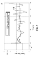
- FIG. 1 shows a graphical plot 10 of exemplary power oscillations in a power system.
- a horizontal axis 14 represents time in seconds whereas a vertical axis 12 represents power flow in a transmission line in per unit (pu).
- a curve 18 shows power oscillations in the transmission line power flow without a damping controller. Even though only power oscillations are shown here, it should be noted that the oscillations may be present in any other signal such as a voltage or a current or even a generator rotor speed.
- a power demand on the transmission line gets changed from 2 pu to around 3 pu at 10 seconds. At this transition, power oscillations in curve 18 starts and they increase slowly in amplitude. If these oscillations are not damped, the respective power network may become unstable and may result in a power blackout.
- a curve 16 shows power oscillations in the transmission line power flow with a damping device such as an AVR or a FACTS device.
- a damping controller is used along with the damping device, the power oscillations attenuate quickly, and the power flow settles down to meet the new demand in around 16 seconds.
- a spike around 10 seconds is the result of damping controller parameters and depends on a damping controller gain value.
- curve 18 may be split into multiple oscillation modes or sinusoidal components of different frequencies. Sinusoidal signals have a property that if two signals 180 degrees out of phase are added, the resultant signal amplitude becomes zero.
- ⁇ ⁇ ⁇ j ⁇ d
- damping natural frequency which describes how oscillations in the system decay after a disturbance.
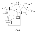
- FIG. 2 shows a power system 30 illustrating a system for damping oscillations in accordance with an embodiment of the present invention.
- Power system 30 includes generators 32, transmission lines 34, and load 36.
- Power system 30 further includes damping devices such as AVR 38 or FACTS device 40.
- AVR 38 can damp power system oscillations by controlling the excitation of generator 32 and thus, by controlling power flow from the generator based on an input from a damping controller 42.
- each of the generators 32 has an automatic voltage regulator (AVR) controlled by damping controller 42.
- AVR automatic voltage regulator
- FACTS device 40 can damp power system oscillations by either injecting or absorbing appropriate active and reactive power from the power system 30 based on an input from damping controller 42.
- damping devices may be used for other purposes apart from damping the oscillations.
- the AVR may be used to control a generator output voltage, but when a power system stabilizer (PSS) is used it will also serve the function of the damping device.
- PSS power
- Damping controller 42 receives measurement signals such as voltage or power signals at a point at which generator 32 or FACTS device 40 is connected to transmission line 34. It should be noted that even though damping controller 42 is shown as a central controller, in other embodiments a separate controller or a local controller may be used for AVR 38 and FACTS device 40. Damping controller 42 extracts signal components of different frequencies from the input signal and provides appropriate control signals to AVR 38 and FACTS device 40 to cancel out the extracted frequency components. In one embodiment, FACTS device 40 and AVR 38 may have their individual controllers (not shown) designed for a different purpose such as for reactive power compensation or voltage compensation and output from damping controller 42 is added to reference signals of the those individual controllers. Thus, the individual controller in addition to its main purpose also acts on command from damping controller 42 to damp the measurement signal oscillations.
- FIG. 3 shows a block diagram of an indirect adaptive controller for power oscillation damping (IACPOD) 70.
- IACPOD 70 is utilized to generate a control signal u(t) for a damping device 71 based on an output signal y(t) of a power network 75.
- IACPOD 70 may be employed in controller 42 of FIG.1 .
- IACPOD 70 includes an online estimator 72, a controller design module 74 for determining controller parameters for a controller module 76.
- Online estimator 72 estimates oscillation modes information in a power system comprising power network 75 and damping device 71, based on which controller design module 74 determines the controller parameters for controller module 76.
- the controller parameters are not updated directly, rather indirectly via the estimation of the system dynamics. This results in an indirect adaptive algorithm of IACPOD 70.
- Online estimator 72 includes a system model which estimates an output of a power system including the FACTs devices based on an input signal which may be a voltage signal, a current signal, a power signal or a speed signal, for example.
- the system model may include an auto regressive moving average (ARMA) model.
- y(t) and y(t-i) are output signals of the system model at a sample time t and (t-i) respectively
- v(t-k-i) is an input signal to the model at time (t-k-i)
- e(t) is a zero mean random noise with a Gaussian distribution
- a i and b i are auto regressive (AR) coefficients
- n a and n b are orders of a numerator and denominator polynomial of the power system model transfer function respectively.
- the output signal y(t) includes various electromechanical modes of power system oscillation.
- the power system model may be a very high order model i.e., the value of n a or number of poles in the power system model may be very high.
- ⁇ 0 is a constant with a value equal to 0.8.
- the system model generates the predicted output ⁇ (t) based on updated values in the regressor X(t) and the parameter vector ⁇ (t) and based on the predicted output ⁇ (t) inter-area oscillation modes of interest are detected.
- inter-area oscillation modes may range from 0.1 Hz to 1.0 Hz and local-mode oscillation mode may range from 1.0 Hz to 3.0 Hz.
- sampling time of sampling frequency may vary from 20 ms to 100 ms. In one embodiment of the present technique, a sampling time of 80 ms provided good results.
- controller 76 provides an appropriate control signal u(t) to damp these inter-area oscillation modes.
- controller 76 may include an adaptive controller and controller design module 74 utilizes a pole shifting control algorithm to compute the controller coefficients for controller 76.
- the controller parameters are derived by controller design module 74 based on the equality equation 10.
- D can be determined by solving above equality based on the value of the pole shifting factor ⁇ .
- ⁇ T (t) [-u(t-1),...,-u(t-n f ), -y(t), ..., -y(t-n g )] T .
- an optimization function based on a principle of a minimum variance (MV) regulator is used to determine an optimum value of pole shifting factor ⁇ .
- MV minimum variance
- J(t+1, ⁇ ) is an optimization function
- A is the absolute value of the largest root of A(z -1 )
- ⁇ is a security factor to account for the inaccuracy of the estimated parameters
- u min and u max are the maximum and minimum limits of the damping device respectively.
- the constraints are utilized to guarantee the stability of the closed-loop system.
- controller 76 Based on values of control parameters in vector D determined by controller design block 74, controller 76 generates a control signal which is provided to the damping device to generate the appropriate damping signal and therefore damp oscillations.
- controller design block 74 samples and stacks the input/output data in vector ⁇ (t) at a smaller sampling interval as compared to the online estimator 72.
- the sampling time for the controller design block 74 and controller 76 is designed to be 20 ms, thereby enabling the controller 76 to generate control input with more recent information about the system, Whereas the same set of model parameters as identified by the estimator 72 are used to generate u(t) till the next set of updated parameters that are available at an interval of 80 ms.
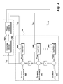
- FIG. 4 shows a block diagram of a damping controller 100 for damping power system oscillations in accordance with an embodiment of the present technique.
- Damping controller 100 is utilized with a damping device 102 which injects damping signals into a power network 104 for damping power oscillations in power network 104.
- Damping controller 100 further determines various power oscillation modes in power network 104 and provides a damping control signal to damping device 102 to damp the power oscillation modes.
- Damping controller 100 receives a plurality of feedback signals y 1 (t), y 2 (t), ..., y m (t) and includes a plurality of adaptive controllers or IACPODs 108 for each of those plurality of feedback signals.
- the plurality of feedback signals may be local power system measurement signals, remote power system measurement signals or combinations thereof.
- Each of IACPODs 108 has a structure similar to that of IACPOD 70 of Fig. 3 . However, IACPOD 70 ( Fig. 3 ) utilizes a single feedback input from power network 75 to determine all oscillation modes in the power network and generates a single control signal that tries to compensate for all those oscillation modes. On the contrary, each of IACPOD 108 in Fig.
- IACPOD 108 forms an outer closed loop path and determines an individual oscillation mode from an appropriate feedback signal.
- the feedback signal selection is done based on the dominance of the oscillation modes present in the feedback signal.
- a residue magnitude-angle method may be used offline to select the appropriate feedback signal.
- IACPOD 108 further provides an adaptive control signal to compensate for that specific oscillation mode by shifting an open loop pole of its inner loop path related to the individual oscillation mode to a closed loop location.
- damping controller 100 of FIG. 4 includes a multiple Single-input Single output (multi SISO) IACPODs. The number of IADPODs 108 that are used in damping controller 108 depends on number oscillation modes that need to be compensated.
- each IACPOD 108 first determines and then shifts an open-loop pole of the power system comprising power network 104 and damping device 102 to a desired closed loop location.
- a third-order system model is used in each IACPOD 108 which provides a damping control signal based on at least one feedback signal y(t) from power network 104 and at least one control signal u m (t) from damping controller 100 superimposed with a Gaussian white noise 107 to produce a control signal u(m-1) and achieves a desired damping ratio one at a time. Every outer loop with the IACPOD 108 identifies an open loop system with one poorly damped pole already shifted by previous IACPOD.
- damping control signals u 1 (t), u 2 (t), ..., u m (t) generated by IACPODs 108 are time delayed by a time sample with respect to one another to provide an individual control action in case simultaneous control actions to damp oscillations are not desired.
- a plurality of delay blocks 110 is utilized to delay the damping control signals.
- a time delay involved to delay the damping control signals is equal to the sampling interval of the controller.
- the damping control signal u(t) that is provided to damping device 102 is an addition of all delayed control actions u 1 (t), u 2 (t), ..., u m (t) and Gaussian white noises 107.
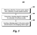
- FIG. 5 shows a method 200 of damping power system oscillations in accordance with an embodiment of the present technique.
- Method 200 includes obtaining a plurality of power system measurement signals from a plurality of power system locations in step 202.
- the plurality of power system measurement signals may be local or remote or combinations thereof.
- the method 200 includes generating a damping control signal to compensate for a plurality of oscillation modes in the power system oscillations.
- generating the damping control signal comprises extracting an individual oscillation mode from each of the power system measurement signals for a plurality of oscillation modes in the power system oscillations and generating a plurality of adaptive control signals to shift open loop poles related to the individual oscillation modes to a closed loop location.
- step 206 method 200 includes injecting a damping signal in the power system network based on the damping control signal.
Landscapes
- Engineering & Computer Science (AREA)
- Medical Informatics (AREA)
- Health & Medical Sciences (AREA)
- Artificial Intelligence (AREA)
- Computer Vision & Pattern Recognition (AREA)
- Evolutionary Computation (AREA)
- Software Systems (AREA)
- Physics & Mathematics (AREA)
- General Physics & Mathematics (AREA)
- Automation & Control Theory (AREA)
- Power Engineering (AREA)
- Supply And Distribution Of Alternating Current (AREA)
- Feedback Control In General (AREA)
Abstract
Description
- Embodiments of the present invention relate generally to a power flow in a power system. More specifically, the embodiments relate to damping of power system oscillations.
- The power system is a complex network comprising of numerous generators, transmission lines, a variety of loads and transformers. With increasing power demand in the power system, some transmission lines are more stressed than was planned when they were built. Since stressed conditions can lead a system to unstable conditions, power system stability has become an important issue. In simple terms, power system stability is defined as the ability of the power system to return to a normal state after a disturbance. The disturbance may be a fault, a loss of a generator or even a sudden increase in power loading which results in power oscillations in power system.
- Small signal stability is a power system stability issue related to low frequency oscillations between generator rotors. It has been the main reason for many power blackouts across the world including the Western Electricity Co-ordination Council (WECC) blackout of 1996. When the power system is heavily loaded, it often exhibits multi-mode oscillations because machine rotors, behaving as rigid bodies, oscillate with respect to one another using the electrical transmission lines between them to exchange energy. These oscillations generally lie in a frequency range between 0.1-3 Hz. The oscillations in this frequency range are generally analyzed in two main oscillation modes: 1) a local mode in the range of 1 to 3 Hz i.e., a generator or a group of generators in a plant swinging against the rest of the system and 2) an inter area mode in the range of 0.1 to 1 Hz i.e., machines in one group oscillate against machines in another group.
- To stabilize the power system, damping measures to damp the power oscillations are utilized. Power system stabilizers (PSSs) are the most common damping control devices in power systems. Apart from PSSs, power oscillation damping (POD) can be effectively achieved through supplementary control of Flexible AC Transmission Systems (FACTS) devices installed in key transmission corridors. Traditionally, classical control theory has been adopted for design of such controllers which require an accurate model of the system at a particular (nominal) operating condition. However, lack of availability of accurate and updated information about each and every dynamic component of a large inter-connected system and its ever changing nature often puts a fundamental challenge on such model based approaches. Indirect adaptive controllers, which rely solely on system measurements, are useful for power system stabilizers (PSS) and also for the FACTS devices. These controllers are updated online based on the estimated model of the system and thus can adapt to the changes in operating conditions. However, present architectures of indirect adaptive controllers utilize complex multi-input multi-output (MIMO) structure. This leads to a multivariable controller, which is very complicated in nature.
- For these and other reasons, there is a need for an improved indirect adaptive controller for power oscillation damping.
- In accordance with an embodiment of the present technique, a system for damping power system oscillations is provided. The system includes a damping device controller to generate a damping control signal to compensate for a plurality of oscillation modes in the power system oscillations. The damping device controller includes a plurality of outer closed loop paths each including an adaptive controller configured to determine an individual oscillation mode from at least one power system measurement signal. Each adaptive controller is further configured to generate an adaptive control signal to shift at least one open loop pole of an inner loop path related to the individual oscillation mode to a closed loop location. The system further includes a damping device to generate a damping signal based on the damping control signal.
- In accordance with another embodiment of the present technique, a method of damping power system oscillations in a power system network is provided. The method includes obtaining a plurality of power system measurement signals from a plurality of power system locations and generating a damping control signal to compensate for a plurality of oscillation modes in the power system oscillations. In the method, generating the damping control signal includes extracting an individual oscillation mode from each of the power system measurement signals generating a plurality of adaptive control signals to shift open loop poles related to the individual oscillation modes to a closed loop location. The method further includes injecting a damping signal in the power system network based on the control signal.
- These and other features, aspects, and advantages of the present invention will become better understood when the following detailed description is read with reference to the accompanying drawings in which like characters represent like parts throughout the drawings, wherein:
-
FIG. 1 is a graphical representation of exemplary power oscillations in a power system; -
FIG. 2 is a schematic diagram of a power system illustrating a system for damping power system oscillations in accordance with an embodiment of the present technique; -
FIG. 3 is a block diagram of an indirect adaptive controller for power oscillation damping (IACPOD); -
FIG. 4 is a block diagram of a damping controller for damping power system oscillations in accordance with an embodiment of the present technique; and -
FIG. 5 is a flow chart illustrating a method of damping power system oscillations in accordance with an embodiment of the present technique. - As used herein, the term "controller" refers to software, hardware, or firmware, or any combination of these, or any system, process, or functionality that performs or facilitates the processes described herein.
- When introducing elements of various embodiments of the present invention, the articles "a," "an," "the," and "said" are intended to mean that there are one or more of the elements. The terms "comprising," "including," and "having" are intended to be inclusive and mean that there may be additional elements other than the listed elements.
-
FIG. 1 shows agraphical plot 10 of exemplary power oscillations in a power system. Ahorizontal axis 14 represents time in seconds whereas avertical axis 12 represents power flow in a transmission line in per unit (pu). Acurve 18 shows power oscillations in the transmission line power flow without a damping controller. Even though only power oscillations are shown here, it should be noted that the oscillations may be present in any other signal such as a voltage or a current or even a generator rotor speed. A power demand on the transmission line gets changed from 2 pu to around 3 pu at 10 seconds. At this transition, power oscillations incurve 18 starts and they increase slowly in amplitude. If these oscillations are not damped, the respective power network may become unstable and may result in a power blackout. - A
curve 16 shows power oscillations in the transmission line power flow with a damping device such as an AVR or a FACTS device. As can be seen, when a damping controller is used along with the damping device, the power oscillations attenuate quickly, and the power flow settles down to meet the new demand in around 16 seconds. A spike around 10 seconds is the result of damping controller parameters and depends on a damping controller gain value. Also based on Fourier series principles, it can be seen thatcurve 18 may be split into multiple oscillation modes or sinusoidal components of different frequencies. Sinusoidal signals have a property that if two signals 180 degrees out of phase are added, the resultant signal amplitude becomes zero. In control theory the sinusoidal signal may be represented in terms of a eigenvalue λ which may be given as:
where σ may be referred as a damping ratio and ωd may be referred as damping natural frequency which describes how oscillations in the system decay after a disturbance. However, determining exact values of σ and ωd may not be feasible. Thus, in one embodiment, a closed loop system is employed which determines approximate factors σ and ωd so as to minimize an oscillation signal or an oscillation mode. -
FIG. 2 shows apower system 30 illustrating a system for damping oscillations in accordance with an embodiment of the present invention.Power system 30 includesgenerators 32,transmission lines 34, andload 36.Power system 30 further includes damping devices such as AVR 38 orFACTS device 40.AVR 38 can damp power system oscillations by controlling the excitation ofgenerator 32 and thus, by controlling power flow from the generator based on an input from adamping controller 42. In other embodiments, each of thegenerators 32 has an automatic voltage regulator (AVR) controlled bydamping controller 42. Similarly,FACTS device 40 can damp power system oscillations by either injecting or absorbing appropriate active and reactive power from thepower system 30 based on an input fromdamping controller 42. Further, damping devices may be used for other purposes apart from damping the oscillations. For example, the AVR may be used to control a generator output voltage, but when a power system stabilizer (PSS) is used it will also serve the function of the damping device. -
Damping controller 42 receives measurement signals such as voltage or power signals at a point at whichgenerator 32 orFACTS device 40 is connected totransmission line 34. It should be noted that even thoughdamping controller 42 is shown as a central controller, in other embodiments a separate controller or a local controller may be used for AVR 38 andFACTS device 40. Dampingcontroller 42 extracts signal components of different frequencies from the input signal and provides appropriate control signals toAVR 38 andFACTS device 40 to cancel out the extracted frequency components. In one embodiment,FACTS device 40 andAVR 38 may have their individual controllers (not shown) designed for a different purpose such as for reactive power compensation or voltage compensation and output from dampingcontroller 42 is added to reference signals of the those individual controllers. Thus, the individual controller in addition to its main purpose also acts on command from dampingcontroller 42 to damp the measurement signal oscillations. -
FIG. 3 shows a block diagram of an indirect adaptive controller for power oscillation damping (IACPOD) 70.IACPOD 70 is utilized to generate a control signal u(t) for a dampingdevice 71 based on an output signal y(t) of apower network 75.IACPOD 70 may be employed incontroller 42 ofFIG.1 .IACPOD 70 includes anonline estimator 72, acontroller design module 74 for determining controller parameters for acontroller module 76.Online estimator 72 estimates oscillation modes information in a power system comprisingpower network 75 and dampingdevice 71, based on whichcontroller design module 74 determines the controller parameters forcontroller module 76. Thus, the controller parameters are not updated directly, rather indirectly via the estimation of the system dynamics. This results in an indirect adaptive algorithm ofIACPOD 70. -
Online estimator 72 includes a system model which estimates an output of a power system including the FACTs devices based on an input signal which may be a voltage signal, a current signal, a power signal or a speed signal, for example. In one embodiment, the system model may include an auto regressive moving average (ARMA) model. In one embodiment, a power system model output may be represented as:
where y(t) and y(t-i) are output signals of the system model at a sample time t and (t-i) respectively, v(t-k-i) is an input signal to the model at time (t-k-i), e(t) is a zero mean random noise with a Gaussian distribution, ai and bi are auto regressive (AR) coefficients and na and nb are orders of a numerator and denominator polynomial of the power system model transfer function respectively. The output signal y(t) includes various electromechanical modes of power system oscillation. It should be noted that the above system model equation is in time domain and in z-domain, the equation may be represented as:
where,

- In general, at every sample, a predicted output ŷ(t) of system model is determined which in an embodiment is given as:

where X(t) is a regressor comprising past input and output samples, i.e., X(t)=[-y(t-1), ...-y(t-na), u(t-1), ...u(t-nb)]T and θ̂(t-1) is a parameter vector at a previous sample i.e., at time (t-1) comprising ARMA coefficients or system parameters, i.e., θ̂ = [â 0 , â 1, .... âna, b̂ 0 ,b̂1, .... b̂nb ]T at any given time e.g., at (t-1) in the present instant. The parameter vector θ̂ is updated at every sample and is determined by:
where ε(t) is a prediction error given by:
and K(t) is a gain vector given as:
- In equation (7) above, λ is a forgetting factor and P is a covariance matrix and at sample time equal to t are given as:


- In an embodiment, ∑0 is a constant with a value equal to 0.8. Thus, at every sample, the system model generates the predicted output ŷ(t) based on updated values in the regressor X(t) and the parameter vector θ̂(t) and based on the predicted output ŷ(t) inter-area oscillation modes of interest are detected. In an embodiment, inter-area oscillation modes may range from 0.1 Hz to 1.0 Hz and local-mode oscillation mode may range from 1.0 Hz to 3.0 Hz.
- It should be noted that the appropriate identification of the oscillation mode of interest from the predicted output ŷ(t) depends on the choice of sampling frequency. The sampling time of sampling frequency may vary from 20 ms to 100 ms. In one embodiment of the present technique, a sampling time of 80 ms provided good results.
- Referring back to
FIG. 3 , once theonline estimator 72 determines the inter-area oscillation modes of interest,controller 76 provides an appropriate control signal u(t) to damp these inter-area oscillation modes. In an embodiment,controller 76 may include an adaptive controller andcontroller design module 74 utilizes a pole shifting control algorithm to compute the controller coefficients forcontroller 76. In one embodiment, a feedback control loop has the form:
where,


- The controller parameters are derived by
controller design module 74 based on theequality equation 10. For example, let D be a matrix of control parameter gi and fi, i.e., D=[f1, f2,..., .fnf, go, g1, ... ., gngf ]T, then D can be determined by solving above equality based on the value of the pole shifting factor α. The control signal u(t) which will compensate for the inter-area oscillation mode of the interest can then be expressed as:
where ξT(t)=[-u(t-1),...,-u(t-nf), -y(t), ..., -y(t-ng)]T. In one embodiment, an optimization function based on a principle of a minimum variance (MV) regulator is used to determine an optimum value of pole shifting factor α. In this method, a system output in the next sample is predicted from the following equation:
where β =[-b2, -b3, , bnfb, a1, a2, .... , ana]T. Thus, the optimization problem becomes
subject to constraints
where, as discussed above ŷ(t+1) is the expected output and yr(t+1) is a desired output at the next sampling instant. J(t+1, α) is an optimization function, A is the absolute value of the largest root of A(z-1), σ is a security factor to account for the inaccuracy of the estimated parameters and umin and umax are the maximum and minimum limits of the damping device respectively. The constraints are utilized to guarantee the stability of the closed-loop system. - Thus, based on values of control parameters in vector D determined by
controller design block 74,controller 76 generates a control signal which is provided to the damping device to generate the appropriate damping signal and therefore damp oscillations. In one embodiment,controller design block 74 samples and stacks the input/output data in vector ξ(t) at a smaller sampling interval as compared to theonline estimator 72. For example, the sampling time for thecontroller design block 74 andcontroller 76 is designed to be 20 ms, thereby enabling thecontroller 76 to generate control input with more recent information about the system, Whereas the same set of model parameters as identified by theestimator 72 are used to generate u(t) till the next set of updated parameters that are available at an interval of 80 ms. -
FIG. 4 shows a block diagram of a dampingcontroller 100 for damping power system oscillations in accordance with an embodiment of the present technique. Dampingcontroller 100 is utilized with a dampingdevice 102 which injects damping signals into apower network 104 for damping power oscillations inpower network 104. Dampingcontroller 100 further determines various power oscillation modes inpower network 104 and provides a damping control signal to dampingdevice 102 to damp the power oscillation modes. - Damping
controller 100 receives a plurality of feedback signals y1(t), y2(t), ..., ym(t) and includes a plurality of adaptive controllers orIACPODs 108 for each of those plurality of feedback signals. The plurality of feedback signals may be local power system measurement signals, remote power system measurement signals or combinations thereof. Each ofIACPODs 108 has a structure similar to that of IACPOD 70 ofFig. 3 . However, IACPOD 70 (Fig. 3 ) utilizes a single feedback input frompower network 75 to determine all oscillation modes in the power network and generates a single control signal that tries to compensate for all those oscillation modes. On the contrary, each ofIACPOD 108 inFig. 4 forms an outer closed loop path and determines an individual oscillation mode from an appropriate feedback signal. In one embodiment, the feedback signal selection is done based on the dominance of the oscillation modes present in the feedback signal. In one embodiment, a residue magnitude-angle method may be used offline to select the appropriate feedback signal.IACPOD 108 further provides an adaptive control signal to compensate for that specific oscillation mode by shifting an open loop pole of its inner loop path related to the individual oscillation mode to a closed loop location. In other words, dampingcontroller 100 ofFIG. 4 includes a multiple Single-input Single output (multi SISO) IACPODs. The number ofIADPODs 108 that are used in dampingcontroller 108 depends on number oscillation modes that need to be compensated. - In damping
controller 100, eachIACPOD 108 first determines and then shifts an open-loop pole of the power system comprisingpower network 104 and dampingdevice 102 to a desired closed loop location. In one embodiment, a third-order system model is used in eachIACPOD 108 which provides a damping control signal based on at least one feedback signal y(t) frompower network 104 and at least one control signal um(t) from dampingcontroller 100 superimposed with a Gaussian white noise 107 to produce a control signal u(m-1) and achieves a desired damping ratio one at a time. Every outer loop with theIACPOD 108 identifies an open loop system with one poorly damped pole already shifted by previous IACPOD. In other words, every additional outer loop with oneIACPOD 108 identifies and shifts another poorly-damped mode and thus, multiple modes are damped together by dampingcontroller 100. In one embodiment, damping control signals u1(t), u2(t), ..., um(t) generated byIACPODs 108 are time delayed by a time sample with respect to one another to provide an individual control action in case simultaneous control actions to damp oscillations are not desired. In one embodiment, a plurality of delay blocks 110 is utilized to delay the damping control signals. In one embodiment, a time delay involved to delay the damping control signals is equal to the sampling interval of the controller. Finally, the damping control signal u(t) that is provided to dampingdevice 102 is an addition of all delayed control actions u1(t), u2(t), ..., um(t) and Gaussian white noises 107. -
FIG. 5 shows amethod 200 of damping power system oscillations in accordance with an embodiment of the present technique.Method 200 includes obtaining a plurality of power system measurement signals from a plurality of power system locations instep 202. The plurality of power system measurement signals may be local or remote or combinations thereof. Instep 204, themethod 200 includes generating a damping control signal to compensate for a plurality of oscillation modes in the power system oscillations. Furthermore, generating the damping control signal comprises extracting an individual oscillation mode from each of the power system measurement signals for a plurality of oscillation modes in the power system oscillations and generating a plurality of adaptive control signals to shift open loop poles related to the individual oscillation modes to a closed loop location. Finally, instep 206,method 200 includes injecting a damping signal in the power system network based on the damping control signal. - While only certain features of embodiments of the invention have been illustrated and described herein, many modifications and changes will occur to those skilled in the art. It is, therefore, to be understood that it is intended to cover all such modifications and changes as fall within the scope of the invention as defined in the appended claims.
- Various aspects and embodiments of the present invention are defined by the following numbered clauses:
- 1. A system for damping power system oscillations comprising:
- a damping device controller to generate a damping control signal to compensate for a plurality of oscillation modes in the power system oscillations, the damping device controller comprising:
- a plurality of outer closed loop paths each including an adaptive controller configured to determine an individual oscillation mode from at least one power system measurement signal;
- wherein each adaptive controller is further configured to generate an adaptive control signal to shift at least one open loop pole of an inner loop path related to the individual oscillation mode to a closed loop location; and
- a damping device to generate a damping signal based on the damping control signal.
- a damping device controller to generate a damping control signal to compensate for a plurality of oscillation modes in the power system oscillations, the damping device controller comprising:
- 2. The system of
clause 1, wherein the damping control signal is generated by a summation of adaptive control signals, wherein each additional adaptive control signal is delayed by a sample time with respect to the previous adaptive control signal prior to the summation. - 3. The system of any preceding clause, wherein each additional adaptive control signal is superimposed with a Gaussian white noise before delaying by the sample time.
- 4. The system of any preceding clause, wherein the damping device includes automatic voltage regulator (AVR) or a flexible alternating current transmission system (FACTS) device.
- 5. The system of any preceding clause, wherein the power system measurement signal comprises a voltage signal, a current signal, a power signal, or a speed signal.
- 6. The system of any preceding clause, wherein the power system measurement signal comprises a remote power system measurement signals or a local power system measurement signal.
- 7. The system of any preceding clause, wherein the adaptive controller comprises an online estimator model for determining the individual oscillation mode from the power system measurement signal.
- 8. The system of any preceding clause, wherein the online estimator model comprises an auto regressive moving average model.
- 9. The system of any preceding clause, wherein the adaptive controller comprises a controller design module to determine controller parameters.
- 10. The system of any preceding clause, wherein the controller design module includes a pole shifting control algorithm to shift the open loop pole of the inner loop path by a pole shifting factor.
- 11. The system of any preceding clause, wherein the controller parameters are determined based on an equality equation comprising a closed loop characteristics equation.
- 12. The system of any preceding clause, wherein a number of the plurality of adaptive controllers is equal to a number of oscillation modes that need to be compensated for the power system oscillation damping.
- 13. A method of damping power system oscillations in a power system network, the method comprising:
- obtaining a plurality of power system measurement signals from a plurality of power system locations;
- generating a damping control signal to compensate for a plurality of oscillation modes in the power system oscillations, wherein generating the damping control signal comprises:
- extracting an individual oscillation mode from each of the power system measurement signals;
- generating a plurality of adaptive control signals to shift open loop poles related to the individual oscillation modes to a closed loop location; and
- injecting a damping signal in the power system network based on the control signal.
- 14. The method of any preceding clause, wherein generating the damping control signal comprises adding the adaptive control signals, wherein each additional adaptive control signal is delayed by a sample time with respect to the previous adaptive control signal prior to the addition.
- 15. The method of any preceding clause, wherein each additional adaptive control signal is superimposed with a Gaussian white noise before delaying by the sample time.
- 16. The method of any preceding clause, wherein injecting the damping signal includes utilizing an automatic voltage regulator (AVR) or a flexible alternating current transmission system (FACTS) device.
- 17. The method of any preceding clause, wherein the plurality of power system measurement signals comprises voltage signals, current signals, power signals, speed signals or combinations thereof.
- 18. The method of any preceding clause, wherein generating a plurality of adaptive control signals comprises utilizing a pole shifting control algorithm to shift the open loop poles related to the oscillation modes by a pole shifting factor.
- 19. The method of any preceding clause, wherein the pole shifting factor is determined based on an optimization function comprising minimizing an error between an expected output and a desired output.
- 20. The method of any preceding clause, wherein a number of the plurality of adaptive control signals is equal to a number of oscillation modes that need to be compensated for damping the power system oscillations.
Claims (15)
- A system (30) for damping power system oscillations comprising:a damping device controller (100) to generate a damping control signal to compensate for a plurality of oscillation modes in the power system oscillations, the damping device controller (100) comprising:a plurality of outer closed loop paths each including an adaptive controller (108) configured to determine an individual oscillation mode from at least one power system measurement signal;wherein each adaptive controller (108) is further configured to generate an adaptive control signal to shift at least one open loop pole of an inner loop path related to the individual oscillation mode to a closed loop location; anda damping device (102) to generate a damping signal based on the damping control signal.
- The system of claim 1, wherein the damping control signal is generated by a summation of adaptive control signals, wherein each additional adaptive control signal is delayed by a sample time with respect to the previous adaptive control signal prior to the summation.
- The system of claim 1 or claim 2, wherein each additional adaptive control signal is superimposed with a Gaussian white noise before delaying by the sample time.
- The system of claim 1, 2 or 3, wherein the damping device (102) includes automatic voltage regulator (AVR) (38) or a flexible alternating current transmission system (FACTS) device (40).
- The system of any preceding claim, wherein the power system measurement signal comprises a voltage signal, a current signal, a power signal, or a speed signal.
- The system of any preceding claim, wherein the power system measurement signal comprises a remote power system measurement signals or a local power system measurement signal.
- The system of any preceding claim, wherein the adaptive controller (108) comprises an online estimator model (72) for determining the individual oscillation mode from the power system measurement signal.
- The system of any preceding claim, wherein the online estimator model (72) comprises an auto regressive moving average model.
- The system of claim 1, wherein the adaptive controller (108) comprises a controller design module (74) to determine controller parameters.
- The system of claim 9, wherein the controller design module (74) includes a pole shifting control algorithm to shift the open loop pole of the inner loop path by a pole shifting factor.
- The system of any preceding claim, wherein the controller parameters are determined based on an equality equation comprising a closed loop characteristics equation.
- The system of any preceding claim, wherein a number of the plurality of adaptive controllers (108) is equal to a number of oscillation modes that need to be compensated for the power system oscillation damping.
- A method (200) of damping power system oscillations in a power system network, the method comprising:obtaining (202) a plurality of power system measurement signals from a plurality of power system locations;generating (204) a damping control signal to compensate for a plurality of oscillation modes in the power system oscillations, wherein generating the damping control signal comprises:extracting an individual oscillation mode from each of the power system measurement signals;generating a plurality of adaptive control signals to shift open loop poles related to the individual oscillation modes to a closed loop location; andinjecting (206) a damping signal in the power system network based on the control signal.
- The method of claim 13, wherein generating (204) the damping control signal comprises adding the adaptive control signals, wherein each additional adaptive control signal is delayed by a sample time with respect to the previous adaptive control signal prior to the addition.
- The method of claim 13 or claim 14, wherein generating a plurality of adaptive control signals comprises utilizing a pole shifting control algorithm to shift the open loop poles related to the oscillation modes by a pole shifting factor, and wherein, preferably, the pole shifting factor is determined based on an optimization function comprising minimizing an error between an expected output and a desired output.
Applications Claiming Priority (1)
| Application Number | Priority Date | Filing Date | Title |
|---|---|---|---|
| US13/905,415 US9385533B2 (en) | 2013-05-30 | 2013-05-30 | Power system stabilization |
Publications (3)
| Publication Number | Publication Date |
|---|---|
| EP2808970A2 true EP2808970A2 (en) | 2014-12-03 |
| EP2808970A3 EP2808970A3 (en) | 2015-04-08 |
| EP2808970B1 EP2808970B1 (en) | 2017-07-12 |
Family
ID=50980113
Family Applications (1)
| Application Number | Title | Priority Date | Filing Date |
|---|---|---|---|
| EP14168845.7A Not-in-force EP2808970B1 (en) | 2013-05-30 | 2014-05-19 | Power system stabilization |
Country Status (8)
| Country | Link |
|---|---|
| US (1) | US9385533B2 (en) |
| EP (1) | EP2808970B1 (en) |
| JP (1) | JP6291351B2 (en) |
| CN (1) | CN104218594B (en) |
| BR (1) | BR102014011862A2 (en) |
| CA (1) | CA2851966C (en) |
| IN (1) | IN2014CH02463A (en) |
| MX (1) | MX338242B (en) |
Cited By (1)
| Publication number | Priority date | Publication date | Assignee | Title |
|---|---|---|---|---|
| CN105262118A (en) * | 2015-11-20 | 2016-01-20 | 江苏省电力公司电力经济技术研究院 | STATCOM-based subsynchronous oscillation suppression method and control device for STATCOM |
Families Citing this family (10)
| Publication number | Priority date | Publication date | Assignee | Title |
|---|---|---|---|---|
| CN105305467B (en) * | 2015-10-12 | 2017-12-29 | 华北电力大学 | Suppress the capacity estimation method of the parallel connection type FACTS devices of sub-synchronous oscillation |
| CN105449696B (en) * | 2015-11-18 | 2018-04-13 | 国家电网公司 | A kind of more damping controller segmented co-design methods of THE UPFC |
| CN105356472B (en) * | 2015-11-20 | 2018-04-13 | 华南理工大学 | Online frequency synthesis control method based on source lotus characteristic |
| CN106786675B (en) * | 2017-02-14 | 2021-09-03 | 中国电力科学研究院 | Power system stabilizer and implementation method thereof |
| US10983150B2 (en) * | 2017-08-28 | 2021-04-20 | General Electric Technology Gmbh | Systems and methods for detecting and evaluating oscillations in an electrical power grid |
| CN113037088B (en) * | 2019-12-24 | 2022-08-09 | 航天科工惯性技术有限公司 | DAB converter input end current oscillation suppression method and device |
| US11637428B2 (en) * | 2020-09-29 | 2023-04-25 | Mitsubishi Electric Power Products, Inc. | Selective power oscillation damping control system with damping ratio dynamic gain and method for the same |
| US11894681B2 (en) | 2021-10-01 | 2024-02-06 | General Electric Company | System and method for power oscillation damping in a power generating system |
| CN114046869B (en) * | 2021-11-16 | 2022-07-08 | 河海大学 | Broadband oscillation information online monitoring method and system based on daily disturbance response of power system |
| CN116316705B (en) | 2023-04-14 | 2023-09-12 | 长沙学院 | Low-carbon power system oscillation suppression method based on energy storage power station |
Family Cites Families (14)
| Publication number | Priority date | Publication date | Assignee | Title |
|---|---|---|---|---|
| JP3304664B2 (en) * | 1994-02-17 | 2002-07-22 | 株式会社日立製作所 | Power system stabilization control device and power system stabilization control method |
| JPH08191543A (en) * | 1995-01-09 | 1996-07-23 | Mitsubishi Electric Corp | Power fluctuation suppression control device |
| EP1737098A1 (en) | 2005-06-24 | 2006-12-27 | Abb Research Ltd. | Damping electromagnetic oscillations in power system |
| EP2022154B1 (en) | 2006-05-30 | 2015-10-14 | Abb Research Ltd. | Thyristor controlled series capacitor adapted to damp sub synchronous resonances |
| RU2461944C2 (en) * | 2007-03-28 | 2012-09-20 | Абб Рисерч Лтд | Damping of electro-magnetic oscillations in power supply systems |
| EP2124311A1 (en) * | 2008-05-23 | 2009-11-25 | ABB Research LTD | Time delay compensation in power system control |
| BRPI0924856B8 (en) * | 2009-06-11 | 2022-11-01 | Abb Research Ltd | METHOD FOR PROVIDING CONTROL OF A POWER TRANSMISSION SYSTEM AND POWER CONTROL DEVICE |
| CN102474100B (en) * | 2009-08-06 | 2014-08-27 | Abb研究有限公司 | Power or voltage oscillation damping in a power transmission system |
| EP2299555A1 (en) | 2009-09-21 | 2011-03-23 | ABB Research Ltd. | Fault tolerant damping of electromechanical oscillations in power systems |
| EP2312719B1 (en) * | 2009-10-16 | 2012-08-01 | ABB Research Ltd. | Investigating timing reliability in relation to control of a power transmission system |
| EP2325968A1 (en) | 2009-11-18 | 2011-05-25 | ABB Research Ltd. | Tuning a power oscillation damping unit |
| KR20170126017A (en) | 2010-09-28 | 2017-11-15 | 지멘스 악티엔게젤샤프트 | Power oscillation damping by a converterbased power generation device |
| CN102185324A (en) * | 2011-04-25 | 2011-09-14 | 东北电力大学 | Measured-information-based power system low-frequency oscillation analysis method |
| US20130234680A1 (en) * | 2012-03-08 | 2013-09-12 | General Electric Company | Power system stabilization |
-
2013
- 2013-05-30 US US13/905,415 patent/US9385533B2/en active Active
-
2014
- 2014-05-15 CA CA2851966A patent/CA2851966C/en active Active
- 2014-05-16 BR BR102014011862A patent/BR102014011862A2/en not_active Application Discontinuation
- 2014-05-19 IN IN2463CH2014 patent/IN2014CH02463A/en unknown
- 2014-05-19 EP EP14168845.7A patent/EP2808970B1/en not_active Not-in-force
- 2014-05-23 JP JP2014106607A patent/JP6291351B2/en not_active Expired - Fee Related
- 2014-05-29 MX MX2014006482A patent/MX338242B/en active IP Right Grant
- 2014-05-30 CN CN201410239098.6A patent/CN104218594B/en not_active Expired - Fee Related
Non-Patent Citations (1)
| Title |
|---|
| None |
Cited By (1)
| Publication number | Priority date | Publication date | Assignee | Title |
|---|---|---|---|---|
| CN105262118A (en) * | 2015-11-20 | 2016-01-20 | 江苏省电力公司电力经济技术研究院 | STATCOM-based subsynchronous oscillation suppression method and control device for STATCOM |
Also Published As
| Publication number | Publication date |
|---|---|
| EP2808970A3 (en) | 2015-04-08 |
| CN104218594B (en) | 2018-04-06 |
| MX2014006482A (en) | 2015-03-04 |
| JP2014236665A (en) | 2014-12-15 |
| US9385533B2 (en) | 2016-07-05 |
| CA2851966C (en) | 2022-08-23 |
| MX338242B (en) | 2016-04-08 |
| EP2808970B1 (en) | 2017-07-12 |
| US20140354062A1 (en) | 2014-12-04 |
| CA2851966A1 (en) | 2014-11-30 |
| BR102014011862A2 (en) | 2016-01-26 |
| JP6291351B2 (en) | 2018-03-14 |
| IN2014CH02463A (en) | 2015-07-03 |
| CN104218594A (en) | 2014-12-17 |
Similar Documents
| Publication | Publication Date | Title |
|---|---|---|
| EP2808970B1 (en) | Power system stabilization | |
| Zhao et al. | Improved synergetic excitation control for transient stability enhancement and voltage regulation of power systems | |
| EP2297832B1 (en) | Time delay compensation in power system control | |
| Chaudhuri et al. | Wide-area power oscillation damping control in Nordic equivalent system | |
| Sahu et al. | Robust analysis and design of PID controlled AVR system using Pattern Search algorithm | |
| US9006933B2 (en) | Power system stabilization | |
| Darabian et al. | Predictive control strategy to improve stability of DFIG‐based wind generation connected to a large‐scale power system | |
| Milla et al. | Predictive optimized adaptive PSS in a single machine infinite bus | |
| Roy et al. | Nonlinear adaptive excitation controller design for multimachine power systems | |
| Khan et al. | Hybrid adaptive neuro-fuzzy B-spline--based SSSC damping control paradigm using online system identification | |
| Roy et al. | Robust Adaptive Sliding Mode Excitation Controller Design with External Disturbances for Synchronous Generators | |
| Ngamroo | An optimization technique of robust load frequency stabilizer for superconducting magnetic energy storage | |
| Ghahremani et al. | Joint improvement of system loadability and stability through a multi-stage planning of a upfc with a pmu-based supplementary damping control | |
| Chaudhuri et al. | Power oscillation damping control using wide-area signals: A case study on Nordic equivalent system | |
| Leon et al. | Optimization with constraints for excitation control in synchronous generators | |
| Fusco et al. | Self-tuning regulator design for nodal voltage waveform control in electrical power systems | |
| Ali | Analysis of sub-synchronous oscillations in wind power plants | |
| Guezmil et al. | High order sliding mode and an unknown input observers: Comparison with integral sliding mode control for induction machine drive | |
| Ray et al. | Differential evolution-swarm hybrid optimization based SVC controller for transient stability analysis in SMIB | |
| Ali et al. | Optimal tuning and placement of pod for ssci mitigation in dfig-based power system | |
| Abdelsalam et al. | A TSA-based consideration to design LQR auxiliary voltage control of DFIG | |
| Boersma et al. | Enhanced LMI-based damping control in power networks through a high voltage direct current line | |
| Ding et al. | Modal resonance index-enabled resonance area based dynamic interaction analysis and parameter optimization for PMSGs in multi-machine power system | |
| Shahriar et al. | Comparison of MPC and conventional control methods for the stability enhancement of UPFC connected SMIB system | |
| Awelewa | Development of Nonlinear Control Schemes for Electric Power System Stabilization |
Legal Events
| Date | Code | Title | Description |
|---|---|---|---|
| PUAI | Public reference made under article 153(3) epc to a published international application that has entered the european phase |
Free format text: ORIGINAL CODE: 0009012 |
|
| 17P | Request for examination filed |
Effective date: 20140519 |
|
| AK | Designated contracting states |
Kind code of ref document: A2 Designated state(s): AL AT BE BG CH CY CZ DE DK EE ES FI FR GB GR HR HU IE IS IT LI LT LU LV MC MK MT NL NO PL PT RO RS SE SI SK SM TR |
|
| AX | Request for extension of the european patent |
Extension state: BA ME |
|
| PUAL | Search report despatched |
Free format text: ORIGINAL CODE: 0009013 |
|
| AK | Designated contracting states |
Kind code of ref document: A3 Designated state(s): AL AT BE BG CH CY CZ DE DK EE ES FI FR GB GR HR HU IE IS IT LI LT LU LV MC MK MT NL NO PL PT RO RS SE SI SK SM TR |
|
| AX | Request for extension of the european patent |
Extension state: BA ME |
|
| RIC1 | Information provided on ipc code assigned before grant |
Ipc: G05B 13/02 20060101ALN20150305BHEP Ipc: H02J 3/24 20060101AFI20150305BHEP |
|
| R17P | Request for examination filed (corrected) |
Effective date: 20151008 |
|
| RBV | Designated contracting states (corrected) |
Designated state(s): AL AT BE BG CH CY CZ DE DK EE ES FI FR GB GR HR HU IE IS IT LI LT LU LV MC MK MT NL NO PL PT RO RS SE SI SK SM TR |
|
| GRAP | Despatch of communication of intention to grant a patent |
Free format text: ORIGINAL CODE: EPIDOSNIGR1 |
|
| RIC1 | Information provided on ipc code assigned before grant |
Ipc: G05B 13/02 20060101ALN20170203BHEP Ipc: H02J 3/24 20060101AFI20170203BHEP |
|
| RIC1 | Information provided on ipc code assigned before grant |
Ipc: G05B 13/02 20060101ALN20170222BHEP Ipc: H02J 3/24 20060101AFI20170222BHEP |
|
| INTG | Intention to grant announced |
Effective date: 20170314 |
|
| GRAS | Grant fee paid |
Free format text: ORIGINAL CODE: EPIDOSNIGR3 |
|
| GRAA | (expected) grant |
Free format text: ORIGINAL CODE: 0009210 |
|
| AK | Designated contracting states |
Kind code of ref document: B1 Designated state(s): AL AT BE BG CH CY CZ DE DK EE ES FI FR GB GR HR HU IE IS IT LI LT LU LV MC MK MT NL NO PL PT RO RS SE SI SK SM TR |
|
| REG | Reference to a national code |
Ref country code: GB Ref legal event code: FG4D |
|
| REG | Reference to a national code |
Ref country code: CH Ref legal event code: EP |
|
| REG | Reference to a national code |
Ref country code: AT Ref legal event code: REF Ref document number: 909171 Country of ref document: AT Kind code of ref document: T Effective date: 20170715 |
|
| REG | Reference to a national code |
Ref country code: IE Ref legal event code: FG4D |
|
| REG | Reference to a national code |
Ref country code: DE Ref legal event code: R096 Ref document number: 602014011646 Country of ref document: DE |
|
| REG | Reference to a national code |
Ref country code: SE Ref legal event code: TRGR |
|
| REG | Reference to a national code |
Ref country code: NL Ref legal event code: MP Effective date: 20170712 |
|
| REG | Reference to a national code |
Ref country code: LT Ref legal event code: MG4D |
|
| REG | Reference to a national code |
Ref country code: AT Ref legal event code: MK05 Ref document number: 909171 Country of ref document: AT Kind code of ref document: T Effective date: 20170712 |
|
| PG25 | Lapsed in a contracting state [announced via postgrant information from national office to epo] |
Ref country code: LT Free format text: LAPSE BECAUSE OF FAILURE TO SUBMIT A TRANSLATION OF THE DESCRIPTION OR TO PAY THE FEE WITHIN THE PRESCRIBED TIME-LIMIT Effective date: 20170712 Ref country code: FI Free format text: LAPSE BECAUSE OF FAILURE TO SUBMIT A TRANSLATION OF THE DESCRIPTION OR TO PAY THE FEE WITHIN THE PRESCRIBED TIME-LIMIT Effective date: 20170712 Ref country code: AT Free format text: LAPSE BECAUSE OF FAILURE TO SUBMIT A TRANSLATION OF THE DESCRIPTION OR TO PAY THE FEE WITHIN THE PRESCRIBED TIME-LIMIT Effective date: 20170712 Ref country code: NO Free format text: LAPSE BECAUSE OF FAILURE TO SUBMIT A TRANSLATION OF THE DESCRIPTION OR TO PAY THE FEE WITHIN THE PRESCRIBED TIME-LIMIT Effective date: 20171012 Ref country code: HR Free format text: LAPSE BECAUSE OF FAILURE TO SUBMIT A TRANSLATION OF THE DESCRIPTION OR TO PAY THE FEE WITHIN THE PRESCRIBED TIME-LIMIT Effective date: 20170712 Ref country code: NL Free format text: LAPSE BECAUSE OF FAILURE TO SUBMIT A TRANSLATION OF THE DESCRIPTION OR TO PAY THE FEE WITHIN THE PRESCRIBED TIME-LIMIT Effective date: 20170712 |
|
| PG25 | Lapsed in a contracting state [announced via postgrant information from national office to epo] |
Ref country code: PL Free format text: LAPSE BECAUSE OF FAILURE TO SUBMIT A TRANSLATION OF THE DESCRIPTION OR TO PAY THE FEE WITHIN THE PRESCRIBED TIME-LIMIT Effective date: 20170712 Ref country code: RS Free format text: LAPSE BECAUSE OF FAILURE TO SUBMIT A TRANSLATION OF THE DESCRIPTION OR TO PAY THE FEE WITHIN THE PRESCRIBED TIME-LIMIT Effective date: 20170712 Ref country code: ES Free format text: LAPSE BECAUSE OF FAILURE TO SUBMIT A TRANSLATION OF THE DESCRIPTION OR TO PAY THE FEE WITHIN THE PRESCRIBED TIME-LIMIT Effective date: 20170712 Ref country code: GR Free format text: LAPSE BECAUSE OF FAILURE TO SUBMIT A TRANSLATION OF THE DESCRIPTION OR TO PAY THE FEE WITHIN THE PRESCRIBED TIME-LIMIT Effective date: 20171013 Ref country code: IS Free format text: LAPSE BECAUSE OF FAILURE TO SUBMIT A TRANSLATION OF THE DESCRIPTION OR TO PAY THE FEE WITHIN THE PRESCRIBED TIME-LIMIT Effective date: 20171112 Ref country code: LV Free format text: LAPSE BECAUSE OF FAILURE TO SUBMIT A TRANSLATION OF THE DESCRIPTION OR TO PAY THE FEE WITHIN THE PRESCRIBED TIME-LIMIT Effective date: 20170712 Ref country code: BG Free format text: LAPSE BECAUSE OF FAILURE TO SUBMIT A TRANSLATION OF THE DESCRIPTION OR TO PAY THE FEE WITHIN THE PRESCRIBED TIME-LIMIT Effective date: 20171012 |
|
| REG | Reference to a national code |
Ref country code: DE Ref legal event code: R097 Ref document number: 602014011646 Country of ref document: DE |
|
| PG25 | Lapsed in a contracting state [announced via postgrant information from national office to epo] |
Ref country code: DK Free format text: LAPSE BECAUSE OF FAILURE TO SUBMIT A TRANSLATION OF THE DESCRIPTION OR TO PAY THE FEE WITHIN THE PRESCRIBED TIME-LIMIT Effective date: 20170712 Ref country code: CZ Free format text: LAPSE BECAUSE OF FAILURE TO SUBMIT A TRANSLATION OF THE DESCRIPTION OR TO PAY THE FEE WITHIN THE PRESCRIBED TIME-LIMIT Effective date: 20170712 Ref country code: RO Free format text: LAPSE BECAUSE OF FAILURE TO SUBMIT A TRANSLATION OF THE DESCRIPTION OR TO PAY THE FEE WITHIN THE PRESCRIBED TIME-LIMIT Effective date: 20170712 |
|
| PLBE | No opposition filed within time limit |
Free format text: ORIGINAL CODE: 0009261 |
|
| STAA | Information on the status of an ep patent application or granted ep patent |
Free format text: STATUS: NO OPPOSITION FILED WITHIN TIME LIMIT |
|
| REG | Reference to a national code |
Ref country code: FR Ref legal event code: PLFP Year of fee payment: 5 |
|
| PG25 | Lapsed in a contracting state [announced via postgrant information from national office to epo] |
Ref country code: SM Free format text: LAPSE BECAUSE OF FAILURE TO SUBMIT A TRANSLATION OF THE DESCRIPTION OR TO PAY THE FEE WITHIN THE PRESCRIBED TIME-LIMIT Effective date: 20170712 Ref country code: EE Free format text: LAPSE BECAUSE OF FAILURE TO SUBMIT A TRANSLATION OF THE DESCRIPTION OR TO PAY THE FEE WITHIN THE PRESCRIBED TIME-LIMIT Effective date: 20170712 Ref country code: SK Free format text: LAPSE BECAUSE OF FAILURE TO SUBMIT A TRANSLATION OF THE DESCRIPTION OR TO PAY THE FEE WITHIN THE PRESCRIBED TIME-LIMIT Effective date: 20170712 Ref country code: IT Free format text: LAPSE BECAUSE OF FAILURE TO SUBMIT A TRANSLATION OF THE DESCRIPTION OR TO PAY THE FEE WITHIN THE PRESCRIBED TIME-LIMIT Effective date: 20170712 |
|
| 26N | No opposition filed |
Effective date: 20180413 |
|
| PG25 | Lapsed in a contracting state [announced via postgrant information from national office to epo] |
Ref country code: SI Free format text: LAPSE BECAUSE OF FAILURE TO SUBMIT A TRANSLATION OF THE DESCRIPTION OR TO PAY THE FEE WITHIN THE PRESCRIBED TIME-LIMIT Effective date: 20170712 |
|
| REG | Reference to a national code |
Ref country code: CH Ref legal event code: PL |
|
| REG | Reference to a national code |
Ref country code: BE Ref legal event code: MM Effective date: 20180531 |
|
| PG25 | Lapsed in a contracting state [announced via postgrant information from national office to epo] |
Ref country code: MC Free format text: LAPSE BECAUSE OF FAILURE TO SUBMIT A TRANSLATION OF THE DESCRIPTION OR TO PAY THE FEE WITHIN THE PRESCRIBED TIME-LIMIT Effective date: 20170712 |
|
| REG | Reference to a national code |
Ref country code: IE Ref legal event code: MM4A |
|
| PG25 | Lapsed in a contracting state [announced via postgrant information from national office to epo] |
Ref country code: CH Free format text: LAPSE BECAUSE OF NON-PAYMENT OF DUE FEES Effective date: 20180531 Ref country code: LI Free format text: LAPSE BECAUSE OF NON-PAYMENT OF DUE FEES Effective date: 20180531 |
|
| PG25 | Lapsed in a contracting state [announced via postgrant information from national office to epo] |
Ref country code: LU Free format text: LAPSE BECAUSE OF NON-PAYMENT OF DUE FEES Effective date: 20180519 |
|
| PG25 | Lapsed in a contracting state [announced via postgrant information from national office to epo] |
Ref country code: IE Free format text: LAPSE BECAUSE OF NON-PAYMENT OF DUE FEES Effective date: 20180519 |
|
| PG25 | Lapsed in a contracting state [announced via postgrant information from national office to epo] |
Ref country code: BE Free format text: LAPSE BECAUSE OF NON-PAYMENT OF DUE FEES Effective date: 20180531 |
|
| PG25 | Lapsed in a contracting state [announced via postgrant information from national office to epo] |
Ref country code: MT Free format text: LAPSE BECAUSE OF NON-PAYMENT OF DUE FEES Effective date: 20180519 |
|
| PG25 | Lapsed in a contracting state [announced via postgrant information from national office to epo] |
Ref country code: TR Free format text: LAPSE BECAUSE OF FAILURE TO SUBMIT A TRANSLATION OF THE DESCRIPTION OR TO PAY THE FEE WITHIN THE PRESCRIBED TIME-LIMIT Effective date: 20170712 |
|
| PG25 | Lapsed in a contracting state [announced via postgrant information from national office to epo] |
Ref country code: PT Free format text: LAPSE BECAUSE OF FAILURE TO SUBMIT A TRANSLATION OF THE DESCRIPTION OR TO PAY THE FEE WITHIN THE PRESCRIBED TIME-LIMIT Effective date: 20170712 Ref country code: HU Free format text: LAPSE BECAUSE OF FAILURE TO SUBMIT A TRANSLATION OF THE DESCRIPTION OR TO PAY THE FEE WITHIN THE PRESCRIBED TIME-LIMIT; INVALID AB INITIO Effective date: 20140519 |
|
| PG25 | Lapsed in a contracting state [announced via postgrant information from national office to epo] |
Ref country code: CY Free format text: LAPSE BECAUSE OF FAILURE TO SUBMIT A TRANSLATION OF THE DESCRIPTION OR TO PAY THE FEE WITHIN THE PRESCRIBED TIME-LIMIT Effective date: 20170712 Ref country code: MK Free format text: LAPSE BECAUSE OF NON-PAYMENT OF DUE FEES Effective date: 20170712 |
|
| PG25 | Lapsed in a contracting state [announced via postgrant information from national office to epo] |
Ref country code: AL Free format text: LAPSE BECAUSE OF FAILURE TO SUBMIT A TRANSLATION OF THE DESCRIPTION OR TO PAY THE FEE WITHIN THE PRESCRIBED TIME-LIMIT Effective date: 20170712 |
|
| P01 | Opt-out of the competence of the unified patent court (upc) registered |
Effective date: 20230522 |
|
| PGFP | Annual fee paid to national office [announced via postgrant information from national office to epo] |
Ref country code: FR Payment date: 20230420 Year of fee payment: 10 Ref country code: DE Payment date: 20230419 Year of fee payment: 10 |
|
| PGFP | Annual fee paid to national office [announced via postgrant information from national office to epo] |
Ref country code: SE Payment date: 20230419 Year of fee payment: 10 |
|
| PGFP | Annual fee paid to national office [announced via postgrant information from national office to epo] |
Ref country code: GB Payment date: 20230420 Year of fee payment: 10 |
|
| REG | Reference to a national code |
Ref country code: DE Ref legal event code: R081 Ref document number: 602014011646 Country of ref document: DE Owner name: GENERAL ELECTRIC TECHNOLOGY GMBH, CH Free format text: FORMER OWNER: GENERAL ELECTRIC COMPANY, SCHENECTADY, NY, US |
|
| REG | Reference to a national code |
Ref country code: GB Ref legal event code: 732E Free format text: REGISTERED BETWEEN 20240222 AND 20240228 |
|
| REG | Reference to a national code |
Ref country code: DE Ref legal event code: R119 Ref document number: 602014011646 Country of ref document: DE |
|
| REG | Reference to a national code |
Ref country code: SE Ref legal event code: EUG |
|
| GBPC | Gb: european patent ceased through non-payment of renewal fee |
Effective date: 20240519 |
|
| PG25 | Lapsed in a contracting state [announced via postgrant information from national office to epo] |
Ref country code: DE Free format text: LAPSE BECAUSE OF NON-PAYMENT OF DUE FEES Effective date: 20241203 |
|
| PG25 | Lapsed in a contracting state [announced via postgrant information from national office to epo] |
Ref country code: FR Free format text: LAPSE BECAUSE OF NON-PAYMENT OF DUE FEES Effective date: 20240531 |
|
| PG25 | Lapsed in a contracting state [announced via postgrant information from national office to epo] |
Ref country code: GB Free format text: LAPSE BECAUSE OF NON-PAYMENT OF DUE FEES Effective date: 20240519 |
|
| PG25 | Lapsed in a contracting state [announced via postgrant information from national office to epo] |
Ref country code: SE Free format text: LAPSE BECAUSE OF NON-PAYMENT OF DUE FEES Effective date: 20240520 |