EP2808934A1 - Power storage apparatus and method of operating power storage apparatus - Google Patents
Power storage apparatus and method of operating power storage apparatus Download PDFInfo
- Publication number
- EP2808934A1 EP2808934A1 EP12866796.1A EP12866796A EP2808934A1 EP 2808934 A1 EP2808934 A1 EP 2808934A1 EP 12866796 A EP12866796 A EP 12866796A EP 2808934 A1 EP2808934 A1 EP 2808934A1
- Authority
- EP
- European Patent Office
- Prior art keywords
- chamber
- battery
- electric cell
- air
- sealed container
- Prior art date
- Legal status (The legal status is an assumption and is not a legal conclusion. Google has not performed a legal analysis and makes no representation as to the accuracy of the status listed.)
- Granted
Links
Images


Classifications
-
- H—ELECTRICITY
- H01—ELECTRIC ELEMENTS
- H01M—PROCESSES OR MEANS, e.g. BATTERIES, FOR THE DIRECT CONVERSION OF CHEMICAL ENERGY INTO ELECTRICAL ENERGY
- H01M10/00—Secondary cells; Manufacture thereof
- H01M10/36—Accumulators not provided for in groups H01M10/05-H01M10/34
- H01M10/39—Accumulators not provided for in groups H01M10/05-H01M10/34 working at high temperature
- H01M10/3909—Sodium-sulfur cells
-
- H—ELECTRICITY
- H01—ELECTRIC ELEMENTS
- H01M—PROCESSES OR MEANS, e.g. BATTERIES, FOR THE DIRECT CONVERSION OF CHEMICAL ENERGY INTO ELECTRICAL ENERGY
- H01M10/00—Secondary cells; Manufacture thereof
- H01M10/42—Methods or arrangements for servicing or maintenance of secondary cells or secondary half-cells
- H01M10/48—Accumulators combined with arrangements for measuring, testing or indicating the condition of cells, e.g. the level or density of the electrolyte
- H01M10/486—Accumulators combined with arrangements for measuring, testing or indicating the condition of cells, e.g. the level or density of the electrolyte for measuring temperature
-
- H—ELECTRICITY
- H01—ELECTRIC ELEMENTS
- H01M—PROCESSES OR MEANS, e.g. BATTERIES, FOR THE DIRECT CONVERSION OF CHEMICAL ENERGY INTO ELECTRICAL ENERGY
- H01M10/00—Secondary cells; Manufacture thereof
- H01M10/60—Heating or cooling; Temperature control
- H01M10/61—Types of temperature control
- H01M10/613—Cooling or keeping cold
-
- H—ELECTRICITY
- H01—ELECTRIC ELEMENTS
- H01M—PROCESSES OR MEANS, e.g. BATTERIES, FOR THE DIRECT CONVERSION OF CHEMICAL ENERGY INTO ELECTRICAL ENERGY
- H01M10/00—Secondary cells; Manufacture thereof
- H01M10/60—Heating or cooling; Temperature control
- H01M10/65—Means for temperature control structurally associated with the cells
- H01M10/655—Solid structures for heat exchange or heat conduction
-
- H—ELECTRICITY
- H01—ELECTRIC ELEMENTS
- H01M—PROCESSES OR MEANS, e.g. BATTERIES, FOR THE DIRECT CONVERSION OF CHEMICAL ENERGY INTO ELECTRICAL ENERGY
- H01M10/00—Secondary cells; Manufacture thereof
- H01M10/60—Heating or cooling; Temperature control
- H01M10/65—Means for temperature control structurally associated with the cells
- H01M10/656—Means for temperature control structurally associated with the cells characterised by the type of heat-exchange fluid
- H01M10/6561—Gases
- H01M10/6563—Gases with forced flow, e.g. by blowers
-
- H—ELECTRICITY
- H01—ELECTRIC ELEMENTS
- H01M—PROCESSES OR MEANS, e.g. BATTERIES, FOR THE DIRECT CONVERSION OF CHEMICAL ENERGY INTO ELECTRICAL ENERGY
- H01M10/00—Secondary cells; Manufacture thereof
- H01M10/60—Heating or cooling; Temperature control
- H01M10/65—Means for temperature control structurally associated with the cells
- H01M10/658—Means for temperature control structurally associated with the cells by thermal insulation or shielding
-
- H—ELECTRICITY
- H01—ELECTRIC ELEMENTS
- H01M—PROCESSES OR MEANS, e.g. BATTERIES, FOR THE DIRECT CONVERSION OF CHEMICAL ENERGY INTO ELECTRICAL ENERGY
- H01M50/00—Constructional details or processes of manufacture of the non-active parts of electrochemical cells other than fuel cells, e.g. hybrid cells
- H01M50/20—Mountings; Secondary casings or frames; Racks, modules or packs; Suspension devices; Shock absorbers; Transport or carrying devices; Holders
- H01M50/204—Racks, modules or packs for multiple batteries or multiple cells
-
- H—ELECTRICITY
- H01—ELECTRIC ELEMENTS
- H01M—PROCESSES OR MEANS, e.g. BATTERIES, FOR THE DIRECT CONVERSION OF CHEMICAL ENERGY INTO ELECTRICAL ENERGY
- H01M50/00—Constructional details or processes of manufacture of the non-active parts of electrochemical cells other than fuel cells, e.g. hybrid cells
- H01M50/20—Mountings; Secondary casings or frames; Racks, modules or packs; Suspension devices; Shock absorbers; Transport or carrying devices; Holders
- H01M50/253—Mountings; Secondary casings or frames; Racks, modules or packs; Suspension devices; Shock absorbers; Transport or carrying devices; Holders adapted for specific cells, e.g. electrochemical cells operating at high temperature
-
- H—ELECTRICITY
- H01—ELECTRIC ELEMENTS
- H01M—PROCESSES OR MEANS, e.g. BATTERIES, FOR THE DIRECT CONVERSION OF CHEMICAL ENERGY INTO ELECTRICAL ENERGY
- H01M10/00—Secondary cells; Manufacture thereof
- H01M10/60—Heating or cooling; Temperature control
- H01M10/62—Heating or cooling; Temperature control specially adapted for specific applications
- H01M10/627—Stationary installations, e.g. power plant buffering or backup power supplies
-
- Y—GENERAL TAGGING OF NEW TECHNOLOGICAL DEVELOPMENTS; GENERAL TAGGING OF CROSS-SECTIONAL TECHNOLOGIES SPANNING OVER SEVERAL SECTIONS OF THE IPC; TECHNICAL SUBJECTS COVERED BY FORMER USPC CROSS-REFERENCE ART COLLECTIONS [XRACs] AND DIGESTS
- Y02—TECHNOLOGIES OR APPLICATIONS FOR MITIGATION OR ADAPTATION AGAINST CLIMATE CHANGE
- Y02E—REDUCTION OF GREENHOUSE GAS [GHG] EMISSIONS, RELATED TO ENERGY GENERATION, TRANSMISSION OR DISTRIBUTION
- Y02E60/00—Enabling technologies; Technologies with a potential or indirect contribution to GHG emissions mitigation
- Y02E60/10—Energy storage using batteries
Definitions
- the present invention relates to a power storage apparatus and a method of operating a power storage apparatus.
- a sodium-sulfur battery operates at a high temperature. Therefore, in the NaS battery, electric cells, a heater, and the like are housed inside a container (heat-insulating container), and the temperature of the inside of the container is maintained at a high temperature, as shown in Patent Document 1.
- a container heat-insulating container
- Patent Document 1 it is not preferable that the temperature of the inside of the container excessively rises, and therefore heat is exhausted from the inside of the container to the outside as necessary.
- a battery module battery in which electric cells are housed inside a container is sometimes further housed in an unsealed container (package), as shown in Patent Document 2.
- Heat exhausted from the inside of the container to the outside is exhausted from the inside of the unsealed container to the outside by an air flow that passes inside the unsealed container.
- a salt-resistant filter is installed on an intake port of the unsealed container in order to prevent salt damage.
- Patent Document 2 a cost for replacing the salt-resistant filter is increased.
- the salt-resistant filter is not required, but an air conditioner that cools the inside of the sealed container is required in order to maintain the temperature of the inside of the sealed container at an appropriate temperature, and an operating cost and a maintenance cost of the air conditioner are increased.
- the temperature of the outside air is high, necessary power is increased such that the temperature of an object housed inside the sealed container is not made higher than an allowable upper limit temperature.
- An object of the present invention is to provide a power storage apparatus, in which an operation cost and a maintenance cost are not increased, and the temperature of the inside is appropriately maintained, the power storage apparatus being not easily affected by outside air such as salt damage.
- the present invention is directed to a power storage apparatus.
- a battery, a charging/discharging path outside a battery, a sealed container, an intake path formation, an exhaust path formation, a generation mechanism, a determination unit, and a generation control unit are provided in a power storage apparatus.
- the battery includes a container, an electric cell of a sodium-sulfur battery, and a charging/discharging path inside a battery.
- the container includes an outer wall and a heat transfer wall.
- An electric cell chamber and an air chamber are formed inside the container.
- the heat transfer wall divides the electric cell chamber and the air chamber.
- the electric cell and the charging/discharging path inside a battery are housed in the electric cell chamber.
- the charging/discharging path outside a battery, and the charging/discharging path inside a battery are electrically connected to each other.
- the sealed container houses the battery, and the charging/discharging path outside a battery.
- An intake path formed in the intake path formation starts from outside of the sealed container and leads to the air chamber.
- An exhaust path formed in the exhaust path formation starts from the air chamber and leads to outside of the sealed container.
- the generation mechanism generates an air flow which sequentially flows through the intake path, the air chamber, and the exhaust path.
- the determination unit determines whether or not cooling of the electric cell chamber is required.
- the generation control unit controls the generation mechanism such that the air flow is generated in a case where the cooling of the electric cell chamber is required, and the air flow is not generated in a case where the cooling of the electric cell chamber is not required
- a second aspect of the present invention further adds a matter to the first aspect of the present invention.
- a first temperature sensor is provided in the battery.
- the first temperature sensor is housed in the electric cell chamber.
- the determination unit determines that the cooling of the electric cell chamber is required, in a case where rising of a temperature measured by the first temperature sensor is a reference or more.
- a third aspect of the present invention further adds a matter to the second aspect of the present invention.
- a second temperature sensor and a flow rate control unit are provided in the power storage apparatus.
- the second temperature sensor is arranged outside the sealed container.
- the flow rate control unit controls the generation mechanism such that a flow rate of the air flow is increased as a temperature measured by the second temperature sensor rises.
- a fourth aspect of the present invention further adds a matter to any of the first to third aspects of the present invention.
- a heat insulator is further provided in the battery.
- the heat insulator and the air chamber face with each other with an outer wall interposed therebetween.
- a fifth aspect of the present invention further adds a matter to any of the first to fourth aspects of the present invention.
- an accessory is provided in the power storage apparatus.
- a battery chamber and an accessory chamber are formed inside the sealed container.
- the battery is housed in the battery chamber.
- the accessory is housed in the accessory chamber.
- the sealed container includes a partition wall.
- the partition wall divides the battery chamber and the accessory chamber.
- the sixth aspect of the present invention further adds a matter to the fifth aspect of the present invention.
- the exhaust path does not pass through the accessory chamber.
- the seventh aspect of the present invention further adds a matter to any of the first to sixth aspects of the present invention.
- the two or more electric cells are arranged in a direction parallel to the air chamber.
- the present invention is also directed to a method of operating a power storage apparatus.
- an operation cost and a maintenance cost are not increased.
- Outside air does not easily enter a space other than the intake path, the air chamber, and the exhaust path. The influence of the outside air is suppressed.
- heat is exhausted from the electric cell chamber to the outside of the sealed container in a case where the temperature of the electric cell chamber rises.
- the temperature of the electric cell chamber is appropriately maintained.
- the exhaust capacity of heat from the electric cell chamber to the outside of the sealed container is maintained.
- the temperature of the electric cell chamber is appropriately maintained.
- heat transfer from the electric cell chamber to the inside of the sealed container is suppressed.
- the temperature of the inside of the sealed chamber is appropriately maintained.
- heat transfer from the battery chamber to the accessory chamber is suppressed.
- the temperature of the accessory chamber is appropriately maintained.
- heat transfer from the exhaust path to the accessory chamber is suppressed.
- the temperature of the accessory chamber is appropriately maintained.
- the heat of the two or more electric cells are uniformly radiated, and dispersion in the two or more electric cells is not easily caused.
- FIG. 1 and Fig. 2 show a preferred embodiment of a power storage apparatus.
- Fig. 1 is a front view.
- Fig. 2 is a rear view.
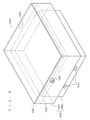
- Schematic diagrams in Fig. 3 and Fig. 4 show a module battery.
- Fig. 3 is a perspective view.
- Fig. 4 is a sectional view.
- a block diagram in Fig. 5 shows a controller, and the like.
- the power storage apparatus stores power in a sodium-sulfur battery (NaS battery).
- the power storage apparatus is preferably connected to an electric power system, and used for the adjustment of power supply/demand, prevention of power failure, and the like.
- a power storage apparatus 1000 includes module batteries 1020, bus bars 1021 outside the module batteries, an intake pipe 1022, an exhaust pipe 1023, a blower 1024, an external temperature sensor 1025, an accessory 1026, a controller 1027, a battery stand 1028, and a sealed container 1029.
- the sealed container 1029 includes an outer wall 1160, and a partition wall 1161.
- the bus bars 1021 outside the module batteries each include a wire 1180 that is arranged between the batteries and a wire 1181 that is not arranged between the batteries.
- each module battery 1020 includes electric cells 1040 of a NaS battery, bus bars 1041 inside the module battery, a heater 1042, sand 1043, module battery terminals 1044, an internal temperature sensor 1045, a heat-insulating container 1046, and a heat insulator 1047.
- the heat-insulating container 1046 includes a box body 1060 and a lid body 1061.
- the box body 1060 includes an outer wall 1080.
- the outer wall 1080 of the box body 1060 includes a bottom wall 1100, and side walls 1101.
- the lid body 1061 includes an outer wall 1120 and a heat transfer wall 1121.
- the outer wall 1120 of the lid body 1061 includes a top wall 1140 and side walls 1141.
- the controller 1027 includes a charging/discharging control unit 1200, a heater control unit 1201, a determination unit 1202, a generation control unit 1203, and a flow rate control unit 1204.
- a component other than these components may be added to the power storage apparatus 1000. A part of these components may be omitted from the power storage apparatus 1000.
- the number of the module batteries 1020 may be increased or decreased, and the number of the module batteries 1020 may be one.
- the number of the electric cells 1040 may be increased or decreased, and the number of the electric cells 1040 maybe one.
- a battery chamber 1220 and an accessory chamber 1221 are formed inside the sealed container 1029.
- a chamber other than the battery chamber 1220 and the accessory chamber 1221 may be formed inside the sealed container 1029.
- the two or more battery chambers 1220 may be formed inside the sealed container 1029.
- the two or more accessory chamber 1221 may be formed inside the sealed container 1029.
- the battery chamber 1220 and the accessory chamber 1221 may be divided by the partition wall 1161.
- the partition wall 1161 hinders the circulation of air between the battery chamber 1220 and the accessory chamber 1221, and suppresses heat transfer from the battery chamber 1220 to the accessory chamber 1221. Consequently, even in a case where the temperature of the battery chamber 1220 rises, the temperature of the accessory chamber 1221 does not easily rise, and the temperature of the accessory chamber 1221 is appropriately maintained.
- the partition wall 1161 may have a heat insulated structure such as a vacuum heat insulated structure.
- an electric cell chamber 1240 and an air chamber 1241 are formed inside the heat-insulating container 1046.
- a chamber other than the electric cell chamber 1240 and the air chamber 1241 may be formed inside the heat-insulating container 1046.
- the two or more electric cell chambers 1240 may be formed inside the heat-insulating container 1046.
- the two or more air chambers 1241 may be formed inside the heat-insulating container 1046.
- the electric cell chamber 1240 and the air chamber 1241 are divided by the heat transfer wall 1121.
- the heat transfer wall 1121 hinders the circulation of air between the electric cell chamber 1240 and the air chamber 1241, but transfers heat from the electric cell chamber 1240 to the air chamber 1241 well. Consequently, the entering of outside air into the electric cell chamber 1240 is suppressed, while heat is exhausted from the electric cell chamber 1240 to the air chamber 1241.
- the heat exhausted to the air chamber 1241 is exhausted outside the sealed container 1029 by the air flow FL.
- the heat transfer wall 1121 may be a flat plate, or fins may be formed on both sides or one side of the principal surface of the heat transfer wall 1121. In a case where the air flow FL is not present, the air chamber 1241 serves as a preferable heat insulating layer, and suppresses heat radiation to the outside.
- the electric cell chamber 1240 is preferably formed in the box body 1060, the heat transfer wall 1121 is preferably provided in the lid body 1061, and the air chamber 1241 is preferably formed in the lid body 1061. Consequently, compared to a case where the air chamber 1241 is formed in the box body 1060, a load applied to the air chamber 1241 is reduced, and the strength of the module batteries 1020 is improved. However, also in a case where the heat transfer wall 1121 is provided in the box body 1060, and the air chamber 1241 is formed in the box body 1060, the effect of exhausting heat by the air flow FL is maintained.
- the air chamber 1241 is preferably formed along the top wall 1140 of the lid body 1061.
- the air chamber 1241 is a space provided between the top wall 1140 of the lid body 1061 and the heat transfer wall 1121, and is surrounded by the top wall 1140 of the lid body 1061, parts, closer to the top wall 1140, of the side walls 1141 of the lid body 1061, and the heat transfer wall 1121.
- the air chamber 1241 is formed along other wall, the effect of exhausting heat by the air flow FL is maintained.
- the module batteries 1020, the wires 1180 that are arranged between the batteries, and the battery stand 1028 are housed in the battery chamber 1220.
- the blower 1024, the accessory 1026, and the controller 1027 are housed in the accessory chamber 1221.
- the wires 1181 that are not arranged between the batteries are housed so as to pass through the partition wall 1161 and extend between the battery chamber 1220 and the accessory chamber 1221.
- a principal part of the intake pipe 1022 is housed so as to pass through the partition wall 1161 and extend between the battery chamber 1220 and the accessory chamber 1221.
- a principal part of an exhaust pipe 1023 is housed in the battery chamber 1220.
- components housed inside the sealed container 1029 components whose allowable upper limit temperatures are relatively high, such as the module batteries 1020, are housed in the battery chamber 1220, and components whose allowable upper limit temperatures are relatively low, such as the accessory 1026, are housed in the accessory chamber 1221.
- the examples of the accessory 1026 include, for example, a cable, a terminal stand, a measurement device, and the like.
- the module batteries 1020 are placed on the battery stand 1028.
- the module batteries 1020 may be housed in a structure which is not generally referred to "stand”.
- the module batteries 1020 are separated from each other, and separated from the outer wall 1160 and the partition wall 1161 of the sealed container 1029.
- the external temperature sensor 1025 is arranged outside the sealed container 1029.
- the electric cells 1040, the bus bars 1041 inside the module battery, the heater 1042, the sand 1043, and the internal temperature sensor 1045 are housed in the electric cell chamber 1240.
- the module battery terminals 1044 pass through the outer wall 1080 of the box body 1060 to extend between the electric cell chamber 1240 and the outside of the heat-insulating container 1046.
- the air chamber 1241 is preferably a space where only air flows. At least an electric device is not housed in the air chamber 1241.
- the electric cells 1040 are buried in the sand 1043.
- the electric cells 1040 are separated from each other.
- the heater 1042 is preferably installed along the outer wall 1080 of the box body 1060, and more preferably installed along the bottom wall 1100 of the box body 1060.
- the two or more electric cells 1040 are arranged in a direction parallel to the air chamber 1241. Consequently, the heat of the two or more electric cells 1040 are uniformly radiated, and dispersion in the two or more electric cells 1040 is not easily caused.
- the number of the electric cells 1040 may be one, or the two or more electric cells 1040 may be arranged in a direction different from the direction parallel to the air chamber 1241.
- an intake port 1260 and an exhaust port 1261 are formed on the outer wall 1120 of the lid body 1061.
- the intake port 1260 and the exhaust port 1261 are connected to the air chamber 1241.
- the intake port 1260 and the exhaust port 1261 are formed on the outer wall 1080 of the box body 1060.
- the intake pipe 1022 is formed with an intake path 1280.
- the exhaust pipe 1023 is formed with an exhaust path 1281.
- the intake pipe 1022 and the exhaust pipe 1023 each may be replaced with a structure which is generally referred to as "pipe".
- the intake pipe 1022 may be replaced with a structure in which the intake path 1280 is formed in a solid body.
- the exhaust pipe 1023 may be replaced with a structure in which the exhaust path 1281 is formed in a solid body.
- One end of the intake path 1280 is connected to the intake port 1260, and the other end of the intake path 1280 is exposed outside the sealed container 1029.
- the intake path 1280 starts from the outside of the sealed container 1029 and leads to the air chamber 1241.
- One end of the exhaust path 1281 is connected to the exhaust port 1261, and the other end of the exhaust path 1281 is exposed outside the sealed container 1029.
- the exhaust path 1281 starts from the air chamber 1241 and leads to the outside of the sealed container 1029.
- the blower 1024 generates the air flow FL which sequentially flows through the intake path 1280, the air chamber 1241, and the exhaust path 1281. Consequently, heat is exhausted from the air chamber 1241 to the outside of the sealed container 1029 by the air flow FL, and the electric cell chamber 1240 is cooled. Additionally, heat transfer from the inside of the heat-insulating container 1046 to the battery chamber 1220 is suppressed, the temperature of the battery chamber 1220 does not easily rise, and the temperature of the battery chamber 1220 is appropriately maintained. Furthermore, outside air does not easily enter a space other than the intake path 1280, the air chamber 1241, and the exhaust path 1281, and the influence of the outside air such as salt damage is suppressed. For example, the battery chamber 1220 is not easily corroded by the salt damage, or an insulation property in the battery chamber 1220 is not easily lowered.
- the blower 1024 may be replaced with other type of air blower.
- the blower 1024 may be replaced with a fan.
- the blower 1024 is inserted into the intake path 1280. Consequently, the blower 1024 is not easily affected by heat. However, in place of the insertion of an air supplying mechanism such as the blower 1024 into the intake path 1280, an air absorbing mechanism such as a pump may be inserted into the exhaust path 1281.
- the exhaust path 1281 starts from the exhaust port 1261 and leads to the outside of the sealed container 1029 without passing through the accessory chamber 1221. Consequently, heat transfer from the exhaust path 1281 to the accessory chamber 1221 is suppressed. The temperature of the accessory chamber 1221 does not easily rise, and the temperature of the accessory chamber 1221 is appropriately maintained.
- the timing of generating the air flow FL may not be independent for each of the module batteries 1020, and the single blower 1024 that is common in the two or more module batteries 1020 is simply prepared. However, a single blower 1024 may be prepared for each of the two or more module batteries 1020, and the timing of generating the air flow FL may be dependent for each of the module batteries 1020.
- the heat-insulating container 1046 has a structure in which an opening of the box body 1060 is covered with the lid body 1061, and the electric cell chamber 1240 is closed by the heat transfer wall 1121. According to this structure, the electric cells 1040 and the like are easily housed in the electric cell chamber 1240, and heat is easily transferred from the electric cell chamber 1240 to the air chamber 1241.
- the heat-insulating container 1046 may have other structure.
- the heat-insulating container 1046 may have a structure in which the container is not separated into the box body 1060 and the lid body 1061.
- the side walls 1141 of the lid body 1061, and the outer wall 1080 of the box body 1060 each have a vacuum heat insulated structure. Consequently, heat transfer from the inside of the heat-insulating container 1046 to the battery chamber 1220 is suppressed, and the rising of the temperature of the battery chamber 1220 is suppressed, and the temperature of the battery chamber 1220 is appropriately maintained.
- the side walls 1141 of the lid body 1061, and the outer wall 1080 of the box body 1060 each may have a heat insulated structure other than the vacuum heat insulated structure.
- heat insulators may be buried in the side walls 1141 of the lid body 1061, and the outer wall 1080 of the box body 1060.
- the top wall 1140 of the lid body 1061 does not have the vacuum heat insulated structure. However, the top wall 1140 of the lid body 1061 may have the vacuum heat insulated structure.
- the heat insulator 1047 is mounted on the top wall 1140 of the lid body 1061.
- the heat insulator 1047 may be mounted on a part other than the top wall 1140 of the lid body 1061.
- the heat insulator 1047 may be mounted on the side walls 1141 of the lid body 1061.
- the heat insulator 1047 faces the air chamber 1241 with the top wall 1140 of the lid body 1061 interposed therebetween. Consequently, heat transfer from the air chamber 1241 to the battery chamber 1220 is suppressed, and the temperature of the battery chamber 1220 does not easily rise, and the temperature of the battery chamber 1220 is appropriately maintained.
- the heat insulator 1047 is omitted, the effect of exhausting heat by the air flow FL is maintained.
- the controller 1027 is a computer in which a control program is installed.
- the controller 1027 executes the control program to control the component of the power storage apparatus 1000.
- One computer may serve as the function of the controller 1027, or two or more computers may serve as the function of the controller 1027.
- Hardware which does not include a control program may serve as a part of or all of the function of the controller 1027.
- the hardware is, for example, an electronic circuit that includes an operational amplifier, a comparator, and the like.
- the cooling control by the controller 1027 may be independent or may not be independent for each of the two or more module batteries 1020. A part of or all of the control by the controller 1027 may be replaced with the operation of an operator.
- the charging/discharging control unit 1200 controls charging to the module batteries 1020 and discharging from the module batteries 1020.
- the heater control unit 1201 controls the heater 1042.
- the determination unit 1202 determines whether or not the cooling of the electric cell chamber 1240 is required.
- the determination unit 1202 determines that the cooling of the electric cell chamber 1240 is required.
- the determination unit 1202 determines that the rising of the temperature of the electric cell chamber 1240 is a reference or more.
- the rising speed of the temperature of the electric cell chamber 1240 may be considered.
- the temperature of the electric cell chamber 1240 is likely to rise, in a case where discharging from the module batteries 1020 is performed. Regardless of the fact whether charging/discharging is performed or not, the determination unit 1202 may determine that the cooling of the electric cell chamber 1240 is required, in a case where the rising of the temperature of the electric cell chamber 1240 is the reference or more.
- the determination unit 1202 determines that the cooling of the electric cell chamber 1240 is not required,.
- the generation control unit 1203 controls the blower 1024 on the basis of a determination result by the determination unit 1202. In a case where the cooling is required, the generation control unit 1203 operates the blower 1024 and generates the air flow FL. In a case where the cooling is not required, the generation control unit 1203 does not operate the blower 1024 and does not generate the air flow FL. In a case where the air flow FL is generated, heat is exhausted from the electric cell chamber 1240 to the outside of the sealed container 1029 by the air flow FL, and the electric cell chamber 1240 is cooled. In a case where the air flow FL is not generated, heat is not easily exhausted from the electric cell chamber 1240, and the thermal insulation property of the heat-insulating container 1046 is improved.
- the electric cell chamber 1240 is cooled.
- the thermal insulation property of the heat-insulating container 1046 is improved, and the temperature of the electric cell chamber 1240 is appropriately maintained.
- the heater 1042 is operated, the electric cell chamber 1240 is not cooled, the power consumption of the heater 1042 is thus reduced, and the power loss of the power storage apparatus 1000 is reduced.
- the flow rate control unit 1204 controls the blower 1024 such that the flow rate of the air flow FL is increased as the temperature of outside air measured by the external temperature sensor 1025 rises. Consequently, even in a case where the temperature of the outside air is high, the exhaust capacity of heat from the electric cell chamber 1240 to the outside of the sealed container 1029 is maintained, and the temperature of the electric cell chamber 1240 is appropriately maintained. However, also in a case where the flow rate of the air flow FL is constant, the effect of exhausting heat by the air flow FL is maintained.
- the intermittent operation of the blower 1024 may be performed, and the ratio of time during which the blower 1024 is operated may be increased as the temperature of the outside air rises.
- the bus bars 1021 outside the module batteries serve as the charging/discharging paths of the module batteries 1020 inside the sealed container 1029.
- the bus bars 1041 inside the module batteries serve as the charging/discharging paths of the electric cells 1040 inside the module batteries 1020.
- the bus bars 1021 and 1041 are electrically connected to each other via the module battery terminals 1044.
- the module battery terminals 1044 may be omitted, and the bus bars 1021 and 1041 may be directly connected to each other.
- the bus bars 1021 and 1041 are each configured from a conductor such as copper and aluminum.
- the bus bars 1021 and 1041 each are a bar-shaped body having a rectangular sectional shape.
- the bus bars 1021 and 1041 each are a bare wire line that is not coated by insulated coating. In a case where the bus bars 1021 and 1041 are not coated by the insulated coating, the heat resisting properties of the bus bars 1021 and 1041 are improved, but the bus bars 1021 and 1041 are easily affected by outside air such as salt damage.
- outside air does not easily enter the battery chamber 1220 and the accessory chamber 1221 that house the bus bars 1021 outside the module batteries therein, and outside air does not easily enter the electric cell chambers 1240 that house the bus bars 1041 inside the module batteries. Therefore, a large problem does not occur also in a case where the bus bars 1021 and 1041 are easily affected by outside air such as salt damage. Additionally, the temperature of the battery chamber 1220 can be reduced to an allowable temperature of the insulated coating or less by using this cooling method, and therefore the bus bars 1021 and 1041 may be coated by the insulated coating, or may be replaced with other type of wiring materials.
- the sealed container 1029 is a sealed container that has a sealing property enough to hinder the entering of outside air which affects an object housed inside the sealed container 1029.
- a sealing property with a degree required to a vacuum container is not required to the sealed container 1029.
Landscapes
- Chemical & Material Sciences (AREA)
- Chemical Kinetics & Catalysis (AREA)
- Electrochemistry (AREA)
- General Chemical & Material Sciences (AREA)
- Engineering & Computer Science (AREA)
- Manufacturing & Machinery (AREA)
- Secondary Cells (AREA)
Abstract
Description
- The present invention relates to a power storage apparatus and a method of operating a power storage apparatus.
- A sodium-sulfur battery (NaS battery) operates at a high temperature. Therefore, in the NaS battery, electric cells, a heater, and the like are housed inside a container (heat-insulating container), and the temperature of the inside of the container is maintained at a high temperature, as shown in Patent Document 1. However, as mentioned in Paragraph 0010 of Patent Document 1, it is not preferable that the temperature of the inside of the container excessively rises, and therefore heat is exhausted from the inside of the container to the outside as necessary.
- On the other hand, in a power storage apparatus (power storage compensation apparatus) provided with a NaS battery, a battery (module battery) in which electric cells are housed inside a container is sometimes further housed in an unsealed container (package), as shown in Patent Document 2. Heat exhausted from the inside of the container to the outside is exhausted from the inside of the unsealed container to the outside by an air flow that passes inside the unsealed container.
- As mentioned in Paragraph 0037 of Patent Document 2, in a case where the power storage apparatus is installed in an area where salt damage may occur, a salt-resistant filter is installed on an intake port of the unsealed container in order to prevent salt damage.
-
- Patent Document 1: Japanese Patent Application Laid-Open No.
2004-47208 - Patent Document 2: Japanese Patent Application Laid-Open No.
2008-226488 - However, in the invention of Patent Document 2, a cost for replacing the salt-resistant filter is increased. In a case where a battery is housed in a sealed container, the salt-resistant filter is not required, but an air conditioner that cools the inside of the sealed container is required in order to maintain the temperature of the inside of the sealed container at an appropriate temperature, and an operating cost and a maintenance cost of the air conditioner are increased. Particularly, in a case where the temperature of the outside air is high, necessary power is increased such that the temperature of an object housed inside the sealed container is not made higher than an allowable upper limit temperature.
- The present invention is conceived in order to solve these problems. An object of the present invention is to provide a power storage apparatus, in which an operation cost and a maintenance cost are not increased, and the temperature of the inside is appropriately maintained, the power storage apparatus being not easily affected by outside air such as salt damage.
- The present invention is directed to a power storage apparatus.
- In a first aspect of the present invention, a battery, a charging/discharging path outside a battery, a sealed container, an intake path formation, an exhaust path formation, a generation mechanism, a determination unit, and a generation control unit are provided in a power storage apparatus.
- The battery includes a container, an electric cell of a sodium-sulfur battery, and a charging/discharging path inside a battery.
- The container includes an outer wall and a heat transfer wall. An electric cell chamber and an air chamber are formed inside the container. The heat transfer wall divides the electric cell chamber and the air chamber. The electric cell and the charging/discharging path inside a battery are housed in the electric cell chamber.
- The charging/discharging path outside a battery, and the charging/discharging path inside a battery are electrically connected to each other.
- The sealed container houses the battery, and the charging/discharging path outside a battery.
- An intake path formed in the intake path formation starts from outside of the sealed container and leads to the air chamber.
- An exhaust path formed in the exhaust path formation starts from the air chamber and leads to outside of the sealed container.
- The generation mechanism generates an air flow which sequentially flows through the intake path, the air chamber, and the exhaust path.
- The determination unit determines whether or not cooling of the electric cell chamber is required.
- The generation control unit controls the generation mechanism such that the air flow is generated in a case where the cooling of the electric cell chamber is required, and the air flow is not generated in a case where the cooling of the electric cell chamber is not required
- A second aspect of the present invention further adds a matter to the first aspect of the present invention.
- In the second aspect of the present invention, a first temperature sensor is provided in the battery. The first temperature sensor is housed in the electric cell chamber. The determination unit determines that the cooling of the electric cell chamber is required, in a case where rising of a temperature measured by the first temperature sensor is a reference or more.
- A third aspect of the present invention further adds a matter to the second aspect of the present invention.
- In the third aspect of the present invention, a second temperature sensor and a flow rate control unit are provided in the power storage apparatus.
- The second temperature sensor is arranged outside the sealed container.
- The flow rate control unit controls the generation mechanism such that a flow rate of the air flow is increased as a temperature measured by the second temperature sensor rises.
- A fourth aspect of the present invention further adds a matter to any of the first to third aspects of the present invention. In the fourth aspect of the present invention, a heat insulator is further provided in the battery.
- The heat insulator and the air chamber face with each other with an outer wall interposed therebetween.
- A fifth aspect of the present invention further adds a matter to any of the first to fourth aspects of the present invention. In the fifth aspect of the present invention, an accessory is provided in the power storage apparatus.
- A battery chamber and an accessory chamber are formed inside the sealed container. The battery is housed in the battery chamber. The accessory is housed in the accessory chamber.
- The sealed container includes a partition wall. The partition wall divides the battery chamber and the accessory chamber.
- The sixth aspect of the present invention further adds a matter to the fifth aspect of the present invention. In the sixth aspect of the present invention, the exhaust path does not pass through the accessory chamber.
- The seventh aspect of the present invention further adds a matter to any of the first to sixth aspects of the present invention. In the seventh aspect of the present invention, the two or more electric cells are arranged in a direction parallel to the air chamber.
- The present invention is also directed to a method of operating a power storage apparatus.
- According to the first aspect of the present invention, an operation cost and a maintenance cost are not increased.
- In a case where the cooling of the electric cell chamber is required, heat is exhausted from the electric cell chamber to the outside of the sealed container by the air flow. In a case where the cooling of the electric cell chamber is not required, the thermal insulation property of the container is improved. The temperature of the electric cell chamber is appropriately maintained.
- Exhaust from the electric cell chamber to the battery chamber is suppressed. The temperature of the battery chamber is appropriately maintained.
- Outside air does not easily enter a space other than the intake path, the air chamber, and the exhaust path. The influence of the outside air is suppressed.
- According to the second aspect of the present invention, heat is exhausted from the electric cell chamber to the outside of the sealed container in a case where the temperature of the electric cell chamber rises. The temperature of the electric cell chamber is appropriately maintained.
- According to the third aspect of the present invention, even in a case where the temperature of outside air is high, the exhaust capacity of heat from the electric cell chamber to the outside of the sealed container is maintained. The temperature of the electric cell chamber is appropriately maintained.
- According to the fourth aspect of the present invention, heat transfer from the electric cell chamber to the inside of the sealed container is suppressed. The temperature of the inside of the sealed chamber is appropriately maintained.
- According to the fifth aspect of the present invention, heat transfer from the battery chamber to the accessory chamber is suppressed. The temperature of the accessory chamber is appropriately maintained.
- According to the sixth aspect of the present invention, heat transfer from the exhaust path to the accessory chamber is suppressed. The temperature of the accessory chamber is appropriately maintained.
- According to the seventh aspect of the present invention, the heat of the two or more electric cells are uniformly radiated, and dispersion in the two or more electric cells is not easily caused.
- These and other objects, features, aspects and advantages of the present invention will become more apparent from the following detailed description of the present invention when taken in conjunction with the accompanying drawings.
-
-
Fig. 1 is a front view of a power storage apparatus. -
Fig. 2 is a rear view of power storage apparatus. -
Fig. 3 is a perspective view of a battery module. -
Fig. 4 is a sectional view of the battery module. -
Fig. 5 is a block diagram of a controller. - Schematic diagrams in
Fig. 1 andFig. 2 show a preferred embodiment of a power storage apparatus.Fig. 1 is a front view.Fig. 2 is a rear view. Schematic diagrams inFig. 3 andFig. 4 show a module battery.Fig. 3 is a perspective view.Fig. 4 is a sectional view. A block diagram inFig. 5 shows a controller, and the like. The power storage apparatus stores power in a sodium-sulfur battery (NaS battery). The power storage apparatus is preferably connected to an electric power system, and used for the adjustment of power supply/demand, prevention of power failure, and the like. - As shown in
Fig. 1 andFig. 2 , apower storage apparatus 1000 includesmodule batteries 1020,bus bars 1021 outside the module batteries, anintake pipe 1022, anexhaust pipe 1023, ablower 1024, anexternal temperature sensor 1025, anaccessory 1026, acontroller 1027, abattery stand 1028, and a sealedcontainer 1029. - The sealed
container 1029 includes anouter wall 1160, and apartition wall 1161. - The bus bars 1021 outside the module batteries each include a
wire 1180 that is arranged between the batteries and awire 1181 that is not arranged between the batteries. - As shown in
Fig. 3 andFig. 4 , eachmodule battery 1020 includeselectric cells 1040 of a NaS battery,bus bars 1041 inside the module battery, aheater 1042,sand 1043,module battery terminals 1044, aninternal temperature sensor 1045, a heat-insulatingcontainer 1046, and aheat insulator 1047. - The heat-insulating
container 1046 includes abox body 1060 and alid body 1061. - The
box body 1060 includes anouter wall 1080. Theouter wall 1080 of thebox body 1060 includes abottom wall 1100, andside walls 1101. - The
lid body 1061 includes anouter wall 1120 and aheat transfer wall 1121. Theouter wall 1120 of thelid body 1061 includes atop wall 1140 andside walls 1141. - As shown in
Fig. 5 , thecontroller 1027 includes a charging/dischargingcontrol unit 1200, aheater control unit 1201, adetermination unit 1202, ageneration control unit 1203, and a flowrate control unit 1204. - A component other than these components may be added to the
power storage apparatus 1000. A part of these components may be omitted from thepower storage apparatus 1000. The number of themodule batteries 1020 may be increased or decreased, and the number of themodule batteries 1020 may be one. The number of theelectric cells 1040 may be increased or decreased, and the number of theelectric cells 1040 maybe one. - As shown in
Fig. 1 andFig. 2 , abattery chamber 1220 and anaccessory chamber 1221 are formed inside the sealedcontainer 1029. A chamber other than thebattery chamber 1220 and theaccessory chamber 1221 may be formed inside the sealedcontainer 1029. The two ormore battery chambers 1220 may be formed inside the sealedcontainer 1029. The two ormore accessory chamber 1221 may be formed inside the sealedcontainer 1029. - The
battery chamber 1220 and theaccessory chamber 1221 may be divided by thepartition wall 1161. Thepartition wall 1161 hinders the circulation of air between thebattery chamber 1220 and theaccessory chamber 1221, and suppresses heat transfer from thebattery chamber 1220 to theaccessory chamber 1221. Consequently, even in a case where the temperature of thebattery chamber 1220 rises, the temperature of theaccessory chamber 1221 does not easily rise, and the temperature of theaccessory chamber 1221 is appropriately maintained. However, also in a case where thepartition wall 1161 is omitted, and theaccessory chamber 1221 partitioned from thebattery chamber 1220 is not formed, the effect of exhausting heat by an air flow FL described later is maintained. Thepartition wall 1161 may have a heat insulated structure such as a vacuum heat insulated structure. - As shown in
Fig. 3 andFig. 4 , anelectric cell chamber 1240 and anair chamber 1241 are formed inside the heat-insulatingcontainer 1046. A chamber other than theelectric cell chamber 1240 and theair chamber 1241 may be formed inside the heat-insulatingcontainer 1046. The two or moreelectric cell chambers 1240 may be formed inside the heat-insulatingcontainer 1046. The two ormore air chambers 1241 may be formed inside the heat-insulatingcontainer 1046. - The
electric cell chamber 1240 and theair chamber 1241 are divided by theheat transfer wall 1121. Theheat transfer wall 1121 hinders the circulation of air between theelectric cell chamber 1240 and theair chamber 1241, but transfers heat from theelectric cell chamber 1240 to theair chamber 1241 well. Consequently, the entering of outside air into theelectric cell chamber 1240 is suppressed, while heat is exhausted from theelectric cell chamber 1240 to theair chamber 1241. The heat exhausted to theair chamber 1241 is exhausted outside the sealedcontainer 1029 by the air flow FL. Theheat transfer wall 1121 may be a flat plate, or fins may be formed on both sides or one side of the principal surface of theheat transfer wall 1121. In a case where the air flow FL is not present, theair chamber 1241 serves as a preferable heat insulating layer, and suppresses heat radiation to the outside. - The
electric cell chamber 1240 is preferably formed in thebox body 1060, theheat transfer wall 1121 is preferably provided in thelid body 1061, and theair chamber 1241 is preferably formed in thelid body 1061. Consequently, compared to a case where theair chamber 1241 is formed in thebox body 1060, a load applied to theair chamber 1241 is reduced, and the strength of themodule batteries 1020 is improved. However, also in a case where theheat transfer wall 1121 is provided in thebox body 1060, and theair chamber 1241 is formed in thebox body 1060, the effect of exhausting heat by the air flow FL is maintained. - The
air chamber 1241 is preferably formed along thetop wall 1140 of thelid body 1061. Theair chamber 1241 is a space provided between thetop wall 1140 of thelid body 1061 and theheat transfer wall 1121, and is surrounded by thetop wall 1140 of thelid body 1061, parts, closer to thetop wall 1140, of theside walls 1141 of thelid body 1061, and theheat transfer wall 1121. However, also in a case where theair chamber 1241 is formed along other wall, the effect of exhausting heat by the air flow FL is maintained. - As shown in
Fig. 1 andFig. 2 , themodule batteries 1020, thewires 1180 that are arranged between the batteries, and thebattery stand 1028 are housed in thebattery chamber 1220. Theblower 1024, theaccessory 1026, and thecontroller 1027 are housed in theaccessory chamber 1221. Thewires 1181 that are not arranged between the batteries are housed so as to pass through thepartition wall 1161 and extend between thebattery chamber 1220 and theaccessory chamber 1221. A principal part of theintake pipe 1022 is housed so as to pass through thepartition wall 1161 and extend between thebattery chamber 1220 and theaccessory chamber 1221. A principal part of anexhaust pipe 1023 is housed in thebattery chamber 1220. - Among the components housed inside the sealed
container 1029, components whose allowable upper limit temperatures are relatively high, such as themodule batteries 1020, are housed in thebattery chamber 1220, and components whose allowable upper limit temperatures are relatively low, such as theaccessory 1026, are housed in theaccessory chamber 1221. The examples of theaccessory 1026 include, for example, a cable, a terminal stand, a measurement device, and the like. - The
module batteries 1020 are placed on thebattery stand 1028. Themodule batteries 1020 may be housed in a structure which is not generally referred to "stand". Themodule batteries 1020 are separated from each other, and separated from theouter wall 1160 and thepartition wall 1161 of the sealedcontainer 1029. - The
external temperature sensor 1025 is arranged outside the sealedcontainer 1029. - As shown in
Fig. 3 andFig. 4 , theelectric cells 1040, thebus bars 1041 inside the module battery, theheater 1042, thesand 1043, and theinternal temperature sensor 1045 are housed in theelectric cell chamber 1240. Themodule battery terminals 1044 pass through theouter wall 1080 of thebox body 1060 to extend between theelectric cell chamber 1240 and the outside of the heat-insulatingcontainer 1046. Theair chamber 1241 is preferably a space where only air flows. At least an electric device is not housed in theair chamber 1241. - The
electric cells 1040 are buried in thesand 1043. Theelectric cells 1040 are separated from each other. - The
heater 1042 is preferably installed along theouter wall 1080 of thebox body 1060, and more preferably installed along thebottom wall 1100 of thebox body 1060. - As shown in
Fig. 3 andFig. 4 , the two or moreelectric cells 1040 are arranged in a direction parallel to theair chamber 1241. Consequently, the heat of the two or moreelectric cells 1040 are uniformly radiated, and dispersion in the two or moreelectric cells 1040 is not easily caused. However, the number of theelectric cells 1040 may be one, or the two or moreelectric cells 1040 may be arranged in a direction different from the direction parallel to theair chamber 1241. - As shown in
Fig. 3 andFig. 4 , anintake port 1260 and anexhaust port 1261 are formed on theouter wall 1120 of thelid body 1061. Theintake port 1260 and theexhaust port 1261 are connected to theair chamber 1241. In a case where theair chamber 1241 is formed in thebox body 1060, theintake port 1260 and theexhaust port 1261 are formed on theouter wall 1080 of thebox body 1060. - As shown in
Fig. 1 andFig. 2 , theintake pipe 1022 is formed with anintake path 1280. Theexhaust pipe 1023 is formed with anexhaust path 1281. Theintake pipe 1022 and theexhaust pipe 1023 each may be replaced with a structure which is generally referred to as "pipe". For example, theintake pipe 1022 may be replaced with a structure in which theintake path 1280 is formed in a solid body. Theexhaust pipe 1023 may be replaced with a structure in which theexhaust path 1281 is formed in a solid body. - One end of the
intake path 1280 is connected to theintake port 1260, and the other end of theintake path 1280 is exposed outside the sealedcontainer 1029. Theintake path 1280 starts from the outside of the sealedcontainer 1029 and leads to theair chamber 1241. One end of theexhaust path 1281 is connected to theexhaust port 1261, and the other end of theexhaust path 1281 is exposed outside the sealedcontainer 1029. Theexhaust path 1281 starts from theair chamber 1241 and leads to the outside of the sealedcontainer 1029. Consequently, a path of the air flow FL that starts from the outside of the sealedcontainer 1029 and leads to the outside of the sealedcontainer 1029 via theair chamber 1241 is formed, so that air outside the sealed container 1029 (hereinafter referred to as "outside air") can flow in theair chamber 1241. - The
blower 1024 generates the air flow FL which sequentially flows through theintake path 1280, theair chamber 1241, and theexhaust path 1281. Consequently, heat is exhausted from theair chamber 1241 to the outside of the sealedcontainer 1029 by the air flow FL, and theelectric cell chamber 1240 is cooled. Additionally, heat transfer from the inside of the heat-insulatingcontainer 1046 to thebattery chamber 1220 is suppressed, the temperature of thebattery chamber 1220 does not easily rise, and the temperature of thebattery chamber 1220 is appropriately maintained. Furthermore, outside air does not easily enter a space other than theintake path 1280, theair chamber 1241, and theexhaust path 1281, and the influence of the outside air such as salt damage is suppressed. For example, thebattery chamber 1220 is not easily corroded by the salt damage, or an insulation property in thebattery chamber 1220 is not easily lowered. - The
blower 1024 may be replaced with other type of air blower. For example, theblower 1024 may be replaced with a fan. - The
blower 1024 is inserted into theintake path 1280. Consequently, theblower 1024 is not easily affected by heat. However, in place of the insertion of an air supplying mechanism such as theblower 1024 into theintake path 1280, an air absorbing mechanism such as a pump may be inserted into theexhaust path 1281. - The
exhaust path 1281 starts from theexhaust port 1261 and leads to the outside of the sealedcontainer 1029 without passing through theaccessory chamber 1221. Consequently, heat transfer from theexhaust path 1281 to theaccessory chamber 1221 is suppressed. The temperature of theaccessory chamber 1221 does not easily rise, and the temperature of theaccessory chamber 1221 is appropriately maintained. - In a case where the two or
more module batteries 1020 are charged/discharged in synchronization, in all of the two ormore module batteries 1020, the temperatures of theelectric cell chambers 1240 are the same level. Therefore, the timing of generating the air flow FL may not be independent for each of themodule batteries 1020, and thesingle blower 1024 that is common in the two ormore module batteries 1020 is simply prepared. However, asingle blower 1024 may be prepared for each of the two ormore module batteries 1020, and the timing of generating the air flow FL may be dependent for each of themodule batteries 1020. - As shown in
Fig. 3 andFig. 4 , the heat-insulatingcontainer 1046 has a structure in which an opening of thebox body 1060 is covered with thelid body 1061, and theelectric cell chamber 1240 is closed by theheat transfer wall 1121. According to this structure, theelectric cells 1040 and the like are easily housed in theelectric cell chamber 1240, and heat is easily transferred from theelectric cell chamber 1240 to theair chamber 1241. However, the heat-insulatingcontainer 1046 may have other structure. The heat-insulatingcontainer 1046 may have a structure in which the container is not separated into thebox body 1060 and thelid body 1061. - The
side walls 1141 of thelid body 1061, and theouter wall 1080 of thebox body 1060 each have a vacuum heat insulated structure. Consequently, heat transfer from the inside of the heat-insulatingcontainer 1046 to thebattery chamber 1220 is suppressed, and the rising of the temperature of thebattery chamber 1220 is suppressed, and the temperature of thebattery chamber 1220 is appropriately maintained. Theside walls 1141 of thelid body 1061, and theouter wall 1080 of thebox body 1060 each may have a heat insulated structure other than the vacuum heat insulated structure. For example, heat insulators may be buried in theside walls 1141 of thelid body 1061, and theouter wall 1080 of thebox body 1060. Thetop wall 1140 of thelid body 1061 does not have the vacuum heat insulated structure. However, thetop wall 1140 of thelid body 1061 may have the vacuum heat insulated structure. - As shown in
Fig. 3 andFig. 4 , theheat insulator 1047 is mounted on thetop wall 1140 of thelid body 1061. Theheat insulator 1047 may be mounted on a part other than thetop wall 1140 of thelid body 1061. For example, theheat insulator 1047 may be mounted on theside walls 1141 of thelid body 1061. Theheat insulator 1047 faces theair chamber 1241 with thetop wall 1140 of thelid body 1061 interposed therebetween. Consequently, heat transfer from theair chamber 1241 to thebattery chamber 1220 is suppressed, and the temperature of thebattery chamber 1220 does not easily rise, and the temperature of thebattery chamber 1220 is appropriately maintained. However, also in a case where theheat insulator 1047 is omitted, the effect of exhausting heat by the air flow FL is maintained. - The
controller 1027 is a computer in which a control program is installed. Thecontroller 1027 executes the control program to control the component of thepower storage apparatus 1000. One computer may serve as the function of thecontroller 1027, or two or more computers may serve as the function of thecontroller 1027. Hardware which does not include a control program may serve as a part of or all of the function of thecontroller 1027. The hardware is, for example, an electronic circuit that includes an operational amplifier, a comparator, and the like. The cooling control by thecontroller 1027 may be independent or may not be independent for each of the two ormore module batteries 1020. A part of or all of the control by thecontroller 1027 may be replaced with the operation of an operator. - The charging/discharging
control unit 1200 controls charging to themodule batteries 1020 and discharging from themodule batteries 1020. Theheater control unit 1201 controls theheater 1042. - The
determination unit 1202 determines whether or not the cooling of theelectric cell chamber 1240 is required. - For example, in a case where the charging/discharging
control unit 1200 performs charging/discharging, and the rising of the temperature of eachelectric cell chamber 1240, which is measured by theinternal temperature sensor 1045, is a reference or more, thedetermination unit 1202 determines that the cooling of theelectric cell chamber 1240 is required. Typically, in a case where the temperature of theelectric cell chamber 1240 reaches a reference value (threshold value) or more, thedetermination unit 1202 determines that the rising of the temperature of theelectric cell chamber 1240 is a reference or more. However, other factors such as the rising speed of the temperature of theelectric cell chamber 1240, a charging/discharging current, and charging/discharging power may be considered. The temperature of theelectric cell chamber 1240 is likely to rise, in a case where discharging from themodule batteries 1020 is performed. Regardless of the fact whether charging/discharging is performed or not, thedetermination unit 1202 may determine that the cooling of theelectric cell chamber 1240 is required, in a case where the rising of the temperature of theelectric cell chamber 1240 is the reference or more. - For example, in a case where the
heater control unit 1201 operates theheater 1042, thedetermination unit 1202 determines that the cooling of theelectric cell chamber 1240 is not required,. - The
generation control unit 1203 controls theblower 1024 on the basis of a determination result by thedetermination unit 1202. In a case where the cooling is required, thegeneration control unit 1203 operates theblower 1024 and generates the air flow FL. In a case where the cooling is not required, thegeneration control unit 1203 does not operate theblower 1024 and does not generate the air flow FL. In a case where the air flow FL is generated, heat is exhausted from theelectric cell chamber 1240 to the outside of the sealedcontainer 1029 by the air flow FL, and theelectric cell chamber 1240 is cooled. In a case where the air flow FL is not generated, heat is not easily exhausted from theelectric cell chamber 1240, and the thermal insulation property of the heat-insulatingcontainer 1046 is improved. - Consequently, in a case where the cooling of the
electric cell chamber 1240 is required, theelectric cell chamber 1240 is cooled. In a case where the cooling of theelectric cell chamber 1240 is not required, the thermal insulation property of the heat-insulatingcontainer 1046 is improved, and the temperature of theelectric cell chamber 1240 is appropriately maintained. In a case where theheater 1042 is operated, theelectric cell chamber 1240 is not cooled, the power consumption of theheater 1042 is thus reduced, and the power loss of thepower storage apparatus 1000 is reduced. - The flow
rate control unit 1204 controls theblower 1024 such that the flow rate of the air flow FL is increased as the temperature of outside air measured by theexternal temperature sensor 1025 rises. Consequently, even in a case where the temperature of the outside air is high, the exhaust capacity of heat from theelectric cell chamber 1240 to the outside of the sealedcontainer 1029 is maintained, and the temperature of theelectric cell chamber 1240 is appropriately maintained. However, also in a case where the flow rate of the air flow FL is constant, the effect of exhausting heat by the air flow FL is maintained. The intermittent operation of theblower 1024 may be performed, and the ratio of time during which theblower 1024 is operated may be increased as the temperature of the outside air rises. - As shown in
Fig. 1 andFig. 2 , thebus bars 1021 outside the module batteries serve as the charging/discharging paths of themodule batteries 1020 inside the sealedcontainer 1029. The bus bars 1041 inside the module batteries serve as the charging/discharging paths of theelectric cells 1040 inside themodule batteries 1020. The bus bars 1021 and 1041 are electrically connected to each other via themodule battery terminals 1044. Themodule battery terminals 1044 may be omitted, and thebus bars - The bus bars 1021 and 1041 are each configured from a conductor such as copper and aluminum. The bus bars 1021 and 1041 each are a bar-shaped body having a rectangular sectional shape. The bus bars 1021 and 1041 each are a bare wire line that is not coated by insulated coating. In a case where the
bus bars bus bars bus bars power storage apparatus 1000, outside air does not easily enter thebattery chamber 1220 and theaccessory chamber 1221 that house thebus bars 1021 outside the module batteries therein, and outside air does not easily enter theelectric cell chambers 1240 that house thebus bars 1041 inside the module batteries. Therefore, a large problem does not occur also in a case where thebus bars battery chamber 1220 can be reduced to an allowable temperature of the insulated coating or less by using this cooling method, and therefore thebus bars - The sealed
container 1029 is a sealed container that has a sealing property enough to hinder the entering of outside air which affects an object housed inside the sealedcontainer 1029. A sealing property with a degree required to a vacuum container is not required to the sealedcontainer 1029. - According to the
power storage apparatus 1000, a maintenance cost for countermeasures against salt damage is not increased. - Although the present invention has been described in detail, the aforementioned description is merely exemplification and not limitation in all aspects. Therefore, it is understood that numberless corrections and modifications can be devised without departing the scope of the present invention.
-
- 1000
- power storage apparatus
- 1020
- module battery
- 1021
- bus bar outside module battery
- 1022
- intake pipe
- 1023
- exhaust pipe
- 1024
- blower
- 1025
- external temperature sensor
- 1026
- accessory
- 1027
- controller
- 1029
- sealed container
- 1040
- electric cell
- 1041
- bus bar inside module battery
- 1045
- internal temperature sensor
- 1046
- heat-insulating container
- 1047
- heat insulator
Claims (8)
- A power storage apparatus comprising:a battery that includes a container, an electric cell of a sodium-sulfur battery, and a charging/discharging path inside the battery, said container including an outer wall and a heat transfer wall, an electric cell chamber and an air chamber being formed inside said container, said heat transfer wall dividing said electric cell chamber and said air chamber, and said electric cell and said charging/discharging path inside the battery being housed in said electric cell chamber;a charging/discharging path outside the battery that is electrically connected to said charging/discharging path inside the battery;a sealed container that houses said battery and said charging/discharging path outside the battery;an intake path formation that is formed with an intake path which starts from outside of said sealed container and leads to said air chamber;an exhaust path formation that is formed with an exhaust path which starts from said air chamber and leads to outside of said sealed container;a generation mechanism that generates an air flow which sequentially flows through said intake path, said air chamber, and said exhaust path;a determination unit that determines whether or not cooling of said electric cell chamber is required; anda generation control unit that controls said generation mechanism such that said air flow is generated in a case where said determination unit determines that the cooling of said electric cell chamber is required, and said air flow is not generated in a case where said determination unit determines that the cooling of said electric cell chamber is not required.
- The power storage apparatus according to claim 1, wherein
said battery further includes a first temperature sensor that is housed in said electric cell chamber, and
said determination unit determines that the cooling of said electric cell chamber is required, in a case where rising of a temperature measured by said first temperature sensor is a reference or more. - The power storage apparatus according to claim 2, further comprising:a second temperature sensor that is arranged outside said sealed container; anda flow rate control unit that controls said generation mechanism such that a flow rate of said air flow is increased as a temperature measured by said second temperature sensor rises.
- The power storage apparatus according to claim 1, further comprising:a heat insulator that faces said air chamber with said outer wall interposed therebetween.
- The power storage apparatus according to claim 1, further comprising:an accessory, whereina battery chamber and an accessory chamber are formed inside said sealed container,said battery is housed in said battery chamber,said accessory is housed in said accessory chamber, andsaid sealed container further includes a partition wall that divides said battery chamber and said accessory chamber.
- The power storage apparatus according to claim 5, wherein
said exhaust path does not pass through said accessory chamber. - The power storage apparatus according to any of claims 1 to 6, wherein
two or more said electric cells are arranged in a direction parallel to said air chamber. - A method of operating a power storage apparatus comprising the steps of:(a) preparing a power storage apparatus including a battery, a charging/discharging path outside the battery, a sealed container, an intake path formation, an exhaust path formation, and a generation mechanism, said battery including a container, an electric cell of a sodium-sulfur battery, and a charging/discharging path inside the battery, said container including an outer wall and a heat transfer wall, an electric cell chamber and an air chamber being formed inside said container, said heat transfer wall dividing said electric cell chamber and said air chamber, and said electric cell and said charging/discharging path inside the battery being housed in said electric cell chamber, said charging/discharging path outside the battery and said charging/discharging path inside the battery being electrically connected to each other; said sealed container housing said battery and said charging/discharging path outside the battery; an intake path which starts from outside of said sealed container and leads to said air chamber being formed in said intake path formation; an exhaust path which starts from said air chamber and leads to outside of said sealed container being formed in said exhaust path formation; and said generation mechanism generating an air flow which sequentially flows through said intake path, said air chamber, and said exhaust path;(b) determining whether or not cooling of said electric cell chamber is required; and(c) controlling said generation mechanism such that said air flow is generated in a case where it is determined that the cooling of said electric cell chamber is required, and said air flow is not generated in a case where it is determined that the cooling of said electric cell chamber is not required.
Applications Claiming Priority (2)
| Application Number | Priority Date | Filing Date | Title |
|---|---|---|---|
| JP2012011800 | 2012-01-24 | ||
| PCT/JP2012/079481 WO2013111426A1 (en) | 2012-01-24 | 2012-11-14 | Power storage apparatus and method of operating power storage apparatus |
Publications (3)
| Publication Number | Publication Date |
|---|---|
| EP2808934A1 true EP2808934A1 (en) | 2014-12-03 |
| EP2808934A4 EP2808934A4 (en) | 2015-10-21 |
| EP2808934B1 EP2808934B1 (en) | 2017-04-12 |
Family
ID=48873168
Family Applications (1)
| Application Number | Title | Priority Date | Filing Date |
|---|---|---|---|
| EP12866796.1A Active EP2808934B1 (en) | 2012-01-24 | 2012-11-14 | Power storage apparatus and method of operating power storage apparatus |
Country Status (5)
| Country | Link |
|---|---|
| US (1) | US9859592B2 (en) |
| EP (1) | EP2808934B1 (en) |
| JP (1) | JP5972912B2 (en) |
| CN (1) | CN104040778B (en) |
| WO (1) | WO2013111426A1 (en) |
Cited By (1)
| Publication number | Priority date | Publication date | Assignee | Title |
|---|---|---|---|---|
| CN107431258A (en) * | 2015-02-23 | 2017-12-01 | 日本碍子株式会社 | Accumulator control device |
Families Citing this family (11)
| Publication number | Priority date | Publication date | Assignee | Title |
|---|---|---|---|---|
| JP5954144B2 (en) * | 2012-11-30 | 2016-07-20 | ソニー株式会社 | Control device, control method, control system, and electric vehicle |
| JP6388866B2 (en) * | 2013-08-26 | 2018-09-12 | 日本碍子株式会社 | Secondary battery equipment |
| CN105659431B (en) * | 2013-10-17 | 2019-05-07 | 日本碍子株式会社 | Secondary battery |
| JP6491663B2 (en) * | 2014-12-30 | 2019-03-27 | エスゼット ディージェイアイ テクノロジー カンパニー リミテッドSz Dji Technology Co.,Ltd | Battery preheating method, apparatus and equipment |
| TWI619426B (en) * | 2016-02-24 | 2018-03-21 | 台達電子工業股份有限公司 | Container energy storage system |
| GB2555083A (en) * | 2016-10-03 | 2018-04-25 | Ge Energy Power Conversion Technology Ltd | Methods of space cooling |
| CN106960928B (en) * | 2017-05-16 | 2023-07-18 | 华霆(合肥)动力技术有限公司 | Battery case and power supply device |
| JP7025246B2 (en) * | 2018-03-08 | 2022-02-24 | 本田技研工業株式会社 | Battery module |
| JP6936923B2 (en) * | 2019-03-14 | 2021-09-22 | 日本碍子株式会社 | Battery container |
| CN113224431A (en) * | 2021-03-18 | 2021-08-06 | 浙江安力能源有限公司 | Energy storage cabinet for sodium salt battery energy storage system |
| CN114156559B (en) * | 2021-09-28 | 2024-02-23 | 国网山东省电力公司潍坊供电公司 | Power supply protection device for cable direction adjustment equipment |
Family Cites Families (20)
| Publication number | Priority date | Publication date | Assignee | Title |
|---|---|---|---|---|
| JPS4912329A (en) * | 1972-05-16 | 1974-02-02 | ||
| US4383013A (en) * | 1980-07-23 | 1983-05-10 | Chloride Silent Power Limited | High temperature multicell electrochemical storage batteries |
| DE3247969C2 (en) * | 1982-12-24 | 1987-04-02 | Brown, Boveri & Cie Ag, 6800 Mannheim | High temperature storage battery |
| DE4419281C1 (en) * | 1994-06-01 | 1995-12-14 | Daimler Benz Ag | High temperature battery |
| JP2000048857A (en) * | 1998-07-27 | 2000-02-18 | Ngk Insulators Ltd | Evacuated insulation container for battery |
| JP3693983B2 (en) * | 2002-07-10 | 2005-09-14 | 日本碍子株式会社 | Insulated container for battery assembly |
| US20060001399A1 (en) * | 2004-07-02 | 2006-01-05 | Lembit Salasoo | High temperature battery system for hybrid locomotive and offhighway vehicles |
| US7876753B2 (en) * | 2005-12-13 | 2011-01-25 | Fujitsu Limited | IP multi-cast video ring distribution and protection |
| JP5080829B2 (en) * | 2007-03-08 | 2012-11-21 | 日本碍子株式会社 | Package for sodium-sulfur battery |
| JP5137147B2 (en) * | 2007-07-10 | 2013-02-06 | セイコーインスツル株式会社 | Power supply |
| CN201112440Y (en) * | 2007-09-27 | 2008-09-10 | 比亚迪股份有限公司 | Battery pack housings, battery packs and power tools |
| CN101978549A (en) * | 2008-03-24 | 2011-02-16 | 三洋电机株式会社 | Battery device and battery unit |
| US9960461B2 (en) * | 2008-10-15 | 2018-05-01 | General Electric Company | System and method for temperature control of multi-battery systems |
| US8054039B2 (en) * | 2008-12-19 | 2011-11-08 | GM Global Technology Operations LLC | System and method for charging a plug-in electric vehicle |
| US9209495B2 (en) * | 2009-03-25 | 2015-12-08 | Lava Energy Systems, Inc. | System and method for the thermal management of battery-based energy storage systems |
| US20100275619A1 (en) * | 2009-04-30 | 2010-11-04 | Lg Chem, Ltd. | Cooling system for a battery system and a method for cooling the battery system |
| US8080326B2 (en) * | 2009-05-26 | 2011-12-20 | The Invention Science Fund I, Llc | Method of operating an electrical energy storage device using microchannels during charge and discharge |
| US20110244293A1 (en) * | 2010-04-05 | 2011-10-06 | Gm Global Technology Operations, Inc. | Secondary battery module |
| US20120021303A1 (en) * | 2010-07-21 | 2012-01-26 | Steven Amendola | Electrically rechargeable, metal-air battery systems and methods |
| JP5798131B2 (en) * | 2011-02-03 | 2015-10-21 | 日本碍子株式会社 | Battery housing structure |
-
2012
- 2012-11-14 WO PCT/JP2012/079481 patent/WO2013111426A1/en not_active Ceased
- 2012-11-14 JP JP2013555131A patent/JP5972912B2/en active Active
- 2012-11-14 CN CN201280065509.3A patent/CN104040778B/en active Active
- 2012-11-14 EP EP12866796.1A patent/EP2808934B1/en active Active
-
2014
- 2014-06-27 US US14/316,979 patent/US9859592B2/en active Active
Cited By (3)
| Publication number | Priority date | Publication date | Assignee | Title |
|---|---|---|---|---|
| CN107431258A (en) * | 2015-02-23 | 2017-12-01 | 日本碍子株式会社 | Accumulator control device |
| EP3264517A4 (en) * | 2015-02-23 | 2018-10-17 | NGK Insulators, Ltd. | Storage battery control device |
| CN107431258B (en) * | 2015-02-23 | 2020-02-07 | 日本碍子株式会社 | Storage battery control device |
Also Published As
| Publication number | Publication date |
|---|---|
| US9859592B2 (en) | 2018-01-02 |
| CN104040778A (en) | 2014-09-10 |
| CN104040778B (en) | 2016-08-31 |
| EP2808934A4 (en) | 2015-10-21 |
| JPWO2013111426A1 (en) | 2015-05-11 |
| JP5972912B2 (en) | 2016-08-17 |
| WO2013111426A1 (en) | 2013-08-01 |
| EP2808934B1 (en) | 2017-04-12 |
| US20140308545A1 (en) | 2014-10-16 |
Similar Documents
| Publication | Publication Date | Title |
|---|---|---|
| US9859592B2 (en) | Power storage apparatus and method of operating power storage apparatus | |
| EP3104448B1 (en) | Hybrid construction machine | |
| CN105264686A (en) | Battery cell assembly | |
| CN108630847B (en) | Battery module, battery pack including battery module, and vehicle including battery pack | |
| CN209860115U (en) | battery module | |
| US8394521B2 (en) | Battery system having assembled battery | |
| CN103229348B (en) | A battery for an electric motor of a motor vehicle | |
| CN103339789B (en) | battery housing structure | |
| KR101927461B1 (en) | Battery pack | |
| WO2015029830A1 (en) | Storage device | |
| CN104981937A (en) | Battery pack with improved safety against liquid refrigerant leaks | |
| JP2020105943A5 (en) | How to cool vehicle heat management systems, heat transport media, and batteries for vehicle travel | |
| JP6936923B2 (en) | Battery container | |
| US10122003B2 (en) | Battery-pack case | |
| CN107785954A (en) | A kind of battery constant temperature charging device | |
| US12119470B2 (en) | Battery compartment | |
| JP2022176905A (en) | Control unit, vehicle battery pack and related assembly method | |
| JP2010015903A (en) | Secondary battery device | |
| US20160315364A1 (en) | Battery pack | |
| CN110915029B (en) | Charging/discharging apparatus for secondary battery formation process with reduced temperature difference | |
| JP2022176906A (en) | Control unit, vehicle battery pack and related assembly method | |
| JP2020105942A5 (en) | How to cool vehicle heat management systems, heat transport media, and batteries for vehicle travel | |
| JP2019185846A (en) | Filling member, battery pack and method for controlling heat transfer | |
| CN223967252U (en) | Battery pack with heat propagation protection | |
| CN218678744U (en) | Motor drive controller |
Legal Events
| Date | Code | Title | Description |
|---|---|---|---|
| PUAI | Public reference made under article 153(3) epc to a published international application that has entered the european phase |
Free format text: ORIGINAL CODE: 0009012 |
|
| 17P | Request for examination filed |
Effective date: 20140721 |
|
| AK | Designated contracting states |
Kind code of ref document: A1 Designated state(s): AL AT BE BG CH CY CZ DE DK EE ES FI FR GB GR HR HU IE IS IT LI LT LU LV MC MK MT NL NO PL PT RO RS SE SI SK SM TR |
|
| DAX | Request for extension of the european patent (deleted) | ||
| RA4 | Supplementary search report drawn up and despatched (corrected) |
Effective date: 20150921 |
|
| RIC1 | Information provided on ipc code assigned before grant |
Ipc: H01M 10/39 20060101AFI20150922BHEP |
|
| GRAP | Despatch of communication of intention to grant a patent |
Free format text: ORIGINAL CODE: EPIDOSNIGR1 |
|
| GRAJ | Information related to disapproval of communication of intention to grant by the applicant or resumption of examination proceedings by the epo deleted |
Free format text: ORIGINAL CODE: EPIDOSDIGR1 |
|
| RIC1 | Information provided on ipc code assigned before grant |
Ipc: H01M 10/63 20140101ALI20160914BHEP Ipc: H01M 10/655 20140101ALI20160914BHEP Ipc: H01M 10/48 20060101ALI20160914BHEP Ipc: H01M 10/39 20060101AFI20160914BHEP Ipc: H01M 10/653 20140101ALI20160914BHEP Ipc: H01M 10/6563 20140101ALI20160914BHEP Ipc: H01M 10/613 20140101ALI20160914BHEP Ipc: H01M 2/10 20060101ALN20160914BHEP |
|
| GRAP | Despatch of communication of intention to grant a patent |
Free format text: ORIGINAL CODE: EPIDOSNIGR1 |
|
| RIC1 | Information provided on ipc code assigned before grant |
Ipc: H01M 10/613 20140101ALI20160921BHEP Ipc: H01M 10/39 20060101AFI20160921BHEP Ipc: H01M 10/48 20060101ALI20160921BHEP Ipc: H01M 2/10 20060101ALN20160921BHEP Ipc: H01M 10/655 20140101ALI20160921BHEP Ipc: H01M 10/653 20140101ALI20160921BHEP Ipc: H01M 10/6563 20140101ALI20160921BHEP Ipc: H01M 10/63 20140101ALI20160921BHEP |
|
| INTG | Intention to grant announced |
Effective date: 20161005 |
|
| INTG | Intention to grant announced |
Effective date: 20161026 |
|
| GRAS | Grant fee paid |
Free format text: ORIGINAL CODE: EPIDOSNIGR3 |
|
| GRAA | (expected) grant |
Free format text: ORIGINAL CODE: 0009210 |
|
| AK | Designated contracting states |
Kind code of ref document: B1 Designated state(s): AL AT BE BG CH CY CZ DE DK EE ES FI FR GB GR HR HU IE IS IT LI LT LU LV MC MK MT NL NO PL PT RO RS SE SI SK SM TR |
|
| REG | Reference to a national code |
Ref country code: GB Ref legal event code: FG4D |
|
| REG | Reference to a national code |
Ref country code: CH Ref legal event code: EP |
|
| REG | Reference to a national code |
Ref country code: IE Ref legal event code: FG4D |
|
| REG | Reference to a national code |
Ref country code: AT Ref legal event code: REF Ref document number: 884720 Country of ref document: AT Kind code of ref document: T Effective date: 20170515 |
|
| REG | Reference to a national code |
Ref country code: DE Ref legal event code: R096 Ref document number: 602012031194 Country of ref document: DE |
|
| REG | Reference to a national code |
Ref country code: NL Ref legal event code: MP Effective date: 20170412 |
|
| REG | Reference to a national code |
Ref country code: LT Ref legal event code: MG4D |
|
| REG | Reference to a national code |
Ref country code: AT Ref legal event code: MK05 Ref document number: 884720 Country of ref document: AT Kind code of ref document: T Effective date: 20170412 |
|
| REG | Reference to a national code |
Ref country code: FR Ref legal event code: PLFP Year of fee payment: 6 |
|
| PG25 | Lapsed in a contracting state [announced via postgrant information from national office to epo] |
Ref country code: NL Free format text: LAPSE BECAUSE OF FAILURE TO SUBMIT A TRANSLATION OF THE DESCRIPTION OR TO PAY THE FEE WITHIN THE PRESCRIBED TIME-LIMIT Effective date: 20170412 |
|
| PG25 | Lapsed in a contracting state [announced via postgrant information from national office to epo] |
Ref country code: ES Free format text: LAPSE BECAUSE OF FAILURE TO SUBMIT A TRANSLATION OF THE DESCRIPTION OR TO PAY THE FEE WITHIN THE PRESCRIBED TIME-LIMIT Effective date: 20170412 Ref country code: FI Free format text: LAPSE BECAUSE OF FAILURE TO SUBMIT A TRANSLATION OF THE DESCRIPTION OR TO PAY THE FEE WITHIN THE PRESCRIBED TIME-LIMIT Effective date: 20170412 Ref country code: AT Free format text: LAPSE BECAUSE OF FAILURE TO SUBMIT A TRANSLATION OF THE DESCRIPTION OR TO PAY THE FEE WITHIN THE PRESCRIBED TIME-LIMIT Effective date: 20170412 Ref country code: HR Free format text: LAPSE BECAUSE OF FAILURE TO SUBMIT A TRANSLATION OF THE DESCRIPTION OR TO PAY THE FEE WITHIN THE PRESCRIBED TIME-LIMIT Effective date: 20170412 Ref country code: LT Free format text: LAPSE BECAUSE OF FAILURE TO SUBMIT A TRANSLATION OF THE DESCRIPTION OR TO PAY THE FEE WITHIN THE PRESCRIBED TIME-LIMIT Effective date: 20170412 Ref country code: GR Free format text: LAPSE BECAUSE OF FAILURE TO SUBMIT A TRANSLATION OF THE DESCRIPTION OR TO PAY THE FEE WITHIN THE PRESCRIBED TIME-LIMIT Effective date: 20170713 Ref country code: NO Free format text: LAPSE BECAUSE OF FAILURE TO SUBMIT A TRANSLATION OF THE DESCRIPTION OR TO PAY THE FEE WITHIN THE PRESCRIBED TIME-LIMIT Effective date: 20170712 |
|
| PG25 | Lapsed in a contracting state [announced via postgrant information from national office to epo] |
Ref country code: BG Free format text: LAPSE BECAUSE OF FAILURE TO SUBMIT A TRANSLATION OF THE DESCRIPTION OR TO PAY THE FEE WITHIN THE PRESCRIBED TIME-LIMIT Effective date: 20170712 Ref country code: IS Free format text: LAPSE BECAUSE OF FAILURE TO SUBMIT A TRANSLATION OF THE DESCRIPTION OR TO PAY THE FEE WITHIN THE PRESCRIBED TIME-LIMIT Effective date: 20170812 Ref country code: SE Free format text: LAPSE BECAUSE OF FAILURE TO SUBMIT A TRANSLATION OF THE DESCRIPTION OR TO PAY THE FEE WITHIN THE PRESCRIBED TIME-LIMIT Effective date: 20170412 Ref country code: PL Free format text: LAPSE BECAUSE OF FAILURE TO SUBMIT A TRANSLATION OF THE DESCRIPTION OR TO PAY THE FEE WITHIN THE PRESCRIBED TIME-LIMIT Effective date: 20170412 Ref country code: RS Free format text: LAPSE BECAUSE OF FAILURE TO SUBMIT A TRANSLATION OF THE DESCRIPTION OR TO PAY THE FEE WITHIN THE PRESCRIBED TIME-LIMIT Effective date: 20170412 Ref country code: LV Free format text: LAPSE BECAUSE OF FAILURE TO SUBMIT A TRANSLATION OF THE DESCRIPTION OR TO PAY THE FEE WITHIN THE PRESCRIBED TIME-LIMIT Effective date: 20170412 |
|
| REG | Reference to a national code |
Ref country code: DE Ref legal event code: R097 Ref document number: 602012031194 Country of ref document: DE |
|
| PG25 | Lapsed in a contracting state [announced via postgrant information from national office to epo] |
Ref country code: DK Free format text: LAPSE BECAUSE OF FAILURE TO SUBMIT A TRANSLATION OF THE DESCRIPTION OR TO PAY THE FEE WITHIN THE PRESCRIBED TIME-LIMIT Effective date: 20170412 Ref country code: CZ Free format text: LAPSE BECAUSE OF FAILURE TO SUBMIT A TRANSLATION OF THE DESCRIPTION OR TO PAY THE FEE WITHIN THE PRESCRIBED TIME-LIMIT Effective date: 20170412 Ref country code: RO Free format text: LAPSE BECAUSE OF FAILURE TO SUBMIT A TRANSLATION OF THE DESCRIPTION OR TO PAY THE FEE WITHIN THE PRESCRIBED TIME-LIMIT Effective date: 20170412 Ref country code: SK Free format text: LAPSE BECAUSE OF FAILURE TO SUBMIT A TRANSLATION OF THE DESCRIPTION OR TO PAY THE FEE WITHIN THE PRESCRIBED TIME-LIMIT Effective date: 20170412 Ref country code: EE Free format text: LAPSE BECAUSE OF FAILURE TO SUBMIT A TRANSLATION OF THE DESCRIPTION OR TO PAY THE FEE WITHIN THE PRESCRIBED TIME-LIMIT Effective date: 20170412 |
|
| PLBE | No opposition filed within time limit |
Free format text: ORIGINAL CODE: 0009261 |
|
| STAA | Information on the status of an ep patent application or granted ep patent |
Free format text: STATUS: NO OPPOSITION FILED WITHIN TIME LIMIT |
|
| PG25 | Lapsed in a contracting state [announced via postgrant information from national office to epo] |
Ref country code: SM Free format text: LAPSE BECAUSE OF FAILURE TO SUBMIT A TRANSLATION OF THE DESCRIPTION OR TO PAY THE FEE WITHIN THE PRESCRIBED TIME-LIMIT Effective date: 20170412 Ref country code: IT Free format text: LAPSE BECAUSE OF FAILURE TO SUBMIT A TRANSLATION OF THE DESCRIPTION OR TO PAY THE FEE WITHIN THE PRESCRIBED TIME-LIMIT Effective date: 20170412 |
|
| 26N | No opposition filed |
Effective date: 20180115 |
|
| PG25 | Lapsed in a contracting state [announced via postgrant information from national office to epo] |
Ref country code: SI Free format text: LAPSE BECAUSE OF FAILURE TO SUBMIT A TRANSLATION OF THE DESCRIPTION OR TO PAY THE FEE WITHIN THE PRESCRIBED TIME-LIMIT Effective date: 20170412 |
|
| PG25 | Lapsed in a contracting state [announced via postgrant information from national office to epo] |
Ref country code: MC Free format text: LAPSE BECAUSE OF FAILURE TO SUBMIT A TRANSLATION OF THE DESCRIPTION OR TO PAY THE FEE WITHIN THE PRESCRIBED TIME-LIMIT Effective date: 20170412 |
|
| PG25 | Lapsed in a contracting state [announced via postgrant information from national office to epo] |
Ref country code: LI Free format text: LAPSE BECAUSE OF NON-PAYMENT OF DUE FEES Effective date: 20171130 Ref country code: CH Free format text: LAPSE BECAUSE OF NON-PAYMENT OF DUE FEES Effective date: 20171130 |
|
| PG25 | Lapsed in a contracting state [announced via postgrant information from national office to epo] |
Ref country code: LU Free format text: LAPSE BECAUSE OF NON-PAYMENT OF DUE FEES Effective date: 20171114 |
|
| REG | Reference to a national code |
Ref country code: BE Ref legal event code: MM Effective date: 20171130 |
|
| REG | Reference to a national code |
Ref country code: IE Ref legal event code: MM4A |
|
| PG25 | Lapsed in a contracting state [announced via postgrant information from national office to epo] |
Ref country code: MT Free format text: LAPSE BECAUSE OF NON-PAYMENT OF DUE FEES Effective date: 20171114 |
|
| REG | Reference to a national code |
Ref country code: FR Ref legal event code: PLFP Year of fee payment: 7 |
|
| PG25 | Lapsed in a contracting state [announced via postgrant information from national office to epo] |
Ref country code: IE Free format text: LAPSE BECAUSE OF NON-PAYMENT OF DUE FEES Effective date: 20171114 |
|
| PG25 | Lapsed in a contracting state [announced via postgrant information from national office to epo] |
Ref country code: BE Free format text: LAPSE BECAUSE OF NON-PAYMENT OF DUE FEES Effective date: 20171130 |
|
| PG25 | Lapsed in a contracting state [announced via postgrant information from national office to epo] |
Ref country code: HU Free format text: LAPSE BECAUSE OF FAILURE TO SUBMIT A TRANSLATION OF THE DESCRIPTION OR TO PAY THE FEE WITHIN THE PRESCRIBED TIME-LIMIT; INVALID AB INITIO Effective date: 20121114 |
|
| PG25 | Lapsed in a contracting state [announced via postgrant information from national office to epo] |
Ref country code: CY Free format text: LAPSE BECAUSE OF FAILURE TO SUBMIT A TRANSLATION OF THE DESCRIPTION OR TO PAY THE FEE WITHIN THE PRESCRIBED TIME-LIMIT Effective date: 20170412 |
|
| PG25 | Lapsed in a contracting state [announced via postgrant information from national office to epo] |
Ref country code: MK Free format text: LAPSE BECAUSE OF FAILURE TO SUBMIT A TRANSLATION OF THE DESCRIPTION OR TO PAY THE FEE WITHIN THE PRESCRIBED TIME-LIMIT Effective date: 20170412 |
|
| PGFP | Annual fee paid to national office [announced via postgrant information from national office to epo] |
Ref country code: FR Payment date: 20191014 Year of fee payment: 8 |
|
| PG25 | Lapsed in a contracting state [announced via postgrant information from national office to epo] |
Ref country code: TR Free format text: LAPSE BECAUSE OF FAILURE TO SUBMIT A TRANSLATION OF THE DESCRIPTION OR TO PAY THE FEE WITHIN THE PRESCRIBED TIME-LIMIT Effective date: 20170412 |
|
| PG25 | Lapsed in a contracting state [announced via postgrant information from national office to epo] |
Ref country code: PT Free format text: LAPSE BECAUSE OF FAILURE TO SUBMIT A TRANSLATION OF THE DESCRIPTION OR TO PAY THE FEE WITHIN THE PRESCRIBED TIME-LIMIT Effective date: 20170412 |
|
| PG25 | Lapsed in a contracting state [announced via postgrant information from national office to epo] |
Ref country code: AL Free format text: LAPSE BECAUSE OF FAILURE TO SUBMIT A TRANSLATION OF THE DESCRIPTION OR TO PAY THE FEE WITHIN THE PRESCRIBED TIME-LIMIT Effective date: 20170412 |
|
| PG25 | Lapsed in a contracting state [announced via postgrant information from national office to epo] |
Ref country code: FR Free format text: LAPSE BECAUSE OF NON-PAYMENT OF DUE FEES Effective date: 20201130 |
|
| PGFP | Annual fee paid to national office [announced via postgrant information from national office to epo] |
Ref country code: DE Payment date: 20250930 Year of fee payment: 14 |
|
| PGFP | Annual fee paid to national office [announced via postgrant information from national office to epo] |
Ref country code: GB Payment date: 20251001 Year of fee payment: 14 |