EP2808861A1 - Electronic tag and remover key of electronic tag - Google Patents
Electronic tag and remover key of electronic tag Download PDFInfo
- Publication number
- EP2808861A1 EP2808861A1 EP13275263.5A EP13275263A EP2808861A1 EP 2808861 A1 EP2808861 A1 EP 2808861A1 EP 13275263 A EP13275263 A EP 13275263A EP 2808861 A1 EP2808861 A1 EP 2808861A1
- Authority
- EP
- European Patent Office
- Prior art keywords
- electronic tag
- guide rail
- remover
- case
- key
- Prior art date
- Legal status (The legal status is an assumption and is not a legal conclusion. Google has not performed a legal analysis and makes no representation as to the accuracy of the status listed.)
- Withdrawn
Links
- 239000000047 product Substances 0.000 description 24
- 238000000034 method Methods 0.000 description 8
- 238000005452 bending Methods 0.000 description 5
- 238000000926 separation method Methods 0.000 description 3
- 229920003002 synthetic resin Polymers 0.000 description 2
- 239000000057 synthetic resin Substances 0.000 description 2
- 238000003780 insertion Methods 0.000 description 1
- 230000037431 insertion Effects 0.000 description 1
- 238000009434 installation Methods 0.000 description 1
- 239000000463 material Substances 0.000 description 1
- 239000007769 metal material Substances 0.000 description 1
- 239000013589 supplement Substances 0.000 description 1
Images


Classifications
-
- G—PHYSICS
- G09—EDUCATION; CRYPTOGRAPHY; DISPLAY; ADVERTISING; SEALS
- G09F—DISPLAYING; ADVERTISING; SIGNS; LABELS OR NAME-PLATES; SEALS
- G09F9/00—Indicating arrangements for variable information in which the information is built-up on a support by selection or combination of individual elements
-
- G—PHYSICS
- G09—EDUCATION; CRYPTOGRAPHY; DISPLAY; ADVERTISING; SEALS
- G09F—DISPLAYING; ADVERTISING; SIGNS; LABELS OR NAME-PLATES; SEALS
- G09F3/00—Labels, tag tickets, or similar identification or indication means; Seals; Postage or like stamps
- G09F3/08—Fastening or securing by means not forming part of the material of the label itself
- G09F3/18—Casings, frames or enclosures for labels
- G09F3/20—Casings, frames or enclosures for labels for adjustable, removable, or interchangeable labels
- G09F3/208—Electronic labels, Labels integrating electronic displays
-
- G—PHYSICS
- G09—EDUCATION; CRYPTOGRAPHY; DISPLAY; ADVERTISING; SEALS
- G09F—DISPLAYING; ADVERTISING; SIGNS; LABELS OR NAME-PLATES; SEALS
- G09F3/00—Labels, tag tickets, or similar identification or indication means; Seals; Postage or like stamps
- G09F3/08—Fastening or securing by means not forming part of the material of the label itself
- G09F3/18—Casings, frames or enclosures for labels
- G09F3/20—Casings, frames or enclosures for labels for adjustable, removable, or interchangeable labels
- G09F3/204—Casings, frames or enclosures for labels for adjustable, removable, or interchangeable labels specially adapted to be attached to a shelf or the like
Definitions
- the present invention relates to an electronic tag and a remover key of the electronic tag, and more particularly, to an electronic tag installed in a distribution market and having a brand name, cost, or the like described thereon, and a remover key separating the electronic tag.
- the cost displaying label has been used in a scheme in which it is attached to a position in the vicinity of displayed product by directly handwriting product information necessary to sell the product, for example, cost and discount information on a paper or printing the product information on the paper so as to conform to a standardized form.
- a traditional scheme looks as if it may be simple, convenient, and implemented at low cost, but in the case in which the standardized forms are used for tens of thousands of product items or more as in a large-scaled distribution market and costs are frequently changed, there is a limit as to what an existing paper label scheme is applied.
- the electronic tag is inserted into a guide rail of a display stand on which the product is displayed and is then moved along the guide rail so as to be disposed at a center of a place on which the product is placed.
- the electronic tag When separating the electronic tag from the guide rail, the electronic tag may be separated from the guide rail by manipulating a stopper installed on a side of the electronic tag using a remover key.
- the remover key of separating the electronic tag from the guide rail separates the electronic tag from the guide rail by lifting a lower end of the electronic tag in a state in which the remover key is inserted into the stopper of the electronic tag. In this process, a tip of the remover key may be damaged by excessive force of a user.
- Patent Document 1 Cited Reference: Korean Patent Laid-Open Publication No. 1999-0005966
- An object of the present invention is to provide an electronic tag and a remover key of the electronic tag capable of easily installing and separating the electronic tag on and from a displaying stand of a product, and particularly, simultaneously anticipating convenience and durability according to the separation of the electronic tag.
- Another object of the present invention is to provide an electronic tag and a remover key of the electronic tag capable of efficiency of management by preventing the electronic tag from being easily separated by an arbitrary tool.
- an electronic tag installed in a guide rail of a product display stand, the electronic tag including: a display part and a case coupled to the display part; at least a pair of guide protrusions formed on a circumference surface of the case so as to be inserted into the guide rail and slid in the guide rail; and a support protrusion formed between the pair of guide protrusions of the case.
- an electronic tag installed in a guide rail of a product display stand, the electronic tag including: a display part and a case coupled to the display part; at least a pair of guide protrusions formed on a circumference surface of the case so as to be inserted into the guide rail and slid in the guide rail; a remover groove formed between the pair of guide protrusions of the case; and a rib formed in the remover groove of the case.
- the remover groove may be configured in a shape in which a rear surface and an upper surface of the case are opened and the rib configured in the remover groove may be plural.
- the remover groove may be provided with a plurality of ribs having different intervals from each other.
- a remover key installed in a guide rail of a product display stand and separating an electronic tag having a plurality of ribs formed therein, the remover key including: a handle and an extension part, wherein the extension part has a plurality of extensions formed so as to be coupled to the rib of the electronic tag.
- the extension part may have a plurality of extensions formed so as to have different intervals therebetween.
- the extension may be provided with an inclined surface having a thickness that becomes thin toward a tip part thereof and the extension may be configured to be bent.
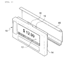
- FIG. 1 is an exploded perspective view showing a state in which an electronic tag and a guide rail are separated from each other, according to an exemplary embodiment of the present invention
- FIG. 2 is an exploded perspective view showing a state in which the electronic tag and a remover key are separated from each other, according to an exemplary embodiment of the present invention
- FIG. 3 is a perspective view showing a state in which the remover key is coupled to the electronic tag, according to an exemplary embodiment of the present invention
- FIGS. 4A and 4B are illustration views showing processes in which the electronic tag is separated from the guide rail by the remover key, according to an exemplary embodiment of the present invention
- FIG. 5 is an exploded perspective view showing a state in which an electronic tag and a guide rail are separated from each other, according to another exemplary embodiment of the present invention
- FIG. 6 is an exploded perspective view showing a state in which the electronic tag and a remover key are separated from each other, according to another exemplary embodiment of the present invention
- FIG. 7 is a perspective view showing a state in which the remover key is coupled to the electronic tag, according to another exemplary embodiment of the present invention
- FIGS. 8A and 8B are illustration views showing processes in which the electronic tag is separated from the guide rail by the remover key, according to another exemplary embodiment of the present invention.
- an electronic tag 10 is inserted into a guide rail 60 installed on a product display stand (not shown) of a distribution market so as to provide cost of the product and simple information related to the product.
- the above-mentioned electronic tag 10 includes a display part 12 on which contents related to the product is displayed and a case 14 coupled to the display part 12.
- the display part 12 may use an electronic paper or a display panel. Power supplement may be performed by a battery (not shown) installed on a rear surface of the electronic tag 10.
- the case 14 having the display part 12 coupled thereto is manufactured by injecting synthetic resin and may have at least one pair of guide protrusions 15 formed any one of upper or lower portion of a central portion of a circumference surface of the case 14.
- the pair of guide protrusions 15 is formed so that the electronic tag 10 is caught and slid in the guide rail 60 and the guide protrusion 15 may be configured in various shapes such as a rectangular shape, a semi-circular shape, a cylinder shape, or the like protruded toward an upper side.
- the pair of guide protrusions 15 may be formed at both end portions of the case 14 and the guide protrusions 15 formed at the central portion of the case 14 is more preferable than the guide protrusions 15 formed at both end portions of the case 14 when considering convenience according to separation and installation of the electronic tag 10.
- the pair of guide protrusions 15 may have a support protrusion 16 formed therebetween.
- the support protrusion 16 may be formed so as to have a size smaller than an interval between the pair of guide protrusions 15.
- the electronic tag 10 When the electronic tag 10 configured as described above is installed in the guide rail 60, the electronic tag 10 may be coupled to the guide rail 60 so that the guide protrusion 15 is inserted into a side of the guide rail 60 or may be installed so that the guide protrusion 15 is inserted into an inner side of the guide rail 60 by strongly pushing the electronic tag 10 toward the inner side of the guide rail 60 from a position on which a product is displayed.
- the manager uses a remover key 50.
- the remover key 50 which is configured by injecting a metal material or a synthetic resin material, includes a handle 52 and an extension part 55 formed to be extended from the handle 52.
- the handle 52 may be manufactured so as to have a length of about 10cm, which is a width of a palm of normal man so that the manager may conveniently grasp and use the handle 52.
- the extension part 55 includes extensions 56 in which both end portions rather than a central portion thereof are extended from the handle 52.
- the extensions 56 may be formed at both sides based on the center of the extension part 55 and may have a shape varied according to a shape and a position of the support protrusion 16 formed on the electronic tag 10.
- a length of the extension 56 may be changed according to a thickness of the electronic tag 10 and may be formed so as to be the same as or larger than the thickness of the electronic tag 10.
- the extension 56 has an inclined surface having a thickness that becomes thin toward a tip part thereof.
- the inclined surface 57 is configured so that the extension 56 is further conveniently inserted into between the electronic tag 10 and the guide rail 60.
- the manager grasps the handle 52 and allows the support protrusion 16 of the electronic tag to be inserted between the extensions 56 while inserting the inclined surface 57 into the inner side of the guide rail 60.
- the handle 52 is pressed in a downward direction.
- a rear surface of the extension part 55 presses an upper surface of the case 14 by a principle of a lever and the inclined surface 57 of the extensions lift the guide rail 60.
- the guide rail 60 is lifted, the guide protrusions 15 of the electronic tag is separated from the guide rail 60 by a predetermined interval.
- the manager grasps the electronic tag 10 with his or her hand and takes out it from the guide rail 60.
- the electronic tag 10 may be quickly and conveniently separated from the guide rail 60 in the case of using the remover key 50.
- FIGS. 5 to 8 show another exemplary embodiment of the present invention and the electronic tag 10 according to the exemplary embodiment of the present invention may be easily separated from the guide rail 60 by forming a remover groove 17 on the circumference surface of the case 14 and forming a plurality of ribs in the remover groove 17.
- the remover groove 17 may be formed at the central portion of the case 14.
- the remover groove 17 has a shape in which rear and upper surfaces of the case 14 are opened.
- the plurality of ribs 18 may be formed in the remover groove 17 while each having different intervals.
- the reason for forming the ribs 18 at different positions is to prevent the electronic tag 10 from being easily separated from the guide rail 60 using other tools other than the remover key 50 owned by the manager by configuring the remover key 50 and the remover groove 17 as a key and a lock.
- the remover key 50 may be configured by bending a central portion of the extension part 55.
- a bending angle may have a range less than 90°.
- the bending angle has a range of 90° or more, since an insertion angle of the remover key 50 becomes small in a process in which the remover key 50 is inserted into the remover groove 17, the usage of the remover key 50 may be further inconvenient.
- the remover key 50 is inserted into the electronic tag 10 so that the extension part 55 is coupled to each rib 18 of the remover groove by vertically putting down the remover key 50 on the upper portion of the electronic tag 10.
- the guide protrusions 15 of the electronic tag is separated from the guide rail 60.
- the manager takes out the electronic tag 10 from the guide rail 60 with his or her other hand.
- the electronic tag 10 may separate between the guide rail 60 and the electronic tag 10 by the principle of the lever in the case of forming the remover groove 17 on the upper portion of the case 14 and bending the shape of the remover key 50 at 90°.
- the electronic tag and the remover key of the electronic tag may easily install and separate the electronic tag on and from the displaying stand of the product, and particularly, may simultaneously anticipate convenience and durability according to the separation of the electronic tag.
- the electronic tag and the remover key of the electronic tag may increase efficiency in market management by preventing the electronic tag from being easily separated by a shopper using an arbitrary tool.
Landscapes
- Physics & Mathematics (AREA)
- General Physics & Mathematics (AREA)
- Engineering & Computer Science (AREA)
- Theoretical Computer Science (AREA)
- Cash Registers Or Receiving Machines (AREA)
- Push-Button Switches (AREA)
Abstract
Description
- This application claims the benefit of Korean Patent Application Serial No.
10-2013-0060434 - The present invention relates to an electronic tag and a remover key of the electronic tag, and more particularly, to an electronic tag installed in a distribution market and having a brand name, cost, or the like described thereon, and a remover key separating the electronic tag.
- In order to exhibit and sell a number of products in a predetermined space such as a distribution market, a label displaying information and cost of the products has been used.
- In general, the cost displaying label has been used in a scheme in which it is attached to a position in the vicinity of displayed product by directly handwriting product information necessary to sell the product, for example, cost and discount information on a paper or printing the product information on the paper so as to conform to a standardized form.
- A traditional scheme looks as if it may be simple, convenient, and implemented at low cost, but in the case in which the standardized forms are used for tens of thousands of product items or more as in a large-scaled distribution market and costs are frequently changed, there is a limit as to what an existing paper label scheme is applied.
- That is, if changes in costs of some product items among a number of product items have occurred, after a manager summarizes the changed costs and handwrites or prints the product information such as the changed costs, the manager has to go to where the corresponding products are sold and exhibited in the distribution market so as to replace the labels.
- Therefore, time and workers for performing the above-mentioned work and replacement whenever the cost information of the product is changed have required and a need for improving the above-mentioned problems has increased due to nature of the large-scaled distribution market.
- In recent, the existing paper label has significantly replaced with an electronic tag based on the above-mentioned market requirement.
- The electronic tag is inserted into a guide rail of a display stand on which the product is displayed and is then moved along the guide rail so as to be disposed at a center of a place on which the product is placed.
- When separating the electronic tag from the guide rail, the electronic tag may be separated from the guide rail by manipulating a stopper installed on a side of the electronic tag using a remover key.
- However, the remover key of separating the electronic tag from the guide rail separates the electronic tag from the guide rail by lifting a lower end of the electronic tag in a state in which the remover key is inserted into the stopper of the electronic tag. In this process, a tip of the remover key may be damaged by excessive force of a user.
- In addition, since the stopper of the electronic tag is elastically supported by a spring, a position of the electronic tag is adjusted after lifting the stopper using the remover key. However, in this case, it is difficult to finely adjust the position of the electronic tag.
- (Patent Document 1) Cited Reference: Korean Patent Laid-Open Publication No.
1999-0005966 - An object of the present invention is to provide an electronic tag and a remover key of the electronic tag capable of easily installing and separating the electronic tag on and from a displaying stand of a product, and particularly, simultaneously anticipating convenience and durability according to the separation of the electronic tag.
- Another object of the present invention is to provide an electronic tag and a remover key of the electronic tag capable of efficiency of management by preventing the electronic tag from being easily separated by an arbitrary tool.
- According to an exemplary embodiment of the present invention, there is provided an electronic tag installed in a guide rail of a product display stand, the electronic tag including: a display part and a case coupled to the display part; at least a pair of guide protrusions formed on a circumference surface of the case so as to be inserted into the guide rail and slid in the guide rail; and a support protrusion formed between the pair of guide protrusions of the case.
- According to another exemplary embodiment of the present invention, there is provided an electronic tag installed in a guide rail of a product display stand, the electronic tag including: a display part and a case coupled to the display part; at least a pair of guide protrusions formed on a circumference surface of the case so as to be inserted into the guide rail and slid in the guide rail; a remover groove formed between the pair of guide protrusions of the case; and a rib formed in the remover groove of the case.
- The remover groove may be configured in a shape in which a rear surface and an upper surface of the case are opened and the rib configured in the remover groove may be plural.
- The remover groove may be provided with a plurality of ribs having different intervals from each other.
- According to another exemplary embodiment of the present invention, there is provided a remover key installed in a guide rail of a product display stand and separating an electronic tag having a plurality of ribs formed therein, the remover key including: a handle and an extension part, wherein the extension part has a plurality of extensions formed so as to be coupled to the rib of the electronic tag.
- The extension part may have a plurality of extensions formed so as to have different intervals therebetween.
- The extension may be provided with an inclined surface having a thickness that becomes thin toward a tip part thereof and the extension may be configured to be bent.
-
-
FIG. 1 is an exploded perspective view showing a state in which an electronic tag and a guide rail are separated from each other according to an exemplary embodiment of the present invention; -
FIG. 2 is an exploded perspective view showing a state in which the electronic tag and a remover key are separated from each other according to the exemplary embodiment of the present invention; -
FIG. 3 is a perspective view showing a state in which the remover key is coupled to the electronic tag according to the exemplary embodiment of the present invention; -
FIGS. 4A and4B are illustration views showing processes in which the electronic tag is separated from the guide rail by the remover key according to the exemplary embodiment of the present invention; -
FIG. 5 is an exploded perspective view showing a state in which an electronic tag and a guide rail are separated from each other according to another exemplary embodiment of the present invention; -
FIG. 6 is an exploded perspective view showing a state in which the electronic tag and a remover key are separated from each other, according to another exemplary embodiment of the present invention; -
FIG. 7 is a perspective view showing a state in which the remover key is coupled to the electronic tag according to another exemplary embodiment of the present invention; and -
FIGS. 8A and 8B are illustration views showing processes in which the electronic tag is separated from the guide rail by the remover key, according to another exemplary embodiment of the present invention. - Hereinafter, exemplary embodiments of the present invention will be described in detail with reference to the accompanying drawings.
-
FIG. 1 is an exploded perspective view showing a state in which an electronic tag and a guide rail are separated from each other, according to an exemplary embodiment of the present invention,FIG. 2 is an exploded perspective view showing a state in which the electronic tag and a remover key are separated from each other, according to an exemplary embodiment of the present invention,FIG. 3 is a perspective view showing a state in which the remover key is coupled to the electronic tag, according to an exemplary embodiment of the present invention,FIGS. 4A and4B are illustration views showing processes in which the electronic tag is separated from the guide rail by the remover key, according to an exemplary embodiment of the present invention,FIG. 5 is an exploded perspective view showing a state in which an electronic tag and a guide rail are separated from each other, according to another exemplary embodiment of the present invention,FIG. 6 is an exploded perspective view showing a state in which the electronic tag and a remover key are separated from each other, according to another exemplary embodiment of the present invention,FIG. 7 is a perspective view showing a state in which the remover key is coupled to the electronic tag, according to another exemplary embodiment of the present invention, andFIGS. 8A and 8B are illustration views showing processes in which the electronic tag is separated from the guide rail by the remover key, according to another exemplary embodiment of the present invention. - As shown in
FIGS. 1 to 4 , anelectronic tag 10 according to an exemplary embodiment of the present invention is inserted into aguide rail 60 installed on a product display stand (not shown) of a distribution market so as to provide cost of the product and simple information related to the product. - The above-mentioned
electronic tag 10 includes adisplay part 12 on which contents related to the product is displayed and acase 14 coupled to thedisplay part 12. - The
display part 12 may use an electronic paper or a display panel. Power supplement may be performed by a battery (not shown) installed on a rear surface of theelectronic tag 10. - The
case 14 having thedisplay part 12 coupled thereto is manufactured by injecting synthetic resin and may have at least one pair ofguide protrusions 15 formed any one of upper or lower portion of a central portion of a circumference surface of thecase 14. - The pair of
guide protrusions 15 is formed so that theelectronic tag 10 is caught and slid in theguide rail 60 and theguide protrusion 15 may be configured in various shapes such as a rectangular shape, a semi-circular shape, a cylinder shape, or the like protruded toward an upper side. - In this case, the pair of
guide protrusions 15 may be formed at both end portions of thecase 14 and theguide protrusions 15 formed at the central portion of thecase 14 is more preferable than theguide protrusions 15 formed at both end portions of thecase 14 when considering convenience according to separation and installation of theelectronic tag 10. - In addition, the pair of
guide protrusions 15 may have asupport protrusion 16 formed therebetween. Thesupport protrusion 16 may be formed so as to have a size smaller than an interval between the pair ofguide protrusions 15. - When the
electronic tag 10 configured as described above is installed in theguide rail 60, theelectronic tag 10 may be coupled to theguide rail 60 so that theguide protrusion 15 is inserted into a side of theguide rail 60 or may be installed so that theguide protrusion 15 is inserted into an inner side of theguide rail 60 by strongly pushing theelectronic tag 10 toward the inner side of theguide rail 60 from a position on which a product is displayed. - However, since the method in which the
guide protrusion 15 is inserted into the inner side of theguide rail 60 may damage theguide protrusion 15 by theguide rail 60, a method in which theguide protrusion 15 is inserted from the side of theguide rail 60 and is moved will be safe. - After the
electronic tag 10 is installed as described above, when a manager separates theelectronic tag 10 from theguide rail 60, the manager uses aremover key 50. - The
remover key 50, which is configured by injecting a metal material or a synthetic resin material, includes ahandle 52 and anextension part 55 formed to be extended from thehandle 52. - The
handle 52 may be manufactured so as to have a length of about 10cm, which is a width of a palm of normal man so that the manager may conveniently grasp and use thehandle 52. - The
extension part 55 includesextensions 56 in which both end portions rather than a central portion thereof are extended from thehandle 52. Theextensions 56 may be formed at both sides based on the center of theextension part 55 and may have a shape varied according to a shape and a position of thesupport protrusion 16 formed on theelectronic tag 10. - In addition, a length of the
extension 56 may be changed according to a thickness of theelectronic tag 10 and may be formed so as to be the same as or larger than the thickness of theelectronic tag 10. - In addition, the
extension 56 has an inclined surface having a thickness that becomes thin toward a tip part thereof. Theinclined surface 57 is configured so that theextension 56 is further conveniently inserted into between theelectronic tag 10 and theguide rail 60. - When the
electronic tag 10 is separated from theguide rail 60 using the remover key 50 according to the exemplary embodiment of the present invention, the manager grasps thehandle 52 and allows thesupport protrusion 16 of the electronic tag to be inserted between theextensions 56 while inserting theinclined surface 57 into the inner side of theguide rail 60. - Once the
extensions 56 are inserted between theguide rail 60 and theelectronic tag 10, thehandle 52 is pressed in a downward direction. When thehandle 52 is pressed, a rear surface of theextension part 55 presses an upper surface of thecase 14 by a principle of a lever and theinclined surface 57 of the extensions lift theguide rail 60. Theguide rail 60 is lifted, theguide protrusions 15 of the electronic tag is separated from theguide rail 60 by a predetermined interval. - Once the guide rail is separated from an upper portion of the
electronic tag 10, the manager grasps theelectronic tag 10 with his or her hand and takes out it from theguide rail 60. - Therefore, the
electronic tag 10 according to the exemplary embodiment of the present invention may be quickly and conveniently separated from theguide rail 60 in the case of using theremover key 50. - Meanwhile,
FIGS. 5 to 8 show another exemplary embodiment of the present invention and theelectronic tag 10 according to the exemplary embodiment of the present invention may be easily separated from theguide rail 60 by forming aremover groove 17 on the circumference surface of thecase 14 and forming a plurality of ribs in theremover groove 17. - More specifically, the
remover groove 17 may be formed at the central portion of thecase 14. Theremover groove 17 has a shape in which rear and upper surfaces of thecase 14 are opened. The plurality ofribs 18 may be formed in theremover groove 17 while each having different intervals. - The reason for forming the
ribs 18 at different positions is to prevent theelectronic tag 10 from being easily separated from theguide rail 60 using other tools other than the remover key 50 owned by the manager by configuring the remover key 50 and theremover groove 17 as a key and a lock. - In this case, the remover key 50 may be configured by bending a central portion of the
extension part 55. A bending angle may have a range less than 90°. In the case in which the bending angle has a range of 90° or more, since an insertion angle of the remover key 50 becomes small in a process in which theremover key 50 is inserted into theremover groove 17, the usage of the remover key 50 may be further inconvenient. - When the
electronic tag 10 is separated from theguide rail 60 by inserting the remover key 50 into theelectronic tag 10, theremover key 50 is inserted into theelectronic tag 10 so that theextension part 55 is coupled to eachrib 18 of the remover groove by vertically putting down the remover key 50 on the upper portion of theelectronic tag 10. - In this state, once the remover key 50 is pressed in a direction opposite to a direction in which the
guide rail 60 is positioned, the end portions of theextensions 56 lift theguide rail 60 around the bending part of theextension part 55. - Once the
guide rail 60 is lifted, theguide protrusions 15 of the electronic tag is separated from theguide rail 60. Once theelectronic tag 10 is separated from theguide rail 60, the manager takes out theelectronic tag 10 from theguide rail 60 with his or her other hand. - As such, the
electronic tag 10 according to the exemplary embodiment of the present invention may separate between theguide rail 60 and theelectronic tag 10 by the principle of the lever in the case of forming theremover groove 17 on the upper portion of thecase 14 and bending the shape of the remover key 50 at 90°. - The electronic tag and the remover key of the electronic tag according to the exemplary embodiment of the present invention may easily install and separate the electronic tag on and from the displaying stand of the product, and particularly, may simultaneously anticipate convenience and durability according to the separation of the electronic tag.
- In addition, the electronic tag and the remover key of the electronic tag according to the exemplary embodiment of the present invention may increase efficiency in market management by preventing the electronic tag from being easily separated by a shopper using an arbitrary tool.
- Hereinabove, although the electronic tag and the remover key of the electronic tag according to the exemplary embodiments of the present invention have been described, the present invention is not limited thereto, but may be variously modified and altered by those skilled in the art.
Claims (9)
- An electronic tag installed in a guide rail of a product display stand, the electronic tag comprising:a display part and a case coupled to the display part;at least a pair of guide protrusions formed on a circumference surface of the case so as to be inserted into the guide rail and slid in the guide rail; anda support protrusion formed between the pair of guide protrusions of the case.
- An electronic tag installed in a guide rail of a product display stand, the electronic tag comprising:a display part and a case coupled to the display part;at least a pair of guide protrusions formed on a circumference surface of the case so as to be inserted into the guide rail and slid in the guide rail;a remover groove formed between the pair of guide protrusions of the case; anda rib formed in the remover groove of the case.
- The electronic tag according to claim 2, wherein the remover groove is configured in a shape in which a rear surface and an upper surface of the case are opened.
- The electronic tag according to claim 2, wherein the rib configured in the remover groove is plural.
- The electronic tag according to claim 2 or 4, wherein the remover groove is provided with a plurality of ribs having different intervals from each other.
- A remover key installed in a guide rail of a product display stand and separating an electronic tag having a plurality of ribs formed therein, the remover key comprising:a handle and an extension part,wherein the extension part has a plurality of extensions formed so as to be coupled to the rib of the electronic tag.
- The remover key of the electronic tag according to claim 6, wherein the extension part has a plurality of extensions formed so as to have different intervals therebetween.
- The remover key of the electronic tag according to claim 7, wherein the extension is provided with an inclined surface having a thickness that becomes thin toward a tip part thereof.
- The remover key of the electronic tag according to claim 6, wherein the extension is configured to be bent.
Applications Claiming Priority (1)
| Application Number | Priority Date | Filing Date | Title |
|---|---|---|---|
| KR1020130060434A KR102069760B1 (en) | 2013-05-28 | 2013-05-28 | Electronic tag and remover key of electronic tag |
Publications (1)
| Publication Number | Publication Date |
|---|---|
| EP2808861A1 true EP2808861A1 (en) | 2014-12-03 |
Family
ID=49554173
Family Applications (1)
| Application Number | Title | Priority Date | Filing Date |
|---|---|---|---|
| EP13275263.5A Withdrawn EP2808861A1 (en) | 2013-05-28 | 2013-10-29 | Electronic tag and remover key of electronic tag |
Country Status (2)
| Country | Link |
|---|---|
| EP (1) | EP2808861A1 (en) |
| KR (1) | KR102069760B1 (en) |
Cited By (1)
| Publication number | Priority date | Publication date | Assignee | Title |
|---|---|---|---|---|
| WO2026017241A1 (en) * | 2024-07-16 | 2026-01-22 | Vusiongroup Gmbh | Fastening system for fastening electronic display devices for presenting product information |
Citations (5)
| Publication number | Priority date | Publication date | Assignee | Title |
|---|---|---|---|---|
| EP0683478A2 (en) * | 1994-05-17 | 1995-11-22 | NCR International, Inc. | An electronic shelf label mounting system |
| WO1999003174A1 (en) * | 1997-07-11 | 1999-01-21 | The Whitaker Corporation | Electrical connection assembly for rail mounted display |
| KR19990005966A (en) | 1997-06-30 | 1999-01-25 | 김영환 | High speed data transmission device of wireless local area network |
| GB2462334A (en) * | 2008-08-08 | 2010-02-10 | Samsung Electro Mech | Electronic shelf label lockably attached to a shelf |
| US20100088937A1 (en) * | 2008-10-15 | 2010-04-15 | Samsung Electro-Mechanics Co., Ltd. | Price display apparatus |
-
2013
- 2013-05-28 KR KR1020130060434A patent/KR102069760B1/en active Active
- 2013-10-29 EP EP13275263.5A patent/EP2808861A1/en not_active Withdrawn
Patent Citations (5)
| Publication number | Priority date | Publication date | Assignee | Title |
|---|---|---|---|---|
| EP0683478A2 (en) * | 1994-05-17 | 1995-11-22 | NCR International, Inc. | An electronic shelf label mounting system |
| KR19990005966A (en) | 1997-06-30 | 1999-01-25 | 김영환 | High speed data transmission device of wireless local area network |
| WO1999003174A1 (en) * | 1997-07-11 | 1999-01-21 | The Whitaker Corporation | Electrical connection assembly for rail mounted display |
| GB2462334A (en) * | 2008-08-08 | 2010-02-10 | Samsung Electro Mech | Electronic shelf label lockably attached to a shelf |
| US20100088937A1 (en) * | 2008-10-15 | 2010-04-15 | Samsung Electro-Mechanics Co., Ltd. | Price display apparatus |
Cited By (2)
| Publication number | Priority date | Publication date | Assignee | Title |
|---|---|---|---|---|
| WO2026017241A1 (en) * | 2024-07-16 | 2026-01-22 | Vusiongroup Gmbh | Fastening system for fastening electronic display devices for presenting product information |
| WO2026017496A1 (en) | 2024-07-16 | 2026-01-22 | Vusiongroup Gmbh | Module for detachable fastening to a holding device |
Also Published As
| Publication number | Publication date |
|---|---|
| KR102069760B1 (en) | 2020-01-23 |
| KR20140139828A (en) | 2014-12-08 |
| KR102069760B9 (en) | 2024-03-06 |
Similar Documents
| Publication | Publication Date | Title |
|---|---|---|
| US20150266611A1 (en) | Tamper evident containers with lid tabs | |
| US9757848B2 (en) | Detaching equipment for detaching electronic device and detaching method thereof | |
| US20090083945A1 (en) | Paper clip | |
| US9370870B2 (en) | Raising apparatus | |
| TWD138655S1 (en) | Data Entry Machine | |
| EP2425750B1 (en) | Electronic shelf label | |
| US20170050759A1 (en) | Packing box | |
| US20060175222A1 (en) | Collapsible dispenser box holder | |
| EP2808835A1 (en) | Electronic tag remote control | |
| US9185978B1 (en) | Drawer handle with releasable protective member | |
| US8404053B2 (en) | Device and method for removing particulates from a keyboard | |
| US20140310954A1 (en) | Wrench for memory card | |
| KR102069760B1 (en) | Electronic tag and remover key of electronic tag | |
| CA2772401A1 (en) | Identification tag with resilient fingers | |
| US6809921B2 (en) | Mechanism for attaching a detachable panel to a housing of a PDA | |
| JP3168375U (en) | Card holder | |
| CN205548029U (en) | Furniture spare function element and furniture spare | |
| WO2014018995A2 (en) | File note device | |
| US20100193454A1 (en) | Display Hanger for Through Hole Attachment | |
| CN107403586A (en) | Supporting equipment for electronic tags | |
| US5144763A (en) | Stand for displaying computer keyboard function key guides | |
| CN208240270U (en) | A kind of electronic tag back buckle folder | |
| JP3186408U (en) | Electronic shelf label and POP indicator attached to it | |
| GB2496381A (en) | A touch pen with replaceable nib | |
| JP3198951U (en) | Blade type fixture |
Legal Events
| Date | Code | Title | Description |
|---|---|---|---|
| PUAI | Public reference made under article 153(3) epc to a published international application that has entered the european phase |
Free format text: ORIGINAL CODE: 0009012 |
|
| 17P | Request for examination filed |
Effective date: 20131029 |
|
| AK | Designated contracting states |
Kind code of ref document: A1 Designated state(s): AL AT BE BG CH CY CZ DE DK EE ES FI FR GB GR HR HU IE IS IT LI LT LU LV MC MK MT NL NO PL PT RO RS SE SI SK SM TR |
|
| AX | Request for extension of the european patent |
Extension state: BA ME |
|
| R17P | Request for examination filed (corrected) |
Effective date: 20150603 |
|
| RBV | Designated contracting states (corrected) |
Designated state(s): AL AT BE BG CH CY CZ DE DK EE ES FI FR GB GR HR HU IE IS IT LI LT LU LV MC MK MT NL NO PL PT RO RS SE SI SK SM TR |
|
| STAA | Information on the status of an ep patent application or granted ep patent |
Free format text: STATUS: THE APPLICATION HAS BEEN WITHDRAWN |
|
| 18W | Application withdrawn |
Effective date: 20161031 |