EP2808748A1 - Data setting device - Google Patents
Data setting device Download PDFInfo
- Publication number
- EP2808748A1 EP2808748A1 EP12866546.0A EP12866546A EP2808748A1 EP 2808748 A1 EP2808748 A1 EP 2808748A1 EP 12866546 A EP12866546 A EP 12866546A EP 2808748 A1 EP2808748 A1 EP 2808748A1
- Authority
- EP
- European Patent Office
- Prior art keywords
- data
- plc
- variable
- frame
- written
- Prior art date
- Legal status (The legal status is an assumption and is not a legal conclusion. Google has not performed a legal analysis and makes no representation as to the accuracy of the status listed.)
- Granted
Links
Images
Classifications
-
- G—PHYSICS
- G05—CONTROLLING; REGULATING
- G05B—CONTROL OR REGULATING SYSTEMS IN GENERAL; FUNCTIONAL ELEMENTS OF SUCH SYSTEMS; MONITORING OR TESTING ARRANGEMENTS FOR SUCH SYSTEMS OR ELEMENTS
- G05B19/00—Program-control systems
- G05B19/02—Program-control systems electric
- G05B19/04—Program control other than numerical control, i.e. in sequence controllers or logic controllers
- G05B19/05—Programmable logic controllers, e.g. simulating logic interconnections of signals according to ladder diagrams or function charts
- G05B19/056—Programming the PLC
-
- G—PHYSICS
- G05—CONTROLLING; REGULATING
- G05B—CONTROL OR REGULATING SYSTEMS IN GENERAL; FUNCTIONAL ELEMENTS OF SUCH SYSTEMS; MONITORING OR TESTING ARRANGEMENTS FOR SUCH SYSTEMS OR ELEMENTS
- G05B19/00—Program-control systems
- G05B19/02—Program-control systems electric
- G05B19/04—Program control other than numerical control, i.e. in sequence controllers or logic controllers
- G05B19/05—Programmable logic controllers, e.g. simulating logic interconnections of signals according to ladder diagrams or function charts
- G05B19/054—Input/output
-
- H—ELECTRICITY
- H04—ELECTRIC COMMUNICATION TECHNIQUE
- H04L—TRANSMISSION OF DIGITAL INFORMATION, e.g. TELEGRAPHIC COMMUNICATION
- H04L12/00—Data switching networks
- H04L12/28—Data switching networks characterised by path configuration, e.g. LAN [Local Area Networks] or WAN [Wide Area Networks]
- H04L12/40—Bus networks
- H04L12/40169—Flexible bus arrangements
-
- H—ELECTRICITY
- H04—ELECTRIC COMMUNICATION TECHNIQUE
- H04L—TRANSMISSION OF DIGITAL INFORMATION, e.g. TELEGRAPHIC COMMUNICATION
- H04L12/00—Data switching networks
- H04L12/28—Data switching networks characterised by path configuration, e.g. LAN [Local Area Networks] or WAN [Wide Area Networks]
- H04L12/40—Bus networks
- H04L12/403—Bus networks with centralised control, e.g. polling
- H04L12/4035—Bus networks with centralised control, e.g. polling in which slots of a TDMA packet structure are assigned based on a contention resolution carried out at a master unit
-
- G—PHYSICS
- G05—CONTROLLING; REGULATING
- G05B—CONTROL OR REGULATING SYSTEMS IN GENERAL; FUNCTIONAL ELEMENTS OF SUCH SYSTEMS; MONITORING OR TESTING ARRANGEMENTS FOR SUCH SYSTEMS OR ELEMENTS
- G05B2219/00—Program-control systems
- G05B2219/10—Plc systems
- G05B2219/13—Plc programming
- G05B2219/13004—Programming the plc
-
- H—ELECTRICITY
- H04—ELECTRIC COMMUNICATION TECHNIQUE
- H04L—TRANSMISSION OF DIGITAL INFORMATION, e.g. TELEGRAPHIC COMMUNICATION
- H04L12/00—Data switching networks
- H04L12/28—Data switching networks characterised by path configuration, e.g. LAN [Local Area Networks] or WAN [Wide Area Networks]
- H04L12/40—Bus networks
- H04L2012/4026—Bus for use in automation systems
Definitions
- the present invention relates to a technology of rewriting a variable set in a PLC through a network.
- an industrial network system controls production facilities.
- a plurality of slave devices which perform control of various production facilities and data collection and a master device (PLC: Programmable Logic Controller) that centrally controls the slave devices are connected to each other through a control-system network (field network).
- PLC Programmable Logic Controller
- the PLC installed in a production line or a production site is connected to a host computer through an information-system network, and a system manager or an engineer can perform state monitoring or maintenance of each industrial network system with the computer.
- a data type of the setting variable is roughly classified into a fixed-length data type such as an int type (integer type) and a real type and a variable-length data type such as a string type (character string type).
- a fixed-length data type such as an int type (integer type)
- a real type such as a real type
- a variable-length data type such as a string type (character string type).
- an upper limit size of the variable-length data such as the string type is restricted to a relatively small value (for example, 256 bytes).
- the upper limit size is restricted is a constraint of a maximum frame length (a frame size transmittable in one-time data transmission) in the industrial network.
- the maximum frame length is as quite small as about 500 bytes in DeviceNet or CompoNet that is a typical control-system network.
- it is necessary to read or rewrite the setting variable from the external computer. Therefore, as described above, it is necessary to restrict the upper limit size to about 256 bytes.
- IP fragmentation In the framework (IP fragmentation) of general TCP/IP communication, in the case that a size of an IP packet exceeds an MTU (Maximum Transmission Unit), the IP packet is transmitted while divided into a plurality of packets, the individually-received packets are combined to restore the original packet on the reception side based on header information (for example, see Patent Document 1).
- the fragmentation framework is not prepared for a protocol (for example, CIP (Common Industrial Protocol)) generally used in the industrial network.
- Patent Document 1 JP2001-313675A
- the variable having the size larger than the maximum frame length is rewritten from the external computer, it is necessary to adopt a method of transmitting the data while dividing the data into a plurality of frames.
- the variable in a memory is safely overwritten through a procedure in which the variable is overwritten after the original data is restored on the PLC side by combining the pieces of data received multiple times.
- the procedure is hardly employed on the protocol for the industrial network.
- the protocol for the industrial network is designed with more emphasis on a real-time property and transmission efficiency, but the protocol for the industrial network does not include the framework like session management in terms of TCP/IP. Therefore, whether all the pieces of divided data are unmistakably received on the PLC side cannot be determined or guaranteed.
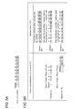
- Fig. 5 illustrates an example of the procedure.
- Fig. 5A illustrates the data written in the PLC
- Fig. 5B illustrates the frame transmitted from the computer and s memory state of the PLC in time series.
- the procedure to set a character string "ABCDEFG" to a variable "abc" is illustrated in Fig. 5 .
- the data size transmittable in one frame is 5 bytes.
- 10 bytes are assigned as the data area for the variable "abc" to the memory of the PLC, and it is assumed that the a character string "123456" is stored in an initial state.
- the write data is the string type data, and the write data is constructed with 8 bytes of character codes "41, 42, 43, 44, 45, 46, and 47" of each of "A, B, C, D, E, F, and G” and a null code "00" of a terminal character.
- the write data is transmitted in twice because only 5 bytes can be transmitted in one frame.
- 5-byte data codes of five characters "ABCDE" from the head is transmitted together with an offset "0".
- the PLC When receiving the frame, the PLC writes the character codes of "ABCDE” in the address of the offset "0" of the variable "abc".
- the remaining 3-byte data (the character codes of "FG” and the code of the terminal character) is transmitted together with the offset "5".
- the PLC writes the character codes of "FG” and the code of the terminal character in the address of the offset "5" of the variable "abc". Therefore, the rewrite of the setting variable in the memory of the PLC is completed.
- the procedure in Fig. 5 is simple, and the procedure is easily employed on the industrial network.
- the procedure in Fig. 5 there is a risk of generating the following problem.
- the data area of the variable "abc" of the PLC becomes a state "ABCDE6" in a transition period until the data of the second frame is written since the data of the first frame is written.
- the character string "ABCDE6" is improper data
- the character string "ABCDE6” is pursuant to a string type data structure. Therefore, whether the data is improper cannot be determined on the PLC side.
- an object of the invention is to provide a technology of simply and safely writing the variable-length data in the PLC.
- a terminal code is written in a head of a data area of a PLC, and head data is finally written after all pieces of data except the head data are sequentially written, whereby the data area is recognized as empty data during a transition period.
- a data setting device configured to rewrite a variable set in a PLC through a network
- the data setting device includes a data setting section configured to generates a frame, and to cause the PLC to rewrite a rewriting target variable by transmitting the frame to the PLC, the frame indicating at least the rewriting target variable, an offset from a head address of a data area of the rewriting target variable, and data to be written at a position designated by the offset.
- the data setting section divides the data to be written into a plurality of pieces of divided data of the maximum size or less to calculate the offset of each piece of divided data, transmits a frame issuing an instruction to the PLC to write the predetermined terminal code in the head address of the data area, transmits a frame issuing an instruction to the PLC to write the divided data at a position of the corresponding offset from the head address of the data area with respect to the divided data except a head divided data, and transmits a frame issuing an instruction to the PLC to write the head divided data in the head address of the data area.
- a state in which the terminal data is set to the head address of the data area is maintained during a transition period of the data write, namely, until the write of the final divided data is completed since the data write is started. Accordingly, even if the PLC refers to the variable during the transition period, the PLC recognizes that the variable is empty (the data is not set). For the empty variable, although the operation depends on design of the PLC, at least abnormal operation (unintended operation) caused by improper data can be prevented before it happens.
- the abnormal operation is prevented during the transition period of the data write, so that the data setting section can safely rewrite the variable during the operation of the PLC.
- the variable may be a character string type variable terminated by a null code.
- the network may be an industrial network, and a protocol used to transmit the frame may be a protocol including no fragmentation mechanism.
- the invention in which rewrite is performed by the division transmission can preferably be applied to the industrial network because the maximum size transmittable in one frame is relatively small in the industrial network.
- the invention can also be identified as a data setting device including at least a part of the data setting section, or identified as a data setting system including the data setting device and the PLC.
- the invention can also be identified as a data setting method in which a computer performs at least a part of the pieces of processing, identified as a program causing the computer to perform at least a part of the pieces of processing, or identified as a computer-readable storage medium in which the program is stored.
- the pieces of processing and the sections can freely be combined as long as technical inconsistency is generated.
- variable-length data can simply and safely be written in the PLC.
- the string type variable is rewritten using message communication of CIP between a computer (data setting device) and the PLC that are connected to each other through EtherNet/IP.
- the invention is not limited to the embodiment.
- the invention can preferably be applied irrespective of the network, the protocol, and the data type as long as a variable-length data type variable terminated by a predetermined terminal code is rewritten through the network.
- the upper limit of the transmittable frame size is small in the special-field network such as the industrial network, and the special-field network does not include a mechanism of session management or fragmentation. Therefore, the invention can preferably be applied to the special-field network.
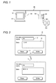
- the industrial network system in Fig. 1 includes a PLC (Programmable Logic Controller) 200 and a plurality of slave devices 300.
- the PLC 200 and the slave device 300 are connected to each other through a control-system network NW2 or an internal bus.
- Examples of the slave devices 300 include a power supply unit, a motor unit, a counter unit, an image unit, a communication unit, and an I/O unit.
- the industrial network system is used to control of various production facilities (such as motors, robots, and sensors) and collect various pieces of data in a production line of a factory.
- the PLC 200 is connected to a computer 100 through an information-system network NW1.
- the computer 100 is used when a system manager monitors a state of each base or when an engineer performs online maintenance of the PLC 200 or the slave device 300.
- a general-purpose personal computer including a display device 101 and an input device 102 can be used as the computer 100.
- a CPU executes a program stored in a storage device of the computer 100, thereby implementing a later-described function (data setting section) of reading/writing of a PLC setting variable.
- Various pieces of information used in a control program such as a ladder program are stored as setting variables in a memory of the PLC 200, and the setting variables are written or rewritten from the computer 100, which allows change or correction (debugging) of operation of the PLC 200 or the slave device 300.
- Examples of the data types of the setting variables include a boolean type (logic type), an int type (integer type), a real type, a byte type, a word type, and a string type (character string type).
- the pieces of data of the boolean type, the Int type, the real type, the byte type, and the word type are fixed lengths, and the boolean type, the Int type, the real type, the byte type, and the word type have data sizes of 1 byte, 2 bytes, 4 bytes, 1 byte, and 2 bytes, respectively.
- the data of the string type is a variable length, and the string type has the data size up to 1986 bytes.
- a character string terminated by a null character is stored in the string type variable.
- the data having about 660 characters can be set to the string type variable for a 3-byte character like Japanese, and the data having about 500 characters can be set to the string type variable for a 4-byte character like Chinese.
- This specification is illustrated by way of example, and a variable-length data type having the data size of several kilobytes to several megabytes can also be provided.
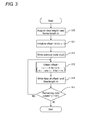
- Fig. 2 illustrates an example of an operation screen for a function of reading/writing a PLC setting variable
- the operation screen is provided by an application program (tool) operating on the computer 100.
- an application program tool
- FIG. 2 illustrates an example of an operation screen for a function of reading/writing a PLC setting variable
- the operation screen is provided by an application program (tool) operating on the computer 100.
- an operation screen 20 in Fig. 2 is displayed on the display device 101.
- the computer 100 acquires a present value of the variable from the PLC 200 and displays the present value in the box 22.
- An upper stage of Fig. 2 illustrates an example in which a present value "123456" of a variable "abc" is checked.
- the variable name is input to the box 21, the data to be written is input to the box 22, and a write button 24 is pressed. Therefore, the computer 100 transmits a request to write the variable to the PLC 200, and the data of the memory is rewritten in the PLC 200.
- a lower stage of Fig. 2 illustrates an example in which the value of the variable "abc" is rewritten into "ABCDEFG".
- variable is written in the PLC 200 using a variable writing request that is of one of services provided by the CIP.
- a message of the request includes a service ID, a class ID, the variable name, an offset, and the data to be written.
- the "service ID” and the "class ID” designate variable writing processing.
- the "variable name” designates the name of the variable that becomes a writing target, and the "offset” designates which byte from a head address of a data area of the variable the data is written in.
- the request message in which the variable name "abc", an offset "4", and data "EFG” are designated is transmitted to the PLC 200, the data "EFG" is written at the position of 4 bytes from the head address of the data area of the variable "abc" in the memory of the PLC 200.
- the memory of the PLC 200 can basically be rewritten using the variable writing request.
- the processing is performed multiple times while the variable writing request is divided depending on the data size. A procedure in this case will be described in detail below.
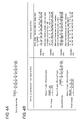
- Fig. 3 is a flowchart illustrating processing of the computer 100 when the data is transmitted using the plurality of frames.
- Fig. 4A illustrates the data written in the PLC 200
- Fig. 4B illustrates the frame transmitted from the computer 100 and a memory state of the PLC 200 in time series.
- the procedure to set the character string "ABCDEFG" to the variable "abc" is described by way of example. Like the example in Fig.
- the computer 100 acquires a data length I of the character string data to be written and a maximum size (frame length) m transmittable in one frame (Step S10), and the computer 100 initializes an offset i to I (Step S11).
- the computer 100 writes a terminal code (null) in the head address of the data area of the rewriting target variable of the PLC 200 (before the actual character string data is written) (Step S12). Specifically, a frame having the offset "0" and the data "00 (null)" is generated as illustrated in Fig. 4B , and transmitted to the PLC 200. In response to the request, the PLC 200 writes null in the head address of the data area of the variable "abc".
- the character string data is divided into a plurality of pieces of divided data of the maximum size or less, and the pieces of divided data are sequentially written from the end.
- the value of the offset i is updated so as to be decremented by m (however, for i ⁇ m, m is substituted for i and o is substituted for i) (Step S13)
- the divided data of m bytes from an ith byte of the original character string data is written at the position of the ith byte from the head of the data area (Step S14).
- the pieces of processing in Steps S13 and S14 are repeated until all the pieces of data are written (Step S15).
- the PLC 200 recognizes that the variable is empty (the data is not set).
- the operation of the control program of the PLC 200 is designed such that "for the empty variable, an abnormality is determined to be generated to output an error message" or such that "for the empty variable, the processing is performed using a default value", whereby abnormal operation (unintended operation) of the PLC 200 can be prevented.
- the character string to be printed is changed according to a product or a lot, the image data of each pattern is previously prepared, and the character string is switched by designating an image ID or the like.
- the character string to be printed can be dealt with as the variable. In this case, maintenance is facilitated because the character string to be printed can be changed or added from an external computer or an HMI (Human Machine Interface).
- HMI Human Machine Interface
- an error message (a warning statement or a descriptive statement) is generated on the computer or HMI side based on an error number acquired from the PLC.
- the computer or the HMI it is necessary for the computer or the HMI to have dictionary data in which the error number and the error message are associated with each other.
- the error message can be included as the variable in the PLC. Therefore, the system can flexibly be designed because the necessity of the dictionary data is eliminated in the computer or the HMI.
- production data is stored in a text file format in a memory card attached to the PLC.
- the character strings of a model, a lot number, and the like are previously set as the variable in the PLC.
- an error log is recorded in the memory card, and the error message described in a log is also set as the variable in the PLC.
- a text file such as recipe information is read from the memory card and set in the PLC.
- a multi-byte character such as Chinese is dealt with, the conventional size (for example, 256 bytes) is not enough.
- the multi-byte character can easily be dealt with when the character string of several kilobytes can be processed like the embodiment.
- the pieces of divided data are sequentially written from the end.
- the pieces of divided data except the head divided data may be written in any order as long as at least the head divided data is finally written.
- the personal computer is cited as an example of the data setting device.
- the HMI or the computer in another PLC may act as the data setting device.
Landscapes
- Engineering & Computer Science (AREA)
- Computer Networks & Wireless Communication (AREA)
- Signal Processing (AREA)
- Physics & Mathematics (AREA)
- General Physics & Mathematics (AREA)
- Automation & Control Theory (AREA)
- Programmable Controllers (AREA)
- Small-Scale Networks (AREA)
- Stored Programmes (AREA)
Abstract
Description
- The present invention relates to a technology of rewriting a variable set in a PLC through a network.
- In FA (Factory Automation), an industrial network system controls production facilities. In the industrial network system, a plurality of slave devices which perform control of various production facilities and data collection and a master device (PLC: Programmable Logic Controller) that centrally controls the slave devices are connected to each other through a control-system network (field network). The PLC installed in a production line or a production site is connected to a host computer through an information-system network, and a system manager or an engineer can perform state monitoring or maintenance of each industrial network system with the computer.
- In a specification of a general PLC, pieces of information used in a ladder program and the like are stored as setting variables in a memory, and the setting variables are rewritten from an external computer, which allows change or correction (debugging) of operation of the PLC. A data type of the setting variable is roughly classified into a fixed-length data type such as an int type (integer type) and a real type and a variable-length data type such as a string type (character string type). In the conventional PLC, an upper limit size of the variable-length data such as the string type is restricted to a relatively small value (for example, 256 bytes).
- One of the reasons the upper limit size is restricted is a constraint of a maximum frame length (a frame size transmittable in one-time data transmission) in the industrial network. There are various standards in the industrial network. For example, the maximum frame length is as quite small as about 500 bytes in DeviceNet or CompoNet that is a typical control-system network. In the restriction, it is necessary to read or rewrite the setting variable from the external computer. Therefore, as described above, it is necessary to restrict the upper limit size to about 256 bytes.
- Conventionally, the restriction hardly becomes troublesome because the variable exceeding 256 bytes is not originally intended to be dealt with by the PLC. Nowadays, with the progress of a function of the PLC, there is emerging a need to provide the setting variable of several kilobytes to several megabytes in the PLC to perform higher-level processing or flexible processing. Although extension is relatively easily performed on the PLC side, actually the maximum frame length that is of the network standard is hardly extended. Accordingly, a mechanism to transmit and receive large-size data is required in a framework of the existing industrial network.
- In the framework (IP fragmentation) of general TCP/IP communication, in the case that a size of an IP packet exceeds an MTU (Maximum Transmission Unit), the IP packet is transmitted while divided into a plurality of packets, the individually-received packets are combined to restore the original packet on the reception side based on header information (for example, see Patent Document 1). However, the fragmentation framework is not prepared for a protocol (for example, CIP (Common Industrial Protocol)) generally used in the industrial network.
- Patent Document 1:
JP2001-313675A - When the variable having the size larger than the maximum frame length is rewritten from the external computer, it is necessary to adopt a method of transmitting the data while dividing the data into a plurality of frames. In this case, the variable in a memory is safely overwritten through a procedure in which the variable is overwritten after the original data is restored on the PLC side by combining the pieces of data received multiple times. However, the procedure is hardly employed on the protocol for the industrial network. The protocol for the industrial network is designed with more emphasis on a real-time property and transmission efficiency, but the protocol for the industrial network does not include the framework like session management in terms of TCP/IP. Therefore, whether all the pieces of divided data are unmistakably received on the PLC side cannot be determined or guaranteed.
- For this reason, the inventor tries a procedure, in which the divided data is transmitted to the PLC with an offset (an address from a head of the variable) and the data is sequentially written in a variable area of the memory on the PLC side every time the data is received.
Fig. 5 illustrates an example of the procedure.Fig. 5A illustrates the data written in the PLC, andFig. 5B illustrates the frame transmitted from the computer and s memory state of the PLC in time series. The procedure to set a character string "ABCDEFG" to a variable "abc" is illustrated inFig. 5 . It is assumed that the data size transmittable in one frame is 5 bytes. It is assumed that 10 bytes are assigned as the data area for the variable "abc" to the memory of the PLC, and it is assumed that the a character string "123456" is stored in an initial state. - As illustrated in
Fig. 5A , the write data is the string type data, and the write data is constructed with 8 bytes of character codes "41, 42, 43, 44, 45, 46, and 47" of each of "A, B, C, D, E, F, and G" and a null code "00" of a terminal character. The write data is transmitted in twice because only 5 bytes can be transmitted in one frame. In the first frame, 5-byte data (codes of five characters "ABCDE") from the head is transmitted together with an offset "0". When receiving the frame, the PLC writes the character codes of "ABCDE" in the address of the offset "0" of the variable "abc". In the second frame the remaining 3-byte data (the character codes of "FG" and the code of the terminal character) is transmitted together with the offset "5". When receiving the frame, the PLC writes the character codes of "FG" and the code of the terminal character in the address of the offset "5" of the variable "abc". Therefore, the rewrite of the setting variable in the memory of the PLC is completed. - Advantageously the procedure in
Fig. 5 is simple, and the procedure is easily employed on the industrial network. However, in the procedure inFig. 5 , there is a risk of generating the following problem. As can be seen fromFig. 5B , the data area of the variable "abc" of the PLC becomes a state "ABCDE6" in a transition period until the data of the second frame is written since the data of the first frame is written. Although the character string "ABCDE6" is improper data, the character string "ABCDE6" is pursuant to a string type data structure. Therefore, whether the data is improper cannot be determined on the PLC side. In the case that processing in which control program operating on the PLC refers to the variable "abc" is generated during the transition period, a malfunction (unintended operation) of the PLC is possibly generated. In the production site, frequently it is necessary to change or correct the setting variable on line without stopping the operation of the PLC. Accordingly, it is necessary to minimize a risk that the PLC generates the malfunction using the partially-written data. In this case, the string type data is described by way of example. However, the similar problem is possibly generated in the case that variable-length data terminated by a predetermined terminal code is written in the PLC. - To solve the problem, an object of the invention is to provide a technology of simply and safely writing the variable-length data in the PLC.
- To achieve the object. the invention is summarized as follows. A terminal code is written in a head of a data area of a PLC, and head data is finally written after all pieces of data except the head data are sequentially written, whereby the data area is recognized as empty data during a transition period.
- Specifically, according to one aspect of the invention, a data setting device configured to rewrite a variable set in a PLC through a network, the data setting device includes a data setting section configured to generates a frame, and to cause the PLC to rewrite a rewriting target variable by transmitting the frame to the PLC, the frame indicating at least the rewriting target variable, an offset from a head address of a data area of the rewriting target variable, and data to be written at a position designated by the offset. In the data setting device, when the rewriting target variable is a variable-length data type variable terminated by a predetermined terminal code, and when a whole size of the data to be written in the variable exceeds a maximum size transmittable in one frame, the data setting section divides the data to be written into a plurality of pieces of divided data of the maximum size or less to calculate the offset of each piece of divided data, transmits a frame issuing an instruction to the PLC to write the predetermined terminal code in the head address of the data area, transmits a frame issuing an instruction to the PLC to write the divided data at a position of the corresponding offset from the head address of the data area with respect to the divided data except a head divided data, and transmits a frame issuing an instruction to the PLC to write the head divided data in the head address of the data area.
- According to the configuration, a state in which the terminal data is set to the head address of the data area is maintained during a transition period of the data write, namely, until the write of the final divided data is completed since the data write is started. Accordingly, even if the PLC refers to the variable during the transition period, the PLC recognizes that the variable is empty (the data is not set). For the empty variable, although the operation depends on design of the PLC, at least abnormal operation (unintended operation) caused by improper data can be prevented before it happens.
- The abnormal operation is prevented during the transition period of the data write, so that the data setting section can safely rewrite the variable during the operation of the PLC. At this point, the variable may be a character string type variable terminated by a null code. The network may be an industrial network, and a protocol used to transmit the frame may be a protocol including no fragmentation mechanism. The invention in which rewrite is performed by the division transmission can preferably be applied to the industrial network because the maximum size transmittable in one frame is relatively small in the industrial network.
- The invention can also be identified as a data setting device including at least a part of the data setting section, or identified as a data setting system including the data setting device and the PLC. The invention can also be identified as a data setting method in which a computer performs at least a part of the pieces of processing, identified as a program causing the computer to perform at least a part of the pieces of processing, or identified as a computer-readable storage medium in which the program is stored. The pieces of processing and the sections can freely be combined as long as technical inconsistency is generated.
- According to the invention, the variable-length data can simply and safely be written in the PLC.
-
-
Fig. 1 illustrates a configuration example of an industrial network system; -
Fig. 2 illustrates an example of an operation screen used to issue an instruction to read/write a PLC setting variable; -
Fig. 3 is a flowchart of a procedure to rewrite a string type variable in an embodiment of the invention; -
Figs. 4A and 4B are views illustrating the procedure to rewrite the string type variable in the embodiment; and -
Figs. 5A and 5B are views illustrating a problem of the invention. - Hereinafter, an exemplary embodiment of the invention will be described with reference to the drawings. In the following embodiment, by way of example, the string type variable is rewritten using message communication of CIP between a computer (data setting device) and the PLC that are connected to each other through EtherNet/IP. However, the invention is not limited to the embodiment. The invention can preferably be applied irrespective of the network, the protocol, and the data type as long as a variable-length data type variable terminated by a predetermined terminal code is rewritten through the network. However, the upper limit of the transmittable frame size is small in the special-field network such as the industrial network, and the special-field network does not include a mechanism of session management or fragmentation. Therefore, the invention can preferably be applied to the special-field network.
- A configuration example of an industrial network system will be described with reference to
Fig. 1 . - The industrial network system in
Fig. 1 includes a PLC (Programmable Logic Controller) 200 and a plurality ofslave devices 300. ThePLC 200 and theslave device 300 are connected to each other through a control-system network NW2 or an internal bus. Examples of theslave devices 300 include a power supply unit, a motor unit, a counter unit, an image unit, a communication unit, and an I/O unit. The industrial network system is used to control of various production facilities (such as motors, robots, and sensors) and collect various pieces of data in a production line of a factory. - The
PLC 200 is connected to acomputer 100 through an information-system network NW1. For example, thecomputer 100 is used when a system manager monitors a state of each base or when an engineer performs online maintenance of thePLC 200 or theslave device 300. A general-purpose personal computer including adisplay device 101 and aninput device 102 can be used as thecomputer 100. A CPU executes a program stored in a storage device of thecomputer 100, thereby implementing a later-described function (data setting section) of reading/writing of a PLC setting variable. - Various pieces of information used in a control program such as a ladder program are stored as setting variables in a memory of the
PLC 200, and the setting variables are written or rewritten from thecomputer 100, which allows change or correction (debugging) of operation of thePLC 200 or theslave device 300. - Examples of the data types of the setting variables include a boolean type (logic type), an int type (integer type), a real type, a byte type, a word type, and a string type (character string type). The pieces of data of the boolean type, the Int type, the real type, the byte type, and the word type are fixed lengths, and the boolean type, the Int type, the real type, the byte type, and the word type have data sizes of 1 byte, 2 bytes, 4 bytes, 1 byte, and 2 bytes, respectively. On the other hand, the data of the string type is a variable length, and the string type has the data size up to 1986 bytes. A character string terminated by a null character (terminal code) is stored in the string type variable. For example, the data having about 660 characters can be set to the string type variable for a 3-byte character like Japanese, and the data having about 500 characters can be set to the string type variable for a 4-byte character like Chinese. This specification is illustrated by way of example, and a variable-length data type having the data size of several kilobytes to several megabytes can also be provided.
-
Fig. 2 illustrates an example of an operation screen for a function of reading/writing a PLC setting variable, and the operation screen is provided by an application program (tool) operating on thecomputer 100. For example, when the target PLC is designated to start up the function, anoperation screen 20 inFig. 2 is displayed on thedisplay device 101. When a user inputs a variable name to abox 21 to press aread button 23, thecomputer 100 acquires a present value of the variable from thePLC 200 and displays the present value in thebox 22. An upper stage ofFig. 2 illustrates an example in which a present value "123456" of a variable "abc" is checked. In the case that the value of the variable is written in thePLC 200, the variable name is input to thebox 21, the data to be written is input to thebox 22, and awrite button 24 is pressed. Therefore, thecomputer 100 transmits a request to write the variable to thePLC 200, and the data of the memory is rewritten in thePLC 200. A lower stage ofFig. 2 illustrates an example in which the value of the variable "abc" is rewritten into "ABCDEFG". - In the
computer 100 of the embodiment, the variable is written in thePLC 200 using a variable writing request that is of one of services provided by the CIP. A message of the request includes a service ID, a class ID, the variable name, an offset, and the data to be written. The "service ID" and the "class ID" designate variable writing processing. The "variable name" designates the name of the variable that becomes a writing target, and the "offset" designates which byte from a head address of a data area of the variable the data is written in. For example, the request message in which the variable name "abc", an offset "4", and data "EFG" are designated is transmitted to thePLC 200, the data "EFG" is written at the position of 4 bytes from the head address of the data area of the variable "abc" in the memory of thePLC 200. - In any data type variable, the memory of the
PLC 200 can basically be rewritten using the variable writing request. However, for the string type variable, because possibly the size of the data to be written exceeds a maximum size transmittable in one frame, the processing is performed multiple times while the variable writing request is divided depending on the data size. A procedure in this case will be described in detail below. - The procedure to rewrite the string type variable will be described with reference to
Figs. 3 and4 .Fig. 3 is a flowchart illustrating processing of thecomputer 100 when the data is transmitted using the plurality of frames.Fig. 4A illustrates the data written in thePLC 200, andFig. 4B illustrates the frame transmitted from thecomputer 100 and a memory state of thePLC 200 in time series. The procedure to set the character string "ABCDEFG" to the variable "abc" is described by way of example. Like the example inFig. 5 , it is assumed that the maximum size transmittable in one frame is 5 bytes, it is assumed that 10 bytes are assigned as the data area of the variable "abc" to the memory of thePLC 200, and it is assumed that the character string "123456" is stored in an initial state. - The
computer 100 acquires a data length I of the character string data to be written and a maximum size (frame length) m transmittable in one frame (Step S10), and thecomputer 100 initializes an offset i to I (Step S11). The initial value of i becomes 8 because of I = 8 bytes and m = 5 bytes in the example ofFig. 4 . - The
computer 100 writes a terminal code (null) in the head address of the data area of the rewriting target variable of the PLC 200 (before the actual character string data is written) (Step S12). Specifically, a frame having the offset "0" and the data "00 (null)" is generated as illustrated inFig. 4B , and transmitted to thePLC 200. In response to the request, thePLC 200 writes null in the head address of the data area of the variable "abc". - After the data area of the
PLC 200 is reset to null, the character string data is divided into a plurality of pieces of divided data of the maximum size or less, and the pieces of divided data are sequentially written from the end. Specifically, the value of the offset i is updated so as to be decremented by m (however, for i < m, m is substituted for i and o is substituted for i) (Step S13), the divided data of m bytes from an ith byte of the original character string data is written at the position of the ith byte from the head of the data area (Step S14). The pieces of processing in Steps S13 and S14 are repeated until all the pieces of data are written (Step S15). In the example ofFig. 4B , 5-byte data of the character code "DEFG" of the character string "ABCDEFG" and a null code is written at the position of the offset "3" in the second frame, and 3-byte data of the remaining character code "ABC" is written at the position of the offset "0" in the third frame. - According to the rewrite procedure, a state in which the null is set to the head address of the data area is maintained during a transition period of the data write, namely, until the write of the final divided data is completed since the null is initially written. Accordingly, even if the
PLC 200 refers to the variable during the transition period, thePLC 200 recognizes that the variable is empty (the data is not set). For example, the operation of the control program of thePLC 200 is designed such that "for the empty variable, an abnormality is determined to be generated to output an error message" or such that "for the empty variable, the processing is performed using a default value", whereby abnormal operation (unintended operation) of thePLC 200 can be prevented. - The use of the rewrite procedure enlarges the data size of the variable on the PLC side compared with the conventional technology, and therefore applications of the variable can be widened to extend the function of the PLC. Some prospected usage will be described below by way of example.
- In the case that the character string is printed on a package of a product, conventionally image data (binary data) is usually used. When the character string to be printed is changed according to a product or a lot, the image data of each pattern is previously prepared, and the character string is switched by designating an image ID or the like. When the upper limit size of the variable increases, the character string to be printed can be dealt with as the variable. In this case, maintenance is facilitated because the character string to be printed can be changed or added from an external computer or an HMI (Human Machine Interface). The extension in which conditions of a font, a character color, and character size are designated can be performed.
- In the case that an error of the PLC is displayed on the external computer or the HMI, conventionally an error message (a warning statement or a descriptive statement) is generated on the computer or HMI side based on an error number acquired from the PLC. In this case, it is necessary for the computer or the HMI to have dictionary data in which the error number and the error message are associated with each other. When the upper limit size of the variable increases, the error message can be included as the variable in the PLC. Therefore, the system can flexibly be designed because the necessity of the dictionary data is eliminated in the computer or the HMI.
- Sometimes production data is stored in a text file format in a memory card attached to the PLC. At this point, the character strings of a model, a lot number, and the like are previously set as the variable in the PLC. Similarly, sometimes an error log is recorded in the memory card, and the error message described in a log is also set as the variable in the PLC. On the other hand, a text file such as recipe information is read from the memory card and set in the PLC. Assuming that a multi-byte character (4 bytes) such as Chinese is dealt with, the conventional size (for example, 256 bytes) is not enough. On the other hand, the multi-byte character can easily be dealt with when the character string of several kilobytes can be processed like the embodiment.
- The embodiment expressed only one specific example of the invention, but the invention is not limited to the embodiment. For example, the pieces of divided data are sequentially written from the end. However, the pieces of divided data except the head divided data may be written in any order as long as at least the head divided data is finally written. In the embodiment, the personal computer is cited as an example of the data setting device. Alternatively, the HMI or the computer in another PLC may act as the data setting device.
-
- 100
- computer
- 101
- display device
- 102
- input device
- 200
- PLC
- 300
- slave device
Claims (7)
- A data setting device configured to rewrite a variable set in a PLC through a network, the data setting device comprising a data setting section configured to generate a frame, and to cause the PLC to rewrite a rewriting target variable by transmitting the frame to the PLC, the frame indicating at least the rewriting target variable, an offset from a head address of a data area of the rewriting target variable, and data to be written at a position designated by the offset,
wherein, when the rewriting target variable is a variable-length data type variable terminated by a predetermined terminal code, and when a whole size of the data to be written in the variable exceeds a maximum size transmittable in one frame,
the data setting section
divides the data to be written into a plurality of pieces of divided data of the maximum size or less and calculates the offset of each piece of divided data,
transmits a frame issuing an instruction to the PLC to write the predetermined terminal code in the head address of the data area,
transmits a frame issuing an instruction to the PLC to write the divided data at a position of the corresponding offset from the head address of the data area with respect to the divided data except a head divided data, and
transmits a frame issuing an instruction to the PLC to write the head divided data in the head address of the data area. - The data setting device according to claim 1, wherein the data setting section rewrites the variable during operation of the PLC.
- The data setting device according to claim 1 or 2, wherein the variable is a character string type variable terminated by a null code.
- The data setting device according to any one of claims 1 to 3, wherein the network is an industrial network, and a protocol used to transmit the frame is a protocol comprising no fragmentation mechanism.
- A data setting method of rewriting a variable set in a PLC through a network from an external computer, the external computer generating a frame and causing the PLC to rewrite a rewriting target variable by transmitting the frame to the PLC, the frame indicating at least the rewriting target variable, an offset from a head address of a data area of the rewriting target variable, and data to be written at a position designated by the offset, wherein
when the rewriting target variable is a variable-length data type variable terminated by a predetermined terminal code, and when a whole size of the data to be written in the variable exceeds a maximum size transmittable in one frame,
the external computer performs:a step of dividing the data to be written into a plurality of pieces of divided data of the maximum size or less and calculating the offset of each piece of divided data;a first writing step of transmitting a frame issuing an instruction to the PLC to write the predetermined terminal code in the head address of the data area;a second writing step of transmitting, after the first writing step, a frame issuing an instruction to the PLC to write the divided data at a position of the corresponding offset from the head address of the data area with respect to the divided data except a head divided data; anda third writing step of transmitting, after the second writing step, a frame issuing an instruction to the PLC to write the head divided data in the head address of the data area. - A program configured to cause a computer to perform each step of the data setting method according to claim 5.
- A computer-readable storage medium in which the program according to claim 6 is stored.
Applications Claiming Priority (2)
| Application Number | Priority Date | Filing Date | Title |
|---|---|---|---|
| JP2012012460A JP4978757B1 (en) | 2012-01-24 | 2012-01-24 | Data setting device |
| PCT/JP2012/055405 WO2013111351A1 (en) | 2012-01-24 | 2012-03-02 | Data setting device |
Publications (3)
| Publication Number | Publication Date |
|---|---|
| EP2808748A1 true EP2808748A1 (en) | 2014-12-03 |
| EP2808748A4 EP2808748A4 (en) | 2015-08-05 |
| EP2808748B1 EP2808748B1 (en) | 2019-01-09 |
Family
ID=46678884
Family Applications (1)
| Application Number | Title | Priority Date | Filing Date |
|---|---|---|---|
| EP12866546.0A Not-in-force EP2808748B1 (en) | 2012-01-24 | 2012-03-02 | Data setting device |
Country Status (5)
| Country | Link |
|---|---|
| US (1) | US9645567B2 (en) |
| EP (1) | EP2808748B1 (en) |
| JP (1) | JP4978757B1 (en) |
| CN (1) | CN104067185B (en) |
| WO (1) | WO2013111351A1 (en) |
Cited By (1)
| Publication number | Priority date | Publication date | Assignee | Title |
|---|---|---|---|---|
| CN114827143A (en) * | 2022-04-11 | 2022-07-29 | 广东省离散智造科技创新有限公司 | Discrete data acquisition method and system, cloud server and edge computing terminal |
Family Cites Families (23)
| Publication number | Priority date | Publication date | Assignee | Title |
|---|---|---|---|---|
| JPS63164548A (en) * | 1986-12-25 | 1988-07-07 | Seiko Instr & Electronics Ltd | Transmission equipment |
| US5522053A (en) * | 1988-02-23 | 1996-05-28 | Mitsubishi Denki Kabushiki Kaisha | Branch target and next instruction address calculation in a pipeline processor |
| JP2001024685A (en) * | 1999-07-02 | 2001-01-26 | Canon Inc | Information processing system, electronic device, and information processing method |
| JP3557998B2 (en) * | 2000-04-28 | 2004-08-25 | 日本電気株式会社 | Fragmentation processing device and fragmentation processing apparatus using the same |
| US7725528B1 (en) * | 2002-03-06 | 2010-05-25 | Rockwell Automation Technologies, Inc. | System and methodology providing optimized data exchange with industrial controller |
| US7813816B2 (en) * | 2004-02-20 | 2010-10-12 | Siemens Industry, Inc. | Methods and structures for utilizing a memory device for a PLC |
| US7620050B2 (en) * | 2004-09-10 | 2009-11-17 | Canon Kabushiki Kaisha | Communication control device and communication control method |
| JP2006135871A (en) * | 2004-11-09 | 2006-05-25 | Fujitsu Ltd | Frame transmission apparatus and frame reception apparatus |
| KR100728038B1 (en) * | 2006-03-03 | 2007-06-14 | 삼성전자주식회사 | Method and apparatus for grouping and transmitting data on PLC network |
| FR2926424A1 (en) * | 2008-01-10 | 2009-07-17 | Canon Kk | METHOD OF ACCESSING A MEDIUM IN A SYNCHRONOUS COMMUNICATION NETWORK BY A TRANSMITTER NODE, COMPUTER PROGRAM PRODUCT, STORAGE MEDIUM, AND TRANSMITTER NODE. |
| JP2010049543A (en) * | 2008-08-22 | 2010-03-04 | Fuji Electric Systems Co Ltd | Programmable controller, input/output device and operation parameter access system |
| JP2010130118A (en) * | 2008-11-25 | 2010-06-10 | Sony Corp | Transmitter apparatus, receiver apparatus, communication system and processing method for use in receiver apparatus |
| CN102265562B (en) * | 2008-12-25 | 2014-11-26 | 三菱电机株式会社 | Communication management device, communication system, and data communication method |
| CN102461085B (en) * | 2009-06-12 | 2014-10-29 | 三菱电机株式会社 | Communication management device, communication node and data communication method |
| JP2011024156A (en) * | 2009-07-21 | 2011-02-03 | Nec Corp | Packet communication apparatus and system, reception interruption control method in the same system, and packet communication control program |
| JP5408445B2 (en) * | 2010-03-15 | 2014-02-05 | オムロン株式会社 | Programmable controller and master communication circuit |
| EP2466803B1 (en) * | 2010-12-15 | 2013-04-17 | Siemens Aktiengesellschaft | Method for data transmission in an automation system using dynamic frame packing |
| EP2466406B1 (en) * | 2010-12-15 | 2016-03-02 | Siemens Aktiengesellschaft | Method for automatically generating dynamic frame packing groups |
| US8913495B2 (en) * | 2011-06-21 | 2014-12-16 | Texas Instruments Incorporated | Flow control for powerline communications |
| US8798090B2 (en) * | 2011-09-21 | 2014-08-05 | Nxp B.V. | System and method for creating a slot table entry address for a communications device |
| US10275840B2 (en) * | 2011-10-04 | 2019-04-30 | Electro Industries/Gauge Tech | Systems and methods for collecting, analyzing, billing, and reporting data from intelligent electronic devices |
| JP5035480B1 (en) * | 2012-01-27 | 2012-09-26 | オムロン株式会社 | Data relay device, data transmission device, network system |
| KR101481296B1 (en) * | 2013-07-18 | 2015-01-09 | 엘에스산전 주식회사 | Remote terminal deivce and operating method thereof |
-
2012
- 2012-01-24 JP JP2012012460A patent/JP4978757B1/en not_active Expired - Fee Related
- 2012-03-02 EP EP12866546.0A patent/EP2808748B1/en not_active Not-in-force
- 2012-03-02 US US14/373,960 patent/US9645567B2/en active Active
- 2012-03-02 WO PCT/JP2012/055405 patent/WO2013111351A1/en not_active Ceased
- 2012-03-02 CN CN201280067859.3A patent/CN104067185B/en not_active Expired - Fee Related
Cited By (2)
| Publication number | Priority date | Publication date | Assignee | Title |
|---|---|---|---|---|
| CN114827143A (en) * | 2022-04-11 | 2022-07-29 | 广东省离散智造科技创新有限公司 | Discrete data acquisition method and system, cloud server and edge computing terminal |
| CN114827143B (en) * | 2022-04-11 | 2023-12-12 | 广东省离散智造科技创新有限公司 | Discrete data acquisition method, system, cloud server and edge computing terminal |
Also Published As
| Publication number | Publication date |
|---|---|
| JP2013152570A (en) | 2013-08-08 |
| US9645567B2 (en) | 2017-05-09 |
| WO2013111351A1 (en) | 2013-08-01 |
| CN104067185A (en) | 2014-09-24 |
| JP4978757B1 (en) | 2012-07-18 |
| EP2808748B1 (en) | 2019-01-09 |
| US20150073569A1 (en) | 2015-03-12 |
| EP2808748A4 (en) | 2015-08-05 |
| CN104067185B (en) | 2016-08-24 |
Similar Documents
| Publication | Publication Date | Title |
|---|---|---|
| US9906628B2 (en) | Data relay device, data transmission device, and network system using common routing information for protocol conversion | |
| JP5118836B2 (en) | Method and apparatus for segmenting industrial control data | |
| CN104750016B (en) | Communication control unit and communication control method | |
| KR20190079328A (en) | Communication Interface Apparatus and Interface Method Using the Same | |
| CN109839890B (en) | Control device, control method, and computer-readable storage medium | |
| EP3073336A1 (en) | Process control system | |
| CN111124986A (en) | Asynchronous serial port communication protocol compatible with Modbus and high in efficiency | |
| CN106062648A (en) | Controller | |
| JP2008134999A (en) | Industrial control system | |
| CN101923320B (en) | For storing the system and method for the data from industrial control unit (ICU) | |
| US9645567B2 (en) | Data setting device | |
| JP6177455B2 (en) | Management system | |
| US8396947B2 (en) | Active monitoring system for serial monitoring device and method thereof | |
| CN116170429A (en) | Data acquisition method, device, industrial equipment and computer storage medium | |
| TWI484807B (en) | Programmable display device | |
| US7779124B2 (en) | Active monitoring system and method thereof | |
| US9386130B2 (en) | Method of communications in a network interconnecting at least two power generators, and corresponding interfacing device | |
| CN111654529A (en) | Remote monitoring method and device for vapor phase drying equipment | |
| US10543706B2 (en) | EIP protocol converter system for laser for dot peen marking systems | |
| US11586174B2 (en) | Controller, storage medium, and wireless communication device | |
| JP2017017505A (en) | Client device | |
| CN116132462A (en) | Control system, industrial device, control method, and storage medium | |
| JP6357769B2 (en) | Control device and communication control method | |
| JP2003029821A (en) | Monitoring and control equipment | |
| CN115658416A (en) | Checking of safety-related parameter values |
Legal Events
| Date | Code | Title | Description |
|---|---|---|---|
| PUAI | Public reference made under article 153(3) epc to a published international application that has entered the european phase |
Free format text: ORIGINAL CODE: 0009012 |
|
| 17P | Request for examination filed |
Effective date: 20140724 |
|
| AK | Designated contracting states |
Kind code of ref document: A1 Designated state(s): AL AT BE BG CH CY CZ DE DK EE ES FI FR GB GR HR HU IE IS IT LI LT LU LV MC MK MT NL NO PL PT RO RS SE SI SK SM TR |
|
| DAX | Request for extension of the european patent (deleted) | ||
| RA4 | Supplementary search report drawn up and despatched (corrected) |
Effective date: 20150706 |
|
| RIC1 | Information provided on ipc code assigned before grant |
Ipc: H04L 12/40 20060101ALI20150630BHEP Ipc: G05B 19/05 20060101AFI20150630BHEP Ipc: G06F 17/30 20060101ALI20150630BHEP |
|
| 17Q | First examination report despatched |
Effective date: 20160909 |
|
| STAA | Information on the status of an ep patent application or granted ep patent |
Free format text: STATUS: EXAMINATION IS IN PROGRESS |
|
| REG | Reference to a national code |
Ref country code: DE Ref legal event code: R079 Ref document number: 602012055870 Country of ref document: DE Free format text: PREVIOUS MAIN CLASS: G05B0019050000 Ipc: H04L0012403000 |
|
| GRAP | Despatch of communication of intention to grant a patent |
Free format text: ORIGINAL CODE: EPIDOSNIGR1 |
|
| STAA | Information on the status of an ep patent application or granted ep patent |
Free format text: STATUS: GRANT OF PATENT IS INTENDED |
|
| RIC1 | Information provided on ipc code assigned before grant |
Ipc: H04L 12/40 20060101ALN20180703BHEP Ipc: H04L 12/403 20060101AFI20180703BHEP Ipc: G05B 19/05 20060101ALI20180703BHEP |
|
| INTG | Intention to grant announced |
Effective date: 20180803 |
|
| RIC1 | Information provided on ipc code assigned before grant |
Ipc: H04L 12/40 20060101ALN20180720BHEP Ipc: G05B 19/05 20060101ALI20180720BHEP Ipc: H04L 12/403 20060101AFI20180720BHEP |
|
| RIN1 | Information on inventor provided before grant (corrected) |
Inventor name: NAGATA, YUTA |
|
| GRAS | Grant fee paid |
Free format text: ORIGINAL CODE: EPIDOSNIGR3 |
|
| GRAA | (expected) grant |
Free format text: ORIGINAL CODE: 0009210 |
|
| STAA | Information on the status of an ep patent application or granted ep patent |
Free format text: STATUS: THE PATENT HAS BEEN GRANTED |
|
| AK | Designated contracting states |
Kind code of ref document: B1 Designated state(s): AL AT BE BG CH CY CZ DE DK EE ES FI FR GB GR HR HU IE IS IT LI LT LU LV MC MK MT NL NO PL PT RO RS SE SI SK SM TR |
|
| REG | Reference to a national code |
Ref country code: GB Ref legal event code: FG4D |
|
| REG | Reference to a national code |
Ref country code: CH Ref legal event code: EP Ref country code: AT Ref legal event code: REF Ref document number: 1088695 Country of ref document: AT Kind code of ref document: T Effective date: 20190115 |
|
| REG | Reference to a national code |
Ref country code: IE Ref legal event code: FG4D |
|
| REG | Reference to a national code |
Ref country code: DE Ref legal event code: R096 Ref document number: 602012055870 Country of ref document: DE |
|
| REG | Reference to a national code |
Ref country code: NL Ref legal event code: MP Effective date: 20190109 |
|
| REG | Reference to a national code |
Ref country code: LT Ref legal event code: MG4D |
|
| PG25 | Lapsed in a contracting state [announced via postgrant information from national office to epo] |
Ref country code: NL Free format text: LAPSE BECAUSE OF FAILURE TO SUBMIT A TRANSLATION OF THE DESCRIPTION OR TO PAY THE FEE WITHIN THE PRESCRIBED TIME-LIMIT Effective date: 20190109 |
|
| REG | Reference to a national code |
Ref country code: AT Ref legal event code: MK05 Ref document number: 1088695 Country of ref document: AT Kind code of ref document: T Effective date: 20190109 |
|
| PG25 | Lapsed in a contracting state [announced via postgrant information from national office to epo] |
Ref country code: ES Free format text: LAPSE BECAUSE OF FAILURE TO SUBMIT A TRANSLATION OF THE DESCRIPTION OR TO PAY THE FEE WITHIN THE PRESCRIBED TIME-LIMIT Effective date: 20190109 Ref country code: PL Free format text: LAPSE BECAUSE OF FAILURE TO SUBMIT A TRANSLATION OF THE DESCRIPTION OR TO PAY THE FEE WITHIN THE PRESCRIBED TIME-LIMIT Effective date: 20190109 Ref country code: SE Free format text: LAPSE BECAUSE OF FAILURE TO SUBMIT A TRANSLATION OF THE DESCRIPTION OR TO PAY THE FEE WITHIN THE PRESCRIBED TIME-LIMIT Effective date: 20190109 Ref country code: PT Free format text: LAPSE BECAUSE OF FAILURE TO SUBMIT A TRANSLATION OF THE DESCRIPTION OR TO PAY THE FEE WITHIN THE PRESCRIBED TIME-LIMIT Effective date: 20190509 Ref country code: NO Free format text: LAPSE BECAUSE OF FAILURE TO SUBMIT A TRANSLATION OF THE DESCRIPTION OR TO PAY THE FEE WITHIN THE PRESCRIBED TIME-LIMIT Effective date: 20190409 Ref country code: FI Free format text: LAPSE BECAUSE OF FAILURE TO SUBMIT A TRANSLATION OF THE DESCRIPTION OR TO PAY THE FEE WITHIN THE PRESCRIBED TIME-LIMIT Effective date: 20190109 Ref country code: LT Free format text: LAPSE BECAUSE OF FAILURE TO SUBMIT A TRANSLATION OF THE DESCRIPTION OR TO PAY THE FEE WITHIN THE PRESCRIBED TIME-LIMIT Effective date: 20190109 |
|
| PG25 | Lapsed in a contracting state [announced via postgrant information from national office to epo] |
Ref country code: BG Free format text: LAPSE BECAUSE OF FAILURE TO SUBMIT A TRANSLATION OF THE DESCRIPTION OR TO PAY THE FEE WITHIN THE PRESCRIBED TIME-LIMIT Effective date: 20190409 Ref country code: GR Free format text: LAPSE BECAUSE OF FAILURE TO SUBMIT A TRANSLATION OF THE DESCRIPTION OR TO PAY THE FEE WITHIN THE PRESCRIBED TIME-LIMIT Effective date: 20190410 Ref country code: LV Free format text: LAPSE BECAUSE OF FAILURE TO SUBMIT A TRANSLATION OF THE DESCRIPTION OR TO PAY THE FEE WITHIN THE PRESCRIBED TIME-LIMIT Effective date: 20190109 Ref country code: RS Free format text: LAPSE BECAUSE OF FAILURE TO SUBMIT A TRANSLATION OF THE DESCRIPTION OR TO PAY THE FEE WITHIN THE PRESCRIBED TIME-LIMIT Effective date: 20190109 Ref country code: HR Free format text: LAPSE BECAUSE OF FAILURE TO SUBMIT A TRANSLATION OF THE DESCRIPTION OR TO PAY THE FEE WITHIN THE PRESCRIBED TIME-LIMIT Effective date: 20190109 Ref country code: IS Free format text: LAPSE BECAUSE OF FAILURE TO SUBMIT A TRANSLATION OF THE DESCRIPTION OR TO PAY THE FEE WITHIN THE PRESCRIBED TIME-LIMIT Effective date: 20190509 |
|
| REG | Reference to a national code |
Ref country code: DE Ref legal event code: R097 Ref document number: 602012055870 Country of ref document: DE |
|
| PG25 | Lapsed in a contracting state [announced via postgrant information from national office to epo] |
Ref country code: CZ Free format text: LAPSE BECAUSE OF FAILURE TO SUBMIT A TRANSLATION OF THE DESCRIPTION OR TO PAY THE FEE WITHIN THE PRESCRIBED TIME-LIMIT Effective date: 20190109 Ref country code: RO Free format text: LAPSE BECAUSE OF FAILURE TO SUBMIT A TRANSLATION OF THE DESCRIPTION OR TO PAY THE FEE WITHIN THE PRESCRIBED TIME-LIMIT Effective date: 20190109 Ref country code: SK Free format text: LAPSE BECAUSE OF FAILURE TO SUBMIT A TRANSLATION OF THE DESCRIPTION OR TO PAY THE FEE WITHIN THE PRESCRIBED TIME-LIMIT Effective date: 20190109 Ref country code: AL Free format text: LAPSE BECAUSE OF FAILURE TO SUBMIT A TRANSLATION OF THE DESCRIPTION OR TO PAY THE FEE WITHIN THE PRESCRIBED TIME-LIMIT Effective date: 20190109 Ref country code: EE Free format text: LAPSE BECAUSE OF FAILURE TO SUBMIT A TRANSLATION OF THE DESCRIPTION OR TO PAY THE FEE WITHIN THE PRESCRIBED TIME-LIMIT Effective date: 20190109 Ref country code: IT Free format text: LAPSE BECAUSE OF FAILURE TO SUBMIT A TRANSLATION OF THE DESCRIPTION OR TO PAY THE FEE WITHIN THE PRESCRIBED TIME-LIMIT Effective date: 20190109 Ref country code: DK Free format text: LAPSE BECAUSE OF FAILURE TO SUBMIT A TRANSLATION OF THE DESCRIPTION OR TO PAY THE FEE WITHIN THE PRESCRIBED TIME-LIMIT Effective date: 20190109 Ref country code: AT Free format text: LAPSE BECAUSE OF FAILURE TO SUBMIT A TRANSLATION OF THE DESCRIPTION OR TO PAY THE FEE WITHIN THE PRESCRIBED TIME-LIMIT Effective date: 20190109 Ref country code: MC Free format text: LAPSE BECAUSE OF FAILURE TO SUBMIT A TRANSLATION OF THE DESCRIPTION OR TO PAY THE FEE WITHIN THE PRESCRIBED TIME-LIMIT Effective date: 20190109 |
|
| REG | Reference to a national code |
Ref country code: CH Ref legal event code: PL |
|
| PLBE | No opposition filed within time limit |
Free format text: ORIGINAL CODE: 0009261 |
|
| STAA | Information on the status of an ep patent application or granted ep patent |
Free format text: STATUS: NO OPPOSITION FILED WITHIN TIME LIMIT |
|
| PG25 | Lapsed in a contracting state [announced via postgrant information from national office to epo] |
Ref country code: SM Free format text: LAPSE BECAUSE OF FAILURE TO SUBMIT A TRANSLATION OF THE DESCRIPTION OR TO PAY THE FEE WITHIN THE PRESCRIBED TIME-LIMIT Effective date: 20190109 Ref country code: LU Free format text: LAPSE BECAUSE OF NON-PAYMENT OF DUE FEES Effective date: 20190302 |
|
| REG | Reference to a national code |
Ref country code: BE Ref legal event code: MM Effective date: 20190331 |
|
| 26N | No opposition filed |
Effective date: 20191010 |
|
| GBPC | Gb: european patent ceased through non-payment of renewal fee |
Effective date: 20190409 |
|
| PG25 | Lapsed in a contracting state [announced via postgrant information from national office to epo] |
Ref country code: IE Free format text: LAPSE BECAUSE OF NON-PAYMENT OF DUE FEES Effective date: 20190302 Ref country code: GB Free format text: LAPSE BECAUSE OF NON-PAYMENT OF DUE FEES Effective date: 20190409 Ref country code: LI Free format text: LAPSE BECAUSE OF NON-PAYMENT OF DUE FEES Effective date: 20190331 Ref country code: CH Free format text: LAPSE BECAUSE OF NON-PAYMENT OF DUE FEES Effective date: 20190331 |
|
| PG25 | Lapsed in a contracting state [announced via postgrant information from national office to epo] |
Ref country code: SI Free format text: LAPSE BECAUSE OF FAILURE TO SUBMIT A TRANSLATION OF THE DESCRIPTION OR TO PAY THE FEE WITHIN THE PRESCRIBED TIME-LIMIT Effective date: 20190109 Ref country code: FR Free format text: LAPSE BECAUSE OF NON-PAYMENT OF DUE FEES Effective date: 20190309 Ref country code: BE Free format text: LAPSE BECAUSE OF NON-PAYMENT OF DUE FEES Effective date: 20190331 |
|
| PG25 | Lapsed in a contracting state [announced via postgrant information from national office to epo] |
Ref country code: TR Free format text: LAPSE BECAUSE OF FAILURE TO SUBMIT A TRANSLATION OF THE DESCRIPTION OR TO PAY THE FEE WITHIN THE PRESCRIBED TIME-LIMIT Effective date: 20190109 |
|
| PG25 | Lapsed in a contracting state [announced via postgrant information from national office to epo] |
Ref country code: MT Free format text: LAPSE BECAUSE OF NON-PAYMENT OF DUE FEES Effective date: 20190302 |
|
| PG25 | Lapsed in a contracting state [announced via postgrant information from national office to epo] |
Ref country code: CY Free format text: LAPSE BECAUSE OF FAILURE TO SUBMIT A TRANSLATION OF THE DESCRIPTION OR TO PAY THE FEE WITHIN THE PRESCRIBED TIME-LIMIT Effective date: 20190109 |
|
| PG25 | Lapsed in a contracting state [announced via postgrant information from national office to epo] |
Ref country code: HU Free format text: LAPSE BECAUSE OF FAILURE TO SUBMIT A TRANSLATION OF THE DESCRIPTION OR TO PAY THE FEE WITHIN THE PRESCRIBED TIME-LIMIT; INVALID AB INITIO Effective date: 20120302 |
|
| PG25 | Lapsed in a contracting state [announced via postgrant information from national office to epo] |
Ref country code: MK Free format text: LAPSE BECAUSE OF FAILURE TO SUBMIT A TRANSLATION OF THE DESCRIPTION OR TO PAY THE FEE WITHIN THE PRESCRIBED TIME-LIMIT Effective date: 20190109 |
|
| PGFP | Annual fee paid to national office [announced via postgrant information from national office to epo] |
Ref country code: DE Payment date: 20230131 Year of fee payment: 12 |
|
| REG | Reference to a national code |
Ref country code: DE Ref legal event code: R119 Ref document number: 602012055870 Country of ref document: DE |
|
| PG25 | Lapsed in a contracting state [announced via postgrant information from national office to epo] |
Ref country code: DE Free format text: LAPSE BECAUSE OF NON-PAYMENT OF DUE FEES Effective date: 20241001 |
|
| PG25 | Lapsed in a contracting state [announced via postgrant information from national office to epo] |
Ref country code: DE Free format text: LAPSE BECAUSE OF NON-PAYMENT OF DUE FEES Effective date: 20241001 |