EP2808604A2 - Apparatus with closed housing and the isolation and manufacture method thereof - Google Patents
Apparatus with closed housing and the isolation and manufacture method thereof Download PDFInfo
- Publication number
- EP2808604A2 EP2808604A2 EP20140169275 EP14169275A EP2808604A2 EP 2808604 A2 EP2808604 A2 EP 2808604A2 EP 20140169275 EP20140169275 EP 20140169275 EP 14169275 A EP14169275 A EP 14169275A EP 2808604 A2 EP2808604 A2 EP 2808604A2
- Authority
- EP
- European Patent Office
- Prior art keywords
- medium
- pressure
- closed housing
- valve
- air
- Prior art date
- Legal status (The legal status is an assumption and is not a legal conclusion. Google has not performed a legal analysis and makes no representation as to the accuracy of the status listed.)
- Granted
Links
- 238000000034 method Methods 0.000 title claims abstract description 35
- 238000004519 manufacturing process Methods 0.000 title claims abstract description 12
- 238000002955 isolation Methods 0.000 title abstract description 15
- XLYOFNOQVPJJNP-UHFFFAOYSA-N water Substances O XLYOFNOQVPJJNP-UHFFFAOYSA-N 0.000 claims description 26
- 239000007788 liquid Substances 0.000 claims description 9
- 230000001965 increasing effect Effects 0.000 claims description 5
- 238000007789 sealing Methods 0.000 abstract description 7
- 239000011521 glass Substances 0.000 description 10
- 230000008569 process Effects 0.000 description 7
- 239000007789 gas Substances 0.000 description 6
- 238000010586 diagram Methods 0.000 description 4
- IJGRMHOSHXDMSA-UHFFFAOYSA-N Atomic nitrogen Chemical compound N#N IJGRMHOSHXDMSA-UHFFFAOYSA-N 0.000 description 2
- 230000008859 change Effects 0.000 description 2
- 238000004891 communication Methods 0.000 description 2
- 230000007423 decrease Effects 0.000 description 2
- 230000001939 inductive effect Effects 0.000 description 2
- 239000011261 inert gas Substances 0.000 description 1
- 238000003754 machining Methods 0.000 description 1
- 239000000463 material Substances 0.000 description 1
- 238000012986 modification Methods 0.000 description 1
- 230000004048 modification Effects 0.000 description 1
- 229910052757 nitrogen Inorganic materials 0.000 description 1
- 239000012780 transparent material Substances 0.000 description 1
Images


Classifications
-
- F—MECHANICAL ENGINEERING; LIGHTING; HEATING; WEAPONS; BLASTING
- F21—LIGHTING
- F21V—FUNCTIONAL FEATURES OR DETAILS OF LIGHTING DEVICES OR SYSTEMS THEREOF; STRUCTURAL COMBINATIONS OF LIGHTING DEVICES WITH OTHER ARTICLES, NOT OTHERWISE PROVIDED FOR
- F21V31/00—Gas-tight or water-tight arrangements
- F21V31/04—Provision of filling media
-
- F—MECHANICAL ENGINEERING; LIGHTING; HEATING; WEAPONS; BLASTING
- F17—STORING OR DISTRIBUTING GASES OR LIQUIDS
- F17C—VESSELS FOR CONTAINING OR STORING COMPRESSED, LIQUEFIED OR SOLIDIFIED GASES; FIXED-CAPACITY GAS-HOLDERS; FILLING VESSELS WITH, OR DISCHARGING FROM VESSELS, COMPRESSED, LIQUEFIED, OR SOLIDIFIED GASES
- F17C13/00—Details of vessels or of the filling or discharging of vessels
- F17C13/02—Special adaptations of indicating, measuring, or monitoring equipment
- F17C13/025—Special adaptations of indicating, measuring, or monitoring equipment having the pressure as the parameter
-
- F—MECHANICAL ENGINEERING; LIGHTING; HEATING; WEAPONS; BLASTING
- F17—STORING OR DISTRIBUTING GASES OR LIQUIDS
- F17C—VESSELS FOR CONTAINING OR STORING COMPRESSED, LIQUEFIED OR SOLIDIFIED GASES; FIXED-CAPACITY GAS-HOLDERS; FILLING VESSELS WITH, OR DISCHARGING FROM VESSELS, COMPRESSED, LIQUEFIED, OR SOLIDIFIED GASES
- F17C5/00—Methods or apparatus for filling containers with liquefied, solidified, or compressed gases under pressures
- F17C5/06—Methods or apparatus for filling containers with liquefied, solidified, or compressed gases under pressures for filling with compressed gases
-
- F—MECHANICAL ENGINEERING; LIGHTING; HEATING; WEAPONS; BLASTING
- F21—LIGHTING
- F21K—NON-ELECTRIC LIGHT SOURCES USING LUMINESCENCE; LIGHT SOURCES USING ELECTROCHEMILUMINESCENCE; LIGHT SOURCES USING CHARGES OF COMBUSTIBLE MATERIAL; LIGHT SOURCES USING SEMICONDUCTOR DEVICES AS LIGHT-GENERATING ELEMENTS; LIGHT SOURCES NOT OTHERWISE PROVIDED FOR
- F21K9/00—Light sources using semiconductor devices as light-generating elements, e.g. using light-emitting diodes [LED] or lasers
- F21K9/20—Light sources comprising attachment means
-
- F—MECHANICAL ENGINEERING; LIGHTING; HEATING; WEAPONS; BLASTING
- F21—LIGHTING
- F21V—FUNCTIONAL FEATURES OR DETAILS OF LIGHTING DEVICES OR SYSTEMS THEREOF; STRUCTURAL COMBINATIONS OF LIGHTING DEVICES WITH OTHER ARTICLES, NOT OTHERWISE PROVIDED FOR
- F21V31/00—Gas-tight or water-tight arrangements
- F21V31/03—Gas-tight or water-tight arrangements with provision for venting
-
- F—MECHANICAL ENGINEERING; LIGHTING; HEATING; WEAPONS; BLASTING
- F17—STORING OR DISTRIBUTING GASES OR LIQUIDS
- F17C—VESSELS FOR CONTAINING OR STORING COMPRESSED, LIQUEFIED OR SOLIDIFIED GASES; FIXED-CAPACITY GAS-HOLDERS; FILLING VESSELS WITH, OR DISCHARGING FROM VESSELS, COMPRESSED, LIQUEFIED, OR SOLIDIFIED GASES
- F17C2250/00—Accessories; Control means; Indicating, measuring or monitoring of parameters
- F17C2250/07—Actions triggered by measured parameters
- F17C2250/072—Action when predefined value is reached
-
- F—MECHANICAL ENGINEERING; LIGHTING; HEATING; WEAPONS; BLASTING
- F21—LIGHTING
- F21V—FUNCTIONAL FEATURES OR DETAILS OF LIGHTING DEVICES OR SYSTEMS THEREOF; STRUCTURAL COMBINATIONS OF LIGHTING DEVICES WITH OTHER ARTICLES, NOT OTHERWISE PROVIDED FOR
- F21V23/00—Arrangement of electric circuit elements in or on lighting devices
- F21V23/04—Arrangement of electric circuit elements in or on lighting devices the elements being switches
- F21V23/0442—Arrangement of electric circuit elements in or on lighting devices the elements being switches activated by means of a sensor, e.g. motion or photodetectors
-
- F—MECHANICAL ENGINEERING; LIGHTING; HEATING; WEAPONS; BLASTING
- F21—LIGHTING
- F21Y—INDEXING SCHEME ASSOCIATED WITH SUBCLASSES F21K, F21L, F21S and F21V, RELATING TO THE FORM OR THE KIND OF THE LIGHT SOURCES OR OF THE COLOUR OF THE LIGHT EMITTED
- F21Y2115/00—Light-generating elements of semiconductor light sources
- F21Y2115/10—Light-emitting diodes [LED]
-
- Y—GENERAL TAGGING OF NEW TECHNOLOGICAL DEVELOPMENTS; GENERAL TAGGING OF CROSS-SECTIONAL TECHNOLOGIES SPANNING OVER SEVERAL SECTIONS OF THE IPC; TECHNICAL SUBJECTS COVERED BY FORMER USPC CROSS-REFERENCE ART COLLECTIONS [XRACs] AND DIGESTS
- Y10—TECHNICAL SUBJECTS COVERED BY FORMER USPC
- Y10T—TECHNICAL SUBJECTS COVERED BY FORMER US CLASSIFICATION
- Y10T137/00—Fluid handling
- Y10T137/0318—Processes
- Y10T137/0402—Cleaning, repairing, or assembling
- Y10T137/0491—Valve or valve element assembling, disassembling, or replacing
- Y10T137/0497—Fluid actuated or retarded
-
- Y—GENERAL TAGGING OF NEW TECHNOLOGICAL DEVELOPMENTS; GENERAL TAGGING OF CROSS-SECTIONAL TECHNOLOGIES SPANNING OVER SEVERAL SECTIONS OF THE IPC; TECHNICAL SUBJECTS COVERED BY FORMER USPC CROSS-REFERENCE ART COLLECTIONS [XRACs] AND DIGESTS
- Y10—TECHNICAL SUBJECTS COVERED BY FORMER USPC
- Y10T—TECHNICAL SUBJECTS COVERED BY FORMER US CLASSIFICATION
- Y10T137/00—Fluid handling
- Y10T137/2931—Diverse fluid containing pressure systems
-
- Y—GENERAL TAGGING OF NEW TECHNOLOGICAL DEVELOPMENTS; GENERAL TAGGING OF CROSS-SECTIONAL TECHNOLOGIES SPANNING OVER SEVERAL SECTIONS OF THE IPC; TECHNICAL SUBJECTS COVERED BY FORMER USPC CROSS-REFERENCE ART COLLECTIONS [XRACs] AND DIGESTS
- Y10—TECHNICAL SUBJECTS COVERED BY FORMER USPC
- Y10T—TECHNICAL SUBJECTS COVERED BY FORMER US CLASSIFICATION
- Y10T137/00—Fluid handling
- Y10T137/7722—Line condition change responsive valves
Definitions
- the present disclosure relates to isolation of apparatus, and more specifically, to an apparatus with a closed housing, as well as isolation and manufacture method thereof.
- the performance and/or lifetime of the devices, such as lighting devices, contained in the isolation apparatus will be influenced.
- the present disclosure proposes an apparatus with a closed housing, as well as isolation and manufacture method thereof, in order to isolate the inside of the apparatus with a first medium outside the apparatus.
- an apparatus with a closed housing, wherein the apparatus is arranged in a first medium during operating, and the inside of the apparatus is filled with a second medium the pressure of which is higher than the pressure of the first medium.
- the apparatus may comprise: a sensor configured to detect the pressure of the second medium; and a single way valve disposed on the closed housing configured such that when the pressure of the second medium detected by the sensor is lower than a predetermined threshold value, the pressure of the second medium is increased via the single way valve so as to keep the pressure of the second medium above the predetermined threshold value.
- the apparatus may comprise: a sensor configured to detect the pressure of the second medium; and a valve disposed on the closed housing configured such that when the pressure of the second medium detected by the sensor is beyond a predetermined range, the pressure of the second medium is changed via the valve so as to keep the pressure of the second medium within the predetermined range.
- the first medium may be liquid, particularly water
- the second medium may be gas, particularly air.
- a lighting device particularly an LED, may be contained in the apparatus, and a light outlet may be provided on the closed housing.
- Such apparatus may be used for lighting from the water.
- a method for isolating the inside of an apparatus having a closed housing with a first medium outside the apparatus comprising: filling the inside of the apparatus with a second medium such that the pressure of the second medium is higher than the pressure of the first medium.
- the method may further comprise: detecting the pressure of the second medium; and increasing the pressure of the second medium so as to keep the pressure of the second medium above a predetermined threshold value, when the pressure of the second medium is lower than the predetermined threshold value.
- the method may comprise: detecting the pressure of the second medium; and changing the pressure of the second medium so as to keep the pressure of the second medium within a predetermined range, when the pressure of the second medium is beyond the predetermined range.
- the first medium may be liquid, particularly water
- the second medium may be gas, particularly air
- a lighting apparatus particularly an LED
- a light outlet may be provided on the closed housing.
- a method for manufacturing the apparatus described above comprising: providing a valve on the closed housing for changing the pressure of the second medium inside the apparatus.
- the valve may be a single way valve.
- At least one of the following objects may be achieved: achieving sufficient sealing with relatively low cost, improving the performance and/or lifetime of the devices contained in the apparatus, and facilitate the maintaining and replacing of the apparatus and the devices contained therein.
- the device contained in the apparatus 100 may be any type of device other than lighting device.
- the apparatus 100 is arranged in the water when operating, and the inside of the apparatus 100 is filled with air the pressure of which is higher the pressure of water.
- the apparatus 100 may be arranged in other proper liquid, such as oil and the like, when operating, and may also be arranged in medium other than liquid, such as gas which is corrosive to the device contained in the apparatus 100, when operating.
- the inside of the apparatus 100 may be filled with gas other than air, such as nitrogen or inert gas, and may also be filled with medium other than gas, such as liquid which is advantageous to, or at least not disadvantageous to, the device contained in the apparatus 100.
- Fig. 1 is an illustrative diagram showing some components of the apparatus 100.
- the apparatus 100 mainly includes screws 101, a housing bottom 102, a glass plate 103, a glass sealing 104 and a housing top 105. It should be noted that, for the convenience of showing the structure of the apparatus 100, the sections of the components are illustratively shown in Fig. 1 .
- the amount of the screws 101 are not limited thereto.
- the housing bottom 102 and the housing top 105 are fixed together by means of the screws 101, and the glass plate 103 is positioned between the housing bottom 102 and the housing top 105 by means of the glass sealing 104.
- the more detailed relationships of amounting among the screws 101, the housing bottom 102, the glass plate 103, the glass sealing 104 and the housing top 105 are not the points of the present disclosure, and will not be described in detail herein.
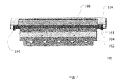
- the assembled apparatus 100 is shown in Fig. 2 . It should be noted that, for the convenience of showing the structure of the apparatus 100, the sections of the components are also illustratively shown in Fig. 2 .
- Fig. 3 shows the apparatus 100 and the lighting device contained therein.
- the glass plate 103 serves as a light outlet.
- the light outlet may be provided in other manners.
- the housing bottom 102 and the housing top 105 may be made of transparent material and serve as ta light outlet.
- the lighting device shown in Fig. 3 is a plurality of LEDs. Those ordinary skilled in the art should understand, the lighting device may be single or multiple lighting device of any proper type.
- the space for containing the lighting device may be isolated with the outside of the apparatus 100.
- it is usually difficult to totally isolate the inside of the apparatus 100 with the water environment only by means of above structure, or it is usually highly expensive, for example, by extremely high machining precision, to sufficiently isolate the inside of the apparatus 100 with the water environment.
- the apparatus 100 containing the lighting device and used for lighting from the water may be the size of 32 cm ⁇ 32cm, and it is difficult to manufacture the housing bottom 102 and the housing top 105 with such a size to be totally plat by the existing process.
- the housing bottom 102 and the housing top 105 may have deformation during transportation.
- the change of temperature will also influence the sealing among the housing bottom 102, the glass plate 103, the glass sealing 104 and the housing top 105 which are usually made of different material.
- the inside of the apparatus 100 may be filled with a medium such as air, and the pressure of the air inside the apparatus 100 is higher than the pressure of water wherein the apparatus 100 is arranged when operating.
- a medium such as air
- the pressure of the air inside the apparatus 100 is higher than the pressure of water wherein the apparatus 100 is arranged when operating.
- the apparatus may include a sensor 106 and a valve 107 as shown in Fig. 3 in order to keep the pressure of the air inside the apparatus 100 within a predetermined range.
- Fig. 3 shows the sensor 106 and the valve 107 of the apparatus 100.
- the sensor 106 detects the pressure of the air inside the apparatus 100.
- the sensor 106 may be a digital or analog gas gauge, and may also be any other type of means suitable for detecting the pressure of the air inside the apparatus 100.
- the sensor 106 may be corresponding type of means for detecting the pressure of such medium.
- Fig. 3 shows that the sensor 106 is located on the housing bottom 102, the sensor 106 may be located at any proper position.
- the valve 107 is located on the housing bottom 102, but the embodiment of the present disclosure is not limited thereto, and the valve 107 may be located on the housing top 105 or the glass plate 103, as long as the valve 107 is located on the closed housing of the apparatus 100.
- the pressure of the air may be changed via the valve 107 by an execution device (not shown), such that the pressure of the air is kept within the predetermined range.
- the execution device may be any device suitable for changing the pressure of the air, such as a pump.
- the execution device may be corresponding type of means for changing the pressure of such medium.
- the execution device may be either a separated device outside the apparatus 100, or a component of the apparatus 100.
- the communication between the sensor 106 and the execution device may be performed by means of remote control such as RDM (Remote Device Management)/DMX (Digital Multiplex).
- RDM Remote Device Management
- DMX Digital Multiplex
- the RDM/DMX remote control may also be used for control the lighting device, particularly an LED, contained in the apparatus 100.
- the lighting device may further have RDM/DMX receiver for receiving signals from an RDM/DMX controller, a circuit for diming via the RDM/DMX controller, a circuit for LED over-heat protection, a circuit for LED temperature monitor, a circuit for output short-circuit protection, a circuit for providing constant current for each LED and the like.
- the lighting device may have the specification as following: 20-30 DC power input, 8 bit PWM precision for each channel, 1.4A constant current for each LED which could go up to 2A if necessary.
- the communication between the sensor 106 and the execution device may also be performed in any other proper manner.
- the valve 107 may be a single way valve 107.
- the execution device increases the pressure of the air via the single way valve 107.
- the pressure of the air inside the apparatus 100 it is also possible to require the pressure of the air inside the apparatus 100 to be below a predetermined upper limit.
- another single way valve (not shown) may be provided.
- the execution device decreases the pressure of the air via the other single way valve.
- the valve 107 may be configured as a two way valve.
- the execution device increases the pressure of the air via the two way valve, and when the pressure of the air detected by the sensor 106 is higher than the predetermined upper limit, the execution device decreases the pressure of the air via the two way valve.
- a valve for changing the pressure of the air inside the apparatus 100 is provided on the closed housing of the apparatus 100.
- the valve may be a single way valve.
Landscapes
- Engineering & Computer Science (AREA)
- General Engineering & Computer Science (AREA)
- Physics & Mathematics (AREA)
- Mechanical Engineering (AREA)
- Microelectronics & Electronic Packaging (AREA)
- Optics & Photonics (AREA)
- Arrangement Of Elements, Cooling, Sealing, Or The Like Of Lighting Devices (AREA)
- Fluid Mechanics (AREA)
- General Physics & Mathematics (AREA)
- Automation & Control Theory (AREA)
- Physical Or Chemical Processes And Apparatus (AREA)
- Pressure Vessels And Lids Thereof (AREA)
Abstract
Description
- The present disclosure relates to isolation of apparatus, and more specifically, to an apparatus with a closed housing, as well as isolation and manufacture method thereof.
- In the applications such as watersceen film, water-screen laser show, digital water curtain and the like, lighting device or other devices which operate under water are usually necessary. Such devices under water are usually arranged in an isolation apparatus with a closed housing so as to isolate the devices with the water environment surround them. However, due to the manufacture error of the housing and the like, it is usually difficult to totally isolate the inside of the isolation apparatus with the water environment only by means of the housing, or it is usually highly expensive to sufficiently isolate the inside of the isolation apparatus with the water environment.
- Once the water gets into the housing, the performance and/or lifetime of the devices, such as lighting devices, contained in the isolation apparatus will be influenced.
- Besides, even if the inside of the isolation apparatus is sufficiently isolated with the water environment in an expensive manner, it is usually difficult to maintain or replace the isolation apparatus itself or the devices contained therein.
- Therefore, the present disclosure proposes an apparatus with a closed housing, as well as isolation and manufacture method thereof, in order to isolate the inside of the apparatus with a first medium outside the apparatus.
- According to an embodiment of the present utility model, it is provided an apparatus with a closed housing, wherein the apparatus is arranged in a first medium during operating, and the inside of the apparatus is filled with a second medium the pressure of which is higher than the pressure of the first medium.
- The apparatus may comprise: a sensor configured to detect the pressure of the second medium; and a single way valve disposed on the closed housing configured such that when the pressure of the second medium detected by the sensor is lower than a predetermined threshold value, the pressure of the second medium is increased via the single way valve so as to keep the pressure of the second medium above the predetermined threshold value.
- Likely, the apparatus may comprise: a sensor configured to detect the pressure of the second medium; and a valve disposed on the closed housing configured such that when the pressure of the second medium detected by the sensor is beyond a predetermined range, the pressure of the second medium is changed via the valve so as to keep the pressure of the second medium within the predetermined range.
- In the apparatus, the first medium may be liquid, particularly water, and the second medium may be gas, particularly air.
- A lighting device, particularly an LED, may be contained in the apparatus, and a light outlet may be provided on the closed housing. Such apparatus may be used for lighting from the water.
- According to another embodiment of the present utility model, it is further provided a method for isolating the inside of an apparatus having a closed housing with a first medium outside the apparatus, comprising: filling the inside of the apparatus with a second medium such that the pressure of the second medium is higher than the pressure of the first medium.
- The method may further comprise: detecting the pressure of the second medium; and increasing the pressure of the second medium so as to keep the pressure of the second medium above a predetermined threshold value, when the pressure of the second medium is lower than the predetermined threshold value.
- Likely, the method may comprise: detecting the pressure of the second medium; and changing the pressure of the second medium so as to keep the pressure of the second medium within a predetermined range, when the pressure of the second medium is beyond the predetermined range.
- In the method, the first medium may be liquid, particularly water, and the second medium may be gas, particularly air.
- In the method, a lighting apparatus, particularly an LED, may be received in the apparatus, and a light outlet may be provided on the closed housing.
- According to another embodiment of the present utility model, it is further provided a method for manufacturing the apparatus described above, comprising: providing a valve on the closed housing for changing the pressure of the second medium inside the apparatus. The valve may be a single way valve.
- By means of the apparatus with the closed housing and the isolation and manufacture method according to the embodiments of the present disclosure, at least one of the following objects may be achieved: achieving sufficient sealing with relatively low cost, improving the performance and/or lifetime of the devices contained in the apparatus, and facilitate the maintaining and replacing of the apparatus and the devices contained therein.
- These and other advantages of the present disclosure will become more obvious hereinafter by means of the detailed illustration of the preferred embodiment of the invention in conjunction with drawings.
- The present disclosure will be better understood with reference to the following description given in conjunction with the drawings. In the drawings, the same or similar reference numerals indicate the same or similar components. The drawings and the following detailed description are included in the specification to form a part of the specification, and are used to further illustrate the preferred embodiments of the invention by means of some examples and explain the principles and advantages of the invention. In the drawings:
-
Figure 1 is an illustrative diagram showing some components of an apparatus with a closed housing according to an embodiment of the present disclosure; -
Figure 2 is an illustrative diagram showing the apparatus with the closed housing according to the embodiment of the present disclosure; and -
Figure 3 is an illustrative diagram showing the sensor and valve included in the apparatus with the closed housing according to the embodiment of the present disclosure. - The exemplary embodiments of the present disclosure are described hereinafter in conjunction with the drawings. For the sake of conciseness and clarity, not all the features of the actual embodiments are described in the specification.
- Herein, description of the embodiments of the present disclosure will be made by taking the
apparatus 100 with a closed housing and containing a lighting device as an example. - Those ordinary skilled in the art should understand, the device contained in the
apparatus 100 may be any type of device other than lighting device. - The
apparatus 100 is arranged in the water when operating, and the inside of theapparatus 100 is filled with air the pressure of which is higher the pressure of water. - Those ordinary skilled in the art should understand, the
apparatus 100 may be arranged in other proper liquid, such as oil and the like, when operating, and may also be arranged in medium other than liquid, such as gas which is corrosive to the device contained in theapparatus 100, when operating. Besides, the inside of theapparatus 100 may be filled with gas other than air, such as nitrogen or inert gas, and may also be filled with medium other than gas, such as liquid which is advantageous to, or at least not disadvantageous to, the device contained in theapparatus 100. -
Fig. 1 is an illustrative diagram showing some components of theapparatus 100. - In
Fig. 1 , theapparatus 100 mainly includesscrews 101, ahousing bottom 102, aglass plate 103, a glass sealing 104 and ahousing top 105. It should be noted that, for the convenience of showing the structure of theapparatus 100, the sections of the components are illustratively shown inFig. 1 . - Although only two
screws 101 are shown inFig. 1 , in fact, the amount of thescrews 101 are not limited thereto. Thehousing bottom 102 and thehousing top 105 are fixed together by means of thescrews 101, and theglass plate 103 is positioned between thehousing bottom 102 and thehousing top 105 by means of the glass sealing 104. The more detailed relationships of amounting among thescrews 101, thehousing bottom 102, theglass plate 103, the glass sealing 104 and thehousing top 105 are not the points of the present disclosure, and will not be described in detail herein. - The assembled
apparatus 100 is shown inFig. 2 . It should be noted that, for the convenience of showing the structure of theapparatus 100, the sections of the components are also illustratively shown inFig. 2 . -
Fig. 3 shows theapparatus 100 and the lighting device contained therein. InFig. 3 , theglass plate 103 serves as a light outlet. Those ordinary skilled in the art should understand, when theapparatus 100 contains a lighting device, the light outlet may be provided in other manners. For example, thehousing bottom 102 and thehousing top 105 may be made of transparent material and serve as ta light outlet. - Besides, it should be noted that, the lighting device shown in
Fig. 3 is a plurality of LEDs. Those ordinary skilled in the art should understand, the lighting device may be single or multiple lighting device of any proper type. - Due to the structure of the
apparatus 100 as shown inFigs. 1 and2 , the space for containing the lighting device may be isolated with the outside of theapparatus 100. However, due to the existence of manufacturing error and the like, it is usually difficult to totally isolate the inside of theapparatus 100 with the water environment only by means of above structure, or it is usually highly expensive, for example, by extremely high machining precision, to sufficiently isolate the inside of theapparatus 100 with the water environment. - For example, the
apparatus 100 containing the lighting device and used for lighting from the water may be the size of 32 cm × 32cm, and it is difficult to manufacture thehousing bottom 102 and thehousing top 105 with such a size to be totally plat by the existing process. Besides, thehousing bottom 102 and thehousing top 105 may have deformation during transportation. Furthermore, the change of temperature will also influence the sealing among thehousing bottom 102, theglass plate 103, the glass sealing 104 and thehousing top 105 which are usually made of different material. - According to the embodiment of the present disclosure, the inside of the
apparatus 100 may be filled with a medium such as air, and the pressure of the air inside theapparatus 100 is higher than the pressure of water wherein theapparatus 100 is arranged when operating. By means of such configuration, even if totally isolation of the inside of theapparatus 100 with the water environment cannot be achieved by the structure shown inFigs. 1 and2 , the water outside theapparatus 100 is still not able to get into the inside of theapparatus 100 due to the pressure of air. Therefore, it is possible to prevent the performance and/or lifetime of the device contained in theapparatus 100 from being influenced by the inducing of water or by the increasing of humidity caused by the inducing of water. Meanwhile, since theapparatus 100 does not have any complex structure, it will be easy to maintain or replace theapparatus 100 itself or the device inside theapparatus 100. - Since the pressure within the
apparatus 100 may change, for example, the air inside theapparatus 100 may slowly leaks into the water outside theapparatus 100 due to the imperfect isolation of the inside of theapparatus 100 with the water environment, the apparatus may include asensor 106 and avalve 107 as shown inFig. 3 in order to keep the pressure of the air inside theapparatus 100 within a predetermined range.Fig. 3 shows thesensor 106 and thevalve 107 of theapparatus 100. - The
sensor 106 detects the pressure of the air inside theapparatus 100. Thesensor 106 may be a digital or analog gas gauge, and may also be any other type of means suitable for detecting the pressure of the air inside theapparatus 100. Besides, when the medium inside theapparatus 100 is the medium other than air, thesensor 106 may be corresponding type of means for detecting the pressure of such medium. - Although
Fig. 3 shows that thesensor 106 is located on thehousing bottom 102, thesensor 106 may be located at any proper position. - The
valve 107 is located on thehousing bottom 102, but the embodiment of the present disclosure is not limited thereto, and thevalve 107 may be located on thehousing top 105 or theglass plate 103, as long as thevalve 107 is located on the closed housing of theapparatus 100. - When the
sensor 106 detects that the pressure of the air goes beyond the predetermined range, the pressure of the air may be changed via thevalve 107 by an execution device (not shown), such that the pressure of the air is kept within the predetermined range. - The execution device may be any device suitable for changing the pressure of the air, such as a pump. When the medium inside the
apparatus 100 is the medium other than air, the execution device may be corresponding type of means for changing the pressure of such medium. Besides, the execution device may be either a separated device outside theapparatus 100, or a component of theapparatus 100. - The communication between the
sensor 106 and the execution device may be performed by means of remote control such as RDM (Remote Device Management)/DMX (Digital Multiplex). In the application scene of lighting from water, the RDM/DMX remote control may also be used for control the lighting device, particularly an LED, contained in theapparatus 100. - Specifically, in the case that the lighting device is an LED, the lighting device may further have RDM/DMX receiver for receiving signals from an RDM/DMX controller, a circuit for diming via the RDM/DMX controller, a circuit for LED over-heat protection, a circuit for LED temperature monitor, a circuit for output short-circuit protection, a circuit for providing constant current for each LED and the like.
- In a specific application, the lighting device may have the specification as following: 20-30 DC power input, 8 bit PWM precision for each channel, 1.4A constant current for each LED which could go up to 2A if necessary.
- Since the configuration of the lighting device is not the point of the present disclosure, for the sake of simplicity, the detailed description thereof will not be made herein.
- Those ordinary skilled in the art should understand, the communication between the
sensor 106 and the execution device may also be performed in any other proper manner. - Usually, the pressure of the air inside the
apparatus 100 only needs to higher than a predetermined threshold value. At this time, thevalve 107 may be asingle way valve 107. When the pressure of the air detected by thesensor 106 is lower than the predetermined threshold value, the execution device increases the pressure of the air via thesingle way valve 107. - In some application scene, it is also possible to require the pressure of the air inside the
apparatus 100 to be below a predetermined upper limit. At this time, another single way valve (not shown) may be provided. When the pressure of the air detected by thesensor 106 is higher than the predetermined upper limit, the execution device decreases the pressure of the air via the other single way valve. - Besides, in the case that the pressure of the air inside the
apparatus 100 is required to be below a predetermined upper limit, thevalve 107 may be configured as a two way valve. When the pressure of the air detected by thesensor 106 is lower than the predetermined threshold value, the execution device increases the pressure of the air via the two way valve, and when the pressure of the air detected by thesensor 106 is higher than the predetermined upper limit, the execution device decreases the pressure of the air via the two way valve. - Base on above, according to the embodiment of the present disclosure, it is also provided a method for manufacturing the
apparatus 100, wherein, a valve for changing the pressure of the air inside theapparatus 100 is provided on the closed housing of theapparatus 100. The valve may be a single way valve. - The terms "include", "comprise" and any other variants of them are inclusive, and do not exclude additional, unrecited elements of a process, method, product, apparatus or device, as well as those elements that are inherently included by the process, method, product, apparatus or device. Without further limitations, the wording "including an" element does not exclude the possibility of the same elements present in the process, method, product, apparatus or device including the element.
- The embodiments of the present disclosure are described in detail in conjunction with the accompanying drawings. However, those ordinary skilled in the art will appreciate that the embodiments described above are for illustrative purposes only and shall not be interpreted as limiting the present disclosure. Those ordinary skilled in the art will also appreciate that various modifications, equivalents and variations may be made without deviation from the spirit and scope of the present disclosurel defined by the claims attached. Therefore, the scope of the present disclosure shall be defined by only the claims attached and their equivalents.
- Moreover, the scope of the present disclosure is not limited to the specific embodiments of the processes, methods, apparatuses and devices described herein. Those skilled in the art will appreciate that, based on the present utility model, the process, method, apparatus or device according to the present disclosure may use those elements, either existing or to be developed in the future, that carry out functions or can lead to results substantially the same as the elements disclosed in the embodiments herein. Therefore, the attached claims shall include the process, method, apparatus or device including such elements.
Claims (16)
- An apparatus with a closed housing, wherein the apparatus is arranged in a first medium during operating, and the inside of the apparatus is filled with a second medium the pressure of which is higher than the pressure of the first medium.
- The apparatus according to claim 1, comprising:a sensor configured to detect the pressure of the second medium; anda single way valve disposed on the closed housing configured such that when the pressure of the second medium detected by the sensor is lower than a predetermined threshold value, the pressure of the second medium is increased via the single way valve so as to keep the pressure of the second medium above the predetermined threshold value.
- The apparatus according to claim 1, comprising:a sensor configured to detect the pressure of the second medium; anda valve disposed on the closed housing configured such that when the pressure of the second medium detected by the sensor is beyond a predetermined range, the pressure of the second medium is changed via the valve so as to keep the pressure of the second medium within the predetermined range.
- The apparatus according to any one of claims 1 to 3, wherein:the first medium is liquid and the second medium is gas.
- The apparatus according to claim 4, wherein:the liquid is water and the gas is air.
- The apparatus according to any one of claims 1 to 5, wherein:a lighting device is received in the apparatus , anda light outlet is provided on the closed housing.
- The apparatus according to claim 6, wherein:the lighting device is an LED.
- A method for isolating the inside of an apparatus having a closed housing with a first medium outside the apparatus, comprising:filling the inside of the apparatus with a second medium such that the pressure of the second medium is higher than the pressure of the first medium.
- The method according to claim 8, further comprising:detecting the pressure of the second medium; andincreasing the pressure of the second medium so as to keep the pressure of the second medium above a predetermined threshold value, when the pressure of the second medium is lower than the predetermined threshold value.
- The method according to claim 8, further comprising:detecting the pressure of the second medium; andchanging the pressure of the second medium so as to keep the pressure of the second medium within a predetermined range, when the pressure of the second medium is beyond the predetermined range.
- The method according to any one of claims 8 to 10, wherein:the first medium is liquid and the second medium is gas.
- The method according to claim 11, wherein:the liquid is water and the gas is air.
- The method according to any one of claims 8 to 12, wherein:a lighting apparatus is received in the apparatus, anda light outlet is provided on the closed housing.
- The method according to claim 13, wherein:the lighting apparatus is an LED.
- A method for manufacturing the apparatus according to any one of claims 1 to 7, comprising:providing a valve on the closed housing for changing the pressure of the second medium inside the apparatus.
- The method according to claim 15, wherein:the valve is a single way valve.
Applications Claiming Priority (1)
| Application Number | Priority Date | Filing Date | Title |
|---|---|---|---|
| CN201310203191.7A CN104185397B (en) | 2013-05-28 | 2013-05-28 | Device and its isolation and manufacturing method with closing housing |
Publications (3)
| Publication Number | Publication Date |
|---|---|
| EP2808604A2 true EP2808604A2 (en) | 2014-12-03 |
| EP2808604A3 EP2808604A3 (en) | 2014-12-17 |
| EP2808604B1 EP2808604B1 (en) | 2017-05-10 |
Family
ID=50735968
Family Applications (1)
| Application Number | Title | Priority Date | Filing Date |
|---|---|---|---|
| EP14169275.6A Not-in-force EP2808604B1 (en) | 2013-05-28 | 2014-05-21 | Apparatus with closed housing and the isolation and manufacture method thereof |
Country Status (3)
| Country | Link |
|---|---|
| US (1) | US20140355253A1 (en) |
| EP (1) | EP2808604B1 (en) |
| CN (1) | CN104185397B (en) |
Cited By (1)
| Publication number | Priority date | Publication date | Assignee | Title |
|---|---|---|---|---|
| WO2025227456A1 (en) * | 2024-04-29 | 2025-11-06 | Guangzhou Haoyang Electronic Co., Ltd | Light fixture with self-test ability of sealing |
Families Citing this family (4)
| Publication number | Priority date | Publication date | Assignee | Title |
|---|---|---|---|---|
| CN105525576A (en) * | 2015-12-28 | 2016-04-27 | 江阴皇润车业有限公司 | Parking sign device |
| US9857066B2 (en) | 2015-12-28 | 2018-01-02 | Ephesus Lighting, Inc. | LED illumination device with single pressure cavity |
| CN114353033A (en) * | 2022-01-14 | 2022-04-15 | 江西依泰思防爆科技有限公司 | An LED explosion-proof lamp with a pressure quick adjustment mechanism |
| CN115379698A (en) * | 2022-07-29 | 2022-11-22 | 荣成歌尔微电子有限公司 | Package and electronic device |
Family Cites Families (7)
| Publication number | Priority date | Publication date | Assignee | Title |
|---|---|---|---|---|
| GB396089A (en) * | 1932-01-20 | 1933-07-20 | Samuel Alexander Pollock | Improvements in or relating to electric safety-lamps |
| US3565111A (en) * | 1969-02-20 | 1971-02-23 | Swan A Pearson | Solenoid-actuated pilot valve |
| US5751095A (en) * | 1993-10-08 | 1998-05-12 | General Electric Company | Simulated reflector lamp using par lamp components |
| US6633110B2 (en) * | 1994-03-22 | 2003-10-14 | Tailored Lighting Inc. | Underwater lamp |
| CA2633214A1 (en) * | 2007-06-05 | 2008-12-05 | Bioled Ltda | Submergible lamp for use in aquaculture |
| CN100580305C (en) * | 2007-07-12 | 2010-01-13 | 徐焕恩 | Safe and low-consumption intelligent gas supply system for gas storage cylinders |
| US8444283B1 (en) * | 2012-10-18 | 2013-05-21 | Steven Miller | Systems and methods for underwater lighting |
-
2013
- 2013-05-28 CN CN201310203191.7A patent/CN104185397B/en not_active Expired - Fee Related
-
2014
- 2014-05-21 EP EP14169275.6A patent/EP2808604B1/en not_active Not-in-force
- 2014-05-22 US US14/285,558 patent/US20140355253A1/en not_active Abandoned
Non-Patent Citations (1)
| Title |
|---|
| None |
Cited By (1)
| Publication number | Priority date | Publication date | Assignee | Title |
|---|---|---|---|---|
| WO2025227456A1 (en) * | 2024-04-29 | 2025-11-06 | Guangzhou Haoyang Electronic Co., Ltd | Light fixture with self-test ability of sealing |
Also Published As
| Publication number | Publication date |
|---|---|
| CN104185397A (en) | 2014-12-03 |
| EP2808604A3 (en) | 2014-12-17 |
| US20140355253A1 (en) | 2014-12-04 |
| EP2808604B1 (en) | 2017-05-10 |
| CN104185397B (en) | 2018-07-10 |
Similar Documents
| Publication | Publication Date | Title |
|---|---|---|
| EP2808604B1 (en) | Apparatus with closed housing and the isolation and manufacture method thereof | |
| US10278247B2 (en) | System and method for controlling operation of an LED-based light | |
| EP2745040B1 (en) | Modular lighting system | |
| US9510400B2 (en) | User input systems for an LED-based light | |
| US11300257B2 (en) | LED lighting fixture | |
| WO2013112861A3 (en) | Iintegrated circuit element and electronic circuit for light emitting diode applications, having thermistor for forward voltage drop temperature compensation | |
| EP3290780A3 (en) | Lamp assembly for vehicle comprising a plurality of oled modules | |
| FI20185043A1 (en) | Service platform, container handling carrier and method | |
| CN103718648A (en) | LED light source with reduced flicker | |
| Lall et al. | Reliability and failure modes of solid-state lighting electrical drivers subjected to accelerated aging | |
| KR20170087463A (en) | Lighting apparatus for hazardous areas | |
| MY209143A (en) | Air purifier | |
| SG10201902344VA (en) | Heatsink for electrical circuitry | |
| US20160027710A1 (en) | Semiconductor module, semiconductor module package and semiconductor apparatus | |
| JP2016162695A (en) | Lighting device and correction method for the same | |
| WO2017001582A3 (en) | System for compensation of expansion/contraction of a cooling medium inside a sealed closure | |
| US9237625B1 (en) | Driver circuit with a common interface for negative temperature coefficient resistor and bi-metallic strip temperature sensing | |
| CN204254311U (en) | Lighting module, for the pedestal of lighting module and lighting device | |
| WO2013179215A3 (en) | Tunable lighting system | |
| US9528661B2 (en) | Lighting module for LED-based lighting | |
| US20150262491A1 (en) | Updating an airfield lighting system with an led light source | |
| US20170016789A1 (en) | Thermoelectric heating, cooling and power generation for direct mount and dual compartment fill remote seal systems | |
| CN114981851A (en) | Sensor device and expansion module | |
| US9041272B2 (en) | Control of lumen loss in a liquid-filled LED bulb | |
| JP6025093B2 (en) | Light emitting diode lighting device, lighting fixture using the same, and vehicle lighting fixture |
Legal Events
| Date | Code | Title | Description |
|---|---|---|---|
| PUAL | Search report despatched |
Free format text: ORIGINAL CODE: 0009013 |
|
| PUAI | Public reference made under article 153(3) epc to a published international application that has entered the european phase |
Free format text: ORIGINAL CODE: 0009012 |
|
| 17P | Request for examination filed |
Effective date: 20140521 |
|
| AK | Designated contracting states |
Kind code of ref document: A2 Designated state(s): AL AT BE BG CH CY CZ DE DK EE ES FI FR GB GR HR HU IE IS IT LI LT LU LV MC MK MT NL NO PL PT RO RS SE SI SK SM TR |
|
| AX | Request for extension of the european patent |
Extension state: BA ME |
|
| AK | Designated contracting states |
Kind code of ref document: A3 Designated state(s): AL AT BE BG CH CY CZ DE DK EE ES FI FR GB GR HR HU IE IS IT LI LT LU LV MC MK MT NL NO PL PT RO RS SE SI SK SM TR |
|
| AX | Request for extension of the european patent |
Extension state: BA ME |
|
| RIC1 | Information provided on ipc code assigned before grant |
Ipc: F21Y 101/02 20060101ALN20141110BHEP Ipc: F21V 31/03 20060101AFI20141110BHEP |
|
| R17P | Request for examination filed (corrected) |
Effective date: 20150617 |
|
| RBV | Designated contracting states (corrected) |
Designated state(s): AL AT BE BG CH CY CZ DE DK EE ES FI FR GB GR HR HU IE IS IT LI LT LU LV MC MK MT NL NO PL PT RO RS SE SI SK SM TR |
|
| 17Q | First examination report despatched |
Effective date: 20160211 |
|
| GRAP | Despatch of communication of intention to grant a patent |
Free format text: ORIGINAL CODE: EPIDOSNIGR1 |
|
| RIC1 | Information provided on ipc code assigned before grant |
Ipc: F21V 31/03 20060101AFI20161111BHEP Ipc: F21Y 115/10 20160101ALN20161111BHEP |
|
| INTG | Intention to grant announced |
Effective date: 20161215 |
|
| GRAS | Grant fee paid |
Free format text: ORIGINAL CODE: EPIDOSNIGR3 |
|
| GRAA | (expected) grant |
Free format text: ORIGINAL CODE: 0009210 |
|
| AK | Designated contracting states |
Kind code of ref document: B1 Designated state(s): AL AT BE BG CH CY CZ DE DK EE ES FI FR GB GR HR HU IE IS IT LI LT LU LV MC MK MT NL NO PL PT RO RS SE SI SK SM TR |
|
| REG | Reference to a national code |
Ref country code: GB Ref legal event code: FG4D |
|
| REG | Reference to a national code |
Ref country code: AT Ref legal event code: REF Ref document number: 892753 Country of ref document: AT Kind code of ref document: T Effective date: 20170515 Ref country code: CH Ref legal event code: EP |
|
| REG | Reference to a national code |
Ref country code: FR Ref legal event code: PLFP Year of fee payment: 4 |
|
| REG | Reference to a national code |
Ref country code: IE Ref legal event code: FG4D |
|
| REG | Reference to a national code |
Ref country code: DE Ref legal event code: R096 Ref document number: 602014009569 Country of ref document: DE |
|
| REG | Reference to a national code |
Ref country code: NL Ref legal event code: MP Effective date: 20170510 |
|
| REG | Reference to a national code |
Ref country code: LT Ref legal event code: MG4D |
|
| REG | Reference to a national code |
Ref country code: AT Ref legal event code: MK05 Ref document number: 892753 Country of ref document: AT Kind code of ref document: T Effective date: 20170510 |
|
| PG25 | Lapsed in a contracting state [announced via postgrant information from national office to epo] |
Ref country code: FI Free format text: LAPSE BECAUSE OF FAILURE TO SUBMIT A TRANSLATION OF THE DESCRIPTION OR TO PAY THE FEE WITHIN THE PRESCRIBED TIME-LIMIT Effective date: 20170510 Ref country code: NO Free format text: LAPSE BECAUSE OF FAILURE TO SUBMIT A TRANSLATION OF THE DESCRIPTION OR TO PAY THE FEE WITHIN THE PRESCRIBED TIME-LIMIT Effective date: 20170810 Ref country code: ES Free format text: LAPSE BECAUSE OF FAILURE TO SUBMIT A TRANSLATION OF THE DESCRIPTION OR TO PAY THE FEE WITHIN THE PRESCRIBED TIME-LIMIT Effective date: 20170510 Ref country code: HR Free format text: LAPSE BECAUSE OF FAILURE TO SUBMIT A TRANSLATION OF THE DESCRIPTION OR TO PAY THE FEE WITHIN THE PRESCRIBED TIME-LIMIT Effective date: 20170510 Ref country code: GR Free format text: LAPSE BECAUSE OF FAILURE TO SUBMIT A TRANSLATION OF THE DESCRIPTION OR TO PAY THE FEE WITHIN THE PRESCRIBED TIME-LIMIT Effective date: 20170811 Ref country code: AT Free format text: LAPSE BECAUSE OF FAILURE TO SUBMIT A TRANSLATION OF THE DESCRIPTION OR TO PAY THE FEE WITHIN THE PRESCRIBED TIME-LIMIT Effective date: 20170510 Ref country code: LT Free format text: LAPSE BECAUSE OF FAILURE TO SUBMIT A TRANSLATION OF THE DESCRIPTION OR TO PAY THE FEE WITHIN THE PRESCRIBED TIME-LIMIT Effective date: 20170510 |
|
| PG25 | Lapsed in a contracting state [announced via postgrant information from national office to epo] |
Ref country code: IS Free format text: LAPSE BECAUSE OF FAILURE TO SUBMIT A TRANSLATION OF THE DESCRIPTION OR TO PAY THE FEE WITHIN THE PRESCRIBED TIME-LIMIT Effective date: 20170910 Ref country code: SE Free format text: LAPSE BECAUSE OF FAILURE TO SUBMIT A TRANSLATION OF THE DESCRIPTION OR TO PAY THE FEE WITHIN THE PRESCRIBED TIME-LIMIT Effective date: 20170510 Ref country code: BG Free format text: LAPSE BECAUSE OF FAILURE TO SUBMIT A TRANSLATION OF THE DESCRIPTION OR TO PAY THE FEE WITHIN THE PRESCRIBED TIME-LIMIT Effective date: 20170810 Ref country code: PL Free format text: LAPSE BECAUSE OF FAILURE TO SUBMIT A TRANSLATION OF THE DESCRIPTION OR TO PAY THE FEE WITHIN THE PRESCRIBED TIME-LIMIT Effective date: 20170510 Ref country code: NL Free format text: LAPSE BECAUSE OF FAILURE TO SUBMIT A TRANSLATION OF THE DESCRIPTION OR TO PAY THE FEE WITHIN THE PRESCRIBED TIME-LIMIT Effective date: 20170510 Ref country code: RS Free format text: LAPSE BECAUSE OF FAILURE TO SUBMIT A TRANSLATION OF THE DESCRIPTION OR TO PAY THE FEE WITHIN THE PRESCRIBED TIME-LIMIT Effective date: 20170510 Ref country code: LV Free format text: LAPSE BECAUSE OF FAILURE TO SUBMIT A TRANSLATION OF THE DESCRIPTION OR TO PAY THE FEE WITHIN THE PRESCRIBED TIME-LIMIT Effective date: 20170510 |
|
| REG | Reference to a national code |
Ref country code: CH Ref legal event code: PL |
|
| PG25 | Lapsed in a contracting state [announced via postgrant information from national office to epo] |
Ref country code: SK Free format text: LAPSE BECAUSE OF FAILURE TO SUBMIT A TRANSLATION OF THE DESCRIPTION OR TO PAY THE FEE WITHIN THE PRESCRIBED TIME-LIMIT Effective date: 20170510 Ref country code: RO Free format text: LAPSE BECAUSE OF FAILURE TO SUBMIT A TRANSLATION OF THE DESCRIPTION OR TO PAY THE FEE WITHIN THE PRESCRIBED TIME-LIMIT Effective date: 20170510 Ref country code: EE Free format text: LAPSE BECAUSE OF FAILURE TO SUBMIT A TRANSLATION OF THE DESCRIPTION OR TO PAY THE FEE WITHIN THE PRESCRIBED TIME-LIMIT Effective date: 20170510 Ref country code: CZ Free format text: LAPSE BECAUSE OF FAILURE TO SUBMIT A TRANSLATION OF THE DESCRIPTION OR TO PAY THE FEE WITHIN THE PRESCRIBED TIME-LIMIT Effective date: 20170510 Ref country code: DK Free format text: LAPSE BECAUSE OF FAILURE TO SUBMIT A TRANSLATION OF THE DESCRIPTION OR TO PAY THE FEE WITHIN THE PRESCRIBED TIME-LIMIT Effective date: 20170510 |
|
| REG | Reference to a national code |
Ref country code: DE Ref legal event code: R097 Ref document number: 602014009569 Country of ref document: DE |
|
| REG | Reference to a national code |
Ref country code: IE Ref legal event code: MM4A |
|
| PG25 | Lapsed in a contracting state [announced via postgrant information from national office to epo] |
Ref country code: LI Free format text: LAPSE BECAUSE OF NON-PAYMENT OF DUE FEES Effective date: 20170531 Ref country code: IT Free format text: LAPSE BECAUSE OF FAILURE TO SUBMIT A TRANSLATION OF THE DESCRIPTION OR TO PAY THE FEE WITHIN THE PRESCRIBED TIME-LIMIT Effective date: 20170510 Ref country code: CH Free format text: LAPSE BECAUSE OF NON-PAYMENT OF DUE FEES Effective date: 20170531 Ref country code: SM Free format text: LAPSE BECAUSE OF FAILURE TO SUBMIT A TRANSLATION OF THE DESCRIPTION OR TO PAY THE FEE WITHIN THE PRESCRIBED TIME-LIMIT Effective date: 20170510 |
|
| PLBE | No opposition filed within time limit |
Free format text: ORIGINAL CODE: 0009261 |
|
| STAA | Information on the status of an ep patent application or granted ep patent |
Free format text: STATUS: NO OPPOSITION FILED WITHIN TIME LIMIT |
|
| PG25 | Lapsed in a contracting state [announced via postgrant information from national office to epo] |
Ref country code: LU Free format text: LAPSE BECAUSE OF NON-PAYMENT OF DUE FEES Effective date: 20170521 |
|
| 26N | No opposition filed |
Effective date: 20180213 |
|
| REG | Reference to a national code |
Ref country code: BE Ref legal event code: MM Effective date: 20170531 |
|
| PG25 | Lapsed in a contracting state [announced via postgrant information from national office to epo] |
Ref country code: IE Free format text: LAPSE BECAUSE OF NON-PAYMENT OF DUE FEES Effective date: 20170521 |
|
| REG | Reference to a national code |
Ref country code: FR Ref legal event code: PLFP Year of fee payment: 5 |
|
| PG25 | Lapsed in a contracting state [announced via postgrant information from national office to epo] |
Ref country code: SI Free format text: LAPSE BECAUSE OF FAILURE TO SUBMIT A TRANSLATION OF THE DESCRIPTION OR TO PAY THE FEE WITHIN THE PRESCRIBED TIME-LIMIT Effective date: 20170510 |
|
| PG25 | Lapsed in a contracting state [announced via postgrant information from national office to epo] |
Ref country code: BE Free format text: LAPSE BECAUSE OF NON-PAYMENT OF DUE FEES Effective date: 20170531 |
|
| PG25 | Lapsed in a contracting state [announced via postgrant information from national office to epo] |
Ref country code: MT Free format text: LAPSE BECAUSE OF NON-PAYMENT OF DUE FEES Effective date: 20170521 |
|
| GBPC | Gb: european patent ceased through non-payment of renewal fee |
Effective date: 20180521 |
|
| PG25 | Lapsed in a contracting state [announced via postgrant information from national office to epo] |
Ref country code: GB Free format text: LAPSE BECAUSE OF NON-PAYMENT OF DUE FEES Effective date: 20180521 |
|
| PG25 | Lapsed in a contracting state [announced via postgrant information from national office to epo] |
Ref country code: HU Free format text: LAPSE BECAUSE OF FAILURE TO SUBMIT A TRANSLATION OF THE DESCRIPTION OR TO PAY THE FEE WITHIN THE PRESCRIBED TIME-LIMIT; INVALID AB INITIO Effective date: 20140521 Ref country code: MC Free format text: LAPSE BECAUSE OF FAILURE TO SUBMIT A TRANSLATION OF THE DESCRIPTION OR TO PAY THE FEE WITHIN THE PRESCRIBED TIME-LIMIT Effective date: 20170510 |
|
| PG25 | Lapsed in a contracting state [announced via postgrant information from national office to epo] |
Ref country code: CY Free format text: LAPSE BECAUSE OF FAILURE TO SUBMIT A TRANSLATION OF THE DESCRIPTION OR TO PAY THE FEE WITHIN THE PRESCRIBED TIME-LIMIT Effective date: 20170510 |
|
| PG25 | Lapsed in a contracting state [announced via postgrant information from national office to epo] |
Ref country code: MK Free format text: LAPSE BECAUSE OF FAILURE TO SUBMIT A TRANSLATION OF THE DESCRIPTION OR TO PAY THE FEE WITHIN THE PRESCRIBED TIME-LIMIT Effective date: 20170510 |
|
| PG25 | Lapsed in a contracting state [announced via postgrant information from national office to epo] |
Ref country code: TR Free format text: LAPSE BECAUSE OF FAILURE TO SUBMIT A TRANSLATION OF THE DESCRIPTION OR TO PAY THE FEE WITHIN THE PRESCRIBED TIME-LIMIT Effective date: 20170510 |
|
| PG25 | Lapsed in a contracting state [announced via postgrant information from national office to epo] |
Ref country code: PT Free format text: LAPSE BECAUSE OF FAILURE TO SUBMIT A TRANSLATION OF THE DESCRIPTION OR TO PAY THE FEE WITHIN THE PRESCRIBED TIME-LIMIT Effective date: 20170510 |
|
| PG25 | Lapsed in a contracting state [announced via postgrant information from national office to epo] |
Ref country code: AL Free format text: LAPSE BECAUSE OF FAILURE TO SUBMIT A TRANSLATION OF THE DESCRIPTION OR TO PAY THE FEE WITHIN THE PRESCRIBED TIME-LIMIT Effective date: 20170510 |
|
| PGFP | Annual fee paid to national office [announced via postgrant information from national office to epo] |
Ref country code: FR Payment date: 20220523 Year of fee payment: 9 Ref country code: DE Payment date: 20220519 Year of fee payment: 9 |
|
| P01 | Opt-out of the competence of the unified patent court (upc) registered |
Effective date: 20230821 |
|
| REG | Reference to a national code |
Ref country code: DE Ref legal event code: R119 Ref document number: 602014009569 Country of ref document: DE |
|
| PG25 | Lapsed in a contracting state [announced via postgrant information from national office to epo] |
Ref country code: DE Free format text: LAPSE BECAUSE OF NON-PAYMENT OF DUE FEES Effective date: 20231201 |
|
| PG25 | Lapsed in a contracting state [announced via postgrant information from national office to epo] |
Ref country code: FR Free format text: LAPSE BECAUSE OF NON-PAYMENT OF DUE FEES Effective date: 20230531 |