EP2808483A2 - Packoff for liner deployment assembly - Google Patents
Packoff for liner deployment assembly Download PDFInfo
- Publication number
- EP2808483A2 EP2808483A2 EP14169639.3A EP14169639A EP2808483A2 EP 2808483 A2 EP2808483 A2 EP 2808483A2 EP 14169639 A EP14169639 A EP 14169639A EP 2808483 A2 EP2808483 A2 EP 2808483A2
- Authority
- EP
- European Patent Office
- Prior art keywords
- packoff
- string
- liner
- liner string
- lda
- Prior art date
- Legal status (The legal status is an assumption and is not a legal conclusion. Google has not performed a legal analysis and makes no representation as to the accuracy of the status listed.)
- Granted
Links
Images



Classifications
-
- E—FIXED CONSTRUCTIONS
- E21—EARTH OR ROCK DRILLING; MINING
- E21B—EARTH OR ROCK DRILLING; OBTAINING OIL, GAS, WATER, SOLUBLE OR MELTABLE MATERIALS OR A SLURRY OF MINERALS FROM WELLS
- E21B23/00—Apparatus for displacing, setting, locking, releasing or removing tools, packers or the like in boreholes or wells
- E21B23/06—Apparatus for displacing, setting, locking, releasing or removing tools, packers or the like in boreholes or wells for setting packers
-
- E—FIXED CONSTRUCTIONS
- E21—EARTH OR ROCK DRILLING; MINING
- E21B—EARTH OR ROCK DRILLING; OBTAINING OIL, GAS, WATER, SOLUBLE OR MELTABLE MATERIALS OR A SLURRY OF MINERALS FROM WELLS
- E21B23/00—Apparatus for displacing, setting, locking, releasing or removing tools, packers or the like in boreholes or wells
-
- E—FIXED CONSTRUCTIONS
- E21—EARTH OR ROCK DRILLING; MINING
- E21B—EARTH OR ROCK DRILLING; OBTAINING OIL, GAS, WATER, SOLUBLE OR MELTABLE MATERIALS OR A SLURRY OF MINERALS FROM WELLS
- E21B23/00—Apparatus for displacing, setting, locking, releasing or removing tools, packers or the like in boreholes or wells
- E21B23/02—Apparatus for displacing, setting, locking, releasing or removing tools, packers or the like in boreholes or wells for locking the tools or the like in landing nipples or in recesses between adjacent sections of tubing
-
- E—FIXED CONSTRUCTIONS
- E21—EARTH OR ROCK DRILLING; MINING
- E21B—EARTH OR ROCK DRILLING; OBTAINING OIL, GAS, WATER, SOLUBLE OR MELTABLE MATERIALS OR A SLURRY OF MINERALS FROM WELLS
- E21B33/00—Sealing or packing boreholes or wells
- E21B33/10—Sealing or packing boreholes or wells in the borehole
- E21B33/13—Methods or devices for cementing, for plugging holes, crevices or the like
-
- E—FIXED CONSTRUCTIONS
- E21—EARTH OR ROCK DRILLING; MINING
- E21B—EARTH OR ROCK DRILLING; OBTAINING OIL, GAS, WATER, SOLUBLE OR MELTABLE MATERIALS OR A SLURRY OF MINERALS FROM WELLS
- E21B43/00—Methods or apparatus for obtaining oil, gas, water, soluble or meltable materials or a slurry of minerals from wells
- E21B43/02—Subsoil filtering
- E21B43/10—Setting of casings, screens, liners or the like in wells
Definitions
- the present disclosure generally relates to a packoff for a liner deployment assembly.
- a wellbore is formed to access hydrocarbon bearing formations, e.g. crude oil and/or natural gas, by the use of drilling. Drilling is accomplished by utilizing a drill bit that is mounted on the end of a tubular string, such as a drill string. To drill within the wellbore to a predetermined depth, the drill string is often rotated by a top drive or rotary table on a surface platform or rig, and/or by a downhole motor mounted towards the lower end of the drill string. After drilling to a predetermined depth, the drill string and drill bit are removed and a section of casing is lowered into the wellbore. An annulus is thus formed between the string of casing and the formation.
- the casing string is cemented into the wellbore by circulating cement into the annulus defined between the outer wall of the casing and the borehole.
- the combination of cement and casing strengthens the wellbore and facilitates the isolation of certain areas of the formation behind the casing for the production of hydrocarbons.
- the well is drilled to a first designated depth with a drill bit on a drill string.
- the drill string is removed.
- a first string of casing is then run into the wellbore and set in the drilled out portion of the wellbore, and cement is circulated into the annulus behind the casing string.
- the well is drilled to a second designated depth, and a second string of casing or liner, is run into the drilled out portion of the wellbore. If the second string is a liner string, the liner is set at a depth such that the upper portion of the second string of casing overlaps the lower portion of the first string of casing.
- the liner string may then be hung off of the existing casing.
- the second casing or liner string is then cemented. This process is typically repeated with additional casing or liner strings until the well has been drilled to total depth. In this manner, wells are typically formed with two or more strings of casing/liner of an ever-decreasing diameter.
- a packoff for hanging a liner string from a tubular string cemented in a wellbore includes:
- the MODU 1 m may carry the drilling rig 1r and the fluid handling system 1h aboard and may include a moon pool, through which drilling operations are conducted.
- the semi-submersible MODU 1 m may include a lower barge hull which floats below a surface (aka waterline) 2s of sea 2 and is, therefore, less subject to surface wave action. Stability columns (only one shown) may be mounted on the lower barge hull for supporting an upper hull above the waterline.
- the upper hull may have one or more decks for carrying the drilling rig 1r and fluid handling system 1h.
- the MODU 1m may further have a dynamic positioning system (DPS) (not shown) or be moored for maintaining the moon pool in position over a subsea wellhead 10.
- DPS dynamic positioning system
- the drilling rig 1r may include a derrick 3, a floor 4, a top drive 5, an isolation valve 6, a cementing swivel 7, and a hoist.
- the top drive 5 may include a motor for rotating 8 the workstring 9.
- the top drive motor may be electric or hydraulic.
- a frame of the top drive 5 may be linked to a rail (not shown) of the derrick 3 for preventing rotation thereof during rotation of the workstring 9 and allowing for vertical movement of the top drive with a traveling block 11t of the hoist.
- the frame of the top drive 5 may be suspended from the derrick 3 by the traveling block 11t.
- the quill may be torsionally driven by the top drive motor and supported from the frame by bearings.
- the top drive may further have an inlet connected to the frame and in fluid communication with the quill.
- the traveling block 11t may be supported by wire rope 11 r connected at its upper end to a crown block 11c.
- the wire rope 11r may be woven through sheaves of the blocks 11 c,t and extend to drawworks 12 for reeling thereof, thereby raising or lowering the traveling block 11t relative to the derrick 3.
- the drilling rig 1r may further include a drill string compensator (not shown) to account for heave of the MODU 1 m.
- the drill string compensator may be disposed between the traveling block 11t and the top drive 5 (aka hook mounted) or between the crown block 11 c and the derrick 3 (aka top mounted).
- an upper end of the workstring 9 may be connected to the top drive quill, such as by threaded couplings.
- the workstring 9 may include a liner deployment assembly (LDA) 9d and a deployment string, such as joints of drill pipe 9p ( Figure 2A ) connected together, such as by threaded couplings.
- LDA liner deployment assembly
- An upper end of the LDA 9d may be connected a lower end of the drill pipe 9p, such as by a threaded connection.
- the LDA 9d may also be connected to a liner string 15.
- the liner string 15 may include a polished bore receptacle (PBR) 15r, a packer 15p, a liner hanger 15h, joints of liner 15j, a float collar 15c, and a reamer shoe 15s.
- the liner string members may each be connected together, such as by threaded couplings.
- the reamer shoe 15s may be rotated 8 by the top drive 5 via the workstring 9.
- the actuator swivel 7h may be similar to the cementing swivel 7c except that the housing inlet may be in fluid communication with a passage formed through the mandrel.
- the mandrel passage may extend to an outlet of the mandrel for connection to a hydraulic conduit for operating a hydraulic actuator of the launcher 7p.
- the actuator swivel 7h may be in fluid communication with a hydraulic power unit (HPU).
- HPU hydraulic power unit
- the canister may be tubular and have ribs formed along and around an outer surface thereof. Bypass passages may be formed between the ribs.
- the canister may further have a landing shoulder formed in a lower end thereof corresponding to the housing landing shoulder.
- the diverter may be operable to deflect fluid received from a cement line 14 away from a bore of the canister and toward the bypass passages.
- a cementing plug 43d may be disposed in the canister bore.
- the latch may include a body, a plunger, and a shaft.
- the body may be connected to a lug formed in an outer surface of the launcher housing, such as by a threaded connection.
- the plunger may be longitudinally movable relative to the body and radially movable relative to the housing between a capture position and a release position. The plunger may be moved between the positions by interaction, such as a jackscrew, with the shaft.
- the shaft may be longitudinally connected to and rotatable relative to the body.
- the actuator may be a hydraulic motor operable to rotate the shaft relative to the body.
- the PCA 1p may include a wellhead adapter 28b, one or more flow crosses 29u,m,b, one or more blow out preventers (BOPs) 30a,u,b, a lower marine riser package (LMRP) 16b, one or more accumulators, and a receiver 31.
- the LMRP 16b may include a control pod, a flex joint 32, and a connector 28u.
- the wellhead adapter 28b, flow crosses 29u,m,b, BOPs 30a,u,b, receiver 31, connector 28u, and flex joint 32 may each include a housing having a longitudinal bore therethrough and may each be connected, such as by flanges, such that a continuous bore is maintained therethrough.
- the flex joints 21, 32 may accommodate respective horizontal and/or rotational (aka pitch and roll) movement of the MODU 1 m relative to the riser 17 and the riser relative to the PCA 1 p.
- Each of the connector 28u and wellhead adapter 28b may include one or more fasteners, such as dogs, for fastening the LMRP 16b to the BOPs 30a,u,b and the PCA 1p to an external profile of the wellhead housing, respectively.
- Each of the connector 28u and wellhead adapter 28b may further include a seal sleeve for engaging an internal profile of the respective receiver 31 and wellhead housing.
- Each of the connector 28u and wellhead adapter 28b may be in electric or hydraulic communication with the control pod and/or further include an electric or hydraulic actuator and an interface, such as a hot stab, so that a remotely operated subsea vehicle (ROV) (not shown) may operate the actuator for engaging the dogs with the external profile.
- ROV remotely operated subsea vehicle
- the LMRP 16b may receive a lower end of the riser 17 and connect the riser to the PCA 1p.
- the control pod may be in electric, hydraulic, and/or optical communication with a rig controller (not shown) onboard the MODU 1m via an umbilical 33.
- the control pod may include one or more control valves (not shown) in communication with the BOPs 30a,u,b for operation thereof.
- Each control valve may include an electric or hydraulic actuator in communication with the umbilical 33.
- the umbilical 33 may include one or more hydraulic and/or electric control conduit/cables for the actuators.
- the accumulators may store pressurized hydraulic fluid for operating the BOPs 30a,u,b.
- a lower end of the booster line 18b may be connected to a branch of the flow cross 29u by a shutoff valve.
- a booster manifold may also connect to the booster line lower end and have a prong connected to a respective branch of each flow cross 29m,b.
- Shutoff valves may be disposed in respective prongs of the booster manifold.
- a separate kill line (not shown) may be connected to the branches of the flow crosses 29m,b instead of the booster manifold.
- An upper end of the booster line 18b may be connected to an outlet of a booster pump (not shown).
- a lower end of the choke line 18c may have prongs connected to respective second branches of the flow crosses 29m,b.
- Shutoff valves may be disposed in respective prongs of the choke line lower end.
- a lower end of a mud supply line may be connected to an outlet of the mud tank 35 and an upper end of the mud supply line may be connected to an inlet of the mud pump 34.
- An upper end of a cement supply line may be connected to an outlet of the cement mixer 42 and a lower end of the cement supply line may be connected to an inlet of the cement pump 13.
- the diverter valve 50 may include a housing, a bore valve, and a port valve.
- the diverter housing may include two or more tubular sections (three shown) connected to each other, such as by threaded couplings.
- the diverter housing may have threaded couplings formed at each longitudinal end thereof for connection to the drill pipe 9p at an upper end thereof and the junk bonnet 51 at a lower end thereof.
- the bore valve may be disposed in the housing.
- the bore valve may include a body and a valve member, such as a flapper, pivotally connected to the body and biased toward a closed position, such as by a torsion spring.
- the diverter port valve may include a sleeve and a biasing member, such as a compression spring.
- the sleeve may include two or more sections (four shown) connected to each other, such as by threaded couplings and/or fasteners.
- An upper section of the sleeve may be connected to a lower end of the bore valve body, such as by threaded couplings.
- Various interfaces between the sleeve and the housing and between the housing sections may be isolated by seals.
- the sleeve may be disposed in the housing and longitudinally movable relative thereto between an upper position (shown) and a lower position ( Figure 4A ).
- the piston may have a torsion profile formed in a lower end thereof and the valve shoulder may have a complementary torsion profile formed in an upper end thereof.
- the piston may further have reamer blades formed in an upper surface thereof.
- the torsion profiles may mate during removal of the LDA 9d from the liner string 15, thereby torsionally connecting the piston to the mandrel.
- the piston may then be rotated during removal to back ream debris accumulated adjacent an upper end of the PBR 15r.
- the piston lower end may also seat on the valve sleeve during removal. Should the bypass groove be clogged, pulling of the drill pipe 9p may cause the valve sleeve to be pushed downward relative to the mandrel and against the springs to open the radial ports, thereby releasing the hydraulic lock.
- the setting tool 52 may include a body, a plurality of fasteners, such as dogs, and a rotor. Although shown as one piece, the body may include two or more sections connected to each other, such as by threaded couplings and/or fasteners.
- the body may have threaded couplings formed at each longitudinal end thereof for connection to the junk bonnet 51 at an upper end thereof and the running tool 53 at a lower end thereof.
- the body may have a recess formed in an outer surface thereof for receiving the rotor.
- the rotor may include a thrust ring, a thrust bearing, and a guide ring. The guide ring and thrust bearing may be disposed in the recess.
- the lock sleeve may have an upper portion disposed along an outer surface of the body and extending into the piston lower portion and an enlarged lower portion.
- the lock sleeve may have one or more openings formed therethrough and spaced around the sleeve to receive a respective dog therein. Each dog may extend into a groove formed in an outer surface of the body, thereby fastening the lock sleeve to the body.
- a thrust bearing may be disposed in the lock sleeve lower portion and against a shoulder formed in an outer surface of the body. The thrust bearing may be biased against the body shoulder by a compression spring.
- Each lip may be energized to seal against an inner surface of the packer 15p, thereby isolating a pressure differential between the LDA bore/actuation chamber 71 and the buffer chamber 61, and each pair of garter springs 65o may support the respective seal lip to resist disengagement thereof.
- Cement slurry (not shown) may be pumped from the mixer 42 into the cementing swivel 7c via the valve 41 by the cement pump 13.
- the cement slurry may flow into the launcher 7p and be diverted past the dart 43d via the diverter and bypass passages.
- the flowback actuator may include two or more piston and cylinder assemblies (P&Cs), an upper swivel, and a lower swivel.
- P&Cs piston and cylinder assemblies
- Each P&C may be longitudinally coupled to the housing via the upper swivel and longitudinally coupled to the nose via the lower swivel.
- the upper swivel may include arms for engaging bails of a link-tilt (not shown), thereby torsionally coupling the P&Cs to the bails.
- Each of the swivels may include one or more bearings, thereby allowing relative rotation between the P&Cs and the housing.
- Hydraulic conduits may extend from each of the P&Cs to the top drive manifold to provide for extension and retraction of the P&Cs.
- a hydraulic conduit may also extend to the lower swivel which may be in fluid communication with the nose via a port thereof.
- the workstring may be advanced into the wellbore 24.
- Hydraulic fluid from the top drive manifold may be injected into the nose via the lower swivel, thereby locking the piston or moving the piston into the locked position and locking the piston. Hydraulic pressure may be maintained on the piston during advancement of the workstring 9 into the wellbore 24, thereby rigidly locking the piston and the dogs. Hydraulic fluid may be then injected into the P&Cs, thereby lowering the nose and the mandrel until an outer surface of the drill pipe box engages the seal and then the dogs.
Landscapes
- Geology (AREA)
- Life Sciences & Earth Sciences (AREA)
- Engineering & Computer Science (AREA)
- Mining & Mineral Resources (AREA)
- Environmental & Geological Engineering (AREA)
- Fluid Mechanics (AREA)
- Physics & Mathematics (AREA)
- General Life Sciences & Earth Sciences (AREA)
- Geochemistry & Mineralogy (AREA)
- Earth Drilling (AREA)
- Consolidation Of Soil By Introduction Of Solidifying Substances Into Soil (AREA)
- Details Of Rigid Or Semi-Rigid Containers (AREA)
- Package Frames And Binding Bands (AREA)
- Load-Engaging Elements For Cranes (AREA)
Abstract
Description
- The present disclosure generally relates to a packoff for a liner deployment assembly.
- A wellbore is formed to access hydrocarbon bearing formations, e.g. crude oil and/or natural gas, by the use of drilling. Drilling is accomplished by utilizing a drill bit that is mounted on the end of a tubular string, such as a drill string. To drill within the wellbore to a predetermined depth, the drill string is often rotated by a top drive or rotary table on a surface platform or rig, and/or by a downhole motor mounted towards the lower end of the drill string. After drilling to a predetermined depth, the drill string and drill bit are removed and a section of casing is lowered into the wellbore. An annulus is thus formed between the string of casing and the formation. The casing string is cemented into the wellbore by circulating cement into the annulus defined between the outer wall of the casing and the borehole. The combination of cement and casing strengthens the wellbore and facilitates the isolation of certain areas of the formation behind the casing for the production of hydrocarbons.
- It is common to employ more than one string of casing or liner in a wellbore. In this respect, the well is drilled to a first designated depth with a drill bit on a drill string. The drill string is removed. A first string of casing is then run into the wellbore and set in the drilled out portion of the wellbore, and cement is circulated into the annulus behind the casing string. Next, the well is drilled to a second designated depth, and a second string of casing or liner, is run into the drilled out portion of the wellbore. If the second string is a liner string, the liner is set at a depth such that the upper portion of the second string of casing overlaps the lower portion of the first string of casing. The liner string may then be hung off of the existing casing. The second casing or liner string is then cemented. This process is typically repeated with additional casing or liner strings until the well has been drilled to total depth. In this manner, wells are typically formed with two or more strings of casing/liner of an ever-decreasing diameter.
- In accordance with one aspect of the present invention there is provided a packoff for hanging a liner string from a tubular string cemented in a wellbore. The packoff includes:
- a tubular body having an outer groove and an inner groove; an inner seal assembly disposed in the inner groove; an outer seal assembly disposed in the outer groove; a cap connected to an upper end of the body for retaining the seal assemblies; a plurality of dogs disposed in respective openings formed through a wall of the body; and a lock sleeve. The lock sleeve is disposed in the body, longitudinally movable relative to the body, and has a cam profile formed in an outer surface thereof for extending the dogs.
- Further aspects and preferred features are set out in
claim 2 et seq. - So that the manner in which the above recited features of the present disclosure can be understood in detail, a more particular description of the disclosure, briefly summarized above, may be had by reference to embodiments, some of which are illustrated in the appended drawings. It is to be noted, however, that the appended drawings illustrate only typical embodiments of this disclosure and are therefore not to be considered limiting of its scope, for the disclosure may admit to other equally effective embodiments.
-
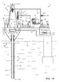
Figures 1A-1C illustrate a drilling system in a liner deployment mode, according to one embodiment of this disclosure. -
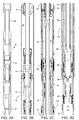
Figures 2A-2D illustrate a liner deployment assembly (LDA) of the drilling system. -
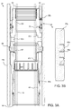
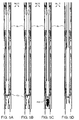
Figure 3A illustrates an upper packoff of the LDA in an engaged position.Figure 3B illustrates an outer seal assembly of the upper packoff.Figure 3C illustrates the upper packoff in a disengaged position. -
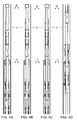
Figures 4A-4D illustrate operation of an upper portion of the LDA.Figures 5A-5D illustrate operation of a lower portion of the LDA. -
Figure 6 illustrates a flowback tool for use with the drilling system, according to another embodiment of this disclosure. -
Figures 1A-1C illustrate a drilling system in a liner deployment mode, according to one embodiment of this disclosure. Thedrilling system 1 may include a mobile offshore drilling unit (MODU) 1m, such as a semi-submersible, adrilling rig 1r, afluid handling system 1h, afluid transport system 1t, a pressure control assembly (PCA) 1p, and aworkstring 9. - The MODU 1 m may carry the
drilling rig 1r and thefluid handling system 1h aboard and may include a moon pool, through which drilling operations are conducted. Thesemi-submersible MODU 1 m may include a lower barge hull which floats below a surface (aka waterline) 2s ofsea 2 and is, therefore, less subject to surface wave action. Stability columns (only one shown) may be mounted on the lower barge hull for supporting an upper hull above the waterline. The upper hull may have one or more decks for carrying thedrilling rig 1r andfluid handling system 1h. TheMODU 1m may further have a dynamic positioning system (DPS) (not shown) or be moored for maintaining the moon pool in position over asubsea wellhead 10. - Alternatively, the MODU may be a drill ship. Alternatively, a fixed offshore drilling unit or a non-mobile floating offshore drilling unit may be used instead of the MODU. Alternatively, the wellbore may be subsea having a wellhead located adjacent to the waterline and the drilling rig may be a located on a platform adjacent the wellhead. Alternatively, the wellbore may be subterranean and the drilling rig located on a terrestrial pad.
- The
drilling rig 1r may include aderrick 3, a floor 4, atop drive 5, an isolation valve 6, acementing swivel 7, and a hoist. Thetop drive 5 may include a motor for rotating 8 theworkstring 9. The top drive motor may be electric or hydraulic. A frame of thetop drive 5 may be linked to a rail (not shown) of thederrick 3 for preventing rotation thereof during rotation of theworkstring 9 and allowing for vertical movement of the top drive with atraveling block 11t of the hoist. The frame of thetop drive 5 may be suspended from thederrick 3 by thetraveling block 11t. The quill may be torsionally driven by the top drive motor and supported from the frame by bearings. The top drive may further have an inlet connected to the frame and in fluid communication with the quill. The travelingblock 11t may be supported bywire rope 11 r connected at its upper end to acrown block 11c. Thewire rope 11r may be woven through sheaves of theblocks 11 c,t and extend todrawworks 12 for reeling thereof, thereby raising or lowering thetraveling block 11t relative to thederrick 3. Thedrilling rig 1r may further include a drill string compensator (not shown) to account for heave of theMODU 1 m. The drill string compensator may be disposed between thetraveling block 11t and the top drive 5 (aka hook mounted) or between thecrown block 11 c and the derrick 3 (aka top mounted). - Alternatively, a Kelly and rotary table may be used instead of the top drive.
- In the deployment mode, an upper end of the
workstring 9 may be connected to the top drive quill, such as by threaded couplings. Theworkstring 9 may include a liner deployment assembly (LDA) 9d and a deployment string, such as joints ofdrill pipe 9p (Figure 2A ) connected together, such as by threaded couplings. An upper end of the LDA 9d may be connected a lower end of thedrill pipe 9p, such as by a threaded connection. The LDA 9d may also be connected to aliner string 15. Theliner string 15 may include a polished bore receptacle (PBR) 15r, apacker 15p, aliner hanger 15h, joints ofliner 15j, afloat collar 15c, and areamer shoe 15s. The liner string members may each be connected together, such as by threaded couplings. Thereamer shoe 15s may be rotated 8 by thetop drive 5 via theworkstring 9. - Alternatively, the liner string may include a drillable drill bit (not shown) instead of the
reamer shoe 15s and theliner string 15 may be drilled into the lower formation, thereby extending the wellbore while deploying the liner string. - Once liner deployment has concluded, the isolation valve 6 may be connected to a quill of the
top drive 5 and an upper end of the cementinghead 7, such as by threaded couplings. An upper end of theworkstring 9 may be connected to a lower end of the cementinghead 7, such as by threaded couplings. The cementinghead 7 may include anactuator swivel 7h, a cementingswivel 7c, and one or more plug launchers 7p. The cementingswivel 7c may include a housing torsionally connected to thederrick 3, such as by bars, wire rope, or a bracket (not shown). The torsional connection may accommodate longitudinal movement of the cementingswivel 7c relative to thederrick 3. The cementingswivel 7c may further include a mandrel and bearings for supporting the housing from the mandrel while accommodatingrotation 8 of the mandrel. The mandrel may also be connected to the isolation valve 6. The cementingswivel 7c may further include an inlet formed through a wall of the housing and in fluid communication with a port formed through the mandrel and a seal assembly for isolating the inlet-port communication. The cementing mandrel port may provide fluid communication between a bore of the cementing head and the housing inlet. Each seal assembly may include one or more stacks of V-shaped seal rings, such as opposing stacks, disposed between the mandrel and the housing and straddling the inlet-port interface. Alternatively, the seal assembly may include rotary seals, such as mechanical face seals. - The
actuator swivel 7h may be similar to the cementingswivel 7c except that the housing inlet may be in fluid communication with a passage formed through the mandrel. The mandrel passage may extend to an outlet of the mandrel for connection to a hydraulic conduit for operating a hydraulic actuator of the launcher 7p. Theactuator swivel 7h may be in fluid communication with a hydraulic power unit (HPU). - The launcher 7p may include a housing, a diverter, a canister, a latch, and the actuator. The housing may be tubular and may have a bore therethrough and a coupling formed at each longitudinal end thereof, such as threaded couplings. To facilitate assembly, the housing may include two or more sections (three shown) connected together, such as by a threaded connection. The housing may also serve as the cementing swivel housing. The housing may further have a landing shoulder formed in an inner surface thereof. The canister and diverter may each be disposed in the housing bore. The diverter may be connected to the housing, such as by a threaded connection. The canister may be longitudinally movable relative to the housing. The canister may be tubular and have ribs formed along and around an outer surface thereof. Bypass passages may be formed between the ribs. The canister may further have a landing shoulder formed in a lower end thereof corresponding to the housing landing shoulder. The diverter may be operable to deflect fluid received from a
cement line 14 away from a bore of the canister and toward the bypass passages. A cementingplug 43d may be disposed in the canister bore. - The latch may include a body, a plunger, and a shaft. The body may be connected to a lug formed in an outer surface of the launcher housing, such as by a threaded connection. The plunger may be longitudinally movable relative to the body and radially movable relative to the housing between a capture position and a release position. The plunger may be moved between the positions by interaction, such as a jackscrew, with the shaft. The shaft may be longitudinally connected to and rotatable relative to the body. The actuator may be a hydraulic motor operable to rotate the shaft relative to the body.
- Alternatively, the actuator swivel and launcher actuator may be pneumatic or electric. Alternatively, the actuator may be linear, such as a piston and cylinder. Alternatively, the actuator may be electric or pneumatic. Alternatively, the actuator may be manual, such as a handwheel.
- In operation, the HPU may be operated to supply hydraulic fluid to the actuator via the
actuator swivel 7h. The actuator may then move the plunger to the release position (not shown). The canister and cementingplug 43d may then move downward relative to the housing until the landing shoulders engage. Engagement of the landing shoulders may close the canister bypass passages, thereby forcing fluid to flow into the canister bore. The fluid may then propel the cementingplug 43d from the canister bore into a lower bore of the housing and onward through theworkstring 9. - The
fluid transport system 1t may include an upper marine riser package (UMRP) 16u, amarine riser 17, abooster line 18b, and achoke line 18c. Theriser 17 may extend from thePCA 1p to theMODU 1m and may connect to the MODU via theUMRP 16u. TheUMRP 16u may include adiverter 19, a flex joint 20, a slip (aka telescopic) joint 21, and atensioner 22. The slip joint 21 may include an outer barrel connected to an upper end of theriser 17, such as by a flanged connection, and an inner barrel connected to the flex joint 20, such as by a flanged connection. The outer barrel may also be connected to thetensioner 22, such as by a tensioner ring. - The flex joint 20 may also connect to the
diverter 21, such as by a flanged connection. Thediverter 21 may also be connected to the rig floor 4, such as by a bracket. The slip joint 21 may be operable to extend and retract in response to heave of theMODU 1 m relative to theriser 17 while thetensioner 22 may reel wire rope in response to the heave, thereby supporting theriser 17 from theMODU 1 m while accommodating the heave. Theriser 17 may have one or more buoyancy modules (not shown) disposed therealong to reduce load on thetensioner 22. - The
PCA 1p may be connected to thewellhead 10 located adjacent to afloor 2f of thesea 2. A conductor string 23 may be driven into theseafloor 2f. The conductor string 23 may include a housing and joints of conductor pipe connected together, such as by threaded couplings. Once the conductor string 23 has been set, asubsea wellbore 24 may be drilled into theseafloor 2f and acasing string 25 may be deployed into the wellbore. Thecasing string 25 may include a wellhead housing and joints of casing connected together, such as by threaded couplings. The wellhead housing may land in the conductor housing during deployment of thecasing string 25. Thecasing string 25 may be cemented 26 into thewellbore 24. Thecasing string 25 may extend to a depth adjacent a bottom of theupper formation 27u. Thewellbore 24 may then be extended into thelower formation 27b using a pilot bit and underreamer (not shown). - The
upper formation 27u may be non-productive and alower formation 27b may be a hydrocarbon-bearing reservoir. Alternatively, thelower formation 27b may be non-productive (e.g., a depleted zone), environmentally sensitive, such as an aquifer, or unstable. - The
PCA 1p may include awellhead adapter 28b, one ormore flow crosses 29u,m,b, one or more blow out preventers (BOPs) 30a,u,b, a lower marine riser package (LMRP) 16b, one or more accumulators, and areceiver 31. TheLMRP 16b may include a control pod, a flex joint 32, and aconnector 28u. Thewellhead adapter 28b, flow crosses 29u,m,b,BOPs 30a,u,b,receiver 31,connector 28u, and flex joint 32, may each include a housing having a longitudinal bore therethrough and may each be connected, such as by flanges, such that a continuous bore is maintained therethrough. The flex joints 21, 32 may accommodate respective horizontal and/or rotational (aka pitch and roll) movement of theMODU 1 m relative to theriser 17 and the riser relative to thePCA 1 p. - Each of the
connector 28u andwellhead adapter 28b may include one or more fasteners, such as dogs, for fastening theLMRP 16b to theBOPs 30a,u,b and thePCA 1p to an external profile of the wellhead housing, respectively. Each of theconnector 28u andwellhead adapter 28b may further include a seal sleeve for engaging an internal profile of therespective receiver 31 and wellhead housing. Each of theconnector 28u andwellhead adapter 28b may be in electric or hydraulic communication with the control pod and/or further include an electric or hydraulic actuator and an interface, such as a hot stab, so that a remotely operated subsea vehicle (ROV) (not shown) may operate the actuator for engaging the dogs with the external profile. - The
LMRP 16b may receive a lower end of theriser 17 and connect the riser to thePCA 1p. The control pod may be in electric, hydraulic, and/or optical communication with a rig controller (not shown) onboard theMODU 1m via an umbilical 33. The control pod may include one or more control valves (not shown) in communication with theBOPs 30a,u,b for operation thereof. Each control valve may include an electric or hydraulic actuator in communication with the umbilical 33. The umbilical 33 may include one or more hydraulic and/or electric control conduit/cables for the actuators. The accumulators may store pressurized hydraulic fluid for operating theBOPs 30a,u,b. Additionally, the accumulators may be used for operating one or more of the other components of thePCA 1p. The control pod may further include control valves for operating the other functions of thePCA 1 p. The rig controller may operate thePCA 1p via the umbilical 33 and the control pod. - A lower end of the
booster line 18b may be connected to a branch of theflow cross 29u by a shutoff valve. A booster manifold may also connect to the booster line lower end and have a prong connected to a respective branch of eachflow cross 29m,b. Shutoff valves may be disposed in respective prongs of the booster manifold. Alternatively, a separate kill line (not shown) may be connected to the branches of the flow crosses 29m,b instead of the booster manifold. An upper end of thebooster line 18b may be connected to an outlet of a booster pump (not shown). A lower end of thechoke line 18c may have prongs connected to respective second branches of the flow crosses 29m,b. Shutoff valves may be disposed in respective prongs of the choke line lower end. - A pressure sensor may be connected to a second branch of the
upper flow cross 29u. Pressure sensors may also be connected to the choke line prongs between respective shutoff valves and respective flow cross second branches. Each pressure sensor may be in data communication with the control pod. Thelines 18b,c and umbilical 33 may extend between theMODU 1 m and thePCA 1p by being fastened to brackets disposed along theriser 17. Each shutoff valve may be automated and have a hydraulic actuator (not shown) operable by the control pod. - Alternatively, the umbilical may be extend between the MODU and the PCA independently of the riser. Alternatively, the shutoff valve actuators may be electrical or pneumatic.
- The
fluid handling system 1h may include one or more pumps, such as acement pump 13 and amud pump 34, a reservoir for drilling fluid 47m, such as a tank 35, a solids separator, such as ashale shaker 36, one ormore pressure gauges 37c,m, one or more stroke counters 38c,m, one or more flow lines, such ascement line 14;mud line 39,return line 40, acement mixer 42, and aplug launcher 44. Thedrilling fluid 47m may include a base liquid. The base liquid may be refined or synthetic oil, water, brine, or a water/oil emulsion. Thedrilling fluid 47m may further include solids dissolved or suspended in the base liquid, such as organophilic clay, lignite, and/or asphalt, thereby forming a mud. - A first end of the
return line 40 may be connected to the diverter outlet and a second end of the return line may be connected to an inlet of theshaker 36. A lower end of themud line 39 may be connected to an outlet of themud pump 34 and an upper end of the mud line may be connected to the top drive inlet. Theplug launcher 44 and thepressure gauge 37m may be assembled as part of themud line 39. An upper end of thecement line 14 may be connected to the cementing swivel inlet and a lower end of the cement line may be connected to an outlet of thecement pump 13. Ashutoff valve 41 and thepressure gauge 37c may be assembled as part of thecement line 14. A lower end of a mud supply line may be connected to an outlet of the mud tank 35 and an upper end of the mud supply line may be connected to an inlet of themud pump 34. An upper end of a cement supply line may be connected to an outlet of thecement mixer 42 and a lower end of the cement supply line may be connected to an inlet of thecement pump 13. - The
plug launcher 44 may include a housing, a plunger, an actuator, and a pump down plug, such as aball 43b, loaded therein. Theball 43b may be disposed in the plunger for selective release and pumping downhole through thedrill pipe 9p to theLDA 9d. The plunger may be movable relative to the respective launcher housing between a captured position and a release position. The plunger may be moved between the positions by the actuator. The actuator may be hydraulic, such as a piston and cylinder assembly. - Alternatively, the actuator may be electric or pneumatic. Alternatively, the actuator may be manual, such as a handwheel. Alternatively, the ball may be manually launched by breaking a connection in the respective line. Alternatively, the plug launcher may be part of the cementing head.
- The
workstring 9 may be rotated 8 by thetop drive 5 and lowered by the travelingblock 11t, thereby reaming theliner string 15 into thelower formation 27b. Drilling fluid in thewellbore 24 may be displaced through courses of thereamer shoe 15s, where the fluid may circulate cuttings away from the shoe and return the cuttings into a bore of theliner string 15. Thereturns 47r (drilling fluid plus cuttings) may flow up the liner bore and into a bore of theLDA 9d. Thereturns 47r may flow up the LDA bore and to a diverter valve 50 (Figure 2A ) thereof. Thereturns 47r may be diverted into anannulus 48 formed between theworkstring 9/liner string 15 and thecasing string 25/wellbore 24 by thediverter valve 50. Thereturns 47r may exit thewellbore 24 and flow into an annulus formed between theriser 17 and thedrill pipe 9p via an annulus of theLMRP 16b, BOP stack, andwellhead 10. Thereturns 47r may exit the riser and enter thereturn line 40 via an annulus of theUMRP 16u and thediverter 19. Thereturns 47r may flow through thereturn line 40 and into the shale shaker inlet. Thereturns 47r may be processed by theshale shaker 36 to remove the cuttings. -
Figures 2A-2D illustrate the linerdeployment assembly LDA 9d. TheLDA 9d may include adiverter valve 50, ajunk bonnet 51, asetting tool 52, runningtool 53, astinger 54, anupper packoff 55, aspacer 56, arelease 57, alower packoff 58, acatcher 59, and a cementingplug 60. - An upper end of the
diverter valve 50 may be connected to a lower end thedrill pipe 9p and a lower end of thediverter valve 50 may be connected to an upper end of thejunk bonnet 51, such as by threaded couplings. A lower end of thejunk bonnet 51 may be connected to an upper end of thesetting tool 52 and a lower end of the setting tool may be connected to an upper end of the runningtool 53, such as by threaded couplings. The runningtool 53 may also be fastened to thepacker 15p. An upper end of thestinger 54 may be connected to a lower end of the runningtool 53 and a lower end of the stringer may be connected to therelease 57, such as by threaded couplings. Thestinger 54 may extend through theupper packoff 55. Theupper packoff 55 may be fastened to thepacker 15p. An upper end of thespacer 56 may be connected to a lower end of theupper packoff 55, such as by threaded couplings. An upper end of thelower packoff 58 may be connected to a lower end of thespacer 56, such as by threaded couplings. An upper end of thecatcher 59 may be connected to a lower end of thelower packoff 58, such as by threaded couplings. The cementingplug 60 may be fastened to a lower end of thecatcher 59. - The
diverter valve 50 may include a housing, a bore valve, and a port valve. The diverter housing may include two or more tubular sections (three shown) connected to each other, such as by threaded couplings. The diverter housing may have threaded couplings formed at each longitudinal end thereof for connection to thedrill pipe 9p at an upper end thereof and thejunk bonnet 51 at a lower end thereof. The bore valve may be disposed in the housing. The bore valve may include a body and a valve member, such as a flapper, pivotally connected to the body and biased toward a closed position, such as by a torsion spring. The flapper may be oriented to allow downward fluid flow from thedrill pipe 9p through the rest of theLDA 9d and prevent reverse upward flow from the LDA to thedrill pipe 9p. Closure of the flapper may isolate an upper portion of a bore of the diverter valve from a lower portion thereof. Although not shown, the body may have a fill orifice formed through a wall thereof and bypassing the flapper. - The diverter port valve may include a sleeve and a biasing member, such as a compression spring. The sleeve may include two or more sections (four shown) connected to each other, such as by threaded couplings and/or fasteners. An upper section of the sleeve may be connected to a lower end of the bore valve body, such as by threaded couplings. Various interfaces between the sleeve and the housing and between the housing sections may be isolated by seals. The sleeve may be disposed in the housing and longitudinally movable relative thereto between an upper position (shown) and a lower position (
Figure 4A ). The sleeve may be stopped in the lower position against an upper end of the lower housing section and in the upper position by the bore valve body engaging a lower end of the upper housing section. The mid housing section may have one or more flow ports and one or more equalization ports formed through a wall thereof. One of the sleeve sections may have one or more equalization slots formed therethrough providing fluid communication between a spring chamber formed in an inner surface of the mid housing section and the lower bore portion of thediverter valve 50. - One of the sleeve sections may cover the housing flow ports when the sleeve is in the lower position, thereby closing the housing flow ports and the sleeve section may be clear of the flow ports when the sleeve is in the upper position, thereby opening the flow ports. In operation, surge pressure of the
returns 47r generated by deployment of theLDA 9d andliner string 15 into the wellbore may be exerted on a lower face of the closed flapper. The surge pressure may push the flapper upward, thereby also pulling the sleeve upward against the compression spring and opening the housing flow ports. The surgingreturns 47r may then be diverted through the open flow ports by the closed flapper. Once theliner string 15 has been deployed, dissipation of the surge pressure may allow the spring to return the sleeve to the lower position. - The
junk bonnet 51 may include a piston, a mandrel, and a release valve. Although shown as one piece, the mandrel may include two or more sections connected to each other, such as by threaded couplings and/or fasteners. The mandrel may have threaded couplings formed at each longitudinal end thereof for connection to thediverter valve 50 at an upper end thereof and thesetting tool 52 at a lower end thereof. - The piston may be an annular member having a bore formed therethrough. The mandrel may extend through the piston bore and the piston may be longitudinally movable relative thereto subject to entrapment between an upper shoulder of the mandrel and the release valve. The piston may carry one or more (two shown) outer seals and one or more (two shown) inner seals. Although not shown, the
junk bonnet 51 may further include a split seal gland carrying each piston inner seal and a retainer for connecting the each seal gland to the piston, such as by a threaded connection. The inner seals may isolate an interface between the piston and the mandrel. - The piston may also be disposed in a bore of the
PBR 15r adjacent an upper end thereof and be longitudinally movable relative thereto. The outer seals may isolate an interface between the piston and thePBR 15r, thereby forming an upper end of abuffer chamber 61. A lower end of thebuffer chamber 61 may be formed by a sealed interface between theupper packoff 55 and thepacker 15p. Thebuffer chamber 61 may be filled with a hydraulic fluid (not shown), such as fresh water or oil, such that the piston may be hydraulically locked in place. Thebuffer chamber 61 may prevent infiltration of debris from the wellbore 24 from obstructing operation of theLDA 9d. The piston may include a fill passage extending longitudinally therethrough closed by a plug. The mandrel may include a bypass groove formed in and along an outer surface thereof. The bypass groove may create a leak path through the piston inner seals during removal of theLDA 9d from the liner string 15 (Figure 4D ) to release the hydraulic lock. - The release valve may include a shoulder formed in an outer surface of the mandrel, a closure member, such as a sleeve, and one or more biasing members, such as compression springs. Each spring may be carried on a rod and trapped between a stationary washer connected to the rod and a washer slidable along the rod. Each rod may be disposed in a pocket formed in an outer surface of the mandrel. The sleeve may have an inner lip trapped formed at a lower end thereof and extending into the pockets. The lower end may also be disposed against the slidable washer. The valve shoulder may have one or more one or more radial ports formed therethrough. The valve shoulder may carry a pair of seals straddling the radial ports and engaged with the valve sleeve, thereby isolating the mandrel bore from the
buffer chamber 61. - The piston may have a torsion profile formed in a lower end thereof and the valve shoulder may have a complementary torsion profile formed in an upper end thereof. The piston may further have reamer blades formed in an upper surface thereof. The torsion profiles may mate during removal of the
LDA 9d from theliner string 15, thereby torsionally connecting the piston to the mandrel. The piston may then be rotated during removal to back ream debris accumulated adjacent an upper end of thePBR 15r. The piston lower end may also seat on the valve sleeve during removal. Should the bypass groove be clogged, pulling of thedrill pipe 9p may cause the valve sleeve to be pushed downward relative to the mandrel and against the springs to open the radial ports, thereby releasing the hydraulic lock. - Alternatively, the piston may include two elongate hemi-annular segments connected together by fasteners and having gaskets clamped between mating faces of the segments to inhibit end-to-end fluid leakage. Alternatively, the piston may have a radial bypass port formed therethrough at a location between the upper and lower inner seals and the bypass groove may create the leak path through the lower inner seal to the bypass port. Alternatively, the valve sleeve may be fastened to the mandrel by one or more shearable fasteners.
- The
setting tool 52 may include a body, a plurality of fasteners, such as dogs, and a rotor. Although shown as one piece, the body may include two or more sections connected to each other, such as by threaded couplings and/or fasteners. The body may have threaded couplings formed at each longitudinal end thereof for connection to thejunk bonnet 51 at an upper end thereof and the runningtool 53 at a lower end thereof. The body may have a recess formed in an outer surface thereof for receiving the rotor. The rotor may include a thrust ring, a thrust bearing, and a guide ring. The guide ring and thrust bearing may be disposed in the recess. The thrust bearing may have an inner race torsionally connected to the body, such as by press fit, an outer race torsionally connected to the thrust ring, such as by press fit, and a rolling element disposed between the races. The thrust ring may be connected to the guide ring, such as by one or more threaded fasteners. An upper portion of a pocket may be formed between the thrust ring and the guide ring. Thesetting tool 52 may further include a retainer ring connected to the body adjacent to the recess, such as by one or more threaded fasteners. A lower portion of the pocket may be formed between the body and the retainer ring. The dogs may be disposed in the pocket and spaced around the pocket. - Each dog may be movable relative to the rotor and the body between a retracted position (shown) and an extended position (
Figure 4D ). Each dog may be urged toward the extended position by a biasing member, such as a compression spring. Each dog may have an upper lip, a lower lip, and an opening. An inner end of each spring may be disposed against an outer surface of the guide ring and an outer portion of each spring may be received in the respective dog opening. The upper lip of each dog may be trapped between the thrust ring and the guide ring and the lower lip of each dog may be trapped between the retainer ring and the body. Each dog may also be trapped between a lower end of the thrust ring and an upper end of the retainer ring. Each dog may also be torsionally connected to the rotor, such as by a pivot fastener (not shown) received by the respective dog and the guide ring. - The running
tool 53 may include a body, a lock, a clutch, and a latch. The body may include two or more tubular sections (two shown) connected to each other, such as by threaded couplings. The body may have threaded couplings formed at each longitudinal end thereof for connection to thesetting tool 52 at an upper end thereof and thestinger 54 at a lower end thereof. The latch may longitudinally and torsionally connect theliner string 15 to an upper portion of theLDA 9d. The latch may include a thrust cap having one or more torsional fasteners, such as keys, and a longitudinal fastener, such as a floating nut. The keys may mate with a torsional profile formed in an upper end of thepacker 15p and the floating nut may be screwed into threaded dogs of the packer. The lock may be disposed on the body to prevent premature release of the latch from theliner string 15. The clutch may selectively torsionally connect the thrust cap to the body. - The lock may include a piston, a plug, one or more fasteners, such as dogs, and a sleeve. The plug may be connected to an outer surface of the body, such as by threaded couplings. The plug may carry an inner seal and an outer seal. The inner seal may isolate an interface formed between the plug and the body and the outer seal may isolate an interface formed between the plug and the piston. The piston may have an upper portion disposed along an outer surface of the body and an enlarged lower portion disposed along an outer surface of the plug. The piston may carry an inner seal in the upper portion for isolating an interface formed between the body and the piston. The piston may be fastened to the body, such as by one or more shearable fasteners. An actuation chamber may be formed between the piston, plug, and body. The body may have one or more ports formed through a wall thereof providing fluid communication between the chamber and a bore of the body.
- The lock sleeve may have an upper portion disposed along an outer surface of the body and extending into the piston lower portion and an enlarged lower portion. The lock sleeve may have one or more openings formed therethrough and spaced around the sleeve to receive a respective dog therein. Each dog may extend into a groove formed in an outer surface of the body, thereby fastening the lock sleeve to the body. A thrust bearing may be disposed in the lock sleeve lower portion and against a shoulder formed in an outer surface of the body. The thrust bearing may be biased against the body shoulder by a compression spring.
- The body may have a torsional profile, such as one or more keyways formed in an outer surface thereof adjacent to a lower end of the upper body section. A key may be disposed in each of the keyways. A lower end of the compression spring may bear against the keyways.
- The thrust cap may be linked to the lock sleeve, such as by a lap joint. The latch keys may be connected to the thrust cap, such as by one or more threaded fasteners. A shoulder may be formed in an inner surface of the thrust cap dividing an upper enlarged portion from a lower enlarged portion of the thrust cap. The shoulder and enlarged lower portion may receive an upper portion of a biasing member, such as a compression spring. A lower end of the compression spring may be received by a shoulder formed in an upper end of the float nut.
- The float nut may be urged against a shoulder formed by an upper end of the lower housing section by the compression spring. The float nut may have a thread formed in an outer surface thereof. The thread may be opposite-handed, such as left handed, relative to the rest of the threads of the
workstring 9. The float nut may be torsionally connected to the body by having one or more keyways formed along an inner surface thereof and receiving the keys, thereby providing upward freedom of the float nut relative to the body while maintaining torsional connection. - The clutch may include a gear and a lead nut. The gear may be formed by one or more teeth connected to the thrust cap, such as by a threaded fastener. The teeth may mesh with the keys, thereby torsionally connecting the thrust cap to the body. The lead nut may be disposed in a threaded passage formed in an inner surface of the thrust cap upper enlarged portion and have a threaded outer surface meshed with the thrust cap thread, thereby longitudinally connecting the lead nut and thrust cap while providing torsional freedom therebetween. The lead nut may be torsionally connected to the body by having one or more keyways formed along an inner surface thereof and receiving the keys, thereby providing longitudinal freedom of the lead nut relative to the body while maintaining torsional connection. The lead nut and thrust cap threads may have a finer pitch, opposite hand, and be greater in number than the float nut and packer dogs threads to facilitate greater longitudinal displacement per rotation.
- In operation, once the
liner hanger 15h has been set, the lock may be released by supplying sufficient fluid pressure through the body ports. Weight may then be set down on the liner string, thereby pushing the thrust cap upward and disengaging the clutch gear. The workstring may then be rotated to cause the lead nut to travel down the threaded passage of the thrust cap while the float nut travels upward relative to the threaded dogs of the packer. The float nut may disengage from the threaded dogs before the lead nut bottoms out in the threaded passage. Rotation may continue to bottom out the lead nut, thereby restoring torsional connection between the thrust cap and the body. - Alternatively, the running tool may be replaced by a hydraulically released running tool. The hydraulically released running tool may include a piston, a shearable stop, a torsion sleeve, a longitudinal fastener, such as a collet, a cap, a case, a spring, a body, and a catch. The collet may have a plurality of fingers each having a lug formed at a bottom thereof. The finger lugs may engage a complementary portion of the
packer 15p, thereby longitudinally connecting the running tool to theliner string 15. The torsion sleeve may have keys for engaging the torsion profile formed in thepacker 15p. The collet, case, and cap may be longitudinally movable relative to the body subject to limitation by the stop. The piston may be fastened to the body by one or more shearable fasteners and fluidly operable to release the collet fingers when actuated by a threshold release pressure. In operation, fluid pressure may be increased to push the piston and fracture the shearable fasteners, thereby releasing the piston. The piston may then move upward toward the collet until the piston abuts the collet and fractures the stop. The latch piston may continue upward movement while carrying the collet, case, and cap upward until a bottom of the torsion sleeve abuts the fingers, thereby pushing the fingers radially inward. The catch may be a split ring biased radially inward and disposed between the collet and the case. The body may include a recess formed in an outer surface thereof. During upward movement of the piston, the catch may align and enter the recess, thereby preventing reengagement of the fingers. Movement of the piston may continue until the cap abuts a stop shoulder of the body, thereby ensuring complete disengagement of the fingers. - An upper end of an
actuation chamber 71 may be formed by the sealed interface between theupper packoff 55 and thepacker 15p. A lower end of theactuation chamber 71 may be formed by the sealed interface between thelower packoff 58 and theliner hanger 15h. Theactuation chamber 71 may be in fluid communication with the LDA bore (above the ball seat 59) via one ormore ports 56p formed through a wall of thespacer 56. -
Figure 3A illustrates theupper packoff 55 in an engaged position.Figure 3B illustrates an outer seal assembly of theupper packoff 55.Figure 3C illustrates theupper packoff 55 in a disengaged position. Theupper packoff 55 may include acap 62, abody 63, an inner seal assembly, such asseal stack 64, the outer seal assembly, such ascartridge 65, one or more fasteners, such asdogs 66, alock sleeve 67, anadapter 68, and a detent. Theupper packoff 55 may be tubular and have a bore formed therethrough. Thestinger 54 may be received through the upper packoff bore and an upper end of thespacer 56 may be fastened to a lower end of theupper packoff 55. Theupper packoff 55 may be fastened to thepacker 15p by engagement of thedogs 66 with an inner surface of the packer. Except for seals, theupper packoff 55 may be made from a metal or alloy, such as steel, stainless steel, or nickel based alloy. - The
cap 62 may be connected to an upper end of thebody 63, such as by threaded couplings. The coupling of thecap 62 may have a threaded socket formed through a wall thereof. A threadedfastener 69u may be screwed into the socket and extend into a groove formed in an outer surface of the body coupling, thereby securing the threaded connection between the cap and the body. Theadapter 68 may be connected to a lower end of thebody 63, such as by threaded couplings. The lower body coupling may have a threaded socket formed through a wall thereof. A threadedfastener 69b may be screwed into the socket and extend into a groove formed in an outer surface of the upper adapter coupling, thereby securing the threaded connection between theadapter 68 and thebody 63. A lower end of theadapter 68 may be connected to an upper end of thespacer 56, such as by threaded couplings. The spacer coupling may have one or more threaded sockets formed through a wall thereof. A threaded fastener may be screwed into each socket and extend into a groove formed in an outer surface of the lower adapter coupling, thereby securing the threaded connection between thespacer 56 and the adapter 68r. Theseal stack 64 may be disposed in a groove formed in an inner surface of thebody 63. Theseal stack 64 may be connected to thebody 63 by entrapment between a shoulder of the groove and a lower face of thecap 62. Theseal stack 64 may include an upper adapter, an upper set of one or more (three shown) directional seals, a center adapter, a lower set of one or more (three shown) directional seals, and a lower adapter. Each directional seal may be a V-ring and made from an elastomer or elastomeric copolymer. The upper and lower sets of V-rings may be in opposed orientations. Each V-ring may have an inner diameter corresponding to an outer diameter of thestinger 54, such as being slightly less than the outer diameter. The upper set of V-rings may be oriented to sealingly engage an outer surface of thestinger 54 in response to pressure in the LDA bore/actuation chamber 71 being greater than pressure in thebuffer chamber 61 and the lower set of V-rings may be oriented to sealingly engage an outer surface of thestinger 54 in response to pressure in the LDA bore/actuation chamber 71 being less than pressure in thebuffer chamber 61. The end adapters may be made from a metal, alloy, or engineering polymer. The center adapter may be a seal, such as an o-ring and made from the V-ring material. - The
cartridge 65 may be disposed in a groove formed in an outer surface of thebody 63. Thecartridge 65 may be connected to thebody 63 by entrapment between a shoulder of the groove and a lower end of thecap 62. Thecartridge 65 may include agland 65g and one or more (two shown) seal assemblies. Thegland 65g may have a groove formed in an outer surface thereof for receiving each seal assembly. Each seal assembly may include a seal, such as an S-ring 65s, and a pair of anti-extrusion elements, such as garter springs 65o. Each S-ring 65s may be made from an elastomer or elastomeric copolymer and each garter spring 65o may be made from a metal or alloy, such as steel, stainless steel, or nickel based alloy, or an engineering polymer. Each pair of garter springs 65o may be molded into an outer surface of the respective S-ring 65s with one of the pair located at an upper end thereof and the other of the pair located at a lower end thereof. The S-ring 65s may have a convex outer surface forming a lip at a middle thereof. Each lip may be energized to seal against an inner surface of thepacker 15p, thereby isolating a pressure differential between the LDA bore/actuation chamber 71 and thebuffer chamber 61, and each pair of garter springs 65o may support the respective seal lip to resist disengagement thereof. - The
body 63 may also carry a seal, such as an O-ring 70, to isolate an interface formed between the body and thegland 65g. The O-ring may be made from an elastomer or elastomeric copolymer and be supported by backup rings. The backup rings may be made from metal, alloy, or engineering polymer. - Advantageously, the
seal stack 64 and thecartridge 65 may be easily replaced by removing thecap 62. - The
body 63 may have one or more (two shown)equalization ports 63p formed through a wall thereof located adjacently below the cartridge groove. The body may further have astop shoulder 63s formed in an inner surface thereof adjacent to theequalization ports 63p. - The
lock sleeve 67 may be disposed in a bore of the body and longitudinally movable relative thereto between a lower position (Figure 3A ) and an upper position (Figure 3C ). Thelock sleeve 67 may be stopped in the upper position by engagement of an upper end thereof with thestop shoulder 63s and held in the lower position by the detent. Thebody 63 may have one or more openings formed therethrough and spaced around the body to receive arespective dog 66 therein. Eachdog 66 may extend into a groove formed in the inner surface of thepacker 15p, thereby fastening a lower portion of theLDA 9d to thepacker 15p. Eachdog 66 may be radially movable relative to thebody 63 between an extended position (Figure 3A ) and a retracted position (Figure 3C ). Eachdog 66 may be extended by interaction with a cam profile formed in an outer surface of thelock sleeve 67. Eachdog 66 may have an arcuate shape to conform to thelock sleeve 67,body 63, andpacker 15p. Eachdog 66 may further have an upper lip, a lower lip, and outer lug. The lips may trap thedogs 66 between a stop profile formed in an inner surface of thebody 63 adjacent to theopenings 66 and the lock sleeve outer surface. Each lug may be chamfered to interact with chamfers of the packer groove to radially push thedogs 66 to the retracted position in response to longitudinal movement of theupper packoff 55 relative to thepacker 15p. - The
lock sleeve 67 may further have ataper 67t formed in a wall thereof andcollet fingers 67f extending from the taper to a lower end thereof. The detent may include thecollet fingers 67f and acomplementary groove 63g formed in an inner surface of thebody 63. The detent may resist movement of thelock sleeve 67 from the lower position to the upper position. Eachfinger 67f may have a lug formed at a lower end thereof. Thefingers 67f may be cantilevered from thetaper 67t and have a stiffness urging the lugs toward an engaged position with thegroove 63g. Each lug may be chamfered to interact with a chamfer of thebody groove 63g to radially push thefingers 67f to the retracted position in response to upward force exerted on thelock sleeve 67 by engagement of therelease 57 with an inner surface of thetaper 67t. Thelock sleeve 67 may further have a groove formed in an inner surface thereof adjacent to an upper end thereof for receiving an installation tool (not shown). - Returning to
Figure 2D , thelower packoff 58 may include a body and one or more (two shown) seal assemblies. The body may have threaded couplings formed at each longitudinal end thereof for connection to thespacer 56 at an upper end thereof and thecatcher 59 at a lower end thereof. Each seal assembly may include a directional seal, such as cup seal, an inner seal, a gland, and a washer. The inner seal may be disposed in an interface formed between the cup seal and the body. The gland may be fastened to the body, such as a by a snap ring. The cup seal may be connected to the gland, such as molding or press fit. An outer diameter of the cup seal may correspond to an inner diameter of theliner hanger 15h, such as being slightly greater than the inner diameter. The cup seal may oriented to sealingly engage the liner hanger inner surface in response to pressure in the LDA bore being greater than pressure in the liner string bore (below the liner hanger). - The
catcher 59 may include a body and a seat fastened to the body, such as by one or more shearable fasteners. The seat may also be linked to the body by a cam and follower. Once theball 43b is caught, the seat may be released from the body by a threshold pressure exerted on the ball. Once released, the seat andball 43b may swing relative to the body into a capture chamber, thereby reopening the LDA bore. -
Figures 4A-4D illustrate operation of an upper portion of theLDA 9d.Figures 5A-5D illustrate operation of a lower portion of theLDA 9d. Once theliner string 15 has been advanced into thewellbore 24 by theworkstring 9 to a desired deployment depth, conditioner (not shown) may be circulated by thecement pump 13 through thevalve 41 or by themud pump 34 via thetop drive 5 to prepare for pumping of the cement slurry 130c. If the mud pump is being used for conditioning, thelauncher 44 may then be operated and themud pump 34 may propel theball 43b through the top drive and down theworkstring 9 to thecatcher 59. If thecement pump 13 is being used for conditioning, a launcher of thecement head 7 may be operated to deploy theball 43b. Once theball 43b lands in the catcher seat, pumping may continue to increase pressure in the LDA bore/actuation chamber 71. - Once a first threshold pressure is reached, a piston of the
liner hanger 15h may set slips thereof against thecasing 25. Pumping may continue until as second threshold pressure is reached and the runningtool 53 is unlocked. Pumping may continue until a third threshold pressure is reached and the catcher seat is released from the catcher body. Weight may then be set down on theliner string 15 and theworkstring 9 rotated, thereby releasing theliner string 15 from thesetting tool 53. An upper portion of theworkstring 9 may be raised and then lowered to confirm release of the runningtool 53. Theworkstring 9 andliner string 15 may then be rotated 8 from surface by thetop drive 5 and rotation may continue during the cementing operation. Cement slurry (not shown) may be pumped from themixer 42 into the cementingswivel 7c via thevalve 41 by thecement pump 13. The cement slurry may flow into the launcher 7p and be diverted past thedart 43d via the diverter and bypass passages. - Once the desired quantity of cement slurry has been pumped, the cementing
dart 43d may be released from the launcher 7p by operating the actuator. Chaser fluid (not shown) may be pumped into the cementingswivel 7c via thevalve 41 by thecement pump 13. The chaser fluid may flow into the launcher 7p and be forced behind thedart 43d by closing of the bypass passages, thereby propelling the dart into the workstring bore. Pumping of the chaser fluid by thecement pump 13 may continue until residual cement in the cement discharge conduit has been purged. Pumping of the chaser fluid may then be transferred to themud pump 34 by closing thevalve 41 and opening the valve 6. Thedart 43d may be driven through the workstring bore by the chaser fluid until the dart lands onto the cementingplug 60, thereby closing a bore thereof. Continued pumping of the chaser fluid may exert pressure on the seateddart 43d until the cementingplug 60 is released from theLDA 9d. - Once released, the combined dart and plug 43d, 60 may be driven through the liner bore by the chaser fluid, thereby driving cement slurry through the
float collar 15c andreamer shoe 15s into theannulus 48. Pumping of the chaser fluid may continue until the combined dart and plug 43d, 60 land on thecollar 15c, thereby releasing a prop of a float valve (not shown) of thecollar 15c. Once the combined dart and plug 43d, 60 have landed, pumping of the chaser fluid may be halted and workstring upper portion raised until thesetting tool 52 exits thePBR 15r. The workstring upper portion may then be lowered until thesetting tool 52 lands onto a top of thePBR 15r. Weight may then be exerted on thePBR 15r to set thepacker 15p. Once the packer has been set,rotation 8 of theworkstring 9 may be halted. TheLDA 9d may then be raised from theliner string 15 and chaser fluid circulated to wash away excess cement slurry. Theworkstring 9 may then be retrieved to theMODU 1 m. - Additionally, the cementing
head 7 may further include a bottom dart and a bottom wiper may also be connected to the setting tool. The bottom dart may be launched before pumping of the cement slurry. -
Figure 6 illustrates aflowback tool 75 for use with thedrilling system 1, according to another embodiment of this disclosure. Alternatively, theliner string 15 may not need to be rotated during deployment and a flowback tool (not shown) may be connected to the top drive quill during liner deployment. Theflowback tool 75 may include acap 75c, ahousing 75h, amandrel 75m, anose 75n, and anactuator 75a. The mandrel and the nose may be longitudinally movable relative to the housing between a retracted position and an engaged position by the actuator. The nose may sealingly engage an outer surface of thedrill pipe 9p in the engaged position, thereby providing fluid communication between thetop drive 5 and the bore of thedrill pipe 9p. - The flowback actuator may include two or more piston and cylinder assemblies (P&Cs), an upper swivel, and a lower swivel. Each P&C may be longitudinally coupled to the housing via the upper swivel and longitudinally coupled to the nose via the lower swivel. The upper swivel may include arms for engaging bails of a link-tilt (not shown), thereby torsionally coupling the P&Cs to the bails. Each of the swivels may include one or more bearings, thereby allowing relative rotation between the P&Cs and the housing. Hydraulic conduits may extend from each of the P&Cs to the top drive manifold to provide for extension and retraction of the P&Cs. A hydraulic conduit may also extend to the lower swivel which may be in fluid communication with the nose via a port thereof.
- The flowback cap may be annular and have a bore therethrough. An upper longitudinal end of the cap may include a threaded coupling, such as a box, for connection with a threaded coupling of the quill, such as a pin, thereby longitudinally and torsionally connecting the quill and the cap. The cap may taper outwardly so that a lower longitudinal end thereof may have a substantially greater diameter than the upper longitudinal end. An inner surface of the cap lower end may be threaded for receiving a threaded upper longitudinal end of the housing, thereby longitudinally connecting the cap and the housing.
- The flowback housing may be tubular and have a bore formed therethrough. An outer surface of the housing may be grooved for receiving the bearings, such as ball bearings, thereby longitudinally connecting the housing and the upper swivel. A lower longitudinal end of the housing may be longitudinally splined for engaging longitudinal splines formed on an outer surface of the mandrel, thereby torsionally connecting the housing and the mandrel. The housing lower end may form a shoulder for receiving a corresponding shoulder formed at an upper longitudinal end of the mandrel, thereby longitudinally connecting the housing and the mandrel. The P&Cs may be capable of supporting weight of the nose and the mandrel and the shoulders, when engaged, may be capable of supporting weight of the
workstring 9. The shoulders may engage before the P&Cs are fully extended, thereby ensuring that string weight is not transferred to the P&Cs. - A lower longitudinal end of the flowback mandrel may form a threaded coupling, such as a pin, for engaging a threaded coupling, such as a box, formed at a upper end of the
drill pipe 9p. An outer surface of the mandrel adjacent to the lower longitudinal end may be threaded and form a shoulder for receiving a threaded inner surface and shoulder of the nose, thereby longitudinally and torsionally connecting the nose and the mandrel. One or more seals may be disposed between the mandrel and the nose, thereby isolating a seal chamber of the nose from an exterior of the flowback tool. A substantial portion of the mandrel bore may be sized to receive a a mudsaver valve (MSV) 75v. - The flowback nose may include a body, a piston, one or more fasteners, such as dogs, a seal retainer, a seal, a stop, and a valve. The body may be annular and have a bore therethrough. The body may include a groove formed in an outer surface for receiving bearings, such as balls. A port may be formed through the wall of the body providing fluid communication between the groove and an outer surface of the piston. The body may include one or more slots formed in an inner surface for receiving respective dogs. Each slot may have an inclined face for radially moving the dogs from a retracted position to an extended position as the piston moves longitudinally relative to the body.
- The flowback nose piston may include corresponding slots formed therethrough for receiving the dogs. Each piston slot may include a lip (not shown) for abutting a respective lip (not shown) formed in each dog, thereby radially retaining the dogs in the slot. Each dog may include a tapered inner surface for engaging an end of the
drill pipe 9p when the drill pipe is being moved longitudinally relative to the body from the locked position to the well control position, thereby longitudinally moving the piston and radially moving the dogs from the extended position to the retracted position. The body may include a groove formed in an inner surface for receiving a seal, such as an o-ring, for engagement with the mandrel. - The flowback nose body may include a vent formed through a wall thereof and in fluid communication with a seal chamber, defined by a portion of the nose bore between the seal and the mandrel seal, and the valve for safely disposing of residual fluid left in the seal chamber before disengaging the
drill pipe 9p. The vent may be threaded for receiving a threaded coupling of the valve, thereby longitudinally and torsionally connecting the valve and the body. The body may include a recess formed at a lower longitudinal end thereof for receiving the seal retainer and the stop. One or more holes may be formed through the housing wall for receiving fasteners, such as set screws, thereby longitudinally connecting the seal retainer and the body. The body may include a profile formed therein for receiving a corresponding profile formed in an outer surface of the piston. - The flowback nose piston may be annular and have a bore formed therethrough. The piston may be disposed in the body and longitudinally movable relative thereto between a locked position and the unlocked position. The piston may include the profile on the outer surface thereof. Upper and lower seals may be disposed between the piston and the body (on piston as shown) so as to straddle the port, thereby isolating a piston chamber from the remainder of the nose. A shoulder may be formed as part of the piston profile, thereby providing a piston surface. The piston may have a port formed therethrough in alignment with the vent when the piston is in the locked position and partially aligned with the vent when the piston is in the unlocked position. The piston may abut the stop in the locked position. The nose and/or the lower longitudinal end of the mandrel may be configured so that the nose and the mandrel are biased away (i.e., upward) from the
drill pipe 9p in the engaged position by fluid pressure from theworkstring 9. - The flowback nose seal retainer may be annular and may have a substantially J-shaped cross section for receiving and retaining the seal. The seal may include a base portion having a lip for engaging a corresponding lip of the retainer and a cup portion for engaging the outer surface of the
drill pipe 9p. An outer surface of the cup portion may be inclined for receiving fluid pressure to press the cup portion into engagement with thedrill pipe 9p. When engaged, the cup portion may be supported by a tapered inner surface of the stop and/or the piston. The seal may be molded into the retainer or pressed therein. The stop may abut a shoulder of the recess and an upper longitudinal end of the retainer, thereby longitudinally connecting the stop and the body. - In operation, once a stand of
drill pipe 9p is made up with theworkstring 9, the workstring may be advanced into thewellbore 24. Hydraulic fluid from the top drive manifold may be injected into the nose via the lower swivel, thereby locking the piston or moving the piston into the locked position and locking the piston. Hydraulic pressure may be maintained on the piston during advancement of theworkstring 9 into thewellbore 24, thereby rigidly locking the piston and the dogs. Hydraulic fluid may be then injected into the P&Cs, thereby lowering the nose and the mandrel until an outer surface of the drill pipe box engages the seal and then the dogs. Hydraulic pressure may be maintained on the P&Cs during advancement of theworkstring 9 into thewellbore 24, thereby overcoming the upward bias from fluid pressure and ensuring that the dogs and seal remain engaged to thedrill pipe 9p during advancement of theworkstring 9 into thewellbore 24. Engagement of the seal with the drill pipe box may provide fluid communication between theworkstring 9 and thetop drive 5, thereby allowing: the drill pipe stand to be filled withdrilling fluid 47m and/or injection ofdrilling fluid 47m through theworkstring 9 during advancement thereof into thewellbore 24. - Once the
workstring 9 has been advanced into thewellbore 24 and requires another stand for further advancement, a spider (not shown) may be set. The valve may be connected to a disposal line (not shown) and fluid may be bled through the vent by opening the valve. Hydraulic pressure to the P&Cs may be reversed, thereby raising the nose and the mandrel to the retracted position. Hydraulic pressure may be relieved from the piston. The link-tilt may then release theworkstring 9. Thetop drive 5 may be moved proximate to another stand and the link-tilt operated to grab the stand. The stand may be moved into position over theworkstring 9 and madeup with theworkstring 9. The flowback tool may then again be operated by repeating the cycle. - While the foregoing is directed to embodiments of the present disclosure, other and further embodiments of the disclosure may be devised without departing from the basic scope thereof, and the scope of the invention is determined by the claims that follow.
Claims (13)
- A packoff for hanging a liner string from a tubular string cemented in a wellbore, comprising:a tubular body having an outer groove and an inner groove;an inner seal assembly disposed in the inner groove;an outer seal assembly disposed in the outer groove;a cap connected to an upper end of the body for retaining the seal assemblies;a plurality of dogs disposed in respective openings formed through a wall of the body;anda lock sleeve:disposed in the body,longitudinally movable relative to the body, andhaving a cam profile formed in an outer surface thereof for extending the dogs.
- The packoff of claim 1, wherein the outer seal assembly is a cartridge having:a gland;one or more S-rings disposed in respective grooves formed in an outer surface of the gland; anda pair of garter springs molded in an outer surface of each S-ring.
- The packoff of claim 2, wherein the inner seal assembly comprises a seal stack having opposed V-rings.
- The packoff of claim 2 or 3, further comprising an O-ring disposed in an interface formed between the body and the gland.
- The packoff of any preceding claim, wherein:the lock sleeve further has collet fingers formed in a portion thereof, andthe body has a groove formed in an inner surface thereof for receiving lugs of the collet fingers.
- The packoff of claim 5, wherein the lock sleeve further has a taper formed in a wall thereof adjacent to the collet fingers.
- The packoff of any preceding claim, wherein the body has one or more equalization ports formed through a wall thereof adjacent to the outer seal assembly.
- The packoff of any preceding claim, further comprising an adapter connected to a lower end of the body, wherein a lower end of the adapter has a threaded coupling formed therein and a groove formed in an outer surface of the coupling for receiving an end of a fastener.
- A liner deployment assembly (LDA), for hanging a liner string from a tubular string cemented in a wellbore, comprising:a setting tool operable to set a packer of the liner string;a running tool operable to longitudinally and torsionally connect the liner string to an upper portion of the LDA;a stinger connected to the running tool;an upper packoff as claimed in any preceding claim for sealing against an inner surface of the liner string and an outer surface of the stinger and for connecting the liner string to a lower portion of the LDA; anda release connected to the stinger for disconnecting the upper packoff from the liner string.
- The LDA of claim 9, further comprising:a lower packoff for sealing against an inner surface of the liner string;a spacer connecting the lower packoff to the upper packoff; anda catcher connected to the lower packoff; anda cementing plug fastened to the catcher.
- A method of hanging a liner string from a tubular string cemented in a wellbore, comprising:running the liner string and a liner deployment assembly (LDA) into the wellbore using a deployment string, wherein the LDA comprises a setting tool, a running tool, and an upper packoff as claimed in any of claims 1 to 8;setting a hanger of the liner string;after setting the hanger, cementing the liner string; andafter cementing the liner string, operating the setting tool to set a packer of the liner string.
- The method of claim 11, wherein:the LDA further comprises a lower packoff and a catcher, andthe hanger is set by pumping a setting plug down the deployment string to the catcher and pressurizing a chamber formed between the packoffs.
- The method of claim 11 or 12, wherein:the LDA further comprises a cementing plug,the liner string is cemented by:pumping cement slurry into the deployment string; andpumping a release plug through the deployment string, thereby driving the cement slurry through the LDA and into the liner string, wherein:the release plug engages the cementing plug, andthe cementing plug and engaged release plug drive the cement slurry through the liner string and into an annulus formed between the liner string and the wellbore.
Applications Claiming Priority (1)
| Application Number | Priority Date | Filing Date | Title |
|---|---|---|---|
| US13/903,103 US9650854B2 (en) | 2013-05-28 | 2013-05-28 | Packoff for liner deployment assembly |
Publications (3)
| Publication Number | Publication Date |
|---|---|
| EP2808483A2 true EP2808483A2 (en) | 2014-12-03 |
| EP2808483A3 EP2808483A3 (en) | 2015-03-11 |
| EP2808483B1 EP2808483B1 (en) | 2019-02-27 |
Family
ID=50884207
Family Applications (1)
| Application Number | Title | Priority Date | Filing Date |
|---|---|---|---|
| EP14169639.3A Active EP2808483B1 (en) | 2013-05-28 | 2014-05-23 | Packoff for liner deployment assembly |
Country Status (4)
| Country | Link |
|---|---|
| US (1) | US9650854B2 (en) |
| EP (1) | EP2808483B1 (en) |
| AU (1) | AU2014202795B2 (en) |
| CA (1) | CA2852201C (en) |
Cited By (9)
| Publication number | Priority date | Publication date | Assignee | Title |
|---|---|---|---|---|
| EP3404195A3 (en) * | 2017-03-02 | 2019-03-20 | Weatherford Technology Holdings, LLC | Combined multi-coupler with rotating fixations for top drive |
| US10465457B2 (en) | 2015-08-11 | 2019-11-05 | Weatherford Technology Holdings, Llc | Tool detection and alignment for tool installation |
| US10526852B2 (en) | 2017-06-19 | 2020-01-07 | Weatherford Technology Holdings, Llc | Combined multi-coupler with locking clamp connection for top drive |
| US10626683B2 (en) | 2015-08-11 | 2020-04-21 | Weatherford Technology Holdings, Llc | Tool identification |
| US10738535B2 (en) | 2016-01-22 | 2020-08-11 | Weatherford Technology Holdings, Llc | Power supply for a top drive |
| US11078732B2 (en) | 2017-03-09 | 2021-08-03 | Weatherford Technology Holdings, Llc | Combined multi-coupler |
| US11441412B2 (en) | 2017-10-11 | 2022-09-13 | Weatherford Technology Holdings, Llc | Tool coupler with data and signal transfer methods for top drive |
| US11572762B2 (en) | 2017-05-26 | 2023-02-07 | Weatherford Technology Holdings, Llc | Interchangeable swivel combined multicoupler |
| US11920411B2 (en) | 2017-03-02 | 2024-03-05 | Weatherford Technology Holdings, Llc | Tool coupler with sliding coupling members for top drive |
Families Citing this family (35)
| Publication number | Priority date | Publication date | Assignee | Title |
|---|---|---|---|---|
| US8210268B2 (en) | 2007-12-12 | 2012-07-03 | Weatherford/Lamb, Inc. | Top drive system |
| US9759040B2 (en) | 2013-12-20 | 2017-09-12 | Weatherford Technology Holdings, Llc | Autonomous selective shifting tool |
| US10941620B2 (en) * | 2014-04-25 | 2021-03-09 | Tercel Ip Limited | Downhole swivel sub and method for releasing a stuck object in a wellbore |
| GB2542317B (en) * | 2014-07-24 | 2018-07-25 | Weatherford Tech Holdings Llc | Reverse cementation of liner string for formation stimulation |
| US10907428B2 (en) | 2015-08-03 | 2021-02-02 | Weatherford Technology Holdings, Llc | Liner deployment assembly having full time debris barrier |
| EP3337945B1 (en) | 2015-08-20 | 2023-05-10 | Weatherford Technology Holdings, LLC | Top drive torque measurement device |
| US10323484B2 (en) | 2015-09-04 | 2019-06-18 | Weatherford Technology Holdings, Llc | Combined multi-coupler for a top drive and a method for using the same for constructing a wellbore |
| US10309166B2 (en) | 2015-09-08 | 2019-06-04 | Weatherford Technology Holdings, Llc | Genset for top drive unit |
| US10590744B2 (en) | 2015-09-10 | 2020-03-17 | Weatherford Technology Holdings, Llc | Modular connection system for top drive |
| US9644443B1 (en) | 2015-12-07 | 2017-05-09 | Fhe Usa Llc | Remotely-operated wellhead pressure control apparatus |
| US11162309B2 (en) | 2016-01-25 | 2021-11-02 | Weatherford Technology Holdings, Llc | Compensated top drive unit and elevator links |
| DE112016006257B4 (en) | 2016-03-23 | 2024-01-18 | Halliburton Energy Services, Inc. | QUICK RELEASE ADAPTER FOR LARGE HOLE DRILLING TOOL |
| US10704364B2 (en) | 2017-02-27 | 2020-07-07 | Weatherford Technology Holdings, Llc | Coupler with threaded connection for pipe handler |
| US10954753B2 (en) | 2017-02-28 | 2021-03-23 | Weatherford Technology Holdings, Llc | Tool coupler with rotating coupling method for top drive |
| US10247246B2 (en) | 2017-03-13 | 2019-04-02 | Weatherford Technology Holdings, Llc | Tool coupler with threaded connection for top drive |
| US10544631B2 (en) | 2017-06-19 | 2020-01-28 | Weatherford Technology Holdings, Llc | Combined multi-coupler for top drive |
| US10355403B2 (en) | 2017-07-21 | 2019-07-16 | Weatherford Technology Holdings, Llc | Tool coupler for use with a top drive |
| US10527104B2 (en) | 2017-07-21 | 2020-01-07 | Weatherford Technology Holdings, Llc | Combined multi-coupler for top drive |
| EP3662137B1 (en) * | 2017-08-02 | 2023-02-15 | GeoDynamics, Inc. | Opening a casing with a hydraulic-powered setting tool |
| US10745978B2 (en) | 2017-08-07 | 2020-08-18 | Weatherford Technology Holdings, Llc | Downhole tool coupling system |
| US11047175B2 (en) | 2017-09-29 | 2021-06-29 | Weatherford Technology Holdings, Llc | Combined multi-coupler with rotating locking method for top drive |
| US11208856B2 (en) | 2018-11-02 | 2021-12-28 | Downing Wellhead Equipment, Llc | Subterranean formation fracking and well stack connector |
| US20190301260A1 (en) | 2018-03-28 | 2019-10-03 | Fhe Usa Llc | Remotely operated fluid connection |
| US12252949B2 (en) | 2018-03-28 | 2025-03-18 | Fhe Usa Llc | Fluid connection assembly with adapter release |
| AU2018453567B2 (en) | 2018-12-18 | 2025-02-20 | Halliburton Energy Services, Inc. | Insertion of a seal stinger into a packer positioned in a wellbore to facilitate straddling a damaged zone within the wellbore |
| US11021932B2 (en) * | 2019-02-07 | 2021-06-01 | Geodynamics, Inc. | Auto-bleeding setting tool and method |
| US11242950B2 (en) | 2019-06-10 | 2022-02-08 | Downing Wellhead Equipment, Llc | Hot swappable fracking pump system |
| US11578560B2 (en) | 2019-10-17 | 2023-02-14 | Weatherford Technology Holdings Llc | Setting tool for a liner hanger |
| US11225851B2 (en) | 2020-05-26 | 2022-01-18 | Weatherford Technology Holdings, Llc | Debris collection tool |
| GB2601556B (en) * | 2020-12-04 | 2025-07-16 | Expro North Sea Ltd | Downhole apparatus |
| US11519244B2 (en) | 2020-04-01 | 2022-12-06 | Weatherford Technology Holdings, Llc | Running tool for a liner string |
| US11448024B2 (en) | 2021-01-14 | 2022-09-20 | Halliburton Energy Services. Inc. | Retrievable packer with delayed setting |
| CN113978560B (en) * | 2021-11-02 | 2022-07-12 | 襄阳光瑞汽车零部件有限公司 | A passenger car dashboard beam assembly structure |
| CN119531742B (en) * | 2023-08-29 | 2026-03-31 | 中国石油天然气股份有限公司 | Strengthening device for oil well casing |
| US12448872B1 (en) | 2024-04-18 | 2025-10-21 | Weatherford Technology Holdings, Llc | Liner hanger with mechanically locked hydraulic actuator |
Family Cites Families (22)
| Publication number | Priority date | Publication date | Assignee | Title |
|---|---|---|---|---|
| US3920075A (en) * | 1974-02-08 | 1975-11-18 | Texas Iron Works | Method for positioning a liner on a tubular member in a well bore with a retrievable pack off bushing therebetween |
| US4406324A (en) * | 1981-05-28 | 1983-09-27 | Hughes Tool Company | Bottom lock pipe seal assembly |
| US4423782A (en) * | 1981-10-02 | 1984-01-03 | Baker International Corporation | Annulus safety apparatus |
| US4765402A (en) * | 1987-04-22 | 1988-08-23 | Hughes Tool Company | Self-locating seal assembly |
| US5086844A (en) | 1989-10-10 | 1992-02-11 | Union Oil Company Of California | Hydraulic release oil tool |
| US5086843A (en) | 1990-09-27 | 1992-02-11 | Union Oil Company Of California | Oil tool release joint |
| US5170847A (en) | 1989-10-10 | 1992-12-15 | Union Oil Company Of California | Hydraulic release oil tool |
| US5174375A (en) | 1989-10-10 | 1992-12-29 | Union Oil Company Of California | Hydraulic release system |
| GB9217537D0 (en) | 1992-08-18 | 1992-09-30 | Nodeco Ltd | Improvements in or relating to protective arrangements |
| GB9600103D0 (en) * | 1996-01-04 | 1996-03-06 | Nodeco Ltd | Improvements to offshore drilling apparatus |
| DE69701787T2 (en) | 1996-01-04 | 2000-11-09 | Weatherford/Lamb Inc., Wilmington | UNLOCKING MECHANISM |
| CA2280034C (en) | 1997-02-07 | 2005-10-25 | Weatherford/Lamb, Inc. | Tool and method for removing excess cement from the top of a liner after hanging and cementing thereof |
| US6241018B1 (en) | 1999-07-07 | 2001-06-05 | Weatherford/Lamb, Inc. | Hydraulic running tool |
| DK1392953T3 (en) | 2001-05-18 | 2007-07-23 | Dril Quip Inc | Pipe carrier, built-in tool and method |
| US20030127222A1 (en) | 2002-01-07 | 2003-07-10 | Weatherford International, Inc. | Modular liner hanger |
| US20040221984A1 (en) | 2003-05-06 | 2004-11-11 | Cram Bruce A. | Debris screen for a downhole tool |
| WO2004104370A1 (en) | 2003-05-20 | 2004-12-02 | Weatherford/Lamb, Inc. | Hydraulic setting tool for liner hanger |
| US8118106B2 (en) | 2008-03-11 | 2012-02-21 | Weatherford/Lamb, Inc. | Flowback tool |
| US8763687B2 (en) * | 2009-05-01 | 2014-07-01 | Weatherford/Lamb, Inc. | Wellbore isolation tool using sealing element having shape memory polymer |
| US9057240B2 (en) | 2009-11-12 | 2015-06-16 | Weatherford Technology Holdings, Llc | Debris barrier for downhole tools |
| US20120205092A1 (en) * | 2011-02-16 | 2012-08-16 | George Givens | Anchoring and sealing tool |
| BR112013020850B1 (en) | 2011-02-16 | 2021-03-02 | Weatherford Technology Holdings Llc | anchor seal assembly and method of creating a seal and anchor between a first tubular section and a second tubular section |
-
2013
- 2013-05-28 US US13/903,103 patent/US9650854B2/en active Active
-
2014
- 2014-05-20 CA CA2852201A patent/CA2852201C/en active Active
- 2014-05-22 AU AU2014202795A patent/AU2014202795B2/en active Active
- 2014-05-23 EP EP14169639.3A patent/EP2808483B1/en active Active
Non-Patent Citations (1)
| Title |
|---|
| None |
Cited By (10)
| Publication number | Priority date | Publication date | Assignee | Title |
|---|---|---|---|---|
| US10465457B2 (en) | 2015-08-11 | 2019-11-05 | Weatherford Technology Holdings, Llc | Tool detection and alignment for tool installation |
| US10626683B2 (en) | 2015-08-11 | 2020-04-21 | Weatherford Technology Holdings, Llc | Tool identification |
| US10738535B2 (en) | 2016-01-22 | 2020-08-11 | Weatherford Technology Holdings, Llc | Power supply for a top drive |
| EP3404195A3 (en) * | 2017-03-02 | 2019-03-20 | Weatherford Technology Holdings, LLC | Combined multi-coupler with rotating fixations for top drive |
| US10480247B2 (en) | 2017-03-02 | 2019-11-19 | Weatherford Technology Holdings, Llc | Combined multi-coupler with rotating fixations for top drive |
| US11920411B2 (en) | 2017-03-02 | 2024-03-05 | Weatherford Technology Holdings, Llc | Tool coupler with sliding coupling members for top drive |
| US11078732B2 (en) | 2017-03-09 | 2021-08-03 | Weatherford Technology Holdings, Llc | Combined multi-coupler |
| US11572762B2 (en) | 2017-05-26 | 2023-02-07 | Weatherford Technology Holdings, Llc | Interchangeable swivel combined multicoupler |
| US10526852B2 (en) | 2017-06-19 | 2020-01-07 | Weatherford Technology Holdings, Llc | Combined multi-coupler with locking clamp connection for top drive |
| US11441412B2 (en) | 2017-10-11 | 2022-09-13 | Weatherford Technology Holdings, Llc | Tool coupler with data and signal transfer methods for top drive |
Also Published As
| Publication number | Publication date |
|---|---|
| US9650854B2 (en) | 2017-05-16 |
| EP2808483A3 (en) | 2015-03-11 |
| CA2852201C (en) | 2016-07-19 |
| CA2852201A1 (en) | 2014-11-28 |
| AU2014202795B2 (en) | 2017-09-28 |
| EP2808483B1 (en) | 2019-02-27 |
| AU2014202795A1 (en) | 2014-12-18 |
| US20140352944A1 (en) | 2014-12-04 |
Similar Documents
| Publication | Publication Date | Title |
|---|---|---|
| EP2808483B1 (en) | Packoff for liner deployment assembly | |
| US9518452B2 (en) | Surge immune liner setting tool | |
| AU2016253700C1 (en) | Telemetry operated ball release system | |
| US10422216B2 (en) | Telemetry operated running tool | |
| US10907428B2 (en) | Liner deployment assembly having full time debris barrier | |
| US10246968B2 (en) | Surge immune stage system for wellbore tubular cementation | |
| CA2717638A1 (en) | Flowback tool |
Legal Events
| Date | Code | Title | Description |
|---|---|---|---|
| PUAI | Public reference made under article 153(3) epc to a published international application that has entered the european phase |
Free format text: ORIGINAL CODE: 0009012 |
|
| 17P | Request for examination filed |
Effective date: 20140523 |
|
| AK | Designated contracting states |
Kind code of ref document: A2 Designated state(s): AL AT BE BG CH CY CZ DE DK EE ES FI FR GB GR HR HU IE IS IT LI LT LU LV MC MK MT NL NO PL PT RO RS SE SI SK SM TR |
|
| AX | Request for extension of the european patent |
Extension state: BA ME |
|
| PUAL | Search report despatched |
Free format text: ORIGINAL CODE: 0009013 |
|
| AK | Designated contracting states |
Kind code of ref document: A3 Designated state(s): AL AT BE BG CH CY CZ DE DK EE ES FI FR GB GR HR HU IE IS IT LI LT LU LV MC MK MT NL NO PL PT RO RS SE SI SK SM TR |
|
| AX | Request for extension of the european patent |
Extension state: BA ME |
|
| RIC1 | Information provided on ipc code assigned before grant |
Ipc: E21B 23/00 20060101AFI20150130BHEP Ipc: E21B 43/10 20060101ALI20150130BHEP Ipc: E21B 33/13 20060101ALI20150130BHEP Ipc: E21B 23/02 20060101ALI20150130BHEP |
|
| R17P | Request for examination filed (corrected) |
Effective date: 20150911 |
|
| RBV | Designated contracting states (corrected) |
Designated state(s): AL AT BE BG CH CY CZ DE DK EE ES FI FR GB GR HR HU IE IS IT LI LT LU LV MC MK MT NL NO PL PT RO RS SE SI SK SM TR |
|
| STAA | Information on the status of an ep patent application or granted ep patent |
Free format text: STATUS: EXAMINATION IS IN PROGRESS |
|
| 17Q | First examination report despatched |
Effective date: 20170202 |
|
| RAP1 | Party data changed (applicant data changed or rights of an application transferred) |
Owner name: WEATHERFORD TECHNOLOGY HOLDINGS, LLC |
|
| GRAP | Despatch of communication of intention to grant a patent |
Free format text: ORIGINAL CODE: EPIDOSNIGR1 |
|
| STAA | Information on the status of an ep patent application or granted ep patent |
Free format text: STATUS: GRANT OF PATENT IS INTENDED |
|
| INTG | Intention to grant announced |
Effective date: 20181002 |
|
| GRAS | Grant fee paid |
Free format text: ORIGINAL CODE: EPIDOSNIGR3 |
|
| GRAA | (expected) grant |
Free format text: ORIGINAL CODE: 0009210 |
|
| STAA | Information on the status of an ep patent application or granted ep patent |
Free format text: STATUS: THE PATENT HAS BEEN GRANTED |
|
| AK | Designated contracting states |
Kind code of ref document: B1 Designated state(s): AL AT BE BG CH CY CZ DE DK EE ES FI FR GB GR HR HU IE IS IT LI LT LU LV MC MK MT NL NO PL PT RO RS SE SI SK SM TR |
|
| REG | Reference to a national code |
Ref country code: GB Ref legal event code: FG4D |
|
| REG | Reference to a national code |
Ref country code: CH Ref legal event code: EP |
|
| REG | Reference to a national code |
Ref country code: AT Ref legal event code: REF Ref document number: 1101605 Country of ref document: AT Kind code of ref document: T Effective date: 20190315 |
|
| REG | Reference to a national code |
Ref country code: IE Ref legal event code: FG4D |
|
| REG | Reference to a national code |
Ref country code: DE Ref legal event code: R096 Ref document number: 602014041671 Country of ref document: DE |
|
| REG | Reference to a national code |
Ref country code: RO Ref legal event code: EPE |
|
| REG | Reference to a national code |
Ref country code: NL Ref legal event code: MP Effective date: 20190227 |
|
| REG | Reference to a national code |
Ref country code: LT Ref legal event code: MG4D |
|
| REG | Reference to a national code |
Ref country code: NO Ref legal event code: T2 Effective date: 20190227 |
|
| PG25 | Lapsed in a contracting state [announced via postgrant information from national office to epo] |
Ref country code: LT Free format text: LAPSE BECAUSE OF FAILURE TO SUBMIT A TRANSLATION OF THE DESCRIPTION OR TO PAY THE FEE WITHIN THE PRESCRIBED TIME-LIMIT Effective date: 20190227 Ref country code: NL Free format text: LAPSE BECAUSE OF FAILURE TO SUBMIT A TRANSLATION OF THE DESCRIPTION OR TO PAY THE FEE WITHIN THE PRESCRIBED TIME-LIMIT Effective date: 20190227 Ref country code: SE Free format text: LAPSE BECAUSE OF FAILURE TO SUBMIT A TRANSLATION OF THE DESCRIPTION OR TO PAY THE FEE WITHIN THE PRESCRIBED TIME-LIMIT Effective date: 20190227 Ref country code: PT Free format text: LAPSE BECAUSE OF FAILURE TO SUBMIT A TRANSLATION OF THE DESCRIPTION OR TO PAY THE FEE WITHIN THE PRESCRIBED TIME-LIMIT Effective date: 20190627 Ref country code: FI Free format text: LAPSE BECAUSE OF FAILURE TO SUBMIT A TRANSLATION OF THE DESCRIPTION OR TO PAY THE FEE WITHIN THE PRESCRIBED TIME-LIMIT Effective date: 20190227 |
|
| PG25 | Lapsed in a contracting state [announced via postgrant information from national office to epo] |
Ref country code: LV Free format text: LAPSE BECAUSE OF FAILURE TO SUBMIT A TRANSLATION OF THE DESCRIPTION OR TO PAY THE FEE WITHIN THE PRESCRIBED TIME-LIMIT Effective date: 20190227 Ref country code: IS Free format text: LAPSE BECAUSE OF FAILURE TO SUBMIT A TRANSLATION OF THE DESCRIPTION OR TO PAY THE FEE WITHIN THE PRESCRIBED TIME-LIMIT Effective date: 20190627 Ref country code: BG Free format text: LAPSE BECAUSE OF FAILURE TO SUBMIT A TRANSLATION OF THE DESCRIPTION OR TO PAY THE FEE WITHIN THE PRESCRIBED TIME-LIMIT Effective date: 20190527 Ref country code: RS Free format text: LAPSE BECAUSE OF FAILURE TO SUBMIT A TRANSLATION OF THE DESCRIPTION OR TO PAY THE FEE WITHIN THE PRESCRIBED TIME-LIMIT Effective date: 20190227 Ref country code: GR Free format text: LAPSE BECAUSE OF FAILURE TO SUBMIT A TRANSLATION OF THE DESCRIPTION OR TO PAY THE FEE WITHIN THE PRESCRIBED TIME-LIMIT Effective date: 20190528 Ref country code: HR Free format text: LAPSE BECAUSE OF FAILURE TO SUBMIT A TRANSLATION OF THE DESCRIPTION OR TO PAY THE FEE WITHIN THE PRESCRIBED TIME-LIMIT Effective date: 20190227 |
|
| REG | Reference to a national code |
Ref country code: AT Ref legal event code: MK05 Ref document number: 1101605 Country of ref document: AT Kind code of ref document: T Effective date: 20190227 |
|
| PG25 | Lapsed in a contracting state [announced via postgrant information from national office to epo] |
Ref country code: ES Free format text: LAPSE BECAUSE OF FAILURE TO SUBMIT A TRANSLATION OF THE DESCRIPTION OR TO PAY THE FEE WITHIN THE PRESCRIBED TIME-LIMIT Effective date: 20190227 Ref country code: AL Free format text: LAPSE BECAUSE OF FAILURE TO SUBMIT A TRANSLATION OF THE DESCRIPTION OR TO PAY THE FEE WITHIN THE PRESCRIBED TIME-LIMIT Effective date: 20190227 Ref country code: SK Free format text: LAPSE BECAUSE OF FAILURE TO SUBMIT A TRANSLATION OF THE DESCRIPTION OR TO PAY THE FEE WITHIN THE PRESCRIBED TIME-LIMIT Effective date: 20190227 Ref country code: CZ Free format text: LAPSE BECAUSE OF FAILURE TO SUBMIT A TRANSLATION OF THE DESCRIPTION OR TO PAY THE FEE WITHIN THE PRESCRIBED TIME-LIMIT Effective date: 20190227 Ref country code: DK Free format text: LAPSE BECAUSE OF FAILURE TO SUBMIT A TRANSLATION OF THE DESCRIPTION OR TO PAY THE FEE WITHIN THE PRESCRIBED TIME-LIMIT Effective date: 20190227 Ref country code: EE Free format text: LAPSE BECAUSE OF FAILURE TO SUBMIT A TRANSLATION OF THE DESCRIPTION OR TO PAY THE FEE WITHIN THE PRESCRIBED TIME-LIMIT Effective date: 20190227 |
|
| REG | Reference to a national code |
Ref country code: DE Ref legal event code: R097 Ref document number: 602014041671 Country of ref document: DE |
|
| PG25 | Lapsed in a contracting state [announced via postgrant information from national office to epo] |
Ref country code: PL Free format text: LAPSE BECAUSE OF FAILURE TO SUBMIT A TRANSLATION OF THE DESCRIPTION OR TO PAY THE FEE WITHIN THE PRESCRIBED TIME-LIMIT Effective date: 20190227 Ref country code: SM Free format text: LAPSE BECAUSE OF FAILURE TO SUBMIT A TRANSLATION OF THE DESCRIPTION OR TO PAY THE FEE WITHIN THE PRESCRIBED TIME-LIMIT Effective date: 20190227 |
|
| REG | Reference to a national code |
Ref country code: DE Ref legal event code: R119 Ref document number: 602014041671 Country of ref document: DE |
|
| REG | Reference to a national code |
Ref country code: CH Ref legal event code: PL |
|
| PG25 | Lapsed in a contracting state [announced via postgrant information from national office to epo] |
Ref country code: AT Free format text: LAPSE BECAUSE OF FAILURE TO SUBMIT A TRANSLATION OF THE DESCRIPTION OR TO PAY THE FEE WITHIN THE PRESCRIBED TIME-LIMIT Effective date: 20190227 |
|
| PLBE | No opposition filed within time limit |
Free format text: ORIGINAL CODE: 0009261 |
|
| STAA | Information on the status of an ep patent application or granted ep patent |
Free format text: STATUS: NO OPPOSITION FILED WITHIN TIME LIMIT |
|
| PG25 | Lapsed in a contracting state [announced via postgrant information from national office to epo] |
Ref country code: MC Free format text: LAPSE BECAUSE OF FAILURE TO SUBMIT A TRANSLATION OF THE DESCRIPTION OR TO PAY THE FEE WITHIN THE PRESCRIBED TIME-LIMIT Effective date: 20190227 Ref country code: CH Free format text: LAPSE BECAUSE OF NON-PAYMENT OF DUE FEES Effective date: 20190531 Ref country code: LI Free format text: LAPSE BECAUSE OF NON-PAYMENT OF DUE FEES Effective date: 20190531 |
|
| 26N | No opposition filed |
Effective date: 20191128 |
|
| REG | Reference to a national code |
Ref country code: BE Ref legal event code: MM Effective date: 20190531 |
|
| PG25 | Lapsed in a contracting state [announced via postgrant information from national office to epo] |
Ref country code: SI Free format text: LAPSE BECAUSE OF FAILURE TO SUBMIT A TRANSLATION OF THE DESCRIPTION OR TO PAY THE FEE WITHIN THE PRESCRIBED TIME-LIMIT Effective date: 20190227 Ref country code: LU Free format text: LAPSE BECAUSE OF NON-PAYMENT OF DUE FEES Effective date: 20190523 |
|
| PG25 | Lapsed in a contracting state [announced via postgrant information from national office to epo] |
Ref country code: TR Free format text: LAPSE BECAUSE OF FAILURE TO SUBMIT A TRANSLATION OF THE DESCRIPTION OR TO PAY THE FEE WITHIN THE PRESCRIBED TIME-LIMIT Effective date: 20190227 |
|
| PG25 | Lapsed in a contracting state [announced via postgrant information from national office to epo] |
Ref country code: IE Free format text: LAPSE BECAUSE OF NON-PAYMENT OF DUE FEES Effective date: 20190523 Ref country code: DE Free format text: LAPSE BECAUSE OF NON-PAYMENT OF DUE FEES Effective date: 20191203 |
|
| PG25 | Lapsed in a contracting state [announced via postgrant information from national office to epo] |
Ref country code: BE Free format text: LAPSE BECAUSE OF NON-PAYMENT OF DUE FEES Effective date: 20190531 |
|
| PG25 | Lapsed in a contracting state [announced via postgrant information from national office to epo] |
Ref country code: FR Free format text: LAPSE BECAUSE OF NON-PAYMENT OF DUE FEES Effective date: 20190531 |
|
| REG | Reference to a national code |
Ref country code: GB Ref legal event code: 732E Free format text: REGISTERED BETWEEN 20200813 AND 20200819 |
|
| REG | Reference to a national code |
Ref country code: GB Ref legal event code: 732E Free format text: REGISTERED BETWEEN 20201126 AND 20201202 |
|
| REG | Reference to a national code |
Ref country code: GB Ref legal event code: 732E Free format text: REGISTERED BETWEEN 20210225 AND 20210303 |
|
| PG25 | Lapsed in a contracting state [announced via postgrant information from national office to epo] |
Ref country code: CY Free format text: LAPSE BECAUSE OF FAILURE TO SUBMIT A TRANSLATION OF THE DESCRIPTION OR TO PAY THE FEE WITHIN THE PRESCRIBED TIME-LIMIT Effective date: 20190227 |
|
| PG25 | Lapsed in a contracting state [announced via postgrant information from national office to epo] |
Ref country code: HU Free format text: LAPSE BECAUSE OF FAILURE TO SUBMIT A TRANSLATION OF THE DESCRIPTION OR TO PAY THE FEE WITHIN THE PRESCRIBED TIME-LIMIT; INVALID AB INITIO Effective date: 20140523 Ref country code: MT Free format text: LAPSE BECAUSE OF FAILURE TO SUBMIT A TRANSLATION OF THE DESCRIPTION OR TO PAY THE FEE WITHIN THE PRESCRIBED TIME-LIMIT Effective date: 20190227 |
|
| PG25 | Lapsed in a contracting state [announced via postgrant information from national office to epo] |
Ref country code: MK Free format text: LAPSE BECAUSE OF FAILURE TO SUBMIT A TRANSLATION OF THE DESCRIPTION OR TO PAY THE FEE WITHIN THE PRESCRIBED TIME-LIMIT Effective date: 20190227 |
|
| P01 | Opt-out of the competence of the unified patent court (upc) registered |
Effective date: 20230922 |
|
| PGFP | Annual fee paid to national office [announced via postgrant information from national office to epo] |
Ref country code: GB Payment date: 20260310 Year of fee payment: 13 |
|
| PGFP | Annual fee paid to national office [announced via postgrant information from national office to epo] |
Ref country code: IT Payment date: 20260422 Year of fee payment: 13 |
|
| PGFP | Annual fee paid to national office [announced via postgrant information from national office to epo] |
Ref country code: NO Payment date: 20260512 Year of fee payment: 13 |
|
| PGFP | Annual fee paid to national office [announced via postgrant information from national office to epo] |
Ref country code: RO Payment date: 20260427 Year of fee payment: 13 |