EP2807085B1 - Concrete saw rack having slot to accommodate blade - Google Patents
Concrete saw rack having slot to accommodate blade Download PDFInfo
- Publication number
- EP2807085B1 EP2807085B1 EP13705623.0A EP13705623A EP2807085B1 EP 2807085 B1 EP2807085 B1 EP 2807085B1 EP 13705623 A EP13705623 A EP 13705623A EP 2807085 B1 EP2807085 B1 EP 2807085B1
- Authority
- EP
- European Patent Office
- Prior art keywords
- concrete saw
- transportation system
- concrete
- frame
- saw
- Prior art date
- Legal status (The legal status is an assumption and is not a legal conclusion. Google has not performed a legal analysis and makes no representation as to the accuracy of the status listed.)
- Active
Links
Images


Classifications
-
- B—PERFORMING OPERATIONS; TRANSPORTING
- B65—CONVEYING; PACKING; STORING; HANDLING THIN OR FILAMENTARY MATERIAL
- B65D—CONTAINERS FOR STORAGE OR TRANSPORT OF ARTICLES OR MATERIALS, e.g. BAGS, BARRELS, BOTTLES, BOXES, CANS, CARTONS, CRATES, DRUMS, JARS, TANKS, HOPPERS, FORWARDING CONTAINERS; ACCESSORIES, CLOSURES, OR FITTINGS THEREFOR; PACKAGING ELEMENTS; PACKAGES
- B65D19/00—Pallets or like platforms, with or without side walls, for supporting loads to be lifted or lowered
- B65D19/0004—Rigid pallets without side walls
- B65D19/0006—Rigid pallets without side walls the load supporting surface being made of a single element
- B65D19/0008—Rigid pallets without side walls the load supporting surface being made of a single element forming a continuous plane contact surface
- B65D19/002—Rigid pallets without side walls the load supporting surface being made of a single element forming a continuous plane contact surface the base surface being made of more than one element
- B65D19/0024—Rigid pallets without side walls the load supporting surface being made of a single element forming a continuous plane contact surface the base surface being made of more than one element forming discontinuous or non-planar contact surfaces
- B65D19/0026—Rigid pallets without side walls the load supporting surface being made of a single element forming a continuous plane contact surface the base surface being made of more than one element forming discontinuous or non-planar contact surfaces and each contact surface having a stringer-like shape
-
- B—PERFORMING OPERATIONS; TRANSPORTING
- B28—WORKING CEMENT, CLAY, OR STONE
- B28D—WORKING STONE OR STONE-LIKE MATERIALS
- B28D1/00—Working stone or stone-like materials, e.g. brick, concrete or glass, not provided for elsewhere; Machines, devices, tools therefor
- B28D1/02—Working stone or stone-like materials, e.g. brick, concrete or glass, not provided for elsewhere; Machines, devices, tools therefor by sawing
- B28D1/04—Working stone or stone-like materials, e.g. brick, concrete or glass, not provided for elsewhere; Machines, devices, tools therefor by sawing with circular or cylindrical saw-blades or saw-discs
-
- B—PERFORMING OPERATIONS; TRANSPORTING
- B65—CONVEYING; PACKING; STORING; HANDLING THIN OR FILAMENTARY MATERIAL
- B65D—CONTAINERS FOR STORAGE OR TRANSPORT OF ARTICLES OR MATERIALS, e.g. BAGS, BARRELS, BOTTLES, BOXES, CANS, CARTONS, CRATES, DRUMS, JARS, TANKS, HOPPERS, FORWARDING CONTAINERS; ACCESSORIES, CLOSURES, OR FITTINGS THEREFOR; PACKAGING ELEMENTS; PACKAGES
- B65D19/00—Pallets or like platforms, with or without side walls, for supporting loads to be lifted or lowered
- B65D19/38—Details or accessories
- B65D19/44—Elements or devices for locating articles on platforms
-
- B—PERFORMING OPERATIONS; TRANSPORTING
- B65—CONVEYING; PACKING; STORING; HANDLING THIN OR FILAMENTARY MATERIAL
- B65D—CONTAINERS FOR STORAGE OR TRANSPORT OF ARTICLES OR MATERIALS, e.g. BAGS, BARRELS, BOTTLES, BOXES, CANS, CARTONS, CRATES, DRUMS, JARS, TANKS, HOPPERS, FORWARDING CONTAINERS; ACCESSORIES, CLOSURES, OR FITTINGS THEREFOR; PACKAGING ELEMENTS; PACKAGES
- B65D85/00—Containers, packaging elements or packages, specially adapted for particular articles or materials
- B65D85/68—Containers, packaging elements or packages, specially adapted for particular articles or materials for machines, engines or vehicles in assembled or dismantled form
-
- B—PERFORMING OPERATIONS; TRANSPORTING
- B65—CONVEYING; PACKING; STORING; HANDLING THIN OR FILAMENTARY MATERIAL
- B65D—CONTAINERS FOR STORAGE OR TRANSPORT OF ARTICLES OR MATERIALS, e.g. BAGS, BARRELS, BOTTLES, BOXES, CANS, CARTONS, CRATES, DRUMS, JARS, TANKS, HOPPERS, FORWARDING CONTAINERS; ACCESSORIES, CLOSURES, OR FITTINGS THEREFOR; PACKAGING ELEMENTS; PACKAGES
- B65D2519/00—Pallets or like platforms, with or without side walls, for supporting loads to be lifted or lowered
- B65D2519/00004—Details relating to pallets
- B65D2519/00009—Materials
- B65D2519/00014—Materials for the load supporting surface
- B65D2519/00034—Plastic
-
- B—PERFORMING OPERATIONS; TRANSPORTING
- B65—CONVEYING; PACKING; STORING; HANDLING THIN OR FILAMENTARY MATERIAL
- B65D—CONTAINERS FOR STORAGE OR TRANSPORT OF ARTICLES OR MATERIALS, e.g. BAGS, BARRELS, BOTTLES, BOXES, CANS, CARTONS, CRATES, DRUMS, JARS, TANKS, HOPPERS, FORWARDING CONTAINERS; ACCESSORIES, CLOSURES, OR FITTINGS THEREFOR; PACKAGING ELEMENTS; PACKAGES
- B65D2519/00—Pallets or like platforms, with or without side walls, for supporting loads to be lifted or lowered
- B65D2519/00004—Details relating to pallets
- B65D2519/00009—Materials
- B65D2519/00049—Materials for the base surface
- B65D2519/00059—Metal
-
- B—PERFORMING OPERATIONS; TRANSPORTING
- B65—CONVEYING; PACKING; STORING; HANDLING THIN OR FILAMENTARY MATERIAL
- B65D—CONTAINERS FOR STORAGE OR TRANSPORT OF ARTICLES OR MATERIALS, e.g. BAGS, BARRELS, BOTTLES, BOXES, CANS, CARTONS, CRATES, DRUMS, JARS, TANKS, HOPPERS, FORWARDING CONTAINERS; ACCESSORIES, CLOSURES, OR FITTINGS THEREFOR; PACKAGING ELEMENTS; PACKAGES
- B65D2519/00—Pallets or like platforms, with or without side walls, for supporting loads to be lifted or lowered
- B65D2519/00004—Details relating to pallets
- B65D2519/00258—Overall construction
- B65D2519/00263—Overall construction of the pallet
- B65D2519/00273—Overall construction of the pallet made of more than one piece
-
- B—PERFORMING OPERATIONS; TRANSPORTING
- B65—CONVEYING; PACKING; STORING; HANDLING THIN OR FILAMENTARY MATERIAL
- B65D—CONTAINERS FOR STORAGE OR TRANSPORT OF ARTICLES OR MATERIALS, e.g. BAGS, BARRELS, BOTTLES, BOXES, CANS, CARTONS, CRATES, DRUMS, JARS, TANKS, HOPPERS, FORWARDING CONTAINERS; ACCESSORIES, CLOSURES, OR FITTINGS THEREFOR; PACKAGING ELEMENTS; PACKAGES
- B65D2519/00—Pallets or like platforms, with or without side walls, for supporting loads to be lifted or lowered
- B65D2519/00004—Details relating to pallets
- B65D2519/00258—Overall construction
- B65D2519/00283—Overall construction of the load supporting surface
- B65D2519/00288—Overall construction of the load supporting surface made of one piece
-
- B—PERFORMING OPERATIONS; TRANSPORTING
- B65—CONVEYING; PACKING; STORING; HANDLING THIN OR FILAMENTARY MATERIAL
- B65D—CONTAINERS FOR STORAGE OR TRANSPORT OF ARTICLES OR MATERIALS, e.g. BAGS, BARRELS, BOTTLES, BOXES, CANS, CARTONS, CRATES, DRUMS, JARS, TANKS, HOPPERS, FORWARDING CONTAINERS; ACCESSORIES, CLOSURES, OR FITTINGS THEREFOR; PACKAGING ELEMENTS; PACKAGES
- B65D2519/00—Pallets or like platforms, with or without side walls, for supporting loads to be lifted or lowered
- B65D2519/00004—Details relating to pallets
- B65D2519/00258—Overall construction
- B65D2519/00313—Overall construction of the base surface
- B65D2519/00323—Overall construction of the base surface made of more than one piece
-
- B—PERFORMING OPERATIONS; TRANSPORTING
- B65—CONVEYING; PACKING; STORING; HANDLING THIN OR FILAMENTARY MATERIAL
- B65D—CONTAINERS FOR STORAGE OR TRANSPORT OF ARTICLES OR MATERIALS, e.g. BAGS, BARRELS, BOTTLES, BOXES, CANS, CARTONS, CRATES, DRUMS, JARS, TANKS, HOPPERS, FORWARDING CONTAINERS; ACCESSORIES, CLOSURES, OR FITTINGS THEREFOR; PACKAGING ELEMENTS; PACKAGES
- B65D2519/00—Pallets or like platforms, with or without side walls, for supporting loads to be lifted or lowered
- B65D2519/00004—Details relating to pallets
- B65D2519/00258—Overall construction
- B65D2519/00313—Overall construction of the base surface
- B65D2519/00328—Overall construction of the base surface shape of the contact surface of the base
- B65D2519/00333—Overall construction of the base surface shape of the contact surface of the base contact surface having a stringer-like shape
-
- B—PERFORMING OPERATIONS; TRANSPORTING
- B65—CONVEYING; PACKING; STORING; HANDLING THIN OR FILAMENTARY MATERIAL
- B65D—CONTAINERS FOR STORAGE OR TRANSPORT OF ARTICLES OR MATERIALS, e.g. BAGS, BARRELS, BOTTLES, BOXES, CANS, CARTONS, CRATES, DRUMS, JARS, TANKS, HOPPERS, FORWARDING CONTAINERS; ACCESSORIES, CLOSURES, OR FITTINGS THEREFOR; PACKAGING ELEMENTS; PACKAGES
- B65D2519/00—Pallets or like platforms, with or without side walls, for supporting loads to be lifted or lowered
- B65D2519/00004—Details relating to pallets
- B65D2519/00547—Connections
- B65D2519/00552—Structures connecting the constitutive elements of the pallet to each other, i.e. load supporting surface, base surface and/or separate spacer
- B65D2519/00557—Structures connecting the constitutive elements of the pallet to each other, i.e. load supporting surface, base surface and/or separate spacer without separate auxiliary elements
- B65D2519/00562—Structures connecting the constitutive elements of the pallet to each other, i.e. load supporting surface, base surface and/or separate spacer without separate auxiliary elements chemical connection, e.g. glued, welded, sealed
-
- B—PERFORMING OPERATIONS; TRANSPORTING
- B65—CONVEYING; PACKING; STORING; HANDLING THIN OR FILAMENTARY MATERIAL
- B65D—CONTAINERS FOR STORAGE OR TRANSPORT OF ARTICLES OR MATERIALS, e.g. BAGS, BARRELS, BOTTLES, BOXES, CANS, CARTONS, CRATES, DRUMS, JARS, TANKS, HOPPERS, FORWARDING CONTAINERS; ACCESSORIES, CLOSURES, OR FITTINGS THEREFOR; PACKAGING ELEMENTS; PACKAGES
- B65D2519/00—Pallets or like platforms, with or without side walls, for supporting loads to be lifted or lowered
- B65D2519/00004—Details relating to pallets
- B65D2519/00736—Details
- B65D2519/00805—Means for facilitating the removal of the load
-
- B—PERFORMING OPERATIONS; TRANSPORTING
- B65—CONVEYING; PACKING; STORING; HANDLING THIN OR FILAMENTARY MATERIAL
- B65D—CONTAINERS FOR STORAGE OR TRANSPORT OF ARTICLES OR MATERIALS, e.g. BAGS, BARRELS, BOTTLES, BOXES, CANS, CARTONS, CRATES, DRUMS, JARS, TANKS, HOPPERS, FORWARDING CONTAINERS; ACCESSORIES, CLOSURES, OR FITTINGS THEREFOR; PACKAGING ELEMENTS; PACKAGES
- B65D2519/00—Pallets or like platforms, with or without side walls, for supporting loads to be lifted or lowered
- B65D2519/00004—Details relating to pallets
- B65D2519/00736—Details
- B65D2519/0081—Elements or devices for locating articles
- B65D2519/00815—Elements or devices for locating articles on the pallet
-
- B—PERFORMING OPERATIONS; TRANSPORTING
- B65—CONVEYING; PACKING; STORING; HANDLING THIN OR FILAMENTARY MATERIAL
- B65D—CONTAINERS FOR STORAGE OR TRANSPORT OF ARTICLES OR MATERIALS, e.g. BAGS, BARRELS, BOTTLES, BOXES, CANS, CARTONS, CRATES, DRUMS, JARS, TANKS, HOPPERS, FORWARDING CONTAINERS; ACCESSORIES, CLOSURES, OR FITTINGS THEREFOR; PACKAGING ELEMENTS; PACKAGES
- B65D2585/00—Containers, packaging elements or packages specially adapted for particular articles or materials
- B65D2585/68—Containers, packaging elements or packages specially adapted for particular articles or materials for machines, engines, or vehicles in assembled or dismantled form
- B65D2585/6802—Containers, packaging elements or packages specially adapted for particular articles or materials for machines, engines, or vehicles in assembled or dismantled form specific machines, engines or vehicles
- B65D2585/6875—Containers, packaging elements or packages specially adapted for particular articles or materials for machines, engines, or vehicles in assembled or dismantled form specific machines, engines or vehicles engines, motors, machines and vehicle parts
-
- B—PERFORMING OPERATIONS; TRANSPORTING
- B65—CONVEYING; PACKING; STORING; HANDLING THIN OR FILAMENTARY MATERIAL
- B65D—CONTAINERS FOR STORAGE OR TRANSPORT OF ARTICLES OR MATERIALS, e.g. BAGS, BARRELS, BOTTLES, BOXES, CANS, CARTONS, CRATES, DRUMS, JARS, TANKS, HOPPERS, FORWARDING CONTAINERS; ACCESSORIES, CLOSURES, OR FITTINGS THEREFOR; PACKAGING ELEMENTS; PACKAGES
- B65D81/00—Containers, packaging elements, or packages, for contents presenting particular transport or storage problems, or adapted to be used for non-packaging purposes after removal of contents
- B65D81/02—Containers, packaging elements, or packages, for contents presenting particular transport or storage problems, or adapted to be used for non-packaging purposes after removal of contents specially adapted to protect contents from mechanical damage
Definitions
- the present invention relates to a transportation rack that includes a slot to accommodate the blade of a concrete saw.
- Prior art document EP 0 837 005 A1 discloses a transportation system comprising a frame including a support surface having openings.
- the support surface is adapted to support a motor cycle on said support surface, wherein the openings in the support surface are positioned and sized to receive the wheels of the motor cycle.
- the invention provides a transportation system and concrete saw combination comprising a concrete saw including at least one wheel for rolling over a concrete surface to be cut, and a saw blade extending below the at least one wheel and adapted to cut the concrete surface, and a transportation system including a frame including a support surface; and an opening in the support surface; wherein the support surface is adapted to support the concrete saw with the wheel on the support surface; wherein the opening in the support surface is positioned and sized to receive the saw blade while the concrete saw is supported by the support surface; and wherein the transportation system is adapted to be loaded on a transporter for transportation of the construction equipment.
- the at least one wheel of the concrete saw includes a smooth, hard wheel that supports the saw during operation, the transportation system further comprising: a pad supported by the support surface of the frame and supporting the smooth wheel of the construction equipment, the pad absorbing a dynamic load arising during transport.
- the transportation system further comprises: a rigid guard mounted to the frame along at least a portion of the opening and extending upwardly from the support surface, the rigid guard shielding the saw blade during transport.
- the transportation system further comprises: a restraining mechanism adapted to limit movement of the concrete saw during transport.
- the restraining mechanism includes first and second support struts mounted to the frame on opposite sides of the frame and adapted to extend upwardly on opposite sides of the concrete saw, and a rigid bar extending between the support struts.
- the restraining mechanism includes a strap having at least one end anchored to the frame.
- the strap includes an opposite end also anchored to the frame, the strap extending across the concrete saw.
- the restraining mechanism also includes a winch acting on the strap.
- the frame includes an anchor and the strap includes a hook for engaging the anchor.
- the transportation system further comprises a ramp pivotally mounted to the frame and movable into a deployed condition to facilitate moving the concrete saw onto the frame and a stowed condition; male and female clevises on the frame and ramp; and a hinge pin extending through the male and female clevises to pivotally mount the ramp to the frame.
- the ramp is within the footprint of the frame when in the stowed condition.
- the transportation system further comprises a lifting device interface adapted to receive portions of a lifting device to facilitate loading and unloading the transportation system onto and off of the transporter.
- the lifting device interface includes a pair of fork lift tubes.
- the present invention provides a transportation rack for a concrete saw of a type having a smooth, hard wheel that supports the concrete saw of a type having a smooth, hard wheel that supports the concrete saw during operation, a precisely-aligned element, a prime mover, and a drive train for driving the smooth wheel under the influence of the prime mover to propel the concrete saw during operation.
- hard wheel refers to a wheel that includes a hub constructed of rigid materials, such as steel or other metal.
- the smooth surface around the hard wheel is provided, for example, by a ring of hard rubber.
- the hard rubber may be referred to as a tire, but is different from traditional tires in that it is not necessarily inflated and provides a substantially unyielding smooth surface.
- smooth, hard wheel is intended to include both the hard wheel and the hard rubber tire around the hard wheel, the resulting combination providing a substantially unyielding smooth round surface on which the concrete saw rides.
- the smooth, hard wheel can develop a flat spot in response to an external load being applied to the concrete saw in excess of a wheel damage threshold.
- the precisely-aligned element can be misaligned in response to an external load applied to the precisely-aligned element in excess of a misalignment threshold.
- the drive train is subject to damage in response to an external load being applied to the concrete saw in excess of a drive damage threshold.
- the term "external load” means a load in excess of loads that are present during ordinary operation of the concrete saw. For example, the weight of the concrete saw is a load borne by the smooth wheel during ordinary operation, and would not be an "external load" as that term is used herein.
- precisely aligned means that successful use of the concrete saw relies on such element being maintained in alignment with respect to another element of the concrete saw. Misalignment of the precisely-aligned element refers to movement of the precisely-aligned element out of alignment with the other element. Should the precisely-aligned element become misaligned, the concrete saw will fail an essential purpose.
- An example of a concrete saw for which the transportation rack of the present invention is suitable is a class of concrete saws called "early entry" saws.
- Early entry saws are adapted to cut a straight line in green-state (i.e., still curing and hardening) concrete.
- One specific, commercially-available concrete saw of this type is the SOFF-CUT early entry saw manufactured and sold by Husqvarna.
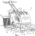
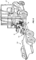
- Fig. 1 illustrates an exemplary concrete saw 10.
- the concrete saw 10 includes a pair of smooth, hard wheels 20, a precisely-aligned element in the form of a cutting blade chuck 30, a prime mover in the form of an electric motor 40, a drive train 50, and a line guide 60.
- the smooth, hard wheels 20 permit the concrete saw 10 to roll over green-state concrete without marring the smooth surface.
- a circular cutting blade 70 may be mounted to the cutting blade chuck 30, and the cutting blade chuck 30 and cutting blade 70 are rotated under the influence of the electric motor 40.
- the prime mover can be an internal combustion engine or any other suitable prime mover.
- the drive train converts torque of the electric motor into rotation of the smooth, hard wheels.
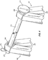
- the line guide 60 includes a bar 80 having a first end 81 pivotably mounted to the right side of the saw 10 and a second end 82 opposite the first end 81, and a disk 83 rotatably mounted to the second end 82 of the bar 80.
- the line guide 60 is pivoted into an operational position in which the first end 81 of the bar 80 is in front of the cutting blade chuck 30, and the disk 83 is resting on the concrete to be cut.
- the disk 83 rolls along the concrete to define a cutting line.
- the cutting blade chuck 30 is precisely aligned with the line guide 60, such that the saw blade 70 cuts into the concrete a kerf that is collinear with the cutting line.
- the line guide 60 is another element of the concrete saw 10 with which the cutting blade chuck 30 (i.e., the precisely-aligned element) is aligned.
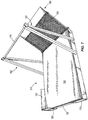
- Figs. 1-3 illustrate a transportation rack or transportation system 110 for the illustrated concrete saw 10.
- the transportation system 110 includes a pair of tubes 120, a plurality of inner brace members 130, a pad 140, a rigid guard 150, first and second support struts 161, 162, a rigid bar 170, a ramp 180, and a latch 190.
- the pair of tubes 120 extend from a front end 210 of the rack 110 (where the rigid guard 150 is) to a rear end 220 of the rack 110 (wherein the ramp 180 is mounted), and define left and right sides 230, 240 of the rack 110.
- the plurality of inner brace members 130 extend between the pair of tubes 120 and are rigidly mounted (e.g., as by welding) to the pair of tubes 120.
- the pair of tubes 120 and the inner brace members 130 define a frame 245 for the rack 110.
- the pair of tubes 120 and inner brace members 130 also define a support surface 250.
- the pair of tubes 120 define a lifting device interface, as will be discussed below with reference to Fig. 8 .
- the pad 140 is supported by the support surface 250 of the frame.
- the pad 140 supports the smooth wheels 20 of the concrete saw 10.
- the pad 140 is about 1,27 cm (1/2") thick and is constructed of thick rubber.
- One example of a suitable pad is the 1,27 cm (1/12") Thick Trailer Mat manufactured of recycled materials by Humane Manufacturing Company LLC of Baraboo, WI.
- the rigid guard 150 is mounted to the frame 245 for protecting the cutting blade chuck 30 during transport at least to the extent of any impacts in excess of the misalignment threshold.
- the rigid guard 150 protects the cutting blade chuck 30 from, for example, debris that fly at the cutting blade chuck 30 during transport, and from any items carelessly thrown into the area where the transportation rack 110 is secured in the transportation vehicle or trailer (collectively, "transporter").
- the first and second support struts 161, 162 are mounted to opposite sides of the frame 245 and extend upwardly on opposite sides of concrete saw 110.
- Each support strut 161, 162 includes a pair of legs 263 which define a triangle with the tubes 120, and an aperture 264 where the pair of legs 263 meet at the top of the support struts 161, 162.
- the rigid bar 170 includes a first end that has an enlarged knob 271 and a second end that includes a retaining hole 272 for accommodating a cotter pin 273 or other retainer. If the arrangement of the concrete saw 10 permits, the rigid bar 170 may extend through a portion of the concrete saw 10.
- the ramp 180 is pivotally mounted to the frame 245 and movable into a deployed condition to facilitate moving the concrete saw 10 onto the pad 140.
- the ramp 180 includes a hinge 281, a transfer edge 282, a mesh portion 283, and a rigid lip 284.
- the rigid lip 284 contacts the ground and the transfer edge 282 is substantially even with the top of the pad 140 to minimize any gap, drop, or step between the ramp 180 and the pad 140.
- the concrete saw 110 is transferred from the ramp 180 to the pad 140 without causing damage to the smooth, hard wheels 20.
- the ramp 180 is pivotable into a stowed condition in which the ramp 180 is pivoted up.
- the ramp 180 is within the footprint of the frame 245 when in the stowed condition. "Within the footprint” means not extending outside of the vertical projection of the frame 245 (i.e., the projection of the frame 245 defined by vertical planes that include the front 210, rear 220, left 230, and right 240 sides of the frame 245).
- one end of the latch 190 is pivotally mounted to the ramp 180, and the opposite end of the latch 190 includes a hook 291.
- the latch 190 can be pivoted to engage the hook 291 in an eye 293 ( Figs. 2 and 3 ) that is mounted to one of the struts 161, 162.
- the latch 190 holds the ramp 180 in the stowed condition.
- Figs. 6 and 7 illustrate another embodiment 310 of the transportation rack, but of a larger size to accommodate a larger concrete saw 320. All elements of the embodiment 310 are the same as those of the first embodiment 110, and are labeled as such. In the second embodiment 310, the rack is larger to accommodate the larger concrete saw 320.
- the transportation system 110 is adapted to be loaded with a lifting device 410 on a transporter 510 for transportation of the saw 10.
- the ramp 180 of an empty transportation rack 110 is unlatched and pivoted into the deployed condition.
- the transfer edge 282 of the ramp 180 is positioned adjacent to the pad 140 in response to the ramp 180 being in the deployed condition.
- the concrete saw 10 is positioned on the transportation rack 110 by rolling the smooth, hard wheel 20 up the ramp 180, across the transfer edge 282, and onto the pad 140 without causing damage to the smooth, hard wheels 20.
- the pad 140 supports the smooth wheels 20.
- the precisely-aligned element 130 is proximate the rigid guard 150.
- the concrete saw 10 is between the support struts 161, 162, such that the support struts 161, 162 are on opposite sides of concrete saw 10.
- the rigid bar 170 is extended between the support struts 161, 162 and secured at opposite ends to the support struts 161, 162. If the concrete saw 10 is so configured, the rigid bar 170 may also extend through a portion of the concrete saw 10 (e.g., a tube permanently affixed to the concrete saw 10).
- the second end of the rigid bar 170 is extended through the apertures 264 on each of the struts 161, 162, such that the rigid bar 170 extends across (or through, as the case may be) a portion of the concrete saw 10 that is on the transportation rack 110.
- the enlarged knob 271 of the first end of the rigid bar 170 is too large to pass through the aperture 264 of the first support strut 161.
- the second end of the rigid bar 170 extends beyond the second strut 162 in cantilever fashion.
- the retaining pin 273 is inserted through the retaining hole 272 in the second end of the rigid bar 170.
- the retaining pin 273 is wider than the aperture 264 of the second strut 162, such that the retaining pin 273 resists movement of the second end of the rigid bar 170 back through the aperture 264.
- the rigid bar 170 is retained in the installed condition until the retaining pin 273 is removed to enable the rigid bar 170 to be slid out of the apertures 264 of the struts 161, 162.
- the rigid bar 170 vertically contains the concrete saw 10 with respect to the frame 245 and limits an amplitude of vertical movement of the concrete saw 10 to limit a dynamic load on the concrete saw 10 arising from transportation of the concrete saw 10.
- the rigid bar 170 may apply a containment load on the concrete saw 10 to hold the smooth wheels 20 in constant contact with the pad 140 during transport.
- the pad 140 absorbs a combination of the containment load and the dynamic load, to the extent such combination exceeds the wheel damage threshold and drive damage threshold, to protect the smooth, hard wheels 20 and drive train 50 from damage.
- the ramp 180 is pivoted into the stowed condition, within the footprint of the frame 245, and latched by inserting the hook 281 of the latch 190 on the eye 293.
- the lifting device 410 lifts the transportation rack 110 bearing the concrete saw 10 and deposits it on the transporter 510 for transportation of the concrete saw 10.
- Straps or other securing members can be used to lash the transportation rack 110 to the transporter 510, such that the load path of the securing members does not apply any load on the concrete saw 10.
- the transporter 510 is used to transport the concrete saw 10 to a desired location.
- the dynamic loads are generated on the transportation rack 110 and concrete saw 10.
- the pad 140 absorbs any dynamic loads and any containment load arising during transport or pushing down by the rigid bar 170, to the extent such loads exceed the wheel damage threshold.
- the smooth, hard wheels 140 are protected from developing flat spots that would cause the wheels 120 to skip and mar the smooth surface of the green-state concrete being cut.
- the rigid guard 150 protects the cutting blade chuck 130 from impacts during transport. In this regard, the rigid guard 150 protects the cutting blade chuck 130 from becoming misaligned as a result of an impact in excess of the misalignment threshold, because the rigid guard 150 absorbs the impact instead of the cutting blade chuck 130.
- a lifting device 410 can be used to unload the transportation rack 110 bearing the concrete saw 10 so that the concrete saw 10 can be used in its intended environment.
- Figs. 9-13 illustrate a third embodiment 610 of the of the transportation rack.
- the rack 610 can accommodate multiple sizes of early entry saws 10.
- the drawings illustrate an early entry saw
- the third embodiment can accommodate other types of concrete saws and is not limited to early entry saws.
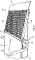
- the transportation rack 610 includes a support plate 620 having an opening or a slot 630 and a rigid guard 640 proximate the slot 630.
- a pad 645 sits on top of the support plate 620 to cushion the saw 10, as discussed in the above embodiments.
- the blade 70 ( Fig. 9 ) of the concrete saw 10 is lowered into the slot 630 once the concrete saw 10 is loaded on the transportation rack 610.
- the rigid guard 640 is mounted to the support plate 620 along at least a portion of the slot 630 and extends upwardly from the support surface 620. The rigid guard 640 shields the saw blade 70 during trasport.
- the rack 610 includes a lifting device interface 120 (e.g., fork lift tubes) to faclitate loading the rack 610 on a transporter for transportation of the saw 10.
- the saw 10 can be transported on the rack 610 with the blade 70 in the operating position (down), which is accommodated by the slot 630.
- the transportation rack 610 also includes a mounting bracket 660 for a winch 670, and a plurality of u-bolt anchors 680 on an opposite side from the mounting bracket 660.
- the mounting bracket 660 and u-bolt anchors 680 are affixed or mounted to the support plate 620.
- the winch 670 and a strap 690 may be of a type commercially available from Rack Strap, Inc. (e.g., model RS1).
- the winch 670 and strap 690 provide a tie-down mechanism that can replace the above-described rigid bar for holding the saw 10 down against the pad.
- the strap 690 is interconnected to the winch 670 and includes a free end with a hook.
- the strap 690 is slung across the saw 10 and the hook is connected to a u-bolt anchor 680. Then the strap 690 is tightened down on the saw 10 by actuating the winch 670.
- the winch 670 applies a tensile load to the strap 690 as the strap engages the saw 10.
- Several winches 670 and straps 690 can be provided, opposite the several u-bolt anchors 680, to accommodate different positioning of the strap 690 for the various sizes of saws 10 that may be positioned on the rack 610.
- the other embodiments of the present invention may incorporate the winch 670 and strap 690 illustrated in Figs. 9-13
- the embodiment of Figs. 9-13 can incorporate the support struts 161, 162 and rigid bar 170 of the first and second embodiments of Figs. 1-8 .
- Any embodiment of the present invention may be provided with the winch 670 and strap 690 arrangement, the support struts 161, 162 and rigid bar 170 arrangement, or both the winch 670 and strap 690 and the support struts 161, 162 and rigid bar 170 arrangement.
- the winch/strap and struts/bar arrangements, and other arrangements performing the same function, can be generally referred to as restraining mechanisms.
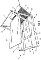
- the transportation rack 610 also includes a ramp 710.
- the ramp 710 includes female clevises 720 on opposite sides.
- the base plate 620 includes male clevises 730 that are received within the female clevises 720.
- a hinge pin 740 is extended through holes in the female and male clevises 720, 730.
- the ramp 710 is pivotally mounted to the frame and movable into a deployed condition ( Figs. 11 and 12 ) to facilitate moving the concrete saw 10 onto the frame and a stowed condition ( Figs. 9 and 10 ).
- the ramp 710 can be held in the stowed condition with a pin 750 and a pivoting bar 760 that is pivotably mounted to an arm 770 that is supported by the bracket 660.
- the ramp is within the footprint of the frame when in the stowed condition.
- the invention provides, among other things, a transportation rack for securing and transporting a concrete saw.
- a transportation rack for securing and transporting a concrete saw.
Description
- The present invention relates to a transportation rack that includes a slot to accommodate the blade of a concrete saw.
- Prior art document
EP 0 837 005 A1 discloses a transportation system comprising a frame including a support surface having openings. The support surface is adapted to support a motor cycle on said support surface, wherein the openings in the support surface are positioned and sized to receive the wheels of the motor cycle. - The invention provides a transportation system and concrete saw combination comprising a concrete saw including at least one wheel for rolling over a concrete surface to be cut, and a saw blade extending below the at least one wheel and adapted to cut the concrete surface, and a transportation system including a frame including a support surface; and an opening in the support surface; wherein the support surface is adapted to support the concrete saw with the wheel on the support surface; wherein the opening in the support surface is positioned and sized to receive the saw blade while the concrete saw is supported by the support surface; and wherein the transportation system is adapted to be loaded on a transporter for transportation of the construction equipment.
- In some embodiments, the at least one wheel of the concrete saw includes a smooth, hard wheel that supports the saw during operation, the transportation system further comprising: a pad supported by the support surface of the frame and supporting the smooth wheel of the construction equipment, the pad absorbing a dynamic load arising during transport. In some embodiments, the transportation system further comprises: a rigid guard mounted to the frame along at least a portion of the opening and extending upwardly from the support surface, the rigid guard shielding the saw blade during transport. In some embodiments, the transportation system further comprises: a restraining mechanism adapted to limit movement of the concrete saw during transport. In some embodiments, the restraining mechanism includes first and second support struts mounted to the frame on opposite sides of the frame and adapted to extend upwardly on opposite sides of the concrete saw, and a rigid bar extending between the support struts. In some embodiments, the restraining mechanism includes a strap having at least one end anchored to the frame. In some embodiments, the strap includes an opposite end also anchored to the frame, the strap extending across the concrete saw. In some embodiments, the restraining mechanism also includes a winch acting on the strap. In some embodiments, the frame includes an anchor and the strap includes a hook for engaging the anchor. In some embodiments, the transportation system further comprises a ramp pivotally mounted to the frame and movable into a deployed condition to facilitate moving the concrete saw onto the frame and a stowed condition; male and female clevises on the frame and ramp; and a hinge pin extending through the male and female clevises to pivotally mount the ramp to the frame. In some embodiments, the ramp is within the footprint of the frame when in the stowed condition. In some embodiments, the transportation system further comprises a lifting device interface adapted to receive portions of a lifting device to facilitate loading and unloading the transportation system onto and off of the transporter. In some embodiments, the lifting device interface includes a pair of fork lift tubes.
- Other aspects of the invention will become apparent by consideration of the detailed description and accompanying drawings. It is noted not all drawings show an opening in the support surface for receiving a saw blade, said opening nevertheless forming part of the present invention.
-
-
Fig. 1 is a perspective view of a transportation rack according to a first embodiment of the present invention, bearing a concrete saw. -
Fig. 2 is a perspective view of the transportation rack ofFig. 1 from another perspective with the concrete saw removed. -
Fig. 3 is a top view of the transportation rack with the pad removed for illustrative purposes. -
Fig. 4 is an enlarged view of the vertical struts and rigid bar of the transportation rack. -
Fig. 5 is an enlarged view of the ramp in a deployed condition. -
Fig. 6 is a perspective view of a transportation rack according to a second embodiment of the present invention, bearing another concrete saw. -
Fig. 7 is a perspective view of the transportation rack ofFig. 6 with the concrete saw removed. -
Fig. 8 illustrates a lifting apparatus lifting the transportation rack and concrete saw for deposit into a transporter. -
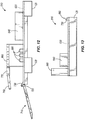
Fig. 9 is a side view of a transportation rack according to a third embodiment of the present invention, bearing another concrete saw. -
Fig. 10 is a perspective view of the third embodiment. -
Fig. 11 is a top view of the third embodiment. -
Fig. 12 is a side view of the third embodiment with the ramp deployed. -
Fig. 13 is an end view of the third embodiment. - Before any embodiments of the invention are explained in detail, it is to be understood that the invention is not limited in its application to the details of construction and the arrangement of components set forth in the following description or illustrated in the following drawings. The invention is capable of other embodiments and of being practiced or of being carried out in various ways.
- The present invention provides a transportation rack for a concrete saw of a type having a smooth, hard wheel that supports the concrete saw of a type having a smooth, hard wheel that supports the concrete saw during operation, a precisely-aligned element, a prime mover, and a drive train for driving the smooth wheel under the influence of the prime mover to propel the concrete saw during operation.
- The term "hard wheel," as used in the present specification, refers to a wheel that includes a hub constructed of rigid materials, such as steel or other metal. The smooth surface around the hard wheel is provided, for example, by a ring of hard rubber. The hard rubber may be referred to as a tire, but is different from traditional tires in that it is not necessarily inflated and provides a substantially unyielding smooth surface. The term "smooth, hard wheel" is intended to include both the hard wheel and the hard rubber tire around the hard wheel, the resulting combination providing a substantially unyielding smooth round surface on which the concrete saw rides.
- The smooth, hard wheel can develop a flat spot in response to an external load being applied to the concrete saw in excess of a wheel damage threshold. The precisely-aligned element can be misaligned in response to an external load applied to the precisely-aligned element in excess of a misalignment threshold. The drive train is subject to damage in response to an external load being applied to the concrete saw in excess of a drive damage threshold. The term "external load" means a load in excess of loads that are present during ordinary operation of the concrete saw. For example, the weight of the concrete saw is a load borne by the smooth wheel during ordinary operation, and would not be an "external load" as that term is used herein.
- The term "precisely aligned," as used in this specification, means that successful use of the concrete saw relies on such element being maintained in alignment with respect to another element of the concrete saw. Misalignment of the precisely-aligned element refers to movement of the precisely-aligned element out of alignment with the other element. Should the precisely-aligned element become misaligned, the concrete saw will fail an essential purpose.
- An example of a concrete saw for which the transportation rack of the present invention is suitable is a class of concrete saws called "early entry" saws. Early entry saws are adapted to cut a straight line in green-state (i.e., still curing and hardening) concrete. One specific, commercially-available concrete saw of this type is the SOFF-CUT early entry saw manufactured and sold by Husqvarna. Although the accompanying drawings illustrate an early entry saw, it is to be understood that the present invention may accommodate other types of concrete saw and is not limited to early entry saws.
-
Fig. 1 illustrates an exemplary concrete saw 10. Theconcrete saw 10 includes a pair of smooth,hard wheels 20, a precisely-aligned element in the form of acutting blade chuck 30, a prime mover in the form of anelectric motor 40, adrive train 50, and aline guide 60. The smooth,hard wheels 20 permit the concrete saw 10 to roll over green-state concrete without marring the smooth surface. Acircular cutting blade 70 may be mounted to thecutting blade chuck 30, and thecutting blade chuck 30 andcutting blade 70 are rotated under the influence of theelectric motor 40. In other embodiments the prime mover can be an internal combustion engine or any other suitable prime mover. The drive train converts torque of the electric motor into rotation of the smooth, hard wheels. - The
line guide 60 includes abar 80 having afirst end 81 pivotably mounted to the right side of thesaw 10 and asecond end 82 opposite thefirst end 81, and adisk 83 rotatably mounted to thesecond end 82 of thebar 80. In operation, theline guide 60 is pivoted into an operational position in which thefirst end 81 of thebar 80 is in front of thecutting blade chuck 30, and thedisk 83 is resting on the concrete to be cut. As the saw 10 moves forward, thedisk 83 rolls along the concrete to define a cutting line. Thecutting blade chuck 30 is precisely aligned with theline guide 60, such that thesaw blade 70 cuts into the concrete a kerf that is collinear with the cutting line. In this regard, theline guide 60 is another element of the concrete saw 10 with which the cutting blade chuck 30 (i.e., the precisely-aligned element) is aligned. -
Figs. 1-3 illustrate a transportation rack ortransportation system 110 for the illustrated concrete saw 10. Thetransportation system 110 includes a pair oftubes 120, a plurality ofinner brace members 130, apad 140, arigid guard 150, first and second support struts 161, 162, arigid bar 170, aramp 180, and alatch 190. - The pair of
tubes 120 extend from afront end 210 of the rack 110 (where therigid guard 150 is) to arear end 220 of the rack 110 (wherein theramp 180 is mounted), and define left andright sides rack 110. The plurality ofinner brace members 130 extend between the pair oftubes 120 and are rigidly mounted (e.g., as by welding) to the pair oftubes 120. In this regard, the pair oftubes 120 and theinner brace members 130 define aframe 245 for therack 110. The pair oftubes 120 andinner brace members 130 also define asupport surface 250. The pair oftubes 120 define a lifting device interface, as will be discussed below with reference toFig. 8 . - The
pad 140 is supported by thesupport surface 250 of the frame. Thepad 140 supports thesmooth wheels 20 of the concrete saw 10. In the illustrated embodiment, thepad 140 is about 1,27 cm (1/2") thick and is constructed of thick rubber. One example of a suitable pad is the 1,27 cm (1/12") Thick Trailer Mat manufactured of recycled materials by Humane Manufacturing Company LLC of Baraboo, WI. - The
rigid guard 150 is mounted to theframe 245 for protecting thecutting blade chuck 30 during transport at least to the extent of any impacts in excess of the misalignment threshold. Therigid guard 150 protects thecutting blade chuck 30 from, for example, debris that fly at thecutting blade chuck 30 during transport, and from any items carelessly thrown into the area where thetransportation rack 110 is secured in the transportation vehicle or trailer (collectively, "transporter"). - Referring to
Fig. 4 , the first and second support struts 161, 162 are mounted to opposite sides of theframe 245 and extend upwardly on opposite sides of concrete saw 110. Eachsupport strut legs 263 which define a triangle with thetubes 120, and anaperture 264 where the pair oflegs 263 meet at the top of the support struts 161, 162. Therigid bar 170 includes a first end that has anenlarged knob 271 and a second end that includes a retaininghole 272 for accommodating acotter pin 273 or other retainer. If the arrangement of the concrete saw 10 permits, therigid bar 170 may extend through a portion of the concrete saw 10. - Referring to
Fig. 5 , theramp 180 is pivotally mounted to theframe 245 and movable into a deployed condition to facilitate moving the concrete saw 10 onto thepad 140. Theramp 180 includes ahinge 281, atransfer edge 282, amesh portion 283, and arigid lip 284. When in a deployed condition (as illustrated inFig. 5 ), therigid lip 284 contacts the ground and thetransfer edge 282 is substantially even with the top of thepad 140 to minimize any gap, drop, or step between theramp 180 and thepad 140. As a result of the minimal gap, the concrete saw 110 is transferred from theramp 180 to thepad 140 without causing damage to the smooth,hard wheels 20. - Returning to
Figs. 1-3 , theramp 180 is pivotable into a stowed condition in which theramp 180 is pivoted up. In some embodiments, theramp 180 is within the footprint of theframe 245 when in the stowed condition. "Within the footprint" means not extending outside of the vertical projection of the frame 245 (i.e., the projection of theframe 245 defined by vertical planes that include the front 210, rear 220, left 230, and right 240 sides of the frame 245). - As illustrated in
Fig. 5 , one end of thelatch 190 is pivotally mounted to theramp 180, and the opposite end of thelatch 190 includes ahook 291. Thelatch 190 can be pivoted to engage thehook 291 in an eye 293 (Figs. 2 and3 ) that is mounted to one of thestruts hook 291 is received in theeye 293, thelatch 190 holds theramp 180 in the stowed condition. -
Figs. 6 and7 illustrate anotherembodiment 310 of the transportation rack, but of a larger size to accommodate a larger concrete saw 320. All elements of theembodiment 310 are the same as those of thefirst embodiment 110, and are labeled as such. In thesecond embodiment 310, the rack is larger to accommodate the larger concrete saw 320. - With reference to
Fig. 8 , thetransportation system 110 is adapted to be loaded with alifting device 410 on atransporter 510 for transportation of thesaw 10. - In operation, the
ramp 180 of anempty transportation rack 110 is unlatched and pivoted into the deployed condition. Thetransfer edge 282 of theramp 180 is positioned adjacent to thepad 140 in response to theramp 180 being in the deployed condition. - The concrete saw 10 is positioned on the
transportation rack 110 by rolling the smooth,hard wheel 20 up theramp 180, across thetransfer edge 282, and onto thepad 140 without causing damage to the smooth,hard wheels 20. Thepad 140 supports thesmooth wheels 20. The precisely-alignedelement 130 is proximate therigid guard 150. The concrete saw 10 is between the support struts 161, 162, such that the support struts 161, 162 are on opposite sides of concrete saw 10. - The
rigid bar 170 is extended between the support struts 161, 162 and secured at opposite ends to the support struts 161, 162. If the concrete saw 10 is so configured, therigid bar 170 may also extend through a portion of the concrete saw 10 (e.g., a tube permanently affixed to the concrete saw 10). - More specifically, the second end of the
rigid bar 170 is extended through theapertures 264 on each of thestruts rigid bar 170 extends across (or through, as the case may be) a portion of the concrete saw 10 that is on thetransportation rack 110. Theenlarged knob 271 of the first end of therigid bar 170 is too large to pass through theaperture 264 of thefirst support strut 161. The second end of therigid bar 170 extends beyond thesecond strut 162 in cantilever fashion. The retainingpin 273 is inserted through the retaininghole 272 in the second end of therigid bar 170. The retainingpin 273 is wider than theaperture 264 of thesecond strut 162, such that the retainingpin 273 resists movement of the second end of therigid bar 170 back through theaperture 264. In this regard, therigid bar 170 is retained in the installed condition until the retainingpin 273 is removed to enable therigid bar 170 to be slid out of theapertures 264 of thestruts - The
rigid bar 170 vertically contains the concrete saw 10 with respect to theframe 245 and limits an amplitude of vertical movement of the concrete saw 10 to limit a dynamic load on the concrete saw 10 arising from transportation of the concrete saw 10. - The
rigid bar 170 may apply a containment load on the concrete saw 10 to hold thesmooth wheels 20 in constant contact with thepad 140 during transport. Thepad 140 absorbs a combination of the containment load and the dynamic load, to the extent such combination exceeds the wheel damage threshold and drive damage threshold, to protect the smooth,hard wheels 20 and drivetrain 50 from damage. - The
ramp 180 is pivoted into the stowed condition, within the footprint of theframe 245, and latched by inserting thehook 281 of thelatch 190 on theeye 293. - Then portions of the
lifting device 410 are inserted into the first andsecond tubes 120, thelifting device 410 lifts thetransportation rack 110 bearing the concrete saw 10 and deposits it on thetransporter 510 for transportation of the concrete saw 10. Straps or other securing members can be used to lash thetransportation rack 110 to thetransporter 510, such that the load path of the securing members does not apply any load on the concrete saw 10. - The
transporter 510 is used to transport the concrete saw 10 to a desired location. During transport, the dynamic loads are generated on thetransportation rack 110 and concrete saw 10. Thepad 140 absorbs any dynamic loads and any containment load arising during transport or pushing down by therigid bar 170, to the extent such loads exceed the wheel damage threshold. As a result, the smooth,hard wheels 140 are protected from developing flat spots that would cause thewheels 120 to skip and mar the smooth surface of the green-state concrete being cut. - The
rigid guard 150 protects thecutting blade chuck 130 from impacts during transport. In this regard, therigid guard 150 protects thecutting blade chuck 130 from becoming misaligned as a result of an impact in excess of the misalignment threshold, because therigid guard 150 absorbs the impact instead of thecutting blade chuck 130. - Once at a desired site, a
lifting device 410 can be used to unload thetransportation rack 110 bearing the concrete saw 10 so that the concrete saw 10 can be used in its intended environment. -
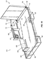
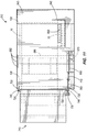
Figs. 9-13 illustrate athird embodiment 610 of the of the transportation rack. Therack 610 can accommodate multiple sizes of early entry saws 10. Although the drawings illustrate an early entry saw, the third embodiment can accommodate other types of concrete saws and is not limited to early entry saws. - Referring to
Fig. 10 , thetransportation rack 610 includes asupport plate 620 having an opening or aslot 630 and arigid guard 640 proximate theslot 630. Apad 645 sits on top of thesupport plate 620 to cushion thesaw 10, as discussed in the above embodiments. The blade 70 (Fig. 9 ) of the concrete saw 10 is lowered into theslot 630 once the concrete saw 10 is loaded on thetransportation rack 610. Therigid guard 640 is mounted to thesupport plate 620 along at least a portion of theslot 630 and extends upwardly from thesupport surface 620. Therigid guard 640 shields thesaw blade 70 during trasport. As with other embodiments of the invention, therack 610 includes a lifting device interface 120 (e.g., fork lift tubes) to faclitate loading therack 610 on a transporter for transportation of thesaw 10. Thesaw 10 can be transported on therack 610 with theblade 70 in the operating position (down), which is accommodated by theslot 630. - The
transportation rack 610 also includes a mountingbracket 660 for awinch 670, and a plurality ofu-bolt anchors 680 on an opposite side from the mountingbracket 660. The mountingbracket 660 andu-bolt anchors 680 are affixed or mounted to thesupport plate 620. - The
winch 670 and astrap 690 may be of a type commercially available from Rack Strap, Inc. (e.g., model RS1). Thewinch 670 andstrap 690 provide a tie-down mechanism that can replace the above-described rigid bar for holding thesaw 10 down against the pad. Thestrap 690 is interconnected to thewinch 670 and includes a free end with a hook. Thestrap 690 is slung across thesaw 10 and the hook is connected to au-bolt anchor 680. Then thestrap 690 is tightened down on thesaw 10 by actuating thewinch 670. Thewinch 670 applies a tensile load to thestrap 690 as the strap engages thesaw 10.Several winches 670 andstraps 690 can be provided, opposite the severalu-bolt anchors 680, to accommodate different positioning of thestrap 690 for the various sizes ofsaws 10 that may be positioned on therack 610. - The other embodiments of the present invention (e.g., the first embodiment illustrated in
Figs. 1-5 and the second embodiment illustrated inFigs. 6-7 ) may incorporate thewinch 670 andstrap 690 illustrated inFigs. 9-13 , and the embodiment ofFigs. 9-13 can incorporate the support struts 161, 162 andrigid bar 170 of the first and second embodiments ofFigs. 1-8 . Any embodiment of the present invention may be provided with thewinch 670 andstrap 690 arrangement, the support struts 161, 162 andrigid bar 170 arrangement, or both thewinch 670 andstrap 690 and the support struts 161, 162 andrigid bar 170 arrangement. The winch/strap and struts/bar arrangements, and other arrangements performing the same function, can be generally referred to as restraining mechanisms. - The
transportation rack 610 also includes aramp 710. Theramp 710 includesfemale clevises 720 on opposite sides. Thebase plate 620 includesmale clevises 730 that are received within thefemale clevises 720. Ahinge pin 740 is extended through holes in the female andmale clevises ramp 710 is pivotally mounted to the frame and movable into a deployed condition (Figs. 11 and12 ) to facilitate moving the concrete saw 10 onto the frame and a stowed condition (Figs. 9 and10 ). Theramp 710 can be held in the stowed condition with apin 750 and a pivotingbar 760 that is pivotably mounted to anarm 770 that is supported by thebracket 660. The ramp is within the footprint of the frame when in the stowed condition. - Thus, the invention provides, among other things, a transportation rack for securing and transporting a concrete saw. Various features and advantages of the invention are set forth in the following claims.
Claims (13)
- A. transportation system and concrete saw combination comprising;a concrete saw (10) including:at least one wheel (20) for rolling over a concrete surface to be cut, anda saw blade (70) extending below the at least one wheels and adapted to cut the concrete surface; anda transportation system (110) including:a frame (245) including a support surface (250), andan opening (630) in the support surface;wherein the support surface (250) is adapted to support the concrete saw (10) with the wheel (20) on the support surface;wherein the opening (630) in the support surface (250) is positioned and sized to receive the saw blade (70) while the concrete saw (10) is supported by the support surface; andwherein the transportation system is adapted to be loaded on a transporter for transportation of the concrete saw.
- The transportation system and concrete saw combination of claim 1, wherein the at least one wheel (20) of the concrete saw includes a smooth, hard wheel that supports the saw during operation, the transportation system further comprising:a pad (140) supported by the support surface of the frame and supporting the smooth wheel of the concrete saw the pad absorbing a dynamic load arising during transport.
- The transportation system and concrete saw combination of claim 1, further comprising: a rigid guard (150) mounted to the frame along at least a portion of the opening (630) and extending upwardly from the support surface, the rigid guard shielding the saw blade during transport.
- The transportation system and concrete saw combination of claim 1, further comprising: a restraining mechanism adapted to limit movement of the concrete saw during transport.
- The transportation system and concrete saw combination of claim 4, wherein the restraining mechanism includes first and second support struts (161,162) mounted to the frame on opposite sides of the frame and adapted to extend upwardly on opposite sides of the concrete saw, and a rigid bar (170) extending between the support struts.
- The transportation system and concrete saw combination of claim 4, wherein the restraining mechanism includes a strap (690) having at least one end anchored to the frame.
- The transportation system and concrete saw combination of claim 6, wherein the strap (690) includes an opposite end also anchored to the frame, the strap extending across the concrete saw.
- The transportation system and concrete saw combination of claim 6, wherein the restraining mechanism also includes a winch (670) acting on the strap.
- The transportation system and concrete saw combination of claim 6, wherein the frame includes an anchor (680) and the strap includes a hook for engaging the anchor.
- The transportation system and concrete saw combination of claim 1, further comprising a ramp (180) pivotally mounted to the frame and movable into a deployed condition to facilitate moving the concrete saw onto the frame and a stowed condition; male and female clevises (720,730) on the frame and ramp, and a hinge pin (740) extending through the male and female clevises to pivotally mount the ramp to the frame.
- The transportation system and concrete saw combination of claim 10, wherein the ramp (180) is within the footprint of the frame when in the stowed condition.
- The transportation system and concrete saw combination of claim 1, further comprising lifting device interface (120) adapted to receive portions of a lifting device to facilitate loading and unloading the transportation system onto and off of the transporter.
- The transportation system and concrete saw combination of claim 12, wherein the lifting device interface (120) includes a pair of fork lift tubes.
Applications Claiming Priority (2)
| Application Number | Priority Date | Filing Date | Title |
|---|---|---|---|
| US201261589861P | 2012-01-23 | 2012-01-23 | |
| PCT/US2013/022693 WO2013112546A1 (en) | 2012-01-23 | 2013-01-23 | Concrete saw rack having slot to accommodate blade |
Publications (2)
| Publication Number | Publication Date |
|---|---|
| EP2807085A1 EP2807085A1 (en) | 2014-12-03 |
| EP2807085B1 true EP2807085B1 (en) | 2016-03-30 |
Family
ID=47747773
Family Applications (1)
| Application Number | Title | Priority Date | Filing Date |
|---|---|---|---|
| EP13705623.0A Active EP2807085B1 (en) | 2012-01-23 | 2013-01-23 | Concrete saw rack having slot to accommodate blade |
Country Status (4)
| Country | Link |
|---|---|
| US (1) | US20150033992A1 (en) |
| EP (1) | EP2807085B1 (en) |
| CA (1) | CA2860902C (en) |
| WO (1) | WO2013112546A1 (en) |
Families Citing this family (7)
| Publication number | Priority date | Publication date | Assignee | Title |
|---|---|---|---|---|
| US9278840B2 (en) * | 2014-06-23 | 2016-03-08 | Amazon Technologies, Inc. | Palletizing mobile drive units |
| JP6428732B2 (en) * | 2016-08-30 | 2018-11-28 | トヨタ自動車株式会社 | Vehicle control device |
| FI126980B (en) * | 2016-10-05 | 2017-09-15 | Hartwall K Oy Ab | Logistics system, adapter pallet and load carrier |
| US10343631B2 (en) * | 2016-12-28 | 2019-07-09 | Uber Technologies, Inc. | Decreasing autonomous vehicle power consumption |
| US10222799B2 (en) * | 2017-03-14 | 2019-03-05 | International Business Machines Corporation | Autonomous vehicle pickup directed by socially derived meta data in public environments |
| US10489721B2 (en) * | 2017-05-23 | 2019-11-26 | Uatc, Llc | Path segment risk regression system for on-demand transportation services |
| CN114684575A (en) * | 2020-12-30 | 2022-07-01 | 郑州深澜动力科技有限公司 | Automatic lifting device for tray stand column and tray conveying line |
Family Cites Families (23)
| Publication number | Priority date | Publication date | Assignee | Title |
|---|---|---|---|---|
| US1555022A (en) * | 1923-11-17 | 1925-09-29 | John C Proctor | Apparatus for handling building material |
| US1836362A (en) * | 1925-04-27 | 1931-12-15 | Libbey Owens Ford Glass Co | Glass buck |
| US1637960A (en) * | 1926-01-26 | 1927-08-02 | Robert T Romine | Portable rack |
| US2665020A (en) * | 1950-11-08 | 1954-01-05 | Charles E Whittle | Self-loading and unloading vehicle for palletized loads |
| US2936985A (en) * | 1955-12-09 | 1960-05-17 | Kaiser Aluminium Chem Corp | Pallet having swingable loading and unloading ramps |
| US3735713A (en) * | 1972-03-23 | 1973-05-29 | Pullman Inc | Cargo transporting device |
| US3753407A (en) * | 1972-04-05 | 1973-08-21 | Kaiser Aluminium Chem Corp | Convertible shipping pallet |
| US4166833A (en) * | 1973-10-23 | 1979-09-04 | The Plastic Forming Company, Inc. | Method and apparatus for molding a plastic article |
| FR2321433A1 (en) * | 1975-08-22 | 1977-03-18 | Sodic | Mechanical handling pallet for two wheeled units - has angle iron frame with fork lift entry and pairs of bars forming wheel retainer slots |
| FR2503095A1 (en) * | 1981-03-31 | 1982-10-08 | Caoutchouc Manuf Plastique | DEVICE FOR THE PACKAGING OF LARGE-LENGTH ARTICLES, IN PARTICULAR TRANSPORT BANDS |
| DE58906907D1 (en) * | 1989-06-03 | 1994-03-17 | Clemens Fricke Industrieverpac | Shipping packaging for ready-to-use motorcycles and the like. |
| US5398832A (en) * | 1992-10-27 | 1995-03-21 | Clive-Smith; Martin | Lashings in folding flatrack |
| US5639174A (en) * | 1996-04-15 | 1997-06-17 | The United States Of America As Represented By The Secretary Of The Army | Double hinged modular cargo unit |
| US5931435A (en) * | 1996-09-30 | 1999-08-03 | Champion International Corporation | Packaging and distribution system for rolled or cylindrical articles |
| EP0837005A1 (en) * | 1996-10-16 | 1998-04-22 | Wolf Dietrich Kempf | Shipping and storing appliance in particular for motor cycles |
| US6006676A (en) * | 1997-07-25 | 1999-12-28 | Worthington Industries, Inc. | Modular packaging skid |
| US6216607B1 (en) * | 2000-03-20 | 2001-04-17 | William R. Cuddy | Reusable pallet |
| US20030141207A1 (en) * | 2002-01-31 | 2003-07-31 | Sammy Pai | Bicycle packing device |
| US7077067B2 (en) * | 2002-07-24 | 2006-07-18 | Toyota Motor Manufacturing North America, Inc. | Adjustable hold-down assembly |
| US7918165B2 (en) * | 2007-03-30 | 2011-04-05 | Magna International Inc. | Component container with dunnage and method for using the same |
| US7971733B2 (en) * | 2007-09-18 | 2011-07-05 | Amcor Packaging Distribution | Window pallet and method of use thereof |
| US8256357B2 (en) * | 2008-10-29 | 2012-09-04 | James Kelly | Process and structure for servicing a vehicle over a service pit |
| DE102009008218A1 (en) * | 2009-02-10 | 2010-08-26 | Andreas Hundt | Transport system i.e. transport pallet, for transporting coated sheet- and folded parts by industrial vehicle and truck, has rubber mat granule, swivel bracket and pipe covered with PVC tube |
-
2013
- 2013-01-23 US US14/374,142 patent/US20150033992A1/en not_active Abandoned
- 2013-01-23 WO PCT/US2013/022693 patent/WO2013112546A1/en active Application Filing
- 2013-01-23 EP EP13705623.0A patent/EP2807085B1/en active Active
- 2013-01-23 CA CA2860902A patent/CA2860902C/en active Active
Also Published As
| Publication number | Publication date |
|---|---|
| EP2807085A1 (en) | 2014-12-03 |
| US20150033992A1 (en) | 2015-02-05 |
| CA2860902C (en) | 2020-05-05 |
| WO2013112546A1 (en) | 2013-08-01 |
| CA2860902A1 (en) | 2013-08-01 |
Similar Documents
| Publication | Publication Date | Title |
|---|---|---|
| EP2807085B1 (en) | Concrete saw rack having slot to accommodate blade | |
| US6000903A (en) | Shipping frame for fan section of aircraft engine | |
| US7717656B2 (en) | Attachment device for moving cargo containers | |
| US8672594B1 (en) | Hauling apparatus, system, and method of use | |
| KR20140088042A (en) | Transportation device | |
| WO2010128340A2 (en) | Fall prevention system and access ladder | |
| US7985043B2 (en) | Transport trailer | |
| US6062800A (en) | Forklift frame and mounting kit | |
| US8579565B2 (en) | Padded surface transportation apparatus for construction equipment | |
| CA2377258C (en) | Apparatus and method for unloading a center beam railcar | |
| US5137194A (en) | Ladder support rack | |
| EP2780248B1 (en) | Padded surface transportation apparatus for construction equipment | |
| KR101417298B1 (en) | Device for installing goods protecter | |
| KR101849521B1 (en) | Ladder car that can work at low places | |
| JP2009274775A (en) | Hanging tool of flexible container bag | |
| CN209010091U (en) | A kind of fork truck anti-skid device for the bucket that inclines | |
| WO2003068616A1 (en) | Reel-transporting platform | |
| WO1999002404A1 (en) | Shipping frame for fan section of aircraft engine | |
| JP5421888B2 (en) | Movable cradle for cargo vehicles | |
| JP3851102B2 (en) | Hose car handling equipment | |
| JP5592756B2 (en) | Rear-slip support device for cargo carrier | |
| JPH0911797A (en) | Ladder with fixing means | |
| JP2020070127A (en) | Apparatus and method for drawing cargo | |
| JPH0380720B2 (en) | ||
| US20100025959A1 (en) | Trailer and Jack System |
Legal Events
| Date | Code | Title | Description |
|---|---|---|---|
| PUAI | Public reference made under article 153(3) epc to a published international application that has entered the european phase |
Free format text: ORIGINAL CODE: 0009012 |
|
| 17P | Request for examination filed |
Effective date: 20140714 |
|
| AK | Designated contracting states |
Kind code of ref document: A1 Designated state(s): AL AT BE BG CH CY CZ DE DK EE ES FI FR GB GR HR HU IE IS IT LI LT LU LV MC MK MT NL NO PL PT RO RS SE SI SK SM TR |
|
| DAX | Request for extension of the european patent (deleted) | ||
| GRAP | Despatch of communication of intention to grant a patent |
Free format text: ORIGINAL CODE: EPIDOSNIGR1 |
|
| GRAJ | Information related to disapproval of communication of intention to grant by the applicant or resumption of examination proceedings by the epo deleted |
Free format text: ORIGINAL CODE: EPIDOSDIGR1 |
|
| RIC1 | Information provided on ipc code assigned before grant |
Ipc: B65D 85/68 20060101ALI20150825BHEP Ipc: B28D 1/04 20060101ALN20150825BHEP Ipc: B65D 19/44 20060101AFI20150825BHEP |
|
| GRAP | Despatch of communication of intention to grant a patent |
Free format text: ORIGINAL CODE: EPIDOSNIGR1 |
|
| INTG | Intention to grant announced |
Effective date: 20150914 |
|
| INTC | Intention to grant announced (deleted) | ||
| RIC1 | Information provided on ipc code assigned before grant |
Ipc: B65D 19/44 20060101AFI20150924BHEP Ipc: B28D 1/04 20060101ALN20150924BHEP Ipc: B65D 85/68 20060101ALI20150924BHEP |
|
| INTG | Intention to grant announced |
Effective date: 20151006 |
|
| GRAS | Grant fee paid |
Free format text: ORIGINAL CODE: EPIDOSNIGR3 |
|
| GRAA | (expected) grant |
Free format text: ORIGINAL CODE: 0009210 |
|
| AK | Designated contracting states |
Kind code of ref document: B1 Designated state(s): AL AT BE BG CH CY CZ DE DK EE ES FI FR GB GR HR HU IE IS IT LI LT LU LV MC MK MT NL NO PL PT RO RS SE SI SK SM TR |
|
| REG | Reference to a national code |
Ref country code: GB Ref legal event code: FG4D |
|
| REG | Reference to a national code |
Ref country code: CH Ref legal event code: EP |
|
| REG | Reference to a national code |
Ref country code: AT Ref legal event code: REF Ref document number: 785099 Country of ref document: AT Kind code of ref document: T Effective date: 20160415 |
|
| REG | Reference to a national code |
Ref country code: IE Ref legal event code: FG4D |
|
| REG | Reference to a national code |
Ref country code: DE Ref legal event code: R096 Ref document number: 602013005951 Country of ref document: DE |
|
| REG | Reference to a national code |
Ref country code: LT Ref legal event code: MG4D |
|
| PG25 | Lapsed in a contracting state [announced via postgrant information from national office to epo] |
Ref country code: NO Free format text: LAPSE BECAUSE OF FAILURE TO SUBMIT A TRANSLATION OF THE DESCRIPTION OR TO PAY THE FEE WITHIN THE PRESCRIBED TIME-LIMIT Effective date: 20160630 Ref country code: GR Free format text: LAPSE BECAUSE OF FAILURE TO SUBMIT A TRANSLATION OF THE DESCRIPTION OR TO PAY THE FEE WITHIN THE PRESCRIBED TIME-LIMIT Effective date: 20160701 Ref country code: HR Free format text: LAPSE BECAUSE OF FAILURE TO SUBMIT A TRANSLATION OF THE DESCRIPTION OR TO PAY THE FEE WITHIN THE PRESCRIBED TIME-LIMIT Effective date: 20160330 Ref country code: FI Free format text: LAPSE BECAUSE OF FAILURE TO SUBMIT A TRANSLATION OF THE DESCRIPTION OR TO PAY THE FEE WITHIN THE PRESCRIBED TIME-LIMIT Effective date: 20160330 |
|
| REG | Reference to a national code |
Ref country code: NL Ref legal event code: MP Effective date: 20160330 |
|
| REG | Reference to a national code |
Ref country code: AT Ref legal event code: MK05 Ref document number: 785099 Country of ref document: AT Kind code of ref document: T Effective date: 20160330 |
|
| PG25 | Lapsed in a contracting state [announced via postgrant information from national office to epo] |
Ref country code: LV Free format text: LAPSE BECAUSE OF FAILURE TO SUBMIT A TRANSLATION OF THE DESCRIPTION OR TO PAY THE FEE WITHIN THE PRESCRIBED TIME-LIMIT Effective date: 20160330 Ref country code: SE Free format text: LAPSE BECAUSE OF FAILURE TO SUBMIT A TRANSLATION OF THE DESCRIPTION OR TO PAY THE FEE WITHIN THE PRESCRIBED TIME-LIMIT Effective date: 20160330 Ref country code: RS Free format text: LAPSE BECAUSE OF FAILURE TO SUBMIT A TRANSLATION OF THE DESCRIPTION OR TO PAY THE FEE WITHIN THE PRESCRIBED TIME-LIMIT Effective date: 20160330 Ref country code: LT Free format text: LAPSE BECAUSE OF FAILURE TO SUBMIT A TRANSLATION OF THE DESCRIPTION OR TO PAY THE FEE WITHIN THE PRESCRIBED TIME-LIMIT Effective date: 20160330 |
|
| PG25 | Lapsed in a contracting state [announced via postgrant information from national office to epo] |
Ref country code: NL Free format text: LAPSE BECAUSE OF FAILURE TO SUBMIT A TRANSLATION OF THE DESCRIPTION OR TO PAY THE FEE WITHIN THE PRESCRIBED TIME-LIMIT Effective date: 20160330 |
|
| PG25 | Lapsed in a contracting state [announced via postgrant information from national office to epo] |
Ref country code: PL Free format text: LAPSE BECAUSE OF FAILURE TO SUBMIT A TRANSLATION OF THE DESCRIPTION OR TO PAY THE FEE WITHIN THE PRESCRIBED TIME-LIMIT Effective date: 20160330 Ref country code: EE Free format text: LAPSE BECAUSE OF FAILURE TO SUBMIT A TRANSLATION OF THE DESCRIPTION OR TO PAY THE FEE WITHIN THE PRESCRIBED TIME-LIMIT Effective date: 20160330 Ref country code: IS Free format text: LAPSE BECAUSE OF FAILURE TO SUBMIT A TRANSLATION OF THE DESCRIPTION OR TO PAY THE FEE WITHIN THE PRESCRIBED TIME-LIMIT Effective date: 20160730 |
|
| PG25 | Lapsed in a contracting state [announced via postgrant information from national office to epo] |
Ref country code: AT Free format text: LAPSE BECAUSE OF FAILURE TO SUBMIT A TRANSLATION OF THE DESCRIPTION OR TO PAY THE FEE WITHIN THE PRESCRIBED TIME-LIMIT Effective date: 20160330 Ref country code: ES Free format text: LAPSE BECAUSE OF FAILURE TO SUBMIT A TRANSLATION OF THE DESCRIPTION OR TO PAY THE FEE WITHIN THE PRESCRIBED TIME-LIMIT Effective date: 20160330 Ref country code: SM Free format text: LAPSE BECAUSE OF FAILURE TO SUBMIT A TRANSLATION OF THE DESCRIPTION OR TO PAY THE FEE WITHIN THE PRESCRIBED TIME-LIMIT Effective date: 20160330 Ref country code: PT Free format text: LAPSE BECAUSE OF FAILURE TO SUBMIT A TRANSLATION OF THE DESCRIPTION OR TO PAY THE FEE WITHIN THE PRESCRIBED TIME-LIMIT Effective date: 20160801 Ref country code: RO Free format text: LAPSE BECAUSE OF FAILURE TO SUBMIT A TRANSLATION OF THE DESCRIPTION OR TO PAY THE FEE WITHIN THE PRESCRIBED TIME-LIMIT Effective date: 20160330 Ref country code: SK Free format text: LAPSE BECAUSE OF FAILURE TO SUBMIT A TRANSLATION OF THE DESCRIPTION OR TO PAY THE FEE WITHIN THE PRESCRIBED TIME-LIMIT Effective date: 20160330 Ref country code: CZ Free format text: LAPSE BECAUSE OF FAILURE TO SUBMIT A TRANSLATION OF THE DESCRIPTION OR TO PAY THE FEE WITHIN THE PRESCRIBED TIME-LIMIT Effective date: 20160330 |
|
| PG25 | Lapsed in a contracting state [announced via postgrant information from national office to epo] |
Ref country code: BE Free format text: LAPSE BECAUSE OF FAILURE TO SUBMIT A TRANSLATION OF THE DESCRIPTION OR TO PAY THE FEE WITHIN THE PRESCRIBED TIME-LIMIT Effective date: 20160330 Ref country code: IT Free format text: LAPSE BECAUSE OF FAILURE TO SUBMIT A TRANSLATION OF THE DESCRIPTION OR TO PAY THE FEE WITHIN THE PRESCRIBED TIME-LIMIT Effective date: 20160330 |
|
| REG | Reference to a national code |
Ref country code: DE Ref legal event code: R097 Ref document number: 602013005951 Country of ref document: DE |
|
| REG | Reference to a national code |
Ref country code: FR Ref legal event code: PLFP Year of fee payment: 5 |
|
| PG25 | Lapsed in a contracting state [announced via postgrant information from national office to epo] |
Ref country code: DK Free format text: LAPSE BECAUSE OF FAILURE TO SUBMIT A TRANSLATION OF THE DESCRIPTION OR TO PAY THE FEE WITHIN THE PRESCRIBED TIME-LIMIT Effective date: 20160330 |
|
| PLBE | No opposition filed within time limit |
Free format text: ORIGINAL CODE: 0009261 |
|
| STAA | Information on the status of an ep patent application or granted ep patent |
Free format text: STATUS: NO OPPOSITION FILED WITHIN TIME LIMIT |
|
| 26N | No opposition filed |
Effective date: 20170103 |
|
| PG25 | Lapsed in a contracting state [announced via postgrant information from national office to epo] |
Ref country code: SI Free format text: LAPSE BECAUSE OF FAILURE TO SUBMIT A TRANSLATION OF THE DESCRIPTION OR TO PAY THE FEE WITHIN THE PRESCRIBED TIME-LIMIT Effective date: 20160330 |
|
| REG | Reference to a national code |
Ref country code: CH Ref legal event code: PL |
|
| PG25 | Lapsed in a contracting state [announced via postgrant information from national office to epo] |
Ref country code: MC Free format text: LAPSE BECAUSE OF FAILURE TO SUBMIT A TRANSLATION OF THE DESCRIPTION OR TO PAY THE FEE WITHIN THE PRESCRIBED TIME-LIMIT Effective date: 20160330 |
|
| PG25 | Lapsed in a contracting state [announced via postgrant information from national office to epo] |
Ref country code: CH Free format text: LAPSE BECAUSE OF NON-PAYMENT OF DUE FEES Effective date: 20170131 Ref country code: LI Free format text: LAPSE BECAUSE OF NON-PAYMENT OF DUE FEES Effective date: 20170131 |
|
| REG | Reference to a national code |
Ref country code: IE Ref legal event code: MM4A |
|
| PG25 | Lapsed in a contracting state [announced via postgrant information from national office to epo] |
Ref country code: LU Free format text: LAPSE BECAUSE OF NON-PAYMENT OF DUE FEES Effective date: 20170123 |
|
| REG | Reference to a national code |
Ref country code: FR Ref legal event code: PLFP Year of fee payment: 6 |
|
| PG25 | Lapsed in a contracting state [announced via postgrant information from national office to epo] |
Ref country code: IE Free format text: LAPSE BECAUSE OF NON-PAYMENT OF DUE FEES Effective date: 20170123 |
|
| PG25 | Lapsed in a contracting state [announced via postgrant information from national office to epo] |
Ref country code: MT Free format text: LAPSE BECAUSE OF NON-PAYMENT OF DUE FEES Effective date: 20170123 |
|
| PG25 | Lapsed in a contracting state [announced via postgrant information from national office to epo] |
Ref country code: AL Free format text: LAPSE BECAUSE OF FAILURE TO SUBMIT A TRANSLATION OF THE DESCRIPTION OR TO PAY THE FEE WITHIN THE PRESCRIBED TIME-LIMIT Effective date: 20160330 |
|
| PG25 | Lapsed in a contracting state [announced via postgrant information from national office to epo] |
Ref country code: HU Free format text: LAPSE BECAUSE OF FAILURE TO SUBMIT A TRANSLATION OF THE DESCRIPTION OR TO PAY THE FEE WITHIN THE PRESCRIBED TIME-LIMIT; INVALID AB INITIO Effective date: 20130123 |
|
| PG25 | Lapsed in a contracting state [announced via postgrant information from national office to epo] |
Ref country code: BG Free format text: LAPSE BECAUSE OF FAILURE TO SUBMIT A TRANSLATION OF THE DESCRIPTION OR TO PAY THE FEE WITHIN THE PRESCRIBED TIME-LIMIT Effective date: 20160330 |
|
| PG25 | Lapsed in a contracting state [announced via postgrant information from national office to epo] |
Ref country code: CY Free format text: LAPSE BECAUSE OF FAILURE TO SUBMIT A TRANSLATION OF THE DESCRIPTION OR TO PAY THE FEE WITHIN THE PRESCRIBED TIME-LIMIT Effective date: 20160330 |
|
| PG25 | Lapsed in a contracting state [announced via postgrant information from national office to epo] |
Ref country code: MK Free format text: LAPSE BECAUSE OF FAILURE TO SUBMIT A TRANSLATION OF THE DESCRIPTION OR TO PAY THE FEE WITHIN THE PRESCRIBED TIME-LIMIT Effective date: 20160330 |
|
| PG25 | Lapsed in a contracting state [announced via postgrant information from national office to epo] |
Ref country code: TR Free format text: LAPSE BECAUSE OF FAILURE TO SUBMIT A TRANSLATION OF THE DESCRIPTION OR TO PAY THE FEE WITHIN THE PRESCRIBED TIME-LIMIT Effective date: 20160330 |
|
| PGFP | Annual fee paid to national office [announced via postgrant information from national office to epo] |
Ref country code: FR Payment date: 20230125 Year of fee payment: 11 |
|
| PGFP | Annual fee paid to national office [announced via postgrant information from national office to epo] |
Ref country code: GB Payment date: 20230127 Year of fee payment: 11 Ref country code: DE Payment date: 20230127 Year of fee payment: 11 |