EP2806926B2 - Systems for providing respiratory therapy - Google Patents
Systems for providing respiratory therapy Download PDFInfo
- Publication number
- EP2806926B2 EP2806926B2 EP13740914.0A EP13740914A EP2806926B2 EP 2806926 B2 EP2806926 B2 EP 2806926B2 EP 13740914 A EP13740914 A EP 13740914A EP 2806926 B2 EP2806926 B2 EP 2806926B2
- Authority
- EP
- European Patent Office
- Prior art keywords
- adaptor
- nebulizer
- outlet port
- nasal
- port
- Prior art date
- Legal status (The legal status is an assumption and is not a legal conclusion. Google has not performed a legal analysis and makes no representation as to the accuracy of the status listed.)
- Active
Links
Images

Classifications
-
- A—HUMAN NECESSITIES
- A61—MEDICAL OR VETERINARY SCIENCE; HYGIENE
- A61M—DEVICES FOR INTRODUCING MEDIA INTO, OR ONTO, THE BODY; DEVICES FOR TRANSDUCING BODY MEDIA OR FOR TAKING MEDIA FROM THE BODY; DEVICES FOR PRODUCING OR ENDING SLEEP OR STUPOR
- A61M16/00—Devices for influencing the respiratory system of patients by gas treatment, e.g. ventilators; Tracheal tubes
- A61M16/10—Preparation of respiratory gases or vapours
- A61M16/14—Preparation of respiratory gases or vapours by mixing different fluids, one of them being in a liquid phase
-
- A—HUMAN NECESSITIES
- A61—MEDICAL OR VETERINARY SCIENCE; HYGIENE
- A61M—DEVICES FOR INTRODUCING MEDIA INTO, OR ONTO, THE BODY; DEVICES FOR TRANSDUCING BODY MEDIA OR FOR TAKING MEDIA FROM THE BODY; DEVICES FOR PRODUCING OR ENDING SLEEP OR STUPOR
- A61M16/00—Devices for influencing the respiratory system of patients by gas treatment, e.g. ventilators; Tracheal tubes
- A61M16/0057—Pumps therefor
-
- A—HUMAN NECESSITIES
- A61—MEDICAL OR VETERINARY SCIENCE; HYGIENE
- A61M—DEVICES FOR INTRODUCING MEDIA INTO, OR ONTO, THE BODY; DEVICES FOR TRANSDUCING BODY MEDIA OR FOR TAKING MEDIA FROM THE BODY; DEVICES FOR PRODUCING OR ENDING SLEEP OR STUPOR
- A61M16/00—Devices for influencing the respiratory system of patients by gas treatment, e.g. ventilators; Tracheal tubes
- A61M16/06—Respiratory or anaesthetic masks
- A61M16/0666—Nasal cannulas or tubing
- A61M16/0672—Nasal cannula assemblies for oxygen therapy
-
- A—HUMAN NECESSITIES
- A61—MEDICAL OR VETERINARY SCIENCE; HYGIENE
- A61M—DEVICES FOR INTRODUCING MEDIA INTO, OR ONTO, THE BODY; DEVICES FOR TRANSDUCING BODY MEDIA OR FOR TAKING MEDIA FROM THE BODY; DEVICES FOR PRODUCING OR ENDING SLEEP OR STUPOR
- A61M16/00—Devices for influencing the respiratory system of patients by gas treatment, e.g. ventilators; Tracheal tubes
- A61M16/08—Bellows; Connecting tubes ; Water traps; Patient circuits
- A61M16/0808—Condensation traps
-
- A—HUMAN NECESSITIES
- A61—MEDICAL OR VETERINARY SCIENCE; HYGIENE
- A61M—DEVICES FOR INTRODUCING MEDIA INTO, OR ONTO, THE BODY; DEVICES FOR TRANSDUCING BODY MEDIA OR FOR TAKING MEDIA FROM THE BODY; DEVICES FOR PRODUCING OR ENDING SLEEP OR STUPOR
- A61M16/00—Devices for influencing the respiratory system of patients by gas treatment, e.g. ventilators; Tracheal tubes
- A61M16/08—Bellows; Connecting tubes ; Water traps; Patient circuits
- A61M16/0816—Joints or connectors
-
- A—HUMAN NECESSITIES
- A61—MEDICAL OR VETERINARY SCIENCE; HYGIENE
- A61M—DEVICES FOR INTRODUCING MEDIA INTO, OR ONTO, THE BODY; DEVICES FOR TRANSDUCING BODY MEDIA OR FOR TAKING MEDIA FROM THE BODY; DEVICES FOR PRODUCING OR ENDING SLEEP OR STUPOR
- A61M16/00—Devices for influencing the respiratory system of patients by gas treatment, e.g. ventilators; Tracheal tubes
- A61M16/08—Bellows; Connecting tubes ; Water traps; Patient circuits
- A61M16/0875—Connecting tubes
-
- A—HUMAN NECESSITIES
- A61—MEDICAL OR VETERINARY SCIENCE; HYGIENE
- A61M—DEVICES FOR INTRODUCING MEDIA INTO, OR ONTO, THE BODY; DEVICES FOR TRANSDUCING BODY MEDIA OR FOR TAKING MEDIA FROM THE BODY; DEVICES FOR PRODUCING OR ENDING SLEEP OR STUPOR
- A61M11/00—Sprayers or atomisers specially adapted for therapeutic purposes
- A61M11/005—Sprayers or atomisers specially adapted for therapeutic purposes using ultrasonics
Definitions
- the present invention relates generally to respiratory therapy, and more particularly to systems for providing respiratory therapy.
- Patients with respiratory ailments may be administered supplemental breathing gases, such as oxygen, for example, to aid in respiration.
- supplemental breathing gases such as oxygen
- breathing gases are typically provided from a breathing gas supply, such as an oxygen tank.
- a delivery device such as a nasal cannula, may be coupled to the breathing gas supply and inserted into a patient's nasal passages for delivery of the breathing gas to the patient for inhalation.
- respiratory medications may be administered through inhalation directly to the patient's lungs.
- These respiratory medications may be aerosolized by a nebulizer in order to generate small particles of the medication, which facilitate distribution throughout the patient's lungs during inhalation.
- Conventional nebulizers draw liquid medicament from a liquid reservoir to form a nebulized aerosol for inhalation.
- Document US 2010/089395 A1 in particular discloses a system connecting a nebulizer and a nasal cannula for providing respiratory therapy to a patient.
- aspects of the present invention are directed to systems for respiratory therapy.
- a system for providing respiratory therapy to a patient comprises a nebulizer, an adaptor, and a nasal cannula.
- the nebulizer has a nebulizer outlet port.
- the nebulizer is operable to generate an aerosolized medicament and pass the aerosolized medicament through the nebulizer outlet port.
- the adaptor has an adaptor body, a nebulizer coupling port, and an adaptor outlet port.
- the nebulizer coupling port of the adaptor is configured to be coupled to the nebulizer outlet port of the nebulizer.
- the nasal cannula is configured to provide a flow of breathing gas from a breathing gas source to the patient.
- the nasal cannula comprises at least one nasal prong and an attachment device positioned adjacent the at least one nasal prong.
- the attachment device is configured to secure the adaptor outlet port adjacent an outlet of the nasal prong.
- a method of providing respiratory therapy to a patient comprises securing a nasal cannula to the patient, attaching an adaptor to the nasal cannula using an attachment device such that an adaptor outlet port of the adaptor is positioned adjacent an outlet of a nasal prong of the nasal cannula, generating an aerosolized medicament with a nebulizer, transferring the aerosolized medicament into the adaptor through a nebulizer coupling port of the adaptor, and providing a flow of breathing gas to the patient through the nasal prong such that the aerosolized medicament is drawn outward from the adaptor through the adaptor outlet port and inhaled by the patient with the flow of breathing gas.
- Embodiments of the present invention are directed to systems for providing respiratory therapy to a patient. These exemplary embodiments may be particularly suitable for providing an aerosolized medicament to a patient via a breathing device, such as a nasal cannula. Suitable medicaments for use with the disclosed systems will be known to one of ordinary skill in the art. Additionally, while the exemplary embodiments are described herein for use in conjunction with a nasal cannula, it will be understood that other breathing devices may be used without departing from the scope of the invention as defined by the appended claims.
- the disclosed embodiments of the present invention are usable to provide aerosolized medicament along with a flow of breathing gas to a patient.
- the embodiments operate by using the slipstream effect to entrain the aerosolized medicament in the flow of breathing gas.
- a breathing device such as a nasal cannula
- the aerosolized medicament is drawn into the breathing gas slipstream, and thereby inhaled by the patient along with the breathing gas.
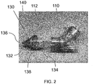
- FIGS. 1-4 illustrate an exemplary system 100 for providing respiratory therapy to a patient in accordance with aspects of the present invention.
- system 100 includes a nebulizer 110, an adaptor 130, and a nasal cannula 150. Additional details of system 100 will be described herein.
- Nebulizer 110 is operable to generate an aerosolized medicament.
- Nebulizer 110 includes an aerosol generator (not shown) that aerosolizes a medicament contained within nebulizer 110.
- nebulizer 110 also includes a nebulizer outlet port 112 at the bottom of nebulizer 110.
- nebulizer 110 may use an electrical signal to draw fluid into a vibratory aerosolization element (not shown), to generate an aerosol mist in the form of a low velocity cloud of aerosolized medicament.
- the cloud of aerosolized medicament exits nebulizer 110 by passing through nebulizer outlet port 112.
- nebulizer 110 is the AERONEB ® Solo nebulizer, available from Aerogen, Ltd of Galway, Ireland.
- AERONEB ® Solo nebulizer available from Aerogen, Ltd of Galway, Ireland.
- any conventional nebulizer may be used (with corresponding modifications to the size of the nebulizer coupling port of the adaptor), as would be understood by one of ordinary skill in the art from the description herein.
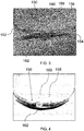
- Adaptor 130 is couplable to nebulizer 110. As shown in FIG. 2 , adaptor 130 has an adaptor body 132 defining a mixing chamber. Adaptor 130 includes a nebulizer coupling port 134 and an adaptor outlet port 136. Ports 134 and 136 each open into the mixing chamber defined by adaptor body 132. Nebulizer coupling port 134 of adaptor 130 is configured to be coupled to the outlet port 112 of nebulizer 110 (e.g., by friction fit) in order to receive the cloud of aerosolized medicament. Accordingly, the size of nebulizer coupling port 134 may be selected based on the nebulizer 110 used with system 100. The cloud of aerosolized medicament may then pass into the adaptor body 132. Suitable materials for forming adaptor 130 will be known to one of ordinary skill in the art from the description herein.
- Adaptor 130 may desirably have an adaptor outlet port 136 that is limited in size (e.g., less than 1 mm in diameter).
- Adapter outlet port 136 may have a cross-sectional area less than the cross-sectional area of nebulizer coupling port 134.
- Adaptor outlet port 136 may be configured to be attached to a corresponding attachment device of nasal cannula 150, as will be described in greater detail below.
- adaptor body 132 is an approximately cone-shaped body between nebulizer coupling port 134 and adaptor outlet port 136, as shown in FIG. 2 .
- the cone-shaped body may further include a cylindrical portion extending therefrom for attachment to nebulizer outlet port 112.
- Adaptor body 132 is shaped such that adaptor outlet port 136 has a cross-sectional area less than that of nebulizer coupling port 134. This feature may be desirable in order to precisely regulate the flow of aerosolized medicament from adaptor 130.
- Adaptor 130 may comprise a vent hole 138.
- Vent hole 138 is positioned between nebulizer coupling port 134 and adaptor outlet port 136. Vent hole 138 enables venting of pressure that may build up within adaptor 130 during use of system 100. This may be desirable when the flow of aerosolized medicament from nebulizer 110 into adaptor 130 is in excess of the flow of aerosolized medicament out of adaptor outlet port 136.
- adaptor 130 may further comprise a shielding portion 140. Shielding portion 140 is positioned to prevent obstruction of vent hole 138 so that adaptor 130 can function normally during use. Shielding portion 140 can be integrally formed with adaptor body 132, as shown in FIG. 2 .
- Adaptor 130 may desirably be removably attached to nebulizer 110, as shown in FIG. 2 .
- nebulizer coupling port 134 is configured to be slidably received within nebulizer outlet port 112.
- Removably attaching adaptor 130 to nebulizer 110 may enable multiple adaptors 130 having differently sized adaptor outlet ports 136 to be used with system 100. This may be desirable to change the amount of aerosolized medicament provided during use of system 100.
- adaptor 130 is illustrated as having a single adaptor outlet port 136, it will be understood by one of ordinary skill in the art that the invention is not so limited.
- Adaptor 130 may be designed to include a pair of spaced apart adapter outlet ports 136. The spacing between the pair of adaptor outlet ports 136 may be selected to correspond to the spacing between nasal prongs of an associated nasal cannula, so that the aerosolized medicament may be provided through both nares of the patient (instead of via a single nare).
- Nasal cannula 150 is configured to provide a flow of breathing gas from a breathing gas source to the patient.
- nasal cannula 150 comprises a first supply tube 152, a second supply tube 154, and a cannula body 156, as shown in FIGS. 3 and 4 .
- Supply tubes 152 and 154 are elongated, hollow lumens.
- Supply tubes 152 and 154 may be connected to a connector (not shown) in order to receive breathing gas from a breathing gas source. Thereby, supply tubes 152 and 154 enable fluid communication between the breathing gas source and cannula body 156.
- Cannula body 156 is coupled to the ends of supply tubes 152 and 154. As shown in FIGS. 3 and 4 , cannula body 156 includes nasal prongs 158 and 160 extending from cannula body 156. When nasal cannula 150 is secured to the patient, nasal prongs 158 and 160 are positioned within respective nares of the patient. Nasal prongs 158 and 160 provide the flow of breathing gas received from supply tubes 152 and 154 to the patient.
- Nasal cannula 150 may further comprise an attachment device 162. As shown in FIGS. 3 and 4 , attachment device 162 is provided on cannula body 156 and positioned adjacent one of the nasal prongs 160. In one embodiment, attachment device 162 is positioned directly adjacent the base of nasal prong 160.
- Attachment device 162 is configured to secure adaptor outlet port 136 adjacent an outlet of nasal prong 160.
- attachment device 162 may position adaptor outlet port 136 substantially within or directly below a nare of the patient when nasal cannula 150 is secured to the patient, on an anterior surface of cannula body 156.
- the aerosolized medicament from nebulizer 110 may be provided to the patient along with the flow of breathing gas from nasal cannula 150 using the slipstream effect.
- the aerosolized medicament may desirably be drawn into the breathing gas slipstream, and thereby inhaled by the patient along with the breathing gas. It may be desirably that adaptor outlet port 136 be positioned outside of the nare of the patient (i.e. directly below the nare), in order to avoid obstructing the patient's nare during use.
- nasal cannula 150 having a shorter nasal prong includes one nasal prong 160 that is shorter than the other nasal prong 158, e.g., approximately half as long.
- a suitable length for shorter nasal prong 160 may be between approximately 3-4 mm for infant and pediatric patients, and between approximately 6-7 mm for adult patients.
- Attachment device 162 is positioned directly adjacent the base of the shorter nasal prong 160.
- Attachment device 162 may comprise a loop configured to receive a portion of adaptor 130 therethrough, as shown in FIGS. 1 and 3 .
- adaptor 130 may comprise a protrusion adapted to be received within the attachment device 162 of the nasal cannula 150.
- adaptor 130 comprises a protrusion (defining adaptor outlet port 136) which may be received in the loop during use of system 100.
- attachment device 162 is shown in FIG. 3 as a loop, it will be understood by one of ordinary skill in the art that the invention is not so limited.
- Attachment device 162 may comprise any structure adapted to secure a portion of adaptor 130 to nasal cannula 150 in the proper position (i.e., in a position which allows slipstreaming of the aerosolized medicament within the flow of breathing gas from nasal cannula 150).
- Suitable structures include, for example, U-clips, hook-and-loop fasteners, or magnets.
- Other suitable attachment devices 162 will be known to one of ordinary skill from the description herein.
- nasal cannula 150 does not include an attachment device, and/or adaptor 130 does not include a protrusion for coupling to the attachment device.
- adaptor 130 may be held in place during use.
- Adaptor body 132 may comprise one or more structures (such as wings, grips, depressions, or other features) that facilitate proper positioning and holding of adaptor 130 by the user. Suitable structures for assisting the user in holding or positioning adaptor 130 will be known to one of ordinary skill in the art from the description herein.
- System 100 is not limited to the above components, but may include alternative or additional components, as would be understood by one of ordinary skill in the art.
- system 100 may further comprise a source of breathing gas.
- the source of breathing gas provides breathing gas for inhalation by a user of system.
- the source may desirably generate heated and humidified breathing gas.
- the breathing gas source is the Vapotherm 2000i, the Vapotherm Precision Flow, the Vapotherm Flowrest System, or the Vapotherm Careflow system provided by Vapotherm, Inc of Stevensville, Maryland, USA.
- Other suitable breathing gas sources will be known to one of ordinary skill in the art from the description herein.
- the source of breathing gas may be coupled to supply tubes 152 and 154 of nasal cannula 150, in order to provide the breathing gas to the patient.
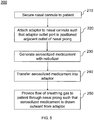
- FIG. 5 is a flowchart illustrating an exemplary method 200 for providing respiratory therapy in accordance with aspects of the present disclosure.
- Method 200 may be implemented using the exemplary system 100 described above.
- method 200 includes securing a nasal cannula to the patient, attaching an adaptor to the nasal cannula, generating an aerosolized medicament, transferring the aerosolized medicament to the adaptor, and providing a flow of breathing gas to the patient. Additional details of method 200 will be described herein with reference to system 100.
- a nasal cannula is secured to the patient.
- nasal cannula 150 is secured to the patient.
- nasal prongs 158 and 160 are positioned within respective nares of the patient.
- an adaptor is attached to the nasal cannula.
- adaptor 130 is attached to nasal cannula 150 using attachment device 162.
- Adaptor 130 is attached to nasal cannula 150 such that adaptor outlet port 136 is positioned adjacent an outlet of nasal prong 160 of nasal cannula 150.
- attachment device 162 may position adaptor outlet port 136 substantially within or directly below a nare of the patient when nasal cannula 150 is secured to the patient in step 210.
- attachment device 162 may comprise a loop
- adaptor 130 may comprise a protrusion adapted to be received within the loop.
- step 220 may comprise positioning a protrusion of the adaptor 130 within the loop.
- nasal cannula 150 may include one nasal prong 160 that is shorter than the other nasal prong 158. Accordingly, step 220 may comprise attaching adaptor 130 to nasal cannula 150 such that adaptor outlet port 136 is positioned adjacent an outlet of the shorter nasal prong 160, in order to optimize slipstreaming of the aerosolized medicament.
- step 230 an aerosolized medicament is generated.
- nebulizer 110 generates an aerosolized medicament, substantially as described above.
- the aerosolized medicament is transferred into the adaptor.
- the aerosolized medicament generated by nebulizer 110 passes out of nebulizer 110 through the nebulizer output port 112.
- Adaptor 130 is coupled to nebulizer 110 such that the aerosolized medicament passes in through nebulizer coupling port 134 into adaptor body 132 of adaptor 130.
- a flow of breathing gas is provided to the patient.
- a flow of breathing gas is provided to the patient through nasal prongs 158 and 160 of nasal cannula 150. Due to the positioning of adaptor outlet port 136 within attachment device 162, the flow of breathing gas causes the aerosolized medicament within adaptor 130 to be drawn outward from adaptor 130 through adaptor outlet port 136 and inhaled by the patient with the flow of breathing gas.
- step 250 uses the slipstream effect to entrain the aerosolized medicament in the flow of breathing gas.
- the slipstreaming effect may be enhanced where adaptor outlet port 136 has a cross-sectional area less than that of nebulizer coupling port 134.
- Method 200 is not limited to the above steps, but may include alternative or additional steps, as would be understood by one of ordinary skill in the art.
- adaptor 130 may be removably attachable to nebulizer 110, as described above with respect to system 100. Accordingly, method 200 may include the step of removably attaching adaptor 130 to nebulizer 110.
- adaptor 130 may comprise a vent hole 138 for enabling release of pressure from within adaptor 130.
- method 200 may include the step of venting a portion of the aerosolized medicament from adaptor 130 using vent hole 138.
- adaptor 130 may comprise a drainage port, as described in greater detail below. Accordingly, method 200 may include the step of draining a liquid medicament from adaptor 130 via the drainage port. Where the system further comprises a syringe, the draining step may comprise withdrawing the liquid medicament from the adaptor with a syringe.
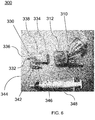
- FIG. 6 illustrates another exemplary system 300 for providing respiratory therapy to a patient in accordance with aspects of the present invention.
- system 300 includes a nebulizer 310 and an adaptor 330. Additional details of system 300 will be described herein.
- Nebulizer 310 is operable to generate an aerosolized medicament. As shown in FIG. 6 , nebulizer 310 includes a nebulizer outlet port 312 at the bottom of nebulizer 310. Nebulizer 310 may be a nebulizer substantially as described above with respect to nebulizer 110.
- Adaptor 330 is couplable to nebulizer 310. As shown in FIG. 6 , adaptor 330 has an adaptor body 332 defining a mixing chamber. Adaptor 330 includes a nebulizer coupling port 334 and an adaptor outlet port 336. Ports 334 and 336 each open into the mixing chamber defined by adaptor body 332. Adaptor 330 may include any of the features described above with respect to adaptor 130. Nebulizer coupling port 334 of adaptor 330 is configured to be coupled to the outlet port 312 of nebulizer 310 (e.g., by friction fit) in order to receive the cloud of aerosolized medicament. Adaptor 330 may include any of the features described above with respect to adaptor 130.
- Adaptor 330 further comprises a drainage port 342.
- Drainage port 342 enables drainage of liquid medicament from adaptor body 332.
- adaptor 330 may accumulate excess liquid medicament within adaptor body 332 during use. This excess liquid medicament may interfere with regular operation of system 300. Accordingly, adaptor 330 is provided with drainage port 342 to enable drainage of this excess liquid medicament, and regular operation of system 300.
- drainage port 342 comprises an elbow-shaped lumen extending outwardly from adaptor body 332, as shown in FIG. 6 .
- the elbow-shaped lumen has a first end 344 affixed to adaptor body 332 and a second end 346 distal from adaptor body 332.
- Distal end 346 extends in the direction of nebulizer coupling port 334 and away from adaptor outlet port 336. This enables coupling distal end 346 to a syringe 348 without interfering with use of system 300.
- drainage port 342 is illustrated as an elbow-shaped lumen, it will be understood by one of ordinary skill in the art that it is not so limited. Drainage port 342 could for example be a straight lumen, or could have any other desirable shape. Additionally, while drainage port 342 is illustrated as substantially rigid, it will be understood by one of ordinary skill in the art that drainage port 342 could be formed from a flexible material.
- system 300 further comprises syringe 348.
- Syringe 348 is adapted to be coupled to distal end 346 of drainage port 342.
- Syringe 348 is configured to withdrawn liquid medicament from adaptor body 332 via drainage port 342.
- syringe 348 may include a plunger which can be pulled outward by a user of system 300 in order to withdraw the liquid medicament.
- the liquid withdrawn by syringe 348 may additionally be reused to generate aerosolized medicament with nebulizer 310.
- Suitable syringes for use as syringe 348 will be known to one of ordinary skill in the art from the description herein. It will be understood by one of ordinary skill in the art that other objects may be used to facilitate withdrawing liquid medicament from adaptor body 332 without departing from the invention.
- Adaptor body 332 may be an approximately cone-shaped body between nebulizer coupling port 334 and adaptor outlet port 336, as shown in FIG. 6 .
- the cone-shaped body may further include a cylindrical portion extending therefrom for attachment to nebulizer outlet port 312.
- drainage port 342 is formed in the cone-shaped body.
- drainage port 342 is formed on a lower portion of adaptor body 332, to enable gravity to assist in drainage of adaptor body 332.
- Adaptor 330 may comprise a vent hole 338 positioned between nebulizer coupling port 334 and adaptor outlet port 336. Drainage port 342 may be formed on an opposite side of adaptor body from vent hole 338.
- System 300 may further include a nasal cannula configured to provide a flow of breathing gas from a breathing gas source to a patient.
- system 300 includes a nasal cannula substantially as described above with respect to nasal cannula 350.
Landscapes
- Health & Medical Sciences (AREA)
- Pulmonology (AREA)
- Emergency Medicine (AREA)
- Life Sciences & Earth Sciences (AREA)
- General Health & Medical Sciences (AREA)
- Biomedical Technology (AREA)
- Heart & Thoracic Surgery (AREA)
- Hematology (AREA)
- Engineering & Computer Science (AREA)
- Animal Behavior & Ethology (AREA)
- Anesthesiology (AREA)
- Public Health (AREA)
- Veterinary Medicine (AREA)
- Otolaryngology (AREA)
- Infusion, Injection, And Reservoir Apparatuses (AREA)
- Medicinal Preparation (AREA)
- Pharmaceuticals Containing Other Organic And Inorganic Compounds (AREA)
Description
- The present invention relates generally to respiratory therapy, and more particularly to systems for providing respiratory therapy.
- Patients with respiratory ailments may be administered supplemental breathing gases, such as oxygen, for example, to aid in respiration. These breathing gases are typically provided from a breathing gas supply, such as an oxygen tank. A delivery device, such as a nasal cannula, may be coupled to the breathing gas supply and inserted into a patient's nasal passages for delivery of the breathing gas to the patient for inhalation.
- Separately, respiratory medications may be administered through inhalation directly to the patient's lungs. These respiratory medications may be aerosolized by a nebulizer in order to generate small particles of the medication, which facilitate distribution throughout the patient's lungs during inhalation. Conventional nebulizers draw liquid medicament from a liquid reservoir to form a nebulized aerosol for inhalation.Document
US 2010/089395 A1 in particular discloses a system connecting a nebulizer and a nasal cannula for providing respiratory therapy to a patient. - Aspects of the present invention are directed to systems for respiratory therapy.
- In accordance with one aspect of the present invention, a system for providing respiratory therapy to a patient is disclosed. The system comprises a nebulizer, an adaptor, and a nasal cannula. The nebulizer has a nebulizer outlet port. The nebulizer is operable to generate an aerosolized medicament and pass the aerosolized medicament through the nebulizer outlet port. The adaptor has an adaptor body, a nebulizer coupling port, and an adaptor outlet port. The nebulizer coupling port of the adaptor is configured to be coupled to the nebulizer outlet port of the nebulizer. The nasal cannula is configured to provide a flow of breathing gas from a breathing gas source to the patient. The nasal cannula comprises at least one nasal prong and an attachment device positioned adjacent the at least one nasal prong. The attachment device is configured to secure the adaptor outlet port adjacent an outlet of the nasal prong.
- A method of providing respiratory therapy to a patient is disclosed. The method comprises securing a nasal cannula to the patient, attaching an adaptor to the nasal cannula using an attachment device such that an adaptor outlet port of the adaptor is positioned adjacent an outlet of a nasal prong of the nasal cannula, generating an aerosolized medicament with a nebulizer, transferring the aerosolized medicament into the adaptor through a nebulizer coupling port of the adaptor, and providing a flow of breathing gas to the patient through the nasal prong such that the aerosolized medicament is drawn outward from the adaptor through the adaptor outlet port and inhaled by the patient with the flow of breathing gas.
- The invention is best understood from the following detailed description when read in connection with the accompanying drawings, with like elements having the same reference numerals. When a plurality of similar elements are present, a single reference numeral may be assigned to the plurality of similar elements with a small letter designation referring to specific elements. When referring to the elements collectively or to a non-specific one or more of the elements, the small letter designation may be dropped. According to common practice, the various features of the drawings are not drawn to scale, unless otherwise indicated. On the contrary, the dimensions of the various features may be expanded or reduced for clarity. Included in the drawings are the following figures:
-
FIG. 1 is an image illustrating an exemplary system for providing respiratory therapy in accordance with aspects of the present invention; -
FIG. 2 is an image illustrating an exemplary adaptor of the system ofFIG. 1 ; -
FIGS. 3 and 4 are images illustrating an exemplary nasal cannula of the system ofFIG. 1 ; -
FIG. 5 is a flowchart illustrating an exemplary method for providing respiratory therapy in accordance with aspects of the present disclosure; -
FIG. 6 is an image illustrating another exemplary system for providing respiratory therapy in accordance with aspects of the present invention. - Embodiments of the present invention are directed to systems for providing respiratory therapy to a patient. These exemplary embodiments may be particularly suitable for providing an aerosolized medicament to a patient via a breathing device, such as a nasal cannula. Suitable medicaments for use with the disclosed systems will be known to one of ordinary skill in the art. Additionally, while the exemplary embodiments are described herein for use in conjunction with a nasal cannula, it will be understood that other breathing devices may be used without departing from the scope of the invention as defined by the appended claims.
- As a general overview, the disclosed embodiments of the present invention are usable to provide aerosolized medicament along with a flow of breathing gas to a patient. The embodiments operate by using the slipstream effect to entrain the aerosolized medicament in the flow of breathing gas. As the flow of breathing gas leaves a breathing device (such as a nasal cannula) for inhalation by the patient, the aerosolized medicament is drawn into the breathing gas slipstream, and thereby inhaled by the patient along with the breathing gas.
- Referring now to the drawings,
FIGS. 1-4 illustrate anexemplary system 100 for providing respiratory therapy to a patient in accordance with aspects of the present invention. Generally,system 100 includes anebulizer 110, anadaptor 130, and anasal cannula 150. Additional details ofsystem 100 will be described herein. - Nebulizer 110 is operable to generate an aerosolized medicament. Nebulizer 110 includes an aerosol generator (not shown) that aerosolizes a medicament contained within
nebulizer 110. As shown inFIG. 2 ,nebulizer 110 also includes anebulizer outlet port 112 at the bottom ofnebulizer 110. For example,nebulizer 110 may use an electrical signal to draw fluid into a vibratory aerosolization element (not shown), to generate an aerosol mist in the form of a low velocity cloud of aerosolized medicament. The cloud of aerosolizedmedicament exits nebulizer 110 by passing throughnebulizer outlet port 112. In an exemplary embodiment,nebulizer 110 is the AERONEB® Solo nebulizer, available from Aerogen, Ltd of Galway, Ireland. However, essentially any conventional nebulizer may be used (with corresponding modifications to the size of the nebulizer coupling port of the adaptor), as would be understood by one of ordinary skill in the art from the description herein. -
Adaptor 130 is couplable tonebulizer 110. As shown inFIG. 2 ,adaptor 130 has anadaptor body 132 defining a mixing chamber. Adaptor 130 includes anebulizer coupling port 134 and anadaptor outlet port 136.Ports adaptor body 132.Nebulizer coupling port 134 ofadaptor 130 is configured to be coupled to theoutlet port 112 of nebulizer 110 (e.g., by friction fit) in order to receive the cloud of aerosolized medicament. Accordingly, the size ofnebulizer coupling port 134 may be selected based on thenebulizer 110 used withsystem 100. The cloud of aerosolized medicament may then pass into theadaptor body 132. Suitable materials for formingadaptor 130 will be known to one of ordinary skill in the art from the description herein. -
Adaptor 130 may desirably have anadaptor outlet port 136 that is limited in size (e.g., less than 1 mm in diameter).Adapter outlet port 136 may have a cross-sectional area less than the cross-sectional area ofnebulizer coupling port 134.Adaptor outlet port 136 may be configured to be attached to a corresponding attachment device ofnasal cannula 150, as will be described in greater detail below. - In an exemplary embodiment,
adaptor body 132 is an approximately cone-shaped body betweennebulizer coupling port 134 andadaptor outlet port 136, as shown inFIG. 2 . The cone-shaped body may further include a cylindrical portion extending therefrom for attachment tonebulizer outlet port 112.Adaptor body 132 is shaped such thatadaptor outlet port 136 has a cross-sectional area less than that ofnebulizer coupling port 134. This feature may be desirable in order to precisely regulate the flow of aerosolized medicament fromadaptor 130. -
Adaptor 130 may comprise avent hole 138.Vent hole 138 is positioned betweennebulizer coupling port 134 andadaptor outlet port 136.Vent hole 138 enables venting of pressure that may build up withinadaptor 130 during use ofsystem 100. This may be desirable when the flow of aerosolized medicament fromnebulizer 110 intoadaptor 130 is in excess of the flow of aerosolized medicament out ofadaptor outlet port 136. In this embodiment,adaptor 130 may further comprise a shieldingportion 140.Shielding portion 140 is positioned to prevent obstruction ofvent hole 138 so thatadaptor 130 can function normally during use.Shielding portion 140 can be integrally formed withadaptor body 132, as shown inFIG. 2 . -
Adaptor 130 may desirably be removably attached tonebulizer 110, as shown inFIG. 2 . In an exemplary embodiment,nebulizer coupling port 134 is configured to be slidably received withinnebulizer outlet port 112.Removably attaching adaptor 130 tonebulizer 110 may enablemultiple adaptors 130 having differently sizedadaptor outlet ports 136 to be used withsystem 100. This may be desirable to change the amount of aerosolized medicament provided during use ofsystem 100. - While
adaptor 130 is illustrated as having a singleadaptor outlet port 136, it will be understood by one of ordinary skill in the art that the invention is not so limited.Adaptor 130 may be designed to include a pair of spaced apartadapter outlet ports 136. The spacing between the pair ofadaptor outlet ports 136 may be selected to correspond to the spacing between nasal prongs of an associated nasal cannula, so that the aerosolized medicament may be provided through both nares of the patient (instead of via a single nare). -
Nasal cannula 150 is configured to provide a flow of breathing gas from a breathing gas source to the patient. In an exemplary embodiment,nasal cannula 150 comprises afirst supply tube 152, asecond supply tube 154, and acannula body 156, as shown inFIGS. 3 and 4 .Supply tubes Supply tubes supply tubes cannula body 156. -
Cannula body 156 is coupled to the ends ofsupply tubes FIGS. 3 and 4 ,cannula body 156 includesnasal prongs cannula body 156. Whennasal cannula 150 is secured to the patient,nasal prongs Nasal prongs supply tubes -
Nasal cannula 150 may further comprise anattachment device 162. As shown inFIGS. 3 and 4 ,attachment device 162 is provided oncannula body 156 and positioned adjacent one of thenasal prongs 160. In one embodiment,attachment device 162 is positioned directly adjacent the base ofnasal prong 160. -
Attachment device 162 is configured to secureadaptor outlet port 136 adjacent an outlet ofnasal prong 160. In particular,attachment device 162 may positionadaptor outlet port 136 substantially within or directly below a nare of the patient whennasal cannula 150 is secured to the patient, on an anterior surface ofcannula body 156. In this way, the aerosolized medicament fromnebulizer 110 may be provided to the patient along with the flow of breathing gas fromnasal cannula 150 using the slipstream effect. Whenadaptor outlet port 136 is secured byattachment device 162, the aerosolized medicament may desirably be drawn into the breathing gas slipstream, and thereby inhaled by the patient along with the breathing gas. It may be desirably thatadaptor outlet port 136 be positioned outside of the nare of the patient (i.e. directly below the nare), in order to avoid obstructing the patient's nare during use. - In one embodiment, the above-described slipstreaming effect may be increased through the use of a
nasal cannula 150 having a shorter nasal prong. As shown inFIGS. 3 and 4 ,nasal cannula 150 includes onenasal prong 160 that is shorter than the othernasal prong 158, e.g., approximately half as long. A suitable length for shorternasal prong 160 may be between approximately 3-4 mm for infant and pediatric patients, and between approximately 6-7 mm for adult patients.Attachment device 162 is positioned directly adjacent the base of the shorternasal prong 160. The use of anasal cannula 150 having this design enablessystem 100 to have onenasal prong 158 optimized for the delivery of breathing gas and onenasal prong 160 optimized for slipstreaming aerosolized medicament. -
Attachment device 162 may comprise a loop configured to receive a portion ofadaptor 130 therethrough, as shown inFIGS. 1 and3 . Correspondingly,adaptor 130 may comprise a protrusion adapted to be received within theattachment device 162 of thenasal cannula 150. As shown inFIGS. 1 and2 ,adaptor 130 comprises a protrusion (defining adaptor outlet port 136) which may be received in the loop during use ofsystem 100. - While
attachment device 162 is shown inFIG. 3 as a loop, it will be understood by one of ordinary skill in the art that the invention is not so limited.Attachment device 162 may comprise any structure adapted to secure a portion ofadaptor 130 tonasal cannula 150 in the proper position (i.e., in a position which allows slipstreaming of the aerosolized medicament within the flow of breathing gas from nasal cannula 150). Suitable structures include, for example, U-clips, hook-and-loop fasteners, or magnets. Othersuitable attachment devices 162 will be known to one of ordinary skill from the description herein. - In an alternative embodiment,
nasal cannula 150 does not include an attachment device, and/oradaptor 130 does not include a protrusion for coupling to the attachment device. In this embodiment,adaptor 130 may be held in place during use.Adaptor body 132 may comprise one or more structures (such as wings, grips, depressions, or other features) that facilitate proper positioning and holding ofadaptor 130 by the user. Suitable structures for assisting the user in holding orpositioning adaptor 130 will be known to one of ordinary skill in the art from the description herein. -
System 100 is not limited to the above components, but may include alternative or additional components, as would be understood by one of ordinary skill in the art. - For one example,
system 100 may further comprise a source of breathing gas. The source of breathing gas provides breathing gas for inhalation by a user of system. The source may desirably generate heated and humidified breathing gas. In an exemplary embodiment, the breathing gas source is the Vapotherm 2000i, the Vapotherm Precision Flow, the Vapotherm Flowrest System, or the Vapotherm Careflow system provided by Vapotherm, Inc of Stevensville, Maryland, USA. Other suitable breathing gas sources will be known to one of ordinary skill in the art from the description herein. The source of breathing gas may be coupled to supplytubes nasal cannula 150, in order to provide the breathing gas to the patient. -
FIG. 5 is a flowchart illustrating anexemplary method 200 for providing respiratory therapy in accordance with aspects of the present disclosure.Method 200 may be implemented using theexemplary system 100 described above. Generally,method 200 includes securing a nasal cannula to the patient, attaching an adaptor to the nasal cannula, generating an aerosolized medicament, transferring the aerosolized medicament to the adaptor, and providing a flow of breathing gas to the patient. Additional details ofmethod 200 will be described herein with reference tosystem 100. - In
step 210, a nasal cannula is secured to the patient. In an exemplary embodiment,nasal cannula 150 is secured to the patient. Whennasal cannula 150 is secured to the patient,nasal prongs - In
step 220, an adaptor is attached to the nasal cannula. In an exemplary embodiment,adaptor 130 is attached tonasal cannula 150 usingattachment device 162.Adaptor 130 is attached tonasal cannula 150 such thatadaptor outlet port 136 is positioned adjacent an outlet ofnasal prong 160 ofnasal cannula 150. In particular,attachment device 162 may positionadaptor outlet port 136 substantially within or directly below a nare of the patient whennasal cannula 150 is secured to the patient instep 210. - As set forth above,
attachment device 162 may comprise a loop, andadaptor 130 may comprise a protrusion adapted to be received within the loop. Accordingly, step 220 may comprise positioning a protrusion of theadaptor 130 within the loop. - Additionally, as set forth above,
nasal cannula 150 may include onenasal prong 160 that is shorter than the othernasal prong 158. Accordingly, step 220 may comprise attachingadaptor 130 tonasal cannula 150 such thatadaptor outlet port 136 is positioned adjacent an outlet of the shorternasal prong 160, in order to optimize slipstreaming of the aerosolized medicament. - In
step 230, an aerosolized medicament is generated. In an exemplary embodiment,nebulizer 110 generates an aerosolized medicament, substantially as described above. - In
step 240, the aerosolized medicament is transferred into the adaptor. In an exemplary embodiment, the aerosolized medicament generated bynebulizer 110 passes out ofnebulizer 110 through thenebulizer output port 112.Adaptor 130 is coupled tonebulizer 110 such that the aerosolized medicament passes in throughnebulizer coupling port 134 intoadaptor body 132 ofadaptor 130. - In
step 250, a flow of breathing gas is provided to the patient. In an exemplary embodiment, a flow of breathing gas is provided to the patient throughnasal prongs nasal cannula 150. Due to the positioning ofadaptor outlet port 136 withinattachment device 162, the flow of breathing gas causes the aerosolized medicament withinadaptor 130 to be drawn outward fromadaptor 130 throughadaptor outlet port 136 and inhaled by the patient with the flow of breathing gas. - Thereby, step 250 uses the slipstream effect to entrain the aerosolized medicament in the flow of breathing gas. As set forth above, the slipstreaming effect may be enhanced where
adaptor outlet port 136 has a cross-sectional area less than that ofnebulizer coupling port 134. -
Method 200 is not limited to the above steps, but may include alternative or additional steps, as would be understood by one of ordinary skill in the art. - For one example,
adaptor 130 may be removably attachable tonebulizer 110, as described above with respect tosystem 100. Accordingly,method 200 may include the step of removably attachingadaptor 130 tonebulizer 110. - For another example,
adaptor 130 may comprise avent hole 138 for enabling release of pressure from withinadaptor 130. Accordingly,method 200 may include the step of venting a portion of the aerosolized medicament fromadaptor 130 usingvent hole 138. - For yet another example,
adaptor 130 may comprise a drainage port, as described in greater detail below. Accordingly,method 200 may include the step of draining a liquid medicament fromadaptor 130 via the drainage port. Where the system further comprises a syringe, the draining step may comprise withdrawing the liquid medicament from the adaptor with a syringe. -
FIG. 6 illustrates anotherexemplary system 300 for providing respiratory therapy to a patient in accordance with aspects of the present invention. Generally,system 300 includes anebulizer 310 and anadaptor 330. Additional details ofsystem 300 will be described herein. -
Nebulizer 310 is operable to generate an aerosolized medicament. As shown inFIG. 6 ,nebulizer 310 includes anebulizer outlet port 312 at the bottom ofnebulizer 310.Nebulizer 310 may be a nebulizer substantially as described above with respect tonebulizer 110. -
Adaptor 330 is couplable tonebulizer 310. As shown inFIG. 6 ,adaptor 330 has anadaptor body 332 defining a mixing chamber.Adaptor 330 includes anebulizer coupling port 334 and anadaptor outlet port 336.Ports adaptor body 332.Adaptor 330 may include any of the features described above with respect toadaptor 130.Nebulizer coupling port 334 ofadaptor 330 is configured to be coupled to theoutlet port 312 of nebulizer 310 (e.g., by friction fit) in order to receive the cloud of aerosolized medicament.Adaptor 330 may include any of the features described above with respect toadaptor 130. -
Adaptor 330 further comprises adrainage port 342.Drainage port 342 enables drainage of liquid medicament fromadaptor body 332. In an exemplary embodiment,adaptor 330 may accumulate excess liquid medicament withinadaptor body 332 during use. This excess liquid medicament may interfere with regular operation ofsystem 300. Accordingly,adaptor 330 is provided withdrainage port 342 to enable drainage of this excess liquid medicament, and regular operation ofsystem 300. - In an exemplary embodiment,
drainage port 342 comprises an elbow-shaped lumen extending outwardly fromadaptor body 332, as shown inFIG. 6 . The elbow-shaped lumen has afirst end 344 affixed toadaptor body 332 and asecond end 346 distal fromadaptor body 332.Distal end 346 extends in the direction ofnebulizer coupling port 334 and away fromadaptor outlet port 336. This enables couplingdistal end 346 to asyringe 348 without interfering with use ofsystem 300. Whiledrainage port 342 is illustrated as an elbow-shaped lumen, it will be understood by one of ordinary skill in the art that it is not so limited.Drainage port 342 could for example be a straight lumen, or could have any other desirable shape. Additionally, whiledrainage port 342 is illustrated as substantially rigid, it will be understood by one of ordinary skill in the art thatdrainage port 342 could be formed from a flexible material. - As shown in
FIG. 6 ,system 300 further comprisessyringe 348.Syringe 348 is adapted to be coupled todistal end 346 ofdrainage port 342.Syringe 348 is configured to withdrawn liquid medicament fromadaptor body 332 viadrainage port 342. For example,syringe 348 may include a plunger which can be pulled outward by a user ofsystem 300 in order to withdraw the liquid medicament. The liquid withdrawn bysyringe 348 may additionally be reused to generate aerosolized medicament withnebulizer 310. Suitable syringes for use assyringe 348 will be known to one of ordinary skill in the art from the description herein. It will be understood by one of ordinary skill in the art that other objects may be used to facilitate withdrawing liquid medicament fromadaptor body 332 without departing from the invention. -
Adaptor body 332 may be an approximately cone-shaped body betweennebulizer coupling port 334 andadaptor outlet port 336, as shown inFIG. 6 . The cone-shaped body may further include a cylindrical portion extending therefrom for attachment tonebulizer outlet port 312. In this embodiment,drainage port 342 is formed in the cone-shaped body. Preferably,drainage port 342 is formed on a lower portion ofadaptor body 332, to enable gravity to assist in drainage ofadaptor body 332. -
Adaptor 330 may comprise avent hole 338 positioned betweennebulizer coupling port 334 andadaptor outlet port 336.Drainage port 342 may be formed on an opposite side of adaptor body fromvent hole 338. -
System 300 may further include a nasal cannula configured to provide a flow of breathing gas from a breathing gas source to a patient. In an exemplary embodiment,system 300 includes a nasal cannula substantially as described above with respect to nasal cannula 350. - Although the invention is illustrated and described herein with reference to specific embodiments, the invention is not intended to be limited to the details shown. Rather, various modifications may be made in the details within the scope of the appended claims.
Claims (13)
- A system (100;300) for providing respiratory therapy to a patient comprising:a nebulizer (110;310) having a nebulizer outlet port (112;312), the nebulizer operable to generate an aerosolized medicament and pass the aerosolized medicament through the nebulizer outlet port;an adaptor (130;330) having an adaptor body (132;332), a nebulizer coupling port (134;334), and an adaptor outlet port (136;336), the nebulizer coupling port of the adaptor configured to be coupled to the nebulizer outlet port of the nebulizer;and a nasal cannula (150;350) configured to provide a flow of breathing gas from a breathing gas source to the patient, the nasal cannula comprising at least one nasal prong (158;160) and an attachment device (162) positioned adjacent the at least one nasal prong, the attachment device configured to secure the adaptor outlet port adjacent an outlet of the at least one nasal prong so as to allow the aerosolized medicament to be drawn into the flow of breathing gas slipstream as the flow of breathing gas leaves the nasal cannula,wherein the attachment device is configured to position the adaptor outlet port directly below a nare of the patient when the nasal cannula is secured to the patient.
- The system of claim 1, wherein the adaptor outlet port has a cross-sectional area less than the nebulizer coupling port.
- The system of claim 2, wherein the adaptor body comprises a cone-shaped body (132) extending between the nebulizer coupling port and the adaptor outlet port, the cone-shaped body oriented such that the adaptor outlet port has the cross-sectional area less than the nebulizer coupling port.
- The system of claim 1, wherein the adaptor outlet port comprises a protrusion (136) adapted to be received within the attachment device of the nasal cannula.
- The system of claim 1, wherein the adaptor body comprises a vent hole (138;338) positioned between the nebulizer coupling port and the adaptor outlet port, the vent hole enabling venting of pressure from the adaptor.
- The system of claim 5, wherein the adaptor further comprises a shielding portion (140) positioned adjacent the vent hole, the shielding portion disposed to prevent obstruction of the vent hole.
- The system of claim 1, wherein the adaptor is removably attached to the nebulizer.
- The system of claim 7, wherein the nebulizer coupling port is configured to be slidably received within the nebulizer outlet port.
- The system of claim 1, wherein the at least one nasal prong comprises a pair of nasal prongs (158;160), and the attachment device is positioned directly adjacent a base of one of the pair of nasal prongs.
- The system of claim 9, wherein one nasal prong (160) of the pair of nasal prongs is shorter than the other nasal prong (158) of the pair of nasal prongs.
- The system of claim 1, wherein the attachment device comprises a loop configured to receive a portion of the adaptor therethrough.
- The system of claim 1, wherein the adaptor further comprises a drainage port (342).
- The system of claim 12, wherein the drainage port comprises an elbow-shaped lumen extending outwardly from the adaptor body, preferably wherein an end of the elbow-shaped lumen distal the adaptor body extends in the direction of the nebulizer coupling port, preferably wherein a syringe (348) is adapted to be coupled to the end of the elbow-shaped lumen distal the adaptor body, the syringe configured to withdraw the liquid medicament from the adaptor body.
Priority Applications (2)
| Application Number | Priority Date | Filing Date | Title |
|---|---|---|---|
| EP17166116.8A EP3216475B1 (en) | 2012-01-24 | 2013-01-23 | Systems for providing respiratory therapy |
| EP20186871.8A EP3747488A1 (en) | 2012-01-24 | 2013-01-23 | Systems and methods for providing respiratory therapy |
Applications Claiming Priority (2)
| Application Number | Priority Date | Filing Date | Title |
|---|---|---|---|
| US201261590045P | 2012-01-24 | 2012-01-24 | |
| PCT/US2013/022692 WO2013112545A1 (en) | 2012-01-24 | 2013-01-23 | Systems and methods for providing respiratory therapy |
Related Child Applications (3)
| Application Number | Title | Priority Date | Filing Date |
|---|---|---|---|
| EP20186871.8A Division EP3747488A1 (en) | 2012-01-24 | 2013-01-23 | Systems and methods for providing respiratory therapy |
| EP17166116.8A Division EP3216475B1 (en) | 2012-01-24 | 2013-01-23 | Systems for providing respiratory therapy |
| EP17166116.8A Division-Into EP3216475B1 (en) | 2012-01-24 | 2013-01-23 | Systems for providing respiratory therapy |
Publications (4)
| Publication Number | Publication Date |
|---|---|
| EP2806926A1 EP2806926A1 (en) | 2014-12-03 |
| EP2806926A4 EP2806926A4 (en) | 2015-09-09 |
| EP2806926B1 EP2806926B1 (en) | 2017-05-17 |
| EP2806926B2 true EP2806926B2 (en) | 2019-12-25 |
Family
ID=48796204
Family Applications (3)
| Application Number | Title | Priority Date | Filing Date |
|---|---|---|---|
| EP17166116.8A Active EP3216475B1 (en) | 2012-01-24 | 2013-01-23 | Systems for providing respiratory therapy |
| EP20186871.8A Withdrawn EP3747488A1 (en) | 2012-01-24 | 2013-01-23 | Systems and methods for providing respiratory therapy |
| EP13740914.0A Active EP2806926B2 (en) | 2012-01-24 | 2013-01-23 | Systems for providing respiratory therapy |
Family Applications Before (2)
| Application Number | Title | Priority Date | Filing Date |
|---|---|---|---|
| EP17166116.8A Active EP3216475B1 (en) | 2012-01-24 | 2013-01-23 | Systems for providing respiratory therapy |
| EP20186871.8A Withdrawn EP3747488A1 (en) | 2012-01-24 | 2013-01-23 | Systems and methods for providing respiratory therapy |
Country Status (5)
| Country | Link |
|---|---|
| US (4) | US9333317B2 (en) |
| EP (3) | EP3216475B1 (en) |
| CN (1) | CN204364581U (en) |
| AU (3) | AU2013212314B2 (en) |
| WO (1) | WO2013112545A1 (en) |
Families Citing this family (18)
| Publication number | Priority date | Publication date | Assignee | Title |
|---|---|---|---|---|
| EP3216475B1 (en) * | 2012-01-24 | 2020-07-22 | Vapotherm, Inc. | Systems for providing respiratory therapy |
| DE112014001368T5 (en) | 2013-03-15 | 2016-01-21 | Fisher & Paykel Healthcare Ltd. | Nasal cannula assemblies and relevant parts |
| EP3763409B1 (en) | 2013-08-09 | 2022-02-23 | Fisher & Paykel Healthcare Limited | Asymmetrical nasal delivery elements and fittings for nasal interfaces |
| EP3412327A1 (en) | 2014-06-06 | 2018-12-12 | Vapotherm, Inc. | Heated nebulizer adapter for respiratory therapy |
| EP4364770A3 (en) * | 2015-03-31 | 2024-07-17 | Fisher & Paykel Healthcare Limited | Nasal cannula |
| EP3316950B1 (en) * | 2015-06-30 | 2020-08-05 | Vapotherm, Inc. | Nasal cannula for continuous and simultaneous delivery of aerosolized medicament and high flow therapy |
| AU2017290742B2 (en) | 2016-06-30 | 2021-07-29 | Vapotherm, Inc. | Cannula device for high flow therapy |
| USD870269S1 (en) | 2016-09-14 | 2019-12-17 | Fisher & Paykel Healthcare Limited | Nasal cannula assembly |
| US11027077B2 (en) | 2017-03-23 | 2021-06-08 | Stamford Devices Ltd. | Aerosol delivery system and method |
| AU2018240521B2 (en) * | 2017-03-23 | 2023-06-01 | Stamford Devices Ltd | Retrofit aerosol delivery system and method |
| AU2018327338A1 (en) | 2017-09-08 | 2020-03-19 | Vapotherm, Inc. | Birfurcated cannula device |
| CN107648708B (en) * | 2017-10-30 | 2020-11-06 | 重庆智阖康医疗器械有限公司 | Multifunctional nose-plug laser atomization device |
| TWD192077S (en) * | 2017-12-15 | 2018-08-01 | 微邦科技股份有限公司 | Sprayer |
| CN112368040A (en) | 2018-05-31 | 2021-02-12 | 蒸汽热能公司 | Near machine side atomizer |
| US12102755B2 (en) | 2018-05-31 | 2024-10-01 | Vapotherm, Inc. | Cannula-based vibrating mesh nebulizer |
| US11554236B2 (en) * | 2018-12-24 | 2023-01-17 | Koninklijke Philips N.V. | Patient interface device having magnetic coupling features |
| BR112021026256A2 (en) | 2019-06-28 | 2022-03-03 | Vapotherm Inc | Variable geometry cannula |
| US11878115B2 (en) | 2019-09-26 | 2024-01-23 | Vapotherm, Inc. | Internal cannula mounted nebulizer |
Citations (14)
| Publication number | Priority date | Publication date | Assignee | Title |
|---|---|---|---|---|
| WO1989009565A1 (en) † | 1988-04-15 | 1989-10-19 | Bowe Edwin A | Method and apparatus for inhalation of treating gas and sampling of exhaled gas for quantitative analysis |
| US4912105A (en) † | 1988-06-10 | 1990-03-27 | Rhone-Poulenc Sante | Derivatives of phenothiazine and the compositions which contain them |
| US5584285A (en) † | 1995-06-07 | 1996-12-17 | Salter Labs | Breathing circuit apparatus for a nebulizer |
| US20020053346A1 (en) † | 1998-04-03 | 2002-05-09 | James N. Curti | Nasal cannula |
| WO2003035141A2 (en) † | 2001-10-25 | 2003-05-01 | Worldwide Medical Technologies, Inc. | Nasal cannula |
| EP1317941A2 (en) † | 2001-12-05 | 2003-06-11 | Innomed Technologies, Inc. | Nasal ventilation cannula |
| US20040221846A1 (en) † | 2001-01-04 | 2004-11-11 | Curti James N. | Nasal and oral cannula breathing detection device |
| US20050229929A1 (en) † | 2004-04-20 | 2005-10-20 | Aerogen, Inc. | Aerosol delivery apparatus and method for pressure-assisted breathing systems |
| WO2009078805A1 (en) † | 2007-12-19 | 2009-06-25 | Ventinvent Ab | A nebulising device for use in a cpap-system |
| US20090241948A1 (en) † | 2007-03-28 | 2009-10-01 | Dermot Joseph Clancy | Humidification in breathing circuits |
| WO2009149336A2 (en) † | 2008-06-06 | 2009-12-10 | Salter Labs | Adaptive temperature sensor for breath monitoring device |
| US20110073116A1 (en) † | 2008-02-21 | 2011-03-31 | Harald Genger | Applicators for a Nasal Cannula |
| US20110271962A1 (en) † | 2003-05-30 | 2011-11-10 | Craig Karl White | Breathing assistance apparatus |
| WO2012020004A1 (en) † | 2010-08-09 | 2012-02-16 | Nycomed Gmbh | Device and system for delivery of an aerosol to a patient on ventilatory support |
Family Cites Families (66)
| Publication number | Priority date | Publication date | Assignee | Title |
|---|---|---|---|---|
| US1149010A (en) | 1914-04-28 | 1915-08-03 | Olive I Wilson | Sterilizer. |
| US2485184A (en) * | 1948-05-07 | 1949-10-18 | Premo Pharmaceutical Lab Inc | Nebulizer |
| US3864326A (en) | 1972-05-22 | 1975-02-04 | Robert S Babington | Spraying devices, in particular nebulizing devices |
| US3826255A (en) | 1972-06-22 | 1974-07-30 | Hudson Oxygen Therapy Sales Co | Intermittent positive pressure breathing manifold |
| US3945378A (en) | 1974-03-18 | 1976-03-23 | Paluch Bernard R | Positive pressure breathing circuit |
| DE2451157C3 (en) | 1974-10-28 | 1983-05-19 | Aluminium Norf Gmbh, 4040 Neuss | Process for cleaning exhaust air produced in large quantities during the operation of rolling stands |
| US4177945A (en) | 1978-03-06 | 1979-12-11 | Warner-Lambert Company | Humidifier unit |
| US4852563A (en) * | 1987-06-22 | 1989-08-01 | The Kendall Company | Multifunction connector for a breathing circuit |
| US4832012A (en) | 1987-07-08 | 1989-05-23 | Vortran Medical Technology, Inc. | Intermittent signal actuated nebulizer |
| US4805609A (en) * | 1987-07-17 | 1989-02-21 | Josephine A. Roberts | Pressurized ventilation system for patients |
| US4819625A (en) | 1987-11-12 | 1989-04-11 | Cimco, Inc. | Nebulizer heater |
| US4911157A (en) | 1988-01-07 | 1990-03-27 | Pegasus Research Corporation | Self-regulating, heated nebulizer system |
| US5335656A (en) * | 1988-04-15 | 1994-08-09 | Salter Laboratories | Method and apparatus for inhalation of treating gas and sampling of exhaled gas for quantitative analysis |
| US4951661A (en) | 1988-06-08 | 1990-08-28 | Thayer Medical Corporation | Quick-connect adapter valve for connecting nebulizer and fluid ventilator hose |
| US4915105A (en) | 1988-10-28 | 1990-04-10 | Lee Tien Chu | Miniature respiratory apparatus |
| US5099833A (en) | 1991-02-19 | 1992-03-31 | Baxter International Inc. | High efficiency nebulizer having a flexible reservoir |
| US5226411A (en) | 1991-03-07 | 1993-07-13 | Walter Levine | Aerosol nebulizer heater |
| DE4225928A1 (en) | 1992-08-05 | 1994-02-10 | Ritzau Pari Werk Gmbh Paul | Atomizer device with heating device |
| US5611332A (en) | 1995-03-22 | 1997-03-18 | Bono; Michael | Aerosol inhalation device containing a rain-off chamber |
| US5752511A (en) * | 1996-11-22 | 1998-05-19 | Simmons; Carl J. | Universal medical tube retainer and nasal wall tissue dilator |
| US6328030B1 (en) | 1999-03-12 | 2001-12-11 | Daniel E. Kidwell | Nebulizer for ventilation system |
| US6530370B1 (en) | 1999-09-16 | 2003-03-11 | Instrumentation Corp. | Nebulizer apparatus |
| US6539937B1 (en) | 2000-04-12 | 2003-04-01 | Instrumentarium Corp. | Method of maximizing the mechanical displacement of a piezoelectric nebulizer apparatus |
| US7600511B2 (en) | 2001-11-01 | 2009-10-13 | Novartis Pharma Ag | Apparatus and methods for delivery of medicament to a respiratory system |
| US7971588B2 (en) | 2000-05-05 | 2011-07-05 | Novartis Ag | Methods and systems for operating an aerosol generator |
| US6363932B1 (en) | 2000-07-06 | 2002-04-02 | Clinical Technologies, Inc. | Aerosol enhancement device |
| US6769626B1 (en) | 2000-10-30 | 2004-08-03 | Instrumentarium Corp. | Device and method for detecting and controlling liquid supply to an apparatus discharging liquids |
| JP2003250894A (en) | 2002-02-28 | 2003-09-09 | Metoran:Kk | Breathing circuit and heating cover for breathing circuit |
| US8074649B2 (en) | 2002-07-18 | 2011-12-13 | Aeon Research And Technology, Inc. | Endotracheal tube with feature for delivering aerosolized medication |
| US7204248B2 (en) * | 2002-09-27 | 2007-04-17 | Cook Critical Care Incorporated | Fiberoptic nebulizer |
| US20040237178A1 (en) | 2003-05-27 | 2004-12-02 | Gaspar Landeros | Self-contained on land on water in air protective apparatus for mass protection and mass continuation |
| US9022027B2 (en) | 2004-02-20 | 2015-05-05 | Pneumoflex Systems, Llc | Nebulizer with intra-oral vibrating mesh |
| US20050217667A1 (en) | 2004-03-30 | 2005-10-06 | Sunil Dhuper | Aerosol deliver apparatus IV |
| US7290541B2 (en) * | 2004-04-20 | 2007-11-06 | Aerogen, Inc. | Aerosol delivery apparatus and method for pressure-assisted breathing systems |
| US7946291B2 (en) * | 2004-04-20 | 2011-05-24 | Novartis Ag | Ventilation systems and methods employing aerosol generators |
| US7721734B2 (en) | 2004-05-14 | 2010-05-25 | Carefusion 2200, Inc. | Inhalation apparatus |
| WO2005115520A1 (en) | 2004-05-20 | 2005-12-08 | Discovery Laboratories, Inc. | Methods , systems and devices for noninvasive pulmonary delivery |
| US20060120968A1 (en) | 2004-05-20 | 2006-06-08 | Ralph Niven | Methods, systems and devices for delivery of pulmonary surfactants |
| WO2006026237A1 (en) | 2004-05-20 | 2006-03-09 | Discovery Laboratories, Inc. | Methods, systems and devices for noninvasive pulmonary delivery |
| DE102006006183A1 (en) | 2006-02-10 | 2007-08-16 | Pari GmbH Spezialisten für effektive Inhalation | Inhalation therapy device for use in premature babies and toddlers |
| ES2592274T3 (en) * | 2006-03-30 | 2016-11-29 | Carefusion 2200, Inc. | Nebulizer with flow-based fluid control |
| US20080216841A1 (en) * | 2007-03-08 | 2008-09-11 | Grimes Beverly S | Nasal cannula |
| MX2010003263A (en) | 2007-09-25 | 2010-06-02 | Novartis Ag | Treatment of pulmonary disorders with aerosolized medicaments such as vancomycin. |
| ES2565219T3 (en) | 2008-03-17 | 2016-04-01 | Discovery Laboratories, Inc. | Ventilation circuit adapter and proximal spray management system |
| US8418690B2 (en) * | 2008-09-26 | 2013-04-16 | Stamford Devices Limited | Supplemental oxygen delivery system |
| WO2010091259A2 (en) | 2009-02-06 | 2010-08-12 | Vapotherm, Inc. | Heated nebulizer devices, nebulizer systems, and methods for inhalation therapy |
| CA2811423C (en) | 2010-09-30 | 2019-03-12 | Breathe Technologies, Inc. | Methods, systems and devices for humidifying a respiratory tract |
| US8945605B2 (en) | 2011-06-07 | 2015-02-03 | Parion Sciences, Inc. | Aerosol delivery systems, compositions and methods |
| US8778383B2 (en) | 2011-06-07 | 2014-07-15 | Parion Sciences, Inc. | Methods of treatment |
| EP3216475B1 (en) * | 2012-01-24 | 2020-07-22 | Vapotherm, Inc. | Systems for providing respiratory therapy |
| US20130255670A1 (en) | 2012-04-02 | 2013-10-03 | Lexion Medical, Llc | System and Method for Performing a Surgical Procedure |
| CN109011046B (en) | 2012-04-20 | 2021-10-01 | 艾诺维亚股份有限公司 | Device for delivering a fluid to a target |
| DE202013006445U1 (en) | 2013-07-17 | 2013-08-08 | Dräger Medical GmbH | Ventilation tube unit and kit with breathing tube unit |
| EP3412327A1 (en) | 2014-06-06 | 2018-12-12 | Vapotherm, Inc. | Heated nebulizer adapter for respiratory therapy |
| EP4364770A3 (en) | 2015-03-31 | 2024-07-17 | Fisher & Paykel Healthcare Limited | Nasal cannula |
| EP3316950B1 (en) | 2015-06-30 | 2020-08-05 | Vapotherm, Inc. | Nasal cannula for continuous and simultaneous delivery of aerosolized medicament and high flow therapy |
| WO2017127420A1 (en) | 2016-01-19 | 2017-07-27 | Nektar Therapeutics | Sealed liquid reservoir for a nebulizer |
| WO2017137252A1 (en) | 2016-02-08 | 2017-08-17 | Koninklijke Philips N.V. | An aerosol generator |
| AU2018240521B2 (en) | 2017-03-23 | 2023-06-01 | Stamford Devices Ltd | Retrofit aerosol delivery system and method |
| US11027077B2 (en) | 2017-03-23 | 2021-06-08 | Stamford Devices Ltd. | Aerosol delivery system and method |
| JP7258771B2 (en) | 2017-03-23 | 2023-04-17 | スタムフォード・ディバイセズ・リミテッド | Aerosol delivery device |
| ES2987903T3 (en) | 2017-03-23 | 2024-11-18 | Stamford Devices Ltd | Aerosol delivery system |
| TW201927286A (en) | 2017-12-15 | 2019-07-16 | 義大利商凱西製藥公司 | Pharmaceutical formulation comprising pulmonary surfactant for administration by nebulization |
| CN112368040A (en) | 2018-05-31 | 2021-02-12 | 蒸汽热能公司 | Near machine side atomizer |
| US20200016360A1 (en) | 2018-07-11 | 2020-01-16 | Martin Allan Morris | Low flow adaptor to deliver aerosols via nasal cannula without crashout |
| US12151066B2 (en) | 2019-05-24 | 2024-11-26 | Stamford Devices Ltd. Dangan, IE | Aerosol chamber and interface to optimize inhaled dose with neonatal CPAP device |
-
2013
- 2013-01-23 EP EP17166116.8A patent/EP3216475B1/en active Active
- 2013-01-23 EP EP20186871.8A patent/EP3747488A1/en not_active Withdrawn
- 2013-01-23 CN CN201390000332.9U patent/CN204364581U/en not_active Expired - Lifetime
- 2013-01-23 EP EP13740914.0A patent/EP2806926B2/en active Active
- 2013-01-23 WO PCT/US2013/022692 patent/WO2013112545A1/en not_active Ceased
- 2013-01-23 AU AU2013212314A patent/AU2013212314B2/en not_active Ceased
- 2013-01-24 US US13/749,162 patent/US9333317B2/en active Active
-
2016
- 2016-04-28 US US15/141,492 patent/US10265494B2/en active Active
-
2017
- 2017-10-26 AU AU2017251790A patent/AU2017251790B2/en not_active Ceased
-
2019
- 2019-03-05 US US16/293,329 patent/US11439788B2/en active Active
-
2020
- 2020-02-28 AU AU2020201493A patent/AU2020201493B2/en not_active Ceased
-
2022
- 2022-08-09 US US17/884,155 patent/US12558512B2/en active Active
Patent Citations (15)
| Publication number | Priority date | Publication date | Assignee | Title |
|---|---|---|---|---|
| WO1989009565A1 (en) † | 1988-04-15 | 1989-10-19 | Bowe Edwin A | Method and apparatus for inhalation of treating gas and sampling of exhaled gas for quantitative analysis |
| US4912105A (en) † | 1988-06-10 | 1990-03-27 | Rhone-Poulenc Sante | Derivatives of phenothiazine and the compositions which contain them |
| US5584285A (en) † | 1995-06-07 | 1996-12-17 | Salter Labs | Breathing circuit apparatus for a nebulizer |
| US20020053346A1 (en) † | 1998-04-03 | 2002-05-09 | James N. Curti | Nasal cannula |
| US20040221846A1 (en) † | 2001-01-04 | 2004-11-11 | Curti James N. | Nasal and oral cannula breathing detection device |
| WO2003035141A2 (en) † | 2001-10-25 | 2003-05-01 | Worldwide Medical Technologies, Inc. | Nasal cannula |
| EP1317941A2 (en) † | 2001-12-05 | 2003-06-11 | Innomed Technologies, Inc. | Nasal ventilation cannula |
| US20110271962A1 (en) † | 2003-05-30 | 2011-11-10 | Craig Karl White | Breathing assistance apparatus |
| US20050229929A1 (en) † | 2004-04-20 | 2005-10-20 | Aerogen, Inc. | Aerosol delivery apparatus and method for pressure-assisted breathing systems |
| US20050229926A1 (en) † | 2004-04-20 | 2005-10-20 | Aerogen, Inc. | Method and composition for the treatment of lung surfactant deficiency or dysfunction |
| US20090241948A1 (en) † | 2007-03-28 | 2009-10-01 | Dermot Joseph Clancy | Humidification in breathing circuits |
| WO2009078805A1 (en) † | 2007-12-19 | 2009-06-25 | Ventinvent Ab | A nebulising device for use in a cpap-system |
| US20110073116A1 (en) † | 2008-02-21 | 2011-03-31 | Harald Genger | Applicators for a Nasal Cannula |
| WO2009149336A2 (en) † | 2008-06-06 | 2009-12-10 | Salter Labs | Adaptive temperature sensor for breath monitoring device |
| WO2012020004A1 (en) † | 2010-08-09 | 2012-02-16 | Nycomed Gmbh | Device and system for delivery of an aerosol to a patient on ventilatory support |
Non-Patent Citations (3)
| Title |
|---|
| CAIRO J M ET AL: "Mosby's respiratory care equipment, 9th Ed.", pages: 20,98 † |
| KACMAREK, R. ET AL: "Egan's Fundamentals of Respiratory Care, 11th Ed.", pages: 123 - 124 † |
| SACCI, R.: "Air entrainment masks; Jet mixing is how they work", RESPIRATORY CARE, vol. 24, no. 10, 1979 † |
Also Published As
| Publication number | Publication date |
|---|---|
| AU2013212314B2 (en) | 2017-08-17 |
| WO2013112545A1 (en) | 2013-08-01 |
| EP2806926A4 (en) | 2015-09-09 |
| EP3216475A1 (en) | 2017-09-13 |
| US10265494B2 (en) | 2019-04-23 |
| EP2806926B1 (en) | 2017-05-17 |
| AU2020201493A1 (en) | 2020-03-19 |
| AU2017251790A1 (en) | 2017-11-16 |
| CN204364581U (en) | 2015-06-03 |
| AU2013212314A1 (en) | 2014-08-14 |
| US11439788B2 (en) | 2022-09-13 |
| US20190328993A1 (en) | 2019-10-31 |
| AU2020201493B2 (en) | 2022-03-10 |
| EP2806926A1 (en) | 2014-12-03 |
| US20230211114A1 (en) | 2023-07-06 |
| US9333317B2 (en) | 2016-05-10 |
| US20170014593A1 (en) | 2017-01-19 |
| EP3747488A1 (en) | 2020-12-09 |
| US12558512B2 (en) | 2026-02-24 |
| AU2017251790B2 (en) | 2019-12-05 |
| EP3216475B1 (en) | 2020-07-22 |
| US20130186395A1 (en) | 2013-07-25 |
Similar Documents
| Publication | Publication Date | Title |
|---|---|---|
| US12558512B2 (en) | Systems and methods for providing respiratory therapy | |
| US10905834B2 (en) | Aerosol delivery system | |
| US8915245B2 (en) | Nebulizer systems, apparatus and methods for respiratory therapy | |
| US20250177669A1 (en) | Cannula-based vibrating mesh nebulizer | |
| HK40042530A (en) | Systems and methods for providing respiratory therapy |
Legal Events
| Date | Code | Title | Description |
|---|---|---|---|
| PUAI | Public reference made under article 153(3) epc to a published international application that has entered the european phase |
Free format text: ORIGINAL CODE: 0009012 |
|
| 17P | Request for examination filed |
Effective date: 20140821 |
|
| AK | Designated contracting states |
Kind code of ref document: A1 Designated state(s): AL AT BE BG CH CY CZ DE DK EE ES FI FR GB GR HR HU IE IS IT LI LT LU LV MC MK MT NL NO PL PT RO RS SE SI SK SM TR |
|
| DAX | Request for extension of the european patent (deleted) | ||
| RA4 | Supplementary search report drawn up and despatched (corrected) |
Effective date: 20150807 |
|
| RIC1 | Information provided on ipc code assigned before grant |
Ipc: A61M 11/00 20060101AFI20150803BHEP Ipc: A61M 16/08 20060101ALI20150803BHEP Ipc: A61M 16/06 20060101ALI20150803BHEP |
|
| GRAP | Despatch of communication of intention to grant a patent |
Free format text: ORIGINAL CODE: EPIDOSNIGR1 |
|
| INTG | Intention to grant announced |
Effective date: 20161207 |
|
| GRAS | Grant fee paid |
Free format text: ORIGINAL CODE: EPIDOSNIGR3 |
|
| GRAA | (expected) grant |
Free format text: ORIGINAL CODE: 0009210 |
|
| AK | Designated contracting states |
Kind code of ref document: B1 Designated state(s): AL AT BE BG CH CY CZ DE DK EE ES FI FR GB GR HR HU IE IS IT LI LT LU LV MC MK MT NL NO PL PT RO RS SE SI SK SM TR |
|
| REG | Reference to a national code |
Ref country code: GB Ref legal event code: FG4D |
|
| REG | Reference to a national code |
Ref country code: CH Ref legal event code: EP |
|
| REG | Reference to a national code |
Ref country code: IE Ref legal event code: FG4D |
|
| REG | Reference to a national code |
Ref country code: AT Ref legal event code: REF Ref document number: 893905 Country of ref document: AT Kind code of ref document: T Effective date: 20170615 |
|
| REG | Reference to a national code |
Ref country code: DE Ref legal event code: R096 Ref document number: 602013021271 Country of ref document: DE |
|
| REG | Reference to a national code |
Ref country code: NL Ref legal event code: FP |
|
| RAP2 | Party data changed (patent owner data changed or rights of a patent transferred) |
Owner name: VAPOTHERM, INC. |
|
| REG | Reference to a national code |
Ref country code: LT Ref legal event code: MG4D |
|
| REG | Reference to a national code |
Ref country code: AT Ref legal event code: MK05 Ref document number: 893905 Country of ref document: AT Kind code of ref document: T Effective date: 20170517 |
|
| PG25 | Lapsed in a contracting state [announced via postgrant information from national office to epo] |
Ref country code: LT Free format text: LAPSE BECAUSE OF FAILURE TO SUBMIT A TRANSLATION OF THE DESCRIPTION OR TO PAY THE FEE WITHIN THE PRESCRIBED TIME-LIMIT Effective date: 20170517 Ref country code: ES Free format text: LAPSE BECAUSE OF FAILURE TO SUBMIT A TRANSLATION OF THE DESCRIPTION OR TO PAY THE FEE WITHIN THE PRESCRIBED TIME-LIMIT Effective date: 20170517 Ref country code: NO Free format text: LAPSE BECAUSE OF FAILURE TO SUBMIT A TRANSLATION OF THE DESCRIPTION OR TO PAY THE FEE WITHIN THE PRESCRIBED TIME-LIMIT Effective date: 20170817 Ref country code: GR Free format text: LAPSE BECAUSE OF FAILURE TO SUBMIT A TRANSLATION OF THE DESCRIPTION OR TO PAY THE FEE WITHIN THE PRESCRIBED TIME-LIMIT Effective date: 20170818 Ref country code: HR Free format text: LAPSE BECAUSE OF FAILURE TO SUBMIT A TRANSLATION OF THE DESCRIPTION OR TO PAY THE FEE WITHIN THE PRESCRIBED TIME-LIMIT Effective date: 20170517 Ref country code: AT Free format text: LAPSE BECAUSE OF FAILURE TO SUBMIT A TRANSLATION OF THE DESCRIPTION OR TO PAY THE FEE WITHIN THE PRESCRIBED TIME-LIMIT Effective date: 20170517 Ref country code: FI Free format text: LAPSE BECAUSE OF FAILURE TO SUBMIT A TRANSLATION OF THE DESCRIPTION OR TO PAY THE FEE WITHIN THE PRESCRIBED TIME-LIMIT Effective date: 20170517 |
|
| PG25 | Lapsed in a contracting state [announced via postgrant information from national office to epo] |
Ref country code: BG Free format text: LAPSE BECAUSE OF FAILURE TO SUBMIT A TRANSLATION OF THE DESCRIPTION OR TO PAY THE FEE WITHIN THE PRESCRIBED TIME-LIMIT Effective date: 20170817 Ref country code: LV Free format text: LAPSE BECAUSE OF FAILURE TO SUBMIT A TRANSLATION OF THE DESCRIPTION OR TO PAY THE FEE WITHIN THE PRESCRIBED TIME-LIMIT Effective date: 20170517 Ref country code: SE Free format text: LAPSE BECAUSE OF FAILURE TO SUBMIT A TRANSLATION OF THE DESCRIPTION OR TO PAY THE FEE WITHIN THE PRESCRIBED TIME-LIMIT Effective date: 20170517 Ref country code: PL Free format text: LAPSE BECAUSE OF FAILURE TO SUBMIT A TRANSLATION OF THE DESCRIPTION OR TO PAY THE FEE WITHIN THE PRESCRIBED TIME-LIMIT Effective date: 20170517 Ref country code: RS Free format text: LAPSE BECAUSE OF FAILURE TO SUBMIT A TRANSLATION OF THE DESCRIPTION OR TO PAY THE FEE WITHIN THE PRESCRIBED TIME-LIMIT Effective date: 20170517 Ref country code: IS Free format text: LAPSE BECAUSE OF FAILURE TO SUBMIT A TRANSLATION OF THE DESCRIPTION OR TO PAY THE FEE WITHIN THE PRESCRIBED TIME-LIMIT Effective date: 20170917 |
|
| REG | Reference to a national code |
Ref country code: DE Ref legal event code: R081 Ref document number: 602013021271 Country of ref document: DE Owner name: VAPOTHERM, INC., EXETER, US Free format text: FORMER OWNER: VAPOTHERM, INC., STEVENSVILLE, MD., US |
|
| RAP2 | Party data changed (patent owner data changed or rights of a patent transferred) |
Owner name: VAPOTHERM, INC. |
|
| PG25 | Lapsed in a contracting state [announced via postgrant information from national office to epo] |
Ref country code: SK Free format text: LAPSE BECAUSE OF FAILURE TO SUBMIT A TRANSLATION OF THE DESCRIPTION OR TO PAY THE FEE WITHIN THE PRESCRIBED TIME-LIMIT Effective date: 20170517 Ref country code: RO Free format text: LAPSE BECAUSE OF FAILURE TO SUBMIT A TRANSLATION OF THE DESCRIPTION OR TO PAY THE FEE WITHIN THE PRESCRIBED TIME-LIMIT Effective date: 20170517 Ref country code: DK Free format text: LAPSE BECAUSE OF FAILURE TO SUBMIT A TRANSLATION OF THE DESCRIPTION OR TO PAY THE FEE WITHIN THE PRESCRIBED TIME-LIMIT Effective date: 20170517 Ref country code: CZ Free format text: LAPSE BECAUSE OF FAILURE TO SUBMIT A TRANSLATION OF THE DESCRIPTION OR TO PAY THE FEE WITHIN THE PRESCRIBED TIME-LIMIT Effective date: 20170517 Ref country code: EE Free format text: LAPSE BECAUSE OF FAILURE TO SUBMIT A TRANSLATION OF THE DESCRIPTION OR TO PAY THE FEE WITHIN THE PRESCRIBED TIME-LIMIT Effective date: 20170517 |
|
| REG | Reference to a national code |
Ref country code: DE Ref legal event code: R026 Ref document number: 602013021271 Country of ref document: DE |
|
| PLBI | Opposition filed |
Free format text: ORIGINAL CODE: 0009260 |
|
| PG25 | Lapsed in a contracting state [announced via postgrant information from national office to epo] |
Ref country code: SM Free format text: LAPSE BECAUSE OF FAILURE TO SUBMIT A TRANSLATION OF THE DESCRIPTION OR TO PAY THE FEE WITHIN THE PRESCRIBED TIME-LIMIT Effective date: 20170517 |
|
| PLAX | Notice of opposition and request to file observation + time limit sent |
Free format text: ORIGINAL CODE: EPIDOSNOBS2 |
|
| 26 | Opposition filed |
Opponent name: STAMFORD DEVICES LIMITED Effective date: 20180216 |
|
| RAP2 | Party data changed (patent owner data changed or rights of a patent transferred) |
Owner name: VAPOTHERM, INC. |
|
| PG25 | Lapsed in a contracting state [announced via postgrant information from national office to epo] |
Ref country code: SI Free format text: LAPSE BECAUSE OF FAILURE TO SUBMIT A TRANSLATION OF THE DESCRIPTION OR TO PAY THE FEE WITHIN THE PRESCRIBED TIME-LIMIT Effective date: 20170517 |
|
| REG | Reference to a national code |
Ref country code: FR Ref legal event code: PLFP Year of fee payment: 6 |
|
| PLBB | Reply of patent proprietor to notice(s) of opposition received |
Free format text: ORIGINAL CODE: EPIDOSNOBS3 |
|
| REG | Reference to a national code |
Ref country code: CH Ref legal event code: PL |
|
| PG25 | Lapsed in a contracting state [announced via postgrant information from national office to epo] |
Ref country code: LU Free format text: LAPSE BECAUSE OF NON-PAYMENT OF DUE FEES Effective date: 20180123 |
|
| REG | Reference to a national code |
Ref country code: BE Ref legal event code: MM Effective date: 20180131 |
|
| PG25 | Lapsed in a contracting state [announced via postgrant information from national office to epo] |
Ref country code: BE Free format text: LAPSE BECAUSE OF NON-PAYMENT OF DUE FEES Effective date: 20180131 Ref country code: CH Free format text: LAPSE BECAUSE OF NON-PAYMENT OF DUE FEES Effective date: 20180131 Ref country code: LI Free format text: LAPSE BECAUSE OF NON-PAYMENT OF DUE FEES Effective date: 20180131 |
|
| PLBP | Opposition withdrawn |
Free format text: ORIGINAL CODE: 0009264 |
|
| PG25 | Lapsed in a contracting state [announced via postgrant information from national office to epo] |
Ref country code: MC Free format text: LAPSE BECAUSE OF FAILURE TO SUBMIT A TRANSLATION OF THE DESCRIPTION OR TO PAY THE FEE WITHIN THE PRESCRIBED TIME-LIMIT Effective date: 20170517 |
|
| PUAH | Patent maintained in amended form |
Free format text: ORIGINAL CODE: 0009272 |
|
| STAA | Information on the status of an ep patent application or granted ep patent |
Free format text: STATUS: PATENT MAINTAINED AS AMENDED |
|
| 27A | Patent maintained in amended form |
Effective date: 20191225 |
|
| AK | Designated contracting states |
Kind code of ref document: B2 Designated state(s): AL AT BE BG CH CY CZ DE DK EE ES FI FR GB GR HR HU IE IS IT LI LT LU LV MC MK MT NL NO PL PT RO RS SE SI SK SM TR |
|
| REG | Reference to a national code |
Ref country code: DE Ref legal event code: R102 Ref document number: 602013021271 Country of ref document: DE |
|
| PG25 | Lapsed in a contracting state [announced via postgrant information from national office to epo] |
Ref country code: MT Free format text: LAPSE BECAUSE OF NON-PAYMENT OF DUE FEES Effective date: 20180123 |
|
| PG25 | Lapsed in a contracting state [announced via postgrant information from national office to epo] |
Ref country code: TR Free format text: LAPSE BECAUSE OF FAILURE TO SUBMIT A TRANSLATION OF THE DESCRIPTION OR TO PAY THE FEE WITHIN THE PRESCRIBED TIME-LIMIT Effective date: 20170517 |
|
| REG | Reference to a national code |
Ref country code: NL Ref legal event code: MP Effective date: 20170517 |
|
| PGFP | Annual fee paid to national office [announced via postgrant information from national office to epo] |
Ref country code: NL Payment date: 20200130 Year of fee payment: 8 |
|
| PG25 | Lapsed in a contracting state [announced via postgrant information from national office to epo] |
Ref country code: PT Free format text: LAPSE BECAUSE OF FAILURE TO SUBMIT A TRANSLATION OF THE DESCRIPTION OR TO PAY THE FEE WITHIN THE PRESCRIBED TIME-LIMIT Effective date: 20170517 Ref country code: HU Free format text: LAPSE BECAUSE OF FAILURE TO SUBMIT A TRANSLATION OF THE DESCRIPTION OR TO PAY THE FEE WITHIN THE PRESCRIBED TIME-LIMIT; INVALID AB INITIO Effective date: 20130123 |
|
| PG25 | Lapsed in a contracting state [announced via postgrant information from national office to epo] |
Ref country code: CY Free format text: LAPSE BECAUSE OF FAILURE TO SUBMIT A TRANSLATION OF THE DESCRIPTION OR TO PAY THE FEE WITHIN THE PRESCRIBED TIME-LIMIT Effective date: 20170517 Ref country code: MK Free format text: LAPSE BECAUSE OF NON-PAYMENT OF DUE FEES Effective date: 20170517 |
|
| PG25 | Lapsed in a contracting state [announced via postgrant information from national office to epo] |
Ref country code: AL Free format text: LAPSE BECAUSE OF FAILURE TO SUBMIT A TRANSLATION OF THE DESCRIPTION OR TO PAY THE FEE WITHIN THE PRESCRIBED TIME-LIMIT Effective date: 20170517 Ref country code: NL Free format text: LAPSE BECAUSE OF FAILURE TO SUBMIT A TRANSLATION OF THE DESCRIPTION OR TO PAY THE FEE WITHIN THE PRESCRIBED TIME-LIMIT Effective date: 20170517 |
|
| PG25 | Lapsed in a contracting state [announced via postgrant information from national office to epo] |
Ref country code: NL Free format text: THE PATENT HAS BEEN ANNULLED BY A DECISION OF A NATIONAL AUTHORITY Effective date: 20170517 |
|
| REG | Reference to a national code |
Ref country code: NL Ref legal event code: NE Effective date: 20210317 |
|
| PGFP | Annual fee paid to national office [announced via postgrant information from national office to epo] |
Ref country code: IT Payment date: 20211230 Year of fee payment: 10 |
|
| PGFP | Annual fee paid to national office [announced via postgrant information from national office to epo] |
Ref country code: IE Payment date: 20230127 Year of fee payment: 11 |
|
| PG25 | Lapsed in a contracting state [announced via postgrant information from national office to epo] |
Ref country code: IT Free format text: LAPSE BECAUSE OF NON-PAYMENT OF DUE FEES Effective date: 20230123 |
|
| PG25 | Lapsed in a contracting state [announced via postgrant information from national office to epo] |
Ref country code: IE Free format text: LAPSE BECAUSE OF NON-PAYMENT OF DUE FEES Effective date: 20240123 |
|
| PG25 | Lapsed in a contracting state [announced via postgrant information from national office to epo] |
Ref country code: IE Free format text: LAPSE BECAUSE OF NON-PAYMENT OF DUE FEES Effective date: 20240123 |
|
| PGFP | Annual fee paid to national office [announced via postgrant information from national office to epo] |
Ref country code: GB Payment date: 20260212 Year of fee payment: 14 |
|
| PGFP | Annual fee paid to national office [announced via postgrant information from national office to epo] |
Ref country code: DE Payment date: 20260121 Year of fee payment: 14 |
|
| PGFP | Annual fee paid to national office [announced via postgrant information from national office to epo] |
Ref country code: FR Payment date: 20260123 Year of fee payment: 14 |