EP2806729B1 - Garden water supplying apparatus - Google Patents
Garden water supplying apparatus Download PDFInfo
- Publication number
- EP2806729B1 EP2806729B1 EP12809296.2A EP12809296A EP2806729B1 EP 2806729 B1 EP2806729 B1 EP 2806729B1 EP 12809296 A EP12809296 A EP 12809296A EP 2806729 B1 EP2806729 B1 EP 2806729B1
- Authority
- EP
- European Patent Office
- Prior art keywords
- hose
- holding member
- mounting
- length
- engaging
- Prior art date
- Legal status (The legal status is an assumption and is not a legal conclusion. Google has not performed a legal analysis and makes no representation as to the accuracy of the status listed.)
- Active
Links
Images


Classifications
-
- A—HUMAN NECESSITIES
- A01—AGRICULTURE; FORESTRY; ANIMAL HUSBANDRY; HUNTING; TRAPPING; FISHING
- A01G—HORTICULTURE; CULTIVATION OF VEGETABLES, FLOWERS, RICE, FRUIT, VINES, HOPS OR SEAWEED; FORESTRY; WATERING
- A01G25/00—Watering gardens, fields, sports grounds or the like
- A01G25/14—Hand watering devices, e.g. watering cans
-
- F—MECHANICAL ENGINEERING; LIGHTING; HEATING; WEAPONS; BLASTING
- F16—ENGINEERING ELEMENTS AND UNITS; GENERAL MEASURES FOR PRODUCING AND MAINTAINING EFFECTIVE FUNCTIONING OF MACHINES OR INSTALLATIONS; THERMAL INSULATION IN GENERAL
- F16L—PIPES; JOINTS OR FITTINGS FOR PIPES; SUPPORTS FOR PIPES, CABLES OR PROTECTIVE TUBING; MEANS FOR THERMAL INSULATION IN GENERAL
- F16L11/00—Hoses, i.e. flexible pipes
- F16L11/04—Hoses, i.e. flexible pipes made of rubber or flexible plastics
- F16L11/10—Hoses, i.e. flexible pipes made of rubber or flexible plastics with reinforcements not embedded in the wall
-
- F—MECHANICAL ENGINEERING; LIGHTING; HEATING; WEAPONS; BLASTING
- F16—ENGINEERING ELEMENTS AND UNITS; GENERAL MEASURES FOR PRODUCING AND MAINTAINING EFFECTIVE FUNCTIONING OF MACHINES OR INSTALLATIONS; THERMAL INSULATION IN GENERAL
- F16L—PIPES; JOINTS OR FITTINGS FOR PIPES; SUPPORTS FOR PIPES, CABLES OR PROTECTIVE TUBING; MEANS FOR THERMAL INSULATION IN GENERAL
- F16L11/00—Hoses, i.e. flexible pipes
- F16L11/04—Hoses, i.e. flexible pipes made of rubber or flexible plastics
- F16L11/12—Hoses, i.e. flexible pipes made of rubber or flexible plastics with arrangements for particular purposes, e.g. specially profiled, with protecting layer, heated, electrically conducting
Definitions
- This invention relates to garden water supplying apparatus which includes garden watering apparatus and garden aquatics apparatus.
- garden watering apparatus includes amongst other things hoses, hose reels, hose guns, and watering lances.
- garden aquatics apparatus includes pond pump and filtering systems and their connecting hoses.
- Such apparatus include tube like and/or hose like portions for supplying water.
- Tube like portions tend to lead to systems which are positionable but rigid.
- Hose like portions tend to lead to systems which are flexible but not positionable without separate retention means.
- Watering lances can be used as a specific example.
- Garden watering lances when connected to an appropriate feeder hose can be used for watering plants or washing items or surfaces.
- a garden watering lance typically has a handle or inlet portion, a head or outlet portion and a tube like portion therebetween so that there is a spacing between the head and the handle. This can be useful in providing additional reach for the user and may also help the user to be further way from the outlet of the water to avoid becoming wet or dirty.
- Some existing watering lances can be useful, there are a limited number of circumstances in which they can be used.
- Some existing watering lances will include a pivoting head that can pivot relative to the tube like portion to enable the head (that is the outlet) to be directed in different directions relative to the tube-like portion. This can assist, for example, in situations such as watering a hanging basket above the user's head.
- watering lances it would be desirable for watering lances to be more versatile and therefore usable in a greater number of different situations. For example sometimes it is useful to be able to leave a hose and its outlet in a watering position unattended whilst performing other tasks. This is rarely practical with existing watering lances.
- US 6,568,610 describes a flexible lawn and garden spray wand which has a flexible tube assembly and a bendable metal rod which extends through the tube assembly.
- the flexible tube assembly can be bent into a desired shape.
- a bendable bend retaining garden water supplying hose portion as claimed in claim 1.
- the bendable bend retaining hose portion might for example be wrapped around a post, branch, pole or similar.
- plastically deformable is used here in the sense that the member holds its shape after deformation as opposed to resiliently returning to its original shape.
- the length of hose can have the function of carrying water from the inlet end to the outlet end and the holding member can have the function of holding the length of hose and hence the whole bendable hose portion in a desired position.
- the mounting may be such as to allow relative axial movement between the length of hose and the holding member.
- the plastically deformable holding member may be mounted at each end to the length of hose. Each end of the plastically deformable holding member may be mounted in the length of hose against rotation relative to the length of hose. One end of the holding member may be mounted against axial movement relative to the length of hose. Another end of the holding member may be mounted so as to allow axial movement relative to the length of hose.
- At least one end of the holding member may comprise at least one respective retaining feature for reception in the mounting portion.
- the holding member may have at least one bend in the region of the mounting member to create two portions which are located in the holding member engaging portion of the mounting portion to resist relative rotation of the holding member relative to the mounting portion at the mounting portion.
- the holding member may have a hook shaped portion at one end.
- the hooked shaped portion may be, at least partially, located in the mounting portion.
- the holding member may have a simple bend at one end.
- the simple bend may be located in the mounting portion.
- the mounting portion may be arranged to be fed on one end of the holding member and slid along the holding member for engagement at the other end.
- the holding member engaging portion of the mounting portion may have at least two parts which are fixed together around the holding member.
- the two parts may be sonic welded together.
- the holding member engaging portion of the mounting portion may be axially moveable relative to the hose engaging portion of the mounting portion whilst held against rotation relative to the hose engaging portion. This can help accommodate the effect of different bend radiuses of the length of hose and holding member to help improve performance of the bendable bend retaining hose portion in use.
- the mounting portion may be arranged for insertion in an end of the length of hose.
- the hose engaging portion of the mounting portion may be barbed.
- a first of the mounting portions may be arranged to be fed on one end of the holding member and slid along the holding member for engagement at the other end and a second of the mounting portions may have at least two parts which are fixed together around the holding member.
- the bendable bend retaining hose portion may comprise a spacer member provided between the plastically deformable holding member and the length of hose.
- the spacer member may be tube shaped and surround the plastically deformable holding member and may comprise a second length of hose.
- the spacer member can help avoid undesirable kinking of the length of hose by limiting the minimum bend radius. Similarly this may help protect the plastically deformable holding member from fatigue.
- the plastically deformable holding member may comprise a wire.
- the wire will be metallic, and may, for example, be of mild steel.
- the mounting portions may be of plastics material.
- the arrangement of the mounting portions and holding member can be such as to resist relative rotation therebetween without the need for any bond or weld between the mounting portions and the holding member. This can facilitate the use of differing materials for the holding member and the mounting portions.
- the inlet and outlet ends of the hose portion may be provided with adaptors for connection to other parts, in particular parts of a garden water supplying apparatus.
- the adaptors may be arranged for connection to an inlet portion and an outlet portion.
- the adaptors may comprise the mounting portions.
- the adaptors may comprise connection means (such as a threaded sleeve) and/or sealing means (such as an o-ring).
- a garden water supplying apparatus comprising an inlet portion, an outlet portion and in between the inlet portion and the outlet portion, a bendable bend retaining hose portion as defined above.
- At least one of the inlet portion and the outlet portion may have an abutting portion for abutting with a portion of the holding member to help keep the holding member engaged with the respective mounting portion.
- the inlet portion may comprise a handle portion.
- the inlet portion may have a connector for connecting to a feeder hose.
- the inlet portion may have a trigger for controlling flow of water through the apparatus, particularly through the bendable bend retaining hose portion.
- the outlet portion may comprise a feature head.
- the feature head may comprise a plurality of individually selectable feature outlets.
- the outlet portion may have a sprinkler outlet.
- the bendable bend retaining hose portion may be bent into a configuration which allows the apparatus to be used as a lawn sprinkler.
- the inlet portion may, for example, be a hose pipe carrying an adaptor
- the outlet portion may, for example, be a hose gun, or another length of hose carrying an adaptor in such cases the hose gun, adaptor or so on may be arranged to connect with the respective end of the hose portion.
- the inlet portion and/or outlet portion may, for example comprise part of a garden aquatics system, and thus might comprise, for example, a pond pump, a pond filter, or a length of pond system hose carrying an adaptor.
- the pond filter, pond pump, adaptor and so on may be arranged to connect with the respective end of the hose portion.
- the step of fixing the two parts may comprise sonic welding.
- the method may comprise the step of introducing a spacer member into the length of hose, this may be done before the mounting portions are engaged at each end of the length of hose.
- the method may comprise the step of introducing at least one respective retaining feature at at least the second end of the holding member before feeding the holding member through the mounting members. At least one respective retaining feature may be introduced into each end of the holding member before feeding the holding member through the mounting members.
- At least one retaining feature may be introduced by bending the holding member.
- One retaining feature may be a simple bend, another may be a hook shaped portion.
- Figure 1 schematically shows a garden watering lance which generally comprises a handle or inlet portion 1, a head or outlet portion 2 and connected between these two a bendable bend retaining hose portion 3.
- the handle portion 1 comprises a connector 11 for connecting to a feeder hose, a flow control mechanism 12 for providing an overall control of the rate of flow of water through the lance and a trigger portion 13 allowing the user to control the flow rate through the lance between off and the maximum set by the flow control mechanism 12.
- the handle portion 1 further comprises a lock mechanism 14 for locking the trigger 13 in an on position.
- the head 2 is a multi feature head in the present embodiment and thus has a plurality of independently selectable outlets 21.
- one of these is a rose outlet and another is a sprinkler outlet and there may be further outlets providing different watering effects.
- These different outlets 21 may be selected by the user rotating a sleeve 22 of the head relative to the remainder of the head 2.
- the bendable bend retaining hose portion 3 is connected between the handle 1 and the head 2 and has the primary function of carrying water from the handle 1 to the head 2. To this degree the hose portion 3 acts like the tube portion which will be included in a conventional watering lance.
- the hose portion is a bendable bend retaining hose portion 3 which means the head 2 may be moved relative to the handle 1 by bending of the hose portion 3.
- the hose portion 3 may be wrapped around a branch, post, or pole in order to hold the watering lance in position.
- the bendable bend retaining hose portion 3 of the lance may be simply bent to allow the head 2 to be directed in a desired direction so that water leaving the outlets 21 proceeds in a desired direction.
- the bendable bend retaining hose portion 3 may be bent into a coil like configuration where the handle 1 and parts of the coil of the hose portion 3 rest on the ground and the head 2 projects upwardly such that it may act as a lawn sprinkler.
- the lock mechanism 14 provided on the handle portion may then be used to lock the trigger 13 in an on position such that the lance may be left unattended whilst in one of these chosen watering positions.
- the bendable bend retaining hose portion 3 is directly connected between the handle 1 and head 2
- a rigid tube portion might be introduced for example between the handle portion 1 and the hose portion 3. This would mean that the lance had a longer overall length (assuming the hose portion 3 has the same length) with a portion of the connection between the handle 1 and head 2 being rigid and a portion being bendable.
- Figure 2 shows the hose portion 3 disconnected from the handle 1 and head 2.
- the hose portion 3 is a screw fit with both the handle portion 1 and the head portion 2.
- Figures 3 and 4 show the bendable bend retaining hose portion 3 in more detail.
- Figure 3 shows a section through the hose portion and
- Figure 4 shows an exploded view of the hose portion 3 so that the individual components can be more clearly seen.
- Figures 5A and 5B show the connections between the hose portion 3 and the head 2 and handle 1 in more detail.
- the hose portion 3 comprises a length of hose 31 with the primary function of carrying water from the handle 1 to the head 2 and a plastically deformable wire portion 32 which runs within the hose 31 and acts as a holding member for holding the hose in a desired bent position and hence holding the head 2 in a desired position relative to the handle 1.
- a spacer 33 which in the present embodiment is tubular and may for example be another length of hose.
- This spacer 33 occupies some of the volume within the hose 31 around the wire 32 and performs at least two functions in the present embodiment.
- the spacer 33 tends to limit the minimum bend radius into which the hose portion 3 may be bent. This can have the benefits of reducing the chance of kinking of the hose, avoiding damage to the length of hose 31 due to overbending and also can help to limit damage to the wire 32 due to overbending. It will be appreciated that repeated bending can cause fatigue and the provision of the spacer 33 helps to reduce the risk of any failure in the product due to fatigue.
- the spacer 33 can also help to limit the volume of water in the hose portion 3 whilst allowing it to have a desirable overall outside diameter. Reducing the amount of water in the hose portion 3 reduces the weight of the lance which can help a user with operation of the device and can help to minimise the bending load on the wire 32 which it must resist.
- the spacer 33 is a piece of hose in the present embodiment, in other embodiments the spacer 33 may be differently constructed. Thus, for example, it might have axial through holes provided in its side walls along its length and might not be of hose type material.
- the wire 32 is mounted in the length of hose 31 via a pair of mounting portions 34a, 34b, a first of which is provided at a first end of the length of hose 31a and a second of which is provided at a second end of the hose 31b.
- the first mounting portion 34a has a barbed hose engaging portion 341a which is located in the first end of the length of hose 31a.
- the hose is crimped to the hose engaging portion 341 a using a ferrule 342a.
- the first mounting portion 34a further has a wire engaging portion 343a with which a first end 32a of the wire is engaged.
- the wire engaging portion 343a generally has the form of a hollow cylinder. This piece is moulded in one part with the corresponding hose engaging portion 341 a.
- the first end of the wire 32 is bent in the shape of a hook and this hook is engaged with the engaging portion 343a. This holds the first end 32a of the wire 32 against rotation relative to the first mounting portion 34a and hence against rotation relative to the first end of the length of hose 31a.
- the wire engaging portion 343a of the mounting portion 34a has appropriate recesses receiving two axially extending parts 321a and 322a of the hook. These axially extending parts 321a and 322a are spaced from one another in a direction which is perpendicular to the axis of the wire 32 as a whole and similarly perpendicular to an axis of the length of hose 31.
- these two portions 321a and 322a are also spaced from the axis of the wire 32 as a whole. This is not necessary in order to obtain the anti rotation function desired by helps improve this function/minimises the force which must be resisted in the recesses.
- an o-ring 344a carried on the first mounting portion 34a and a threaded sleeve 35a.
- the threaded sleeve 35a is arranged to bear on the mounting portion 34a and to threadingly engage with a corresponding thread on the handle 1 to connect the first end of the bendable hose portion 3 to the handle 1.
- the o-ring 344a then seals on a corresponding surface in the handle 1. This connection between the bendable hose portion 3 and handle 1 can be seen most clearly in Figure 5A .
- the handle portion 1 includes an abutment portion 15 which abuts against the end of the wire 32 in particular against the end of the hook when the hose portion 3 is fitted to the handle 1. This means that when the bendable hose portion 3 is connected with the handle portion 1, axial movement of the wire 32 towards the handle 1 which might tend to disengage the hook portion from the mounting portion 34a is resisted.
- the wire is metallic, for example, of mild steel whereas the mounting portion 34a is of plastics material.
- the structure provided at the other end of the bendable hose portion 3 has some similarities with that described above but also some differences.
- the second mounting portion 34b is again secured in the length of hose 31 this time at a second end 31b. It comprises again a barbed hose engaging portion 341 b onto which the hose is secured by a corresponding ferrule 342b. Again a wire engaging portion 343b is provided for securing the second end 32b of the wire 32.
- the structure of the second mounting portion 34b is rather different.
- the hose engaging portion 341b is separate from the wire engaging portion 343b. This is to facilitate manufacture of the bendable hose portion 3.
- the wire engaging portion has two parts 343b which are sonic welded together around the second end of the wire 32b.
- the second end of the wire 32b has a simple bend and the two parts of the wire engaging portion 343b together form a cavity in which this simple bend is captured.
- there are two parts of the wire which are held in the wire engaging portion 343b with one being spaced from the other in a direction perpendicular to the axis of the wire 32/length of hose 31.
- rotation of the end of the wire 32 relative to the hose engaging portion 343b may be resisted.
- the second wire engaging portion 343b and recess 23 are arranged such that the wire engaging portion 343b may move axially relative to the recess 23 and hence axially relative to the head 2 and length of hose 31.
- This allows for axial movement of the end of the wire 32 which will tend to occur as the bendable hose portion 3 is bent into different positions. This axial movement is due to the different bend radiuses which will be adopted by the wire 32 and the length of hose 31 as the whole hose portion 3 is bent.
- an o-ring 344b carried on the mounting portion 34b and a threaded sleeve 35b which is arranged to bear on the mounting member 34b and threadingly engaged with a corresponding thread on the head 2.
- the o-ring 344b then seals with a corresponding surface in the head 2.
- the spacer 33 is first provided in the length of hose 31. Then the threaded sleeves 35a and 35b are put in position on the length of hose 31. After this the hose engaging portions 341 a and 341 b are inserted into the end of hose 31 and secured by their respective ferrules 342a, 342b. At this stage, or later, the o-rings 344a and 344b may be put into position. Then the wire 32 has the appropriate bends put in its first 32a and second 32b ends to form the hook at the first end 32a and the simple bend at the second end 32b.
- the wire 32 is fed through the first mounting portion 34a and along the length of hose 31 until the second end 32b of the wire reaches the second end.
- the hook at the first end 32a of the wire 32 is then engaged with the first mounting member 34a.
- the parts of the second wire engaging portion 343b are placed around the second end of the wire 32b and sonically welded into position.
- the bendable bend retaining hose portion 3 is then ready for connection to other components.
- this is connection between the handle 1 and head 2.
- anti-rotation features may be provided to resist this.
- anti-rotation features may be provided to resist relative rotation between the other mounting portion 34b at the second end of the length of hose 31 and the head 2.
- More generally anti-rotation features may be provided to resist rotation between at least one mounting portion 34a, 34b and the respective adjacent outlet or inlet portion 2, 1.
- the anti-rotation features may comprise a series of projections on one part and a corresponding series of recesses on the other part.
- FIGS 6A and 6B show a modified mounting portion 34a' including anti-rotation splines 345a.
- these splines 345a are provided on an outside surface of the hollow cylindrical wire engaging portion 343a.
- the mounting portion 34a' is the same as the one 34a described above in relation to Figures 1 to 5 .
- These splines 345a will engage with a corresponding set of splines provided on a facing bore surface of the handle portion (not shown) when the mounting portion 34a' is located in the handle portion 1 as the whole bendable hose portion 3 is connected to the handle 1.
- the corresponding bore surface 16 (where the splines would be provided) of the handle 1 of the embodiment of Figures 1 to 5 can be seen in Figure 5A .
- the bendable bend retaining hose portion described above may be used in other garden water supplying products in particular other garden watering or garden pond equipment.
- an inlet portion such as the handle portion 1 but not limited to handle portions and an outlet portion such as the head 2 with the bendable bend retaining hose portion 3 provided therebetween.
- other components might be provided between these components.
- the bendable bend retaining hose portion 3 might be supplied as a component on its own or integrated into a larger product including the inlet portion and outlet portion. It is conceivable, for example, that the inlet portion might comprise a hose and the outlet portion might comprise a hose in each case with a suitable adaptor at the end for connecting to the bendable bend retaining hose portion.
- the adaptor (or other component) to which the first end of the hose portion 3 is connected should preferably have an abutment member for abutting against the end of the holding member/wire 32 as in the case of the lance handle 1 described above.
- the adaptor (or other component) for connecting to the second end of the hose portion 3 should preferably have a recess for controlling movement of the second wire engaging portion 343b as provided in the head 2 in the lance above. That is to say a recess which on the one hand restricts rotational movement of the wire engaging portion 343b relative to the adaptor and hence the length of hose 1 whilst allowing axial movement of the wire engaging portion 343b.
- outlet portion might be a hose gun in the place of the head 2 in the embodiment shown above and the inlet portion might be a hose provided with a suitable adaptor.
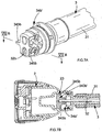
- Figures 7A and 7B show a modified version of the second mounting portion 34b'.
- Figure 7A shows the modified second mounting portion 34b' mounted on the end of a bendable hose portion 3 but exposed whereas
- Figure 7B shows the modified second mounting portion received in a recess 23 of a head 2 as is the case for the initial second mounting portion 34b as shown in Figure 5B .
- the modified second mounting portion 34b' still has two parts 343b' which form a wire engaging portion, are fixed around the end of the wire 32b and are received in the recess 23 to resist rotation of the wire engaging portion 343b' and hence end of the wire 32b.
- each of the two parts 343b' of the second mounting portion 34b' are screwed together to give secure fixing and avoid the use of sonic welding.
- each of the two parts 343b' of mounting portion 34b' comprises a wing or projection 345b which is arranged to support the parts 343b' against splaying.
- Each projection 345b abuts against a control surface in the receiving part so that splaying of the parts 343b' is resisted.
- the receiving part is of course the head 2 and the control surface is in the recess 23 of the head. However in other cases the control surface might be in another type of outlet portion or indeed in an inlet portion.
- the modified second mounting portion 34b' has two block portions extending transversely away from the wire for acceptance in an anti-rotation recess and two anti-splaying projections extending transversely away from the wire and angularly displaced from the block portions.
- the wire engaging portion 343b' of the modified second mounting portion 34b' has a generally cross-shaped axial cross-section.
- the wire 32 extends beyond the length of hose 31.
- the ends of the wire 32 are received in their respective wire engaging portions 343a/343b/343b' beyond (or outside of) the length of hose 31. This allows achievement of good anti-rotation characteristics without adversely increasing the diameter of the length of hose 31.
Landscapes
- Engineering & Computer Science (AREA)
- General Engineering & Computer Science (AREA)
- Mechanical Engineering (AREA)
- Water Supply & Treatment (AREA)
- Life Sciences & Earth Sciences (AREA)
- Environmental Sciences (AREA)
- Supports For Pipes And Cables (AREA)
- Rigid Pipes And Flexible Pipes (AREA)
Description
- This invention relates to garden water supplying apparatus which includes garden watering apparatus and garden aquatics apparatus. Garden watering apparatus includes amongst other things hoses, hose reels, hose guns, and watering lances. Garden aquatics apparatus includes pond pump and filtering systems and their connecting hoses.
- Such apparatus include tube like and/or hose like portions for supplying water. Tube like portions tend to lead to systems which are positionable but rigid. Hose like portions tend to lead to systems which are flexible but not positionable without separate retention means.
- It would be usefully to provide water supplying apparatus which are easily positionable for a certain use and may then be left unattended during their water supplying operation.
- Watering lances can be used as a specific example. Garden watering lances when connected to an appropriate feeder hose can be used for watering plants or washing items or surfaces.
- A garden watering lance typically has a handle or inlet portion, a head or outlet portion and a tube like portion therebetween so that there is a spacing between the head and the handle. This can be useful in providing additional reach for the user and may also help the user to be further way from the outlet of the water to avoid becoming wet or dirty.
- Whilst existing watering lances can be useful, there are a limited number of circumstances in which they can be used. Some existing watering lances will include a pivoting head that can pivot relative to the tube like portion to enable the head (that is the outlet) to be directed in different directions relative to the tube-like portion. This can assist, for example, in situations such as watering a hanging basket above the user's head.
- However it would be desirable for watering lances to be more versatile and therefore usable in a greater number of different situations. For example sometimes it is useful to be able to leave a hose and its outlet in a watering position unattended whilst performing other tasks. This is rarely practical with existing watering lances.
- Thus it would be desirable to provide more versatile garden water supplying apparatus which is made using cost effective and functionally effective materials.
-
US 6,568,610 describes a flexible lawn and garden spray wand which has a flexible tube assembly and a bendable metal rod which extends through the tube assembly. Thus the flexible tube assembly can be bent into a desired shape. - According to a first aspect of the present invention there is provided a bendable bend retaining garden water supplying hose portion as claimed in claim 1.
- This can allow the hose portion to be put in an operative position and left whilst carrying water. The bendable bend retaining hose portion might for example be wrapped around a post, branch, pole or similar.
- The expression plastically deformable is used here in the sense that the member holds its shape after deformation as opposed to resiliently returning to its original shape.
- With such a structure the length of hose can have the function of carrying water from the inlet end to the outlet end and the holding member can have the function of holding the length of hose and hence the whole bendable hose portion in a desired position.
- The mounting may be such as to allow relative axial movement between the length of hose and the holding member.
- The plastically deformable holding member may be mounted at each end to the length of hose. Each end of the plastically deformable holding member may be mounted in the length of hose against rotation relative to the length of hose. One end of the holding member may be mounted against axial movement relative to the length of hose. Another end of the holding member may be mounted so as to allow axial movement relative to the length of hose.
- At least one end of the holding member may comprise at least one respective retaining feature for reception in the mounting portion.
- The holding member may have at least one bend in the region of the mounting member to create two portions which are located in the holding member engaging portion of the mounting portion to resist relative rotation of the holding member relative to the mounting portion at the mounting portion.
- The holding member may have a hook shaped portion at one end. The hooked shaped portion may be, at least partially, located in the mounting portion.
- The holding member may have a simple bend at one end. The simple bend may be located in the mounting portion.
- The mounting portion may be arranged to be fed on one end of the holding member and slid along the holding member for engagement at the other end.
- The holding member engaging portion of the mounting portion may have at least two parts which are fixed together around the holding member. The two parts may be sonic welded together.
- The holding member engaging portion of the mounting portion may be axially moveable relative to the hose engaging portion of the mounting portion whilst held against rotation relative to the hose engaging portion. This can help accommodate the effect of different bend radiuses of the length of hose and holding member to help improve performance of the bendable bend retaining hose portion in use.
- The mounting portion may be arranged for insertion in an end of the length of hose.
- The hose engaging portion of the mounting portion may be barbed.
- There may be a pair of holding member mounting portions. One may be provided at a first end of the length of hose and another at a second end of the length of hose. Both mounting portions may be arranged to resist relative rotation of the holding member relative to the length of hose. One of the mounting portions may be arranged to resist axial movement of one end of the holding member relative to the length of hose and the other mounting portion may be arranged to allow axial movement of the other end of the holding member relative to the length of hose.
- A first of the mounting portions may be arranged to be fed on one end of the holding member and slid along the holding member for engagement at the other end and a second of the mounting portions may have at least two parts which are fixed together around the holding member.
- The bendable bend retaining hose portion may comprise a spacer member provided between the plastically deformable holding member and the length of hose.
- The spacer member may be tube shaped and surround the plastically deformable holding member and may comprise a second length of hose.
- The spacer member can help avoid undesirable kinking of the length of hose by limiting the minimum bend radius. Similarly this may help protect the plastically deformable holding member from fatigue.
- The plastically deformable holding member may comprise a wire. Typically the wire will be metallic, and may, for example, be of mild steel.
- The mounting portions may be of plastics material. The arrangement of the mounting portions and holding member can be such as to resist relative rotation therebetween without the need for any bond or weld between the mounting portions and the holding member. This can facilitate the use of differing materials for the holding member and the mounting portions.
- The inlet and outlet ends of the hose portion may be provided with adaptors for connection to other parts, in particular parts of a garden water supplying apparatus. The adaptors may be arranged for connection to an inlet portion and an outlet portion. The adaptors may comprise the mounting portions. The adaptors may comprise connection means (such as a threaded sleeve) and/or sealing means (such as an o-ring).
- According to a second aspect of the present invention there is provided a garden water supplying apparatus comprising an inlet portion, an outlet portion and in between the inlet portion and the outlet portion, a bendable bend retaining hose portion as defined above.
- At least one of the inlet portion and the outlet portion may have an abutting portion for abutting with a portion of the holding member to help keep the holding member engaged with the respective mounting portion.
- The inlet portion may comprise a handle portion. The inlet portion may have a connector for connecting to a feeder hose. The inlet portion may have a trigger for controlling flow of water through the apparatus, particularly through the bendable bend retaining hose portion.
- The outlet portion may comprise a feature head. The feature head may comprise a plurality of individually selectable feature outlets.
- The outlet portion may have a sprinkler outlet. In such a case, the bendable bend retaining hose portion may be bent into a configuration which allows the apparatus to be used as a lawn sprinkler.
- In other cases the inlet portion may, for example, be a hose pipe carrying an adaptor, and the outlet portion may, for example, be a hose gun, or another length of hose carrying an adaptor in such cases the hose gun, adaptor or so on may be arranged to connect with the respective end of the hose portion.
- In yet other cases the inlet portion and/or outlet portion may, for example comprise part of a garden aquatics system, and thus might comprise, for example, a pond pump, a pond filter, or a length of pond system hose carrying an adaptor. Again in such cases the pond filter, pond pump, adaptor and so on may be arranged to connect with the respective end of the hose portion.
- Not all of the optional features of the first aspect of the invention are repeated here for the sake of brevity, however, it will be appreciated that these features may also be optional of features of the other aspects of the invention mentioned above.
- According to a third aspect of the present invention there is provided a method of making a hose portion as claimed in
claim 16. - The step of fixing the two parts may comprise sonic welding.
- The method may comprise the step of introducing a spacer member into the length of hose, this may be done before the mounting portions are engaged at each end of the length of hose.
- The method may comprise the step of introducing at least one respective retaining feature at at least the second end of the holding member before feeding the holding member through the mounting members. At least one respective retaining feature may be introduced into each end of the holding member before feeding the holding member through the mounting members.
- At least one retaining feature may be introduced by bending the holding member.
- One retaining feature may be a simple bend, another may be a hook shaped portion.
- Embodiments of the present invention will now be described by way of example only, with reference to the accompanying drawings in which:
-
Figure 1 schematically shows a watering lance; -
Figure 2 shows the watering lance ofFigure 1 with a head portion and handle portion disconnected from an intermediate bendable bend retaining hose portion; -
Figure 3 is a sectional view of the bendable bend retaining hose portion of the watering lance shown inFigures 1 and Figures 2 ; -
Figure 4 shows an exploded view of the bendable bend retaining hose portion shown inFigure 3 ; -
Figures 5A and 5B are sectional views showing, in more detail, the connections between the bendable bend retaining hose portion on the one hand and the head portion and the handle portion on the other hand; -
Figures 6A and 6B show a modified form of mounting portion which may be used in an alternative version of the watering lance ofFigures 1 to 5A and 5B.Figure 6A shows the mounting portion fitted on the end of a length of hose andFigure 6B shows the mounting portion in isolation; and -
Figures 7A and 7B show a modified form of second mounting portion which may be used in an alternative version of the watering lance ofFigures 1 to 5A and5B , or similar products.Figure 7A shows the modified second mounting portion mounted on the end of a bendable hose portion andFigure 7B shows the modified second mounting portion in situ in a head to which the hose portion is connected. -
Figure 1 schematically shows a garden watering lance which generally comprises a handle or inlet portion 1, a head oroutlet portion 2 and connected between these two a bendable bend retaininghose portion 3. - The handle portion 1 comprises a connector 11 for connecting to a feeder hose, a
flow control mechanism 12 for providing an overall control of the rate of flow of water through the lance and atrigger portion 13 allowing the user to control the flow rate through the lance between off and the maximum set by theflow control mechanism 12. The handle portion 1 further comprises alock mechanism 14 for locking thetrigger 13 in an on position. - The
head 2 is a multi feature head in the present embodiment and thus has a plurality of independentlyselectable outlets 21. In the present embodiment one of these is a rose outlet and another is a sprinkler outlet and there may be further outlets providing different watering effects. Thesedifferent outlets 21 may be selected by the user rotating asleeve 22 of the head relative to the remainder of thehead 2. - The bendable bend retaining
hose portion 3 is connected between the handle 1 and thehead 2 and has the primary function of carrying water from the handle 1 to thehead 2. To this degree thehose portion 3 acts like the tube portion which will be included in a conventional watering lance. - However in the present watering lance, as mentioned above, the hose portion is a bendable bend retaining
hose portion 3 which means thehead 2 may be moved relative to the handle 1 by bending of thehose portion 3. Thus, for example, thehose portion 3 may be wrapped around a branch, post, or pole in order to hold the watering lance in position. Similarly the bendable bend retaininghose portion 3 of the lance may be simply bent to allow thehead 2 to be directed in a desired direction so that water leaving theoutlets 21 proceeds in a desired direction. - Further, the bendable bend retaining
hose portion 3 may be bent into a coil like configuration where the handle 1 and parts of the coil of thehose portion 3 rest on the ground and thehead 2 projects upwardly such that it may act as a lawn sprinkler. - The
lock mechanism 14 provided on the handle portion may then be used to lock thetrigger 13 in an on position such that the lance may be left unattended whilst in one of these chosen watering positions. - Note that, whilst in the present embodiment the bendable bend retaining
hose portion 3 is directly connected between the handle 1 andhead 2, in other situations a rigid tube portion might be introduced for example between the handle portion 1 and thehose portion 3. This would mean that the lance had a longer overall length (assuming thehose portion 3 has the same length) with a portion of the connection between the handle 1 andhead 2 being rigid and a portion being bendable. -
Figure 2 shows thehose portion 3 disconnected from the handle 1 andhead 2. In the present embodiment thehose portion 3 is a screw fit with both the handle portion 1 and thehead portion 2. -
Figures 3 and4 show the bendable bend retaininghose portion 3 in more detail.Figure 3 shows a section through the hose portion andFigure 4 shows an exploded view of thehose portion 3 so that the individual components can be more clearly seen.Figures 5A and 5B show the connections between thehose portion 3 and thehead 2 and handle 1 in more detail. - The
hose portion 3 comprises a length ofhose 31 with the primary function of carrying water from the handle 1 to thehead 2 and a plasticallydeformable wire portion 32 which runs within thehose 31 and acts as a holding member for holding the hose in a desired bent position and hence holding thehead 2 in a desired position relative to the handle 1. - Running between the length of
hose 31 andwire 32 is aspacer 33 which in the present embodiment is tubular and may for example be another length of hose. Thisspacer 33 occupies some of the volume within thehose 31 around thewire 32 and performs at least two functions in the present embodiment. First thespacer 33 tends to limit the minimum bend radius into which thehose portion 3 may be bent. This can have the benefits of reducing the chance of kinking of the hose, avoiding damage to the length ofhose 31 due to overbending and also can help to limit damage to thewire 32 due to overbending. It will be appreciated that repeated bending can cause fatigue and the provision of thespacer 33 helps to reduce the risk of any failure in the product due to fatigue. Thespacer 33 can also help to limit the volume of water in thehose portion 3 whilst allowing it to have a desirable overall outside diameter. Reducing the amount of water in thehose portion 3 reduces the weight of the lance which can help a user with operation of the device and can help to minimise the bending load on thewire 32 which it must resist. - Whilst the
spacer 33 is a piece of hose in the present embodiment, in other embodiments thespacer 33 may be differently constructed. Thus, for example, it might have axial through holes provided in its side walls along its length and might not be of hose type material. - The
wire 32 is mounted in the length ofhose 31 via a pair of mountingportions hose 31a and a second of which is provided at a second end of thehose 31b. - The first mounting
portion 34a has a barbedhose engaging portion 341a which is located in the first end of the length ofhose 31a. The hose is crimped to thehose engaging portion 341 a using aferrule 342a. The first mountingportion 34a further has awire engaging portion 343a with which afirst end 32a of the wire is engaged. - The
wire engaging portion 343a generally has the form of a hollow cylinder. This piece is moulded in one part with the correspondinghose engaging portion 341 a. - The first end of the
wire 32 is bent in the shape of a hook and this hook is engaged with the engagingportion 343a. This holds thefirst end 32a of thewire 32 against rotation relative to the first mountingportion 34a and hence against rotation relative to the first end of the length ofhose 31a. Thewire engaging portion 343a of the mountingportion 34a has appropriate recesses receiving two axially extendingparts parts wire 32 as a whole and similarly perpendicular to an axis of the length ofhose 31. In the present embodiment these twoportions wire 32 as a whole. This is not necessary in order to obtain the anti rotation function desired by helps improve this function/minimises the force which must be resisted in the recesses. - Also provided at this
first end 31 a of the length ofhose 31 is an o-ring 344a carried on the first mountingportion 34a and a threadedsleeve 35a. The threadedsleeve 35a is arranged to bear on the mountingportion 34a and to threadingly engage with a corresponding thread on the handle 1 to connect the first end of thebendable hose portion 3 to the handle 1. The o-ring 344a then seals on a corresponding surface in the handle 1. This connection between thebendable hose portion 3 and handle 1 can be seen most clearly inFigure 5A . - The handle portion 1 includes an
abutment portion 15 which abuts against the end of thewire 32 in particular against the end of the hook when thehose portion 3 is fitted to the handle 1. This means that when thebendable hose portion 3 is connected with the handle portion 1, axial movement of thewire 32 towards the handle 1 which might tend to disengage the hook portion from the mountingportion 34a is resisted. - Overall this means that a mechanically secure anti rotation connection can be achieved between the
wire 32 on the one hand and the mountingportion 34a and hence the length ofhose 31 on the other hand without having to use any form of bond or weld. This in turn facilitates the use of differing materials for the holding portion/wire 32 and the mountingportion 34a. - In the present embodiment the wire is metallic, for example, of mild steel whereas the mounting
portion 34a is of plastics material. - The structure provided at the other end of the
bendable hose portion 3 has some similarities with that described above but also some differences. - The
second mounting portion 34b is again secured in the length ofhose 31 this time at asecond end 31b. It comprises again a barbedhose engaging portion 341 b onto which the hose is secured by acorresponding ferrule 342b. Again awire engaging portion 343b is provided for securing thesecond end 32b of thewire 32. - However the structure of the second mounting
portion 34b is rather different. Thehose engaging portion 341b is separate from thewire engaging portion 343b. This is to facilitate manufacture of thebendable hose portion 3. In the case of the second mountingportion 34b the wire engaging portion has twoparts 343b which are sonic welded together around the second end of thewire 32b. The second end of thewire 32b has a simple bend and the two parts of thewire engaging portion 343b together form a cavity in which this simple bend is captured. Thus again there are two parts of the wire which are held in thewire engaging portion 343b with one being spaced from the other in a direction perpendicular to the axis of thewire 32/length ofhose 31. Thus again rotation of the end of thewire 32 relative to thehose engaging portion 343b may be resisted. - To achieve the aim of resisting rotation of this end of the
wire 32b relative to the length ofhose 31 the resultingblock 343b must be held against rotation relative to the length of hose. In the present embodiment this is achieved by virtue of the block being received in asuitable recess 23 provided in thehead 2. The connection between this second end of thebendable hose portion 3 and thehead 2 can be most clearly seen inFigure 5B . Therecess 23 again is most clearly seen inFigure 5B . - As most clearly seen in
Figure 5B the secondwire engaging portion 343b andrecess 23 are arranged such that thewire engaging portion 343b may move axially relative to therecess 23 and hence axially relative to thehead 2 and length ofhose 31. This allows for axial movement of the end of thewire 32 which will tend to occur as thebendable hose portion 3 is bent into different positions. This axial movement is due to the different bend radiuses which will be adopted by thewire 32 and the length ofhose 31 as thewhole hose portion 3 is bent. - Also provided at this second end of the
bendable hose portion 3 is an o-ring 344b carried on the mountingportion 34b and a threadedsleeve 35b which is arranged to bear on the mountingmember 34b and threadingly engaged with a corresponding thread on thehead 2. The o-ring 344b then seals with a corresponding surface in thehead 2. - In manufacturing of the
bendable hose portion 3 thespacer 33 is first provided in the length ofhose 31. Then the threadedsleeves hose 31. After this thehose engaging portions hose 31 and secured by theirrespective ferrules rings wire 32 has the appropriate bends put in its first 32a and second 32b ends to form the hook at thefirst end 32a and the simple bend at thesecond end 32b. Then thewire 32 is fed through the first mountingportion 34a and along the length ofhose 31 until thesecond end 32b of the wire reaches the second end. The hook at thefirst end 32a of thewire 32 is then engaged with the first mountingmember 34a. After this the parts of the secondwire engaging portion 343b are placed around the second end of thewire 32b and sonically welded into position. The bendable bend retaininghose portion 3 is then ready for connection to other components. - In the present embodiment, this is connection between the handle 1 and
head 2. - However, in other cases, then as alluded to above, other parts might be introduced between the bendable bend retaining
hose portion 3 and the handle 1 and/orhead 2. - In the arrangement of the lance mentioned above, there can be a tendency for the mounting
portion 34a provided at the first end of the length ofhose 31 to rotate within and relative to the handle portion 1. Anti-rotation features may be provided to resist this. Similarly anti-rotation features may be provided to resist relative rotation between the other mountingportion 34b at the second end of the length ofhose 31 and thehead 2. More generally anti-rotation features may be provided to resist rotation between at least one mountingportion inlet portion 2, 1. The anti-rotation features may comprise a series of projections on one part and a corresponding series of recesses on the other part. -
Figures 6A and 6B show a modified mountingportion 34a' includinganti-rotation splines 345a. In this case thesesplines 345a are provided on an outside surface of the hollow cylindricalwire engaging portion 343a. Otherwise the mountingportion 34a' is the same as the one 34a described above in relation toFigures 1 to 5 . Thesesplines 345a will engage with a corresponding set of splines provided on a facing bore surface of the handle portion (not shown) when the mountingportion 34a' is located in the handle portion 1 as the wholebendable hose portion 3 is connected to the handle 1. The corresponding bore surface 16 (where the splines would be provided) of the handle 1 of the embodiment ofFigures 1 to 5 can be seen inFigure 5A . - Whilst the above description has been in the terms of a watering lance it should be appreciated that the bendable bend retaining hose portion described above may be used in other garden water supplying products in particular other garden watering or garden pond equipment. Thus in general terms there will be an inlet portion such as the handle portion 1 but not limited to handle portions and an outlet portion such as the
head 2 with the bendable bend retaininghose portion 3 provided therebetween. Of course as mentioned above, other components might be provided between these components. - Thus the bendable bend retaining
hose portion 3 might be supplied as a component on its own or integrated into a larger product including the inlet portion and outlet portion. It is conceivable, for example, that the inlet portion might comprise a hose and the outlet portion might comprise a hose in each case with a suitable adaptor at the end for connecting to the bendable bend retaining hose portion. In the case of a bendable bend retaininghose portion 3 of the type described above, the adaptor (or other component) to which the first end of thehose portion 3 is connected should preferably have an abutment member for abutting against the end of the holding member/wire 32 as in the case of the lance handle 1 described above. Similarly the adaptor (or other component) for connecting to the second end of thehose portion 3 should preferably have a recess for controlling movement of the secondwire engaging portion 343b as provided in thehead 2 in the lance above. That is to say a recess which on the one hand restricts rotational movement of thewire engaging portion 343b relative to the adaptor and hence the length of hose 1 whilst allowing axial movement of thewire engaging portion 343b. - As a specific alternative example the outlet portion might be a hose gun in the place of the
head 2 in the embodiment shown above and the inlet portion might be a hose provided with a suitable adaptor. - It has been found during testing of devices including second mounting
portions 34b of the type shown above, for example inFigures 3 and5B , that the sonic weldedparts 343b can be forced apart with repeated use. The relatively high forces acting on theparts 343b due to the torque applied to thewire 32 in bending of thebendable hose portion 3 can cause the parts to splay apart. - It has also been found that the welding process can damage any anticorrosion coating on the deformable wire.
-
Figures 7A and 7B show a modified version of the second mountingportion 34b'.Figure 7A shows the modified second mountingportion 34b' mounted on the end of abendable hose portion 3 but exposed whereasFigure 7B shows the modified second mounting portion received in arecess 23 of ahead 2 as is the case for the initial second mountingportion 34b as shown inFigure 5B . Note however that the section shown inFigure 7B is taken at 90° to that shown inFigure 5B . - The modified second mounting
portion 34b' still has twoparts 343b' which form a wire engaging portion, are fixed around the end of thewire 32b and are received in therecess 23 to resist rotation of thewire engaging portion 343b' and hence end of thewire 32b. - However, the two
parts 343b' of the second mountingportion 34b' are screwed together to give secure fixing and avoid the use of sonic welding. Further each of the twoparts 343b' of mountingportion 34b' comprises a wing orprojection 345b which is arranged to support theparts 343b' against splaying. Eachprojection 345b abuts against a control surface in the receiving part so that splaying of theparts 343b' is resisted. In the present embodiment the receiving part is of course thehead 2 and the control surface is in therecess 23 of the head. However in other cases the control surface might be in another type of outlet portion or indeed in an inlet portion. - As a whole the modified second mounting
portion 34b' has two block portions extending transversely away from the wire for acceptance in an anti-rotation recess and two anti-splaying projections extending transversely away from the wire and angularly displaced from the block portions. Thewire engaging portion 343b' of the modified second mountingportion 34b' has a generally cross-shaped axial cross-section. - It will be noted that in each of the arrangement described and shown above the
wire 32 extends beyond the length ofhose 31. The ends of thewire 32 are received in their respectivewire engaging portions 343a/343b/343b' beyond (or outside of) the length ofhose 31. This allows achievement of good anti-rotation characteristics without adversely increasing the diameter of the length ofhose 31.
Claims (16)
- A bendable bend retaining garden water supplying hose portion having an inlet end and an outlet end and comprising a length of hose (31) and a plastically deformable holding member (32) running within the length of the hose (31), the hose portion being bendable to allow the outlet end to be moved relative to the inlet end and being arranged for holding its position when bent as desired, wherein
the holding member (32) is mounted to the length of hose (31), and
the hose portion comprises at least one holding member mounting portion (34a, 34b), which has a hose engaging portion (341 a) which engages with the length of hose and a holding member engaging portion (343a) which engages with the holding member (32) at a position beyond the length of hose, and the holding member has two portions (321a, 322a) which are located in the holding member engaging portion (343a) of the mounting portion and which are spaced from one another in a direction transverse to the axis of the hose in the region of the mounting member portion, for resisting rotation of the holding member relative to the mounting portion at the mounting portion. - A hose portion according to claim 1 in which the holding member (32) has at least one bend in the region of the mounting portion to create the two portions (321 a, 322a) which are located in the holding member engaging portion (343a) of the mounting portion (34a) to resist relative rotation of the holding member (32) relative to the mounting portion at the mounting portion.
- A hose portion according to claim 1 or claim 2 in which the holding member (32) has a hook shaped portion at one end.
- A hose portion according to any one of claims 1 to 3 in which the bendable bend retaining hose portion comprises a spacer member (33) provided between the plastically deformable holding member (32) and the length of hose (31).
- A hose portion according to any preceding claim in which the mounting portion (34a, 34b) is such as to allow relative axial movement between the length of hose (31) and the holding member (32).
- A hose portion according to any preceding claim in which the holding member (32) is mounted at each end to the length of hose (31).
- A hose portion according to any preceding claim in which each end of the plastically deformable holding member (32) is mounted in the length of hose against rotation relative to the length of hose (31).
- A hose portion according to any preceding claim in which there is a pair of holding member mounting portions (343a, 343b), a first of the mounting portions (343a) being arranged to be fed on one end of the holding member (32) and slid along the holding member (32) for engagement at the other end and a second of the mounting portions (343b) having at least two parts which are fixed together around the holding member (32).
- A hose portion according to claim 8 in which the holding member engaging portion (343b) of one of the mounting portions (34b) is axially moveable relative to the hose engaging portion (341 b) of the mounting portion (34b) whilst held against rotation relative to the hose engaging portion (341 b).
- A hose portion according to any preceding claim in which the, or one of the, holding member engaging portions comprises anti-splaying projections (345b) for acting on a control surface of a corresponding inlet or outlet portion into which the engaging portion is introduced.
- Garden water supplying apparatus comprising an inlet portion (1) and an outlet portion (2) and connected therebetween a bendable bend retaining hose portion according to any preceding claim.
- Garden water supplying apparatus according to claim 11 in which the hose portion has a pair of holding member engaging portions (343a, 343b) and the inlet portion (1), outlet portion (2) and pair of holding member engaging portions (343a, 343b) having corresponding anti-rotation features to resist rotation between the respective engaging portion and the respective one of the inlet and outlet portions.
- Garden water supplying apparatus according to claim 11 or 12 wherein at least one of the inlet portion (1) and outlet portion (2) has an abutting portion (15) for abutting with a portion of the holding member to help keep the holding member engaged with a respective mounting portion.
- Garden water supplying apparatus according to any one of claims 11 to 13 in which the outlet portion has a sprinkler outlet and the bendable bend retaining hose portion is bendable into a configuration which allows the apparatus to be used as a lawn sprinkler.
- Garden water supplying apparatus according to any one of claims 11 to 14 wherein the garden water supply apparatus comprises a watering lance.
- A method of making a bendable bend retaining hose portion according to claim 1, wherein the bendable bend retaining hose portion comprises a pair of holding member mounting portions (34a, 34b) each of which has a hose engaging portion (341 a, 341 b) which engages with the length of hose (31) and a holding member engaging portion (343a, 343b) with which the holding member (32) engages so that a first end of the holding member is engaged with a first of the mounting members and a second end of the holding member is engaged with a second of the mounting members, the method comprising the steps of:engaging the hose engaging portion (341 a) of the first of the mounting portions with a first end of the length of hose;engaging the hose engaging portion (341 b) of the second of the mounting portions with a second end of the length of hose;feeding the second end of the holding member (32) through an aperture in the first of the mounting portions (34a) and into the length of hose;continuing to feed the holding member (32) through the first of the mounting portions (34a) until locating the first end of the holding member in the first of the mounting portions as that end reaches the mounting portion;feeding the second end of the holding member through an aperture in the hose engaging portion of a second of the mounting portions (34b);wherein the holding member engaging portion (343b) of the second of the mounting portions (34b) has at least two parts and the method comprises fixing the two parts together around the second end of the holding member (32), after passing the second end of the holding member through the aperture in the hose engaging portion of the second of the mounting portions, to capture the second end of the holding member.
Priority Applications (1)
| Application Number | Priority Date | Filing Date | Title |
|---|---|---|---|
| PL12809296T PL2806729T3 (en) | 2012-01-26 | 2012-11-19 | Garden water supplying apparatus |
Applications Claiming Priority (2)
| Application Number | Priority Date | Filing Date | Title |
|---|---|---|---|
| GB1201449.4A GB2498779A (en) | 2012-01-26 | 2012-01-26 | Bendable garden water supplying apparatus |
| PCT/GB2012/000846 WO2013110908A1 (en) | 2012-01-26 | 2012-11-19 | Garden water supplying apparatus |
Publications (2)
| Publication Number | Publication Date |
|---|---|
| EP2806729A1 EP2806729A1 (en) | 2014-12-03 |
| EP2806729B1 true EP2806729B1 (en) | 2016-09-28 |
Family
ID=45876225
Family Applications (1)
| Application Number | Title | Priority Date | Filing Date |
|---|---|---|---|
| EP12809296.2A Active EP2806729B1 (en) | 2012-01-26 | 2012-11-19 | Garden water supplying apparatus |
Country Status (7)
| Country | Link |
|---|---|
| EP (1) | EP2806729B1 (en) |
| CN (1) | CN104080329B (en) |
| AU (1) | AU2012367836B2 (en) |
| ES (1) | ES2605455T3 (en) |
| GB (1) | GB2498779A (en) |
| PL (1) | PL2806729T3 (en) |
| WO (1) | WO2013110908A1 (en) |
Family Cites Families (9)
| Publication number | Priority date | Publication date | Assignee | Title |
|---|---|---|---|---|
| JPS5531083U (en) * | 1978-08-23 | 1980-02-28 | ||
| JPH0515267A (en) * | 1991-07-11 | 1993-01-26 | Shoji Hanaoka | Sprinkler for plant raising |
| CN1104736A (en) * | 1993-11-18 | 1995-07-05 | 李明仁 | Manufacturing method of flexible soft permeable pipe |
| AU5172196A (en) * | 1995-02-27 | 1996-09-18 | Randy J. Cooper | Lawn and garden sprinkler with bendable tubes |
| US5894866A (en) * | 1997-07-31 | 1999-04-20 | Dayco Products, Inc. | Garden hose assembly having holding means adapted to be coiled around an associated support and method of making same |
| JP3426507B2 (en) * | 1998-06-25 | 2003-07-14 | 直樹 渡邉 | Mobile liquid supply device |
| US6568610B1 (en) * | 2000-08-12 | 2003-05-27 | K. C. Ericksen | Flexible lawn and garden spray wand |
| US7614569B2 (en) * | 2005-08-16 | 2009-11-10 | Lavacot Kenneth R | Stream nozzle |
| US7891382B2 (en) * | 2005-12-16 | 2011-02-22 | Mercury Plastics, Inc. | Overmolded and bendable position-retaining tubing |
-
2012
- 2012-01-26 GB GB1201449.4A patent/GB2498779A/en not_active Withdrawn
- 2012-11-19 PL PL12809296T patent/PL2806729T3/en unknown
- 2012-11-19 AU AU2012367836A patent/AU2012367836B2/en not_active Ceased
- 2012-11-19 CN CN201280068210.3A patent/CN104080329B/en active Active
- 2012-11-19 WO PCT/GB2012/000846 patent/WO2013110908A1/en not_active Ceased
- 2012-11-19 ES ES12809296.2T patent/ES2605455T3/en active Active
- 2012-11-19 EP EP12809296.2A patent/EP2806729B1/en active Active
Also Published As
| Publication number | Publication date |
|---|---|
| GB201201449D0 (en) | 2012-03-14 |
| PL2806729T3 (en) | 2017-04-28 |
| EP2806729A1 (en) | 2014-12-03 |
| AU2012367836B2 (en) | 2017-03-09 |
| GB2498779A (en) | 2013-07-31 |
| AU2012367836A1 (en) | 2014-06-19 |
| CN104080329B (en) | 2016-01-13 |
| CN104080329A (en) | 2014-10-01 |
| ES2605455T3 (en) | 2017-03-14 |
| WO2013110908A1 (en) | 2013-08-01 |
Similar Documents
| Publication | Publication Date | Title |
|---|---|---|
| US8448370B2 (en) | Quick release connector for firearm cleaning kit and method for using the same | |
| US9736992B1 (en) | Floral support device for a tombstone | |
| US20150219259A1 (en) | Swivel hose coupling with outer grip | |
| US6568610B1 (en) | Flexible lawn and garden spray wand | |
| US10267102B2 (en) | Ball socket connector | |
| EP3127620A1 (en) | Device and method for applying a liquid coating material to a portion of a fastening element | |
| EP2982808B1 (en) | Coupling for connecting construction parts, a truss provided therewith and associated method and use | |
| US8523121B2 (en) | Sprinkler elevating apparatus and method | |
| US10072762B2 (en) | Adapter valve assembly | |
| US9038922B1 (en) | Spray containment device and methods of use | |
| AU2021417771A1 (en) | Water path integrated device and refrigerator with same | |
| AU2012367836B2 (en) | Garden water supplying apparatus | |
| RU2678152C2 (en) | Device for supplying sprayer with liquid coating product | |
| US10526161B2 (en) | Wire spool guide | |
| CA2310001A1 (en) | Joint | |
| US20150202748A1 (en) | System for sprinkler housing removal | |
| JP5607976B2 (en) | Connecting joint for rod-shaped members | |
| JP5342723B2 (en) | Wiring and piping material support assembly | |
| CN111053998A (en) | Multi-degree-of-freedom cannon | |
| US20080209687A1 (en) | Bendable extension arm | |
| US6926213B2 (en) | Power washer wand | |
| JP4673249B2 (en) | Cable connector pulling cap device and optical cable wiring method using the same | |
| CN104876071A (en) | Special pipe winder for irrigation water pipes | |
| CN210328818U (en) | Irrigation is with driping irrigation device | |
| JP2021534724A (en) | Epoxyless remote control vehicle termination |
Legal Events
| Date | Code | Title | Description |
|---|---|---|---|
| PUAI | Public reference made under article 153(3) epc to a published international application that has entered the european phase |
Free format text: ORIGINAL CODE: 0009012 |
|
| 17P | Request for examination filed |
Effective date: 20140528 |
|
| AK | Designated contracting states |
Kind code of ref document: A1 Designated state(s): AL AT BE BG CH CY CZ DE DK EE ES FI FR GB GR HR HU IE IS IT LI LT LU LV MC MK MT NL NO PL PT RO RS SE SI SK SM TR |
|
| DAX | Request for extension of the european patent (deleted) | ||
| RAP1 | Party data changed (applicant data changed or rights of an application transferred) |
Owner name: EXEL INDUSTRIES S.A. |
|
| GRAP | Despatch of communication of intention to grant a patent |
Free format text: ORIGINAL CODE: EPIDOSNIGR1 |
|
| INTG | Intention to grant announced |
Effective date: 20160407 |
|
| GRAS | Grant fee paid |
Free format text: ORIGINAL CODE: EPIDOSNIGR3 |
|
| GRAA | (expected) grant |
Free format text: ORIGINAL CODE: 0009210 |
|
| RAP1 | Party data changed (applicant data changed or rights of an application transferred) |
Owner name: SA EXEL INDUSTRIES |
|
| AK | Designated contracting states |
Kind code of ref document: B1 Designated state(s): AL AT BE BG CH CY CZ DE DK EE ES FI FR GB GR HR HU IE IS IT LI LT LU LV MC MK MT NL NO PL PT RO RS SE SI SK SM TR |
|
| REG | Reference to a national code |
Ref country code: GB Ref legal event code: FG4D |
|
| REG | Reference to a national code |
Ref country code: CH Ref legal event code: EP |
|
| REG | Reference to a national code |
Ref country code: AT Ref legal event code: REF Ref document number: 831976 Country of ref document: AT Kind code of ref document: T Effective date: 20161015 |
|
| REG | Reference to a national code |
Ref country code: IE Ref legal event code: FG4D |
|
| REG | Reference to a national code |
Ref country code: NL Ref legal event code: FP |
|
| REG | Reference to a national code |
Ref country code: DE Ref legal event code: R096 Ref document number: 602012023585 Country of ref document: DE |
|
| REG | Reference to a national code |
Ref country code: FR Ref legal event code: PLFP Year of fee payment: 5 |
|
| REG | Reference to a national code |
Ref country code: LT Ref legal event code: MG4D |
|
| PG25 | Lapsed in a contracting state [announced via postgrant information from national office to epo] |
Ref country code: RS Free format text: LAPSE BECAUSE OF FAILURE TO SUBMIT A TRANSLATION OF THE DESCRIPTION OR TO PAY THE FEE WITHIN THE PRESCRIBED TIME-LIMIT Effective date: 20160928 Ref country code: LT Free format text: LAPSE BECAUSE OF FAILURE TO SUBMIT A TRANSLATION OF THE DESCRIPTION OR TO PAY THE FEE WITHIN THE PRESCRIBED TIME-LIMIT Effective date: 20160928 Ref country code: NO Free format text: LAPSE BECAUSE OF FAILURE TO SUBMIT A TRANSLATION OF THE DESCRIPTION OR TO PAY THE FEE WITHIN THE PRESCRIBED TIME-LIMIT Effective date: 20161228 Ref country code: FI Free format text: LAPSE BECAUSE OF FAILURE TO SUBMIT A TRANSLATION OF THE DESCRIPTION OR TO PAY THE FEE WITHIN THE PRESCRIBED TIME-LIMIT Effective date: 20160928 Ref country code: HR Free format text: LAPSE BECAUSE OF FAILURE TO SUBMIT A TRANSLATION OF THE DESCRIPTION OR TO PAY THE FEE WITHIN THE PRESCRIBED TIME-LIMIT Effective date: 20160928 |
|
| REG | Reference to a national code |
Ref country code: AT Ref legal event code: MK05 Ref document number: 831976 Country of ref document: AT Kind code of ref document: T Effective date: 20160928 |
|
| PG25 | Lapsed in a contracting state [announced via postgrant information from national office to epo] |
Ref country code: SE Free format text: LAPSE BECAUSE OF FAILURE TO SUBMIT A TRANSLATION OF THE DESCRIPTION OR TO PAY THE FEE WITHIN THE PRESCRIBED TIME-LIMIT Effective date: 20160928 Ref country code: GR Free format text: LAPSE BECAUSE OF FAILURE TO SUBMIT A TRANSLATION OF THE DESCRIPTION OR TO PAY THE FEE WITHIN THE PRESCRIBED TIME-LIMIT Effective date: 20161229 Ref country code: LV Free format text: LAPSE BECAUSE OF FAILURE TO SUBMIT A TRANSLATION OF THE DESCRIPTION OR TO PAY THE FEE WITHIN THE PRESCRIBED TIME-LIMIT Effective date: 20160928 |
|
| REG | Reference to a national code |
Ref country code: ES Ref legal event code: FG2A Ref document number: 2605455 Country of ref document: ES Kind code of ref document: T3 Effective date: 20170314 |
|
| PG25 | Lapsed in a contracting state [announced via postgrant information from national office to epo] |
Ref country code: RO Free format text: LAPSE BECAUSE OF FAILURE TO SUBMIT A TRANSLATION OF THE DESCRIPTION OR TO PAY THE FEE WITHIN THE PRESCRIBED TIME-LIMIT Effective date: 20160928 Ref country code: EE Free format text: LAPSE BECAUSE OF FAILURE TO SUBMIT A TRANSLATION OF THE DESCRIPTION OR TO PAY THE FEE WITHIN THE PRESCRIBED TIME-LIMIT Effective date: 20160928 |
|
| PG25 | Lapsed in a contracting state [announced via postgrant information from national office to epo] |
Ref country code: IS Free format text: LAPSE BECAUSE OF FAILURE TO SUBMIT A TRANSLATION OF THE DESCRIPTION OR TO PAY THE FEE WITHIN THE PRESCRIBED TIME-LIMIT Effective date: 20170128 Ref country code: PT Free format text: LAPSE BECAUSE OF FAILURE TO SUBMIT A TRANSLATION OF THE DESCRIPTION OR TO PAY THE FEE WITHIN THE PRESCRIBED TIME-LIMIT Effective date: 20170130 Ref country code: BG Free format text: LAPSE BECAUSE OF FAILURE TO SUBMIT A TRANSLATION OF THE DESCRIPTION OR TO PAY THE FEE WITHIN THE PRESCRIBED TIME-LIMIT Effective date: 20161228 Ref country code: SM Free format text: LAPSE BECAUSE OF FAILURE TO SUBMIT A TRANSLATION OF THE DESCRIPTION OR TO PAY THE FEE WITHIN THE PRESCRIBED TIME-LIMIT Effective date: 20160928 Ref country code: AT Free format text: LAPSE BECAUSE OF FAILURE TO SUBMIT A TRANSLATION OF THE DESCRIPTION OR TO PAY THE FEE WITHIN THE PRESCRIBED TIME-LIMIT Effective date: 20160928 Ref country code: SK Free format text: LAPSE BECAUSE OF FAILURE TO SUBMIT A TRANSLATION OF THE DESCRIPTION OR TO PAY THE FEE WITHIN THE PRESCRIBED TIME-LIMIT Effective date: 20160928 Ref country code: CZ Free format text: LAPSE BECAUSE OF FAILURE TO SUBMIT A TRANSLATION OF THE DESCRIPTION OR TO PAY THE FEE WITHIN THE PRESCRIBED TIME-LIMIT Effective date: 20160928 |
|
| REG | Reference to a national code |
Ref country code: DE Ref legal event code: R097 Ref document number: 602012023585 Country of ref document: DE |
|
| REG | Reference to a national code |
Ref country code: CH Ref legal event code: PL |
|
| PG25 | Lapsed in a contracting state [announced via postgrant information from national office to epo] |
Ref country code: CH Free format text: LAPSE BECAUSE OF NON-PAYMENT OF DUE FEES Effective date: 20161130 Ref country code: DK Free format text: LAPSE BECAUSE OF FAILURE TO SUBMIT A TRANSLATION OF THE DESCRIPTION OR TO PAY THE FEE WITHIN THE PRESCRIBED TIME-LIMIT Effective date: 20160928 Ref country code: LI Free format text: LAPSE BECAUSE OF NON-PAYMENT OF DUE FEES Effective date: 20161130 |
|
| PLBE | No opposition filed within time limit |
Free format text: ORIGINAL CODE: 0009261 |
|
| STAA | Information on the status of an ep patent application or granted ep patent |
Free format text: STATUS: NO OPPOSITION FILED WITHIN TIME LIMIT |
|
| REG | Reference to a national code |
Ref country code: IE Ref legal event code: MM4A |
|
| 26N | No opposition filed |
Effective date: 20170629 |
|
| PG25 | Lapsed in a contracting state [announced via postgrant information from national office to epo] |
Ref country code: LU Free format text: LAPSE BECAUSE OF NON-PAYMENT OF DUE FEES Effective date: 20161130 |
|
| REG | Reference to a national code |
Ref country code: FR Ref legal event code: PLFP Year of fee payment: 6 |
|
| PG25 | Lapsed in a contracting state [announced via postgrant information from national office to epo] |
Ref country code: SI Free format text: LAPSE BECAUSE OF FAILURE TO SUBMIT A TRANSLATION OF THE DESCRIPTION OR TO PAY THE FEE WITHIN THE PRESCRIBED TIME-LIMIT Effective date: 20160928 Ref country code: IE Free format text: LAPSE BECAUSE OF NON-PAYMENT OF DUE FEES Effective date: 20161119 |
|
| PG25 | Lapsed in a contracting state [announced via postgrant information from national office to epo] |
Ref country code: HU Free format text: LAPSE BECAUSE OF FAILURE TO SUBMIT A TRANSLATION OF THE DESCRIPTION OR TO PAY THE FEE WITHIN THE PRESCRIBED TIME-LIMIT; INVALID AB INITIO Effective date: 20121119 |
|
| PG25 | Lapsed in a contracting state [announced via postgrant information from national office to epo] |
Ref country code: MC Free format text: LAPSE BECAUSE OF FAILURE TO SUBMIT A TRANSLATION OF THE DESCRIPTION OR TO PAY THE FEE WITHIN THE PRESCRIBED TIME-LIMIT Effective date: 20160928 Ref country code: MK Free format text: LAPSE BECAUSE OF FAILURE TO SUBMIT A TRANSLATION OF THE DESCRIPTION OR TO PAY THE FEE WITHIN THE PRESCRIBED TIME-LIMIT Effective date: 20160928 Ref country code: CY Free format text: LAPSE BECAUSE OF FAILURE TO SUBMIT A TRANSLATION OF THE DESCRIPTION OR TO PAY THE FEE WITHIN THE PRESCRIBED TIME-LIMIT Effective date: 20160928 |
|
| PG25 | Lapsed in a contracting state [announced via postgrant information from national office to epo] |
Ref country code: MT Free format text: LAPSE BECAUSE OF NON-PAYMENT OF DUE FEES Effective date: 20161119 |
|
| PG25 | Lapsed in a contracting state [announced via postgrant information from national office to epo] |
Ref country code: AL Free format text: LAPSE BECAUSE OF FAILURE TO SUBMIT A TRANSLATION OF THE DESCRIPTION OR TO PAY THE FEE WITHIN THE PRESCRIBED TIME-LIMIT Effective date: 20160928 Ref country code: TR Free format text: LAPSE BECAUSE OF FAILURE TO SUBMIT A TRANSLATION OF THE DESCRIPTION OR TO PAY THE FEE WITHIN THE PRESCRIBED TIME-LIMIT Effective date: 20160928 |
|
| PGFP | Annual fee paid to national office [announced via postgrant information from national office to epo] |
Ref country code: NL Payment date: 20251028 Year of fee payment: 14 |
|
| PGFP | Annual fee paid to national office [announced via postgrant information from national office to epo] |
Ref country code: DE Payment date: 20251117 Year of fee payment: 14 |
|
| PGFP | Annual fee paid to national office [announced via postgrant information from national office to epo] |
Ref country code: GB Payment date: 20251126 Year of fee payment: 14 |
|
| PGFP | Annual fee paid to national office [announced via postgrant information from national office to epo] |
Ref country code: IT Payment date: 20251111 Year of fee payment: 14 |
|
| PGFP | Annual fee paid to national office [announced via postgrant information from national office to epo] |
Ref country code: FR Payment date: 20251127 Year of fee payment: 14 |
|
| PGFP | Annual fee paid to national office [announced via postgrant information from national office to epo] |
Ref country code: BE Payment date: 20251120 Year of fee payment: 14 |
|
| PGFP | Annual fee paid to national office [announced via postgrant information from national office to epo] |
Ref country code: PL Payment date: 20251020 Year of fee payment: 14 |
|
| PGFP | Annual fee paid to national office [announced via postgrant information from national office to epo] |
Ref country code: ES Payment date: 20251210 Year of fee payment: 14 |