EP2806715A1 - Beam splitter for FEL undulator - Google Patents
Beam splitter for FEL undulator Download PDFInfo
- Publication number
- EP2806715A1 EP2806715A1 EP13191927.6A EP13191927A EP2806715A1 EP 2806715 A1 EP2806715 A1 EP 2806715A1 EP 13191927 A EP13191927 A EP 13191927A EP 2806715 A1 EP2806715 A1 EP 2806715A1
- Authority
- EP
- European Patent Office
- Prior art keywords
- charged particle
- particle beam
- undulator
- kicker
- projected direction
- Prior art date
- Legal status (The legal status is an assumption and is not a legal conclusion. Google has not performed a legal analysis and makes no representation as to the accuracy of the status listed.)
- Withdrawn
Links
- 239000002245 particle Substances 0.000 claims abstract description 48
- 230000005469 synchrotron radiation Effects 0.000 claims abstract description 12
- 230000005684 electric field Effects 0.000 claims description 5
- 239000003574 free electron Substances 0.000 claims description 5
- 238000000206 photolithography Methods 0.000 claims description 4
- 230000001360 synchronised effect Effects 0.000 claims description 4
- 238000011144 upstream manufacturing Methods 0.000 claims description 4
- 230000007935 neutral effect Effects 0.000 claims description 3
- 230000005855 radiation Effects 0.000 abstract description 13
- 238000012546 transfer Methods 0.000 abstract description 3
- 238000010894 electron beam technology Methods 0.000 description 17
- 230000000737 periodic effect Effects 0.000 description 5
- 230000010355 oscillation Effects 0.000 description 4
- 238000009826 distribution Methods 0.000 description 3
- 238000006073 displacement reaction Methods 0.000 description 2
- 238000003780 insertion Methods 0.000 description 2
- 230000037431 insertion Effects 0.000 description 2
- 238000000034 method Methods 0.000 description 2
- 238000001228 spectrum Methods 0.000 description 2
- 230000004913 activation Effects 0.000 description 1
- 239000003990 capacitor Substances 0.000 description 1
- 239000000919 ceramic Substances 0.000 description 1
- 238000006243 chemical reaction Methods 0.000 description 1
- 239000011248 coating agent Substances 0.000 description 1
- 238000000576 coating method Methods 0.000 description 1
- 230000001427 coherent effect Effects 0.000 description 1
- 238000013461 design Methods 0.000 description 1
- 230000000694 effects Effects 0.000 description 1
- 238000002474 experimental method Methods 0.000 description 1
- 238000009434 installation Methods 0.000 description 1
- 238000005457 optimization Methods 0.000 description 1
- 238000011084 recovery Methods 0.000 description 1
- 239000004065 semiconductor Substances 0.000 description 1
- 238000000926 separation method Methods 0.000 description 1
- 238000007493 shaping process Methods 0.000 description 1
- 230000003595 spectral effect Effects 0.000 description 1
- 230000003068 static effect Effects 0.000 description 1
- 238000003860 storage Methods 0.000 description 1
Images
Classifications
-
- H—ELECTRICITY
- H05—ELECTRIC TECHNIQUES NOT OTHERWISE PROVIDED FOR
- H05H—PLASMA TECHNIQUE; PRODUCTION OF ACCELERATED ELECTRICALLY-CHARGED PARTICLES OR OF NEUTRONS; PRODUCTION OR ACCELERATION OF NEUTRAL MOLECULAR OR ATOMIC BEAMS
- H05H7/00—Details of devices of the types covered by groups H05H9/00, H05H11/00, H05H13/00
- H05H7/04—Magnet systems, e.g. undulators, wigglers; Energisation thereof
-
- H—ELECTRICITY
- H05—ELECTRIC TECHNIQUES NOT OTHERWISE PROVIDED FOR
- H05H—PLASMA TECHNIQUE; PRODUCTION OF ACCELERATED ELECTRICALLY-CHARGED PARTICLES OR OF NEUTRONS; PRODUCTION OR ACCELERATION OF NEUTRAL MOLECULAR OR ATOMIC BEAMS
- H05H7/00—Details of devices of the types covered by groups H05H9/00, H05H11/00, H05H13/00
- H05H7/04—Magnet systems, e.g. undulators, wigglers; Energisation thereof
- H05H2007/041—Magnet systems, e.g. undulators, wigglers; Energisation thereof for beam bunching, e.g. undulators
Definitions
- the present invention relates to a charged particle beam undulator system for generating synchrotron radiation.
- Charged particle beams in particular in free-electron lasers (FELs), are a flexible tool for generating ultra-bright, coherent radiation with wavelengths ranging from the microwave to the hard x-ray regime.
- FELs free-electron lasers
- high-gain FELs are utilized, in which a bunch train of ultra-relativistic electrons passes through a long undulator for a single time.
- the undulator a periodic arrangement of magnets, synchrotron light is emitted, which interacts with the electron beam in a way that the emitted light power grows exponentially within the undulator until a saturation state is reached. In this state, approximately 10 -2 to 10 -4 of the kinetic energy of the electron beam is transferred to the photon beam, which is emitted with a narrow spectral bandwidth, a small beam size, and divergence angle.
- FELs an interesting tool for providing high power beams at short wavelengths.
- a high-power electron accelerator for example an energy-recovery linear accelerator with the potential of generating a suitable electron beam with tens to hundreds of MW of beam power
- photon beams with tens of kW of power in the EUV wavelength range are feasible.
- Such a machine would, for example, be a possible radiation source for next-generation photolithography applications at wavelengths of 13.5 nm, 6 nm, and shorter.
- a charged particle beam undulator system for generating radiation, preferably synchrotron radiation comprising:
- the present kicker system enables the transfer of the radiation to various user stations by using only one single undulator.
- the delivery of the radiation to various user stations achieved by deflecting the charged particle beam from its straight particle trajectory is widely controllable by an appropriate steering of the kicker system. This results in a broad range of possibilities of a positional and/or an angular offset of the charged particle beam leading to a change in the projected direction or in projected position or a combination of change of direction and position.
- the charged particle beam is part of a free-electron laser (FEL).
- FEL free-electron laser
- a free-electron laser for wavelengths in the vacuum ultra-violet and shorter can be realized as a high-gain FEL.
- the FEL delivers a sufficient yield of synchrotron radiation which enables a transfer of approximately 10 -2 to 10 -4 of the kinetic energy of the electron beam to the photon beam in its saturation state towards the end of the undulator.
- a further preferred embodiment of the present invention provides for a number of further kicker systems, wherein said number of further kicker systems being disposed between adjacent dipole magnets.
- the charged particle beam can be newly adjusted.
- Possible set-up could also provide for a separate kicker system for each pair of dipole magnets.
- a further kicker system is disposed downstream of the number of dipole magnets.
- An appropriate controlling of the kicker system can be achieved when said charged particle beam is discontinuously emitted in a number of bunches, wherein said magnet deflecting unit and/or the electric field deflecting unit is/are controlled to deflect the charged particle beam synchronized to said bunches.
- This synchronization is effected in terms of a fast switch from one projected direction of the charged particle beam to another projected direction of the charged particle beam during the interval between two bunches of the charged particle beam wherein each projected direction is aligned with a spot of interest for the synchrotron radiation. With each new bunch of charged particle beam coming, the projected direction of the charged particle beam changes.
- a spot of interest can be a user station being equipped to use the synchrotron radiation experimentally or in photolithography applications.
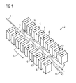
- FIG. 1 schematically shows an undulator system 2 for an electron beam 4 according to the prior art.
- the undulator system 2 is called an insertion device in accelerator physics and usually forms part of a larger installation (here not shown), for example a synchrotron storage ring or a free-electron laser facility.
- the undulator system 2 comprises a periodic structure of dipole magnets 6.
- the static magnetic field generated by this periodic structure is alternating along the length of the undulator system 2 with a periodicity ⁇ u .
- the electron beam 4 traversing this periodic magnet structure is forced to deviate from a central straight electron trajectory 8 thereby undergoing regular oscillations and thus radiating photon beams 10.
- the photon beams 10 produced in the undulator system 2 are very intense and concentrated in narrow energy bands in the spectrum. It is also collimated on the orbit plane of the electron beam.
- the photon beams are guided through beamlines (here not shown) to experiments in various scientific and productive areas, such as semiconductor lithographic applications.
- K eB ⁇ ⁇ 2 ⁇ ⁇ m ⁇ ⁇ c
- e the particle charge
- B the peak magnetic field
- ⁇ ⁇ / c
- m e the electron rest mass
- c the speed of light
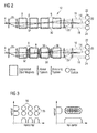
- the present invention provides an undulator system 12 as schematically shown in Figure 2 that splits the electron beam 4 which is provided as electron bunches within the undulator system 12 of a high-gain FEL, resulting in multiple photon beams 14 to 18. These beams 14 to 18 are directed to different user stations 20 to 24.
- the top graph of Figure 2 shows a series of segmented dipole magnets 6 with a first set-up of a fast beam kicker 26 upstream of said series of segmented dipole magnets 6 and a second set-up of a fast beam kicker 28 downstream of said series of segmented dipole magnets 6. It is emphasized at this stage that the second set-up of the fast kicker system 28 is not mandatory to reduce the invention to practice.
- the fast kicker systems 26, 28, which are synchronized with the electron bunches passing by, tilt the straight electron trajectories 8 within the undulator system 12 into the horizontal or vertical directions or in both.
- the fast kicker systems 26, 28 comprise magnetic and/or electric field deflection devices, such as dipole electromagnets, vacuum capacitors, transverse deflecting cavities or the like.
- magnetic and/or electric field deflection devices such as dipole electromagnets, vacuum capacitors, transverse deflecting cavities or the like.
- a bandwidth of several tens of kHz can be achieved using conventional metallic beam pipes.
- special beam pipes can be utilized, for example ceramic vacuum pipes with a thin metallized coating, that reduce Eddy currents. With such kicker systems, bandwidths of many MHz can be achieved. Even faster response times can be provided by resonant electromagnetic circuits or by transversely deflecting structures or cavities.
- the FEL radiation emerges coaxially with the electron beam trajectory 8, 30, 32 within the undulator system 12. Hence, the position of the photon beam 16, 18 at some distance from the undulator system 12 is displaced, enabling a different user station 22, 24 to be installed downstream of the undulator system 12.
- the positional displacement increases linearly with the distance to the undulator system 12.
- the photon beam 16, 18 can be directed simultaneously to multiple user stations 20 to 24 while using only a single undulator 12.
- the same beam splitting scheme achieved by the fast kicker system 26 can be applied if focusing systems 34 for the electron beam 4 are installed between segments of longer dipole magnet lines to improve the FEL performance.
- additional kicker systems 36 near the location of the focusing systems 34 are required, which compensate angular kicks the beam obtains from the focusing elements 34 for various trajectories as shown schematically in the bottom graph of Figure 2 .
- the second setup of the fast kicker system 28 may be utilized to restore the original trajectory of the electron beam if required.
- FIG. 3 Examples of split photon beams at some distance from the undulator system 12 are shown in Figure 3 .
- the left hand panel of Figure 3 shows a pattern of six separated beam spots 38, obtained by synchronously switching the kicker system 26 horizontally and vertically repetitively between the six different states.
- the right hand panel shows a fan-shaped beam resulting from a continuous, horizontal sweep of the kicker system 36, combined with a synchronous single vertical displacement.
- Other distributions of beam spots or continuous beam intensity distributions are possible within certain geometrical constraints and within the parameter regime allowed by the FEL process.
Landscapes
- Physics & Mathematics (AREA)
- Optics & Photonics (AREA)
- Engineering & Computer Science (AREA)
- Plasma & Fusion (AREA)
- Spectroscopy & Molecular Physics (AREA)
- Particle Accelerators (AREA)
Abstract
It is the objective of the present invention to provide an undulator system that provides radiation, preferably synchrotron radiation, with a single undulator to various user stations thereby using an appropriate and simple set up for the undulator system.
A kicker system enables the transfer of the radiation to various user stations by using only one single undulator. The delivery of the radiation to various user stations achieved by deflecting the charged particle beam from its straight particle trajectory is widely controllable by an appropriate steering of the kicker system.
Description
- The present invention relates to a charged particle beam undulator system for generating synchrotron radiation.
- Charged particle beams, in particular in free-electron lasers (FELs), are a flexible tool for generating ultra-bright, coherent radiation with wavelengths ranging from the microwave to the hard x-ray regime. For wavelengths in the vacuum ultra-violet and shorter, high-gain FELs are utilized, in which a bunch train of ultra-relativistic electrons passes through a long undulator for a single time. In the undulator, a periodic arrangement of magnets, synchrotron light is emitted, which interacts with the electron beam in a way that the emitted light power grows exponentially within the undulator until a saturation state is reached. In this state, approximately 10-2 to 10-4 of the kinetic energy of the electron beam is transferred to the photon beam, which is emitted with a narrow spectral bandwidth, a small beam size, and divergence angle.
- The laser-like beam properties and the energy-efficiency in the electron-photon conversion make FELs an interesting tool for providing high power beams at short wavelengths. Combined with a high-power electron accelerator, for example an energy-recovery linear accelerator with the potential of generating a suitable electron beam with tens to hundreds of MW of beam power, photon beams with tens of kW of power in the EUV wavelength range are feasible. Such a machine would, for example, be a possible radiation source for next-generation photolithography applications at wavelengths of 13.5 nm, 6 nm, and shorter.
- Major drawbacks of such a high-power, short-wavelength FEL facility are its costs and its complexity. Besides the high-power electron accelerator, a major cost-driver of such a machine is the long undulator line, which with current techniques only serves radiation to a single customer or user. While it is in principle possible to distribute a high repetition bunch train over multiple undulator beam lines and thus serving multiple users at the same time, this scheme is very expensive, since each user station requires its own undulator beam line. Furthermore, this scheme increases the size of the facility significantly because each beam line requires sufficient separation with an estimated footprint of typically 5 times 30 m2 per beam line.
- It is therefore the objective of the present invention to provide an undulator system that provides radiation, preferably synchrotron radiation, with a single undulator to various user stations thereby using an appropriate and simple set-up for the undulator system.
- This objective is achieved according to the present invention by a charged particle beam undulator system for generating radiation, preferably synchrotron radiation, comprising:
- a) a number of dipole magnets disposed periodically along a straight particle trajectory of said charged particle beam within the undulator;
- b) a kicker system disposed upstream of said number of dipole magnets; wherein
- c) said kicker system comprising a magnet deflection unit and/or an electric field deflection unit being controlled to deflect the charged particle beam from the straight particle trajectory; said straight particle trajectory is given when the kicker system is neutral in terms of deflecting the charged particle beam.
- Therefore, the present kicker system enables the transfer of the radiation to various user stations by using only one single undulator. The delivery of the radiation to various user stations achieved by deflecting the charged particle beam from its straight particle trajectory is widely controllable by an appropriate steering of the kicker system. This results in a broad range of possibilities of a positional and/or an angular offset of the charged particle beam leading to a change in the projected direction or in projected position or a combination of change of direction and position.
- In a preferred embodiment of the present invention, the charged particle beam is part of a free-electron laser (FEL). A free-electron laser for wavelengths in the vacuum ultra-violet and shorter can be realized as a high-gain FEL. The FEL delivers a sufficient yield of synchrotron radiation which enables a transfer of approximately 10-2 to 10-4 of the kinetic energy of the electron beam to the photon beam in its saturation state towards the end of the undulator.
- In order to improve the options for the controlling of the deflected charged particle beam, a further preferred embodiment of the present invention provides for a number of further kicker systems, wherein said number of further kicker systems being disposed between adjacent dipole magnets. In other words, after passing a dipole magnet pair, the charged particle beam can be newly adjusted. Possible set-up could also provide for a separate kicker system for each pair of dipole magnets.
- In some embodiments it could be for example desirable to restore the original trajectory of the electron beam. In order to cope with this demand, a further kicker system is disposed downstream of the number of dipole magnets.
- An appropriate controlling of the kicker system can be achieved when said charged particle beam is discontinuously emitted in a number of bunches, wherein said magnet deflecting unit and/or the electric field deflecting unit is/are controlled to deflect the charged particle beam synchronized to said bunches. One possible option could be realized when this synchronization is effected in terms of a fast switch from one projected direction of the charged particle beam to another projected direction of the charged particle beam during the interval between two bunches of the charged particle beam wherein each projected direction is aligned with a spot of interest for the synchrotron radiation. With each new bunch of charged particle beam coming, the projected direction of the charged particle beam changes. An alternative to this option could be provided when this synchronization is effected in terms of a continuous sweep of the charged particle beam from one projected direction of the charged particle beam to another projected direction of the charged particle beam during an interval of a plurality of bunches of the charged particle beam wherein each projected direction is aligned with a spot of interest for the synchrotron radiation. Therefore, the deflection of the charged particle beam may show a certain (desired) blurring effect when the charged particle beam is shifted from one projected direction into an adjacent projected direction.
- Typically, a spot of interest can be a user station being equipped to use the synchrotron radiation experimentally or in photolithography applications.
- Preferred embodiments of the present invention are described hereinafter in more detail with reference to the attached drawing which depicts in:
- Figure 1
- schematically an undulator for an electron beam according to the prior art;
- Figure 2
- schematically two undulator systems, each comprising at least one kicker system disposed upstream of the magnets of the undulator system; and
- Figure 3
- schematically examples of split photon beam in response to activation of the kicker system as shown in
Figure 2 . -
Figure 1 schematically shows an undulator system 2 for anelectron beam 4 according to the prior art. The undulator system 2 is called an insertion device in accelerator physics and usually forms part of a larger installation (here not shown), for example a synchrotron storage ring or a free-electron laser facility. The undulator system 2 comprises a periodic structure ofdipole magnets 6. The static magnetic field generated by this periodic structure is alternating along the length of the undulator system 2 with a periodicity λ u . Theelectron beam 4 traversing this periodic magnet structure is forced to deviate from a centralstraight electron trajectory 8 thereby undergoing regular oscillations and thus radiatingphoton beams 10. Thephoton beams 10 produced in the undulator system 2 are very intense and concentrated in narrow energy bands in the spectrum. It is also collimated on the orbit plane of the electron beam. The photon beams are guided through beamlines (here not shown) to experiments in various scientific and productive areas, such as semiconductor lithographic applications. - The important dimensionless parameter

where e is the particle charge, B is the peak magnetic field, β = υ/c, me is the electron rest mass and c is the speed of light, characterizes the nature of the electron oscillation. For K<<1 the oscillation amplitude of the motion of theelectron beam 4 is small and the radiation displays interference patterns which lead to narrow energy bands. If K>>1 the oscillation amplitude is bigger and the radiation contributions from each field period sum up independently, leading to a broad energy spectrum. In this regime of fields the insertion device is no longer called an undulator; it is called a wiggler. In this description of the invention and in the sense of the present invention, the word "undulator" is herein used for both operations under either the undulator regime and the wiggler regime. - The present invention provides an
undulator system 12 as schematically shown inFigure 2 that splits theelectron beam 4 which is provided as electron bunches within theundulator system 12 of a high-gain FEL, resulting inmultiple photon beams 14 to 18. Thesebeams 14 to 18 are directed todifferent user stations 20 to 24. - The top graph of
Figure 2 shows a series of segmenteddipole magnets 6 with a first set-up of afast beam kicker 26 upstream of said series of segmenteddipole magnets 6 and a second set-up of a fast beam kicker 28 downstream of said series of segmenteddipole magnets 6. It is emphasized at this stage that the second set-up of thefast kicker system 28 is not mandatory to reduce the invention to practice. Thefast kicker systems straight electron trajectories 8 within theundulator system 12 into the horizontal or vertical directions or in both. - In detail, the
fast kicker systems - In the present example of three
user stations 20 to 24, this leads to a first projectedtrajectory 30 having a positional offset or to a second projectedtrajectory 32 having an angular offset in the electron trajectory, or to these offsets combined, while a third trajectory follows the straightelectron beam trajectory 8 in case thefast kicker system 26 is neutral with respect to a deflection of theincoming electron beam 4. The third or in other words, the central electron trajectory therefore goes straight through to theuser station 20. The FEL radiation emerges coaxially with theelectron beam trajectory undulator system 12. Hence, the position of thephoton beam undulator system 12 is displaced, enabling adifferent user station undulator system 12. For a given angular offset, the positional displacement increases linearly with the distance to theundulator system 12. By switching thefast kicker systems 26 to different settings, each allowing astraight trajectory electron beam 4 through theundulator system 12, thephoton beam multiple user stations - Assuming a certain repetition rate for the accelerator beam and sufficiently fast switching time between the various states of the
fast kicker system 26, thephoton beam multiple user stations 20 to 24 while using only asingle undulator 12. - The same beam splitting scheme achieved by the
fast kicker system 26 can be applied if focusingsystems 34 for theelectron beam 4 are installed between segments of longer dipole magnet lines to improve the FEL performance. In this case,additional kicker systems 36 near the location of the focusingsystems 34 are required, which compensate angular kicks the beam obtains from the focusingelements 34 for various trajectories as shown schematically in the bottom graph ofFigure 2 . - The second setup of the
fast kicker system 28 may be utilized to restore the original trajectory of the electron beam if required. - Examples of split photon beams at some distance from the
undulator system 12 are shown inFigure 3 . The left hand panel ofFigure 3 shows a pattern of six separated beam spots 38, obtained by synchronously switching thekicker system 26 horizontally and vertically repetitively between the six different states. The right hand panel shows a fan-shaped beam resulting from a continuous, horizontal sweep of thekicker system 36, combined with a synchronous single vertical displacement. Other distributions of beam spots or continuous beam intensity distributions are possible within certain geometrical constraints and within the parameter regime allowed by the FEL process. - The above schemes rely on the fact that all
electron trajectories
Claims (8)
- A charged particle beam undulator system (12) for generating synchrotron radiation (14 to 18), comprising:a) a number of dipole magnets (6) disposed periodically along a straight particle trajectory (8) of said charged particle beam (4) within the undulator system(12);b) a kicker system (26) disposed upstream of said number of dipole magnets (6); whereinc) said kicker system (26) comprising a magnet deflection unit and/or an electric field deflection unit being controlled to deflect the charged particle beam (4) from the straight particle trajectory (8); said straight particle trajectory (8) is given when the kicker system (26) is neutral in terms of deflecting the charged particle beam (4).
- The undulator system (12) according to claim 1, wherein the charged particle beam (4) is a free-electron laser.
- The undulator system (12) according to claim 1 or 2, wherein a number of further kicker systems (36) is provided, said number of further kicker system (36) being disposed between adjacent dipole magnets (6) or adjacent groups of dipole magnets (6).
- The undulator system (12) according to any of the preceding claims 1 to 3, wherein a further kicker system (28) is disposed downstream of the number of dipole magnets (6).
- The undulator system (12) according to any of the preceding claims 1 to 4, wherein said charged particle beam (4) is discontinuously emitted in a number of bunches, wherein said magnet deflecting unit and/or the electric field deflecting unit is/are controlled to deflect the charged particle beam synchronized to said bunches.
- The undulator system (12) according to claim 5 wherein the synchronization is effected in terms of a fast switch from one projected direction of the charged particle beam to another projected direction of the charged particle beam during the interval between two bunches of the charged particle beam wherein each projected direction is aligned with a spot of interest (20 to 24) for the synchrotron radiation (14 to 18).
- The undulator system (12) according to claim 5 wherein the synchronization is effected in terms of a continuous sweep of the charged particle beam (4) from one projected direction of the charged particle beam to another projected direction of the charged particle beam during an interval of a plurality of bunches of the charged particle beam (4) wherein each projected direction is aligned with a spot of interest (20 to 24) for the synchrotron radiation (14 to 18).
- The undulator system according to any of the preceding claims wherein a spot of interest is a user station (20 to 24), said user station (20 to 24) being equipped to use the synchrotron radiation (14 to 18) experimentally or in photolithography applications.
Priority Applications (2)
| Application Number | Priority Date | Filing Date | Title |
|---|---|---|---|
| EP13191927.6A EP2806715A1 (en) | 2013-05-23 | 2013-11-07 | Beam splitter for FEL undulator |
| PCT/EP2014/056580 WO2014187603A1 (en) | 2013-05-23 | 2014-04-02 | Beam splitter for fel undulator |
Applications Claiming Priority (2)
| Application Number | Priority Date | Filing Date | Title |
|---|---|---|---|
| EP13168966 | 2013-05-23 | ||
| EP13191927.6A EP2806715A1 (en) | 2013-05-23 | 2013-11-07 | Beam splitter for FEL undulator |
Publications (1)
| Publication Number | Publication Date |
|---|---|
| EP2806715A1 true EP2806715A1 (en) | 2014-11-26 |
Family
ID=49553560
Family Applications (1)
| Application Number | Title | Priority Date | Filing Date |
|---|---|---|---|
| EP13191927.6A Withdrawn EP2806715A1 (en) | 2013-05-23 | 2013-11-07 | Beam splitter for FEL undulator |
Country Status (2)
| Country | Link |
|---|---|
| EP (1) | EP2806715A1 (en) |
| WO (1) | WO2014187603A1 (en) |
Cited By (1)
| Publication number | Priority date | Publication date | Assignee | Title |
|---|---|---|---|---|
| CN106954333A (en) * | 2017-03-28 | 2017-07-14 | 中国科学院上海光学精密机械研究所 | Multifunctional focusing device and method of use of laser plasma accelerated electron beam source |
-
2013
- 2013-11-07 EP EP13191927.6A patent/EP2806715A1/en not_active Withdrawn
-
2014
- 2014-04-02 WO PCT/EP2014/056580 patent/WO2014187603A1/en not_active Ceased
Non-Patent Citations (3)
| Title |
|---|
| F.J.DECKER ET AL: "Multiple FELS from the One LCLS Undulator", PROCEEDINGS OF FEL 2011, August 2011 (2011-08-01), pages 629 - 632, XP002727436, ISBN: 978-3-95450-117-5 * |
| R.BRINKMANN ET AL: "Betatron Switcher for a Multi-color Operation of an X-Ray FEL", PROCEEDINGS OF FEL 2010, April 2011 (2011-04-01), pages 127 - 130, XP002727434 * |
| R.BRINKMANN ET AL: "Possible Operation of the European XFEL with Ultra-low Emittance Beams", NUCLEAR INSTRUMENTS AND METHODS IN PHYSICS RESEARCH A, vol. 616, 26 February 2010 (2010-02-26), pages 81 - 87, XP002727435 * |
Cited By (2)
| Publication number | Priority date | Publication date | Assignee | Title |
|---|---|---|---|---|
| CN106954333A (en) * | 2017-03-28 | 2017-07-14 | 中国科学院上海光学精密机械研究所 | Multifunctional focusing device and method of use of laser plasma accelerated electron beam source |
| CN106954333B (en) * | 2017-03-28 | 2018-11-20 | 中国科学院上海光学精密机械研究所 | The multi-functional focusing device and application method in laser plasma accelerated electron beam source |
Also Published As
| Publication number | Publication date |
|---|---|
| WO2014187603A1 (en) | 2014-11-27 |
Similar Documents
| Publication | Publication Date | Title |
|---|---|---|
| KR102340172B1 (en) | Free electron laser radiation source for the euv | |
| JP6417418B2 (en) | Electron injector, free electron laser, lithography system, electron beam generation method, and radiation generation method | |
| EP2158796A1 (en) | Beam transport system and method for linear accelerators | |
| US20020186814A1 (en) | Star pinch X-ray and extreme ultraviolet photon source | |
| US10381796B2 (en) | Free electron laser | |
| Eckey et al. | Strong-field Breit-Wheeler pair production with bremsstrahlung γ rays in the perturbative-to-nonperturbative-transition regime | |
| US10736205B2 (en) | Electron beam transport system | |
| EP2806715A1 (en) | Beam splitter for FEL undulator | |
| US10468225B2 (en) | Electron source for a free electron laser | |
| US9648713B2 (en) | High-gain thompson-scattering X-ray free-electron laser by time-synchronic laterally tilted optical wave | |
| WO2017076696A1 (en) | Electron beam chopper | |
| WO2017092943A1 (en) | Free electron laser | |
| NL2017991A (en) | Apparatus and Method for Producing a Beam of Electron Bunches | |
| Hillenbrand | Study of plasma-based acceleration for high energy physics and other applications | |
| Leach | The free electron laser, offspring of synchrotron radiation | |
| WO2017071878A1 (en) | Electron source, with photocathode illuminated off-axis | |
| Socol et al. | 13.5 nm free-electron laser for EUV lithography | |
| Huang et al. | A DIELECTRIC-BASED | |
| Song et al. | Bandwidth broadening of X-ray free electron laser with the natural gradient of planar undulator | |
| Cossairt | Accelerator and beam physics for health physicists | |
| CN110859019A (en) | Oscillator and laser plasma X-ray source including the same |
Legal Events
| Date | Code | Title | Description |
|---|---|---|---|
| PUAI | Public reference made under article 153(3) epc to a published international application that has entered the european phase |
Free format text: ORIGINAL CODE: 0009012 |
|
| 17P | Request for examination filed |
Effective date: 20131107 |
|
| AK | Designated contracting states |
Kind code of ref document: A1 Designated state(s): AL AT BE BG CH CY CZ DE DK EE ES FI FR GB GR HR HU IE IS IT LI LT LU LV MC MK MT NL NO PL PT RO RS SE SI SK SM TR |
|
| AX | Request for extension of the european patent |
Extension state: BA ME |
|
| STAA | Information on the status of an ep patent application or granted ep patent |
Free format text: STATUS: THE APPLICATION IS DEEMED TO BE WITHDRAWN |
|
| 18D | Application deemed to be withdrawn |
Effective date: 20150527 |