EP2806593A1 - Method and apparatus for transmitting uplink control information in wireless communication system - Google Patents
Method and apparatus for transmitting uplink control information in wireless communication system Download PDFInfo
- Publication number
- EP2806593A1 EP2806593A1 EP13739031.6A EP13739031A EP2806593A1 EP 2806593 A1 EP2806593 A1 EP 2806593A1 EP 13739031 A EP13739031 A EP 13739031A EP 2806593 A1 EP2806593 A1 EP 2806593A1
- Authority
- EP
- European Patent Office
- Prior art keywords
- ack
- nack
- pucch format
- csi
- pdcch
- Prior art date
- Legal status (The legal status is an assumption and is not a legal conclusion. Google has not performed a legal analysis and makes no representation as to the accuracy of the status listed.)
- Granted
Links
- 238000000034 method Methods 0.000 title claims abstract description 174
- 238000004891 communication Methods 0.000 title claims abstract description 31
- 101000741965 Homo sapiens Inactive tyrosine-protein kinase PRAG1 Proteins 0.000 claims abstract description 162
- 102100038659 Inactive tyrosine-protein kinase PRAG1 Human genes 0.000 claims abstract description 162
- 230000005540 biological transmission Effects 0.000 claims description 248
- 230000004044 response Effects 0.000 claims description 40
- 102100036409 Activated CDC42 kinase 1 Human genes 0.000 description 122
- 230000000875 corresponding effect Effects 0.000 description 63
- 239000010410 layer Substances 0.000 description 55
- 230000000737 periodic effect Effects 0.000 description 45
- 230000002776 aggregation Effects 0.000 description 30
- 238000004220 aggregation Methods 0.000 description 30
- 230000032258 transport Effects 0.000 description 20
- 239000000969 carrier Substances 0.000 description 16
- 238000013468 resource allocation Methods 0.000 description 12
- 230000004913 activation Effects 0.000 description 11
- 230000015654 memory Effects 0.000 description 9
- 230000008569 process Effects 0.000 description 9
- 230000004931 aggregating effect Effects 0.000 description 6
- 238000005516 engineering process Methods 0.000 description 6
- 238000013507 mapping Methods 0.000 description 6
- 230000009849 deactivation Effects 0.000 description 5
- 230000006870 function Effects 0.000 description 5
- 230000007480 spreading Effects 0.000 description 5
- 125000004122 cyclic group Chemical group 0.000 description 4
- 230000003247 decreasing effect Effects 0.000 description 4
- 230000009977 dual effect Effects 0.000 description 4
- 239000011159 matrix material Substances 0.000 description 4
- 230000011664 signaling Effects 0.000 description 4
- 230000006978 adaptation Effects 0.000 description 3
- 238000007726 management method Methods 0.000 description 3
- 238000012545 processing Methods 0.000 description 3
- 230000001960 triggered effect Effects 0.000 description 3
- 230000000052 comparative effect Effects 0.000 description 2
- 238000001514 detection method Methods 0.000 description 2
- 238000010586 diagram Methods 0.000 description 2
- 238000005259 measurement Methods 0.000 description 2
- 230000010363 phase shift Effects 0.000 description 2
- 238000010187 selection method Methods 0.000 description 2
- 230000002123 temporal effect Effects 0.000 description 2
- 208000017227 ADan amyloidosis Diseases 0.000 description 1
- 101150001149 CSI1 gene Proteins 0.000 description 1
- 201000000194 ITM2B-related cerebral amyloid angiopathy 2 Diseases 0.000 description 1
- AEMOLEFTQBMNLQ-DOTFUZMJSA-N L-Alturonic Acid Chemical compound OC1O[C@@H](C(O)=O)[C@H](O)[C@H](O)[C@H]1O AEMOLEFTQBMNLQ-DOTFUZMJSA-N 0.000 description 1
- 108700026140 MAC combination Proteins 0.000 description 1
- 102100040255 Tubulin-specific chaperone C Human genes 0.000 description 1
- 230000000295 complement effect Effects 0.000 description 1
- 230000001276 controlling effect Effects 0.000 description 1
- 230000002596 correlated effect Effects 0.000 description 1
- 239000002355 dual-layer Substances 0.000 description 1
- 230000000694 effects Effects 0.000 description 1
- 238000005562 fading Methods 0.000 description 1
- PCHJSUWPFVWCPO-UHFFFAOYSA-N gold Chemical group [Au] PCHJSUWPFVWCPO-UHFFFAOYSA-N 0.000 description 1
- 230000010354 integration Effects 0.000 description 1
- 230000007774 longterm Effects 0.000 description 1
- 230000007257 malfunction Effects 0.000 description 1
- 238000010295 mobile communication Methods 0.000 description 1
- 238000012544 monitoring process Methods 0.000 description 1
- 230000011218 segmentation Effects 0.000 description 1
- 238000001774 stimulated Raman spectroscopy Methods 0.000 description 1
- 229920006344 thermoplastic copolyester Polymers 0.000 description 1
- 230000007704 transition Effects 0.000 description 1
- 108010093459 tubulin-specific chaperone C Proteins 0.000 description 1
Images


Classifications
-
- H—ELECTRICITY
- H04—ELECTRIC COMMUNICATION TECHNIQUE
- H04L—TRANSMISSION OF DIGITAL INFORMATION, e.g. TELEGRAPHIC COMMUNICATION
- H04L1/00—Arrangements for detecting or preventing errors in the information received
- H04L1/12—Arrangements for detecting or preventing errors in the information received by using return channel
- H04L1/16—Arrangements for detecting or preventing errors in the information received by using return channel in which the return channel carries supervisory signals, e.g. repetition request signals
- H04L1/18—Automatic repetition systems, e.g. Van Duuren systems
-
- H—ELECTRICITY
- H04—ELECTRIC COMMUNICATION TECHNIQUE
- H04W—WIRELESS COMMUNICATION NETWORKS
- H04W72/00—Local resource management
- H04W72/20—Control channels or signalling for resource management
- H04W72/21—Control channels or signalling for resource management in the uplink direction of a wireless link, i.e. towards the network
-
- H—ELECTRICITY
- H04—ELECTRIC COMMUNICATION TECHNIQUE
- H04L—TRANSMISSION OF DIGITAL INFORMATION, e.g. TELEGRAPHIC COMMUNICATION
- H04L1/00—Arrangements for detecting or preventing errors in the information received
- H04L1/0001—Systems modifying transmission characteristics according to link quality, e.g. power backoff
- H04L1/0023—Systems modifying transmission characteristics according to link quality, e.g. power backoff characterised by the signalling
- H04L1/0026—Transmission of channel quality indication
-
- H—ELECTRICITY
- H04—ELECTRIC COMMUNICATION TECHNIQUE
- H04L—TRANSMISSION OF DIGITAL INFORMATION, e.g. TELEGRAPHIC COMMUNICATION
- H04L1/00—Arrangements for detecting or preventing errors in the information received
- H04L1/12—Arrangements for detecting or preventing errors in the information received by using return channel
- H04L1/16—Arrangements for detecting or preventing errors in the information received by using return channel in which the return channel carries supervisory signals, e.g. repetition request signals
- H04L1/1607—Details of the supervisory signal
- H04L1/1671—Details of the supervisory signal the supervisory signal being transmitted together with control information
-
- H—ELECTRICITY
- H04—ELECTRIC COMMUNICATION TECHNIQUE
- H04L—TRANSMISSION OF DIGITAL INFORMATION, e.g. TELEGRAPHIC COMMUNICATION
- H04L1/00—Arrangements for detecting or preventing errors in the information received
- H04L1/12—Arrangements for detecting or preventing errors in the information received by using return channel
- H04L1/16—Arrangements for detecting or preventing errors in the information received by using return channel in which the return channel carries supervisory signals, e.g. repetition request signals
- H04L1/1607—Details of the supervisory signal
- H04L1/1692—Physical properties of the supervisory signal, e.g. acknowledgement by energy bursts
-
- H—ELECTRICITY
- H04—ELECTRIC COMMUNICATION TECHNIQUE
- H04L—TRANSMISSION OF DIGITAL INFORMATION, e.g. TELEGRAPHIC COMMUNICATION
- H04L1/00—Arrangements for detecting or preventing errors in the information received
- H04L1/12—Arrangements for detecting or preventing errors in the information received by using return channel
- H04L1/16—Arrangements for detecting or preventing errors in the information received by using return channel in which the return channel carries supervisory signals, e.g. repetition request signals
- H04L1/18—Automatic repetition systems, e.g. Van Duuren systems
- H04L1/1829—Arrangements specially adapted for the receiver end
- H04L1/1861—Physical mapping arrangements
-
- H—ELECTRICITY
- H04—ELECTRIC COMMUNICATION TECHNIQUE
- H04L—TRANSMISSION OF DIGITAL INFORMATION, e.g. TELEGRAPHIC COMMUNICATION
- H04L1/00—Arrangements for detecting or preventing errors in the information received
- H04L1/12—Arrangements for detecting or preventing errors in the information received by using return channel
- H04L1/16—Arrangements for detecting or preventing errors in the information received by using return channel in which the return channel carries supervisory signals, e.g. repetition request signals
- H04L1/18—Automatic repetition systems, e.g. Van Duuren systems
- H04L1/1867—Arrangements specially adapted for the transmitter end
- H04L1/1896—ARQ related signaling
-
- H—ELECTRICITY
- H04—ELECTRIC COMMUNICATION TECHNIQUE
- H04L—TRANSMISSION OF DIGITAL INFORMATION, e.g. TELEGRAPHIC COMMUNICATION
- H04L5/00—Arrangements affording multiple use of the transmission path
- H04L5/003—Arrangements for allocating sub-channels of the transmission path
- H04L5/0053—Allocation of signaling, i.e. of overhead other than pilot signals
- H04L5/0055—Physical resource allocation for ACK/NACK
-
- H—ELECTRICITY
- H04—ELECTRIC COMMUNICATION TECHNIQUE
- H04L—TRANSMISSION OF DIGITAL INFORMATION, e.g. TELEGRAPHIC COMMUNICATION
- H04L5/00—Arrangements affording multiple use of the transmission path
- H04L5/003—Arrangements for allocating sub-channels of the transmission path
- H04L5/0053—Allocation of signaling, i.e. of overhead other than pilot signals
- H04L5/0057—Physical resource allocation for CQI
-
- H—ELECTRICITY
- H04—ELECTRIC COMMUNICATION TECHNIQUE
- H04L—TRANSMISSION OF DIGITAL INFORMATION, e.g. TELEGRAPHIC COMMUNICATION
- H04L5/00—Arrangements affording multiple use of the transmission path
- H04L5/14—Two-way operation using the same type of signal, i.e. duplex
-
- H—ELECTRICITY
- H04—ELECTRIC COMMUNICATION TECHNIQUE
- H04L—TRANSMISSION OF DIGITAL INFORMATION, e.g. TELEGRAPHIC COMMUNICATION
- H04L1/00—Arrangements for detecting or preventing errors in the information received
- H04L1/0001—Systems modifying transmission characteristics according to link quality, e.g. power backoff
- H04L1/0023—Systems modifying transmission characteristics according to link quality, e.g. power backoff characterised by the signalling
- H04L1/0028—Formatting
- H04L1/0031—Multiple signaling transmission
-
- H—ELECTRICITY
- H04—ELECTRIC COMMUNICATION TECHNIQUE
- H04L—TRANSMISSION OF DIGITAL INFORMATION, e.g. TELEGRAPHIC COMMUNICATION
- H04L1/00—Arrangements for detecting or preventing errors in the information received
- H04L1/004—Arrangements for detecting or preventing errors in the information received by using forward error control
- H04L1/0072—Error control for data other than payload data, e.g. control data
- H04L1/0073—Special arrangements for feedback channel
-
- H—ELECTRICITY
- H04—ELECTRIC COMMUNICATION TECHNIQUE
- H04L—TRANSMISSION OF DIGITAL INFORMATION, e.g. TELEGRAPHIC COMMUNICATION
- H04L1/00—Arrangements for detecting or preventing errors in the information received
- H04L1/12—Arrangements for detecting or preventing errors in the information received by using return channel
- H04L1/16—Arrangements for detecting or preventing errors in the information received by using return channel in which the return channel carries supervisory signals, e.g. repetition request signals
- H04L1/1607—Details of the supervisory signal
- H04L1/1614—Details of the supervisory signal using bitmaps
-
- H—ELECTRICITY
- H04—ELECTRIC COMMUNICATION TECHNIQUE
- H04L—TRANSMISSION OF DIGITAL INFORMATION, e.g. TELEGRAPHIC COMMUNICATION
- H04L5/00—Arrangements affording multiple use of the transmission path
- H04L5/0001—Arrangements for dividing the transmission path
- H04L5/0014—Three-dimensional division
- H04L5/0023—Time-frequency-space
-
- H—ELECTRICITY
- H04—ELECTRIC COMMUNICATION TECHNIQUE
- H04W—WIRELESS COMMUNICATION NETWORKS
- H04W72/00—Local resource management
- H04W72/20—Control channels or signalling for resource management
- H04W72/23—Control channels or signalling for resource management in the downlink direction of a wireless link, i.e. towards a terminal
Definitions
- the present invention relates to wireless communication, and more particularly, to a method and an apparatus for transmitting uplink control information in a wireless communication system.
- OFDM orthogonal frequency division multiplexing
- ISI inter-symbol interference
- a data symbol input in series is converted into N parallel data symbols which are loaded on N separated subcarriers to be transmitted, respectively.
- the subcarriers maintain orthogonality in respect of a frequency.
- Respective orthogonal channels undergo independent frequency selective fading, and as a result, complexity in a receiver is decreased and an interval of transmitted symbols is increased to minimize inter-symbol interference.
- Orthogonal frequency division multiple access represents a multiple access method that implements a multiple access by independently some of usable subcarriers to each user in a system using the OFDM as a modulation scheme.
- the OFDMA provides frequency resources such as the subcarriers to each user and the respective frequency resources are independently provided to a plurality of users not to be overlapped with each other, in general. Consequently, the frequency resources are exclusively allocated for each user.
- frequency diversity for multiple users may be acquired through frequency selective scheduling and the subcarriers may be allocated in various patterns according to a permutation scheme for the subcarriers.
- efficiency of a spatial area may be increased by a space multiplexing technique using multiple antennas.
- MIMO Multiple-input multiple-output
- a technique for implementing diversity in an MIMO system includes a space frequency block code (SFBC), a space time block code (STBC), cyclic delay diversity (CDD), frequency switched transmit diversity (FSTD), time switched transmit diversity (TSTD), precoding vector switching (PVS), spatial multiplexing (SM), and the like.
- An MIMO channel matrix depending on the number of receiving antennas and the number of transmitting antennas may be dissolved into a plurality of independent channels.
- the respective independent channels are called layers or streams.
- the number of layers represents a rank.
- Uplink control information may be transmitted through a physical uplink control channel (PUCCH).
- the uplink control information may include various types of information including a scheduling request (SR), an acknowledgement/non-acknowledgement (ACK/NACK) signal, a channel quality indicator (CQI), a precoding matrix indicator (PMI), a rank indicator (RI), and the like.
- SR scheduling request
- ACK/NACK acknowledgement/non-acknowledgement
- CQI channel quality indicator
- PMI precoding matrix indicator
- RI rank indicator
- the PUCCH transports various types of control information according to a format.
- the carrier aggregation system means a system that configures a wideband by collecting one or more subcarriers having a smaller bandwidth than a target wideband when the wireless communication system supports the wideband.
- the present invention provides a method and an apparatus for transmitting uplink control information in a wireless communication system.
- a method for transmitting uplink control information (UCI) performed by user equipment in a wireless communication system includes: receiving a first parameter for indicating whether to simultaneously transmit a first combination of an acknowledgment/no-acknowledgement (ACK/NACK) and a channel quality indicator (CQI) and a second parameter for indicating whether to multiplex a second combination of an ACK/NACK and the CQI and transmit the multiplexed second combination in a second physical uplink control channel (PUCCH) format; and multiplexing the first combination of the ACK/NACK or the second combination of the ACK/NACK with the CQI and transmitting the multiplexed ACK/NACK and CQI through a first PUCCH format or the second PUCCH format.
- ACK/NACK acknowledgment/no-acknowledgement
- CQI channel quality indicator
- PUCCH physical uplink control channel
- a user equipment in another aspect, includes: method includes: a radio frequency (RF) unit transmitting or receiving a radio signal; and a processor connected with the RF unit, wherein the processors receives a first parameter for indicating whether to simultaneously transmit a first combination of an acknowledgment/no-acknowledgement (ACK/NACK) and a channel quality indicator (CQI) and a second parameter for indicating whether to multiplex a second combination of an ACK/NACK and the CQI and transmit the multiplexed second combination in a second physical uplink control channel (PUCCH) format, and multiplexes the first combination of the ACK/NACK or the second combination of the ACK/NACK with the CQI and transmits the multiplexed ACK/NACK and CQI through a first PUCCH format or the second PUCCH format.
- RF radio frequency
- the uplink control information may be efficiently multiplexed and transmitted.
- CDMA code division multiple access
- FDMA frequency division multiple access
- TDMA time division multiple access
- OFDMA orthogonal frequency division multiple access
- SC-FDMA single carrier-FDMA
- the CDMA may be implemented by radio technology universal terrestrial radio access (UTRA) or CDMA2000.
- the TDMA may be implemented by radio technology such as Global System for Mobile communications (GSM)/General Packet Radio Service(GPRS)/Enhanced Data Rates for GSM Evolution (EDGE).
- GSM Global System for Mobile communications
- GPRS General Packet Radio Service
- EDGE Enhanced Data Rates for GSM Evolution
- the OFDMA may be implemented as radio technology such as IEEE 802.11(Wi-Fi), IEEE 802.16(WiMAX), IEEE 802-20, E-UTRA(Evolved UTRA), and the like.
- IEEE 802.16m as the evolution of IEEE 802.16e provides backward compatibility with a system based on the IEEE 802.16e.
- the UTRA is a part of a universal mobile telecommunication system (UMTS).
- 3 rd generation partnership project (3GPP) long term evolution (LTE) as a part of an evolved UMTS (E-UMTS) using evolved-UMTS terrestrial radio access (E-UTRA) adopts the OFDMA in a downlink and the SC-FDMA in an uplink.
- LTE-advanced (A) is an evolution of the 3GPP LTE.
- the LTE/LTE-A is primarily described for clear description, but the spirit of the present invention is not limited thereto.
- the wireless communication system includes at least one base station (BS). Each base station provides a communication service to a specific geographical region.
- User equipment may be fixed or movable and may be called other terms such as a mobile station (MS), a mobile terminal (MT), a user terminal (UT), a subscriber station (SS), a wireless device, a personal digital assistant (PDA), a wireless modem, a handheld device, and the like.
- the base station generally represents a fixed station that communicates with a terminal, and may be called different terms such as an evolved-NodeB (eNB), a base transceiver system (BTS), an access point, and the like.
- eNB evolved-NodeB
- BTS base transceiver system
- access point and the like.
- the user equipment generally belongs to one cell and the cell to which the terminal belongs is referred to as a serving cell.
- a base station that provides the communication service to the serving cell is referred to as a serving BS.
- the serving base station may provide one or a plurality of serving cells.
- the technology may be used in a downlink or an uplink.
- the downlink means communication from the base station to the terminal and the uplink means communication from the terminal to the base station.
- Layers of a radio interface protocol between the terminal and the base station may be divided into a first layer (L1), a second layer (L2), and a third layer (L3) based on three lower layers of an open system interconnection (OSI) model which is widely known in a communication system.
- OSI open system interconnection
- a physical layer as the first layer is connected with a medium access control (MAC) layer which is a higher layer through a transport channel and data moves between the MAC layer and the physical layer through the transport channel.
- MAC medium access control
- data moves between different physical layers, that is, between physical layers at a transmitter and a receiver through a physical channel.
- a radio data link layer as the second layer is constituted by the MAC layer, an RLC layer, and a PDCP layer.
- the MAC layer as a layer that takes charge of mapping a logic channel and the transport channel selects an appropriate transport channel in order to transmit data transferred from the RLC layer and adds required control information to a header of an MAC protocol data unit (PDU).
- PDU MAC protocol data unit
- the RLC layer is positioned on a layer upper than the MAC layer to support reliable transmission of data. Further, the RLC layer segments and concatenates RLC service data units (SDUs) transferred from the higher layer in order to configure data having an appropriate size suitable for a radio interval.
- SDUs RLC service data units
- the RLC layer of a receiver supports a reassembling function of data in order to restore an original RLC SDU from the received RLC PDUs.
- the PDCP layer is used only in a packet exchange area and a header of an IP packet may be compressed and transmitted so as to increase transmission efficiency of packet data in a radio channel.
- the RRC layer as the third layer serves to control a lower layer and exchanges radio resource control information between the user equipment and a network.
- Various RRC statuses including an idle mode an RRC connected mode, and the like are defined according to a communication status of the user equipment and transition between the RRC statuses is possible as necessary.
- various procedures associated with radio resource management are defined, which include system information broadcasting, an RRC access management procedure, a multiple component carrier configuring procedure, a radio bearer controlling procedure, a security procedure, a measurement procedure, a mobility management procedure (handover), and the like.
- the wireless communication system may be any one of a multiple-input multiple-output (MIMO) system, a multiple-input single-output (MISO) system, a single-input single-output (SISO) system, and a single-input multiple-output (SIMO) system.
- MIMO multiple-input multiple-output
- MISO multiple-input single-output
- SISO single-input single-output
- SIMO single-input multiple-output
- the MIMO system uses a plurality of transmit antennas and a plurality of receive antennas.
- the MISO system uses a plurality of antennas and one receive antenna.
- the SISO system uses one antenna and one receive antenna.
- the SIMO system uses one transmit antenna and one receive antenna.
- the transmit antenna means a physical or logical antenna used to transmit one signal or stream
- the receive antenna means a physical or logical antenna used to receive one signal or stream.
- FIG. 1 illustrates a structure of a radio frame in 3GPP LTE.
- the radio frame is constituted by 10 subframes and one subframe is constituted by 2 slots. Slots in the radio frame are numbered with slots numbers of #0 to #19. A time required to transmit one subframe is referred to as a transmission time interval (TTI).
- the TTI may be a scheduling unit for data transmission.
- the length of one frame may be 10 ms
- the length of one subframe may be 1 ms
- the length of one slot may be 0.5 ms.
- One slot includes a plurality of orthogonal frequency division multiplexing (OFDM) symbols in a time domain and includes a plurality of subcarriers in a frequency domain. Since the 3GPP LTE uses the OFDMA in the downlink, the OFDM symbol is used to express one symbol period and may be called other name according to a multiple access scheme. For example, when SC-FDMA is used as an uplink multiple access scheme, the OFDM symbol may be called an SC-FDMA symbol.
- a resource block (RB) includes a plurality of contiguous subcarriers in one slot as a resource allocation unit.
- the structure of the radio frame is just one example. Accordingly, the number of subframes included in the radio frame, the number of slots included in the subframe, or the number of OFDM symbols included in the slot may be variously changed.
- the 3GPP LTE defines that one slot includes 7 OFDM symbols in a normal cyclic prefix (CP) and one slot includes 6 OFDM symbols in an extended CP.
- CP normal cyclic prefix
- the wireless communication system may be generally divided into a frequency division duplex (FDD) scheme and a time division duplex (TDD) scheme.
- FDD frequency division duplex
- TDD time division duplex
- uplink transmission and downlink transmission are performed while occupying different frequency bands.
- the uplink transmission and the downlink transmission are performed at different timings while occupying the same frequency band.
- a channel response of the TDD scheme is substantially reciprocal. This means that a downlink channel response and an uplink channel response are almost the same as each other in a given frequency domain. Accordingly, in the wireless communication system based on the TDD, the downlink channel response may be acquired from the uplink channel response.
- the downlink transmission by the base station and the uplink transmission by the terminal may not simultaneously be performed.
- the uplink transmission and the downlink transmission are performed in different subframes.
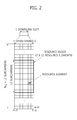
- FIG. 2 illustrates one example of a resource grid for one downlink slot.
- the downlink slot includes a plurality of OFDM symbols in the time domain and includes N RB resource blocks in the frequency domain.
- the number N RB of resource blocks included in the downlink slot is subordinate to a downlink bandwidth N DL set in a cell.
- N RB may be any one of 6 to 110.
- One resource block includes a plurality of subcarriers in the frequency domain.
- a structure of an uplink slot may also be the same as that of the downlink slot.
- Each element on the resource grid is called a resource element (RE).
- the resource element on the resource grid may be identified by a pair of indexes (k,l) in the slot.
- one resource block is constituted by 7 OFDM symbols in the time domain and 12 subcarriers in the frequency domain and thus includes 7 x 12 resource elements, but the number of the OFDM symbols and the number of the subcarriers in the resource block are not limited thereto.
- the number of the OFDM symbols and the number of the subcarriers may be variously changed depending on the length of a CP, frequency spacing, and the like. For example, in the case of a normal CP, the number of OFDM symbols is 7 and in the case of an extended CP, the number of OFDM symbols is 6.
- the number of subcarriers in one OFDM symbol one may be selected and used among 128, 256, 512, 1024, 1536, and 2048.
- FIG. 3 illustrates a structure of a downlink subframe.
- the downlink subframe includes two slots in the time domain and each slot includes seven OFDM symbols in the normal CP. Preceding maximum 3 OFDM symbols (maximum 4 OFDM symbols for a 1.4 Mhz bandwidth) of a first slot in the subframe are a control region to which control channels are allocated and residual OFDM symbols become a data region to which a physical downlink shared channel (PDSCH) is allocated.
- PDSCH physical downlink shared channel
- a PUCCH may transport resource allocation and a transmission format of a downlink-shared channel, resource allocation information of an uplink shared channel, paging information on a PCH, system information on the DL-SCH, resource allocation of a higher layer control message such as a random access response transmitted on the PDSCH, a set of transmission power control commands for individual UEs in a predetermined UE group, and activation of voice over Internet protocol (VoIP).
- a plurality of PDCCHs may be transmitted in the control region and the terminal may monitor the plurality of PDCCHs.
- the PDCCH is transmitted on aggregation of one or several contiguous control channel elements (CCEs).
- CCEs contiguous control channel elements
- the CCE is a logical allocation unit used to provide to the PDCCH coding rate depending on a state of a radio channel.
- the CCEs correspond to a plurality of resource element groups.
- a format of the PDCCH and the bit number of an available PDCCH are determined according to a correlation of the number of CCEs and the coding rate provided by the CCEs.
- the base station determines the PDCCH format according to the downlink control information (DCI) to be sent to the terminal and affixes a cyclic redundancy check (CRC) to the control information.
- a unique identifier (radio network temporary identifier (RNTI)) is masked on the CRC according to an owner or a purpose of the PDCCH.
- RNTI radio network temporary identifier
- a unique identifier of the terminal for example, a cell (C)-RNTI may be masked on the CRC.
- a paging indication identifier for example, a paging (P)-RNTI may be masked on the CRC.
- a system information (SI)-RNTI may be masked on the CRC.
- a random access (RA)-RNTI may be masked on the CRC in order to indicate the random access response which is a response to transmission of a random access preamble of the terminal.
- FIG. 4 illustrates a structure of an uplink subframe.
- the uplink subframe may be divided into a control region and a data region in the frequency domain.
- the physical uplink control channel (PUCCH) for transmitting the uplink control information is allocated to the control region.
- the physical uplink shared channel (PUSCH) for transmitting data is allocated to the data region.
- the terminal may support simultaneous transmission of the PUSCH and the PUCCH.
- a PUCCH for one terminal is allocated to a resource block pair in the subframe.
- Resource blocks that belong to the resource block pair occupy different subcarriers in first and second slots, respectively.
- a frequency occupied by the resource block that belongs to the resource block pair allocated to the PUCCH is changed based on a slot boundary. This means that the RB pair allocated to the PUCCH is frequency-hopped on the slot boundary.
- the terminal transmits the uplink control information through different subcarriers with time to acquire a frequency diversity gain.
- the PUSCH is mapped to the uplink shared channel (UL-SCH) which is a transport channel.
- Uplink data transmitted on the PUSCH may be a transport block which is a data block for the UL-SCH transmitted during the TTI.
- the transport block may be user information.
- the uplink data may be multiplexed data.
- the multiplexed data may be acquired by multiplexing the transport block for the UL-SCH and the uplink control information (UCI).
- UCI uplink control information
- the uplink control information multiplexed to data may include a channel quality indicator (CQI), a precoding matrix indicator (PMI), hybrid automatic repeat request acknowledgement/not-acknowledgement (HARQ-ACK/NACK) (may be represented as HARQ-ACK or simply represented by A/N), a rank indicator (RI), and the like.
- CQI channel quality indicator
- PMI precoding matrix indicator
- HARQ-ACK/NACK hybrid automatic repeat request acknowledgement/not-acknowledgement
- RI rank indicator
- the uplink data may be constituted by only the uplink control information.
- the wireless communication system may support carrier aggregation (CA).
- CA carrier aggregation
- the carrier aggregation means collecting a plurality of carriers having a small bandwidth to configure a wide band.
- the carrier aggregation system means a system that configures the wide band by collecting one or more subcarriers having a smaller bandwidth than a target wide band when the wireless communication system supports the wide band.
- FIG. 5 illustrates a comparative example of a single carrier system and a carrier aggregation system.
- the single carrier system only one carrier may be supported to the terminal through the uplink and the downlink.
- a bandwidth of the carrier may be diversified, but one carrier is allocated to the terminal.
- a plurality of component carriers may be allocated to the terminal. For example, three 20 MHz component carriers may be allocated to allocate a bandwidth of 60 MHz to the terminal.
- the component carrier includes a downlink component carrier (DL CC) and an uplink (UL) CC.
- the carrier aggregation system may be divided into a contiguous carrier aggregation system in which respective carriers are contiguous and a non-contiguous carrier aggregation system in which the respective carriers are separated from each other.
- the carrier aggregation system is simply referred to as the carrier aggregation system, it should be understood that the carrier aggregation system includes both the contiguous carrier aggregation system in which the respective component carriers are contiguous and the non-contiguous carrier aggregation system in which the respective component carriers are not contiguous.
- Component carriers as targets when one or more component carriers are collected may just use a bandwidth used in the existing system for backward compatibility with the existing system.
- a 3GPP LTE system supports bandwidths of 1.4 MHz, 3 MHz, 5 MHz, 10 MHz, 15 MHz, and 20 MHz and a 3GPP LTE-A system may configure a wide band of 20 MHz or more by using only the bandwidths of the 3GPP LTE system.
- the wideband may be configured by defining a new bandwidth without using the bandwidth of the existing system as it is.
- a system frequency band of the wireless communication system is divided into a plurality of carrier frequencies.
- the carrier frequency means a center frequency of a cell.
- the cell may mean a downlink frequency resource and an uplink frequency resource.
- the cell may mean a combination the downlink frequency resource and an optional uplink frequency resource.
- CA carrier aggregation
- the terminal In order to transmit and receive packet data through a specific cell, the terminal should first complete a configuration for the specific cell.
- the configuration means a state in which receiving system information required to transmit and receive data to the corresponding cell is completed.
- the configuration may include a whole process of receiving common physical layer parameters required to transmit and receive data, MAC layer parameters, or parameters required for a specific operation in an RRC layer.
- the cell of which the configuration is completed may exist in an activation state or a deactivation state.
- the activation represents that data is transmitted or received or the cell is in a ready state.
- the terminal may monitor or receive the control channel (PDCCH) and the data channel (PDSCH) of the activated cell in order to verify resources (may be the frequency, the time, and the like) allocated thereto.
- PDCCH control channel
- PDSCH data channel
- the deactivation represents that it is impossible to transmit or receive traffic data or measurement or minimum information can be transmitted/received.
- the terminal may receive system information (SI) required to receive the packet from the deactivated cell.
- SI system information
- the terminal does not monitor or receive the control channel (PDCCH) and the data channel (PDSCH) of the deactivated cell in order to verify the resources (may be the frequency, the time, and the like) allocated thereto.
- the cell may be divided into a primary cell (PCell), a secondary cell (SCell), and a serving cell.
- PCell primary cell
- SCell secondary cell
- serving cell serving cell
- the primary cell means a cell that operates at a primary frequency and means a cell in which the terminal performs an initial connection establishment procedure or a connection reestablishment procedure with the base station or a cell indicated the primary cell during a handover procedure.
- the secondary cell means a cell that operates at a secondary frequency and once RRC establishment is settled, the secondary cell is configured and is used to provide an additional radio resource.
- the serving cell is configured as the primary cell when the terminal is a terminal in which the CA is not configured or the CA cannot be provided.
- a term called the serving cell is used to represent a set constituted by the primary cell and one or a plurality of cells of all secondary cells.
- the primary cell represents one serving cell that provides a security input and NAS mobility information in an RRC establishment or re-establishment state.
- at least one cell may be configured to form a set of serving cells together with the primary cell and the at least one cell is referred to as the second cell.
- the serving cell configured for one terminal may be constituted by only one primary cell or may be constituted by one primary cell and at least one secondary cell and a plurality of serving cells may be configured for the terminal.
- a primary component carrier means a CC corresponding to the primary cell.
- the PCC is a CC in which the terminal is initially connected or RRC-connected with the base station among several CCs.
- the PCC is a special CC that takes charge of connection or RRC connection for signaling regarding a plurality of CCs and manages UE context information which is establishment information associated with the terminal. Further, the PCC is connected with the terminal and the PCC is in an RRC connected mode, the PCC continuously exists in the activation state.
- a second component carrier means a CC corresponding to the second cell. That is, the SCC is a CC allocated to the terminal except for the PCC and the SCC is an extended carrier for additional resource allocation, or the like and the SCC may be in the activated state or the deactivated state.
- a downlink component carrier corresponding to the primary cell is referred to as a downlink primary component carrier (DL PCC) and an uplink component carrier corresponding to the primary cell is referred to as an uplink primary component carrier (UL PCC).
- DL PCC downlink primary component carrier
- U PCC uplink primary component carrier
- DL SCC downlink secondary component carrier
- UL SCC uplink secondary component carrier
- the primary cell and the secondary cell have the following features.
- the primary cell is used for transmission of the PUCCH.
- the primary cell is continuously activated, while the secondary cell is a carrier activated/deactivated according to a specific condition.
- RLF radio link failure
- the primary cell may be changed by changing a security key or a handover procedure accompanied with a random access channel (RACH).
- RACH random access channel
- NAS non-access stratum
- the DL PCC and the UL PCC are continuously constituted as a pair.
- different component carriers CCs may be configured as the primary cell in respective terminals.
- RRC layer may be used to transmit system information of a dedicated secondary cell.
- the downlink component carrier may constitute one serving cell, and the downlink component carrier and the uplink component carrier are established to constitute one serving cell.
- the serving cell is not constituted by only one uplink component carrier.
- Activation/deactivation of the component carrier is equivalent to, that is, a concept of activation/deactivation of the serving cell.
- serving cell 1 is constituted by DL CC1
- activation of serving cell 1 means activation of DL CC1.
- serving cell 2 is constituted by establishing DL CC2 and UL CC2, activation of serving cell 2 means activation of DL CC2 and UL CC2.
- each component carrier may correspond to the cell.
- the numbers of component carriers aggregated between the downlink and the uplink may be set to be different from each other.
- a case in which the number of the downlink component carriers and the number of uplink component carriers are the same as each other is referred to as symmetric aggregation and a case in which the numbers are different from each other is referred to as asymmetric aggregation.
- the sizes (that is, bandwidths) of the component carriers may be different from each other.
- the 70 MHz-band may be constituted by 5 MHz component carrier (carrier #0), 20 MHz component carrier (carrier #1), 20 MHz component carrier (carrier #2), 20 MHz component carrier (carrier #3), and 5 MHz component carrier (carrier #4).
- the carrier aggregation system may support a plurality of component carriers (CCs) unlike the single carrier system. That is, one terminal may receive a plurality of PDSCHs through a plurality of DL CCs. Further, the terminal may transmit an ACK/NACK for the plurality of PDSCH through one UL CC, for example, UL PCC. That is, in the single carrier system in the related art, since only one PDSCH is received in one subframe, maximum two pieces of HARQ ACK/NACK (hereinafter, abbreviated as ACK/NACK for easy description) were just transmitted. However, in the carrier aggregation system, since the ACK/NACK for the plurality of PDSCHs may be transmitted through one UL CC, an ACK/NACK transmitting method therefor is required.
- ACK/NACK HARQ ACK/NACK for easy description
- the terminal may monitor the PDCCH in the plurality of DL CCs and receive a downlink transport block simultaneously through the plurality of DL CCs.
- the user equipment may transmit a plurality of uplink transport blocks simultaneously through a plurality of UL CCs.
- two methods for CC scheduling can be provided.
- the first method is that a PDCCH-PDSCH pair is transmitted in one CC.
- the CC is referred to as self-scheduling. Further, this means that the UL CC through which the PUSCH is transmitted means becomes a CC linked to the DL CC through which the corresponding PDSCCH is transmitted. That is, in the PDCCH, the PDSCH resource is allocated on the same CC or the PUSCH resource is allocated on the linked UL CC.
- the second method is that the DL CC through which the PDSCH is transmitted or the UL CC through which the PUSCH is transmitted is determined regardless of the DL CC through which the PDCCH is transmitted. That is, the PDCCH and the PDSCH are transmitted in different DL CCs or the PUSCH is transmitted through the UL CC not linked with the DL CC through which the PDCCH is transmitted. This is referred to as cross-carrier scheduling.
- the CC through which the PDCCH is transmitted is referred to as a PDCCH carrier, a monitoring carrier, or a scheduling carrier or the CC through which the PDSCH/PUSCH is transmitted is referred to as a PDSCH/PUSCH carrier or a scheduled carrier.
- the PUCCH transports various types of control information according to a format.
- PUCCH format 1 transports a scheduling request (SR). In this case, an on-off keying (OOK) scheme may be applied.
- PUCCH format 1a transports an acknowledgement/non-acknowledgment (ACK/NACK) modulated by a binary phase shift keying (BPSK) scheme one codeword.
- PUCCH format 1b transports an ACK/NACK modulated by a quadrature phase shift keying (QPSK) scheme for two codewords.
- PUCCH format 2 transports a channel quality indicator (CQI) modulated by the QPSK scheme.
- PUCCH formats 2a and 2b transport the CQI and the ACK/NACK.
- Table 1 illustrates a modulation scheme according to the PUCCH format and the number of bits in the subframe.
- PUCCH format Modulation scheme Number of bits per subframe, M bil 1 N/A N/A 1a BPSK 1 1b QPSK 2 2 QPSK 20 2a QPSK+BPSK 21 2b QPSK+QPSK 22
- FIG. 6 illustrates a channel structure of a PUCCH format 2/2a/2b for one slot in a normal CP. As described above, the PUCCH format 2/2a/2b is used to transmit the CQI.
- SC-FDMA symbols 1 and 5 are used for a demodulation reference symbol (DM RS) which is an uplink reference signal in the normal CP.
- DM RS demodulation reference symbol
- SC-FDMA symbol 3 is used for the DM RS.
- 10 CQI information bits are channel-coded at for example, 1/2 rate to become 20 coded bits.
- a Reed-Muller (RM) code may be used in the channel coding.
- the information bits are scrambled (similarly as PUSCH data being scrambled with a gold sequence having a length of 31) and thereafter, QPSK constellation mapped, and as a result, a QPSK modulation symbol is generated (do to d 4 in slot 0).
- Each QPSK modulation symbol is modulated by a cyclic shift of a basic RS sequence having a length of 12 and OFDM-modulated and thereafter, transmitted in each of 10 SC-FDMA symbols in the subframe.
- the basic RS sequence having the length of 12 may be used.
- FIG. 7 illustrates a PUCCH format 1a/1b for one slot in the normal CP.
- the uplink reference signal is transmitted in 3 rd to 5 th SC-FDMA symbols.
- w 0 , w 1 , w 2 , and w 3 may be modulated in the time domain after inverse fast Fourier transform (IFFT) modulation or in the frequency domain before the IFFT modulation.
- IFFT inverse fast Fourier transform
- the ACK/NACK and the CQI may be simultaneously in the same subframe and may not be permitted to be simultaneously transmitted.
- the user equipment may need to transmit the ACK/NACK in a PUCCH of a subframe in which CQI feedback is configured.
- the CQI is dropped and only the ACK/NACK is transmitted through the PUCCH format 1a/1b.
- the simultaneous transmission of the ACK/NACK and the CQI in the same subframe may be configured through user equipment-specific higher layer (RRC) signaling.
- RRC user equipment-specific higher layer
- whether the ACK/NACK and the CQI may be simultaneously transmitted in the same subframe may be configured by a parameter 'simultaneousAckNackAndCQI' included in the radio resource control (RRC) message. That is, when 'simultaneousAckNackAndCQI' is set 'TRUE', the simultaneous transmission may be permitted when 'simultaneousAckNackAndCQI' is set as 'FALSE', the simultaneous transmission may not be permitted.
- RRC radio resource control
- the CQI and 1-bit or 2-bit ACK/NACK information may be multiplexed to the same PUCCH resource block in a subframe in which a base station scheduler permits the simultaneous transmission of the CQI and the ACK/NACK.
- CM cubic metric
- ACK/NACK bits are not scrambled, but BPSK (in the case of 1 bit)/QPSK (in the case of 2 bits)-modulated to become one ACK/NACK demodulated symbol (d HARQ ).
- the ACK is encoded by a binary '1' and the NACK is encoded by a binary '0'.
- One ACK/NACK demodulated symbol (d HARQ ) is used to modulate a second RS symbol in each slot. That is, the ACK/NACK is signaled by using the RS.
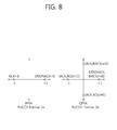
- FIG. 8 illustrates an example of constellation mapping of ACK/NACK in the PUCCH format 2a/2ba in the normal CP.
- the NACK (NACK and NACK in the case of transmitting two downlink codewords) is mapped to +1.
- DTX discontinuous transmission
- the 1 or 2-bit ACK/NACK is joint-coded with the CQI.
- FIG. 9 illustrates an example of joint coding of ACK/NACK and a CQI in an extended CP.
- the maximum bit number of information bits supported by an RM code may be 13.
- CQI information bits K cqi may be 11 bits and ACK/NACK information bits K ACK/NACK may be 2 bits.
- the CQI information bits and the ACK/NACK information bits are concatenated to generate a bit stream and thereafter, channel-coded by the RM code.
- it is expressed that the CQI information bits and the ACK/NACK information bits are joint-coded. That is, the CQI information bits and the ACK/NACK information bits are joint-coded to become 20 coded bits.
- a 20-bit codeword generated through such a process is transmitted in the PUCCH format 2 having the channel structure (different from FIG. 6 in that one RS symbol is used per slot in the case of the extended CP) described in FIG. 6 .
- the ACK/NACK and the SR are multiplexed to be simultaneously transmitted through the PUCCH format 1a/1b.
- FIG. 10 illustrates a method in which ACK/NACK and an SR are multiplexed.
- the user equipment transmits the ACK/NACK in an allocated SR resource and in this case, the ACK/NACK means a positive SR.
- the base station may know that the user equipment requests scheduling. Further, the user equipment may transmit the ACK/NACK in an allocated ACK/NACK resource and the ACK/NACK means a negative SR. That is, the base station may identify whether the SR is the positive SR or the negative SR as well as the ACK/NACK through which resource the ACK/NACK being transmitted in the subframe in which the ACK/NACK and the SR are simultaneously transmitted.
- FIG. 11 illustrates constellation mapping when the ACK/NACK and the SR are simultaneously transmitted.
- the DTX/NACK and the positive SR are mapped to +1 of a constellation map and the ACK is mapped to -1.
- the constellation map may show a phase of a signal.
- the user equipment may feed back to the base station a plurality of ACKs/NACKs for a plurality of PDSCHs.
- the reason is that the user equipment may receive the plurality of PDSCHs in a plurality of subframes and transmit the ACKs/NACKs for the plurality of PDSCH in one subframe.
- two types of ACK/NACK transmitting methods are provided.
- the first method is ACK/NACK bundling.
- ACK/NACK bundling ACK/NACK bits for a plurality of data units are coupled through a logical AND operation. For example, when the user equipment successfully decodes all of the plurality of data units, the user equipment transmits only one ACK bit. On the contrary, when the user equipment fails to decode or detect even any one of the plurality of data units, the user equipment transmits the NACK bit or transmit no NACK bit.
- Bundling includes spatial bundling, bundling in the time domain, and bundling in the frequency domain, and the like.
- the spatial bundling is a technique that compresses an A/N for each codeword at the time of receiving a plurality of codewords in one PDSCH.
- the bundling in the time domain is a technique that compresses A/N for data units received in different subframes.
- the bundling in the frequency domain is a technique that compresses A/N for data units received in different cells (that is, CCs).
- the second method is ACK/NACK multiplexing.
- contents or meanings of the ACKs/NACKs for the plurality of data units may be identified by combinations of PUCCH resources and QPSK modulated symbols used for actual ACK/NACK transmission. This is also called channel selection.
- the channel selection may be called PUCCH 1a/1b channel selection according to the used PUCCH.
- the ACK/NACK may be identified in a transmission node (for example, the base station) that transmits the data unit as shown in a table given below.
- HARQ-ACK(i) indicates an ACK/NACK result data unit i.
- two data units of data unit 0 and data unit 1 may be provided.
- the DTX means that the data unit for the corresponding HARQ-ACK(i) is not transmitted.
- the DTX means that the receiver (for example, the user equipment) is not capable of detecting the data unit for the HARQ-ACK(i).
- n (1) PUCCH,X indicates the PUCCH resource used for the actual transmission of the ACK/NACK and maximum two PUCCH resources are provided. That is, two PUCCH resources are n (1) PUCCH,0 and n (1) PUCCH,1 .
- b(0) and b(1) represent 2 bits transferred by a selected PUCCH resource. A modulated symbol transmitted through the PUCCH resource is determined according to b(0) and b(1).
- the receiver needs to transmit two bits (b(0), b(1)) as (1,1) by using the PUCCH resource n (1) PUCCH,1 .
- the receiver receives two data units to fail to decode a first data unit and succeed in decoding a second data unit. In this case, the receiver needs to transmit (0,0) by using n (1) PUCCH,1 .
- the ACKs/NACKs for the plurality of data units may be transmitted by using a single PUCCH resource by a method for linking the content (or meaning) of the ACK/NACK with a combination of a PUCCH resource and a content of an actual bit transmitted in the corresponding PUCCH resource.
- the NACK and the DTX is displayed as a couple such as the NACK/DTX.
- the reason is that it is short to cover all ACK/NACK combinations by distinguishing the NACK and the DTX by only a combination of the PUCCH resource and the QPSK symbol.
- the total number of PDSCHs as targets transmitted by the user equipment is important.
- the user equipment is not capable of receiving some PDCCHs among a plurality of PDCCHs to schedule a plurality of PDSCHs, an error occurs in the total number of the PDSCHs as the targets of the ACK/NACK, and as a result, a wrong ACK/NACK may be transmitted.
- a downlink assignment index (DAI) is transmitted with being included in the PDCCH in the TDD system.
- the DAI indicates a counting value by counting the number of the PDCCHs to schedule the PDSCH.
- Table 3 given below shows one example of a (20, A) RM code used for channel coding of the PUCCH format 2.
- A may represent the bit number (that is, K cqi + K ACK/NACK ) of the bit stream in which the CQI information bits and the ACK/NACK information bits are concatenated.
- the bit stream may be used as an input of a channel coding block using the (20, A) RM code.
- a bit stream channel-coded by the RM code, b 0 ,b 1 ,b 2 ,...,b B-1 may be generated as shown in Equation 1 given below.
- Channel-coded bits are mapped to the code-time-frequency resource.
- FIG. 12 illustrates an example in which channel-coded bits are mapped to a code-time-frequency resource.
- first 10 bits and last 10 bits among 20 bits which are channel-coded are mapped to different code-time-frequency resources and in particular, first 10 bits and last 10 bits are largely separated and transmitted in in the frequency domain for frequency diversity.
- a CSI of maximum 13 bits is RM-coded through the (20, A) RM code of Table 3.
- a CQI of maximum 11 bits is RM-coded through a (32, A) RM code of Table 4 given below and truncated or circularly repeated in order to match code rate to be transmitted in the PUSCH.
- PUCCH format 3 is introduced in order to transmit a UCI (the ACK/NACK and the SR) of maximum 21 bits (represent the bit number before channel coding as information bits and maximum 22 bits when the SR is included).
- the PUCCH format 3 performs block spreading based transmission. That is, a modulated symbol sequence that modulates a multi-bit ACK/NACK by using a block spreading code is spread and thereafter, transmitted in the time domain.
- FIG. 13 exemplifies a channel structure of PUCCH format 3.
- the block spreading code is applied to a modulated symbol sequence ⁇ d1, d2, ... ⁇ to be spread in the time domain.
- the block spreading code may be an orthogonal cover code (OCC).
- OOCC orthogonal cover code
- the modulated symbol sequence may be a sequence of the modulated symbols in which the ACK/NACK information bits which are multiple bits are channel-coded (using the RM code, a TBCC, a punctured RM code, and the like) to generate ACK/NACK coded bits and the ACK/NACK coded bits are modulated (for example, QPSK-modulated).
- the sequence of the modulated symbols is mapped to data symbols of the slot through fast Fourier transform (FFT) and inverse fast Fourier transform (IFFT) and thereafter, transmitted.
- FFT fast Fourier transform
- IFFT inverse fast Fourier transform
- FIG. 13 exemplifies a case in which two RS symbols exist in one slot, but three RS symbols may exist and in this case, a block spreading code having a length of 4 may be used.
- FIG. 14 exemplifies a dual RM coding process.
- a bit stream (information bits) is more than 11 bits
- a bit stream (referred to as a segment) segmented through segmentation is generated.
- each of segment 1 and segment 2 becomes 11 bits or less.
- the segments 1 and 2 are interleaved or concatenated through the (32, A) RM code. Thereafter, the UCI bit stream is truncated or circularly repeated in order to match the coded bit number of the PUCCH format 3.
- a modulation and coding scheme (MCS) and transmission power are controlled according to a given channel by using link adaptation in order to maximally use a channel capacity given in the wireless communication system.
- MCS modulation and coding scheme
- Channel information representing a status of a channel is referred to as the channel status information and the channel status information includes a precoding matrix index (PMI), a rank indicator (RI), a channel quality indicator (CQI), and the like.
- PMI precoding matrix index
- RI rank indicator
- CQI channel quality indicator
- the downlink transmission mode may be divided into 9 modes to be described below.
- MMSFN multicast-broadcast single frequency network
- the CSI may be transmitted through the PUCCH periodically according to a cycle determined in the higher layer.
- the user equipment may be semistatically by a higher layer signal so as to periodically feed back a differential CSI (CQI, PMI, RI) through the PUCCH.
- CQI, PMI, RI differential CSI
- the user equipment transmits the corresponding CSI according to modes defined as shown in a table given below.
- Transmission mode PUCCH CSI reporting modes Transmission mode 1 Modes 1-0, 2-0 Transmission mode 2 Modes 1-0, 2-0 Transmission mode 3 Modes 1-0, 2-0 Transmission mode 4 Modes 1-1, 2-1 Transmission mode 5 Modes 1-1, 2-1 Transmission mode 6 Modes 1-1, 2-1 Transmission mode 7 Modes 1-0, 2-0 Transmission mode 8
- PMI/RI reporting is set for modes 1-1 and 2-1 user equipments
- PMI/RI reporting is not set for modes 1-0 and 2-0 user equipments
- Transmission mode 9 When PMI/RI reporting is set for the modes 1-1 and 2-1 user equipments and the number of CSI-RS ports is larger than 1.
- PMI/RI reporting is not set for the modes 1-0 and 2-0 user equipments or the number of CSI-RS ports is 1
- a collision of the CSI report represents a case in which a subframe configured to transmit a first CSI and a subframe configured to transmit a second CSI are the same as each other.
- the collision of the CSI report occurs, the first CSI and the second CSI are simultaneously transmitted or transmission of a CSI having a low priority is abandoned (this will be referred to as drop) and a CSI having a high priority may be transmitted according to priorities of the first CSI and the second CSI.
- the CSI report through the PUCCH may include various report types according to a transmission combination of the CQI, the PMI, and the RI and a cycle and an offset value divided according to each report type (hereinafter, abbreviated as a type) are supported.
- N pd which is a subframe-unit cycle and an offset N offset,CQI are determined based on a parameter 'cqi-pmi-ConfigIndex' (I CQI/PMI ) for CQI/PMI reporting.
- period M RI and a relative offset N offset,RI are determined based on a parameter 'ri-ConfigIndex' (I RI ) for RI reporting.
- 'cqi-pmi-ConfigIndex' and 'ri-ConfigIndex' are set by the higher layer signal such as the RRC message.
- the relative offset N offset,RI for the RI has a value in a set ⁇ 0, -1, ... , -(N pd -1) ⁇ .
- a subframe in which the user equipment reports the CSI is referred to as a CSI subframe and a CSI subframe set constituted by a plurality of CSI subframes may be configured for the user equipment. If reporting is configured in two or more CSI subframe sets for the user equipment, 'cqi-pmi-ConfigIndex' and 'ri-ConfigIndex' corresponding to the respective CSI subframe sets are given.
- 'cqi-pmi-ConfigIndex' and 'ri-ConfigIndex' are for a first CSI subframe set and 'cqi-pmi-ConfigIndex2' and 'ri-ConfigIndex2' are for a second CSI subframe set.
- the CSI report which is the CSI type 1, 1a, 2, 2a, 2b, 2c, or 4 has a low priority and is dropped.
- the user equipment When two or more serving cells are configured for the user equipment, the user equipment performs only CSI reporting for only one serving cell in a given subframe.
- the CSI report which is the CSI type 3, 5, 6, or 2a of a first cell and the CSI report which is the CSI type 1, 1a, 2, 2a, 2b, 2c, or 4 of a second cell may collide with each other in the given subframe.
- the CSI report which is the CSI type 1, 1 a, 2, 2a, 2b, 2c, or 4 has the low priority and is dropped.
- a CSI report which is CSI type 2, 2b, 2c, or 4 of the first cell and a CSI report which is CSI type 1 or 1a of the second cell may collide with each other in the given subframe.
- the CSI report which is the CSI type 1 or 1a has the low priority and is dropped.
- the first cell and the second cell are different cells.
- CSI type CSI reports having the same priority in different serving cells may collide with each other in the given subframe.
- a CSI of a serving cell having the lowest serving cell index (ServCellIndex) is reported and CSIs of all other serving cells are dropped.
- a sounding reference signal is a reference signal not associated with PUSCH/PUCCH transmission and the SRS may be transmitted in the uplink.
- the transmission of the SRS includes a Type0 scheme and a Type1 scheme.
- the SRS is semistatically transmitted at the corresponding cycle according to a predetermined cycle.
- a triggering signal is included in a downlink control signal (downlink control information (DCI)).
- DCI downlink control information
- an SRS transmittable subframe is cell-specifically configured and the user equipment is capable of transmitting the SRS in only the corresponding subframe.
- the periodic CQI and the A/N are simultaneously transmitted by using the PUCCH format 2a/2b.
- the A/N is multiplexed by modulating a phase of a second reference signal symbol of the PUCCH format 2.
- a plurality of A/N for the plurality of PDSCHs (for example, PDSCHs received in a plurality of cells) needs to be transmitted. That is, in the LTE-A, since information amount of the A/N increases, a multiplexing method of the A/N and the CQI through a phase modulation scheme of a reference signal symbol in the related art may not be appropriate.
- the periodic CSI, A/N, SR, and the like are configured to be simultaneously transmitted through the same uplink control channel, disclosed are by what scheme the periodic CSI, A/N, SR, and the like are to be multiplexed and a method for selecting a control channel resource depending on UCI configuration.
- the UCI is a term that generically names the periodic CSI, A/N, SR, and the like.
- Such a method considers an operation which is strong to ambiguity in RRC reestablishment to configure simultaneous transmission of the A/N and the CSI or cancel the simultaneous transmission for the user equipment.
- the CSI may be limited to the periodic CSI.
- the PUCCH format 3 is exemplified as an uplink channel in which control information such as the A/N and the CSI is multiplexed and transmitted, but the uplink channel is not limited thereto.
- the present invention may be applied to even a new PUCCH format or PUSCH transmission acquired by modifying a coding chain, RE mapping, and the like of the PUCCH format 3.
- the user equipment may be configured to multiplexing and simultaneously transmit A/N for a plurality of cells (a plurality of DL CCs) and periodic CSIs for one or a plurality of cells (that is, one or a plurality of DL CCs).
- a plurality of DL CCs a plurality of DL CCs
- periodic CSIs for one or a plurality of cells
- the user equipment may select a transmission resource of the control channel according to a combination of UCIs to be transmitted.
- a DL subframe (e.g., defined in table 10.1.3.1-1 of subframe n-k, k ⁇ K, K is 3GPP TS 36.213, V10, Evolved Universal Terrestrial Radio Access(E-UTRA); physical layer procedures(Release 10) and a set constituted by M elements, that is, ⁇ k 0 , k 1 , ..., k M-1 ⁇ ) corresponding to the UL subframe (e.g., subframe n) to transmit the A/N, i) when one PDSCH scheduled without the PDCCH exists only in the PCC and there is no PDCCH requiring the A/N response, ii) when one PDSCH scheduled through the PDCCH exists only in the PCC and the DAI of the corresponding PDCCH is 1, or iii) when one PDCCH (e.g., the downlink SPS release PDCCH, hereinafter, the same as above) having the DAI of 1, which requires the A/N response exists and there
- a first HARQ-ACK corresponds to a PDSCH transmitted without the PDCCH
- a third HARQ-ACK corresponds to a second codeword of the PDSCH scheduled through the PDCCH having the DAI of 1.
- the PUCCH format 1a/1b or PUCCH format 1a/1b channel selection may be defined to be applied when the ARI for selecting the resource of the PUCCH format 3 may not be received from the PDCCH.
- the conditions of i) to iv) may be referred to as the single A/N (sA/N) for easy description.
- an exceptional method may be applied unlike the conditions i) to iii) (even in the case of the collisions of the SR and the CSI).
- An A/N transmitted in cases other than i) to iv) may be referred to as the multiple ACK/NACK (mA/N).
- the transmitted A/N may be referred to as the mA/N.
- the user equipment may transmit the A/N by using the PUCCH format 3.
- the implicit PUCCH resource corresponding to the CCE occupied by the PDCCH exists as described (some of ii), iii), and iv)
- the implicit resource is used and when the implicit PUCCH resource does not exist (some of i), v), and iv))
- one resource indicated by the ARI included in the PDCCH is selected and used from four explicit PUCCH resources allocated through the RRC.
- the CSI may be transmitted in the PUCCH format 2.
- the PUCCH format 3 may be used.
- the PUCCH format 3 may be separately allocated.
- the A/N transmission is required in the UL subframe (e.g., subframe n) to transmit the CSI for the DL CC, and in in a DL subframe (e.g., defined in table 10.1.3.1-1 of subframe n-k, k ⁇ K, K is 3GPP TS 36.213, V10, Evolved Universal Terrestrial Radio Access(E-UTRA); physical layer procedures(Release 10) and a set constituted by M elements, that is, ⁇ k 0 , k 1 , ..., k M-1 ⁇ ) corresponding to the UL subframe (e.g., subframe n) to transmit the A/N, i) when the PDSCH or the PDCCH requiring the A/N response is received only in the PCC, the CSI and the A/N may be multiplexed and transmitted in the PUCCH format 2b.
- the A/N for the plurality of DL subframes of the PCC may be in a bundled (method
- the CSI and the A/N may be multiplexed and transmitted in the PUCCH format 3.
- the A/N may be bundled for each DL CC (method 2).
- the CSI may be a CSI for one or the plurality of DL CCs.
- the CSI for the plurality of DL CCs is permitted to be transmitted, in a subframe in which the plurality of CSIs collide with each other, only the CSI for one DL CC is selected and residual CSIs are dropped in the case of i) to apply the PUCCH formats 2 and 3 series in the method 1.
- the method in which the PUCCH format 3 series in the method 1 is applied may be used for the plurality of CSIs and the method 2 may be used in the case of ii).
- a method may also be considered, in which in the subframe in which the single CSI is generated, the PUCCH format 2 series is used and in the subframe in which multiple CSIs are generated, the PUCCH format 3 series is used to multiplex the A/N and the CSI.
- the A/N for each DL subframe of each DL CC is spatially bundled (time-domain bundling / frequency-domain bundling is also available, and temporal bundling, the ACK counter, and the contiguous ACK counter for the entirety of the PCC and the SCC may be applied) and transmitted in the PUCCH format 1a/1b allocated by the RRC message for the positive SR and in the case where the SR is the negative SR, the same transmission method as when only the A/N is transmitted is used.
- the following method may be applied in the SR subframe.
- the SR to be transmitted in the SR subframe is the positive SR
- the CSI is dropped, and the SR and/or the A/N is transmitted to the PUCCH format 1/1a/1b allocated to the RRC for the positive SR.
- the SR bit and the CSI in the SR subframe is multiplexed (for example, joint coding) and transmitted to the PUCCH format 2 used for the CSI transmission.
- a sum pf the SR bit and the CSI exceeds a predetermined bit number (for example, a maximum bit number to be transmitted by the PUCCH format 2/2a/2b, 11 bits or 13 bits)
- a predetermined bit number for example, a maximum bit number to be transmitted by the PUCCH format 2/2a/2b, 11 bits or 13 bits
- the CSI is dropped, and only the A/N and the SR are transmitted to the PUCCH format 2/2a/2b (if there is the A/N), or the same method as the 1) method may be used.
- the SR in the case where the ARI may not be received from the PDCCH, when a PUCCH format 3 predefined for transmission of a plurality of CSIs is used, the following method may be applied in the SR subframe.
- the CSI is dropped, and the SR and/or the A/N is transmitted to the PUCCH format 1/1a/1b allocated to the RRC for the positive SR.
- the SR bit and the CSI in the SR subframe is multiplexed and transmitted to the PUCCH format 3 used for the CSI transmission.
- a sum pf the SR bit and the CSI exceeds a predetermined bit number (for example, a maximum bit number to be transmitted by the PUCCH format 3, 22 bits)
- some CSIs are dropped, and the A/N and the SR, and a single CSI are transmitted to the PUCCH format 3 (if there is the A/N), or the same method as the 1) method may be used.
- the spatial bundling may mean that the A/N for each codeword is compressed through a logic AND operation in the case where two codewords may be transmitted from one PDSCH. In the case of transmitting only one codeword or the PDCCH requiring one A/N, the spatial bundling for the A/N is not necessarily applied.
- the PUCCH format for multiplexing the A/N (and/or the SR bit) and the CSI (hereinafter, for convenience, referred to as a PUCCH format AC, and for example, the PUCCH format 3 may be the PUCCH format AC) is used, for flexibility of the resource selection, after a plurality (four) of resource sets are semi-statically allocated to a user equipment as the RRC, one resource of the allocated resource sets through the ARI (A/N resource indicator or PUCCH Resource Value for HARQ-ACK Resource for PUCCH, 2 bits) of the PDCCH may be dynamically indicated.
- the base station uses a TPC field of a predetermined PDCCH as the ARI, and this will be described as follows in more detail.
- the user equipment may receive the PUCCH format 3 used for the A/N transmission for the multi cells, or receive the PUCCH format 1a/1b channel selection use for the A/N transmission for the multi cells.
- TDD in the case of receiving the use of the PUCCH format 1a/1b channel selection for A/N transmission for multi cells: A different method from the aforementioned method may be applied. That is, in the case where the periodic CSI for the DL CC is set to be transmitted to the UL subframe (subframe n) in which the A/N of the PDSCH transmitted to the SCC is transmitted, the TPC field of the PDCCH, which is positioned in the DL subframe n-k (herein, k ⁇ K, K is a set defined in Table 10.1.3.1-1 of 3GPP TS 36.213.
- V10 Evolved Universal Terrestrial Radio Access (E-UTRA) and configured by M elements, that is, ⁇ k 0 , k 1 , ..., k M-1 ⁇ )
- E-UTRA Evolved Universal Terrestrial Radio Access
- M elements that is, ⁇ k 0 , k 1 , ..., k M-1 ⁇
- the ARI of the PDCCH which is positioned in the DL subframe n-k corresponding to the UL subframe n (that is, is not the subframe of the periodic CSI transmission cycle) requiring only the A/N transmission, indicates the selection of the PUCCH format 1a/1b resource for the channel selection, while the ARI of the PDCCH, which is positioned in the DL subframe n-k corresponding to the UL subframe n in which simultaneous transmission of the A/N and the CSI is required, indicates the resource of the PUCCH format AC (for example, the PUCCH format 3) for the multiplexing transmission of the A/N and the CSI.
- the PUCCH format AC for example, the PUCCH format 3
- the ARI does not exist in the PDCCH which is positioned in the DL subframe n-k corresponding to the UL subframe n in which only the A/N transmission is required, but the ARI indicating the resource of the PUCCH format AC for the simultaneous transmission of the A/N and the CSI exists in the PDCCH, which is positioned in the DL subframe n-k corresponding to the UL subframe n in which simultaneous transmission of the A/N and the CSI is required.
- the power control may use the PUSCH PC for data transmission.
- the TPC of the PDCCH scheduling (or downlink SPS releasing) the PDSCH of all cells may be used as the ARI.
- the ARI may directly indicate different kinds of PUCCH formats used as the PUCCH format for the A/N transmission.
- the ARI indicates a resource index of the same PUCCH format, and may select whether to use any PUCCH format among the formats defined as the predetermined RRC such as the PUCCH format 1a/1b, the PUCCH format 2, the PUCCH format 3, and the PUCCH format AC.
- the simultaneous transmission in the same subframe of the PUCCH format 2/2a/2b for the SRS and CSI transmission is not permitted, and a method in which one of two is dropped and only one is transmitted according to the condition is applied.
- the reason is that a shortened format for avoiding the collision with the transmission of the SRS may not be made, because in the case of the PUCCH format 2/2a/2b, unlike the PUCCH format 1 or 3, an orthogonal cover is applied to the SC-FDMA symbol, the repetitively coded bits are not transmitted, and different coded bits are loaded and transmitted in each SC-FDMA symbol.
- the method is applied to all of the cases where the HARQ-ACK transmission is included or not included in the PUCCH format 3 together with the CSI.
- the shortened PUCCH format 3 may be always used.
- the PUCCH format 3 for the A/N transmission is not implemented in a user equipment having capability for aggregating only two or less FDDs. In a user equipment having capability for aggregating only one or less TDD, the PUCCH format 3 for the A/N transmission is not implemented.
- the use of a PUCCH format x (x is for example, 3, 3a, 4...) for simultaneous transmission may be applied as follows according to capability of the user equipment and/or a setting of the PUCCH format x for the A/N transmission.
- the PUCCH format 1b channel selection is set for feedback of only the A/N for the plurality of cells (that is, using the PUCCH format 1b channel selection method during the A/N transmission in the case where the CSI subframe is not, and operations of a case where the A/N (mA/N and the CSI for the plurality of cells are set to be transmitted together may be divided as illustrated in the following Table.
- mA/N+sCSI TRUE PUCCH format 3 available UE PUCCH format 3 available UE UCI collision mA/N, sCSI mA/N, sCSI In the case where PUCCH format 3 is set for A/N feedback Multiplexing in PUCCH format 3 N/A In the case where channel selection is set for A/N feedback Multiplexing in PUCCH format 3 Multiplexing in PUCCH format 2
- the PUCCH format 1a/1b channel selection As the A/N transmission method, the "setting the PUCCH format 1a/1b channel selection" and the “setting the simultaneous transmission through the PUCCH format 3 by multiplexing the A/N for the multiple cells and one DL CC or a periodic CSI for the plurality of DL CCs" may not be simultaneously permitted.
- the “setting the simultaneous transmission through the PUCCH format 3 by multiplexing the A/N for the multiple cells and one DL CC or a periodic CSI for the plurality of DL CCs” may be permitted.
- the bit number of A/Ns is maximum 10 bits.
- the bit number of A/Ns is increased in proportional to M. Accordingly, in the case where the simultaneous transmission of the A/N and the CSI is set and the A/N and the CSI are transmitted to the PUCCH format 3, in 22 bits which may be maximally supported by the current PUCCH format 3, the bit number occupied by the A/N (the SR bit may be included) may exceed 11 bits.
- the application of the spatial bundling to the A/N may be set.
- the bundling setting may be used even in the case where the simultaneous transmission of the A/N and the CSI is set. This is because available transmittable A/N bits decreased due to the multiplexing with the CSI may be decreased.
- the bundling may be applied during the multiplexing of the multiple A/N and the CSI in the CSI subframe, and in the case of the subframe to which only the A/N is transmitted, the bundling may not be applied.
- the sum of the A/N and the CSI is possible because an A/N which is not bundled is also possible to transmit.
- the application of the bundling during only the A/N transmission may be determined according to a reference value based on the bit number of CSIs. In the case where the A/N bit number before bundling is larger than (or the same as) the reference value, the bundling is applied, and in the case where the A/N bit number before bundling is smaller than (or the same as) the reference value, the bundling is not applied.
- FIG. 15 illustrates an example of determining a reference value regarding whether bundling is applied at the time of transmitting only A/N.
- a maximum value (that is, a maximum value in time/frequency axes) of the CSI bit number to be transmitted to one subframe in each CSI report mode which is set to the DL cells (DL CCs) which are set to the user equipment may be a reference value. That is, when Max CSI0, Max CSI1, and Max CSI 2 are maximum values of the CSI bit number which may be transmitted from one subframe in the CSI report mode set in each CC, the maximum value among them may be the reference value.
- the implementation may be easily performed by using one value determined when an initial CSI report mode is set without comparison of priority or calculating the maximum value of the CSI number in each subframe. As a simpler method, it may be considered that the maximum CSI bit number (11 bits) transmitted from one subframe is fixed and transmitted in all the CSI report modes.
- periodic CSI transmission is configured to be independently set for each cell. Meanwhile, some of SCells set to the user equipment may be activated or deactivated. In the case of the deactivated cell, since the data transmission is not performed, the CSI report for the corresponding cell is not required. Accordingly, in an existing LTE-A Rel-10, the "CSI (transmission) subframe" which is a subframe in which the periodic CSI is transmitted to the uplink control channel may be defined as a union of the periodic CSI transmission subframes in the activated cell.
- the simultaneous transmission of the A/N (particularly, mA/N) and the CSI may be set, and in this case, when the A/N (particularly, mA/N) and the CSI are transmitted to the PUCCH format 3, in order to prevent ambiguity of a channel coding scheme due to error occurrence for activation/deactivation of the SCell between the base station and the user equipment, even though only a content for the activated cell in an actual content of the CSI is selected and transmitted, the CSI field needs to be set based on the set cell. Accordingly, in this case, the CSI (transmission) subframe may be newly defined as follows.
- the CSI report for the activated cell is selected and transmitted in the union of the periodic CSI transmission moment (subframe) in the set cell, herein, the CSI field, and in the case where there is no CSI report of the activated cell corresponding to the corresponding moment, the CSI report may not be transmitted to the reserved CSI field.
- a PUCCH format which is different from the A/N-only subframe (subframe which is a complementary set of the CSI subframe) is used, or the operation may vary. For example, changes in a transmission format of the A/N bit (the channel selection is changed into the PUCCH format 3), an operation and a format during the positive SR (the PUCCH format 1 is changed into the PUCCH format 3), and a detection operation of the ARI of the PDCCH of the DL subframe corresponding to the corresponding UL subframe are possible.
- simultaneous transmission of a single ACK/NACK (sA/N) and the CSI may be set.
- the setting may be performed by a parameter of 'simultaneousAckNackAndCQI' included in the RRC message.
- simultaneous transmission of an ACK/NACK for a plurality of cells, that is, a multiple ACK/NACK (mA/N) and the CSI may be set.
- the operation is a setting which is not included in the existing system, and in the present invention, an addition of a new parameter for the simultaneous transmission setting of the mA/N and the CSI is proposed.
- the new parameter may be included in the RRC message applied to the new system, and the title of the new parameter is called 'simultaneousAckNackAndCQI-Format3-R11'. That is, the simultaneous transmission setting of the mA/N and the CSI may be performed through the new parameter. Since the 'simultaneousAckNackAndCQI-Format3' is included in the LTE-A Rel-11, the 'simultaneousAckNackAndCQI-Format3-r11' is represented as the 'simultaneousAckNackAndCQI-r11'.
- the existing 'simultaneousAckNackAndCQI' has a value of true or false, as a parameter included in the RRC message (that is, the CQI-ReportConfig information element). In the case where the parameter is True, the simultaneous transmission of the ACK/NACK and the CQI is permitted.
- the 'simultaneousAckNackAndCQI-Format3' also has a value of true or false, as a parameter included in the RRC message.
- the parameter may indicate whether the user equipment multiplexes the ACK/NACK and the periodic CQI to transmit the ACK/NACK and the periodic CQI to the specific PUCCH format, for example, the PUCCH format 3.
- FIG. 16 illustrates an operation of a terminal depending on setting P1 and P2.
- P1 is 'simultaneousAckNackAndCQI'
- P2 is 'simultaneousAckNackAndCQI-Format3-R11'.
- the user equipment transmits a single A/N 161 through the PUCCH format 1a/1b if only the single A/N exists in the corresponding subframe. If only the CSI exists, a CSI 162 is transmitted through the PUCCH format 2, and when the CSI and the single A/N 163 exist, the CSI and the single A/N are simultaneously transmitted through the PUCCH format 2a/2b. In addition, in the case where a multiple A/N 164 and the CSI collide with each other, the CSI is dropped and the multiple A/N is transmitted through the PUCCH format 3.
- the PUCCH format 3 is transmitted from a resource indicated by the ARI (using the TPC field) of the PDCCH among four explicit resources set by the RRC message.
- the aforementioned four operations are supported, and the user equipment performs the operation according to occurrence of the A/N and the CSI in the subframe which transmits the UCI.
- the P2 parameter needs to be introduced. If the new parameter is not introduced and the simultaneous transmission of the multiple A/N and the CSI is set by the existing parameter P1, the malfunction of the user equipment may occur.
- the existing parameter P1 is transmitted from the base station which does not support the simultaneous transmission of the multiple A/N and the CSI
- the user equipment which supports the multiple A/N and the CSI uncertainty for whether the simultaneous transmission of the multiple A/N and the CSI is applied occurs. The reason of the uncertainty is that the user equipment transmits information on the operation supported by the user equipment to the network, while the network does not notify information on an operation supported by the base station to the user equipment.
- the operation of the user equipment may vary according to whether the P2 parameter is TRUE or FALSE. That is, in the case where the P2 parameter is TRUE, the multiple A/N and the CSI 165 are multiplexed to be transmitted through the PUCCH format 3.
- FIG. 17 illustrates an operation method of a terminal according to an embodiment of the present invention.
- the user equipment receives a first parameter indicating whether a (first set of) A/N and a CSI are simultaneously transmitted and a second parameter indicating whether a (second set of) A/N and a periodic CSI are multiplexed to be transmitted to the PUCCH format 3 (S10).
- the first set of A/N may be an A/N (A) when one PDSCH exists only in the PCC and is scheduled without the PDCCH (to the SPS), (B) when one PDSCH exists only in the PCC and is scheduled to the PDCCH, or (C) when one PDCCH exists only in the PCC and the PDCCH requires the A/N response (ex. PDCCH notifying the DL SPS release), and the second set of A/N may be other A/N sets.
- A when one PDSCH exists only in the PCC and is scheduled without the PDCCH (to the SPS)
- B when one PDSCH exists only in the PCC and is scheduled to the PDCCH
- C when one PDCCH exists only in the PCC and the PDCCH requires the A/N response (ex. PDCCH notifying the DL SPS release)
- the second set of A/N may be other A/N sets.
- the second parameter may be transmitted by the base station only in the case where the second set of ACK/NACK is set to be transmitted to the specific PUCCH format (for example, the PUCCH format 3).
- the first parameter may be 'simultaneousAckNackAndCQI'
- the second parameter may be 'simultaneousAckNackAndCQI-Format3-r11'.
- the higher layer signal may be the RRC message.
- the user equipment determines values of the first parameter and the second parameter (S20) to multiplex and transmit the A/N and the periodic CSI according to the values of the first parameter and the second parameter (S30).
- the first set of ACK/NACK or the second set of ACK/NACK is multiplexed with the CQI based on the first parameter and the second parameter to be transmitted through the first PUCCH format (the first set of ACK/NACK + periodic CQI) or the second PUCCH format (the second set of ACK/NACK + periodic CSI).
- the first PUCCH format may be the PUCCH format 2/2a/2b
- the second PUCCH format may be the PUCCH format 3.
- 'simultaneousAckNackAndCQI' is set as TRUE and the PUCCH format 1b channel selection is configured for the user equipment and the user equipment drops the CSI and transmits the HARQ-ACK (A/N) when receiving at least one PDSCH in subframe n - k (k ⁇ K, is the same as K described above) of the SCell.
- ⁇ 'simultaneousAckNackAndCQI' is set as TRUE and 'simultaneousAckNackAndCQI-Format3-r11' is set as FALSE ⁇ or ⁇ 'simultaneousAckNackAndCQI' is set as TRUE and 'simultaneousAckNackAndCQI-Format3-r11' is set as TRUE and the PUCCH resource is not determined by the ARI ⁇ ,
- the user equipment transmits the CSI and the A/N by using the PUCCH format 2/2a/2b.
- the SR if the SR exists) are not larger than 22 or
- the user equipment transmits the A/N, the SR (if the SR exists), and the CSI through the PUCCH format 3.
- the user equipment drops the CSI and transmits the A/N.
- the user equipment transmits the positive SR by using the PUCCH format 1.
- the user equipment is not configured in the PUCCH format 3, or
- the user equipment is configured in the PUCCH format 3 and 'simultaneousAckNackAndCQI-Format3-r11' is set as FALSE, or
- the user equipment is configured in the PUCCH format 3 and 'simultaneousAckNackAndCQI-Format3-r11' is set as TRUE and the PUCCH resource is not determined by the ARI,
- the user equipment multiplexes the A/N and the periodic CSI by using the PUCCH format 2/2a/2b.
- the user equipment is configured in the PUCCH format 3 and 'simultaneousAckNackAndCQI-Format3-r11' is set as TRUE and the PUCCH resource is determined by the ARI, and
- the SR if the SR exists) are not larger than 22 or
- the user equipment multiplexes the periodic CSI and the A/N to transmit the multiplexed periodic CSI and A/N through the PUCCH format 3.
- the user equipment drops the CSI.
- the HARQ-ACK and the CSI are multiplexed and transmitted in the PUCCH format 3 indicated by the ARI. That is, the HARQ-ACK and the CSI are multiplexed and transmitted in the PUCCH format 3 indicated by the ARI PUCCH format 3 is allocated instead of PUCCH format 2 for transmitting only CSI
- the configuration between the PUCCH format 3 and the PUCCH format 2 is changeable.
- the PUCCH format 3 When a fixed resource in which the PUCCH format 3 is RRC-configured is used to transmit only the CSI, only the CSI is transmitted or HARQ-ACK(w/o ARI) and the CSI are multiplexed to be transmitted in the PUCCH format 3.
- using the PUCCH format 3 instead of the PUCCH format 2/2a/2b may be determined depending on whether the PUCCH format 3 resource being allocated for transmitting only the CSI.
- CASE 1 A case in which the PUCCH format 3 is used to transmit only the A/N for the plurality of cells or for simultaneously the A/N and the CSIs for the plurality of cells is referred to as CASE 1.
- CASE 2 A case in which the PUCCH format 1b channel selection is used to transmit only the A/N for the plurality of cells and the PUCCH format 3 is used to simultaneously transmit the A/N and the CSIs for the plurality of cells is referred to as CASE 2.
- the PUCCH format 3 is used only in a CSI transmission subframe. Accordingly, consumption of the PUCCH format resource is decreased.
- the CSI transmission subframe may be configured with a time difference between the plurality of user equipments. Accordingly, the user equipment may more easily share the resource. Therefore, in the case of the PUCCH format 3 resource, only one resource may be allocated through the RRC and the resource may be continuously used.
- CASE 2 is distinguished from CASE 1 in which a plurality of resources (four resources) is allocated through the RRC and one resource indicated by the ARI included in the PDCCH, among the plurality of resources is used.
- the resource may be used even when the PUCCH format 3 is not the CSI subframe. Therefore, it is preferable that the plurality of user equipments share the PUCCH resource to be selectively indicated by the ARI.
- the RRC may be used to designate selection of the PUCCH format through which the CSI is to be transmitted. For example, when the ARI is received, the mA/N is transmitted by using the PUCCH format 3 and when the ARI is not received, the sA/N is transmitted by using the PUCCH format 2.
- the PUCCH format 3 may be used for feeding back only the A/N for the plurality of cells.
- a plurality of PUCCH format 3 resources is configured through the RRC message. Therefore, configuring the PUCCH format 3 resource for simultaneously transmitting the A/N for the plurality of cells and the CSI is not required.
- the PUCCH format 1 channel selection may be used for feeding back only the A/N for the plurality of cells.
- the PUCCH format 3 resource is not allocated. Therefore, when the A/N and the CSI for the plurality of cells are configured to be simultaneously transmitted, allocating the PUCCH format 3 resource is required.
- the PUCCH format 3 is configured by the feedback method of only the A/N for the plurality of cells at the time of configuring CASE 1, it is necessary to determine which one of the PUCCH format 3 resource allocation and PUCCH format 3 resource allocation configured at the time of simultaneously transmitting the A/N and the CSI.
- Values in both cases may be configured to be the same as each other, 2) a resource allocation index of CASE A may be continuously used and other resource allocation indexes may be disregarded, 3) a resource allocation index of CASE B may be continuously used and other resource allocation indexes may be disregarded, or 4) a resource allocation index of CASE A or B changed in recent years may be used.
- periodic CSIs for a plurality of downlink cells configured for the user equipment may not be simultaneously transmitted in one UL subframe and only one selected CSI is transmitted and residual CSIs are dropped.
- simultaneous transmission of multiple CSIs (that is, the plurality of CSIs for the plurality of cells) may be permitted.
- the simultaneous transmission of the multiple CSIs may be configured by an RRC parameter (for example, 'multiCellCQI-R12').
- RRC parameter for example, 'multiCellCQI-R12'.
- FIG. 18 illustrates a case in which the terminal transmits a UCI according to three RRC parameters.
- P1 is 'simultaneousAckNackAndCQI' and P2 is 'simultaneousAckNackAndCQI-Format3-R11'.
- P3 may be 'multiCellCQI-r12' that represents whether to simultaneously transmit the multiple CSIs. Operations represented by (0) to (5) in FIG. 18 have been described in FIG. 16 .
- (2.1) represents that the multiple CSIs are transmitted through the explicit PUCCH format 3 resource when only the multiple CSIs are generated in the case where P3 is set as TRUE.
- (3.1) represents that the multiple CSIs and the single A/N are transmitted through the explicit PUCCH format 3 resource when the P3 is set as TRUE and the multiple CSIs and the single A/N collide with each other.
- User equipment operated by Rel-11 may constitute as separate parameters simultaneousAckNackAndCQI-R11 and multiCellCQI-R12.
- (2.1) and (3.1) may be applied as they are or only when only the single CSI is generated, the operations (1) and (5) may be substituted with (2) and (3).
- simultaneousAckNackAndCQI may be set as TRUE (alternatively, disregarded).
- simultaneousAckNackAndCQI may be set as FALSE (alternatively, disregarded).
- multiCellCQI-R12 may be substituted with simultaneousAckNackAndCQI (override to the same RRC field).
- (2.1) may be applied as it is or only when only the single CSI is generated, the operations (1), (3), and (5) may be substituted with (2).
- simultaneousAckNackAndCQI may be set as TRUE (alternatively, disregarded).
- simultaneousAckNackAndCQI may be set as FALSE (alternatively, disregarded).
- multiCellCQI-R12 may be substituted with simultaneousAckNackAndCQI (override to the same RRC field).
- multiCellCQI-R12 and simultaneousAckNackAndCQI may be overridden with parameters or set as separate parameters and made to be correlated with each other (alternatively, disregarded) or set as independent parameters.
- multiCellCQI-R12 and simultaneousAckNackAndCQI are set as the independent parameters, multiCellCQI-R12 is applied to selection of (5)-TRUE and (4)-FALSE and simultaneousMultiCellCQI is applied to selection of (3)-TRUE and (0)-FALSE.
- the time-domain bundling includes application of the logic AND operation to the ACK that exists in the time domain, the ACK counter for transmitting the total number of ACKs, or the contiguous ACK counter for transmitting only the number of ACKs which are contiguous from the ACK corresponding to the first DAI value.
- Configuring the A/N and the CSI means that the multi-cell A/N and 'the periodic CSI for the single DL CC or the plurality of DL CCs' are configured to be multiplexed to be simultaneously transmitted in the PUCCH format 3.
- the multi-cell A/N (A/N for the plurality of DL CCs) means an A/N (alternatively, an A/N in the case of receiving from the PDCCH the ARI for selecting the PUCCH format 3 or the explicit PUCCH format 1a/1b) when the A/N for the SCell DL CC is included.
- Configuring the sA/N and the CSI means configuring the simultaneous transmission of the single A/N and the CSI of Rel-10 in which the multi-cell A/N and CSI are not permitted to be simultaneously transmitted.
- the single A/N means the A/N for the PCell DL CC (alternatively, an A/N when the ARI for selecting the PUCCH format 3 or the explicit PUCCH format 1a/1b is not received from the PDCCH).
- FIG. 19 is a block diagram illustrating a base station and a terminal in which the embodiment of the present invention is implemented.
- a base station 100 includes a processor 110, a memory 120, and a radio frequency (RF) unit 130.
- the processor 110 implements a function, a process, and/or a method which are proposed. Layers of a wireless interface protocol may be implemented by the processor 110.
- the processor 110 may notify a UCI transmitting method of a user equipment by transmitting a first parameter and a second parameter through a higher layer signal such as an RRC message.
- the memory 120 is connected with the processor 110 to store various pieces of information for driving the processor 110.
- the RF unit 130 is connected with the processor 110 to transport and/or receive the radio signal.
- a UE 200 includes a processor 210, a memory 220, and an RF unit 230.
- the processor 210 implements a function, a process, and/or a method which are proposed. Layers of a wireless interface protocol may be implemented by the processor 210.
- the processor 210 receives a first parameter and a second parameter through a higher layer signal and multiplexes an ACK/NACK and periodic CSI according to the values to transmit the multiplexed ACK/NACK and the periodic CSI through a specific PUCCH format.
- the memory 220 is connected with the processor 210 to store various pieces of information for driving the processor 210.
- the RF unit 230 is connected with the processor 210 to transport and/or receive the radio signal.
- the processors 110 and 210 may include an application-specific integrated circuit (ASIC), another chip set, a logic circuit and/or a data processing apparatus.
- the memories 120 and 220 may include a read-only memory (ROM), a random access memory (RAM), a flash memory, a memory card, a storage medium, and/or another storage device.
- the RF units 130 and 230 may include a baseband circuit for processing the radio signal.
- the aforementioned technique may be implemented by a module (a process, a function, and the like) that performs the aforementioned function.
- the module may be stored in the memories 120 and 220, and executed by the processors 110 and 210.
- the memories 120 and 220 may be provided inside or outside the processors 110 and 210 and connected with the processors 110 and 210 by various well-known means.
Abstract
Description
- The present invention relates to wireless communication, and more particularly, to a method and an apparatus for transmitting uplink control information in a wireless communication system.
- In a wideband wireless communication system, effective transmission and reception techniques and utilization measures have been proposed in order to maximize efficiency of limited radio resources. One of systems considered as a next-generation wireless communication system is an orthogonal frequency division multiplexing (OFDM) system that can attenuate an inter-symbol interference (ISI) effect with low complexity. In the OFDM, a data symbol input in series is converted into N parallel data symbols which are loaded on N separated subcarriers to be transmitted, respectively. The subcarriers maintain orthogonality in respect of a frequency. Respective orthogonal channels undergo independent frequency selective fading, and as a result, complexity in a receiver is decreased and an interval of transmitted symbols is increased to minimize inter-symbol interference.
- Orthogonal frequency division multiple access (hereinafter, referred to as OFDMA) represents a multiple access method that implements a multiple access by independently some of usable subcarriers to each user in a system using the OFDM as a modulation scheme. The OFDMA provides frequency resources such as the subcarriers to each user and the respective frequency resources are independently provided to a plurality of users not to be overlapped with each other, in general. Consequently, the frequency resources are exclusively allocated for each user. In the OFDMA system, frequency diversity for multiple users may be acquired through frequency selective scheduling and the subcarriers may be allocated in various patterns according to a permutation scheme for the subcarriers. In addition, efficiency of a spatial area may be increased by a space multiplexing technique using multiple antennas.
- Multiple-input multiple-output (MIMO) technology improves transmission and reception efficiency of data by using multiple transmitting antennas and multiple receiving antennas. A technique for implementing diversity in an MIMO system includes a space frequency block code (SFBC), a space time block code (STBC), cyclic delay diversity (CDD), frequency switched transmit diversity (FSTD), time switched transmit diversity (TSTD), precoding vector switching (PVS), spatial multiplexing (SM), and the like. An MIMO channel matrix depending on the number of receiving antennas and the number of transmitting antennas may be dissolved into a plurality of independent channels. The respective independent channels are called layers or streams. The number of layers represents a rank.
- Uplink control information (UCI) may be transmitted through a physical uplink control channel (PUCCH). The uplink control information may include various types of information including a scheduling request (SR), an acknowledgement/non-acknowledgement (ACK/NACK) signal, a channel quality indicator (CQI), a precoding matrix indicator (PMI), a rank indicator (RI), and the like. The PUCCH transports various types of control information according to a format.
- In recent years, a carrier aggregation system attracts attention. The carrier aggregation system means a system that configures a wideband by collecting one or more subcarriers having a smaller bandwidth than a target wideband when the wireless communication system supports the wideband.
- In the carrier aggregation system, a method for efficiently and reliably transmitting various types of uplink control information is required.
- The present invention provides a method and an apparatus for transmitting uplink control information in a wireless communication system.
- In one aspect, provided is a method for transmitting uplink control information (UCI) performed by user equipment in a wireless communication system. The method includes: receiving a first parameter for indicating whether to simultaneously transmit a first combination of an acknowledgment/no-acknowledgement (ACK/NACK) and a channel quality indicator (CQI) and a second parameter for indicating whether to multiplex a second combination of an ACK/NACK and the CQI and transmit the multiplexed second combination in a second physical uplink control channel (PUCCH) format; and multiplexing the first combination of the ACK/NACK or the second combination of the ACK/NACK with the CQI and transmitting the multiplexed ACK/NACK and CQI through a first PUCCH format or the second PUCCH format.
- In another aspect, provided is a user equipment. The user equipment includes: method includes: a radio frequency (RF) unit transmitting or receiving a radio signal; and a processor connected with the RF unit, wherein the processors receives a first parameter for indicating whether to simultaneously transmit a first combination of an acknowledgment/no-acknowledgement (ACK/NACK) and a channel quality indicator (CQI) and a second parameter for indicating whether to multiplex a second combination of an ACK/NACK and the CQI and transmit the multiplexed second combination in a second physical uplink control channel (PUCCH) format, and multiplexes the first combination of the ACK/NACK or the second combination of the ACK/NACK with the CQI and transmits the multiplexed ACK/NACK and CQI through a first PUCCH format or the second PUCCH format.
- When different types of uplink control information (UCI) needs to be transmitted in the same subframe, the uplink control information may be efficiently multiplexed and transmitted.
-
-
FIG. 1 illustrates a structure of a radio frame in 3GPP LTE. -
FIG. 2 illustrates one example of a resource grid for one downlink slot. -
FIG. 3 illustrates a structure of a downlink subframe. -
FIG. 4 illustrates a structure of an uplink subframe. -
FIG. 5 illustrates a comparative example of a single carrier system and a carrier aggregation system. -
FIG. 6 illustrates a channel structure of aPUCCH format 2/2a/2b for one slot in a normal CP. -
FIG. 7 illustrates a PUCCH format 1a/1b for one slot in the normal CP. -
FIG. 8 illustrates an example of constellation mapping of ACK/NACK in the PUCCHformat 2a/2ba in the normal CP. -
FIG. 9 illustrates an example of joint coding of ACK/NACK and a CQI in an extended CP. -
FIG. 10 illustrates a method in which ACK/NACK and an SR are multiplexed. -
FIG. 11 illustrates constellation mapping when the ACK/NACK and the SR are simultaneously transmitted. -
FIG. 12 illustrates an example in which channel-coded bits are mapped to a code-time-frequency resource. -
FIG. 13 exemplifies a channel structure ofPUCCH format 3. -
FIG. 14 exemplifies a dual RM coding process. -
FIG. 15 illustrates an example of determining a reference value regarding whether bundling is applied at the time of transmitting only A/N. -
FIG. 16 illustrates an operation of a terminal depending on setting P1 and P2. -
FIG. 17 illustrates an operation method of a terminal according to an embodiment of the present invention. -
FIG. 18 illustrates a case in which the terminal transmits a UCI according to three RRC parameters. -
FIG. 19 is a block diagram illustrating a base station and a terminal in which the embodiment of the present invention is implemented. - Technology described below may be used in various wireless communication systems including code division multiple access (CDMA), frequency division multiple access (FDMA), time division multiple access (TDMA), orthogonal frequency division multiple access (OFDMA), single carrier-FDMA (SC-FDMA), and the like. The CDMA may be implemented by radio technology universal terrestrial radio access (UTRA) or CDMA2000. The TDMA may be implemented by radio technology such as Global System for Mobile communications (GSM)/General Packet Radio Service(GPRS)/Enhanced Data Rates for GSM Evolution (EDGE). The OFDMA may be implemented as radio technology such as IEEE 802.11(Wi-Fi), IEEE 802.16(WiMAX), IEEE 802-20, E-UTRA(Evolved UTRA), and the like. IEEE 802.16m as the evolution of IEEE 802.16e provides backward compatibility with a system based on the IEEE 802.16e. The UTRA is a part of a universal mobile telecommunication system (UMTS). 3rd generation partnership project (3GPP) long term evolution (LTE) as a part of an evolved UMTS (E-UMTS) using evolved-UMTS terrestrial radio access (E-UTRA) adopts the OFDMA in a downlink and the SC-FDMA in an uplink. LTE-advanced (A) is an evolution of the 3GPP LTE. The LTE/LTE-A is primarily described for clear description, but the spirit of the present invention is not limited thereto.
- The wireless communication system includes at least one base station (BS). Each base station provides a communication service to a specific geographical region. User equipment (UE) may be fixed or movable and may be called other terms such as a mobile station (MS), a mobile terminal (MT), a user terminal (UT), a subscriber station (SS), a wireless device, a personal digital assistant (PDA), a wireless modem, a handheld device, and the like. The base station generally represents a fixed station that communicates with a terminal, and may be called different terms such as an evolved-NodeB (eNB), a base transceiver system (BTS), an access point, and the like.
- The user equipment generally belongs to one cell and the cell to which the terminal belongs is referred to as a serving cell. A base station that provides the communication service to the serving cell is referred to as a serving BS. The serving base station may provide one or a plurality of serving cells.
- The technology may be used in a downlink or an uplink. In general, the downlink means communication from the base station to the terminal and the uplink means communication from the terminal to the base station.
- Layers of a radio interface protocol between the terminal and the base station may be divided into a first layer (L1), a second layer (L2), and a third layer (L3) based on three lower layers of an open system interconnection (OSI) model which is widely known in a communication system.
- A physical layer as the first layer is connected with a medium access control (MAC) layer which is a higher layer through a transport channel and data moves between the MAC layer and the physical layer through the transport channel. In addition, data moves between different physical layers, that is, between physical layers at a transmitter and a receiver through a physical channel.
- A radio data link layer as the second layer is constituted by the MAC layer, an RLC layer, and a PDCP layer. The MAC layer as a layer that takes charge of mapping a logic channel and the transport channel selects an appropriate transport channel in order to transmit data transferred from the RLC layer and adds required control information to a header of an MAC protocol data unit (PDU).
- The RLC layer is positioned on a layer upper than the MAC layer to support reliable transmission of data. Further, the RLC layer segments and concatenates RLC service data units (SDUs) transferred from the higher layer in order to configure data having an appropriate size suitable for a radio interval. The RLC layer of a receiver supports a reassembling function of data in order to restore an original RLC SDU from the received RLC PDUs.
- The PDCP layer is used only in a packet exchange area and a header of an IP packet may be compressed and transmitted so as to increase transmission efficiency of packet data in a radio channel.
- The RRC layer as the third layer serves to control a lower layer and exchanges radio resource control information between the user equipment and a network. Various RRC statuses including an idle mode an RRC connected mode, and the like are defined according to a communication status of the user equipment and transition between the RRC statuses is possible as necessary. In the RRC layer, various procedures associated with radio resource management are defined, which include system information broadcasting, an RRC access management procedure, a multiple component carrier configuring procedure, a radio bearer controlling procedure, a security procedure, a measurement procedure, a mobility management procedure (handover), and the like.
- The wireless communication system may be any one of a multiple-input multiple-output (MIMO) system, a multiple-input single-output (MISO) system, a single-input single-output (SISO) system, and a single-input multiple-output (SIMO) system. The MIMO system uses a plurality of transmit antennas and a plurality of receive antennas. The MISO system uses a plurality of antennas and one receive antenna. The SISO system uses one antenna and one receive antenna. The SIMO system uses one transmit antenna and one receive antenna. Hereinafter, the transmit antenna means a physical or logical antenna used to transmit one signal or stream and the receive antenna means a physical or logical antenna used to receive one signal or stream.
-
FIG. 1 illustrates a structure of a radio frame in 3GPP LTE. - This may refer to
section 5 of 3rd Generation Partnership Project (3GPP) TS 36.211 V8.2.0 (2008-03) "Technical Specification Group Radio Access Network; Evolved Universal Terrestrial Radio Access (E-UTRA); Physical channels and modulation (Release 8)". Referring toFIG. 1 , the radio frame is constituted by 10 subframes and one subframe is constituted by 2 slots. Slots in the radio frame are numbered with slots numbers of #0 to #19. A time required to transmit one subframe is referred to as a transmission time interval (TTI). The TTI may be a scheduling unit for data transmission. For example, the length of one frame may be 10 ms, the length of one subframe may be 1 ms, and the length of one slot may be 0.5 ms. - One slot includes a plurality of orthogonal frequency division multiplexing (OFDM) symbols in a time domain and includes a plurality of subcarriers in a frequency domain. Since the 3GPP LTE uses the OFDMA in the downlink, the OFDM symbol is used to express one symbol period and may be called other name according to a multiple access scheme. For example, when SC-FDMA is used as an uplink multiple access scheme, the OFDM symbol may be called an SC-FDMA symbol. A resource block (RB) includes a plurality of contiguous subcarriers in one slot as a resource allocation unit. The structure of the radio frame is just one example. Accordingly, the number of subframes included in the radio frame, the number of slots included in the subframe, or the number of OFDM symbols included in the slot may be variously changed.
- The 3GPP LTE defines that one slot includes 7 OFDM symbols in a normal cyclic prefix (CP) and one slot includes 6 OFDM symbols in an extended CP.
- The wireless communication system may be generally divided into a frequency division duplex (FDD) scheme and a time division duplex (TDD) scheme. According to the FDD scheme, uplink transmission and downlink transmission are performed while occupying different frequency bands. According to the TDD scheme, the uplink transmission and the downlink transmission are performed at different timings while occupying the same frequency band. A channel response of the TDD scheme is substantially reciprocal. This means that a downlink channel response and an uplink channel response are almost the same as each other in a given frequency domain. Accordingly, in the wireless communication system based on the TDD, the downlink channel response may be acquired from the uplink channel response. In the TDD scheme, since an entire frequency band is time-divided into the uplink transmission and the downlink transmission, the downlink transmission by the base station and the uplink transmission by the terminal may not simultaneously be performed. In the TDD system in which the uplink transmission and the downlink transmission are divided by the unit of the subframe, the uplink transmission and the downlink transmission are performed in different subframes.
-
FIG. 2 illustrates one example of a resource grid for one downlink slot. - The downlink slot includes a plurality of OFDM symbols in the time domain and includes NRB resource blocks in the frequency domain. The number NRB of resource blocks included in the downlink slot is subordinate to a downlink bandwidth NDL set in a cell. For example, in an LTE system, NRB may be any one of 6 to 110. One resource block includes a plurality of subcarriers in the frequency domain. A structure of an uplink slot may also be the same as that of the downlink slot.
- Each element on the resource grid is called a resource element (RE). The resource element on the resource grid may be identified by a pair of indexes (k,l) in the slot. Herein, k (k = 0,..., NRB x 12-1) represents a subcarrier index in the frequency domain and l (l = 0,...,6) represents an OFDM symbol index in the time domain.
- Herein, it is exemplarily described that one resource block is constituted by 7 OFDM symbols in the time domain and 12 subcarriers in the frequency domain and thus includes 7 x 12 resource elements, but the number of the OFDM symbols and the number of the subcarriers in the resource block are not limited thereto. The number of the OFDM symbols and the number of the subcarriers may be variously changed depending on the length of a CP, frequency spacing, and the like. For example, in the case of a normal CP, the number of OFDM symbols is 7 and in the case of an extended CP, the number of OFDM symbols is 6. As the number of subcarriers in one OFDM symbol, one may be selected and used among 128, 256, 512, 1024, 1536, and 2048.
-
FIG. 3 illustrates a structure of a downlink subframe. - The downlink subframe includes two slots in the time domain and each slot includes seven OFDM symbols in the normal CP. Preceding maximum 3 OFDM symbols (maximum 4 OFDM symbols for a 1.4 Mhz bandwidth) of a first slot in the subframe are a control region to which control channels are allocated and residual OFDM symbols become a data region to which a physical downlink shared channel (PDSCH) is allocated.
- A PUCCH may transport resource allocation and a transmission format of a downlink-shared channel, resource allocation information of an uplink shared channel, paging information on a PCH, system information on the DL-SCH, resource allocation of a higher layer control message such as a random access response transmitted on the PDSCH, a set of transmission power control commands for individual UEs in a predetermined UE group, and activation of voice over Internet protocol (VoIP). A plurality of PDCCHs may be transmitted in the control region and the terminal may monitor the plurality of PDCCHs. The PDCCH is transmitted on aggregation of one or several contiguous control channel elements (CCEs). The CCE is a logical allocation unit used to provide to the PDCCH coding rate depending on a state of a radio channel. The CCEs correspond to a plurality of resource element groups. A format of the PDCCH and the bit number of an available PDCCH are determined according to a correlation of the number of CCEs and the coding rate provided by the CCEs.
- The base station determines the PDCCH format according to the downlink control information (DCI) to be sent to the terminal and affixes a cyclic redundancy check (CRC) to the control information. A unique identifier (radio network temporary identifier (RNTI)) is masked on the CRC according to an owner or a purpose of the PDCCH. In the case of a PDCCH for a specific terminal, a unique identifier of the terminal, for example, a cell (C)-RNTI may be masked on the CRC. Alternatively, in the case of a PDCCH for a paging message, a paging indication identifier, for example, a paging (P)-RNTI may be masked on the CRC. In the case of a PDCCH for a system information block (SIB), a system information (SI)-RNTI may be masked on the CRC. A random access (RA)-RNTI may be masked on the CRC in order to indicate the random access response which is a response to transmission of a random access preamble of the terminal.
-
FIG. 4 illustrates a structure of an uplink subframe. - The uplink subframe may be divided into a control region and a data region in the frequency domain. The physical uplink control channel (PUCCH) for transmitting the uplink control information is allocated to the control region. The physical uplink shared channel (PUSCH) for transmitting data is allocated to the data region.
- When indicated in a higher layer, the terminal may support simultaneous transmission of the PUSCH and the PUCCH.
- A PUCCH for one terminal is allocated to a resource block pair in the subframe. Resource blocks that belong to the resource block pair occupy different subcarriers in first and second slots, respectively. A frequency occupied by the resource block that belongs to the resource block pair allocated to the PUCCH is changed based on a slot boundary. This means that the RB pair allocated to the PUCCH is frequency-hopped on the slot boundary. The terminal transmits the uplink control information through different subcarriers with time to acquire a frequency diversity gain.
- The PUSCH is mapped to the uplink shared channel (UL-SCH) which is a transport channel. Uplink data transmitted on the PUSCH may be a transport block which is a data block for the UL-SCH transmitted during the TTI. The transport block may be user information. Alternatively, the uplink data may be multiplexed data. The multiplexed data may be acquired by multiplexing the transport block for the UL-SCH and the uplink control information (UCI). For example, the uplink control information multiplexed to data may include a channel quality indicator (CQI), a precoding matrix indicator (PMI), hybrid automatic repeat request acknowledgement/not-acknowledgement (HARQ-ACK/NACK) (may be represented as HARQ-ACK or simply represented by A/N), a rank indicator (RI), and the like. Alternatively, the uplink data may be constituted by only the uplink control information.
- Meanwhile, the wireless communication system may support carrier aggregation (CA). Herein, the carrier aggregation means collecting a plurality of carriers having a small bandwidth to configure a wide band. The carrier aggregation system means a system that configures the wide band by collecting one or more subcarriers having a smaller bandwidth than a target wide band when the wireless communication system supports the wide band.
-
FIG. 5 illustrates a comparative example of a single carrier system and a carrier aggregation system. - Referring to
FIG. 5 , in the single carrier system, only one carrier may be supported to the terminal through the uplink and the downlink. A bandwidth of the carrier may be diversified, but one carrier is allocated to the terminal. On the contrary, in the carrier aggregation system, a plurality of component carriers (CCs) may be allocated to the terminal. For example, three 20 MHz component carriers may be allocated to allocate a bandwidth of 60 MHz to the terminal. The component carrier includes a downlink component carrier (DL CC) and an uplink (UL) CC. - The carrier aggregation system may be divided into a contiguous carrier aggregation system in which respective carriers are contiguous and a non-contiguous carrier aggregation system in which the respective carriers are separated from each other. When hereinafter, the carrier aggregation system is simply referred to as the carrier aggregation system, it should be understood that the carrier aggregation system includes both the contiguous carrier aggregation system in which the respective component carriers are contiguous and the non-contiguous carrier aggregation system in which the respective component carriers are not contiguous.
- Component carriers as targets when one or more component carriers are collected may just use a bandwidth used in the existing system for backward compatibility with the existing system. For example, a 3GPP LTE system supports bandwidths of 1.4 MHz, 3 MHz, 5 MHz, 10 MHz, 15 MHz, and 20 MHz and a 3GPP LTE-A system may configure a wide band of 20 MHz or more by using only the bandwidths of the 3GPP LTE system. Alternatively, the wideband may be configured by defining a new bandwidth without using the bandwidth of the existing system as it is.
- A system frequency band of the wireless communication system is divided into a plurality of carrier frequencies. Herein, the carrier frequency means a center frequency of a cell. Hereinafter, the cell may mean a downlink frequency resource and an uplink frequency resource. Alternatively, the cell may mean a combination the downlink frequency resource and an optional uplink frequency resource. Further, in general, when the carrier aggregation (CA) is not considered, the uplink and downlink frequency resources may continuously exist as a pair in one cell.
- In order to transmit and receive packet data through a specific cell, the terminal should first complete a configuration for the specific cell. Herein, the configuration means a state in which receiving system information required to transmit and receive data to the corresponding cell is completed. For example, the configuration may include a whole process of receiving common physical layer parameters required to transmit and receive data, MAC layer parameters, or parameters required for a specific operation in an RRC layer. When a cell of which a configuration is completed receives only information to transmit the packet data, the cell is in a state in which a packet can be immediately transmitted and received.
- The cell of which the configuration is completed may exist in an activation state or a deactivation state. Herein, the activation represents that data is transmitted or received or the cell is in a ready state. The terminal may monitor or receive the control channel (PDCCH) and the data channel (PDSCH) of the activated cell in order to verify resources (may be the frequency, the time, and the like) allocated thereto.
- The deactivation represents that it is impossible to transmit or receive traffic data or measurement or minimum information can be transmitted/received. The terminal may receive system information (SI) required to receive the packet from the deactivated cell. On the contrary, the terminal does not monitor or receive the control channel (PDCCH) and the data channel (PDSCH) of the deactivated cell in order to verify the resources (may be the frequency, the time, and the like) allocated thereto.
- The cell may be divided into a primary cell (PCell), a secondary cell (SCell), and a serving cell.
- The primary cell means a cell that operates at a primary frequency and means a cell in which the terminal performs an initial connection establishment procedure or a connection reestablishment procedure with the base station or a cell indicated the primary cell during a handover procedure.
- The secondary cell means a cell that operates at a secondary frequency and once RRC establishment is settled, the secondary cell is configured and is used to provide an additional radio resource.
- The serving cell is configured as the primary cell when the terminal is a terminal in which the CA is not configured or the CA cannot be provided. When the CA is configured, a term called the serving cell is used to represent a set constituted by the primary cell and one or a plurality of cells of all secondary cells.
- That is, the primary cell represents one serving cell that provides a security input and NAS mobility information in an RRC establishment or re-establishment state. According to capabilities of the user equipment, at least one cell may be configured to form a set of serving cells together with the primary cell and the at least one cell is referred to as the second cell.
- Accordingly, the serving cell configured for one terminal may be constituted by only one primary cell or may be constituted by one primary cell and at least one secondary cell and a plurality of serving cells may be configured for the terminal.
- A primary component carrier (PCC) means a CC corresponding to the primary cell. The PCC is a CC in which the terminal is initially connected or RRC-connected with the base station among several CCs. The PCC is a special CC that takes charge of connection or RRC connection for signaling regarding a plurality of CCs and manages UE context information which is establishment information associated with the terminal. Further, the PCC is connected with the terminal and the PCC is in an RRC connected mode, the PCC continuously exists in the activation state.
- A second component carrier (SCC) means a CC corresponding to the second cell. That is, the SCC is a CC allocated to the terminal except for the PCC and the SCC is an extended carrier for additional resource allocation, or the like and the SCC may be in the activated state or the deactivated state.
- A downlink component carrier corresponding to the primary cell is referred to as a downlink primary component carrier (DL PCC) and an uplink component carrier corresponding to the primary cell is referred to as an uplink primary component carrier (UL PCC). Further, in the downlink, a component carrier corresponding to the secondary cell is referred to as a downlink secondary component carrier (DL SCC) and in the uplink, a component carrier corresponding to the secondary cell is referred to as an uplink secondary component carrier (UL SCC).
- The primary cell and the secondary cell have the following features.
- First, the primary cell is used for transmission of the PUCCH.
- Second, the primary cell is continuously activated, while the secondary cell is a carrier activated/deactivated according to a specific condition.
- Third, when the primary cell undergoes a radio link failure (hereinafter, referred to as RLF), the RRC re-establishment is triggered, but when the secondary cell undergoes the RLF, the RRC re-establishment is not triggered.
- Fourth, the primary cell may be changed by changing a security key or a handover procedure accompanied with a random access channel (RACH).
- Fifth, non-access stratum (NAS) information is received through the primary cell.
- Sixth, in the primary cell, the DL PCC and the UL PCC are continuously constituted as a pair.
- Seventh, different component carriers CCs may be configured as the primary cell in respective terminals.
- Eighth, procedures of reconfiguration, adding, and removal of the primary cell may be performed by the RRC layer. In adding a new secondary cell, RRC signaling may be used to transmit system information of a dedicated secondary cell.
- The downlink component carrier may constitute one serving cell, and the downlink component carrier and the uplink component carrier are established to constitute one serving cell. However, the serving cell is not constituted by only one uplink component carrier.
- Activation/deactivation of the component carrier is equivalent to, that is, a concept of activation/deactivation of the serving cell. For example, assumed that serving
cell 1 is constituted by DL CC1, activation of servingcell 1 means activation of DL CC1. Assumed that servingcell 2 is constituted by establishing DL CC2 and UL CC2, activation of servingcell 2 means activation of DL CC2 and UL CC2. In the meantime, each component carrier may correspond to the cell. - The numbers of component carriers aggregated between the downlink and the uplink may be set to be different from each other. A case in which the number of the downlink component carriers and the number of uplink component carriers are the same as each other is referred to as symmetric aggregation and a case in which the numbers are different from each other is referred to as asymmetric aggregation. Further, the sizes (that is, bandwidths) of the component carriers may be different from each other. For example, when it is assumed that five component carriers are used to configure a 70 MHz-band, the 70 MHz-band may be constituted by 5 MHz component carrier (carrier #0), 20 MHz component carrier (carrier #1), 20 MHz component carrier (carrier #2), 20 MHz component carrier (carrier #3), and 5 MHz component carrier (carrier #4).
- As described above, the carrier aggregation system may support a plurality of component carriers (CCs) unlike the single carrier system. That is, one terminal may receive a plurality of PDSCHs through a plurality of DL CCs. Further, the terminal may transmit an ACK/NACK for the plurality of PDSCH through one UL CC, for example, UL PCC. That is, in the single carrier system in the related art, since only one PDSCH is received in one subframe, maximum two pieces of HARQ ACK/NACK (hereinafter, abbreviated as ACK/NACK for easy description) were just transmitted. However, in the carrier aggregation system, since the ACK/NACK for the plurality of PDSCHs may be transmitted through one UL CC, an ACK/NACK transmitting method therefor is required.
- The terminal may monitor the PDCCH in the plurality of DL CCs and receive a downlink transport block simultaneously through the plurality of DL CCs. The user equipment may transmit a plurality of uplink transport blocks simultaneously through a plurality of UL CCs.
- In the multiple carrier system, two methods for CC scheduling can be provided.
- The first method is that a PDCCH-PDSCH pair is transmitted in one CC. The CC is referred to as self-scheduling. Further, this means that the UL CC through which the PUSCH is transmitted means becomes a CC linked to the DL CC through which the corresponding PDSCCH is transmitted. That is, in the PDCCH, the PDSCH resource is allocated on the same CC or the PUSCH resource is allocated on the linked UL CC.
- The second method is that the DL CC through which the PDSCH is transmitted or the UL CC through which the PUSCH is transmitted is determined regardless of the DL CC through which the PDCCH is transmitted. That is, the PDCCH and the PDSCH are transmitted in different DL CCs or the PUSCH is transmitted through the UL CC not linked with the DL CC through which the PDCCH is transmitted. This is referred to as cross-carrier scheduling. The CC through which the PDCCH is transmitted is referred to as a PDCCH carrier, a monitoring carrier, or a scheduling carrier or the CC through which the PDSCH/PUSCH is transmitted is referred to as a PDSCH/PUSCH carrier or a scheduled carrier.
- Hereinafter, the existing PUCCH formats will be described.
- The PUCCH transports various types of control information according to a format.
PUCCH format 1 transports a scheduling request (SR). In this case, an on-off keying (OOK) scheme may be applied. PUCCH format 1a transports an acknowledgement/non-acknowledgment (ACK/NACK) modulated by a binary phase shift keying (BPSK) scheme one codeword.PUCCH format 1b transports an ACK/NACK modulated by a quadrature phase shift keying (QPSK) scheme for two codewords.PUCCH format 2 transports a channel quality indicator (CQI) modulated by the QPSK scheme. PUCCH formats 2a and 2b transport the CQI and the ACK/NACK. - Table 1 illustrates a modulation scheme according to the PUCCH format and the number of bits in the subframe.
[Table 1] PUCCH format Modulation scheme Number of bits per subframe, Mbil 1 N/A N/ A 1a BPSK 1 1b QPSK 2 2 QPSK 20 2a QPSK+ BPSK 21 2b QPSK+QPSK 22 -
FIG. 6 illustrates a channel structure of aPUCCH format 2/2a/2b for one slot in a normal CP. As described above, thePUCCH format 2/2a/2b is used to transmit the CQI. - Referring to
FIG. 6 , SC-FDMA symbols FDMA symbol 3 is used for the DM RS. - 10 CQI information bits are channel-coded at for example, 1/2 rate to become 20 coded bits. A Reed-Muller (RM) code may be used in the channel coding. In addition, the information bits are scrambled (similarly as PUSCH data being scrambled with a gold sequence having a length of 31) and thereafter, QPSK constellation mapped, and as a result, a QPSK modulation symbol is generated (do to d4 in slot 0). Each QPSK modulation symbol is modulated by a cyclic shift of a basic RS sequence having a length of 12 and OFDM-modulated and thereafter, transmitted in each of 10 SC-FDMA symbols in the subframe. 12 uniformly separated periodic shifts allow 12 different user equipments to be orthogonally multiplexed in the same PUCCH resource block. As a DM RS sequence applied to the SC-
FDMA symbols -
FIG. 7 illustrates a PUCCH format 1a/1b for one slot in the normal CP. The uplink reference signal is transmitted in 3rd to 5th SC-FDMA symbols. InFIG. 7 , w0, w1, w2, and w3 may be modulated in the time domain after inverse fast Fourier transform (IFFT) modulation or in the frequency domain before the IFFT modulation. - In the LTE, the ACK/NACK and the CQI may be simultaneously in the same subframe and may not be permitted to be simultaneously transmitted. When the ACK/NACK and the CQI are not permitted to be simultaneously transmitted, the user equipment may need to transmit the ACK/NACK in a PUCCH of a subframe in which CQI feedback is configured. In this case, the CQI is dropped and only the ACK/NACK is transmitted through the PUCCH format 1a/1b.
- The simultaneous transmission of the ACK/NACK and the CQI in the same subframe may be configured through user equipment-specific higher layer (RRC) signaling. For example, whether the ACK/NACK and the CQI may be simultaneously transmitted in the same subframe may be configured by a parameter 'simultaneousAckNackAndCQI' included in the radio resource control (RRC) message. That is, when 'simultaneousAckNackAndCQI' is set 'TRUE', the simultaneous transmission may be permitted when 'simultaneousAckNackAndCQI' is set as 'FALSE', the simultaneous transmission may not be permitted. When the simultaneous transmission is available, the CQI and 1-bit or 2-bit ACK/NACK information may be multiplexed to the same PUCCH resource block in a subframe in which a base station scheduler permits the simultaneous transmission of the CQI and the ACK/NACK. In this case, it is necessary to maintain a single carrier characteristic having low cubic metric (CM). The normal CP and the extended CP are different from each other in a method for multiplexing the CQI and the ACK/NACK while maintaining the single carrier characteristic.
- First, when the 1-bit or 2-bit ACK/NACK and the CQI are together transmitted through the
PUCCH format 2a/2b in the normal CP, ACK/NACK bits are not scrambled, but BPSK (in the case of 1 bit)/QPSK (in the case of 2 bits)-modulated to become one ACK/NACK demodulated symbol (dHARQ). The ACK is encoded by a binary '1' and the NACK is encoded by a binary '0'. One ACK/NACK demodulated symbol (dHARQ) is used to modulate a second RS symbol in each slot. That is, the ACK/NACK is signaled by using the RS. -
FIG. 8 illustrates an example of constellation mapping of ACK/NACK in thePUCCH format 2a/2ba in the normal CP. - Referring to
FIG. 8 , the NACK (NACK and NACK in the case of transmitting two downlink codewords) is mapped to +1. In discontinuous transmission (DTX) meaning a case in which the user equipment fails to detect a downlink grant in the PDCCH, neither the ACK nor the NACK is transmitted and in this case, a default NACK is configured. The DTX is analyzed as the NACK and causes downlink retransmission. - Next, in the extended CP in which one RS symbol per slot is used, the 1 or 2-bit ACK/NACK is joint-coded with the CQI.
-
FIG. 9 illustrates an example of joint coding of ACK/NACK and a CQI in an extended CP. - Referring to
FIG. 9 , the maximum bit number of information bits supported by an RM code may be 13. In this case, CQI information bits Kcqi may be 11 bits and ACK/NACK information bits KACK/NACK may be 2 bits. The CQI information bits and the ACK/NACK information bits are concatenated to generate a bit stream and thereafter, channel-coded by the RM code. In this case, it is expressed that the CQI information bits and the ACK/NACK information bits are joint-coded. That is, the CQI information bits and the ACK/NACK information bits are joint-coded to become 20 coded bits. A 20-bit codeword generated through such a process is transmitted in thePUCCH format 2 having the channel structure (different fromFIG. 6 in that one RS symbol is used per slot in the case of the extended CP) described inFIG. 6 . - In the LTE, the ACK/NACK and the SR are multiplexed to be simultaneously transmitted through the PUCCH format 1a/1b.
-
FIG. 10 illustrates a method in which ACK/NACK and an SR are multiplexed. - Referring to
FIG. 10 , when the ACK/NACK and the SR are simultaneously transmitted in the same subframe, the user equipment transmits the ACK/NACK in an allocated SR resource and in this case, the ACK/NACK means a positive SR. When receiving the positive SR, the base station may know that the user equipment requests scheduling. Further, the user equipment may transmit the ACK/NACK in an allocated ACK/NACK resource and the ACK/NACK means a negative SR. That is, the base station may identify whether the SR is the positive SR or the negative SR as well as the ACK/NACK through which resource the ACK/NACK being transmitted in the subframe in which the ACK/NACK and the SR are simultaneously transmitted. -
FIG. 11 illustrates constellation mapping when the ACK/NACK and the SR are simultaneously transmitted. - Referring to
FIG. 11 , the DTX/NACK and the positive SR are mapped to +1 of a constellation map and the ACK is mapped to -1. The constellation map may show a phase of a signal. - Meanwhile, in the LTE TDD system, the user equipment may feed back to the base station a plurality of ACKs/NACKs for a plurality of PDSCHs. The reason is that the user equipment may receive the plurality of PDSCHs in a plurality of subframes and transmit the ACKs/NACKs for the plurality of PDSCH in one subframe. In this case, two types of ACK/NACK transmitting methods are provided.
- The first method is ACK/NACK bundling. In the ACK/NACK bundling, ACK/NACK bits for a plurality of data units are coupled through a logical AND operation. For example, when the user equipment successfully decodes all of the plurality of data units, the user equipment transmits only one ACK bit. On the contrary, when the user equipment fails to decode or detect even any one of the plurality of data units, the user equipment transmits the NACK bit or transmit no NACK bit.
- Bundling includes spatial bundling, bundling in the time domain, and bundling in the frequency domain, and the like. The spatial bundling is a technique that compresses an A/N for each codeword at the time of receiving a plurality of codewords in one PDSCH. The bundling in the time domain is a technique that compresses A/N for data units received in different subframes. The bundling in the frequency domain is a technique that compresses A/N for data units received in different cells (that is, CCs).
- The second method is ACK/NACK multiplexing. In the ACK/NACK multiplexing method, contents or meanings of the ACKs/NACKs for the plurality of data units may be identified by combinations of PUCCH resources and QPSK modulated symbols used for actual ACK/NACK transmission. This is also called channel selection. The channel selection may be called PUCCH 1a/1b channel selection according to the used PUCCH.
- For example, it is assumed that maximum two data unit may be transmitted and one PUCCH resource may transmit 2 bits. In this case, it is assumed that an HARQ operation for each data unit may be managed by one ACK/NACK bit. In this case, the ACK/NACK may be identified in a transmission node (for example, the base station) that transmits the data unit as shown in a table given below.
[Table 2] HARQ-ACK(0), HARQ-ACK(1) n(1) PUCCH b(0),b(1) ACK, ACK n (1) PUCCH,1 1, 1 ACK, NACK/ DTX n (1) PUCCH,0 0, 1 NACK/DTX, ACK n (1) PUCCH,1 0, 0 NACK/DTX, NACK n (1) PUCCH,1 1, 0 NACK, DTX n (1) PUCCH,0 1, 0 DTX, DTX N/A N/A - In Table 2, HARQ-ACK(i) indicates an ACK/NACK result data unit i. In the example, two data units of
data unit 0 anddata unit 1 may be provided. In Table 2, the DTX means that the data unit for the corresponding HARQ-ACK(i) is not transmitted. Alternatively, the DTX means that the receiver (for example, the user equipment) is not capable of detecting the data unit for the HARQ-ACK(i). n(1) PUCCH,X indicates the PUCCH resource used for the actual transmission of the ACK/NACK and maximum two PUCCH resources are provided. That is, two PUCCH resources are n(1) PUCCH,0 and n(1) PUCCH,1. b(0) and b(1) represent 2 bits transferred by a selected PUCCH resource. A modulated symbol transmitted through the PUCCH resource is determined according to b(0) and b(1). - For example, if the receiver successfully receives and decodes two data units, the receiver needs to transmit two bits (b(0), b(1)) as (1,1) by using the PUCCH resource n(1) PUCCH,1. As another example, it is assumed that the receiver receives two data units to fail to decode a first data unit and succeed in decoding a second data unit. In this case, the receiver needs to transmit (0,0) by using n(1) PUCCH,1.
- As described above, the ACKs/NACKs for the plurality of data units may be transmitted by using a single PUCCH resource by a method for linking the content (or meaning) of the ACK/NACK with a combination of a PUCCH resource and a content of an actual bit transmitted in the corresponding PUCCH resource.
- In the ACK/NACK multiplexing method, if at least one ACK exists for all data units, the NACK and the DTX is displayed as a couple such as the NACK/DTX. The reason is that it is short to cover all ACK/NACK combinations by distinguishing the NACK and the DTX by only a combination of the PUCCH resource and the QPSK symbol.
- In the ACK/NACK bundling or ACK/NACK multiplexing method, the total number of PDSCHs as targets transmitted by the user equipment is important. When the user equipment is not capable of receiving some PDCCHs among a plurality of PDCCHs to schedule a plurality of PDSCHs, an error occurs in the total number of the PDSCHs as the targets of the ACK/NACK, and as a result, a wrong ACK/NACK may be transmitted. In order to solve the error, a downlink assignment index (DAI) is transmitted with being included in the PDCCH in the TDD system. The DAI indicates a counting value by counting the number of the PDCCHs to schedule the PDSCH.
- Hereinafter, an uplink channel coding method for the
PUCCH format 2 will be described. - Table 3 given below shows one example of a (20, A) RM code used for channel coding of the
PUCCH format 2. Herein, A may represent the bit number (that is, Kcqi + KACK/NACK) of the bit stream in which the CQI information bits and the ACK/NACK information bits are concatenated. When the bit stream is , the bit stream may be used as an input of a channel coding block using the (20, A) RM code.[Table 3] i Mi,0 Mi,1 Mi,2 Mi,3 Mi,4 Mi,5 Mi,6 Mi,7 Mi,8 Mi,9 Mi,10 Mi,11 Mi,12 0 1 1 0 0 0 0 0 0 0 0 1 1 0 1 1 1 1 0 0 0 0 0 0 1 1 1 0 2 1 0 0 1 0 0 1 0 1 1 1 1 1 3 1 0 1 1 0 0 0 0 1 0 1 1 1 4 1 1 1 1 0 0 0 1 0 0 1 1 1 5 1 1 0 0 1 0 1 1 1 0 1 1 1 6 1 0 1 0 1 0 1 0 1 1 1 1 1 7 1 0 0 1 1 0 0 1 1 0 1 1 1 8 1 1 0 1 1 0 0 1 0 1 1 1 1 9 1 0 1 1 1 0 1 0 0 1 1 1 1 10 1 0 1 0 0 1 1 1 0 1 1 1 1 11 1 1 1 0 0 1 1 0 1 0 1 1 1 12 1 0 0 1 0 1 0 1 1 1 1 1 1 13 1 1 0 1 0 1 0 1 0 1 1 1 1 14 1 0 0 0 1 1 0 1 0 0 1 0 1 15 1 1 0 0 1 1 1 1 0 1 1 0 1 16 1 1 1 0 1 1 1 0 0 1 0 1 1 17 1 0 0 1 1 1 0 0 1 0 0 1 1 18 1 1 0 1 1 1 1 1 0 0 0 0 0 19 1 0 0 0 0 1 1 0 0 0 0 0 0 - A bit stream channel-coded by the RM code, b0,b1,b2,...,bB-1 may be generated as shown in
Equation 1 given below.
- In Equation given above, i = 0, 1, 2,..., B-1 and B = 20.
- Channel-coded bits are mapped to the code-time-frequency resource.
-
FIG. 12 illustrates an example in which channel-coded bits are mapped to a code-time-frequency resource. - Referring to
FIG. 12 , first 10 bits and last 10 bits among 20 bits which are channel-coded are mapped to different code-time-frequency resources and in particular, first 10 bits and last 10 bits are largely separated and transmitted in in the frequency domain for frequency diversity. - Hereinafter, one example of an uplink channel coding method in LTE-A will be described.
- As described above, in the LTE, when the UCI is transmitted in the
PUCCH format 2, a CSI of maximum 13 bits is RM-coded through the (20, A) RM code of Table 3. On the contrary, when the UCI is transmitted through the PUSCH, a CQI of maximum 11 bits is RM-coded through a (32, A) RM code of Table 4 given below and truncated or circularly repeated in order to match code rate to be transmitted in the PUSCH.[Table 4] i Mi,0 Mi,1 Mi,2 Mi,3 Mi,4 Mi,5 Mi,6 Mi,7 Mi,8 Mi,9 Mi,10 0 1 1 0 0 0 0 0 0 0 0 1 1 1 1 1 0 0 0 0 0 0 1 1 2 1 0 0 1 0 0 1 0 1 1 1 3 1 0 1 1 0 0 0 0 1 0 1 4 1 1 1 1 0 0 0 1 0 0 1 5 1 1 0 0 1 0 1 1 1 0 1 6 1 0 1 0 1 0 1 0 1 1 1 7 1 0 0 1 1 0 0 1 1 0 1 8 1 1 0 1 1 0 0 1 0 1 1 9 1 0 1 1 1 0 1 0 0 1 1 10 1 0 1 0 0 1 1 1 0 1 1 11 1 1 1 0 0 1 1 0 1 0 1 12 1 0 0 1 0 1 0 1 1 1 1 13 1 1 0 1 0 1 0 1 0 1 1 14 1 0 0 0 1 1 0 1 0 0 1 15 1 1 0 0 1 1 1 1 0 1 1 16 1 1 1 0 1 1 1 0 0 1 0 17 1 0 0 1 1 1 0 0 1 0 0 18 1 1 0 1 1 1 1 1 0 0 0 19 1 0 0 0 0 1 1 0 0 0 0 20 1 0 1 0 0 0 1 0 0 0 1 21 1 1 0 1 0 0 0 0 0 1 1 22 1 0 0 0 1 0 0 1 1 0 1 23 1 1 1 0 1 0 0 0 1 1 1 24 1 1 1 1 1 0 1 1 1 1 0 25 1 1 0 0 0 1 1 1 0 0 1 26 1 0 1 1 0 1 0 0 1 1 0 27 1 1 1 1 0 1 0 1 1 1 0 28 1 0 1 0 1 1 1 0 1 0 0 29 1 0 1 1 1 1 1 1 1 0 0 30 1 1 1 1 1 1 1 1 1 1 1 31 1 0 0 0 0 0 0 0 0 0 0 - Meanwhile, in the LTE-A,
PUCCH format 3 is introduced in order to transmit a UCI (the ACK/NACK and the SR) of maximum 21 bits (represent the bit number before channel coding as information bits and maximum 22 bits when the SR is included). - The
PUCCH format 3 performs block spreading based transmission. That is, a modulated symbol sequence that modulates a multi-bit ACK/NACK by using a block spreading code is spread and thereafter, transmitted in the time domain. -
FIG. 13 exemplifies a channel structure ofPUCCH format 3. - Referring to
FIG. 13 , the block spreading code is applied to a modulated symbol sequence {d1, d2, ...} to be spread in the time domain. The block spreading code may be an orthogonal cover code (OCC). Herein, the modulated symbol sequence may be a sequence of the modulated symbols in which the ACK/NACK information bits which are multiple bits are channel-coded (using the RM code, a TBCC, a punctured RM code, and the like) to generate ACK/NACK coded bits and the ACK/NACK coded bits are modulated (for example, QPSK-modulated). The sequence of the modulated symbols is mapped to data symbols of the slot through fast Fourier transform (FFT) and inverse fast Fourier transform (IFFT) and thereafter, transmitted.FIG. 13 exemplifies a case in which two RS symbols exist in one slot, but three RS symbols may exist and in this case, a block spreading code having a length of 4 may be used. - In the
PUCCH format 3, 48 channel-coded bits may be transmitted in the normal CP. When UCI bits (information bits) are 11 bits or less, the (32, A) RM code of Table 4 is used and circular repetition is used to match the coded bit number of thePUCCH format 3. As shown in Table 4, since the (32, A) RM code just has 11 basis sequences, when the UCI bits are more than 11 bits, dual RM coding using two (32, A) RM codes is performed. -
FIG. 14 exemplifies a dual RM coding process. - Referring to
FIG. 14 , when a UCI bit stream (information bits) is more than 11 bits, a bit stream (referred to as a segment) segmented through segmentation is generated. In this case, each ofsegment 1 andsegment 2 becomes 11 bits or less. Thesegments PUCCH format 3. - A modulation and coding scheme (MCS) and transmission power are controlled according to a given channel by using link adaptation in order to maximally use a channel capacity given in the wireless communication system. In order to the base station to perform the link adaptation, feedback of channel status information of the user equipment is required.
- Feedback of channel information is required for efficient communication, and in general, downlink channel information is transmitted through the uplink and uplink channel information is transmitted through the downlink. Channel information representing a status of a channel is referred to as the channel status information and the channel status information includes a precoding matrix index (PMI), a rank indicator (RI), a channel quality indicator (CQI), and the like.
- The downlink transmission mode may be divided into 9 modes to be described below.
- Transmission mode 1: Single antenna port,
port 0 - Transmission mode 2: Transmit diversity
- Transmission mode 3: Open loop spatial multiplexing. The
transmission mode 3 is an open loop mode in which rank adaptation is available based on RI feedback. When a rank is 1, the transmit diversity may be applied. When the rank is larger than 1, a large delay CDD may be used. - Transmission mode 4: Closed loop spatial multiplexing or transmit diversity
- Transmission mode 5: Transmit diversity or multi-user MIMO
- Transmission mode 6: Transmit diversity or closed loop spatial multiplexing having a single transmission layer
- Transmission mode 7: If the number of physical broadcast channel (PBCH) antenna ports is 1, a single antenna port (port 0) is used and if not, the transmit diversity is used. Alternatively, single antenna transmission (port 5)
- Transmission mode 8: If the number of PBCH antenna ports is 1, the single antenna port (port 0) is used and if not, the transmit diversity is used. Alternatively, dual layer transmission using
antenna ports transmission using port - Transmission mode 9: Transmission of maximum 8 layers (
ports 7 to 14). - In the case of not a multicast-broadcast single frequency network (MBSFN) subframe, if the number of PBCH antenna ports is 1, the single antenna port (port 0) is used and if not, the transmit diversity is used.
- In the case of the MBSFN subframe, single antenna port transmission (port 7).
- The CSI may be transmitted through the PUCCH periodically according to a cycle determined in the higher layer. The user equipment may be semistatically by a higher layer signal so as to periodically feed back a differential CSI (CQI, PMI, RI) through the PUCCH. In this case, the user equipment transmits the corresponding CSI according to modes defined as shown in a table given below.

- A periodic CSI reporting mode in the PUCCH described below is supported for each of the aforementioned transmission modes.
[Table 6] Transmission mode PUCCH CSI reporting modes Transmission mode 1 Modes 1-0, 2-0 Transmission mode 2Modes 1-0, 2-0 Transmission mode 3Modes 1-0, 2-0 Transmission mode 4Modes 1-1, 2-1 Transmission mode 5Modes 1-1, 2-1 Transmission mode 6Modes 1-1, 2-1 Transmission mode 7Modes 1-0, 2-0 Transmission mode 8When PMI/RI reporting is set for modes 1-1 and 2-1 user equipments; When PMI/RI reporting is not set for modes 1-0 and 2-0 user equipments Transmission mode 9 When PMI/RI reporting is set for the modes 1-1 and 2-1 user equipments and the number of CSI-RS ports is larger than 1. When PMI/RI reporting is not set for the modes 1-0 and 2-0 user equipments or the number of CSI-RS ports is 1 - Meanwhile, a collision of the CSI report represents a case in which a subframe configured to transmit a first CSI and a subframe configured to transmit a second CSI are the same as each other. When the collision of the CSI report occurs, the first CSI and the second CSI are simultaneously transmitted or transmission of a CSI having a low priority is abandoned (this will be referred to as drop) and a CSI having a high priority may be transmitted according to priorities of the first CSI and the second CSI.
- The CSI report through the PUCCH may include various report types according to a transmission combination of the CQI, the PMI, and the RI and a cycle and an offset value divided according to each report type (hereinafter, abbreviated as a type) are supported.
- Type 1: Supports CQI feedback for a subband selected by the user equipment.
- Type 1a: Supports subband CQI and second PMI feedback.
-
Types -
Type 2a: Supports the wideband PMI feedback. - Type 3: Supports RI feedback.
- Type 4: Transmits the wideband CQI.
- Type 5: Supports RI and wideband PMI feedback.
- Type 6: Supports RI and PTI feedback.
- For each serving cell, Npd which is a subframe-unit cycle and an offset Noffset,CQI are determined based on a parameter 'cqi-pmi-ConfigIndex' (ICQI/PMI) for CQI/PMI reporting. Further, for each serving cell, period MRI and a relative offset Noffset,RI are determined based on a parameter 'ri-ConfigIndex' (IRI) for RI reporting. 'cqi-pmi-ConfigIndex' and 'ri-ConfigIndex' are set by the higher layer signal such as the RRC message. The relative offset Noffset,RI for the RI has a value in a set {0, -1, ... , -(Npd -1)}.
- A subframe in which the user equipment reports the CSI is referred to as a CSI subframe and a CSI subframe set constituted by a plurality of CSI subframes may be configured for the user equipment. If reporting is configured in two or more CSI subframe sets for the user equipment, 'cqi-pmi-ConfigIndex' and 'ri-ConfigIndex' corresponding to the respective CSI subframe sets are given. For example, when CSI reporting is configured in two CSI subframe sets, 'cqi-pmi-ConfigIndex' and 'ri-ConfigIndex' are for a first CSI subframe set and 'cqi-pmi-ConfigIndex2' and 'ri-ConfigIndex2' are for a second CSI subframe set.
- When a CSI report which
CSI type CSI type CSI type - When two or more serving cells are configured for the user equipment, the user equipment performs only CSI reporting for only one serving cell in a given subframe. The CSI report which is the
CSI type CSI type CSI type - A CSI report which is
CSI type CSI type 1 or 1a of the second cell may collide with each other in the given subframe. In this case, the CSI report which is theCSI type 1 or 1a has the low priority and is dropped. The first cell and the second cell are different cells. - CSI type CSI reports having the same priority in different serving cells may collide with each other in the given subframe. In this case, a CSI of a serving cell having the lowest serving cell index (ServCellIndex) is reported and CSIs of all other serving cells are dropped.
- A sounding reference signal (SRS) is a reference signal not associated with PUSCH/PUCCH transmission and the SRS may be transmitted in the uplink. The transmission of the SRS includes a Type0 scheme and a Type1 scheme. In the case of the Type0 scheme as a scheme in which the SRS is transmitted according to a set cycle, the SRS is semistatically transmitted at the corresponding cycle according to a predetermined cycle. In the case of the Type1 scheme as a scheme in which the SRS is aperiodically transmitted by triggering, a triggering signal is included in a downlink control signal (downlink control information (DCI)).
- In both two schemes, an SRS transmittable subframe is cell-specifically configured and the user equipment is capable of transmitting the SRS in only the corresponding subframe.
- Hereinafter, the present invention will be described.
- As described above, when periodic CQI transmission and A/N transmission collide with each other in a subframe without transmitting the PUSCH in
LTE release 8, if simultaneous transmission of the periodic CQI and the A/N is configured, the periodic CQI and the A/N are simultaneously transmitted by using thePUCCH format 2a/2b. In detail, the A/N is multiplexed by modulating a phase of a second reference signal symbol of thePUCCH format 2. - However, in the LTE-A, a plurality of A/N for the plurality of PDSCHs (for example, PDSCHs received in a plurality of cells) needs to be transmitted. That is, in the LTE-A, since information amount of the A/N increases, a multiplexing method of the A/N and the CQI through a phase modulation scheme of a reference signal symbol in the related art may not be appropriate.
- Hereinafter, when the periodic CSI, A/N, SR, and the like are configured to be simultaneously transmitted through the same uplink control channel, disclosed are by what scheme the periodic CSI, A/N, SR, and the like are to be multiplexed and a method for selecting a control channel resource depending on UCI configuration. The UCI is a term that generically names the periodic CSI, A/N, SR, and the like.
- Such a method considers an operation which is strong to ambiguity in RRC reestablishment to configure simultaneous transmission of the A/N and the CSI or cancel the simultaneous transmission for the user equipment.
- Hereinafter, the CSI may be limited to the periodic CSI. Further, the
PUCCH format 3 is exemplified as an uplink channel in which control information such as the A/N and the CSI is multiplexed and transmitted, but the uplink channel is not limited thereto. For example, the present invention may be applied to even a new PUCCH format or PUSCH transmission acquired by modifying a coding chain, RE mapping, and the like of thePUCCH format 3. - The user equipment may be configured to multiplexing and simultaneously transmit A/N for a plurality of cells (a plurality of DL CCs) and periodic CSIs for one or a plurality of cells (that is, one or a plurality of DL CCs). As described above, when the UCI is transmitted through a control channel, the user equipment may select a transmission resource of the control channel according to a combination of UCIs to be transmitted.
-
- 1) When the
PUCCH format 3 is configured to transmit A/N for a plurality of cells in frequency division duplex (FDD).
In this case, the user equipment follows an A/N transmitting method of LTE-A release 10. That is, in a DL sub frame (for example, subframe n-k, k=4) corresponding to a UL subframe (for example, subframe n) to transmit the A/N, i) when one PDSCH exists in only the PCC and is scheduled without the PDCCH (for example, PDSCH scheduled by the SPS), ii) when one PDSCH exists in only the PCC and is scheduled through the PDCCH, or iii) when one PDCCH exists in only the PCC and the PDCCH requires an A/N response (for example, a downlink SPS release PDCCH), the PUCCH format 1a/1b may be used.
The PUCCH format 1a/1b may be defined to be used when an ACK/NACK resource indicator (to be described below) required to select the resource of thePUCCH format 3 may not be received from the PDCCH. An A/N for the conditions of i) to iii) or the case in which the ARI may not be received in the FDD may be hereinafter referred to as a single ACK/NACK (sA/N).
iv) An A/N for cases other than the conditions of i) to iii) or the ARI reception unavailable condition may be hereinafter referred to as a multiple ACK/NACK (mA/N). For example, when the ARI for selecting the resource of thePUCCH format 3 is received from the PDCCH, the transmitted A/N may be referred to as the mA/N.
The user equipment may transmit the A/N by using thePUCCH format 3.
When an implicit PUCCH resource corresponding to a CCE occupied by the PDCCH exists as described in ii) and iii), the resource is used and when the implicit PUCCH resource does not exist as described in i) and iv), one resource indicated by the ARI included in the PDCCH is selected and used from four explicit PUCCH resources allocated through the RRC. In the case of iv), thePUCCH format 3 resource allocated through the RRC may be similarly used upon multi CSI transmission. - 2) When the PUCCH format 1a/1b channel selection is configured to transmit the A/N for the plurality of cells in the FDD. In this case, the user equipment follows a channel selecting method of the LTE-
A release 10. - 3) When the
PUCCH format 3 is configured to transmit the A/N for the plurality of cells in time division duplex (TDD). - In a DL subframe (e.g., defined in table 10.1.3.1-1 of subframe n-k, k∈K, K is 3GPP TS 36.213, V10, Evolved Universal Terrestrial Radio Access(E-UTRA); physical layer procedures(Release 10) and a set constituted by M elements, that is, {k0, k1, ..., kM-1}) corresponding to the UL subframe (e.g., subframe n) to transmit the A/N, i) when one PDSCH scheduled without the PDCCH exists only in the PCC and there is no PDCCH requiring the A/N response, ii) when one PDSCH scheduled through the PDCCH exists only in the PCC and the DAI of the corresponding PDCCH is 1, or iii) when one PDCCH (e.g., the downlink SPS release PDCCH, hereinafter, the same as above) having the DAI of 1, which requires the A/N response exists and there is no PDSCH, the PUCCH format 1a/1b is used.
- iv) When one PDCCH having the DAI of 1, which requires the A/N response exists or one PDSCH scheduled through the PDCCH exists only in the PCC and the DAI of the corresponding PDCCH is 1, and one PDSCH scheduled without the PDCCH exists, the PUCCH format 1a/1b channel selection is used.
- In this case, a first HARQ-ACK corresponds to a PDSCH transmitted without the PDCCH, a second HARQ-ACK corresponds to a first codeword of the PDSCH in which PDCCH DAI = 1 or the downlink SPS release PDCCH, and a third HARQ-ACK corresponds to a second codeword of the PDSCH scheduled through the PDCCH having the DAI of 1.
- The PUCCH format 1a/1b or PUCCH format 1a/1b channel selection may be defined to be applied when the ARI for selecting the resource of the
PUCCH format 3 may not be received from the PDCCH. In the TDD, the conditions of i) to iv) may be referred to as the single A/N (sA/N) for easy description. In the case of iv), an exceptional method may be applied unlike the conditions i) to iii) (even in the case of the collisions of the SR and the CSI). - v) An A/N transmitted in cases other than i) to iv) may be referred to as the multiple ACK/NACK (mA/N). For example, when the ARI for selecting the resource of the
PUCCH format 3 may be received from the PDCCH, the transmitted A/N may be referred to as the mA/N. - The user equipment may transmit the A/N by using the
PUCCH format 3. When the implicit PUCCH resource corresponding to the CCE occupied by the PDCCH exists as described (some of ii), iii), and iv), the implicit resource is used and when the implicit PUCCH resource does not exist (some of i), v), and iv)), one resource indicated by the ARI included in the PDCCH is selected and used from four explicit PUCCH resources allocated through the RRC. - When only the CSI for one cell (one CC) is transmitted without the A/N, the CSI may be transmitted in the
PUCCH format 2. When the plurality of CSIs is used, thePUCCH format 3 may be used. ThePUCCH format 3 may be separately allocated. -
- 1) When the
PUCCH format 3 is configured to be used for transmitting the A/N for multiple cells or the PUCCH format 1a/1b channel selection is configured to be used for transmitting the A/N for the multiple cells.
The A/N transmission is required in a UL subframe (for example, subframe n) to transmit the CSI for the DL CC, and in a DL subframe (for example, subframe n-k, k=4) corresponding to the UL subframe, when one PDSCH exists in only the PCC and is scheduled without the PDCCH (for example, PDSCH scheduled by the SPS), ii) when one PDSCH exists in only the PCC and is scheduled through the PDCCH, or iii) when one PDCCH exists in only the PCC and the PDCCH requires the A/N response (for example, the downlink SPS release PDCCH), in the case where the subframe n uses the normal CP, the CSI is transmitted in thePUCCH format 2 and the A/N is transmitted through reference signal symbol modulation of thePUCCH format 2. That is, the CSI and the A/N are simultaneously transmitted by using thePUCCH format 2a/2b. When the extended CP is used, the CSI and the A/N are joint-coded to be transmitted in thePUCCH format 2. Alternatively, the CSI and the A/N may be simultaneously transmitted through thePUCCH format 3. This may be applied when multi CSI transmission is configured or thePUCCH format 3 is allocated for transmitting only the CSI. The aforementioned method may be applied when the ARI for selecting the resource of thePUCCH format 3 may be received from the PDCCH.
iv) indicates the case in which the ARI for selecting the resource of thePUCCH format 3 may be received from the PDCCH, as a case other than i) to iii).
The user equipment may multiplex and transmit the CSI and the A/N through thePUCCH format 3. In this case, the A/N may be bundled and compressed for the multiplexing the CSI.
The CSI may be a CSI for one or the plurality of cells (DL CCs). When the CSI for the plurality of DL CCs is permitted to be transmitted, if the conditions i) to iii) are satisfied in a subframe in which the plurality of CSI transmissions collide with each other, only a CSI for one DL CC may be selected and transmitted and residual DL CCs may be dropped. In this case, the aforementioned PUCCH formats 2 and 3 may be used. Alternatively, the CSIs for the plurality of DL CCs may be transmitted through thePUCCH format 3. Alternatively, in the case of iv), the A/N and the CSI are multiplexed to be transmitted through thePUCCH format 3.
Alternatively, in a subfame in which a single CSI is generated, thePUCCH format 2 series (PUCCH format 2/2a/2b) is used and in a subframe in which multiple CSIs are generated, the CSIs may be transmitted simultaneously together with the A/N. - 2) When the
PUCCH format 3 is configured for transmitting the A/N for the plurality of cells or the PUCCH format 1a/1b channel selection is configured for transmitting the A/N for the plurality of cells in the TDD.
The A/N transmission is required in a UL subframe (e.g., subframe n) to transmit the CSI for the DL CC, and in a DL subframe (e.g., defined in table 10.1.3.1-1 of subframe n-k, k ∈K, K is 3GPP TS 36.213, V10, Evolved Universal Terrestrial Radio Access(E-UTRA); physical layer procedures(Release 10) and a set constituted by M elements, that is, {k0, k1, ..., kM-1}) corresponding to the UL subframe (e.g., subframe n) to transmit the A/N, i), when one PDSCH scheduled without the PDCCH exists only in the PCC and there is no PDCCH requiring the A/N response, ii) when one PDSCH scheduled through the PDCCH exists only in the PCC and the DAI of the corresponding PDSCH is 2, or iii) when one PDCCH (e.g., the downlink SPS release PDCCH, hereinafter, the same as above) having the DAI of 1, which requires the A/N response exists and there is no PDSCH, the CSI is transmitted in thePUCCH format 2 in the case where the subframe n uses the normal CP and the A/N is transmitted through the reference signal symbol modulation of thePUCCH format 2. That is, the CSI and the A/N are simultaneously transmitted by using thePUCCH format 2a/2b. When the extended CP is used, the CSI and the A/N are joint-coded to be transmitted in thePUCCH format 2. The A/N may be transmitted in a bundling form. Alternatively, when the multiple CSI transmissions are configured or thePUCCH format 3 is allocated for transmitting only the CSI, the user equipment may simultaneously transmit the CSI and the A/N by using the PUCCH format 3 (method 1).
iv) When one PDCCH having the DAI of 1, which requires the A/N response exists or one PDSCH scheduled through the PDCCH exists only in the PCC and the DAI of the corresponding PDCCH is 1, and one PDSCH scheduled without the PDCCH exists, the CIS is dropped and only the A/N is transmitted by using the PUCCH format 1a/1b channel selection. In this case, a first HARQ-ACK corresponds to a PDSCH transmitted without the PDCCH, a second HARQ-ACK corresponds to a first codeword of the PDSCH in which PDCCH DAI = 1 or the downlink SPS release PDCCH, and a third HARQ-ACK corresponds to a second codeword of the PDSCH scheduled through the PDCCH having the DAI of 1.
Methods applied to i) to iv) may be determined to be applied when the ARI for selecting the resource of thePUCCH format 3 may not be received from the PDCCH.
Alternatively, in the case of iv), any one of methods 2-1 to 2-5 described below may be selected and used.
When the subframe n uses the normal CP, the CSI is transmitted in thePUCCH format 2 and the A/N is transmitted through the reference signal symbol modulation of thePUCCH format 2. That is, the CSI and the A/N are transmitted by using thePUCCH format 2a/2b. When the extended CP is used, the CSI and the A/N are joint-coded to be transmitted in thePUCCH format 2. Alternatively, when the multiple CSI transmissions are configured, the CSI and the A/N may be simultaneously transmitted by using thePUCCH format 3.- 2-1. In the case of the A/N, the A/N for 'the case in which one PDCCH having the DAI of 1, which requires the A/N response exists or one PDSCH scheduled through the PDCCH exists only in the PCC and the DAI of the corresponding PDCCH is 1 may be dropped and the A/N for "the PDSCH scheduled (by the SPS) without the PDCCH" may be transmitted.
- 2-2. In the case of the A/N, the A/N for 'the case in which one PDCCH having the DAI of 1, which requires the A/N response exists or one PDSCH scheduled through the PDCCH exists only in the PCC and the DAI of the corresponding PDCCH is 1 may be transmitted and the A/N for "the PDSCH scheduled (by the SPS) without the PDCCH" may be dropped.
- 2-3. In the case of the A/N, the A/N for 'the case in which one PDCCH having the DAI of 1, which requires the A/N response exists or one PDSCH scheduled through the PDCCH exists only in the PCC and the DAI of the corresponding PDCCH is 1 and the A/N for "the PDSCH scheduled (by the SPS) without the PDCCH" may be bundled and transmitted.
- 2-4. In the case of the A/N, the A/N for 'the case in which one PDCCH having the DAI of 1, which requires the A/N response exists or one PDSCH scheduled through the PDCCH exists only in the PCC and the DAI of the corresponding PDCCH is 1 is spatially bundled and the A/N for "the PDSCH scheduled (by the SPS) without the PDCCH" is spatially bundled to be transmitted as 2 bits. Each A/N is mapped to a predetermined constellation point (for example, the former is mapped to I-phase and the latter is mapped to Q-phase). Additionally, by considering a case in which the PDCCH may not be received, the A/N is spatially bundled to be mapped to a predetermined constellation point (for example, I-phase) in the case of ii) and iii) and the A/N is spatially bundled to be mapped to a predetermined constellation point (for example, Q-phase).
- 2-5. The A/N may be transmitted by spatially bundling the A/N of each DL subframe of each CC and additionally, time-domain bundling the A/N. The time-domain bundling may include temporal bundling, an ACK counter, and a contiguous ACK counter, for the entirety of the PCC (if the SPS may be configured even in the SCC, the SCC is also included as well as the PCC to be extended up to frequency-domain bundling).
Alternatively, the following method may be applied to i) to iv).
When the subframe n uses the normal CP, the CSI is transmitted in thePUCCH format 2 and the A/N is transmitted through the reference signal symbol modulation of thePUCCH format 2. That is, the CSI and the A/N are simultaneously transmitted by using thePUCCH format 2a/2b. When the subframe n uses the extended CP, the CSI and the A/N are joint-coded to be transmitted in thePUCCH format 2. Alternatively, when the multiple CSI transmissions are configured or thePUCCH format 3 is allocated for transmitting only the CSI, the CSI and the A/N may be simultaneously transmitted by using thePUCCH format 3. Herein, the A/N may be acquired by spatially bundling the A/N of each DL subframe of each CC. Further, additionally, the A/N may be time-domain bundled (method 1-1).
v) in the case (may be defined as the case in which the ARI for selecting the resource of thePUCCH format 3 may be received from the PDCCH) other than i) to iv). In this case, the CSI and the A/N are multiplexed and transmitted through thePUCCH format 3. Herein, the A/N may be transmitted in a bundling form for each DL CC (method 3).
The CSI may be a CSI for one or the plurality of DL CCs. When the CSI for the plurality of DL CCs is permitted to be transmitted, in a subframe in which the plurality of CSIs collide with each other, only the CSI for one DL CC is selected and residual CSIs are dropped to use a method in which thePUCCH format method PUCCH format 3 series inmethod PUCCH format 2 series is used and in the subframe in which multiple CSIs are generated, thePUCCH format 3 series is used to multiplex the A/N and the CSI. - 3) When the PUCCH format 1a/1b channel selection is configured to transmit the A/N for the plurality of cells in the TDD.
- The A/N transmission is required in the UL subframe (e.g., subframe n) to transmit the CSI for the DL CC, and in in a DL subframe (e.g., defined in table 10.1.3.1-1 of subframe n-k, k∈K, K is 3GPP TS 36.213, V10, Evolved Universal Terrestrial Radio Access(E-UTRA); physical layer procedures(Release 10) and a set constituted by M elements, that is, {k0, k1, ..., kM-1}) corresponding to the UL subframe (e.g., subframe n) to transmit the A/N, i) when the PDSCH or the PDCCH requiring the A/N response is received only in the PCC, the CSI and the A/N may be multiplexed and transmitted in the
PUCCH format 2b. Herein, the A/N for the plurality of DL subframes of the PCC may be in a bundled (method 1). - ii) in other cases (that is, a case in which an A/N for PDSCH reception in the SCC exists), the CSI and the A/N may be multiplexed and transmitted in the
PUCCH format 3. In this case, the A/N may be bundled for each DL CC (method 2). - Further, the CSI may be a CSI for one or the plurality of DL CCs. When the CSI for the plurality of DL CCs is permitted to be transmitted, in a subframe in which the plurality of CSIs collide with each other, only the CSI for one DL CC is selected and residual CSIs are dropped in the case of i) to apply the PUCCH formats 2 and 3 series in the
method 1. The method in which thePUCCH format 3 series in themethod 1 is applied may be used for the plurality of CSIs and themethod 2 may be used in the case of ii). Further, a method may also be considered, in which in the subframe in which the single CSI is generated, thePUCCH format 2 series is used and in the subframe in which multiple CSIs are generated, thePUCCH format 3 series is used to multiplex the A/N and the CSI. -
- 1) When the
PUCCH format 3 is configured to be used for transmitting A/N for the multiple cells in the FDD.
The UL subframe (for example, subframe n) is an SR subframe scheduled to transmit the SR and requires the A/N transmission and in the DL subframe (for example, subframe n-k, k=4) corresponding to the UL subframe, i) when one PDSCH exists in only the PCC and is scheduled without the PDCCH (for example, PDSCH scheduled by the SPS), ii) when one PDSCH exists in only the PCC and is scheduled through the PDCCH, or iii) when one PDCCH exists in only the PCC and the PDCCH requires the A/N response (for example, the downlink SPS release PDCCH), in the case where the SR is the positive SR, the A/N is transmitted in the PUCCH format 1a/1b allocated by the RRC message for the positive SR and in the case where the SR is the negative SR, the same transmission method as when only the A/N is transmitted is used.
iv) in cases other than i) to iii), the A/N and the SR bit are multiplexed and transmitted in thePUCCH format 3. - 2) When the PUCCH format 1a/1b channel selection is configured to be used for transmitting the A/N for the multiple cells in the FDD.
The UL subframe (for example, subframe n) is the SR subframe scheduled to transmit the SR and requires the A/N transmission, and when the SR to be transmitted in the UL subframe is the positive SR, an A/N (2 bits) to which the spatial bundling is applied for each DL CC is transmitted in thePUCCH format 1b allocated by the RRC message for the positive SR and when the SR is the negative SR, the same transmission method as when only the A/N is transmitted is used. - 3) When the
PUCCH format 3 is configured for transmitting A/N for the multiple cells in the TDD.
The UL subframe (e.g., subframe n) is the SR subframe scheduled to transmit the SR and requires the A/N transmission, and in a DL subframe (e.g., defined in table 10.1.3.1-1 of subframe n-k, k∈K, K is 3GPP TS 36.213, V10, Evolved Universal Terrestrial Radio Access(E-UTRA); physical layer procedures(Release 10) and a set constituted by M elements, that is, {k0, k1, ..., kM-1}) corresponding to the UL subframe (e.g., subframe n) to transmit the A/N, i) when one PDSCH scheduled without the PDCCH exists only in the PCC and there is no PDCCH requiring the A/N response, ii) when one PDSCH scheduled through the PDCCH exists only in the PCC and the DAI of the corresponding PDSCH is 1, iii) when one PDCCH (e.g., the downlink SPS release PDCCH, hereinafter, the same as above) having the DAI of 1, which requires the A/N response exists and there is no PDSCH, or iv) 'when the PDCCH having the DAI of 1, which requires the A/N response exists' or 'one PDSCH scheduled through the PDCCH exists only in the PCC and the DAI of the corresponding PDCCH is 1', and one PDSCH scheduled without the PDCCH exists, in the case where the SR is the positive SR, the A/N for each DL subframe of each DL CC is spatially bundled (time-domain bundling is also available) and transmitted in the PUCCH format 1a/1b allocated by the RRC message for the positive SR and in the case where the SR is the negative SR, the same transmission method as when only the A/N is transmitted is used (method 1).
Themethod 1 may be determined to be used when the ARI for selecting the resource of thePUCCH format 3 may not be received from the PDCCH.
v) In cases other than i) to iv), the A/N and the SR bit are multiplexed and transmitted through thePUCCH format 3. v) may a case in which the ARI for selecting the resource of thePUCCH format 3 may be received from the PDCCH. - 4) When the PUCCH format 1a/1b channel selection is configured to transmit the A/N for the plurality of cells in the TDD.
- in the case where the SR is the positive SR, the A/N for each DL subframe of each DL CC is spatially bundled (time-domain bundling / frequency-domain bundling is also available, and temporal bundling, the ACK counter, and the contiguous ACK counter for the entirety of the PCC and the SCC may be applied) and transmitted in the PUCCH format 1a/1b allocated by the RRC message for the positive SR and in the case where the SR is the negative SR, the same transmission method as when only the A/N is transmitted is used.
-
- 1) When the positive SR and periodic CSI transmission in the SR subframe collide with each other, the PUSCH transmission exists, and the simultaneous transmission of the PUCCH and the PUSCH is configured, the CSI may be fed back through the PUSCH. In other cases, the CSI is dropped and the SR is transmitted in the
PUCCH format 1 allocated by the RRC message for the positive SR. In the case where the SR is the negative SR, the transmission method when only the CSI is generated is followed. - 2) In the SR subframe, the SR bit and the CSI are multiplexed and transmitted in the
PUCCH format 3. In particular, in this case, as thePUCCH format 3 resource, the resource allocated by the RRC is used for transmitting the CSI when the ARI may not be received from the PDCCH of the DL subframe corresponding to a subframe corresponding to a periodic CSI transmission cycle. When the dual RM or the single RM coding is used, a bit (e.g., 1 bit) for the SR may be preferentially placed (in MSB) and thereafter, the CSI may be placed. When thePUCCH format 2 is used upon transmitting the single CSI (this corresponds to even a case in which only one CSI remains by collision of the multiple CSIs, the SR bit and the CSI are multiplexed to be transmitted in thePUCCH format 2. - 1) and 2) may be applied when the
PUCCH format 2b channel selection is configured and thePUCCH format 3 is configured in order to transmit only the mA/N. -
- 1) In FDD/TDD, in the case where the UL subframe (e.g. subframe n) is an SR subframe and simultaneously overlaps with a periodic CSI transmission cycle for the DL CC, and A/N transmission is required,
When the SR is a positive SR, the CSI is dropped, and the SR follows a transmission method during the aforementioned collision of the A/N and the SR. When the SR is a negative SR, the SR follows a transmission method during the aforementioned collision of the A/N and the CSI. - 2) In FDD/TDD, in the case where the UL subframe (e.g. subframe n) is an SR subframe and simultaneously overlaps with a periodic CSI transmission cycle for the DL CC, and A/N transmission is required, when the
PUCCH format 3 for transmission of the A/N and the CSI is used, the A/N, the SR bit, and the CSI are multiplexed and transmitted. In other cases, when the SR is a positive SR, the CSI is dropped, and the SR follows a transmission method during the aforementioned collision of the A/N and the SR. When the SR is a negative SR, the SR follows a transmission method during the aforementioned collision of the A/N and the CSI. Each case is divided and described.- 2-1) In FDD, in the case where the use of the
PUCCH format 3 for A/N transmission for multi cells is set: When the UL subframe (e.g. subframe n) is an SR subframe and simultaneously overlaps with a periodic CSI transmission cycle for the DL CC, and A/N transmission is required, in a DL subframe (for example, subframe n-k, k=4) corresponding to the UL subframe, i) one PDSCH exists only in the PCC and is scheduled without the PDCCH (as the SPS), ii) one PDSCH exists only in the PCC and is scheduled as the PDCCH, or iii) one PDCCH exists only in the PCC and the PDCCH requires an A/N response (ex. downlink SPS release PDCCH), the following method may be applied. That is, when the SR is the positive SR, the CSI is dropped, and the A/N is transmitted through a PUCCH format 1a/1b allocated to the RRC for the positive SR. When the SR is a negative SR, the A/N is transmitted similarly as the transmission method upon the aforementioned collision of the A/N and the CSI. This method may be defined to be used to a case where the ARI for selection of thePUCCH format 3 may not be received from the PDCCH.
iv) In other cases (that is, a case where the ARI for selection of thePUCCH format 3 resource may be received), the A/N, the SR bit, and the CSI are multiplexed and transmitted through thePUCCH format 3. The method may be applied to a case where the use of the PUCCH format 1a/1b channel selection is set. - 2-2) In FDD, in the case where the use of the PUCCH format 1a/1b channel selection for A/N transmission for multi cells is set: When the UL subframe (e.g. subframe n) is an SR subframe and simultaneously overlaps with a periodic CSI transmission cycle for the DL CC, and A/N transmission is required, and the SR to be transmitted in the UL subframe is the positive SR, the CSI is dropped, and the A/N(2bit) applying spatial bundling for each DL CC is mapped and transmitted to the
PUCCH format 1b allocated to the RRC for the positive SR. When the SR is a negative SR, the /N is transmitted similarly as the transmission method upon the aforementioned collision of the A/N and the CSI. Such a method is applied only the cases such as the aforementioned conditions i), ii), and iii), and in the case such as the condition iv), the A/N, the SR bit, and the CSI may be multiplexed and transmitted through thePUCCH format 3. - 2-3) In TDD, in the case where the use of the
PUCCH format 3 for A/N transmission for multi cells is set: When the UL subframe (e.g. subframe n) is an SR subframe and simultaneously overlaps with a periodic CSI transmission cycle for the DL CC, and A/N transmission is required, in a DL subframe (for example, subframe n-k, k∈K, K is a set defined in Table 10.1.3.1-1 of 3GPP TS 36.213. V10, Evolved Universal Terrestrial Radio Access (E-UTRA)) and configured by M elements, that is, {k0, k1, ..., kM-1}) corresponding to the UL subframe, i) one PDSCH scheduled without the PDCCH exists only in the PCC and there is no PDCCH requiring the A/N response, ii) one PDSCH scheduled without the PDCCH exists only in the PCC and DAI=1 of the corresponding PDSCH, iii) one PDCCH (for example, the downlink SPS release PDCCH, hereinafter the same) which is DAI=1 requiring the A/N response exists and there is no PDSCH, or iv) 'the PDSCH which is DAI=1 requiring the A/N response exists', 'one PDSCH scheduled as the PDCCH exists only in the PCC and DAI=1 of the corresponding PDSCH, or one PDSCH scheduled without the PDCCH exists, in the case where the SR is the positive SR, the CSI is dropped, and the same method as the transmission method upon the aforementioned collision of the A/N and the CSI is used. That is, in the PUCCH format 1a/1b allocated by an RRC message for the positive SR, the A/N for each DL subframe of each DL CC is transmitted through spatial bundling (time area bundling is possible, and frequency area bundling including the PCC and the SCC is possible), and in the case of the negative SR, the same method as the transmission method during the collision of the A/N and the CSI is used. This method may be defined to be used to a case where the ARI for selection of thePUCCH format 3 resource may not be received from the PDCCH.
v) In a case other than i) to iv), the A/N, the SR bit, and the CSI are multiplexed and transmitted through thePUCCH format 3. - 2-4). 2-4) In TDD, in the case where the use of the PUCCH format 1a/1b channel selection for A/N transmission for multi cells is set: When the UL subframe (e.g. subframe n) is an SR subframe and simultaneously overlaps with a periodic CSI transmission cycle for the DL CC, and A/N transmission is required, and the SR to be transmitted in the UL subframe is the positive SR, the CSI is dropped, and the A/N of the PCC and the SCC may be transmitted through the
PUCCH format 1b allocated to the RRC for the positive SR. Here, the A/N may be transmitted as a bundled form. (For example, time bundling, an ACK counter, a continuous ACK counter, and the like for the PCC and the SCC), in the case where the SR is the negative SR, the A/N may be transmitted in the same method as the transmission method during the A/N and the CSI. Such a method is applied only the cases such as the aforementioned conditions i) to iv), and in the case such as the condition v), the A/N, the SR bit, and the CSI may be multiplexed and transmitted through thePUCCH format 3.
- 2-1) In FDD, in the case where the use of the
- In the transmission methods during the collision of the SR and the CSI or the collision of the A/N, the SR, and the CSI, in the case where the ARI may not be received from the PDCCH, when a
PUCCH format 2 predefined for transmission of the CSI is used, the following method may be applied in the SR subframe. - Like the methods, in the case where the ARI may not be received from the PDCCH, 1) when the SR to be transmitted in the SR subframe is the positive SR, the CSI is dropped, and the SR and/or the A/N is transmitted to the
PUCCH format 1/1a/1b allocated to the RRC for the positive SR. Alternatively, 2) the SR bit and the CSI in the SR subframe is multiplexed (for example, joint coding) and transmitted to thePUCCH format 2 used for the CSI transmission. In this case, when a sum pf the SR bit and the CSI exceeds a predetermined bit number (for example, a maximum bit number to be transmitted by thePUCCH format 2/2a/2b, 11 bits or 13 bits), the CSI is dropped, and only the A/N and the SR are transmitted to thePUCCH format 2/2a/2b (if there is the A/N), or the same method as the 1) method may be used. - Further, in the transmission methods during the collision of the SR and the CSI or the collision of the A/N, the SR, and the CSI, in the case where the ARI may not be received from the PDCCH, when a
PUCCH format 3 predefined for transmission of a plurality of CSIs is used, the following method may be applied in the SR subframe. - 1) In the case where the ARI may not be received from the PDCCH, when the SR to be transmitted in the SR subframe is the positive SR, the CSI is dropped, and the SR and/or the A/N is transmitted to the
PUCCH format 1/1a/1b allocated to the RRC for the positive SR. - Alternatively, 2) the SR bit and the CSI in the SR subframe is multiplexed and transmitted to the
PUCCH format 3 used for the CSI transmission. In this case, when a sum pf the SR bit and the CSI exceeds a predetermined bit number (for example, a maximum bit number to be transmitted by thePUCCH format 3, 22 bits), some CSIs are dropped, and the A/N and the SR, and a single CSI are transmitted to the PUCCH format 3 (if there is the A/N), or the same method as the 1) method may be used. - The spatial bundling may mean that the A/N for each codeword is compressed through a logic AND operation in the case where two codewords may be transmitted from one PDSCH. In the case of transmitting only one codeword or the PDCCH requiring one A/N, the spatial bundling for the A/N is not necessarily applied.
- In FDD/TDD, when the PUCCH format for multiplexing the A/N (and/or the SR bit) and the CSI (hereinafter, for convenience, referred to as a PUCCH format AC, and for example, the
PUCCH format 3 may be the PUCCH format AC) is used, for flexibility of the resource selection, after a plurality (four) of resource sets are semi-statically allocated to a user equipment as the RRC, one resource of the allocated resource sets through the ARI (A/N resource indicator or PUCCH Resource Value for HARQ-ACK Resource for PUCCH, 2 bits) of the PDCCH may be dynamically indicated. To this end, the base station uses a TPC field of a predetermined PDCCH as the ARI, and this will be described as follows in more detail. - In FDD, the user equipment may receive the
PUCCH format 3 used for the A/N transmission for the multi cells, or receive the PUCCH format 1a/1b channel selection use for the A/N transmission for the multi cells. In this case, in the UL subframe (subframe n) in which the A/N of the PDSCH transmitted to the SCC is transmitted, when the periodic CSI for the DL CC is set to be transmitted, the transmission power control (TPC) field of the PDCCH positioned in the DL subframe (subframe n-k (k=4)) corresponding to the corresponding PDSCH may be used as the ARI indicating the selection of the PUCCH format AC. - In TDD, in the case of receiving the
PUCCH format 3 use for the A/N transmission for the multi cells, or receiving the PUCCH format 1a/1b channel selection use for the A/N transmission for the multi cells: - 1) In the UL subframe (subframe n) in which 'the A/N for the PDSCH scheduled as the PDCCH having a DAI value larger than 1, transmitted to the PCC' or 'the A/N for the PDCCH (for example, the PDCCH notifying the downlink SPS release) having a DAI value larger than 1, in which the A/N response is required', in the case where the periodic CSI for the DL CC is set to be transmitted, the TPC field of the corresponding PDCCH, which is positioned in the DL subframe (subframe n-k (herein, k∈K, K is a set defined in Table 10.1.3.1-1 of 3GPP TS 36.213. V10, Evolved Universal Terrestrial Radio Access (E-UTRA)) and configured by M elements, that is, {k0, k1, ..., kM-1})), may be used as the ARI indicating the selection of the PUCCH format AC.
- 2) In the case where the periodic CSI for the DL CC is set to be transmitted to the UL subframe (subframe n) in which the A/N of the PDSCH transmitted to the SCC is transmitted, the TPC field of the corresponding PDCCH, which is positioned in the DL subframe (subframe n-k (herein, k∈K, K is a set defined in Table 10.1.3.1-1 of 3GPP TS 36.213. V10, Evolved Universal Terrestrial Radio Access (E-UTRA)) and configured by M elements, that is, {k0, k1, ..., kM-1})), may be used as the ARI indicating the selection of the PUCCH format AC.
- In TDD, in the case of receiving the use of the PUCCH format 1a/1b channel selection for A/N transmission for multi cells: A different method from the aforementioned method may be applied. That is, in the case where the periodic CSI for the DL CC is set to be transmitted to the UL subframe (subframe n) in which the A/N of the PDSCH transmitted to the SCC is transmitted, the TPC field of the PDCCH, which is positioned in the DL subframe n-k (herein, k∈K, K is a set defined in Table 10.1.3.1-1 of 3GPP TS 36.213. V10, Evolved Universal Terrestrial Radio Access (E-UTRA)) and configured by M elements, that is, {k0, k1, ..., kM-1})), may be used as the ARI indicating the selection of the PUCCH format AC.
- During non-cross-carrier scheduling, in the case of receiving the PUCCH format 1a/1b channel selection use for the A/N transmission, the ARI of the PDCCH, which is positioned in the DL subframe n-k corresponding to the UL subframe n (that is, is not the subframe of the periodic CSI transmission cycle) requiring only the A/N transmission, indicates the selection of the PUCCH format 1a/1b resource for the channel selection, while the ARI of the PDCCH, which is positioned in the DL subframe n-k corresponding to the UL subframe n in which simultaneous transmission of the A/N and the CSI is required, indicates the resource of the PUCCH format AC (for example, the PUCCH format 3) for the multiplexing transmission of the A/N and the CSI.
- Further, in the case of receiving the PUCCH format 1a/1b channel selection use for the A/N transmission and during cross-carrier scheduling, the ARI does not exist in the PDCCH which is positioned in the DL subframe n-k corresponding to the UL subframe n in which only the A/N transmission is required, but the ARI indicating the resource of the PUCCH format AC for the simultaneous transmission of the A/N and the CSI exists in the PDCCH, which is positioned in the DL subframe n-k corresponding to the UL subframe n in which simultaneous transmission of the A/N and the CSI is required.
- Meanwhile, when the PUCCH format AC uses the structure of the PUSCH, the power control (PC) may use the PUSCH PC for data transmission. Accordingly, unlike the TPC field application of the existing PUCCH format 3 (some TPCs are used as the TPC, and only other cases are used as the ARI), the TPC of the PDCCH scheduling (or downlink SPS releasing) the PDSCH of all cells may be used as the ARI. Further, the ARI may directly indicate different kinds of PUCCH formats used as the PUCCH format for the A/N transmission. In this case, the ARI indicates a resource index of the same PUCCH format, and may select whether to use any PUCCH format among the formats defined as the predetermined RRC such as the PUCCH format 1a/1b, the
PUCCH format 2, thePUCCH format 3, and the PUCCH format AC. - In an existing LTE-A Rel-10, the simultaneous transmission in the same subframe of the
PUCCH format 2/2a/2b for the SRS and CSI transmission is not permitted, and a method in which one of two is dropped and only one is transmitted according to the condition is applied. The reason is that a shortened format for avoiding the collision with the transmission of the SRS may not be made, because in the case of thePUCCH format 2/2a/2b, unlike thePUCCH format - On the contrary, in the case of using the structure of the
PUCCH format 3 or the PUSCH for the simultaneous transmission of the multi CSIs or in the case of using thePUCCH format 3 for the single CSI transmission, a configuration of the shortened format for avoiding the collision with the SRS is possible. Accordingly, the following SRC and CSI transmission method may be applied. - 1) In the case of a
type 0 SRS periodically set (when not using the shortened PUCCH format 3), during the collision with the CSI transmission in the same frame, the SRS is dropped at all times. In the case of atype 1 SRS aperiodically triggered, during the collision with the CSI transmission in the same frame, according to whether to include the HARQ-ACK transmission of the PUCCH format (PUCCH format 3 series) transmitted by the CSI, when the HARQ-ACK transmission is not generated, the CSI is dropped, the SRS transmission is selected, and when the HARQ-ACK transmission is included, the SRS is dropped and the HARQ-ACK is transmitted to thePUCCH format 3. Here, even though the HARQ-ACK transmission is not generated, in the case of reserving the HARQ-ACK bit field in thePUCCH format 3, the PUCCH is always transmitted and the SRS may be dropped. - 2) (When the use of the shortened
PUCCH format 3 is set, for example, when 'ackNackSRS-SimultaneousTransmission'=TRUE) all types of SRSs periodically set are transmitted by using the shortenedPUCCH format 3 for the transmission of the CSI during the collision with the CSI transmission in the same frame, and the SRC is transmitted to the last SC-FDM symbol of the corresponding subframe. The method is applied to all of the cases where the HARQ-ACK transmission is included or not included in thePUCCH format 3 together with the CSI. In the cell-specific SRS subframe, the shortenedPUCCH format 3 may be always used. Here, exceptionally, when only the single CSI occurs, if thePUCCH format 2/2a/2b is used, only one of the CSI and the SRS like the aforementioned 1) is selectively transmitted. - An operation of the aforementioned 2) may be limited to be performed in only a case where the multi-CSI transmission is set (for example, a case of 'multiCellCQI-R12'=TRUE) or a case where the A/N and CSI transmission for the multi cells is set (for example, a case of 'simultaneousAckNackAndCQI-R11'=TRUE and 'simultaneousAckNackAndCQI'=TRUE), at the same time of 'ackNackSRS-SimultaneousTransmission'=TRUE.
- In an existing LTE-A Rel-10, in a user equipment having capability for aggregating only two or less FDDs, the
PUCCH format 3 for the A/N transmission is not implemented. In a user equipment having capability for aggregating only one or less TDD, thePUCCH format 3 for the A/N transmission is not implemented. - Accordingly, when the simultaneous transmission of the A/N (and/or the SR) and the CSI for the multi cells (in detail, the multi DL CCs and/or the multi subframes) is set, the use of a PUCCH format x (x is for example, 3, 3a, 4...) for simultaneous transmission may be applied as follows according to capability of the user equipment and/or a setting of the PUCCH format x for the A/N transmission.
-
- 1) Permitted for Only a user equipment having capability of aggregating two or more (FDD) cells (corresponding to only the FDD, and in TDD, in the user equipment in which subcarrier aggregation is possible, the
PUCCH format 3 is implemented). This is to reduce diversity and complexity of the user equipment capability so as not to newly implement thePUCCH format 3 for the A/N and the CSI in the case of the user equipment which does not implement thePUCCH format 3, when only the A/N is transmitted. Additionally, in the corresponding user equipment, it may be limited to apply the simultaneous transmission only when two (FDD) cells or more are configured in the corresponding user equipment or additionally it may be limited to apply the simultaneous transmission only when three (FDD) cells or more are configured in the corresponding user equipment. - 2) Method permitted for the user equipment having capability of cell aggregation (subcarrier aggregation) (that is, the aggregation of two or more cells): That is, the simultaneous transmission setting of the multi A/N and CSI is to permit implementation of the
PUCCH format 3 to the user equipment capable of aggregating up to two FDD cells. In the case of FDD, in one cell situation, since the simultaneous transmission method of the single DL CC A/N and the CSI exists, in the user equipment in which the subcarrier aggregation is not permitted, the simultaneous transmission configuration of the A/N and the CSI for the multi DL CC is not required. In the case of TDD, the simultaneous transmission of the A/N and the CSI for the multi subframes in one CC situation is not considered, and only the simultaneous transmission of the A/N and the CSI for the multi DL CC in the subcarrier aggregation situation is permitted. This is to set the simultaneous transmission of the multi A/N and the CSI even in the user equipment capable of aggregating up to two FDD cells. Here, the permitting of the implementing capability of thePUCCH format 3 to the user equipment capable of aggregating up to two FDD cells is to consider setting only a case having simultaneous transmission capability of the multi A/Ns and the CSIs. In the case where the CSI is dropped and the only the multi A/Ns for two cells are transmitted, since the only the channel selection method is used, the corresponding user equipment needs not to require thePUCCH format 3. Additionally, it may be limited to apply the simultaneous transmission only when two CCs or more are configured in the corresponding user equipment. - 3) Method permitted regardless of subcarrier aggregation capability (corresponding to only TDD, and in FDD, in the case of one CC, the application is unnecessary)
-
- 1) Method permitted only in the case where the use of the PUCCH format x is set when only the A/N for the multiple DL CCs exists: The channel selection of the PUCCH format x and the PUCCH format 1a/1b is selectively used according to the CSI to prevent one user equipment from receiving all the corresponding resources.
- 2) Method permitted even in the case where the use of the PUCCH format 1a/1b channel selection is set when only the A/N for the multiple DL CCs exists: Unlike the 1), the method gives flexibility of the resource selection and may more effectively select resources.
- Meanwhile, when there are the user equipment in which the
PUCCH format 3 can be implemented and the user equipment in which thePUCCH format 3 cannot be implemented, thePUCCH format 1b channel selection is set for feedback of only the A/N for the plurality of cells (that is, using thePUCCH format 1b channel selection method during the A/N transmission in the case where the CSI subframe is not, and operations of a case where the A/N (mA/N and the CSI for the plurality of cells are set to be transmitted together may be divided as illustrated in the following Table.[Table 7] mA/N+sCSI= TRUE PUCCH format 3 available UE PUCCH format 3 available UE UCI collision mA/N, sCSI mA/N, sCSI In the case where PUCCH format 3 is set for A/N feedbackMultiplexing in PUCCH format 3 N/A In the case where channel selection is set for A/N feedback Multiplexing in PUCCH format 3Multiplexing in PUCCH format 2 - In the case of receiving the PUCCH format 1a/1b channel selection as the A/N transmission method, the channel state of the user equipment is not good, and as a result, the
PUCCH format 3 may not be set. In this viewpoint, as the A/N transmission method, the "setting the PUCCH format 1a/1b channel selection" and the "setting the simultaneous transmission through thePUCCH format 3 by multiplexing the A/N for the multiple cells and one DL CC or a periodic CSI for the plurality of DL CCs" may not be simultaneously permitted. That is, only in the case of "setting thePUCCH format 3 as the A/N transmission method", the "setting the simultaneous transmission through thePUCCH format 3 by multiplexing the A/N for the multiple cells and one DL CC or a periodic CSI for the plurality of DL CCs" may be permitted. - In the case of the FDD, when considering a transmission mode in which maximum five cells (CC) are aggregated and two codewords may be transmitted in each cell, the bit number of A/Ns is maximum 10 bits. On the contrary, in the case of the TDD, since the A/Ns for a plurality (M) of DL subframes need to be transmitted in one UL subframe, the bit number of A/Ns is increased in proportional to M. Accordingly, in the case where the simultaneous transmission of the A/N and the CSI is set and the A/N and the CSI are transmitted to the
PUCCH format 3, in 22 bits which may be maximally supported by thecurrent PUCCH format 3, the bit number occupied by the A/N (the SR bit may be included) may exceed 11 bits. In this case, a case where the CSI bit which may be generated at the CSI transmission time may not be transmitted may occur. Accordingly, only by a combination of the CSI mode which may be transmitted to CSI transmittable bit number or less in the CSI subframe, it may be limited to apply the simultaneous transmission setting of the A/N and the CSI. For example, in the user equipment, when the number of A/N bits (or additionally, the sum of SR bits) is 14, only the CSI report mode, in which a maximum bit among the CSI report types in the settable CSI mode is 22-14=8 bits or less, may be used in addition to the application of the simultaneous transmission setting of the A/N and the CSI. - When the A/N is transmitted to the
PUCCH format 3, the channel state of the user equipment is not good, and as a result, a case where the A/N bit number transmitted simultaneously with the CSI needs to be reduced may occur. To this end, the application of the spatial bundling to the A/N (or additionally, application of the time domain bundling) may be set. The bundling setting may be used even in the case where the simultaneous transmission of the A/N and the CSI is set. This is because available transmittable A/N bits decreased due to the multiplexing with the CSI may be decreased. Accordingly, in the case where the 'setting of the bundling' and the 'simultaneous transmission setting of the A/N and the CSI' are simultaneously set, the bundling may be applied during the multiplexing of the multiple A/N and the CSI in the CSI subframe, and in the case of the subframe to which only the A/N is transmitted, the bundling may not be applied. The sum of the A/N and the CSI is possible because an A/N which is not bundled is also possible to transmit. - In this case, the application of the bundling during only the A/N transmission may be determined according to a reference value based on the bit number of CSIs. In the case where the A/N bit number before bundling is larger than (or the same as) the reference value, the bundling is applied, and in the case where the A/N bit number before bundling is smaller than (or the same as) the reference value, the bundling is not applied.
-
FIG. 15 illustrates an example of determining a reference value regarding whether bundling is applied at the time of transmitting only A/N. - It is assumed that four CCs between the base station and the user equipment are set, and a priority of the CCs is in order of CC1, CC0, and CC2. It is assumed that CC3 is not used.
- A maximum value (that is, a maximum value in time/frequency axes) of the CSI bit number to be transmitted to one subframe in each CSI report mode which is set to the DL cells (DL CCs) which are set to the user equipment may be a reference value. That is, when Max CSI0, Max CSI1, and
Max CSI 2 are maximum values of the CSI bit number which may be transmitted from one subframe in the CSI report mode set in each CC, the maximum value among them may be the reference value. - After the maximum bit number of the CSI report mode according to a cycle for each cell CC is calculated, since the bit number is set as the maximum value of the values, the implementation may be easily performed by using one value determined when an initial CSI report mode is set without comparison of priority or calculating the maximum value of the CSI number in each subframe. As a simpler method, it may be considered that the maximum CSI bit number (11 bits) transmitted from one subframe is fixed and transmitted in all the CSI report modes.
- In LTE-A Rel-10, periodic CSI transmission is configured to be independently set for each cell. Meanwhile, some of SCells set to the user equipment may be activated or deactivated. In the case of the deactivated cell, since the data transmission is not performed, the CSI report for the corresponding cell is not required. Accordingly, in an existing LTE-A Rel-10, the "CSI (transmission) subframe" which is a subframe in which the periodic CSI is transmitted to the uplink control channel may be defined as a union of the periodic CSI transmission subframes in the activated cell.
- On the contrary, in LTE-A Rel-11, the simultaneous transmission of the A/N (particularly, mA/N) and the CSI may be set, and in this case, when the A/N (particularly, mA/N) and the CSI are transmitted to the
PUCCH format 3, in order to prevent ambiguity of a channel coding scheme due to error occurrence for activation/deactivation of the SCell between the base station and the user equipment, even though only a content for the activated cell in an actual content of the CSI is selected and transmitted, the CSI field needs to be set based on the set cell. Accordingly, in this case, the CSI (transmission) subframe may be newly defined as follows. - The CSI report for the activated cell is selected and transmitted in the union of the periodic CSI transmission moment (subframe) in the set cell, herein, the CSI field, and in the case where there is no CSI report of the activated cell corresponding to the corresponding moment, the CSI report may not be transmitted to the reserved CSI field.
- In the case where the simultaneous transmission of the A/N and the CSI is set, in the CSI (transmission) subframe, a PUCCH format which is different from the A/N-only subframe (subframe which is a complementary set of the CSI subframe) is used, or the operation may vary. For example, changes in a transmission format of the A/N bit (the channel selection is changed into the PUCCH format 3), an operation and a format during the positive SR (the
PUCCH format 1 is changed into the PUCCH format 3), and a detection operation of the ARI of the PDCCH of the DL subframe corresponding to the corresponding UL subframe are possible. - In the existing system (for example, LTE-A release 10), simultaneous transmission of a single ACK/NACK (sA/N) and the CSI may be set. The setting may be performed by a parameter of 'simultaneousAckNackAndCQI' included in the RRC message. Meanwhile, in a new system (for example, LTE-A release 11), simultaneous transmission of an ACK/NACK for a plurality of cells, that is, a multiple ACK/NACK (mA/N) and the CSI may be set. The operation is a setting which is not included in the existing system, and in the present invention, an addition of a new parameter for the simultaneous transmission setting of the mA/N and the CSI is proposed. The new parameter may be included in the RRC message applied to the new system, and the title of the new parameter is called 'simultaneousAckNackAndCQI-Format3-R11'. That is, the simultaneous transmission setting of the mA/N and the CSI may be performed through the new parameter. Since the 'simultaneousAckNackAndCQI-Format3' is included in the LTE-A Rel-11, the 'simultaneousAckNackAndCQI-Format3-r11' is represented as the 'simultaneousAckNackAndCQI-r11'.
- The existing 'simultaneousAckNackAndCQI' has a value of true or false, as a parameter included in the RRC message (that is, the CQI-ReportConfig information element). In the case where the parameter is True, the simultaneous transmission of the ACK/NACK and the CQI is permitted.
- Meanwhile, the 'simultaneousAckNackAndCQI-Format3' also has a value of true or false, as a parameter included in the RRC message. The parameter may indicate whether the user equipment multiplexes the ACK/NACK and the periodic CQI to transmit the ACK/NACK and the periodic CQI to the specific PUCCH format, for example, the
PUCCH format 3. - A reason that the base station needs to transmit the new parameter will be described in detail with reference to
FIG. 16 . -
FIG. 16 illustrates an operation of a terminal depending on setting P1 and P2. InFIG. 16 , P1 is 'simultaneousAckNackAndCQI', and P2 is 'simultaneousAckNackAndCQI-Format3-R11'. - Referring to
FIG. 16 , in the case where an existing P1 parameter is TRUE, the user equipment transmits a single A/N 161 through the PUCCH format 1a/1b if only the single A/N exists in the corresponding subframe. If only the CSI exists, a CSI 162 is transmitted through thePUCCH format 2, and when the CSI and the single A/N 163 exist, the CSI and the single A/N are simultaneously transmitted through thePUCCH format 2a/2b. In addition, in the case where a multiple A/N 164 and the CSI collide with each other, the CSI is dropped and the multiple A/N is transmitted through thePUCCH format 3. ThePUCCH format 3 is transmitted from a resource indicated by the ARI (using the TPC field) of the PDCCH among four explicit resources set by the RRC message. - That is, in an existing wireless communication system, the aforementioned four operations are supported, and the user equipment performs the operation according to occurrence of the A/N and the CSI in the subframe which transmits the UCI.
- However, in a new wireless communication system, in the case where the multiple A/N (mA/N) and the CSI collide with each other, the simultaneous transmission of the multiple A/N and the CSI may be supported. Accordingly, in order to support the new operation, the P2 parameter needs to be introduced. If the new parameter is not introduced and the simultaneous transmission of the multiple A/N and the CSI is set by the existing parameter P1, the malfunction of the user equipment may occur. For example, like the exiting case, when the existing parameter P1 is transmitted from the base station which does not support the simultaneous transmission of the multiple A/N and the CSI, in the user equipment which supports the multiple A/N and the CSI, uncertainty for whether the simultaneous transmission of the multiple A/N and the CSI is applied occurs. The reason of the uncertainty is that the user equipment transmits information on the operation supported by the user equipment to the network, while the network does not notify information on an operation supported by the base station to the user equipment.
- The operation of the user equipment may vary according to whether the P2 parameter is TRUE or FALSE. That is, in the case where the P2 parameter is TRUE, the multiple A/N and the CSI 165 are multiplexed to be transmitted through the
PUCCH format 3.FIG. 17 illustrates an operation method of a terminal according to an embodiment of the present invention. - Referring to
FIG. 17 , the user equipment receives a first parameter indicating whether a (first set of) A/N and a CSI are simultaneously transmitted and a second parameter indicating whether a (second set of) A/N and a periodic CSI are multiplexed to be transmitted to the PUCCH format 3 (S10). - In the FDD, the first set of A/N may be an A/N (A) when one PDSCH exists only in the PCC and is scheduled without the PDCCH (to the SPS), (B) when one PDSCH exists only in the PCC and is scheduled to the PDCCH, or (C) when one PDCCH exists only in the PCC and the PDCCH requires the A/N response (ex. PDCCH notifying the DL SPS release), and the second set of A/N may be other A/N sets.
- In the TDD, the first set of A/N may be an A/N (A) when a PDSCH scheduled without the PDCCH (to the SPS) exists only in the PCC and there is no PDCCH (ex. DL SPS release PDCCH) requiring the A/N response, (B) one PDSCH scheduled by a PDCCH exists only in the PCC and DAI=1 of the PDCCH, or (C) one PDCCH (ex. DL SPS release PDCCH) which is DAI=1 requiring the A/N response exists and there is no PDSCH, and the second set of A/N may be an A/N set other than the (A), (B), and (C) and when 'the PDCCH (ex DL SPS release PDCCH) which is DAI=1 requiring the A/N response exists', 'one PDSCH scheduled by a PDCCH exists only in the PCC and DAI=1 of the PDCCH, and "one PDSCH scheduled without the PDCCH (to the SPS) exists".
- The second parameter may be transmitted by the base station only in the case where the second set of ACK/NACK is set to be transmitted to the specific PUCCH format (for example, the PUCCH format 3).
- The first parameter may be 'simultaneousAckNackAndCQI', and the second parameter may be 'simultaneousAckNackAndCQI-Format3-r11'. The higher layer signal may be the RRC message.
- The user equipment determines values of the first parameter and the second parameter (S20) to multiplex and transmit the A/N and the periodic CSI according to the values of the first parameter and the second parameter (S30).
- For example, the first set of ACK/NACK or the second set of ACK/NACK is multiplexed with the CQI based on the first parameter and the second parameter to be transmitted through the first PUCCH format (the first set of ACK/NACK + periodic CQI) or the second PUCCH format (the second set of ACK/NACK + periodic CSI). The first PUCCH format may be the
PUCCH format 2/2a/2b, and the second PUCCH format may be thePUCCH format 3. - Hereinafter, a method in which enhanced user equipment operates in LTE-A Rel-11 at the time of receiving a P1 parameter (first parameter) and a P2 parameter (second parameter) will be described in more detail.
- The enhanced user equipment may use the existing parameter ('simultaneousAckNackAndCQI') and a new parameter ('simultaneousAckNackAndCQI-R11') as separate parameters. For example, when simultaneousAckNackAndCQI-R11 = true and simultaneousAckNackAndCQI = true, sA/N transmission may operate similarly as that in the case of simultaneousAckNackAndCQI = true.
- In addition, when simultaneousAckNackAndCQI-R11 = true and simultaneousAckNackAndCQI = false, the mA/N and the CSI are transmitted in the
PUCCH format 3 and the sA/N transmission may operate similarly as that in the case of simultaneousAckNackAndCQI = false. - In detail, in the TDD, 'simultaneousAckNackAndCQI' is set as TRUE and the
PUCCH format 1b channel selection is configured for the user equipment and the user equipment drops the CSI and transmits the HARQ-ACK (A/N) when receiving at least one PDSCH in subframe n - k (k∈K, is the same as K described above) of the SCell. - In the TDD, in the case where 'simultaneousAckNackAndCQI' is set as TRUE or 'simultaneousAckNackAndCQI-Format3-r11' is set as TRUE, and the
PUCCH format 3 is configured for the user equipment, - {'simultaneousAckNackAndCQI' is set as TRUE and 'simultaneousAckNackAndCQI-Format3-r11' is set as FALSE} or {'simultaneousAckNackAndCQI' is set as TRUE and 'simultaneousAckNackAndCQI-Format3-r11' is set as TRUE and the PUCCH resource is not determined by the ARI},
- i) when one PDSCH scheduled without the PDCCH exists only in the PCC and there is no PDCCH (a PDCCH that indicates the downlink SPS release) that requires the A/N response, or
- ii) when one PDSCH scheduled by a PDCCH exists only in the primary cell (PCC) and the DAI of the PDCCH is 1, or iii) when one PDCCH (for example, the downlink SPS release PDCCH, hereinafter, the same) having the DAI of 1, which requires the A/N response exists,
- the user equipment transmits the CSI and the A/N by using the
PUCCH format 2/2a/2b. - Else if 'simultaneousAckNackAndCQI-Format3-r11' is set as TRUE and the PUCCH resource is determined by the ARI (that is, one resource is determined by a specific field of the PDCCH among four predetermined resources configured by the RRC message, and
- if the total numbers of bits of the A/N, the SR (if the SR exists) are not larger than 22 or
- the total numbers of bits of spatially bundled A/N, SR (if the SR exists), and CSI are not larger than 22,
- the user equipment transmits the A/N, the SR (if the SR exists), and the CSI through the
PUCCH format 3. - Else, the user equipment drops the CSI and transmits the A/N.
- Only when the user equipment transmits only the positive SR, the user equipment transmits the positive SR by using the
PUCCH format 1. - It is presumed that in the FDD, two or more serving cells are configured for the user equipment, periodic CSI reporting and transmission of the A/N collide with each other in the same subframe and there is no PUSCH transmission in the subframe.
- In this case, if 'simultaneousAckNackAndCQI' is set as TRUE and [the A/N corresponds to the PDSCH transmission or corresponds to the PDCCH that indicates the downlink SPS release only in the primary cell] and
- the user equipment is not configured in the
PUCCH format 3, or - the user equipment is configured in the
PUCCH format 3 and 'simultaneousAckNackAndCQI-Format3-r11' is set as FALSE, or - the user equipment is configured in the
PUCCH format 3 and 'simultaneousAckNackAndCQI-Format3-r11' is set as TRUE and the PUCCH resource is not determined by the ARI, - the user equipment multiplexes the A/N and the periodic CSI by using the
PUCCH format 2/2a/2b. - Else if, the user equipment is configured in the
PUCCH format 3 and 'simultaneousAckNackAndCQI-Format3-r11' is set as TRUE and the PUCCH resource is determined by the ARI, and - if the total numbers of bits of the A/N, the SR (if the SR exists) are not larger than 22 or
- the total numbers of bits of spatially bundled A/N, SR (if the SR exists), and CSI are not larger than 22,
- the user equipment multiplexes the periodic CSI and the A/N to transmit the multiplexed periodic CSI and A/N through the
PUCCH format 3. - Else, the user equipment drops the CSI.
- The following table shows setting the P1 and P2 parameters and an operation of the user equipment at that time in the RRC message. That is, when the aforementioned process is briefly illustrated, the aforementioned process may be illustrated as given in Table 8.
[Table 8] simultaneousAckNackAndCQI =FALSE simultaneousAckNackAndCQI =TRUE simultaneousAckNackAndCQI Format3-r11=FALSE Similar as an operation depending on LTE-A Rel-10 when simultaneousAckNackAndCQI = FALSE Similar as an operation depending on LTE-A Rel-10 when simultaneousAckNackAndCQI = TRUE simultaneousAckNackAndCQI- Format3-r11=TRUE Based on the operation depending on LTE-A Rel-10 when simultaneousAckNackAndCQI = FALSE. Based on the operation depending on LTE-A Rel-10 when simultaneousAckNackAndCQI = TRUE. That is, the HARQ-ACK and the CSI are multiplexed and transmitted in the PUCCH format 3 indicated by the ARIThat is, the HARQ-ACK and the CSI are multiplexed and transmitted in the PUCCH format 3 indicated by theARI PUCCH format 3 is allocated instead of PUCCH format 2 for transmitting only CSIThe configuration between the PUCCH format 3 and thePUCCH format 2 is changeable.When a fixed resource in which the PUCCH format 3 is RRC-configured is used to transmit only the CSI, only the CSI is transmitted or HARQ-ACK(w/o ARI) and the CSI are multiplexed to be transmitted in thePUCCH format 3. - In the aforementioned method, as the PUCCH resource used when only the CSI is transmitted or the sA/N and the CSI are simultaneously transmitted, using the
PUCCH format 3 instead of thePUCCH format 2/2a/2b may be determined depending on whether thePUCCH format 3 resource being allocated for transmitting only the CSI. - A case in which the
PUCCH format 3 is used to transmit only the A/N for the plurality of cells or for simultaneously the A/N and the CSIs for the plurality of cells is referred to asCASE 1. - A case in which the
PUCCH format 1b channel selection is used to transmit only the A/N for the plurality of cells and thePUCCH format 3 is used to simultaneously transmit the A/N and the CSIs for the plurality of cells is referred to asCASE 2. In the case ofCASE 2, thePUCCH format 3 is used only in a CSI transmission subframe. Accordingly, consumption of the PUCCH format resource is decreased. - Further, the CSI transmission subframe may be configured with a time difference between the plurality of user equipments. Accordingly, the user equipment may more easily share the resource. Therefore, in the case of the
PUCCH format 3 resource, only one resource may be allocated through the RRC and the resource may be continuously used. -
CASE 2 is distinguished fromCASE 1 in which a plurality of resources (four resources) is allocated through the RRC and one resource indicated by the ARI included in the PDCCH, among the plurality of resources is used. - In
CASE 1, the resource may be used even when thePUCCH format 3 is not the CSI subframe. Therefore, it is preferable that the plurality of user equipments share the PUCCH resource to be selectively indicated by the ARI. - In the case of
CASE 2, although only one resource designated by the RRC is used, whether to receive the values of the sA/N, the mA/N, and the ARI may be used to designate selection of the PUCCH format through which the CSI is to be transmitted. For example, when the ARI is received, the mA/N is transmitted by using thePUCCH format 3 and when the ARI is not received, the sA/N is transmitted by using thePUCCH format 2. - When
CASE 1 is applied, thePUCCH format 3 may be used for feeding back only the A/N for the plurality of cells. In this case, a plurality ofPUCCH format 3 resources is configured through the RRC message. Therefore, configuring thePUCCH format 3 resource for simultaneously transmitting the A/N for the plurality of cells and the CSI is not required. - On the contrary, when
CASE 2 is applied, thePUCCH format 1 channel selection may be used for feeding back only the A/N for the plurality of cells. In this case, thePUCCH format 3 resource is not allocated. Therefore, when the A/N and the CSI for the plurality of cells are configured to be simultaneously transmitted, allocating thePUCCH format 3 resource is required. - When the feedback method of only the A/N and the feedback method when the A/N and the CSIs for the plurality of cells are simultaneously transmitted are independently configured, allocating the
PUCCH format 3 resource for simultaneously transmitting the A/N and the CSI is required forCASE 2. - When the
PUCCH format 3 is configured by the feedback method of only the A/N for the plurality of cells at the time of configuringCASE 1, it is necessary to determine which one of thePUCCH format 3 resource allocation andPUCCH format 3 resource allocation configured at the time of simultaneously transmitting the A/N and the CSI. - 1) Values in both cases may be configured to be the same as each other, 2) a resource allocation index of CASE A may be continuously used and other resource allocation indexes may be disregarded, 3) a resource allocation index of CASE B may be continuously used and other resource allocation indexes may be disregarded, or 4) a resource allocation index of CASE A or B changed in recent years may be used.
- In the existing system, periodic CSIs for a plurality of downlink cells configured for the user equipment may not be simultaneously transmitted in one UL subframe and only one selected CSI is transmitted and residual CSIs are dropped.
- However, in a future system, simultaneous transmission of multiple CSIs (that is, the plurality of CSIs for the plurality of cells) may be permitted.
- The simultaneous transmission of the multiple CSIs may be configured by an RRC parameter (for example, 'multiCellCQI-R12'). An operation when the
PUCCH format 3 is used for transmitting the multiple CSIs. -
FIG. 18 illustrates a case in which the terminal transmits a UCI according to three RRC parameters. InFIG. 18 , P1 is 'simultaneousAckNackAndCQI' and P2 is 'simultaneousAckNackAndCQI-Format3-R11'. P3 may be 'multiCellCQI-r12' that represents whether to simultaneously transmit the multiple CSIs. Operations represented by (0) to (5) inFIG. 18 have been described inFIG. 16 . InFIG. 18 , (2.1) represents that the multiple CSIs are transmitted through theexplicit PUCCH format 3 resource when only the multiple CSIs are generated in the case where P3 is set as TRUE. InFIG. 18 , (3.1) represents that the multiple CSIs and the single A/N are transmitted through theexplicit PUCCH format 3 resource when the P3 is set as TRUE and the multiple CSIs and the single A/N collide with each other. - AltA: User equipment operated by Rel-11 may constitute as separate parameters simultaneousAckNackAndCQI-R11 and multiCellCQI-R12. In this case, the user equipment operates as illustrated in
FIG. 16 when simultaneousAckNackAndCQI-R11 = TRUE and multiCellCQI-R12 = FALSE. When simultaneousAckNackAndCQI-R11 = TRUE and multiCellCQI-R12 = TRUE, the user equipment performs the operation in the case of using thePUCCH format 3 for transmitting the multiple CSIs described in <Selection of transmission resource depending on UCI combination upon configuring simultaneous transmission of A/N and CSI>. - AltB: The user equipment operated by Rel-11 performs the operations (2.1) and (3.1) of
FIG. 18 and performs operations (1) and (5) without a separate RRC parameter simultaneousAckNackAndCQI-R11, when multiCellCQI-R12 = TRUE. However, even when only the single CSI is generated, (2.1) and (3.1) may be applied as they are or only when only the single CSI is generated, the operations (1) and (5) may be substituted with (2) and (3). Herein, simultaneousAckNackAndCQI may be set as TRUE (alternatively, disregarded). When multiCellCQI-R12 = FALSE, the user equipment performs the operation when simultaneousAckNackAndCQI = FALSE. That is, the user equipment performs the operations (1), (2), (0), and (4). Herein, simultaneousAckNackAndCQI may be set as FALSE (alternatively, disregarded). Further, multiCellCQI-R12 may be substituted with simultaneousAckNackAndCQI (override to the same RRC field). - AltC: The user equipment operated by Rel-11 performs the operation (2.1) of
FIG. 18 and performs operations (1), (3), and (5) without the separate RRC parameter simultaneousAckNackAndCQI-R11, when multiCellCQI-R12 = TRUE. However, even when only the single CSI is generated, (2.1) may be applied as it is or only when only the single CSI is generated, the operations (1), (3), and (5) may be substituted with (2). Herein, simultaneousAckNackAndCQI may be set as TRUE (alternatively, disregarded). When multiCellCQI-R12 = FALSE, the user equipment performs the operation when simultaneousAckNackAndCQI = FALSE. That is, the user equipment performs the operations (1), (2), (0), and (4). Herein, simultaneousAckNackAndCQI may be set as FALSE (alternatively, disregarded). Further, multiCellCQI-R12 may be substituted with simultaneousAckNackAndCQI (override to the same RRC field). - AltD: The user equipment operated by Rel-11 performs the operations (2.1) and (3.1) of
FIG. 18 (even when only the single CSI is generated, (2.1) and (3.1) may be applied as they are or only when only the single CSI is generated, the operations (1) and (5) may be substituted with (2) and (3)) and performs operations (2) and (3) when multiCellCQI-R12 = FALSE. Additionally, the user equipment operates according to the separate RRC parameter simultaneousAckNackAndCQI-R11 and when this value is TRUE, the user equipment performs the operations (1) and (5) and when this value is FALSE, the user equipment performs the operations (1) and (4). - AltE: The user equipment operated by Rel-11 performs the operation (2.1) of
FIG. 18 (even when only the single CSI is generated, (2.1) may be applied as it is or only when only the single CSI is generated, the operations (1), (3), and (5) may be substituted with (2)) and performs the operation (2) when multiCellCQI-R12 = FALSE. Additionally, the user equipment operates according to the separate RRC parameter simultaneousAckNackAndCQI-R11 and when this value is TRUE, the user equipment performs the operations (1) and (3.1) or (3) and (5) and when this value is FALSE, the user equipment performs the operations (1), (0), and (4). Herein, in the case of applying and selecting (3.1) or (3), one may be fixedly applied regardless of the multiple CSIs or the single CSI or application of (3.1) or (3) may be selected according to the multiple CSI (3.1) or the single CSI (3). - In the AltD and AltE, multiCellCQI-R12 and simultaneousAckNackAndCQI may be overridden with parameters or set as separate parameters and made to be correlated with each other (alternatively, disregarded) or set as independent parameters. When multiCellCQI-R12 and simultaneousAckNackAndCQI are set as the independent parameters, multiCellCQI-R12 is applied to selection of (5)-TRUE and (4)-FALSE and simultaneousMultiCellCQI is applied to selection of (3)-TRUE and (0)-FALSE.
- In the above description of the present invention, the time-domain bundling includes application of the logic AND operation to the ACK that exists in the time domain, the ACK counter for transmitting the total number of ACKs, or the contiguous ACK counter for transmitting only the number of ACKs which are contiguous from the ACK corresponding to the first DAI value. Configuring the A/N and the CSI (that is, configuring the simultaneous transmission of the A/N and the CSI) means that the multi-cell A/N and 'the periodic CSI for the single DL CC or the plurality of DL CCs' are configured to be multiplexed to be simultaneously transmitted in the
PUCCH format 3. The multi-cell A/N (A/N for the plurality of DL CCs) means an A/N (alternatively, an A/N in the case of receiving from the PDCCH the ARI for selecting thePUCCH format 3 or the explicit PUCCH format 1a/1b) when the A/N for the SCell DL CC is included. Configuring the sA/N and the CSI means configuring the simultaneous transmission of the single A/N and the CSI of Rel-10 in which the multi-cell A/N and CSI are not permitted to be simultaneously transmitted. The single A/N means the A/N for the PCell DL CC (alternatively, an A/N when the ARI for selecting thePUCCH format 3 or the explicit PUCCH format 1a/1b is not received from the PDCCH). -
FIG. 19 is a block diagram illustrating a base station and a terminal in which the embodiment of the present invention is implemented. - A
base station 100 includes aprocessor 110, amemory 120, and a radio frequency (RF)unit 130. Theprocessor 110 implements a function, a process, and/or a method which are proposed. Layers of a wireless interface protocol may be implemented by theprocessor 110. Theprocessor 110 may notify a UCI transmitting method of a user equipment by transmitting a first parameter and a second parameter through a higher layer signal such as an RRC message. Thememory 120 is connected with theprocessor 110 to store various pieces of information for driving theprocessor 110. TheRF unit 130 is connected with theprocessor 110 to transport and/or receive the radio signal. - A UE 200 includes a
processor 210, amemory 220, and anRF unit 230. Theprocessor 210 implements a function, a process, and/or a method which are proposed. Layers of a wireless interface protocol may be implemented by theprocessor 210. Theprocessor 210 receives a first parameter and a second parameter through a higher layer signal and multiplexes an ACK/NACK and periodic CSI according to the values to transmit the multiplexed ACK/NACK and the periodic CSI through a specific PUCCH format. Thememory 220 is connected with theprocessor 210 to store various pieces of information for driving theprocessor 210. TheRF unit 230 is connected with theprocessor 210 to transport and/or receive the radio signal. - The
processors memories RF units memories processors memories processors processors
Claims (12)
- A method for transmitting uplink control information (UCI) performed by user equipment in a wireless communication system, the method comprising:receiving a first parameter for indicating whether to simultaneously transmit a channel quality indicator (CQI) and a first combination of an acknowledgment/no-acknowledgement (ACK/NACK) anda second parameter for indicating whether to multiplex the CQI and a second combination of an ACK/NACK and transmit the multiplexed ACK/NACK and CQI in a second physical uplink control channel (PUCCH) format; andmultiplexing the first combination of the ACK/NACK or the second combination of the ACK/NACK with the CQI and transmitting the multiplexed ACK/NACK and CQI through a first PUCCH format or the second PUCCH format.
- The method of claim 1, wherein the first parameter and the second parameter are received through a radio resource control (RRC) message and has a value of TRUE or FALSE.
- The method of claim 1, wherein 1-bit or 2-bit ACK/NACK information is transmitted through the first PUCCH format and maximum 22-bit ACK/NACK information is transmitted through the second PUCCH format.
- The method of claim 1, wherein the second parameter is included in a radio resource control (RRC) message only when the second parameter is set in advance so that the second combination of the ACK/NACK is transmitted in the second PUCCH format.
- The method of claim 1, wherein:when the wireless communication system is a frequency division duplex (FDD) system, the first combination of the ACK/NACK is an ACK/NACK forthe case in which one physical downlink shared channel (PDSCH) exists only in a primary cell in which the user equipment performs an initial connection establishment procedure or a connection reestablishment procedure with a base station and is semistatically scheduled without a physical downlink control channel (PDCCH),the case in which one PDSCH exits only in the primary cell and is scheduled by a PDCCH, orthe case in which one PDCCH exists only in the primary cell and an ACK/NACK response is required, andthe second combination of the ACK/NACK is other ACK/NACK combination.
- The method of claim 1, wherein:when the wireless communication system is a time division duplex (TDD) system, the first combination of the ACK/NACK is an ACK/NACK fori) the case in which when a physical downlink shared channel (PDSCH) semistatically scheduled without the physical downlink control channel (PDCCH) exists only in the primary cell in which the user equipment performs the initial connection establishment procedure or the connection reestablishment procedure with the base station and there is no PDCCH requiring the ACK/NACK response,ii) the case in which one PDSCH scheduled by a PDCCH in which a downlink assignment index (DAI) is 1 exists only in the primary cell, oriii) the case in which one PDCCH, requiring the ACK/NACK response, in which the downlink assignment index is 1 exists and there is no PDSCH,the second combination of the ACK/NACK is an ACK/NACK combination in a case other than the cases i), ii), iii), and iv) where the PDCCH in which the downlink assignment index is 1, which requires the ACK/NACK response exists, a PDSCH scheduled through a PDCCH in which the downlink assignment index is 1 exits only in the primary cell and one PDSCH semistatically scheduled without the PDCCH exists.
- The method of claim 1, wherein the second PUCCH format is transmitted by using a resource indicated by a specific field of the physical downlink control channel (PDCCH) among four resources set in advance by the radio resource control (RRC) message, and the PDCCH schedules a data unit which is a target of the second combination of the ACK/NACK.
- The method of claim 1, wherein:the first combination of the ACK/NACK is an ACK/NACK combination for the case in which a specific field of the physical downlink control channel (PDCCH) indicating one resource among four resources set in advance by the radio resource control (RRC) message is not received, andthe second combination of the ACK/NACK is an ACK/NACK combination for the case of receiving the specific field.
- The method of claim 1, wherein if the second parameter has the value of TRUE and one resource is determined by a specific field of the physical downlink control channel (PDCCH) among four resources set in advance by the radio resource control (RRC) message, the second combination of the ACK/NACK and the CQI are multiplexed to be transmitted through the second PUCCH format.
- The method of claim 1, wherein the CQI is configured to be periodically transmitted.
- The method of claim 1, wherein:when the first parameter indicates that simultaneous transmission of the first combination of the ACK/NACK and the CQI is permitted and the second parameter does not indicates that the second combination of the ACK/NACK and the CQI are multiplexed to be transmitted in the second PUCCH format,the CQI is dropped and only the second combination of the ACK/NACK is transmitted through the second PUCCH format.
- User equipment, comprising:a radio frequency (RF) unit transmitting or receiving a radio signal; anda processor connected with the RF unit,wherein the processors receives a first parameter for indicating whether to simultaneously transmit a channel quality indicator (CQI) and a first combination of an acknowledgment/no-acknowledgement (ACK/NACK) and a second parameter for indicating whether to multiplex the CQI and a second combination of an ACK/NACK and transmit the multiplexed ACK/NACK and CQI in a second physical uplink control channel (PUCCH) format, andmultiplexes the first combination of the ACK/NACK or the second combination of the ACK/NACK with the CQI and transmits the multiplexed ACK/NACK and CQI through a first PUCCH format or the second PUCCH format.
Priority Applications (1)
| Application Number | Priority Date | Filing Date | Title |
|---|---|---|---|
| EP18215624.0A EP3493444B1 (en) | 2012-01-17 | 2013-01-17 | Method and apparatus for receiving uplink control information in wireless communication system |
Applications Claiming Priority (9)
| Application Number | Priority Date | Filing Date | Title |
|---|---|---|---|
| US201261587626P | 2012-01-17 | 2012-01-17 | |
| US201261594386P | 2012-02-03 | 2012-02-03 | |
| US201261645614P | 2012-05-10 | 2012-05-10 | |
| US201261646245P | 2012-05-11 | 2012-05-11 | |
| US201261650986P | 2012-05-23 | 2012-05-23 | |
| US201261679064P | 2012-08-02 | 2012-08-02 | |
| US201261706095P | 2012-09-26 | 2012-09-26 | |
| US201261706766P | 2012-09-28 | 2012-09-28 | |
| PCT/KR2013/000381 WO2013109073A1 (en) | 2012-01-17 | 2013-01-17 | Method and apparatus for transmitting uplink control information in wireless communication system |
Related Child Applications (2)
| Application Number | Title | Priority Date | Filing Date |
|---|---|---|---|
| EP18215624.0A Division-Into EP3493444B1 (en) | 2012-01-17 | 2013-01-17 | Method and apparatus for receiving uplink control information in wireless communication system |
| EP18215624.0A Division EP3493444B1 (en) | 2012-01-17 | 2013-01-17 | Method and apparatus for receiving uplink control information in wireless communication system |
Publications (3)
| Publication Number | Publication Date |
|---|---|
| EP2806593A1 true EP2806593A1 (en) | 2014-11-26 |
| EP2806593A4 EP2806593A4 (en) | 2015-07-22 |
| EP2806593B1 EP2806593B1 (en) | 2019-03-06 |
Family
ID=48799444
Family Applications (2)
| Application Number | Title | Priority Date | Filing Date |
|---|---|---|---|
| EP18215624.0A Active EP3493444B1 (en) | 2012-01-17 | 2013-01-17 | Method and apparatus for receiving uplink control information in wireless communication system |
| EP13739031.6A Active EP2806593B1 (en) | 2012-01-17 | 2013-01-17 | Method and apparatus for transmitting uplink control information in wireless communication system |
Family Applications Before (1)
| Application Number | Title | Priority Date | Filing Date |
|---|---|---|---|
| EP18215624.0A Active EP3493444B1 (en) | 2012-01-17 | 2013-01-17 | Method and apparatus for receiving uplink control information in wireless communication system |
Country Status (6)
| Country | Link |
|---|---|
| US (4) | US9584287B2 (en) |
| EP (2) | EP3493444B1 (en) |
| JP (1) | JP5926402B2 (en) |
| KR (1) | KR101691708B1 (en) |
| CN (2) | CN104205707B (en) |
| WO (1) | WO2013109073A1 (en) |
Cited By (6)
| Publication number | Priority date | Publication date | Assignee | Title |
|---|---|---|---|---|
| EP3322213A4 (en) * | 2015-07-08 | 2018-11-14 | Sharp Kabushiki Kaisha | Terminal device, base station device, communication method, and integrated circuit |
| CN110035535A (en) * | 2018-01-12 | 2019-07-19 | 华为技术有限公司 | A kind of transmission method of ascending control information, access network equipment and terminal device |
| TWI680655B (en) * | 2017-08-11 | 2019-12-21 | 聯發科技股份有限公司 | Method and apparatus for transmission |
| EP3852432A4 (en) * | 2018-09-28 | 2021-11-24 | Huawei Technologies Co., Ltd. | Resource configuration method and information sending method and apparatus |
| US11791968B2 (en) | 2015-01-28 | 2023-10-17 | Interdigital Patent Holdings, Inc. | Uplink feedback methods for operating with a large number of carriers |
| US11902032B2 (en) | 2018-08-07 | 2024-02-13 | Interdigital Patent Holdings, Inc. | Methods and apparatus for HARQ enhancement |
Families Citing this family (63)
| Publication number | Priority date | Publication date | Assignee | Title |
|---|---|---|---|---|
| US8670379B2 (en) * | 2010-10-02 | 2014-03-11 | Sharp Kabushiki Kaisha | Uplink control information multiplexing on the physical uplink control channel for LTE-A |
| KR101691708B1 (en) * | 2012-01-17 | 2016-12-30 | 엘지전자 주식회사 | Method and apparatus for transmitting uplink control information in wireless communication system |
| US9877306B2 (en) | 2012-03-09 | 2018-01-23 | Sun Patent Trust | Wireless communication terminal device and control channel forming method |
| JP5953079B2 (en) * | 2012-03-16 | 2016-07-13 | 株式会社Nttドコモ | Mobile communication method, radio base station, and mobile station |
| JP2013197944A (en) * | 2012-03-21 | 2013-09-30 | Ntt Docomo Inc | Radio base station and mobile station |
| CN103580797B (en) * | 2012-08-03 | 2017-05-03 | 电信科学技术研究院 | Transmission method and device of uplink control information |
| KR101475123B1 (en) * | 2012-09-14 | 2014-12-22 | 주식회사 케이티 | Methods for Transmitting and Receiving Uplink Control Channel, Terminal and Transmission Reception Point Thereof |
| CN103973391A (en) * | 2013-01-24 | 2014-08-06 | 北京三星通信技术研究有限公司 | Method and equipment for reporting channel state information (CSI) |
| US9602261B2 (en) * | 2013-02-18 | 2017-03-21 | Htc Corporation | Method of indicating physical uplink control channel resource in enhanced multiple-input multiple-output technology and related communication device |
| KR102222880B1 (en) * | 2013-10-11 | 2021-03-04 | 삼성전자 주식회사 | Method and apparatus for sounding reference signal transmission in wireless cellular communication systems |
| CN104838684B (en) * | 2013-11-22 | 2019-02-19 | 华为技术有限公司 | A kind of method for transmitting signals, user equipment and base station |
| EP3139659A1 (en) * | 2014-04-28 | 2017-03-08 | Sharp Kabushiki Kaisha | Terminal device and integrated circuit |
| WO2016108658A1 (en) * | 2014-12-31 | 2016-07-07 | 엘지전자 주식회사 | Method for transmitting ack/nack in wireless communication system and device using same |
| US10148392B2 (en) * | 2015-01-27 | 2018-12-04 | Qualcomm Incorporated | Group acknowledgement/negative acknowledgement and triggering GACK/channel state information |
| JP2018050089A (en) | 2015-01-29 | 2018-03-29 | シャープ株式会社 | Terminal device, base station device, integrated circuit and communication method |
| EP3251268B1 (en) * | 2015-01-30 | 2020-04-15 | Telefonaktiebolaget LM Ericsson (publ) | Communicating control data in a wireless communication network |
| US20160270038A1 (en) * | 2015-03-11 | 2016-09-15 | Samsung Electronics Co., Ltd | Transmissions of downlink control channels for low cost ues |
| WO2016171457A1 (en) | 2015-04-20 | 2016-10-27 | 엘지전자 주식회사 | Method for multiplexing ack/nack response in wireless communication system, and apparatus therefor |
| CN106211086B (en) * | 2015-05-07 | 2019-09-10 | 成都鼎桥通信技术有限公司 | Group service transmission method based on PUCCH |
| WO2016185641A1 (en) * | 2015-05-15 | 2016-11-24 | 日本電気株式会社 | Device and method for harq ack/nack bits transmission |
| KR102485818B1 (en) * | 2015-07-08 | 2023-01-09 | 샤프 가부시키가이샤 | Terminal device, base station device, communication method and integrated circuit |
| CA2990574A1 (en) * | 2015-07-08 | 2017-01-12 | Sharp Kabushiki Kaisha | Terminal device, base station device, communication method, and integrated circuit |
| US10356765B2 (en) | 2015-07-21 | 2019-07-16 | Lg Electronics Inc. | Method for reporting channel status information in wireless communication system and device for same |
| JP6547062B2 (en) * | 2015-08-10 | 2019-07-17 | 華為技術有限公司Huawei Technologies Co.,Ltd. | Method of transmitting and receiving feedback information, user equipment and access network device |
| EP3364581B1 (en) * | 2015-11-06 | 2021-06-09 | Huawei Technologies Co., Ltd. | Method and apparatus for transmitting uplink control information (uci) |
| WO2017152405A1 (en) * | 2016-03-10 | 2017-09-14 | 华为技术有限公司 | Transmission diversity method, device and system |
| US10813113B2 (en) * | 2016-03-31 | 2020-10-20 | Sony Corporation | Terminal device, base station device, and communication method |
| JP2019110358A (en) * | 2016-04-28 | 2019-07-04 | シャープ株式会社 | Terminal device, base station device, communication method, and integrated circuit |
| JP2019125821A (en) * | 2016-05-13 | 2019-07-25 | シャープ株式会社 | Terminal device and method |
| EP3457801B1 (en) * | 2016-05-13 | 2020-08-19 | Huawei Technologies Co., Ltd. | Uplink information sending method and apparatus |
| US10477526B2 (en) * | 2016-06-10 | 2019-11-12 | Qualcomm Incorporated | Uplink procedures on a shared communication medium |
| CN107733592B (en) | 2016-08-10 | 2020-11-27 | 华为技术有限公司 | Transmission scheme indication method, data transmission method, device and system |
| WO2018072062A1 (en) * | 2016-10-17 | 2018-04-26 | 广东欧珀移动通信有限公司 | Method and apparatus for transmitting information |
| CN108306720B (en) * | 2017-01-13 | 2022-06-21 | 北京三星通信技术研究有限公司 | Method and equipment for transmitting UCI information |
| US10028210B1 (en) | 2017-03-23 | 2018-07-17 | At&T Intellectual Property I, L.P. | Encoding and decoding data for group common control channels |
| GB2562367B (en) * | 2017-03-23 | 2021-03-10 | Samsung Electronics Co Ltd | Improvements in and relating to scheduling requests (SR) in a telecommunication system |
| CN108809496B (en) * | 2017-05-05 | 2023-09-05 | 华为技术有限公司 | Information processing method and equipment |
| CN114666016A (en) * | 2017-05-05 | 2022-06-24 | 瑞典爱立信有限公司 | Method, wireless device, network node, and medium for transmitting/receiving control information |
| CN109150458B (en) | 2017-06-16 | 2022-11-08 | 中兴通讯股份有限公司 | Control information transmission method and device |
| JP2018019416A (en) * | 2017-09-25 | 2018-02-01 | 株式会社Nttドコモ | User terminal, base station and transmission control method |
| CN111386721B (en) * | 2017-09-29 | 2023-09-12 | 株式会社Ntt都科摩 | User terminal and wireless communication method |
| US10716023B2 (en) * | 2017-12-19 | 2020-07-14 | Qualcomm Incorporated | Multi-level slot format indicator |
| CN109962759B (en) * | 2017-12-25 | 2021-09-28 | 普天信息技术有限公司 | Uplink service PUSCH detection method and system |
| KR102609731B1 (en) * | 2018-01-05 | 2023-12-05 | 삼성전자 주식회사 | Method and apparatus for transmitting different uplink control information in wirelss communication system |
| CN108183775B (en) * | 2018-01-12 | 2021-10-15 | 中国信息通信研究院 | Uplink control information processing method and device |
| US11343822B2 (en) * | 2018-01-12 | 2022-05-24 | Qualcomm Incorporated | Coded-bit allocation for uplink control information (UCI) segmentation |
| WO2019153209A1 (en) * | 2018-02-08 | 2019-08-15 | Oppo广东移动通信有限公司 | Method for handling radio link failure (rlf) and terminal device |
| WO2019153311A1 (en) | 2018-02-11 | 2019-08-15 | Oppo广东移动通信有限公司 | Method and device for transmitting uplink control information |
| BR112020020304A2 (en) * | 2018-04-04 | 2021-01-12 | Beijing Xiaomi Mobile Software Co., Ltd. | METHOD AND APPARATUS FOR TRANSMITTING A PROGRAMMING REQUEST |
| CN110859008B (en) * | 2018-08-24 | 2022-04-01 | 维沃移动通信有限公司 | Uplink information sending method and terminal |
| US11051310B2 (en) * | 2018-10-01 | 2021-06-29 | Qualcomm Incorporated | UE indication of supported number of trigger states |
| CN112970213B (en) | 2018-11-02 | 2023-06-20 | 中兴通讯股份有限公司 | Determining a feedback codebook |
| WO2020196422A1 (en) * | 2019-03-28 | 2020-10-01 | Sharp Kabushiki Kaisha | User equipments, base stations and methods for multiplexing of uplink control information |
| WO2020227092A1 (en) * | 2019-05-03 | 2020-11-12 | Apple Inc. | System and method for ue processing time relaxation for multi-trp transmission |
| WO2020225198A1 (en) * | 2019-05-03 | 2020-11-12 | Telefonaktiebolaget Lm Ericsson (Publ) | Uplink control information handling for sub-slots |
| US11533214B2 (en) | 2019-06-14 | 2022-12-20 | Qatar Foundation For Education, Science And Community Development | Spectral efficient uplink multiple access techniques using index modulation |
| CN111800880B (en) * | 2019-07-30 | 2022-02-22 | 维沃移动通信有限公司 | Transmission method of uplink control information, terminal equipment and storage medium |
| US20210051702A1 (en) * | 2019-08-13 | 2021-02-18 | Qualcomm Incorporated | Configured grant uplink control information (uci) multiplexing for new radio-unlicensed (nr-u) |
| US11818718B2 (en) | 2019-10-03 | 2023-11-14 | Qualcomm Incorporated | Physical uplink control channel format for single uplink operation in dual connectivity mode with time division duplexing primary cell |
| US11245465B2 (en) * | 2019-10-30 | 2022-02-08 | Qualcomm Incorporated | Control channel for beam failure recovery prioritization |
| JP7025467B2 (en) * | 2020-03-26 | 2022-02-24 | 華為技術有限公司 | Uplink information transmission method and equipment, base stations, and user equipment |
| CN113839757A (en) * | 2020-06-24 | 2021-12-24 | 北京三星通信技术研究有限公司 | Uplink control information sending method, receiving method, terminal and base station |
| WO2023286284A1 (en) * | 2021-07-16 | 2023-01-19 | 株式会社Nttドコモ | Terminal and communication method |
Family Cites Families (16)
| Publication number | Priority date | Publication date | Assignee | Title |
|---|---|---|---|---|
| US9853793B2 (en) * | 2008-07-30 | 2017-12-26 | Lg Electronics Inc. | Method and apparatus of transmitting control information in wireless communication system |
| KR101065706B1 (en) * | 2008-11-23 | 2011-09-19 | 엘지전자 주식회사 | A method of transmitting control information in a wireless mobile communication system |
| CN102301792B (en) * | 2009-01-30 | 2015-02-18 | 三星电子株式会社 | Transmitting uplink control information over a data channel or over a control channel |
| TWI545912B (en) * | 2009-10-01 | 2016-08-11 | 內數位專利控股公司 | Uplink control data transmission |
| US8553627B2 (en) * | 2009-10-02 | 2013-10-08 | Sharp Laboratories Of America, Inc. | Transmission diversity scheme on physical uplink control channel (PUCCH) with ACK/NACK differentiation |
| KR101521001B1 (en) | 2010-01-08 | 2015-05-15 | 인터디지탈 패튼 홀딩스, 인크 | Channel state information transmission for multiple carriers |
| AU2011224995B2 (en) * | 2010-03-10 | 2014-05-08 | Lg Electronics Inc. | Method and apparatus for transmitting uplink control information in a wireless communication system |
| CA2795384C (en) * | 2010-04-02 | 2020-09-15 | Changsoo Koo | Uplink sounding reference signals configuration and transmission |
| JP4772910B1 (en) | 2010-04-05 | 2011-09-14 | 株式会社エヌ・ティ・ティ・ドコモ | Base station and method in mobile communication system |
| KR101835322B1 (en) * | 2010-04-08 | 2018-03-07 | 엘지전자 주식회사 | Method anda apparatus for transmitting and receiving uplink conrtol information in wireless communication system |
| US20120113962A1 (en) * | 2010-05-06 | 2012-05-10 | Yu-Chih Jen | Method of Multiplexing and Transmission of Uplink Control Information and Related Communication Device |
| US8588252B2 (en) * | 2010-05-07 | 2013-11-19 | Qualcomm Incorporated | Transmission of control information on uplink channels |
| CN102104972B (en) * | 2010-05-24 | 2014-01-29 | 电信科学技术研究院 | Configuring method and device for UCI (user class identifier) information transmission |
| KR101797496B1 (en) * | 2010-07-07 | 2017-12-12 | 엘지전자 주식회사 | Method and apparatus for transmitting control information in a wireless communication system |
| JP5873708B2 (en) * | 2011-12-19 | 2016-03-01 | シャープ株式会社 | Mobile station apparatus, method and integrated circuit |
| KR101691708B1 (en) | 2012-01-17 | 2016-12-30 | 엘지전자 주식회사 | Method and apparatus for transmitting uplink control information in wireless communication system |
-
2013
- 2013-01-17 KR KR1020147019471A patent/KR101691708B1/en active IP Right Grant
- 2013-01-17 JP JP2014553252A patent/JP5926402B2/en active Active
- 2013-01-17 US US14/372,193 patent/US9584287B2/en active Active
- 2013-01-17 EP EP18215624.0A patent/EP3493444B1/en active Active
- 2013-01-17 CN CN201380013873.XA patent/CN104205707B/en active Active
- 2013-01-17 EP EP13739031.6A patent/EP2806593B1/en active Active
- 2013-01-17 CN CN201810015573.XA patent/CN108055109B/en active Active
- 2013-01-17 WO PCT/KR2013/000381 patent/WO2013109073A1/en active Application Filing
-
2017
- 2017-01-12 US US15/405,272 patent/US9918303B2/en active Active
-
2018
- 2018-01-25 US US15/880,119 patent/US10568074B2/en active Active
-
2020
- 2020-01-06 US US16/735,369 patent/US11129149B2/en active Active
Cited By (9)
| Publication number | Priority date | Publication date | Assignee | Title |
|---|---|---|---|---|
| US11791968B2 (en) | 2015-01-28 | 2023-10-17 | Interdigital Patent Holdings, Inc. | Uplink feedback methods for operating with a large number of carriers |
| EP3322213A4 (en) * | 2015-07-08 | 2018-11-14 | Sharp Kabushiki Kaisha | Terminal device, base station device, communication method, and integrated circuit |
| AU2016290464B2 (en) * | 2015-07-08 | 2020-12-03 | Sharp Kabushiki Kaisha | Terminal device, base station device, communication method, and integrated circuit |
| TWI680655B (en) * | 2017-08-11 | 2019-12-21 | 聯發科技股份有限公司 | Method and apparatus for transmission |
| CN110035535A (en) * | 2018-01-12 | 2019-07-19 | 华为技术有限公司 | A kind of transmission method of ascending control information, access network equipment and terminal device |
| US10966234B2 (en) | 2018-01-12 | 2021-03-30 | Huawei Technologies Co., Ltd. | Uplink control information transmission method, access network device, and terminal device |
| US11419135B2 (en) | 2018-01-12 | 2022-08-16 | Huawei Technologies Co., Ltd. | Uplink control information transmission method, access network device, and terminal device |
| US11902032B2 (en) | 2018-08-07 | 2024-02-13 | Interdigital Patent Holdings, Inc. | Methods and apparatus for HARQ enhancement |
| EP3852432A4 (en) * | 2018-09-28 | 2021-11-24 | Huawei Technologies Co., Ltd. | Resource configuration method and information sending method and apparatus |
Also Published As
| Publication number | Publication date |
|---|---|
| EP2806593A4 (en) | 2015-07-22 |
| US11129149B2 (en) | 2021-09-21 |
| KR101691708B1 (en) | 2016-12-30 |
| EP2806593B1 (en) | 2019-03-06 |
| JP5926402B2 (en) | 2016-05-25 |
| CN108055109A (en) | 2018-05-18 |
| US9584287B2 (en) | 2017-02-28 |
| CN104205707A (en) | 2014-12-10 |
| US10568074B2 (en) | 2020-02-18 |
| EP3493444B1 (en) | 2021-07-14 |
| US20170135092A1 (en) | 2017-05-11 |
| US20180167934A1 (en) | 2018-06-14 |
| JP2015512174A (en) | 2015-04-23 |
| EP3493444A1 (en) | 2019-06-05 |
| CN108055109B (en) | 2021-02-02 |
| US9918303B2 (en) | 2018-03-13 |
| US20140376424A1 (en) | 2014-12-25 |
| CN104205707B (en) | 2018-02-06 |
| KR20140121823A (en) | 2014-10-16 |
| WO2013109073A1 (en) | 2013-07-25 |
| US20200145988A1 (en) | 2020-05-07 |
Similar Documents
| Publication | Publication Date | Title |
|---|---|---|
| US11129149B2 (en) | Method and apparatus for transmitting uplink control information in wireless communication system | |
| US11395276B2 (en) | Method and apparatus for transmitting uplink control information in wireless communication system | |
| US9485757B2 (en) | Method and apparatus for transmitting periodic channel state information in wireless communication system | |
| WO2013043018A2 (en) | Method and apparatus for controlling uplink control information in wireless communication system | |
| US9693340B2 (en) | Method and apparatus for transmitting uplink control information in wireless communication system |
Legal Events
| Date | Code | Title | Description |
|---|---|---|---|
| PUAI | Public reference made under article 153(3) epc to a published international application that has entered the european phase |
Free format text: ORIGINAL CODE: 0009012 |
|
| 17P | Request for examination filed |
Effective date: 20140722 |
|
| AK | Designated contracting states |
Kind code of ref document: A1 Designated state(s): AL AT BE BG CH CY CZ DE DK EE ES FI FR GB GR HR HU IE IS IT LI LT LU LV MC MK MT NL NO PL PT RO RS SE SI SK SM TR |
|
| DAX | Request for extension of the european patent (deleted) | ||
| RA4 | Supplementary search report drawn up and despatched (corrected) |
Effective date: 20150619 |
|
| RIC1 | Information provided on ipc code assigned before grant |
Ipc: H04L 1/16 20060101ALI20150615BHEP Ipc: H04L 1/18 20060101ALI20150615BHEP Ipc: H04L 1/00 20060101AFI20150615BHEP |
|
| STAA | Information on the status of an ep patent application or granted ep patent |
Free format text: STATUS: EXAMINATION IS IN PROGRESS |
|
| 17Q | First examination report despatched |
Effective date: 20171205 |
|
| GRAP | Despatch of communication of intention to grant a patent |
Free format text: ORIGINAL CODE: EPIDOSNIGR1 |
|
| STAA | Information on the status of an ep patent application or granted ep patent |
Free format text: STATUS: GRANT OF PATENT IS INTENDED |
|
| INTG | Intention to grant announced |
Effective date: 20180726 |
|
| GRAS | Grant fee paid |
Free format text: ORIGINAL CODE: EPIDOSNIGR3 |
|
| RAP1 | Party data changed (applicant data changed or rights of an application transferred) |
Owner name: LG ELECTRONICS INC. |
|
| GRAA | (expected) grant |
Free format text: ORIGINAL CODE: 0009210 |
|
| STAA | Information on the status of an ep patent application or granted ep patent |
Free format text: STATUS: THE PATENT HAS BEEN GRANTED |
|
| AK | Designated contracting states |
Kind code of ref document: B1 Designated state(s): AL AT BE BG CH CY CZ DE DK EE ES FI FR GB GR HR HU IE IS IT LI LT LU LV MC MK MT NL NO PL PT RO RS SE SI SK SM TR |
|
| REG | Reference to a national code |
Ref country code: GB Ref legal event code: FG4D |
|
| REG | Reference to a national code |
Ref country code: CH Ref legal event code: EP Ref country code: AT Ref legal event code: REF Ref document number: 1106005 Country of ref document: AT Kind code of ref document: T Effective date: 20190315 |
|
| REG | Reference to a national code |
Ref country code: DE Ref legal event code: R096 Ref document number: 602013051828 Country of ref document: DE |
|
| REG | Reference to a national code |
Ref country code: IE Ref legal event code: FG4D |
|
| REG | Reference to a national code |
Ref country code: NL Ref legal event code: MP Effective date: 20190306 |
|
| REG | Reference to a national code |
Ref country code: LT Ref legal event code: MG4D |
|
| PG25 | Lapsed in a contracting state [announced via postgrant information from national office to epo] |
Ref country code: NO Free format text: LAPSE BECAUSE OF FAILURE TO SUBMIT A TRANSLATION OF THE DESCRIPTION OR TO PAY THE FEE WITHIN THE PRESCRIBED TIME-LIMIT Effective date: 20190606 Ref country code: LT Free format text: LAPSE BECAUSE OF FAILURE TO SUBMIT A TRANSLATION OF THE DESCRIPTION OR TO PAY THE FEE WITHIN THE PRESCRIBED TIME-LIMIT Effective date: 20190306 Ref country code: SE Free format text: LAPSE BECAUSE OF FAILURE TO SUBMIT A TRANSLATION OF THE DESCRIPTION OR TO PAY THE FEE WITHIN THE PRESCRIBED TIME-LIMIT Effective date: 20190306 Ref country code: FI Free format text: LAPSE BECAUSE OF FAILURE TO SUBMIT A TRANSLATION OF THE DESCRIPTION OR TO PAY THE FEE WITHIN THE PRESCRIBED TIME-LIMIT Effective date: 20190306 |
|
| PG25 | Lapsed in a contracting state [announced via postgrant information from national office to epo] |
Ref country code: LV Free format text: LAPSE BECAUSE OF FAILURE TO SUBMIT A TRANSLATION OF THE DESCRIPTION OR TO PAY THE FEE WITHIN THE PRESCRIBED TIME-LIMIT Effective date: 20190306 Ref country code: RS Free format text: LAPSE BECAUSE OF FAILURE TO SUBMIT A TRANSLATION OF THE DESCRIPTION OR TO PAY THE FEE WITHIN THE PRESCRIBED TIME-LIMIT Effective date: 20190306 Ref country code: BG Free format text: LAPSE BECAUSE OF FAILURE TO SUBMIT A TRANSLATION OF THE DESCRIPTION OR TO PAY THE FEE WITHIN THE PRESCRIBED TIME-LIMIT Effective date: 20190606 Ref country code: GR Free format text: LAPSE BECAUSE OF FAILURE TO SUBMIT A TRANSLATION OF THE DESCRIPTION OR TO PAY THE FEE WITHIN THE PRESCRIBED TIME-LIMIT Effective date: 20190607 Ref country code: HR Free format text: LAPSE BECAUSE OF FAILURE TO SUBMIT A TRANSLATION OF THE DESCRIPTION OR TO PAY THE FEE WITHIN THE PRESCRIBED TIME-LIMIT Effective date: 20190306 Ref country code: NL Free format text: LAPSE BECAUSE OF FAILURE TO SUBMIT A TRANSLATION OF THE DESCRIPTION OR TO PAY THE FEE WITHIN THE PRESCRIBED TIME-LIMIT Effective date: 20190306 |
|
| REG | Reference to a national code |
Ref country code: AT Ref legal event code: MK05 Ref document number: 1106005 Country of ref document: AT Kind code of ref document: T Effective date: 20190306 |
|
| PG25 | Lapsed in a contracting state [announced via postgrant information from national office to epo] |
Ref country code: PT Free format text: LAPSE BECAUSE OF FAILURE TO SUBMIT A TRANSLATION OF THE DESCRIPTION OR TO PAY THE FEE WITHIN THE PRESCRIBED TIME-LIMIT Effective date: 20190706 Ref country code: AL Free format text: LAPSE BECAUSE OF FAILURE TO SUBMIT A TRANSLATION OF THE DESCRIPTION OR TO PAY THE FEE WITHIN THE PRESCRIBED TIME-LIMIT Effective date: 20190306 Ref country code: ES Free format text: LAPSE BECAUSE OF FAILURE TO SUBMIT A TRANSLATION OF THE DESCRIPTION OR TO PAY THE FEE WITHIN THE PRESCRIBED TIME-LIMIT Effective date: 20190306 Ref country code: RO Free format text: LAPSE BECAUSE OF FAILURE TO SUBMIT A TRANSLATION OF THE DESCRIPTION OR TO PAY THE FEE WITHIN THE PRESCRIBED TIME-LIMIT Effective date: 20190306 Ref country code: SK Free format text: LAPSE BECAUSE OF FAILURE TO SUBMIT A TRANSLATION OF THE DESCRIPTION OR TO PAY THE FEE WITHIN THE PRESCRIBED TIME-LIMIT Effective date: 20190306 Ref country code: CZ Free format text: LAPSE BECAUSE OF FAILURE TO SUBMIT A TRANSLATION OF THE DESCRIPTION OR TO PAY THE FEE WITHIN THE PRESCRIBED TIME-LIMIT Effective date: 20190306 Ref country code: EE Free format text: LAPSE BECAUSE OF FAILURE TO SUBMIT A TRANSLATION OF THE DESCRIPTION OR TO PAY THE FEE WITHIN THE PRESCRIBED TIME-LIMIT Effective date: 20190306 |
|
| PG25 | Lapsed in a contracting state [announced via postgrant information from national office to epo] |
Ref country code: SM Free format text: LAPSE BECAUSE OF FAILURE TO SUBMIT A TRANSLATION OF THE DESCRIPTION OR TO PAY THE FEE WITHIN THE PRESCRIBED TIME-LIMIT Effective date: 20190306 Ref country code: PL Free format text: LAPSE BECAUSE OF FAILURE TO SUBMIT A TRANSLATION OF THE DESCRIPTION OR TO PAY THE FEE WITHIN THE PRESCRIBED TIME-LIMIT Effective date: 20190306 |
|
| REG | Reference to a national code |
Ref country code: DE Ref legal event code: R097 Ref document number: 602013051828 Country of ref document: DE |
|
| PG25 | Lapsed in a contracting state [announced via postgrant information from national office to epo] |
Ref country code: IS Free format text: LAPSE BECAUSE OF FAILURE TO SUBMIT A TRANSLATION OF THE DESCRIPTION OR TO PAY THE FEE WITHIN THE PRESCRIBED TIME-LIMIT Effective date: 20190706 Ref country code: AT Free format text: LAPSE BECAUSE OF FAILURE TO SUBMIT A TRANSLATION OF THE DESCRIPTION OR TO PAY THE FEE WITHIN THE PRESCRIBED TIME-LIMIT Effective date: 20190306 |
|
| PLBE | No opposition filed within time limit |
Free format text: ORIGINAL CODE: 0009261 |
|
| STAA | Information on the status of an ep patent application or granted ep patent |
Free format text: STATUS: NO OPPOSITION FILED WITHIN TIME LIMIT |
|
| PG25 | Lapsed in a contracting state [announced via postgrant information from national office to epo] |
Ref country code: DK Free format text: LAPSE BECAUSE OF FAILURE TO SUBMIT A TRANSLATION OF THE DESCRIPTION OR TO PAY THE FEE WITHIN THE PRESCRIBED TIME-LIMIT Effective date: 20190306 |
|
| 26N | No opposition filed |
Effective date: 20191209 |
|
| PG25 | Lapsed in a contracting state [announced via postgrant information from national office to epo] |
Ref country code: SI Free format text: LAPSE BECAUSE OF FAILURE TO SUBMIT A TRANSLATION OF THE DESCRIPTION OR TO PAY THE FEE WITHIN THE PRESCRIBED TIME-LIMIT Effective date: 20190306 |
|
| PG25 | Lapsed in a contracting state [announced via postgrant information from national office to epo] |
Ref country code: TR Free format text: LAPSE BECAUSE OF FAILURE TO SUBMIT A TRANSLATION OF THE DESCRIPTION OR TO PAY THE FEE WITHIN THE PRESCRIBED TIME-LIMIT Effective date: 20190306 |
|
| PG25 | Lapsed in a contracting state [announced via postgrant information from national office to epo] |
Ref country code: MC Free format text: LAPSE BECAUSE OF FAILURE TO SUBMIT A TRANSLATION OF THE DESCRIPTION OR TO PAY THE FEE WITHIN THE PRESCRIBED TIME-LIMIT Effective date: 20190306 |
|
| REG | Reference to a national code |
Ref country code: CH Ref legal event code: PL |
|
| REG | Reference to a national code |
Ref country code: BE Ref legal event code: MM Effective date: 20200131 |
|
| PG25 | Lapsed in a contracting state [announced via postgrant information from national office to epo] |
Ref country code: LU Free format text: LAPSE BECAUSE OF NON-PAYMENT OF DUE FEES Effective date: 20200117 |
|
| PG25 | Lapsed in a contracting state [announced via postgrant information from national office to epo] |
Ref country code: LI Free format text: LAPSE BECAUSE OF NON-PAYMENT OF DUE FEES Effective date: 20200131 Ref country code: CH Free format text: LAPSE BECAUSE OF NON-PAYMENT OF DUE FEES Effective date: 20200131 Ref country code: BE Free format text: LAPSE BECAUSE OF NON-PAYMENT OF DUE FEES Effective date: 20200131 |
|
| PG25 | Lapsed in a contracting state [announced via postgrant information from national office to epo] |
Ref country code: IE Free format text: LAPSE BECAUSE OF NON-PAYMENT OF DUE FEES Effective date: 20200117 |
|
| PG25 | Lapsed in a contracting state [announced via postgrant information from national office to epo] |
Ref country code: MT Free format text: LAPSE BECAUSE OF FAILURE TO SUBMIT A TRANSLATION OF THE DESCRIPTION OR TO PAY THE FEE WITHIN THE PRESCRIBED TIME-LIMIT Effective date: 20190306 Ref country code: CY Free format text: LAPSE BECAUSE OF FAILURE TO SUBMIT A TRANSLATION OF THE DESCRIPTION OR TO PAY THE FEE WITHIN THE PRESCRIBED TIME-LIMIT Effective date: 20190306 |
|
| PG25 | Lapsed in a contracting state [announced via postgrant information from national office to epo] |
Ref country code: MK Free format text: LAPSE BECAUSE OF FAILURE TO SUBMIT A TRANSLATION OF THE DESCRIPTION OR TO PAY THE FEE WITHIN THE PRESCRIBED TIME-LIMIT Effective date: 20190306 |
|
| PGFP | Annual fee paid to national office [announced via postgrant information from national office to epo] |
Ref country code: IT Payment date: 20221206 Year of fee payment: 11 Ref country code: DE Payment date: 20221205 Year of fee payment: 11 |
|
| P01 | Opt-out of the competence of the unified patent court (upc) registered |
Effective date: 20230524 |
|
| PGFP | Annual fee paid to national office [announced via postgrant information from national office to epo] |
Ref country code: GB Payment date: 20231207 Year of fee payment: 12 |
|
| PGFP | Annual fee paid to national office [announced via postgrant information from national office to epo] |
Ref country code: FR Payment date: 20231206 Year of fee payment: 12 |
|
| PGFP | Annual fee paid to national office [announced via postgrant information from national office to epo] |
Ref country code: DE Payment date: 20231205 Year of fee payment: 12 |