EP2806286A1 - FMCW radar blocking detection - Google Patents
FMCW radar blocking detection Download PDFInfo
- Publication number
- EP2806286A1 EP2806286A1 EP13168943.2A EP13168943A EP2806286A1 EP 2806286 A1 EP2806286 A1 EP 2806286A1 EP 13168943 A EP13168943 A EP 13168943A EP 2806286 A1 EP2806286 A1 EP 2806286A1
- Authority
- EP
- European Patent Office
- Prior art keywords
- signal
- frequency
- radar device
- blocking
- fmcw radar
- Prior art date
- Legal status (The legal status is an assumption and is not a legal conclusion. Google has not performed a legal analysis and makes no representation as to the accuracy of the status listed.)
- Granted
Links
Images



Classifications
-
- G—PHYSICS
- G01—MEASURING; TESTING
- G01S—RADIO DIRECTION-FINDING; RADIO NAVIGATION; DETERMINING DISTANCE OR VELOCITY BY USE OF RADIO WAVES; LOCATING OR PRESENCE-DETECTING BY USE OF THE REFLECTION OR RERADIATION OF RADIO WAVES; ANALOGOUS ARRANGEMENTS USING OTHER WAVES
- G01S7/00—Details of systems according to groups G01S13/00, G01S15/00, G01S17/00
- G01S7/02—Details of systems according to groups G01S13/00, G01S15/00, G01S17/00 of systems according to group G01S13/00
- G01S7/40—Means for monitoring or calibrating
- G01S7/4004—Means for monitoring or calibrating of parts of a radar system
- G01S7/4039—Means for monitoring or calibrating of parts of a radar system of sensor or antenna obstruction, e.g. dirt- or ice-coating
-
- G—PHYSICS
- G01—MEASURING; TESTING
- G01S—RADIO DIRECTION-FINDING; RADIO NAVIGATION; DETERMINING DISTANCE OR VELOCITY BY USE OF RADIO WAVES; LOCATING OR PRESENCE-DETECTING BY USE OF THE REFLECTION OR RERADIATION OF RADIO WAVES; ANALOGOUS ARRANGEMENTS USING OTHER WAVES
- G01S7/00—Details of systems according to groups G01S13/00, G01S15/00, G01S17/00
- G01S7/02—Details of systems according to groups G01S13/00, G01S15/00, G01S17/00 of systems according to group G01S13/00
- G01S7/40—Means for monitoring or calibrating
- G01S7/4004—Means for monitoring or calibrating of parts of a radar system
-
- G—PHYSICS
- G01—MEASURING; TESTING
- G01S—RADIO DIRECTION-FINDING; RADIO NAVIGATION; DETERMINING DISTANCE OR VELOCITY BY USE OF RADIO WAVES; LOCATING OR PRESENCE-DETECTING BY USE OF THE REFLECTION OR RERADIATION OF RADIO WAVES; ANALOGOUS ARRANGEMENTS USING OTHER WAVES
- G01S13/00—Systems using the reflection or reradiation of radio waves, e.g. radar systems; Analogous systems using reflection or reradiation of waves whose nature or wavelength is irrelevant or unspecified
- G01S13/02—Systems using reflection of radio waves, e.g. primary radar systems; Analogous systems
- G01S13/06—Systems determining position data of a target
- G01S13/08—Systems for measuring distance only
- G01S13/32—Systems for measuring distance only using transmission of continuous waves, whether amplitude-, frequency-, or phase-modulated, or unmodulated
- G01S13/34—Systems for measuring distance only using transmission of continuous waves, whether amplitude-, frequency-, or phase-modulated, or unmodulated using transmission of continuous, frequency-modulated waves while heterodyning the received signal, or a signal derived therefrom, with a locally-generated signal related to the contemporaneously transmitted signal
-
- G—PHYSICS
- G01—MEASURING; TESTING
- G01S—RADIO DIRECTION-FINDING; RADIO NAVIGATION; DETERMINING DISTANCE OR VELOCITY BY USE OF RADIO WAVES; LOCATING OR PRESENCE-DETECTING BY USE OF THE REFLECTION OR RERADIATION OF RADIO WAVES; ANALOGOUS ARRANGEMENTS USING OTHER WAVES
- G01S13/00—Systems using the reflection or reradiation of radio waves, e.g. radar systems; Analogous systems using reflection or reradiation of waves whose nature or wavelength is irrelevant or unspecified
- G01S13/02—Systems using reflection of radio waves, e.g. primary radar systems; Analogous systems
- G01S13/06—Systems determining position data of a target
- G01S13/08—Systems for measuring distance only
- G01S13/32—Systems for measuring distance only using transmission of continuous waves, whether amplitude-, frequency-, or phase-modulated, or unmodulated
- G01S13/34—Systems for measuring distance only using transmission of continuous waves, whether amplitude-, frequency-, or phase-modulated, or unmodulated using transmission of continuous, frequency-modulated waves while heterodyning the received signal, or a signal derived therefrom, with a locally-generated signal related to the contemporaneously transmitted signal
- G01S13/343—Systems for measuring distance only using transmission of continuous waves, whether amplitude-, frequency-, or phase-modulated, or unmodulated using transmission of continuous, frequency-modulated waves while heterodyning the received signal, or a signal derived therefrom, with a locally-generated signal related to the contemporaneously transmitted signal using sawtooth modulation
-
- G—PHYSICS
- G01—MEASURING; TESTING
- G01S—RADIO DIRECTION-FINDING; RADIO NAVIGATION; DETERMINING DISTANCE OR VELOCITY BY USE OF RADIO WAVES; LOCATING OR PRESENCE-DETECTING BY USE OF THE REFLECTION OR RERADIATION OF RADIO WAVES; ANALOGOUS ARRANGEMENTS USING OTHER WAVES
- G01S13/00—Systems using the reflection or reradiation of radio waves, e.g. radar systems; Analogous systems using reflection or reradiation of waves whose nature or wavelength is irrelevant or unspecified
- G01S13/88—Radar or analogous systems specially adapted for specific applications
- G01S13/93—Radar or analogous systems specially adapted for specific applications for anti-collision purposes
- G01S13/931—Radar or analogous systems specially adapted for specific applications for anti-collision purposes of land vehicles
-
- G—PHYSICS
- G01—MEASURING; TESTING
- G01S—RADIO DIRECTION-FINDING; RADIO NAVIGATION; DETERMINING DISTANCE OR VELOCITY BY USE OF RADIO WAVES; LOCATING OR PRESENCE-DETECTING BY USE OF THE REFLECTION OR RERADIATION OF RADIO WAVES; ANALOGOUS ARRANGEMENTS USING OTHER WAVES
- G01S13/00—Systems using the reflection or reradiation of radio waves, e.g. radar systems; Analogous systems using reflection or reradiation of waves whose nature or wavelength is irrelevant or unspecified
- G01S13/02—Systems using reflection of radio waves, e.g. primary radar systems; Analogous systems
- G01S13/06—Systems determining position data of a target
- G01S13/08—Systems for measuring distance only
- G01S13/10—Systems for measuring distance only using transmission of interrupted, pulse modulated waves
- G01S13/26—Systems for measuring distance only using transmission of interrupted, pulse modulated waves wherein the transmitted pulses use a frequency- or phase-modulated carrier wave
- G01S13/28—Systems for measuring distance only using transmission of interrupted, pulse modulated waves wherein the transmitted pulses use a frequency- or phase-modulated carrier wave with time compression of received pulses
- G01S13/284—Systems for measuring distance only using transmission of interrupted, pulse modulated waves wherein the transmitted pulses use a frequency- or phase-modulated carrier wave with time compression of received pulses using coded pulses
- G01S13/288—Systems for measuring distance only using transmission of interrupted, pulse modulated waves wherein the transmitted pulses use a frequency- or phase-modulated carrier wave with time compression of received pulses using coded pulses phase modulated
Definitions
- Embodiments presented herein relate to detecting blocking of a radar device, and particularly to detecting blocking of a frequency-modulated continuous-wave, FMCW, radar device.
- warning systems have been proposed to warn drivers of the presence of an object in the path of a movable vehicle.
- warning systems provide a suitable warning signal either audible or visual or both, upon a sensor detecting the presence of an object in the path of the moving vehicle.
- the existence of foreign matter or objects on a radar device can impact the accuracy and reliability of the radar device.
- the foreign matter or objects may undesirably block one or more portions of the radar sensor transmit and/or receive antennas and in particular may block portions of the radio frequency (RF) energy propagating to and from the transmit and receive antennas of the radar sensor.
- RF radio frequency
- Such blockage may, for example, be the result of an accumulation, over a period of time, of foreign matter or objects in the region of an antenna aperture.
- Such foreign matter may be caused for example by environmental conditions such as temperature, humidity, ice, rain and the like.
- Such blockage can degrade, or in extreme cases even prevent, proper operation of the automotive radar sensor. If the foreign matter accumulates over time, there is a corresponding gradual decrease in sensor system performance over time. Since the accumulation is gradual, it is sometimes relatively difficult to detect the existence of antenna blockage due to the gradual accumulation of foreign matter and corresponding gradual decrease in radar sensor performance.
- a radar device which is capable of detecting blockage. It would also be desirable to provide a radar device which is capable of detecting blockage due to the accumulation of foreign matter, such as mud, ice, snow or the like, on or proximate a radar radome.
- a blockage detection process which involves detecting a target within a virtual detection zone, accumulating target-related information while the target is within the virtual detection zone and based on the information determining if a blind spot alert signal was missed.
- the process further includes recording a time of the miss in response to a decision being made that a blind spot alert signal was missed, and based upon information for each recorded miss, determining whether a blockage condition exists.
- An object of embodiments herein is to provide improved blocking detection of a radar device.
- a method for detecting blocking of a frequency-modulated continuous-wave, FMCW, radar device comprises transmitting a first signal being a first transmission signal, the first signal comprising an object detection signal.
- the method comprises transmitting a second signal.
- the second signal is a frequency offset signal relative the first signal.
- the method comprises receiving a reception signal.
- the reception signal comprises at least a received version of the second signal.
- the method comprises determining blocking by identifying a blocking pattern in the received version of the second reception signal.
- a frequency-modulated continuous-wave, FMCW, radar device for detecting blocking of the FMCW radar device.
- the FMCW radar device comprises a transmitter arranged to transmit a first signal being a first transmission signal.
- the first signal comprises an object detection signal.
- the transmitter is further arranged to transmit a second signal.
- the second signal is a frequency offset signal relative the first signal.
- the FMCW radar device comprises a receiver arranged to receive a reception signal.
- the reception signal comprises at least a received version of the second signal.
- the FMCW radar device comprises a controller arranged to determine blocking by identifying a blocking pattern in the received version of the second reception signal.
- the reception signal is subjected to high pass filtering prior to determining blocking.
- the disclosed blocking detection enables accurate detection of blocking even in the presence of such high pass filtering.
- a second signal from the signal generation part of the system that modulates an FMCW ramp to generate offset sideband frequencies.
- These can propagate through the transmitter chain, between the transmitter and the receiver, through the receiver chain, into the controller and be processed by part, or all, of already existing signal processing paths.
- the second signal results in a known blocking pattern, the parameters of which are known and can be checked for blocking detection.
- an automotive vehicle comprising an FMCW radar device according to the second aspect.
- a computer program for detecting blocking of a frequency-modulated continuous-wave, FMCW, radar device comprising computer program code which, when run on a FMCW radar device, causes the FMCW radar device to perform a method according to the first aspect.
- a computer program product comprising a computer program according to the third aspect and a computer readable means on which the computer program is stored.
- any feature of the first, second, third, fourth and fifth aspects may be applied to any other aspect, wherever appropriate.
- any advantage of the first aspect may equally apply to the second, third, fourth, and/or fifth aspect, respectively, and vice versa.
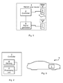
- Fig 1 is a schematic diagram showing functional modules of a continuous wave frequency-modulated (FMCW) radar device 1.
- FMCW radar is a short range measuring radar capable of determining distance.
- the FMCW radar devices provide high reliability by providing distance measurement along with speed measurement.
- This kind of radar device may be used as an early-warning radar, and/or a proximity sensor. Doppler shift is not always required for detection when FM modulation is used.
- the FMCW radar device 1 comprises a controller 2 arranged to control the general operation of the FMCW radar device 1.
- the controller 2 is operatively connected to a signal generator 5.
- the FMCW radar device 1 further comprises a transmitter (Tx) 7.
- the Tx 7 comprises at least one antenna element.
- the signal generators 5 is arranged to, according to instructions provided by the controller 2, generate signals to be transmitted by the Tx 7.
- the FMCW radar device 1 further comprises a receiver (Rx) 6.
- the Rx 6 comprises at least one antenna element.
- the Rx 6 is arranged to receive signals and to provide the received signal to the controller 2.
- the controller 2 is therefore arranged to process received signals. As will be further disclosed below, this arrangement of functional modules enables measurement of the range of the object reflecting the signals by the controller 2.
- the antenna elements of the Tx 7 and Rx 6 may be provided in a radome 8 of the FMCW radar device 1.
- a radio frequency (RF) object detection signal frequency modulated with a given modulation waveform, is transmitted by the Tx 7 towards a target and reflected therefrom back to the FMCW radar device 1 for reception by the Rx 6.
- the reflected signal as received at the Rx 6 is delayed in time, and hence shifted in frequency, from the instantaneous object detection signal by an amount ⁇ proportional to the range R of the target.
- the range R corresponds to the length-wise distance from the FMCW radar device 1 to the target.
- the signal generator 5 is arranged to generate a signal of a known stable frequency continuous wave which varies (up and/or down) in frequency over a fixed period of time by means of a modulating signal. Frequency deviation on the received signal at the Rx 6 increases with distance. The Frequency deviation smears out, or blurs, the Doppler signal. Echoes from a target are then mixed with the transmitted signal to produce a beat signal which will give the distance of the target after demodulation.
- the transmitter frequency can slew up and down according to a sine wave, a sawtooth wave, a triangle wave, a square wave, and the like.
- the range, R, or distance between the target and the FMCW radar device 1 and, additionally, the range rate of the target relative to the FMCW radar device 1 is determined by the measurement of the frequency shift f R .
- the process by which the range is determined is as such well known in the art.
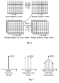
- Fig 5 illustrates the frequency/time structure for a 2D FMCW waveform.
- the frequency/time structure may be represented as an MxN frequency-time matrix. Illustrated in Fig 5 is the basic principle of operation of the FMCW radar device 1 using fast, sampled ramps. During the transmit ramp (shown as an up-chirp), the FMCW radar device 1 mixes the received signal with the locally generated ramp. Time delayed signals and Doppler exhibit themselves as frequency shifts or components on the received signal.
- Fig 6 schematically illustrates matrix processing to transform from a time-frequency representation (top left) to a range and Doppler representation (top right) using a 2D fast Fourier transform (FFT).
- FFT fast Fourier transform
- a matrix of elements from different sub-array elements can then be combined (bottom left) to an LxNxM Doppler sub-array matrix.
- Further signal processing such as FFT based beam forming may then be performed on the Doppler sub-array matrix, resulting in a LxMxN range, Doppler, angle matrix representation (bottom right).
- FFT based beam forming may then be performed on the Doppler sub-array matrix, resulting in a LxMxN range, Doppler, angle matrix representation (bottom right).
- the frequency offset between the ramp and the received echo translates to a Range/Doppler representation after applying a first FFT processing step.
- Doppler and range can then be unambiguously resolved by taking multiple ramps and applying a second FFT processing step across the Doppler dimension (i.e., across the ramps).
- Blocking may be caused by portions of the radio frequency (RF) energy propagating to and from the antenna elements of the Tx 7 and Rx 6 of the FMCW radar device 1 being blocked. That is, blocking may be defined by a physical object being placed so as to cover the field of view of the FMCW radar device 1 (in terms of Tx 7 field of view and/or Rx 6 field of view). Such blockage may, for example, be the result of an accumulation, over a period of time, of foreign matter or objects in the region of an antenna aperture. Such foreign matter may be caused for example by environmental conditions such as temperature, humidity, ice, rain and the like.
- RF radio frequency
- an FMCW radar device 1 In order to obtain blocking detection of the FMCW radar device 1 there is provided an FMCW radar device 1, a method performed by the FMCW radar device 1, a computer program comprising code, for example in the form of a computer program product, that when run on an FMCW radar device 1, causes the FMCW radar device 1 to perform a method of detecting blocking.
- FIG 2 schematically illustrates, in terms of a number of functional modules, the components of the controller functional block 2 of the FMCW radar device 1 illustrated in Fig 1 .
- a processing unit 4 is provided using any combination of one or more of a suitable central processing unit (CPU), multiprocessor, microcontroller, digital signal processor (DSP), application specific integrated circuit (ASIC), field programmable gate arrays (FPGA) etc., capable of executing software instructions stored in a computer program product 10 (as in Fig 4 ), e.g. in the form of a memory 3.
- the memory 3 may also comprise persistent storage, which, for example, can be any single one or combination of magnetic memory, optical memory, solid state memory or even remotely mounted memory.
- the controller 2 controls the general operation of the FMCW radar device 1, e.g. by sending control signals to the signal generator 5 and receiving signals from the Rx 7.
- Other components, as well as the related functionality, of the controller 2 are omitted in order not to obscure the concepts presented herein.
- Figs 10 and 11 are flow charts illustrating embodiments of methods for detecting blocking of an FMCW radar device 1.
- the methods are performed by the FMCW radar device 1.
- the methods are advantageously provided as computer programs 11.
- Fig 4 shows one example of a computer program product 10 comprising computer readable means 12.
- a computer program 11 can be stored, which computer program 11 can cause the controller 2 and thereto operatively coupled entities and devices to execute methods according to embodiments described herein.
- the computer program product 10 is illustrated as an optical disc, such as a CD (compact disc) or a DVD (digital versatile disc) or a Blu-Ray disc.
- the computer program product 10 could also be embodied as a memory, such as a random access memory (RAM), a read-only memory (ROM), an erasable programmable read-only memory (EPROM), or an electrically erasable programmable read-only memory (EEPROM) and more particularly as a non-volatile storage medium of a device in an external memory such as a USB (Universal Serial Bus) memory.
- RAM random access memory
- ROM read-only memory
- EPROM erasable programmable read-only memory
- EEPROM electrically erasable programmable read-only memory
- the computer program 11 is here schematically shown as a track on the depicted optical disk, the computer program 11 can be stored in any way which is suitable for the computer program product 10.
- the inventors of the enclosed embodiments have realized that it is possible to insert a test signal from the signal generator 5 part of the FMCW radar device 1 or turn the Tx 7 on/off at frequency that is within the intermediate frequency (IF) passband that modulates the FMCW ramp to generate offset sideband frequencies.
- a signal representing these sideband frequencies can propagate as a normal transmission waveform through the transmission chain, off a bumper on a vehicle 9, between the antennas of the Tx 7 and Rx 6 through the Rx 6 receiver chain, into the controller 2 and be processed by part or all of already existing signal processing paths.
- This test signal could result in an offset frequency in the Rx 6, effectively shifting up in frequency the zero range (or very close to zero frequency components) that are normally attributed to the bumper return and in a normal system significantly attenuated by a high pass filter.
- the enclosed embodiments are thus based on the understanding that a second signal being a frequency offset signal relative a first signal being a first transmission signal comprising an object detection signal is generated by the FMCW radar device 1. This second signal would impart offset frequency components (side bands etc.) relative the main carrier of the first signal, as illustrated in Fig 7 , and then hence onto the FMCW ramp signal.
- a single carrier frequency (left part) can have two or more side bands (or offset frequencies) representing the second signal (middle part and right part) using common modulation techniques.
- the main carrier can then be ramped (swept in frequency) as disclosed with reference to Fig 5 and the offset modulation tones will sweep also at a fixed offset to the main carrier.
- a method for detecting blocking of a frequency-modulated continuous-wave, FMCW, radar device 1 thus comprises, in a step S3, transmitting a first signal being a first transmission signal.
- the first signal comprises an object detection signal.
- the transmission signal is transmitted by the Tx 7 of the FMCW radar device 1.
- the Tx 7 is further arranged to, in a step S4, transmit a second signal.
- the second signal is a frequency offset signal relative the first signal. In view of the above the second signal embodies the test signal.
- the signals are generated as follows.
- the first signal is generated.
- the first signal may be generated by the signal generator 5.
- the first signal is an up chirp ramp signal or a down chirp ramp signal.
- the second signal is generated from at least two frequency shifted versions of the first signal.
- the second signal may be generated by the signal generator 5.
- Fig 8 illustrates a main ramp frequency and offset "side bands" due to the modulating test tone frequency. Shown here is two-tone modulation (which generate two offset ramps).
- Phase shift keying may be utilized to generate the second signal.
- the second signal may be based on phase shift keying modulation in the Tx path, amplitude modulation using switches (or turning the Tx side on and off) coded pulses or any other modulation scheme.
- steps S1 and S2 are performed prior to steps S3 and S4.
- steps S1 and S2 are performed during a pre-configuration phase of the FMCW radar device 1.
- the first signal and/or the second signal may then be stored in the memory 3 of the controller 2. Either the full signal waveforms are stored in the memory 3 or just the parameters needed to generate the signal waveforms are stored in the memory 3.
- At least the second signal is received by the FMCW radar device 1 as a reception signal.
- the reception signal will depend on objects onto which the signals as transmitted in steps S3 and S4 have reflected.
- the Rx 6 of the FMCW radar device 1 is therefore arranged to, in a step S5, receive a reception signal, where the reception signal comprises at least a received version of the second signal.
- the reception signal may, for example, be received by close in reflections due to close objects. According to an embodiment the reception signal is thus received from device external reflection.
- the reception signal may be subjected to high pass filtering. This is illustrated in Fig 9.
- Fig 9 (a) schematically illustrates a reception signal 13.
- Fig 9 (b) a high pass filter 14 is applied to the reception signal 13.
- reception signal 13 to high pass filtering as in step S6 thus causes low frequency (or distance) components 15 of the reception signal 13 to be attenuated.
- the corresponding high pass filtered signal 13' is illustrated in Fig 9 (c) .
- the low frequency (or distance) components 15 of the reception signal 13 may correspond to contributions in the return signal of the first signal.
- Fig 9 (d) illustrates a reception signal 13" comprising at least a received version of the second signal. Due to close range the frequency offset caused by the modulation of the Tx transmission of the second signal shifts the return of the second signal up in frequency such that the return of the second signal is not attenuated by the high pass 14 characteristics.
- the controller 2 is thus arranged to, in a step S7, determine blocking by identifying a blocking pattern 16 in the received version of the second reception signal.
- the blocking pattern 16 thus corresponds to the return of the second signal (as frequency shifted relative the first signal).
- the FMCW radar device 1 has a field of view.
- the detected blocking may thus provide an indication of transmission from the FMCW radar device i being blocked by a physical object being placed so as to cover the field of view. Absence of the blocking pattern 16 in the reception signal (i.e., where a blocking pattern 16 is not detected) may indicate that there is no blocking.
- the controller 2 is arranged to determine the blocking as in step S7 by performing an optional sub-step S7a of frequency processing an offset frequency component in the reception signal.
- the offset frequency component is indicative of the blocking pattern and is associated with a frequency shifted zero-frequency bin.
- the controller 2 is therefore arranged to determine the blocking as in step S7 (or as in step S7 in combination with step S7a) by performing an optional sub-step S7b of determining the offset frequency component as a deterministic signal received in a single range gate.
- the constant frequency offset may show up as a single (deterministic) signal in a single range gate spread over a number of FFT bins due to interaction with the radome 8 and/or an external object.
- this frequency or group of frequencies that can be examined to determine the clutter or blockage state of the near field of the FMCW radar device 1 as they have effectively been moved from the zero range bin position which would normally be attenuated by the AC coupling in the IF hardware.
- the modulating frequency and waveform may generate a particular range/Doppler pattern that can be determined directly from the modulating parameters.
- Particular range and/or Doppler bins can be examined to see if they contain the components corresponding to the second signal. For example, if the correct pattern of the second signal does not appear whilst the second signal is transmitted it is likely that there is an object blocking at least one of the Tx 7, Rx 6 or radome 8 of the FMCW radar device 1.
- the deterministic signal as determined in step S7b may for example comprise frequency components spread in at least two adjacent frequency range bins and/or Doppler bins.
- the frequency spacing of the tones is determined by the modulating waveform.
- There may also be an amplitude relationship between these tones for example, the tones should all be relative to one another). This may provide further information about the fidelity of the analogue and digital signal processing chain (for example how it is behaving as a function of frequency).
- the second signal therefore comprises at least two positive frequency components, each corresponding to a tone.
- the frequency spacing between the tones may be determined by the modulating waveform of the first signal.
- the step S3 of transmitting the second signal is performed in accordance with the functional safety and reliability requirements of the FMCW radar device 1.
- the Tx 7 may therefore be arranged to, in a step S8, transmit a further first signal being a further first transmission signal, where the further first signal comprises the object detection signal.
- the second signal being the frequency offset signal may then be transmitted at the end of each sensor cycle and/or at power up of the FMCW radar device 1. Further for example, during power up of the FMCW radar device 1 a larger number of transmissions of the second signal may be transmitted in comparison to transmissions of the second signal at the end of a sensor cycle. Thereby transmissions of the second signal during power up may represent more comprehensive blocking detection.
- the step S4 of transmitting the second signal being the frequency offset signal is performed at least during start-up of the FMCW radar device, once every I:th transmission of the further first signal, where I ⁇ 1, and/or once every J:th millisecond during operation of the FMCW radar device, where J ⁇ 1.
- the step of transmitting the second signal is performed 25 times per second.
- the FMCW radar device 1 may be operatively coupled to a weather indication system (not shown).
- the weather indication system may thus provide a weather indication signal to the FMCW radar device 1.
- the controller 2 of the FMCW radar device 1 may thereby be arranged to schedule transmission of the second signal based on the weather indication signal.
- an indication of precipitation such as rain and/or snow
- the second signal may be transmitted more often in cases of a temperature indication of a temperature below the freezing point of water than in cases of a temperature indication of a temperature above the freezing point of water. This may enable enhanced detection of ice or snow in front of the Tx 7.
- the FMCW radar device 1 may be part of a radar arrangement for automotive radars, such as a 77 GHz FMCW radar arrangement. Particularly, the FMCW radar device 1 may be provided in an automotive vehicle 9.
- Fig 3 illustrates an automotive vehicle 9 comprising an FMCW radar device 1.
Landscapes
- Engineering & Computer Science (AREA)
- Radar, Positioning & Navigation (AREA)
- Remote Sensing (AREA)
- Physics & Mathematics (AREA)
- Computer Networks & Wireless Communication (AREA)
- General Physics & Mathematics (AREA)
- Electromagnetism (AREA)
- Radar Systems Or Details Thereof (AREA)
Abstract
Description
- Embodiments presented herein relate to detecting blocking of a radar device, and particularly to detecting blocking of a frequency-modulated continuous-wave, FMCW, radar device.
- Various object detection systems have been proposed to warn drivers of the presence of an object in the path of a movable vehicle. Typically, such warning systems provide a suitable warning signal either audible or visual or both, upon a sensor detecting the presence of an object in the path of the moving vehicle.
- The existence of foreign matter or objects on a radar device such as an automotive radar sensor can impact the accuracy and reliability of the radar device. For example, the foreign matter or objects may undesirably block one or more portions of the radar sensor transmit and/or receive antennas and in particular may block portions of the radio frequency (RF) energy propagating to and from the transmit and receive antennas of the radar sensor.
- Such blockage may, for example, be the result of an accumulation, over a period of time, of foreign matter or objects in the region of an antenna aperture. Such foreign matter may be caused for example by environmental conditions such as temperature, humidity, ice, rain and the like. Such blockage can degrade, or in extreme cases even prevent, proper operation of the automotive radar sensor. If the foreign matter accumulates over time, there is a corresponding gradual decrease in sensor system performance over time. Since the accumulation is gradual, it is sometimes relatively difficult to detect the existence of antenna blockage due to the gradual accumulation of foreign matter and corresponding gradual decrease in radar sensor performance.
- It would, therefore, be desirable to provide a radar device which is capable of detecting blockage. It would also be desirable to provide a radar device which is capable of detecting blockage due to the accumulation of foreign matter, such as mud, ice, snow or the like, on or proximate a radar radome.
- According to
US 2009/0243912 A1 there is provided a blockage detection process which involves detecting a target within a virtual detection zone, accumulating target-related information while the target is within the virtual detection zone and based on the information determining if a blind spot alert signal was missed. The process further includes recording a time of the miss in response to a decision being made that a blind spot alert signal was missed, and based upon information for each recorded miss, determining whether a blockage condition exists. - Hence the blockage detection disclosed in
US 2009/0243912 A1 requires recording of precise time information. Further, this blockage detection process introduces ambiguity since the blockage detection is based determining that a blind spot alert signal indeed was missed. - Hence, there is still a need for improved blocking detection of a radar device.
- An object of embodiments herein is to provide improved blocking detection of a radar device.
- According to a first aspect there is presented a method for detecting blocking of a frequency-modulated continuous-wave, FMCW, radar device. The method comprises transmitting a first signal being a first transmission signal, the first signal comprising an object detection signal. The method comprises transmitting a second signal. The second signal is a frequency offset signal relative the first signal. The method comprises receiving a reception signal. The reception signal comprises at least a received version of the second signal. The method comprises determining blocking by identifying a blocking pattern in the received version of the second reception signal.
- According to a second aspect there is presented a frequency-modulated continuous-wave, FMCW, radar device for detecting blocking of the FMCW radar device. The FMCW radar device comprises a transmitter arranged to transmit a first signal being a first transmission signal. The first signal comprises an object detection signal. The transmitter is further arranged to transmit a second signal. The second signal is a frequency offset signal relative the first signal. The FMCW radar device comprises a receiver arranged to receive a reception signal. The reception signal comprises at least a received version of the second signal. The FMCW radar device comprises a controller arranged to determine blocking by identifying a blocking pattern in the received version of the second reception signal.
- Advantageously this enables accurate detection of blocking. Advantageously the processing can be performed very quickly and when needed.
- According to an embodiment the reception signal is subjected to high pass filtering prior to determining blocking. Advantageously the disclosed blocking detection enables accurate detection of blocking even in the presence of such high pass filtering.
- It may thereby be possible to insert a second signal from the signal generation part of the system that modulates an FMCW ramp to generate offset sideband frequencies. These can propagate through the transmitter chain, between the transmitter and the receiver, through the receiver chain, into the controller and be processed by part, or all, of already existing signal processing paths. The second signal results in a known blocking pattern, the parameters of which are known and can be checked for blocking detection.
- According to a third aspect there is provide an automotive vehicle comprising an FMCW radar device according to the second aspect.
- According to a fourth aspect there is presented a computer program for detecting blocking of a frequency-modulated continuous-wave, FMCW, radar device, the computer program comprising computer program code which, when run on a FMCW radar device, causes the FMCW radar device to perform a method according to the first aspect.
- According to a fifth aspect there is presented a computer program product comprising a computer program according to the third aspect and a computer readable means on which the computer program is stored.
- It is to be noted that any feature of the first, second, third, fourth and fifth aspects may be applied to any other aspect, wherever appropriate. Likewise, any advantage of the first aspect may equally apply to the second, third, fourth, and/or fifth aspect, respectively, and vice versa. Other objectives, features and advantages of the enclosed embodiments will be apparent from the following detailed disclosure, from the attached dependent claims as well as from the drawings.
- Generally, all terms used in the claims are to be interpreted according to their ordinary meaning in the technical field, unless explicitly defined otherwise herein. All references to "a/an/the element, apparatus, component, means, step, etc." are to be interpreted openly as referring to at least one instance of the element, apparatus, component, means, step, etc., unless explicitly stated otherwise. The steps of any method disclosed herein do not have to be performed in the exact order disclosed, unless explicitly stated.
- The invention is now described, by way of example, with reference to the accompanying drawings, in which:
-
Fig 1 is a schematic diagram showing functional modules of an FMCW radar device; -
Fig 2 is a schematic diagram showing functional modules of controller; -
Fig 3 is a schematic diagram showing functional modules of a vehicle; -
Fig 4 shows one example of a computer program product comprising computer readable means; -
Fig 5 schematically illustrates a frequency/time structure for a 2D FMCW waveform; -
Fig 6 schematically illustrates matrix processing; -
Fig 7 schematically illustrates frequency components of a transmission signal; -
Fig 8 schematically illustrates main ramp frequency and offset "side bands" due to modulating test tone frequency; -
Fig 9 schematically illustrates magnitude of a reception signal as a function of distance or frequency; and -
Figs 10 and 11 are flowcharts of methods according to embodiments. - The invention will now be described more fully hereinafter with reference to the accompanying drawings, in which certain embodiments of the invention are shown. This invention may, however, be embodied in many different forms and should not be construed as limited to the embodiments set forth herein; rather, these embodiments are provided by way of example so that this disclosure will be thorough and complete, and will fully convey the scope of the invention to those skilled in the art. Like numbers refer to like elements throughout the description.
-
Fig 1 is a schematic diagram showing functional modules of a continuous wave frequency-modulated (FMCW)radar device 1. In general terms, FMCW radar is a short range measuring radar capable of determining distance. The FMCW radar devices provide high reliability by providing distance measurement along with speed measurement. This kind of radar device may be used as an early-warning radar, and/or a proximity sensor. Doppler shift is not always required for detection when FM modulation is used. - The
FMCW radar device 1 comprises acontroller 2 arranged to control the general operation of theFMCW radar device 1. Thecontroller 2 is operatively connected to asignal generator 5. TheFMCW radar device 1 further comprises a transmitter (Tx) 7. TheTx 7 comprises at least one antenna element. Thesignal generators 5 is arranged to, according to instructions provided by thecontroller 2, generate signals to be transmitted by theTx 7. TheFMCW radar device 1 further comprises a receiver (Rx) 6. TheRx 6 comprises at least one antenna element. TheRx 6 is arranged to receive signals and to provide the received signal to thecontroller 2. Thecontroller 2 is therefore arranged to process received signals. As will be further disclosed below, this arrangement of functional modules enables measurement of the range of the object reflecting the signals by thecontroller 2. The antenna elements of theTx 7 andRx 6 may be provided in aradome 8 of theFMCW radar device 1. - General operations of the
FMCW radar device 1 will now be described. In anFMCW radar device 1, a radio frequency (RF) object detection signal, frequency modulated with a given modulation waveform, is transmitted by theTx 7 towards a target and reflected therefrom back to theFMCW radar device 1 for reception by theRx 6. The reflected signal as received at theRx 6 is delayed in time, and hence shifted in frequency, from the instantaneous object detection signal by an amount τ proportional to the range R of the target. The range R corresponds to the length-wise distance from theFMCW radar device 1 to the target. - The
signal generator 5 is arranged to generate a signal of a known stable frequency continuous wave which varies (up and/or down) in frequency over a fixed period of time by means of a modulating signal. Frequency deviation on the received signal at theRx 6 increases with distance. The Frequency deviation smears out, or blurs, the Doppler signal. Echoes from a target are then mixed with the transmitted signal to produce a beat signal which will give the distance of the target after demodulation. - A variety of modulations are possible; the transmitter frequency can slew up and down according to a sine wave, a sawtooth wave, a triangle wave, a square wave, and the like. For example, when the object detection signal is modulated by a triangular wave form having a peak to peak value of ΔF and a period of 1/fm, the frequency shift, or difference frequency fR, also commonly known as the beat frequency, as generated by a suitable filtered mixer receptive of the reflected signal and a signal indicative of the object detection signal, is equal to the time derivative of the frequency of the object detection signal times the round trip time delay, τ, and may thus be expressed as fR = df/dt. τ = 4R (ΔF·fm)/c,where c is the speed of light. Therefore, the range, R, or distance between the target and the
FMCW radar device 1 and, additionally, the range rate of the target relative to theFMCW radar device 1 is determined by the measurement of the frequency shift fR. The process by which the range is determined is as such well known in the art. -
Fig 5 illustrates the frequency/time structure for a 2D FMCW waveform. The frequency/time structure may be represented as an MxN frequency-time matrix. Illustrated inFig 5 is the basic principle of operation of theFMCW radar device 1 using fast, sampled ramps. During the transmit ramp (shown as an up-chirp), theFMCW radar device 1 mixes the received signal with the locally generated ramp. Time delayed signals and Doppler exhibit themselves as frequency shifts or components on the received signal.Fig 6 schematically illustrates matrix processing to transform from a time-frequency representation (top left) to a range and Doppler representation (top right) using a 2D fast Fourier transform (FFT). Also shown by way of example is further signal processing that is often carried out on the resulting range-Doppler matrix for illustration. A matrix of elements from different sub-array elements can then be combined (bottom left) to an LxNxM Doppler sub-array matrix. Further signal processing such as FFT based beam forming may then be performed on the Doppler sub-array matrix, resulting in a LxMxN range, Doppler, angle matrix representation (bottom right). For one ramp, the frequency offset between the ramp and the received echo translates to a Range/Doppler representation after applying a first FFT processing step. In general, Doppler and range can then be unambiguously resolved by taking multiple ramps and applying a second FFT processing step across the Doppler dimension (i.e., across the ramps). - The embodiments disclosed herein relate to detecting blocking of the
FMCW radar device 1. Blocking may be caused by portions of the radio frequency (RF) energy propagating to and from the antenna elements of theTx 7 andRx 6 of theFMCW radar device 1 being blocked. That is, blocking may be defined by a physical object being placed so as to cover the field of view of the FMCW radar device 1 (in terms ofTx 7 field of view and/orRx 6 field of view). Such blockage may, for example, be the result of an accumulation, over a period of time, of foreign matter or objects in the region of an antenna aperture. Such foreign matter may be caused for example by environmental conditions such as temperature, humidity, ice, rain and the like. In order to obtain blocking detection of theFMCW radar device 1 there is provided anFMCW radar device 1, a method performed by theFMCW radar device 1, a computer program comprising code, for example in the form of a computer program product, that when run on anFMCW radar device 1, causes theFMCW radar device 1 to perform a method of detecting blocking. -
Fig 2 schematically illustrates, in terms of a number of functional modules, the components of the controllerfunctional block 2 of theFMCW radar device 1 illustrated inFig 1 . Aprocessing unit 4 is provided using any combination of one or more of a suitable central processing unit (CPU), multiprocessor, microcontroller, digital signal processor (DSP), application specific integrated circuit (ASIC), field programmable gate arrays (FPGA) etc., capable of executing software instructions stored in a computer program product 10 (as inFig 4 ), e.g. in the form of amemory 3. Thus theprocessing unit 4 is thereby arranged to execute methods as herein disclosed. Thememory 3 may also comprise persistent storage, which, for example, can be any single one or combination of magnetic memory, optical memory, solid state memory or even remotely mounted memory. Thecontroller 2 controls the general operation of theFMCW radar device 1, e.g. by sending control signals to thesignal generator 5 and receiving signals from theRx 7. Other components, as well as the related functionality, of thecontroller 2 are omitted in order not to obscure the concepts presented herein. -
Figs 10 and 11 are flow charts illustrating embodiments of methods for detecting blocking of anFMCW radar device 1. The methods are performed by theFMCW radar device 1. The methods are advantageously provided ascomputer programs 11.Fig 4 shows one example of acomputer program product 10 comprising computerreadable means 12. On this computer readable means 12, acomputer program 11 can be stored, whichcomputer program 11 can cause thecontroller 2 and thereto operatively coupled entities and devices to execute methods according to embodiments described herein. In the example ofFig 4 , thecomputer program product 10 is illustrated as an optical disc, such as a CD (compact disc) or a DVD (digital versatile disc) or a Blu-Ray disc. Thecomputer program product 10 could also be embodied as a memory, such as a random access memory (RAM), a read-only memory (ROM), an erasable programmable read-only memory (EPROM), or an electrically erasable programmable read-only memory (EEPROM) and more particularly as a non-volatile storage medium of a device in an external memory such as a USB (Universal Serial Bus) memory. Thus, while thecomputer program 11 is here schematically shown as a track on the depicted optical disk, thecomputer program 11 can be stored in any way which is suitable for thecomputer program product 10. - The inventors of the enclosed embodiments have realized that it is possible to insert a test signal from the
signal generator 5 part of theFMCW radar device 1 or turn theTx 7 on/off at frequency that is within the intermediate frequency (IF) passband that modulates the FMCW ramp to generate offset sideband frequencies. A signal representing these sideband frequencies can propagate as a normal transmission waveform through the transmission chain, off a bumper on avehicle 9, between the antennas of theTx 7 andRx 6 through theRx 6 receiver chain, into thecontroller 2 and be processed by part or all of already existing signal processing paths. This test signal could result in an offset frequency in theRx 6, effectively shifting up in frequency the zero range (or very close to zero frequency components) that are normally attributed to the bumper return and in a normal system significantly attenuated by a high pass filter. The enclosed embodiments are thus based on the understanding that a second signal being a frequency offset signal relative a first signal being a first transmission signal comprising an object detection signal is generated by theFMCW radar device 1. This second signal would impart offset frequency components (side bands etc.) relative the main carrier of the first signal, as illustrated inFig 7 , and then hence onto the FMCW ramp signal. As schematically illustrated inFig 7 a single carrier frequency (left part) can have two or more side bands (or offset frequencies) representing the second signal (middle part and right part) using common modulation techniques. The main carrier can then be ramped (swept in frequency) as disclosed with reference toFig 5 and the offset modulation tones will sweep also at a fixed offset to the main carrier. - A method for detecting blocking of a frequency-modulated continuous-wave, FMCW,
radar device 1 thus comprises, in a step S3, transmitting a first signal being a first transmission signal. The first signal comprises an object detection signal. The transmission signal is transmitted by theTx 7 of theFMCW radar device 1. TheTx 7 is further arranged to, in a step S4, transmit a second signal. The second signal is a frequency offset signal relative the first signal. In view of the above the second signal embodies the test signal. - There may be different ways of generating the first and second signals, respectively. According to an embodiment the signals are generated as follows. In a step S1 the first signal is generated. The first signal may be generated by the
signal generator 5. According to an embodiment the first signal is an up chirp ramp signal or a down chirp ramp signal. In a step S2 the second signal is generated from at least two frequency shifted versions of the first signal. The second signal may be generated by thesignal generator 5. In more detail,Fig 8 illustrates a main ramp frequency and offset "side bands" due to the modulating test tone frequency. Shown here is two-tone modulation (which generate two offset ramps). - Phase shift keying may be utilized to generate the second signal. In general terms, the second signal may be based on phase shift keying modulation in the Tx path, amplitude modulation using switches (or turning the Tx side on and off) coded pulses or any other modulation scheme. According to an embodiment steps S1 and S2 are performed prior to steps S3 and S4. According to an embodiment steps S1 and S2 are performed during a pre-configuration phase of the
FMCW radar device 1. The first signal and/or the second signal may then be stored in thememory 3 of thecontroller 2. Either the full signal waveforms are stored in thememory 3 or just the parameters needed to generate the signal waveforms are stored in thememory 3. - At least the second signal is received by the
FMCW radar device 1 as a reception signal. In general terms the reception signal will depend on objects onto which the signals as transmitted in steps S3 and S4 have reflected. TheRx 6 of theFMCW radar device 1 is therefore arranged to, in a step S5, receive a reception signal, where the reception signal comprises at least a received version of the second signal. The reception signal may, for example, be received by close in reflections due to close objects. According to an embodiment the reception signal is thus received from device external reflection. In an optional step S6 the reception signal may be subjected to high pass filtering. This is illustrated inFig 9. Fig 9 (a) schematically illustrates areception signal 13. InFig 9 (b) ahigh pass filter 14 is applied to thereception signal 13. Subjecting thereception signal 13 to high pass filtering as in step S6 thus causes low frequency (or distance)components 15 of thereception signal 13 to be attenuated. The corresponding high pass filtered signal 13' is illustrated inFig 9 (c) . The low frequency (or distance)components 15 of thereception signal 13 may correspond to contributions in the return signal of the first signal. Thus, due to the attenuation of the reception signal 13' inFig 9 (c) it may be difficult to determine blocking based on an analysis of thecomponents 15 of the attenuated reception signal 13' corresponding to contributions in the return signal of the first signal.Fig 9 (d) , on the other hand, illustrates areception signal 13" comprising at least a received version of the second signal. Due to close range the frequency offset caused by the modulation of the Tx transmission of the second signal shifts the return of the second signal up in frequency such that the return of the second signal is not attenuated by thehigh pass 14 characteristics. - The
controller 2 is thus arranged to, in a step S7, determine blocking by identifying a blockingpattern 16 in the received version of the second reception signal. The blockingpattern 16 thus corresponds to the return of the second signal (as frequency shifted relative the first signal). In general terms theFMCW radar device 1 has a field of view. The detected blocking may thus provide an indication of transmission from the FMCW radar device i being blocked by a physical object being placed so as to cover the field of view. Absence of the blockingpattern 16 in the reception signal (i.e., where a blockingpattern 16 is not detected) may indicate that there is no blocking. - According to an embodiment the
controller 2 is arranged to determine the blocking as in step S7 by performing an optional sub-step S7a of frequency processing an offset frequency component in the reception signal. The offset frequency component is indicative of the blocking pattern and is associated with a frequency shifted zero-frequency bin. When the reception signal is processed in a normal way by the controller 2 (i.e. as a normal reception signal) performing FFT1 processing, the constant frequency offset shows up as a single (deterministic) signal in a single range gate. According to an embodiment thecontroller 2 is therefore arranged to determine the blocking as in step S7 (or as in step S7 in combination with step S7a) by performing an optional sub-step S7b of determining the offset frequency component as a deterministic signal received in a single range gate. The constant frequency offset may show up as a single (deterministic) signal in a single range gate spread over a number of FFT bins due to interaction with theradome 8 and/or an external object. Thus, it is this frequency or group of frequencies that can be examined to determine the clutter or blockage state of the near field of theFMCW radar device 1 as they have effectively been moved from the zero range bin position which would normally be attenuated by the AC coupling in the IF hardware. - The modulating frequency and waveform may generate a particular range/Doppler pattern that can be determined directly from the modulating parameters. Particular range and/or Doppler bins can be examined to see if they contain the components corresponding to the second signal. For example, if the correct pattern of the second signal does not appear whilst the second signal is transmitted it is likely that there is an object blocking at least one of the
Tx 7,Rx 6 orradome 8 of theFMCW radar device 1. The deterministic signal as determined in step S7b may for example comprise frequency components spread in at least two adjacent frequency range bins and/or Doppler bins. - In general terms, the frequency spacing of the tones (therefore the range bin they appear in) is determined by the modulating waveform. There may also be an amplitude relationship between these tones (for example, the tones should all be relative to one another). This may provide further information about the fidelity of the analogue and digital signal processing chain (for example how it is behaving as a function of frequency). According to embodiments the second signal therefore comprises at least two positive frequency components, each corresponding to a tone. The frequency spacing between the tones may be determined by the modulating waveform of the first signal.
- In general terms the step S3 of transmitting the second signal is performed in accordance with the functional safety and reliability requirements of the
FMCW radar device 1. TheTx 7 may therefore be arranged to, in a step S8, transmit a further first signal being a further first transmission signal, where the further first signal comprises the object detection signal. The second signal being the frequency offset signal may then be transmitted at the end of each sensor cycle and/or at power up of theFMCW radar device 1. Further for example, during power up of the FMCW radar device 1 a larger number of transmissions of the second signal may be transmitted in comparison to transmissions of the second signal at the end of a sensor cycle. Thereby transmissions of the second signal during power up may represent more comprehensive blocking detection. According to an embodiment the step S4 of transmitting the second signal being the frequency offset signal is performed at least during start-up of the FMCW radar device, once every I:th transmission of the further first signal, where I ≥ 1, and/or once every J:th millisecond during operation of the FMCW radar device, where J ≥ 1. According to one embodiment the step of transmitting the second signal is performed 25 times per second. - For example, the
FMCW radar device 1 may be operatively coupled to a weather indication system (not shown). The weather indication system may thus provide a weather indication signal to theFMCW radar device 1. Thecontroller 2 of theFMCW radar device 1 may thereby be arranged to schedule transmission of the second signal based on the weather indication signal. For example an indication of precipitation, such as rain and/or snow, may result in the second signal being transmitted more often than in cases an indication of no precipitation is received. This may enable enhanced detection of water (such as ice or snow) or mud in front of theTx 7. For example the second signal may be transmitted more often in cases of a temperature indication of a temperature below the freezing point of water than in cases of a temperature indication of a temperature above the freezing point of water. This may enable enhanced detection of ice or snow in front of theTx 7. - The
FMCW radar device 1 may be part of a radar arrangement for automotive radars, such as a 77 GHz FMCW radar arrangement. Particularly, theFMCW radar device 1 may be provided in anautomotive vehicle 9.Fig 3 illustrates anautomotive vehicle 9 comprising anFMCW radar device 1. - The invention has mainly been described above with reference to a few embodiments. However, as is readily appreciated by a person skilled in the art, other embodiments than the ones disclosed above are equally possible within the scope of the invention, as defined by the appended patent claims.
Claims (15)
- A method for detecting blocking of a frequency-modulated continuous-wave, FMCW, radar device (1), comprising:transmitting (S3) a first signal being a first transmission signal, the first signal comprising an object detection signal;transmitting (S4) a second signal being a frequency offset signal relative the first signal;receiving (S5) a reception signal (13, 13', 13"), the reception signal comprising at least a received version of the second signal; anddetermining (S7) blocking by identifying a blocking pattern (16) in the received version of the second reception signal.
- The method according to claim 1, further comprising:subjecting (S6) the reception signal to high pass filtering (14) prior to determining blocking.
- The method according to claim 1 or 2, wherein determining blocking further comprises:frequency processing (S7a) an offset frequency component in the reception signal, the offset frequency component being indicative of the blocking pattern and associated with a frequency shifted zero-frequency bin.
- The method according to any one of the preceding claims, wherein determining blocking further comprises:determining (S7b) the offset frequency component as a deterministic signal received in a single range gate.
- The method according to claim 4, wherein the deterministic signal comprises frequency components spread in at least two adjacent frequency range bins and/or Doppler bins.
- The method according to any one of the preceding claims, wherein the FMCW radar device has a field of view, and wherein the detected blocking provides an indication of transmission from said FMCW radar device being blocked by a physical object being placed so as to cover said field of view.
- The method according to any one of the preceding claims, further comprising, prior to transmitting the first signal and the second signal:generating (S1) the first signal; andgenerating (S2) the second signal from at least two frequency shifted versions of said first signal.
- The method according to claim 7, wherein phase shift keying is utilized to generate the second signal.
- The method according to any one of the preceding claims, wherein the first signal is an up chirp ramp signal or a down chirp ramp signal.
- The method according to any one of the preceding claims, wherein the reception signal is received from device external reflection.
- The method according to any one of the preceding claims, further comprising:transmitting (S8) a further first signal being a further first transmission signal, the further first signal comprising the object detection signal; andwherein the step of transmitting the second signal being the frequency offset signal is performed at least during start-up of the FMCW radar device, once every I:th transmission of the further first signal, where I ≥ 1, and/or once every J:th millisecond during operation of the FMCW radar device, where J ≥ 1.
- A frequency-modulated continuous-wave, FMCW, radar device (1) for detecting blocking of the FMCW radar device, comprising:a transmitter (7) arranged to transmit a first signal being a first transmission signal, the first signal comprising an object detection signal;the transmitter (7) further being arranged to transmit a second signal being a frequency offset signal relative the first signal;a receiver (6) arranged to receive a reception signal (13, 13', 13"), the reception signal comprising at least a received version of the second signal; anda controller (2) arranged to determine blocking by identifying a blocking pattern (16) in the received version of the second reception signal.
- An automotive vehicle (9) comprising an FMCW radar device according to claim 12.
- A computer program (11) for detecting blocking of a frequency-modulated continuous-wave, FMCW, radar device, the computer program comprising computer program code which, when run on an FMCW radar device (1), causes the FMCW radar device to:transmit (S3) a first signal being a first transmission signal, the first signal comprising an object detection signal;transmit (S4) a second signal being a frequency offset signal relative the first signal;receive (S5) a reception signal (13, 13', 13"), the reception signal comprising at least a received version of the second signal; anddetermine (S7) blocking by identifying a blocking pattern (16) in the received version of the second reception signal.
- A computer program product (10) comprising a computer program (11) according to claim 14 and a computer readable means (12) on which the computer program is stored.
Priority Applications (4)
| Application Number | Priority Date | Filing Date | Title |
|---|---|---|---|
| EP13168943.2A EP2806286B1 (en) | 2013-05-23 | 2013-05-23 | FMCW radar blocking detection |
| PCT/SE2014/050601 WO2014189443A1 (en) | 2013-05-23 | 2014-05-16 | Fmcw radar blocking detection |
| JP2016515313A JP6375092B2 (en) | 2013-05-23 | 2014-05-16 | FMCW radar blocking detection |
| US14/892,638 US10267897B2 (en) | 2013-05-23 | 2014-05-16 | FMCW radar blocking detection |
Applications Claiming Priority (1)
| Application Number | Priority Date | Filing Date | Title |
|---|---|---|---|
| EP13168943.2A EP2806286B1 (en) | 2013-05-23 | 2013-05-23 | FMCW radar blocking detection |
Publications (2)
| Publication Number | Publication Date |
|---|---|
| EP2806286A1 true EP2806286A1 (en) | 2014-11-26 |
| EP2806286B1 EP2806286B1 (en) | 2019-07-10 |
Family
ID=48482949
Family Applications (1)
| Application Number | Title | Priority Date | Filing Date |
|---|---|---|---|
| EP13168943.2A Active EP2806286B1 (en) | 2013-05-23 | 2013-05-23 | FMCW radar blocking detection |
Country Status (4)
| Country | Link |
|---|---|
| US (1) | US10267897B2 (en) |
| EP (1) | EP2806286B1 (en) |
| JP (1) | JP6375092B2 (en) |
| WO (1) | WO2014189443A1 (en) |
Cited By (3)
| Publication number | Priority date | Publication date | Assignee | Title |
|---|---|---|---|---|
| EP3153875A1 (en) * | 2015-10-06 | 2017-04-12 | Autoliv Development AB | A modular vehicle radar |
| WO2021122167A1 (en) | 2019-12-20 | 2021-06-24 | HELLA GmbH & Co. KGaA | Method for checking a radar sensor of a vehicle |
| WO2022029182A1 (en) * | 2020-08-05 | 2022-02-10 | Universitat Rovira I Virgili | Device and method for vehicle-to-vehicle and vehicle-to-infrastructure communication |
Families Citing this family (26)
| Publication number | Priority date | Publication date | Assignee | Title |
|---|---|---|---|---|
| US10036812B2 (en) | 2015-06-24 | 2018-07-31 | Blackmore Sensors and Analytics Inc. | Method and system for three dimensional digital holographic aperture synthesis |
| US10324166B2 (en) * | 2015-09-28 | 2019-06-18 | Rockwell Collins, Inc. | Affordable combined pulsed/FMCW radar AESA |
| DE102016108756A1 (en) * | 2016-05-12 | 2017-11-16 | Valeo Schalter Und Sensoren Gmbh | Radar sensor device for a motor vehicle, driver assistance system, motor vehicle and method for detecting an object |
| EP3290946B1 (en) * | 2016-09-02 | 2019-08-14 | Preco Electronics, LLC | Monitoring and alert apparatus for radome performance affected by dirt or debris |
| US10408921B2 (en) * | 2016-10-28 | 2019-09-10 | Ford Global Technologies, Llc | Vehicle detection of external objects |
| EP3548840B1 (en) | 2016-11-29 | 2023-10-11 | Blackmore Sensors & Analytics, LLC | Method and system for classification of an object in a point cloud data set |
| US11624828B2 (en) | 2016-11-30 | 2023-04-11 | Blackmore Sensors & Analytics, Llc | Method and system for adaptive scanning with optical ranging systems |
| KR102254466B1 (en) | 2016-11-30 | 2021-05-20 | 블랙모어 센서스 앤드 애널리틱스, 엘엘씨 | Automatic real-time adaptive scanning method and system using optical distance measurement system |
| KR102399757B1 (en) * | 2016-11-30 | 2022-05-18 | 블랙모어 센서스 앤드 애널리틱스, 엘엘씨 | Method and system for doppler detection and doppler correction of optical chirped range detection |
| US10422880B2 (en) | 2017-02-03 | 2019-09-24 | Blackmore Sensors and Analytics Inc. | Method and system for doppler detection and doppler correction of optical phase-encoded range detection |
| DE102017102592A1 (en) | 2017-02-09 | 2018-08-09 | Valeo Schalter Und Sensoren Gmbh | Method for operating a radar sensor of a motor vehicle with storage of a filter coefficient, radar sensor, driver assistance system and motor vehicle |
| US10401495B2 (en) | 2017-07-10 | 2019-09-03 | Blackmore Sensors and Analytics Inc. | Method and system for time separated quadrature detection of doppler effects in optical range measurements |
| US10534084B2 (en) | 2017-07-27 | 2020-01-14 | Blackmore Sensors & Analytics, Llc | Method and system for using square wave digital chirp signal for optical chirped range detection |
| DE102017221120B4 (en) * | 2017-11-27 | 2025-03-27 | Zf Friedrichshafen Ag | Evaluation procedure for RADAR measurement data from a mobile RADAR measurement system |
| RU180812U1 (en) * | 2018-02-06 | 2018-06-22 | Федеральное государственное бюджетное образовательное учреждение высшего образования "МИРЭА - Российский технологический университет" | INTERSEQUENT REGENERATOR OF QUASI-STATIONARY SEQUENCE OF SUBNANOSECOND RADIO PULSES |
| EP4246176A3 (en) | 2018-04-23 | 2023-12-13 | Blackmore Sensors & Analytics, LLC | Method and system for controlling autonomous vehicle using coherent range doppler optical sensors |
| JP7173785B2 (en) * | 2018-08-09 | 2022-11-16 | 株式会社デンソーテン | Target detection device and target detection method |
| US11822010B2 (en) | 2019-01-04 | 2023-11-21 | Blackmore Sensors & Analytics, Llc | LIDAR system |
| CN113260873A (en) | 2019-01-04 | 2021-08-13 | 布莱克莫尔传感器和分析有限责任公司 | LIDAR device with rotatable polygonal deflector having refractive facets |
| US11782148B2 (en) * | 2019-03-25 | 2023-10-10 | Texas Instruments Incorporated | Radar system |
| US20210149018A1 (en) * | 2019-11-18 | 2021-05-20 | Semiconductor Components Industries, Llc | Minimizing phase noise in fmcw radar and detecting radar housing coating |
| DE102020215039A1 (en) | 2020-11-30 | 2022-06-02 | Robert Bosch Gesellschaft mit beschränkter Haftung | LiDAR sensor system |
| DE102021201283A1 (en) | 2021-02-11 | 2022-08-11 | Robert Bosch Gesellschaft mit beschränkter Haftung | Method for determining distance and/or speed for an FMCW LiDAR sensor |
| GB2625179B (en) * | 2021-03-15 | 2025-03-12 | Mitsubishi Electric Corp | Radar device |
| US12130363B2 (en) | 2022-02-03 | 2024-10-29 | Aurora Operations, Inc. | LIDAR system |
| US12571914B2 (en) | 2023-10-05 | 2026-03-10 | Aurora Operations, Inc. | Systems and methods of LIDAR sensor systems having amplifier protection circuits |
Citations (4)
| Publication number | Priority date | Publication date | Assignee | Title |
|---|---|---|---|---|
| US6611227B1 (en) * | 2002-08-08 | 2003-08-26 | Raytheon Company | Automotive side object detection sensor blockage detection system and related techniques |
| US20060227037A1 (en) * | 2005-04-12 | 2006-10-12 | Honda Motor Co., Ltd. | Object sensing apparatus |
| US20090243912A1 (en) | 2008-03-31 | 2009-10-01 | Lohmeier Stephen P | Automotive Radar Sensor Blockage Detection System and Related Techniques |
| EP2392944A1 (en) * | 2010-06-04 | 2011-12-07 | Robert Bosch GmbH | Radar sensor and method for detection precipitation with a radar sensor |
Family Cites Families (17)
| Publication number | Priority date | Publication date | Assignee | Title |
|---|---|---|---|---|
| JPH0634754A (en) * | 1992-07-20 | 1994-02-10 | Fujitsu Ten Ltd | Radar equipment |
| US5432516A (en) * | 1994-01-13 | 1995-07-11 | Armatron International, Inc. | Radar obstacle detection system with self test |
| JP3347012B2 (en) * | 1997-04-03 | 2002-11-20 | 本田技研工業株式会社 | FM radar equipment |
| US5959570A (en) * | 1997-11-21 | 1999-09-28 | Raytheon Company | Automotive forward looking sensor blockage detection system and related techniques |
| JP3428009B2 (en) * | 1998-07-03 | 2003-07-22 | トヨタ自動車株式会社 | Radar equipment for vehicles |
| US6469659B1 (en) * | 2001-05-03 | 2002-10-22 | Delphi Technologies, Inc. | Apparatus and method for detecting radar obstruction |
| US6686872B2 (en) * | 2001-08-10 | 2004-02-03 | Honeywell International Inc. | System and method for in-place, automated detection of radome condition |
| DE10207437A1 (en) * | 2002-02-22 | 2003-09-11 | Bosch Gmbh Robert | Radar sensor for motor vehicles |
| JP4447389B2 (en) * | 2004-07-09 | 2010-04-07 | 本田技研工業株式会社 | Radar apparatus and vehicle control apparatus including the radar apparatus |
| JP2007051888A (en) * | 2005-08-16 | 2007-03-01 | Mitsubishi Electric Corp | Radar equipment |
| JP2007108028A (en) | 2005-10-14 | 2007-04-26 | Mitsubishi Electric Corp | In-vehicle radar system |
| DE102007016869A1 (en) | 2007-04-10 | 2008-10-23 | Robert Bosch Gmbh | Method for detecting losses on a radiated surface of a radar sensor, radar sensor and driver assistance system with such a radar sensor |
| JP5319145B2 (en) * | 2008-03-25 | 2013-10-16 | 株式会社東芝 | Radar device and control method of radar device |
| DE102008054624A1 (en) * | 2008-12-15 | 2010-06-17 | Robert Bosch Gmbh | FMCW radar sensor for motor vehicles |
| DE102009001231A1 (en) * | 2009-02-27 | 2010-09-02 | Robert Bosch Gmbh | FMCW radar detector with device for detecting a radar situation |
| DE102009001265A1 (en) * | 2009-03-02 | 2010-09-09 | Robert Bosch Gmbh | Radar sensor with Blinheitserkennungseinrichtung |
| US8441394B2 (en) * | 2011-07-11 | 2013-05-14 | Delphi Technologies, Inc. | System and method for detecting obstructions and misalignment of ground vehicle radar systems |
-
2013
- 2013-05-23 EP EP13168943.2A patent/EP2806286B1/en active Active
-
2014
- 2014-05-16 US US14/892,638 patent/US10267897B2/en active Active
- 2014-05-16 JP JP2016515313A patent/JP6375092B2/en not_active Expired - Fee Related
- 2014-05-16 WO PCT/SE2014/050601 patent/WO2014189443A1/en not_active Ceased
Patent Citations (4)
| Publication number | Priority date | Publication date | Assignee | Title |
|---|---|---|---|---|
| US6611227B1 (en) * | 2002-08-08 | 2003-08-26 | Raytheon Company | Automotive side object detection sensor blockage detection system and related techniques |
| US20060227037A1 (en) * | 2005-04-12 | 2006-10-12 | Honda Motor Co., Ltd. | Object sensing apparatus |
| US20090243912A1 (en) | 2008-03-31 | 2009-10-01 | Lohmeier Stephen P | Automotive Radar Sensor Blockage Detection System and Related Techniques |
| EP2392944A1 (en) * | 2010-06-04 | 2011-12-07 | Robert Bosch GmbH | Radar sensor and method for detection precipitation with a radar sensor |
Cited By (3)
| Publication number | Priority date | Publication date | Assignee | Title |
|---|---|---|---|---|
| EP3153875A1 (en) * | 2015-10-06 | 2017-04-12 | Autoliv Development AB | A modular vehicle radar |
| WO2021122167A1 (en) | 2019-12-20 | 2021-06-24 | HELLA GmbH & Co. KGaA | Method for checking a radar sensor of a vehicle |
| WO2022029182A1 (en) * | 2020-08-05 | 2022-02-10 | Universitat Rovira I Virgili | Device and method for vehicle-to-vehicle and vehicle-to-infrastructure communication |
Also Published As
| Publication number | Publication date |
|---|---|
| WO2014189443A1 (en) | 2014-11-27 |
| JP2016524707A (en) | 2016-08-18 |
| US10267897B2 (en) | 2019-04-23 |
| EP2806286B1 (en) | 2019-07-10 |
| JP6375092B2 (en) | 2018-08-15 |
| US20160091599A1 (en) | 2016-03-31 |
Similar Documents
| Publication | Publication Date | Title |
|---|---|---|
| US10267897B2 (en) | FMCW radar blocking detection | |
| US9910135B2 (en) | FMCW radar self-test | |
| EP2884299B1 (en) | Speed determination of a target | |
| US8823582B2 (en) | FMCW radar sensor system having a device for detecting a radome coating | |
| US6606052B1 (en) | Method and apparatus for detecting multiple objects with frequency modulated continuous wave radar | |
| EP2584373B1 (en) | Radar device | |
| US8334800B2 (en) | On-vehicle radar device | |
| EP1925948B1 (en) | Radar apparatus and signal processing method | |
| US9063225B2 (en) | High resolution Doppler collision avoidance radar | |
| KR20190096291A (en) | Rader sensing with phase correction | |
| US11099269B2 (en) | Radar device for vehicle and target determination method therefor | |
| US7714771B2 (en) | Method and device for measuring the distance and relative speed of multiple objects | |
| JP2020067455A (en) | Fmcw radar for suppressing disturbing signal | |
| US10473760B2 (en) | Radar device and vertical axis-misalignment detecting method | |
| CN104280729A (en) | Frequency-modulated continuous-wave radar device and object detecting method using continuous wave | |
| EP3655797B1 (en) | Apparatus and method for detecting and correcting for blockage of an automotive radar sensor | |
| US20020163463A1 (en) | Apparatus and method for detecting radar obstruction | |
| EP3460506A1 (en) | Method for monitoring the performance range of an automotive radar system | |
| KR20130099310A (en) | Fmcw radar system usign adaptive scheduler | |
| KR101188285B1 (en) | Method and apparatus for detecting moving target | |
| RU2668275C2 (en) | Method for detecting blockage of vehicle antenna | |
| EP4538734A1 (en) | Transmit power control for automotive radar sensing | |
| Noor et al. | MIMO FM-CW radar using beat signal averaging method | |
| El-Mokdad et al. | FMCW implementation on LABVIEW | |
| Dogan | Multistatic Radar Imaging for Traffic Monitoring |
Legal Events
| Date | Code | Title | Description |
|---|---|---|---|
| PUAI | Public reference made under article 153(3) epc to a published international application that has entered the european phase |
Free format text: ORIGINAL CODE: 0009012 |
|
| 17P | Request for examination filed |
Effective date: 20130523 |
|
| AK | Designated contracting states |
Kind code of ref document: A1 Designated state(s): AL AT BE BG CH CY CZ DE DK EE ES FI FR GB GR HR HU IE IS IT LI LT LU LV MC MK MT NL NO PL PT RO RS SE SI SK SM TR |
|
| AX | Request for extension of the european patent |
Extension state: BA ME |
|
| R17P | Request for examination filed (corrected) |
Effective date: 20150521 |
|
| RBV | Designated contracting states (corrected) |
Designated state(s): AL AT BE BG CH CY CZ DE DK EE ES FI FR GB GR HR HU IE IS IT LI LT LU LV MC MK MT NL NO PL PT RO RS SE SI SK SM TR |
|
| STAA | Information on the status of an ep patent application or granted ep patent |
Free format text: STATUS: EXAMINATION IS IN PROGRESS |
|
| 17Q | First examination report despatched |
Effective date: 20180727 |
|
| RAP1 | Party data changed (applicant data changed or rights of an application transferred) |
Owner name: VEONEER SWEDEN AB |
|
| GRAJ | Information related to disapproval of communication of intention to grant by the applicant or resumption of examination proceedings by the epo deleted |
Free format text: ORIGINAL CODE: EPIDOSDIGR1 |
|
| STAA | Information on the status of an ep patent application or granted ep patent |
Free format text: STATUS: GRANT OF PATENT IS INTENDED |
|
| GRAP | Despatch of communication of intention to grant a patent |
Free format text: ORIGINAL CODE: EPIDOSNIGR1 |
|
| INTG | Intention to grant announced |
Effective date: 20190108 |
|
| GRAS | Grant fee paid |
Free format text: ORIGINAL CODE: EPIDOSNIGR3 |
|
| GRAA | (expected) grant |
Free format text: ORIGINAL CODE: 0009210 |
|
| STAA | Information on the status of an ep patent application or granted ep patent |
Free format text: STATUS: THE PATENT HAS BEEN GRANTED |
|
| AK | Designated contracting states |
Kind code of ref document: B1 Designated state(s): AL AT BE BG CH CY CZ DE DK EE ES FI FR GB GR HR HU IE IS IT LI LT LU LV MC MK MT NL NO PL PT RO RS SE SI SK SM TR |
|
| REG | Reference to a national code |
Ref country code: GB Ref legal event code: FG4D |
|
| REG | Reference to a national code |
Ref country code: CH Ref legal event code: EP Ref country code: AT Ref legal event code: REF Ref document number: 1154164 Country of ref document: AT Kind code of ref document: T Effective date: 20190715 |
|
| REG | Reference to a national code |
Ref country code: DE Ref legal event code: R096 Ref document number: 602013057585 Country of ref document: DE |
|
| REG | Reference to a national code |
Ref country code: IE Ref legal event code: FG4D |
|
| REG | Reference to a national code |
Ref country code: SE Ref legal event code: TRGR |
|
| REG | Reference to a national code |
Ref country code: NL Ref legal event code: MP Effective date: 20190710 |
|
| REG | Reference to a national code |
Ref country code: LT Ref legal event code: MG4D |
|
| REG | Reference to a national code |
Ref country code: AT Ref legal event code: MK05 Ref document number: 1154164 Country of ref document: AT Kind code of ref document: T Effective date: 20190710 |
|
| PG25 | Lapsed in a contracting state [announced via postgrant information from national office to epo] |
Ref country code: AT Free format text: LAPSE BECAUSE OF FAILURE TO SUBMIT A TRANSLATION OF THE DESCRIPTION OR TO PAY THE FEE WITHIN THE PRESCRIBED TIME-LIMIT Effective date: 20190710 Ref country code: NL Free format text: LAPSE BECAUSE OF FAILURE TO SUBMIT A TRANSLATION OF THE DESCRIPTION OR TO PAY THE FEE WITHIN THE PRESCRIBED TIME-LIMIT Effective date: 20190710 Ref country code: NO Free format text: LAPSE BECAUSE OF FAILURE TO SUBMIT A TRANSLATION OF THE DESCRIPTION OR TO PAY THE FEE WITHIN THE PRESCRIBED TIME-LIMIT Effective date: 20191010 Ref country code: BG Free format text: LAPSE BECAUSE OF FAILURE TO SUBMIT A TRANSLATION OF THE DESCRIPTION OR TO PAY THE FEE WITHIN THE PRESCRIBED TIME-LIMIT Effective date: 20191010 Ref country code: HR Free format text: LAPSE BECAUSE OF FAILURE TO SUBMIT A TRANSLATION OF THE DESCRIPTION OR TO PAY THE FEE WITHIN THE PRESCRIBED TIME-LIMIT Effective date: 20190710 Ref country code: PT Free format text: LAPSE BECAUSE OF FAILURE TO SUBMIT A TRANSLATION OF THE DESCRIPTION OR TO PAY THE FEE WITHIN THE PRESCRIBED TIME-LIMIT Effective date: 20191111 Ref country code: LT Free format text: LAPSE BECAUSE OF FAILURE TO SUBMIT A TRANSLATION OF THE DESCRIPTION OR TO PAY THE FEE WITHIN THE PRESCRIBED TIME-LIMIT Effective date: 20190710 Ref country code: FI Free format text: LAPSE BECAUSE OF FAILURE TO SUBMIT A TRANSLATION OF THE DESCRIPTION OR TO PAY THE FEE WITHIN THE PRESCRIBED TIME-LIMIT Effective date: 20190710 |
|
| PG25 | Lapsed in a contracting state [announced via postgrant information from national office to epo] |
Ref country code: LV Free format text: LAPSE BECAUSE OF FAILURE TO SUBMIT A TRANSLATION OF THE DESCRIPTION OR TO PAY THE FEE WITHIN THE PRESCRIBED TIME-LIMIT Effective date: 20190710 Ref country code: ES Free format text: LAPSE BECAUSE OF FAILURE TO SUBMIT A TRANSLATION OF THE DESCRIPTION OR TO PAY THE FEE WITHIN THE PRESCRIBED TIME-LIMIT Effective date: 20190710 Ref country code: RS Free format text: LAPSE BECAUSE OF FAILURE TO SUBMIT A TRANSLATION OF THE DESCRIPTION OR TO PAY THE FEE WITHIN THE PRESCRIBED TIME-LIMIT Effective date: 20190710 Ref country code: IS Free format text: LAPSE BECAUSE OF FAILURE TO SUBMIT A TRANSLATION OF THE DESCRIPTION OR TO PAY THE FEE WITHIN THE PRESCRIBED TIME-LIMIT Effective date: 20191110 Ref country code: GR Free format text: LAPSE BECAUSE OF FAILURE TO SUBMIT A TRANSLATION OF THE DESCRIPTION OR TO PAY THE FEE WITHIN THE PRESCRIBED TIME-LIMIT Effective date: 20191011 Ref country code: AL Free format text: LAPSE BECAUSE OF FAILURE TO SUBMIT A TRANSLATION OF THE DESCRIPTION OR TO PAY THE FEE WITHIN THE PRESCRIBED TIME-LIMIT Effective date: 20190710 |
|
| PG25 | Lapsed in a contracting state [announced via postgrant information from national office to epo] |
Ref country code: TR Free format text: LAPSE BECAUSE OF FAILURE TO SUBMIT A TRANSLATION OF THE DESCRIPTION OR TO PAY THE FEE WITHIN THE PRESCRIBED TIME-LIMIT Effective date: 20190710 |
|
| PG25 | Lapsed in a contracting state [announced via postgrant information from national office to epo] |
Ref country code: DK Free format text: LAPSE BECAUSE OF FAILURE TO SUBMIT A TRANSLATION OF THE DESCRIPTION OR TO PAY THE FEE WITHIN THE PRESCRIBED TIME-LIMIT Effective date: 20190710 Ref country code: IT Free format text: LAPSE BECAUSE OF FAILURE TO SUBMIT A TRANSLATION OF THE DESCRIPTION OR TO PAY THE FEE WITHIN THE PRESCRIBED TIME-LIMIT Effective date: 20190710 Ref country code: EE Free format text: LAPSE BECAUSE OF FAILURE TO SUBMIT A TRANSLATION OF THE DESCRIPTION OR TO PAY THE FEE WITHIN THE PRESCRIBED TIME-LIMIT Effective date: 20190710 Ref country code: RO Free format text: LAPSE BECAUSE OF FAILURE TO SUBMIT A TRANSLATION OF THE DESCRIPTION OR TO PAY THE FEE WITHIN THE PRESCRIBED TIME-LIMIT Effective date: 20190710 Ref country code: PL Free format text: LAPSE BECAUSE OF FAILURE TO SUBMIT A TRANSLATION OF THE DESCRIPTION OR TO PAY THE FEE WITHIN THE PRESCRIBED TIME-LIMIT Effective date: 20190710 |
|
| PG25 | Lapsed in a contracting state [announced via postgrant information from national office to epo] |
Ref country code: IS Free format text: LAPSE BECAUSE OF FAILURE TO SUBMIT A TRANSLATION OF THE DESCRIPTION OR TO PAY THE FEE WITHIN THE PRESCRIBED TIME-LIMIT Effective date: 20200224 Ref country code: SK Free format text: LAPSE BECAUSE OF FAILURE TO SUBMIT A TRANSLATION OF THE DESCRIPTION OR TO PAY THE FEE WITHIN THE PRESCRIBED TIME-LIMIT Effective date: 20190710 Ref country code: CZ Free format text: LAPSE BECAUSE OF FAILURE TO SUBMIT A TRANSLATION OF THE DESCRIPTION OR TO PAY THE FEE WITHIN THE PRESCRIBED TIME-LIMIT Effective date: 20190710 Ref country code: SM Free format text: LAPSE BECAUSE OF FAILURE TO SUBMIT A TRANSLATION OF THE DESCRIPTION OR TO PAY THE FEE WITHIN THE PRESCRIBED TIME-LIMIT Effective date: 20190710 |
|
| REG | Reference to a national code |
Ref country code: DE Ref legal event code: R097 Ref document number: 602013057585 Country of ref document: DE |
|
| PLBE | No opposition filed within time limit |
Free format text: ORIGINAL CODE: 0009261 |
|
| STAA | Information on the status of an ep patent application or granted ep patent |
Free format text: STATUS: NO OPPOSITION FILED WITHIN TIME LIMIT |
|
| PG2D | Information on lapse in contracting state deleted |
Ref country code: IS |
|
| PGFP | Annual fee paid to national office [announced via postgrant information from national office to epo] |
Ref country code: FR Payment date: 20200527 Year of fee payment: 8 |
|
| 26N | No opposition filed |
Effective date: 20200603 |
|
| PG25 | Lapsed in a contracting state [announced via postgrant information from national office to epo] |
Ref country code: SI Free format text: LAPSE BECAUSE OF FAILURE TO SUBMIT A TRANSLATION OF THE DESCRIPTION OR TO PAY THE FEE WITHIN THE PRESCRIBED TIME-LIMIT Effective date: 20190710 |
|
| PGFP | Annual fee paid to national office [announced via postgrant information from national office to epo] |
Ref country code: GB Payment date: 20200528 Year of fee payment: 8 Ref country code: SE Payment date: 20200528 Year of fee payment: 8 |
|
| PG25 | Lapsed in a contracting state [announced via postgrant information from national office to epo] |
Ref country code: CH Free format text: LAPSE BECAUSE OF NON-PAYMENT OF DUE FEES Effective date: 20200531 Ref country code: MC Free format text: LAPSE BECAUSE OF FAILURE TO SUBMIT A TRANSLATION OF THE DESCRIPTION OR TO PAY THE FEE WITHIN THE PRESCRIBED TIME-LIMIT Effective date: 20190710 Ref country code: LI Free format text: LAPSE BECAUSE OF NON-PAYMENT OF DUE FEES Effective date: 20200531 |
|
| REG | Reference to a national code |
Ref country code: BE Ref legal event code: MM Effective date: 20200531 |
|
| PG25 | Lapsed in a contracting state [announced via postgrant information from national office to epo] |
Ref country code: LU Free format text: LAPSE BECAUSE OF NON-PAYMENT OF DUE FEES Effective date: 20200523 |
|
| PG25 | Lapsed in a contracting state [announced via postgrant information from national office to epo] |
Ref country code: IE Free format text: LAPSE BECAUSE OF NON-PAYMENT OF DUE FEES Effective date: 20200523 |
|
| PG25 | Lapsed in a contracting state [announced via postgrant information from national office to epo] |
Ref country code: BE Free format text: LAPSE BECAUSE OF NON-PAYMENT OF DUE FEES Effective date: 20200531 |
|
| REG | Reference to a national code |
Ref country code: SE Ref legal event code: EUG |
|
| GBPC | Gb: european patent ceased through non-payment of renewal fee |
Effective date: 20210523 |
|
| PG25 | Lapsed in a contracting state [announced via postgrant information from national office to epo] |
Ref country code: SE Free format text: LAPSE BECAUSE OF NON-PAYMENT OF DUE FEES Effective date: 20210524 |
|
| PG25 | Lapsed in a contracting state [announced via postgrant information from national office to epo] |
Ref country code: GB Free format text: LAPSE BECAUSE OF NON-PAYMENT OF DUE FEES Effective date: 20210523 |
|
| PG25 | Lapsed in a contracting state [announced via postgrant information from national office to epo] |
Ref country code: MT Free format text: LAPSE BECAUSE OF FAILURE TO SUBMIT A TRANSLATION OF THE DESCRIPTION OR TO PAY THE FEE WITHIN THE PRESCRIBED TIME-LIMIT Effective date: 20190710 Ref country code: FR Free format text: LAPSE BECAUSE OF NON-PAYMENT OF DUE FEES Effective date: 20210531 Ref country code: CY Free format text: LAPSE BECAUSE OF FAILURE TO SUBMIT A TRANSLATION OF THE DESCRIPTION OR TO PAY THE FEE WITHIN THE PRESCRIBED TIME-LIMIT Effective date: 20190710 |
|
| PG25 | Lapsed in a contracting state [announced via postgrant information from national office to epo] |
Ref country code: MK Free format text: LAPSE BECAUSE OF FAILURE TO SUBMIT A TRANSLATION OF THE DESCRIPTION OR TO PAY THE FEE WITHIN THE PRESCRIBED TIME-LIMIT Effective date: 20190710 |
|
| REG | Reference to a national code |
Ref country code: DE Ref legal event code: R081 Ref document number: 602013057585 Country of ref document: DE Owner name: MAGNA ELECTRONICS SWEDEN AB, SE Free format text: FORMER OWNER: VEONEER SWEDEN AB, VARGARDA, SE |
|
| PGFP | Annual fee paid to national office [announced via postgrant information from national office to epo] |
Ref country code: DE Payment date: 20250519 Year of fee payment: 13 |