EP2805907A1 - Yarn winding machine - Google Patents
Yarn winding machine Download PDFInfo
- Publication number
- EP2805907A1 EP2805907A1 EP14162429.6A EP14162429A EP2805907A1 EP 2805907 A1 EP2805907 A1 EP 2805907A1 EP 14162429 A EP14162429 A EP 14162429A EP 2805907 A1 EP2805907 A1 EP 2805907A1
- Authority
- EP
- European Patent Office
- Prior art keywords
- winding
- yarn
- package
- units
- machine
- Prior art date
- Legal status (The legal status is an assumption and is not a legal conclusion. Google has not performed a legal analysis and makes no representation as to the accuracy of the status listed.)
- Granted
Links
- 238000004804 winding Methods 0.000 title claims abstract description 310
- 238000004519 manufacturing process Methods 0.000 claims abstract description 26
- 238000009987 spinning Methods 0.000 claims description 42
- 239000000835 fiber Substances 0.000 claims description 7
- 238000007599 discharging Methods 0.000 claims description 3
- 238000005304 joining Methods 0.000 description 12
- 238000011144 upstream manufacturing Methods 0.000 description 9
- 230000002093 peripheral effect Effects 0.000 description 6
- 238000012423 maintenance Methods 0.000 description 4
- 230000007547 defect Effects 0.000 description 3
- 239000004973 liquid crystal related substance Substances 0.000 description 3
- 238000010924 continuous production Methods 0.000 description 2
- 238000001514 detection method Methods 0.000 description 2
- 230000005856 abnormality Effects 0.000 description 1
- 238000010042 air jet spinning Methods 0.000 description 1
- 230000005540 biological transmission Effects 0.000 description 1
- 230000003247 decreasing effect Effects 0.000 description 1
- 230000014509 gene expression Effects 0.000 description 1
- 238000000034 method Methods 0.000 description 1
- 230000001902 propagating effect Effects 0.000 description 1
- 239000000126 substance Substances 0.000 description 1
Images




Classifications
-
- B—PERFORMING OPERATIONS; TRANSPORTING
- B65—CONVEYING; PACKING; STORING; HANDLING THIN OR FILAMENTARY MATERIAL
- B65H—HANDLING THIN OR FILAMENTARY MATERIAL, e.g. SHEETS, WEBS, CABLES
- B65H67/00—Replacing or removing cores, receptacles, or completed packages at paying-out, winding, or depositing stations
- B65H67/04—Arrangements for removing completed take-up packages and or replacing by cores, formers, or empty receptacles at winding or depositing stations; Transferring material between adjacent full and empty take-up elements
-
- B—PERFORMING OPERATIONS; TRANSPORTING
- B65—CONVEYING; PACKING; STORING; HANDLING THIN OR FILAMENTARY MATERIAL
- B65H—HANDLING THIN OR FILAMENTARY MATERIAL, e.g. SHEETS, WEBS, CABLES
- B65H54/00—Winding, coiling, or depositing filamentary material
- B65H54/02—Winding and traversing material on to reels, bobbins, tubes, or like package cores or formers
- B65H54/22—Automatic winding machines, i.e. machines with servicing units for automatically performing end-finding, interconnecting of successive lengths of material, controlling and fault-detecting of the running material and replacing or removing of full or empty cores
- B65H54/26—Automatic winding machines, i.e. machines with servicing units for automatically performing end-finding, interconnecting of successive lengths of material, controlling and fault-detecting of the running material and replacing or removing of full or empty cores having one or more servicing units moving along a plurality of fixed winding units
-
- B—PERFORMING OPERATIONS; TRANSPORTING
- B65—CONVEYING; PACKING; STORING; HANDLING THIN OR FILAMENTARY MATERIAL
- B65H—HANDLING THIN OR FILAMENTARY MATERIAL, e.g. SHEETS, WEBS, CABLES
- B65H63/00—Warning or safety devices, e.g. automatic fault detectors, stop-motions ; Quality control of the package
-
- B—PERFORMING OPERATIONS; TRANSPORTING
- B65—CONVEYING; PACKING; STORING; HANDLING THIN OR FILAMENTARY MATERIAL
- B65H—HANDLING THIN OR FILAMENTARY MATERIAL, e.g. SHEETS, WEBS, CABLES
- B65H63/00—Warning or safety devices, e.g. automatic fault detectors, stop-motions ; Quality control of the package
- B65H63/08—Warning or safety devices, e.g. automatic fault detectors, stop-motions ; Quality control of the package responsive to delivery of a measured length of material, completion of winding of a package, or filling of a receptacle
-
- B—PERFORMING OPERATIONS; TRANSPORTING
- B65—CONVEYING; PACKING; STORING; HANDLING THIN OR FILAMENTARY MATERIAL
- B65H—HANDLING THIN OR FILAMENTARY MATERIAL, e.g. SHEETS, WEBS, CABLES
- B65H2701/00—Handled material; Storage means
- B65H2701/30—Handled filamentary material
- B65H2701/31—Textiles threads or artificial strands of filaments
Definitions
- the present invention relates to a yarn winding machine adapted to wind a package in each of a plurality of winding units.
- Patent Document 1 Japanese Unexamined Patent Publication No. 8-109527
- Patent Document 2 Japanese Unexamined Patent Publication No. 63-92577
- Patent Document 3 Japanese Unexamined Patent Publication No. 2011-162351
- Patent Document 1 discloses a control to efficiently move the doffing device (doffing cart).
- a timing at which a package becomes fully wound in each winding unit (spinning machine) is predicted, and in accordance with predicted information, for example, the doffing device travels to the winding unit in which the package is immediately before a fully-wound state.
- a time during which each winding unit waits for the doffing device can be reduced, and a winding efficiency of the yarn winding machine can be improved.
- Patent Document 2 discloses a yarn winding machine adapted to prevent a large number of packages which are partially wound (partially-wound packages) from remaining upon change of lots.
- a yarn quantity for one lot and a necessary remaining yarn quantity are obtained, and only a number of the winding units comparable to the remaining yarn quantity is operated.
- Patent Document 2 describes that a time required for obtaining one fully-wound package differs depending on the number of times of yarn breakages and other troubles.
- Patent Document 3 discloses a control to prevent supplying of a new bobbin to the winding unit after receiving a lot-change signal.
- Patent Document 2 a winding efficiency is known to differ among the winding units.
- Patent Document 1 merely discloses the control for the travelling of the doffing cart, and does not mention about a control that takes into consideration the winding efficiency of the winding unit.
- Patent Documents 2 and 3 also do not disclose a control for selecting the winding unit to perform the winding operation in accordance with the winding efficiency.
- the conventional yarn winding machine still requires improvement in the winding efficiency of the entire yarn winding machine.
- a yarn winding machine includes a plurality of winding units and a control section.
- Each of the winding units is adapted to wind a package.
- the control section is adapted to control the plurality of the winding units.
- the control section is adapted to perform a control to calculate a winding-end expected time of the package in each of the winding units.
- the control section is also adapted to perform a control to store a produced quantity indicating a quantity of the package of which winding has been completed, and when a difference between the produced quantity and an expected production quantity is equal to or less than a predetermined value, to determine whether or not to supply a new bobbin to the winding units in accordance with the winding-end expected time.
- control section is adapted to calculate a first winding-end expected time and a second winding-end expected time.
- the first winding-end expected time is an expected time of completion of winding of the package currently being wound in each of the winding units.
- the second winding-end expected time is an expected time of completion of winding of an additional package if each of the winding units winds the additional package.
- control section preferably calculates the winding-end expected time in accordance with a winding efficiency of each of the winding units within a predetermined period of time.
- control section when each of the winding units completes winding of the package, the control section preferably calculates the winding-end expected time of at least such a winding unit.
- the winding-end expected time can be updated in accordance with the most recent information, and a highly appropriate winding-end expected time can be calculated.
- the yarn winding machine described above further preferably includes a doffing device adapted to perform a doffing operation to the plurality of the winding units to discharge the package of which the winding has been completed, and to perform a bobbin setting operation to the plurality of the winding units to supply the bobbin.
- the efficiency of the entire yarn winding machine can be improved.
- a priority order of the plurality of the winding units is preferably set in accordance with the winding-end expected time of each of the winding units, and the doffing device is preferably controlled to supply the bobbin to the winding units according to the priority order.
- the bobbin can be supplied in order to the winding units with early winding-end expected time, and the efficiency of the entire yarn winding machine can be further improved.
- the control section when a number of the winding units performing the winding becomes the predetermined number or less, the control section preferably prohibits the doffing device from supplying the bobbin after discharging the package of which winding has been completed from each of the winding units.
- the winding can be automatically interrupted.
- control section preferably calculates a winding efficiency of each of the winding units within a predetermined period of time, and prevents the winding unit of which the winding efficiency is a predetermined efficiency or lower from performing the winding of the package.
- the yarn winding machine described above further preferably includes an input section adapted to input the expected production quantity.
- a yarn winding machine includes a plurality of winding units and a control section.
- Each of the winding units is adapted to wind a package.
- the control section is adapted to control the plurality of the winding units.
- the control section is adapted to store a produced quantity indicating a quantity of the package of which winding has been completed, and when a difference between the produced quantity and an expected production quantity becomes equal to or less than a predetermined value, to prevent the winding unit of which has been determined to have a low winding efficiency from winding the new package.
- the package By prohibiting the winding of the package in the winding unit of which the winding efficiency is low, the package can be preferentially wound in the winding unit of which the winding efficiency is high, and the winding efficiency of the entire yarn winding machine can be improved.
- a yarn winding machine includes a plurality of winding units, a doffing device, and a control section.
- Each of the winding units is adapted to wind a package.
- the doffing device is adapted to perform a doffing operation to the plurality of the winding units to discharge the package of which the winding has been completed, and to perform a bobbin setting operation to the plurality of the winding units to supply the bobbin around which a yarn is to be wound.
- the control section is adapted to control the plurality of the winding units and the doffing device.
- control section is adapted to control the doffing device to supply the bobbin to a different one of the winding units in order to wind a remaining package that is to satisfy an expected production quantity.
- the package can be preferentially wound in a desired winding unit, and the winding efficiency of the entire yarn winding machine can be improved.
- each of the winding units includes a draft device, a spinning device, and a winding device.
- the draft device is adapted to draft a fiber bundle.
- the spinning device is adapted to spin the fiber bundle, drafted by the draft device, by a whirling airflow to produce a spun yarn.
- the winding device is adapted to wind the spun yarn produced by the spinning device into a package.
- an air jet spinning machine can perform spinning at a high-speed, the winding efficiency of the entire yarn winding machine can be further improved.
- Upstream and downstream respectively refer to upstream and downstream in a travelling direction of a yarn during spinning.
- a fine spinning machine 1 as a yarn winding machine illustrated in FIG. 1 includes a plurality of winding units 2 arranged in line, a yarn joining cart 3, a doffing cart (doffing device) 4, a blower box 93, and a motor box 5.
- the motor box 5 includes a machine control device (control section) 30.
- the machine control device 30 controls a plurality of the winding units 2.
- the machine control device 30 includes a color liquid crystal monitor 31 and an input section 32. When an operator performs an appropriate operation, the color liquid crystal monitor 31 displays information related to an operation status and/or a yarn quality of each of the winding units 2.
- the input section 32 includes a plurality of input keys. The input section 32 is used such that the operator can select information to be displayed on the color liquid crystal monitor 31.
- the input section 32 accepts transmission of an appropriate instruction to each of the winding units 2, setting of various types of conditions, and the like.
- each winding unit 2 includes a draft device 7, a spinning device 9, a yarn accumulating device 12, and a winding device 13 in this order from upstream to downstream.
- the draft device 7 is arranged in proximity to an upper end of a frame 6 of the fine spinning machine 1.
- a fiber bundle 8 fed from the draft device 7 is spun by the spinning device 9.
- a spun yarn 10 fed from the spinning device 9 passes through a yarn clearer 49, to be described later, and further passes through the yarn accumulating device 12.
- the spun yarn 10 is wound around a bobbin 48 by the winding device 13, and a package 45 is formed.
- the draft device 7 drafts a sliver 15 to obtain the fiber bundle 8.
- the draft device 7 includes four roller pairs, i.e., a back roller pair 16, a third roller pair 17, a middle roller pair 19 provided with apron belts 18, and a front roller pair 20.
- the spinning device 9 of the present embodiment uses a whirling airflow to apply twists to the fiber bundle 8 to produce the spun yarn 10.
- the yarn accumulating device 12 is arranged downstream of the spinning device 9.
- the yarn accumulating device 12 has a function of applying a predetermined tension on the spun yarn 10 to pull out the spun yarn 10 from the spinning device 9, a function of accumulating the spun yarn 10 fed from the spinning device 9 during a yarn joining operation by the yarn joining cart 3 to prevent slackening of the spun yarn 10, and a function of adjusting the yarn tension such that a fluctuation of the yarn tension at the downstream of the yarn accumulating device 12 is not transmitted towards the spinning device 9.
- the yarn accumulating device 12 includes a yarn accumulating roller 21, a yarn engagement member 22, an upstream guide 23, and an electric motor 25.
- the yarn engagement member 22 can be engaged with the spun yarn 10, and integrally rotates with the yarn accumulating roller 21 while being engaged with the spun yarn 10 to guide the spun yarn 10 to an outer peripheral surface of the yarn accumulating roller 21.
- the yarn accumulating roller 21 winds the spun yarn 10 around the outer peripheral surface thereof to accumulate the spun yarn 10.
- the yarn accumulating roller 21 is rotatably driven at a constant rotation speed by the electric motor 25.
- the yarn engagement member 22 is supported in a relatively rotatable manner with respect to the yarn accumulating roller 21.
- a torque (resistance torque) against a relative rotation with respect to the yarn accumulating roller 21 is applied to the yarn engagement member 22 by a torque generating means including a magnetic means, for example.
- the upstream guide 23 is arranged slightly upstream of the yarn accumulating roller 21.
- the upstream guide 23 appropriately guides the spun yarn 10 with respect to the outer peripheral surface of the yarn accumulating roller 21.
- the upstream guide 23 prevents the twist of the spun yarn 10 propagating from the spinning device 9 from being transmitted downstream of the upstream guide 23.
- the yarn clearer 49 is arranged on a front side of the frame 6 of the fine spinning machine 1 at a position between the spinning device 9 and the yarn accumulating device 12.
- the spun yarn 10 from the spinning device 9 passes through the yarn clearer 49 before being wound by the yarn accumulating device 12.
- the yarn clearer 49 monitors a thickness of the travelling spun yarn 10. When a yarn defect of the spun yarn 10 is detected, the yarn clearer 49 transmits a yarn defect detection signal to a unit controller (not illustrated). In addition to thickness abnormality of the spun yarn 10, the yarn clearer 49 may detect presence or absence of foreign substances contained in the spun yarn 10.
- the unit controller When receiving the yarn defect detection signal from the yarn clearer 49, the unit controller stops the spinning by the spinning device 9 to cut the spun yarn 10, and also stops the draft device 7 and the like.
- the unit controller also transmits a control signal to the yarn joining cart 3, and the yarn joining cart 3 travels to front of the relevant winding unit 2. Thereafter, the unit controller drives the spinning device 9 and the like again, the yarn joining cart 3 performs a yarn joining operation, and winding is resumed.
- the yarn joining cart 3 includes a splicer (yarn joining device) 43, a suction pipe 44, a suction mouth 46, and travel wheels 42.
- a splicer yarn joining device
- suction pipe 44 suction pipe
- suction mouth 46 suction mouth
- travel wheels 42 travel wheels
- the travelling rail 41 is fixed to the frame 6.
- the yarn joining cart 3 stops in front of the winding unit 2 in which the yarn breakage or the yarn cut occurred, and performs the yarn joining operation.
- the suction pipe 44 can swing vertically with an axis as a center.
- the suction pipe 44 sucks and catches a yarn end (upper yarn) from the spinning device 9, and guides the yarn end to the splicer 43.
- the suction mouth 46 can swing vertically with an axis as a center.
- the suction mouth 46 sucks and catches a yarn end (lower yarn) from the package 45 supported by the winding device 13, and guides the yarn end to the splicer 43.
- the winding device 13 includes a cradle 70.
- the cradle 70 includes a supporting shaft 73, a cradle arm 71, and bobbin holders.
- the cradle arm 71 can swing with the supporting shaft 73 as the center.
- the bobbin holders can hold both ends of the bobbin 48.
- the winding device 13 includes a winding drum 74, and a traverse guide 76 capable of being engaged with the spun yarn 10.
- the winding drum 74 is driven while making contact with an outer peripheral surface of the bobbin 48 or an outer peripheral surface of the package 45.
- the winding device 13 drives the winding drum 74 with an electric motor (not illustrated) to rotate the package 45 making contact with the winding drum 74 while reciprocating the traverse guide 76 with a driving means (not illustrated), and the spun yarn 10 is wound while being traversed.
- the doffing cart 4 includes a bobbin setting device 60.
- the bobbin setting device 60 performs a bobbin setting operation of supplying the bobbin 48 to the cradle 70 to prepare for the winding of the spun yarn 10, and a doffing operation of detaching the fully-wound package (the package of which the winding has been completed) 45 from the cradle 70.
- Travel wheels 92 are provided in a lower portion of the doffing cart 4.
- the doffing cart 4 travels along a travelling path 91 to the relevant winding unit 2.
- the travelling path 91 is formed on the frame 6.
- the doffing cart 4 stops in front of the instructed winding unit 2 and performs the bobbin setting operation or the doffing operation (or the both operations).
- the bobbin setting device 60 includes a bobbin supply section 50 and a suction pipe 88 for performing the bobbin setting operation.
- the suction pipe 88 is capable of swinging, and extending and contracting.
- the suction pipe 88 sucks and catches the spun yarn 10 from the spinning device 9, and guides the caught spun yarn 10 to the winding device 13.
- the bobbin supply section 50 can swing with a swing shaft 111 as a center, and can grip the bobbin 48 with a bobbin gripping section 52.
- the doffing cart 4 swings the bobbin supply section 50 with the gripped bobbin 48, and supplies the bobbin 48 to the cradle 70.
- the bobbin setting device 60 includes a transporting section 61 illustrated in FIG. 2 for performing the doffing operation.
- the transporting section 61 guides the fully-wound package 45 discharged from the cradle 70 to a receiving section 82 via an inclined section 81.
- the transporting section 61 includes a guiding plate 69 and a bobbin guiding cylinder 62.
- the guiding plate 69 guides the package 45 while making contact with the outer peripheral surface of the fully-wound package 45 received from the cradle 70.
- the bobbin guiding cylinder 62 can vertically swing the guiding plate 69 by extending and contracting the cylinder.
- the transporting section 61 can adjust a position of the guiding plate 69 when guiding the package 45, and stop rotation of the package 45 that continues to rotate due to inertia even after the winding of the package 45 has been completed.
- a continuous production mode and an expected production quantity mode can be set.
- the continuous production mode is a mode in which the packages 45 are continuously produced until a predetermined instruction is given.
- the expected production quantity mode is a mode in which the packages 45 of a quantity specified in advance are produced. In the expected production quantity mode, the mode shifts to a normal mode, a unit selection mode, and a lot-change mode according to a progress status of the winding.
- expressions such as a quantity of the package 45, a total quantity, an expected production quantity, and the like are concepts including the number, a weight, a total length, and the like of the package 45.
- the operator operates the input section 32 to input or change the expected production quantity in the expected production quantity mode.
- the normal mode is set first.
- the machine control device 30 controls each of the winding units 2 to perform the winding operation of the package 45 (step S101).
- the machine control device 30 controls the doffing cart 4 to discharge the relevant package 45 from the winding unit 2 (step S102). Thereafter, the machine control device 30 updates and stores the produced quantity (step S103).
- the produced quantity is the total amount of packages 45 produced after the start of the present lot.
- the machine control device 30 calculates the winding efficiency of the winding unit 2 (step S104).
- the winding efficiency is the quantity of the packages 45 that can be produced per unit time, for example.
- the winding efficiency is calculated in accordance with the quantity of the packages 45 produced in each of the winding units 2 in the predetermined period of time.
- the winding efficiency is calculated in a period of time excluding the time in which the winding is stopped.
- a specific example of the time in which the winding is stopped includes a time during maintenance, and a time during standby in the unit selection mode and the lot-change mode.
- the machine control device 30 calculates the winding efficiency and also calculates the winding-end expected time (step S104).
- the winding-end expected time is an expected time at which the winding unit 2 completes the winding of the package 45.
- the machine control device 30 calculates a first winding-end expected time and a second winding-end expected time.
- the first winding-end expected time is a time of completion of winding of the package 45 currently being wound.
- the second winding-end expected time is a time of completion of winding of the package 45 when an additional bobbin 48 is supplied.
- the progress status of the winding of the package 45 that is currently being wound the quantity of the fully-wound packages 45, and the calculated winding efficiency are used.
- the quantity of the fully-wound packages 45 and the winding efficiency are used.
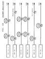
- FIG. 4A illustrates an example in which the winding-end expected time is calculated for the winding units 2 with unit Nos. 1 to 6.
- the arrow extending horizontally from the unit No. indicates time.
- a time denoted with reference numeral T1 or T2 below "fully-wound" written above the arrow indicates the winding-end expected time.
- the time denoted with the reference numeral T1 is the first winding-end expected time
- the time denoted with the reference numeral T2 is the second winding-end expected time.
- the illustrated state is a state after the discharge of the package 45 and before the supply of the bobbin 48, only the second winding-end expected time is illustrated.
- the machine control device 30 calculates the winding efficiency and the winding-end expected time in the above manner.
- the winding efficiency and the winding-end expected time of only the relevant winding unit 2 may be updated, or the winding efficiency and the winding-end expected time of all the winding units 2 may be updated.
- the machine control device 30 immediately stops the winding of the package 45, and instructs the operator to perform maintenance.
- the instruction for maintenance may not be made immediately and may be made after the package 45 currently being wound is fully wound.
- the machine control device 30 determines whether or not a difference between the produced quantity and the expected production quantity (hereinafter referred to as a remaining package quantity) is equal to or less than a predetermined value (step S105). If the remaining package quantity is greater than the predetermined value, the machine control device 30 supplies a new bobbin 48 to the winding unit 2 from which the package 45 has been discharged, and again returns to the process of step S101 to continue the winding of the package 45.
- a remaining package quantity a difference between the produced quantity and the expected production quantity
- the unit selection mode is a mode in which the winding efficiency of the entire fine spinning machine 1 is improved by selecting the winding unit 2 to perform the winding (determining whether or not to supply a new bobbin 48) in accordance with the winding efficiency and the winding-end expected time.
- any value can be specified for the "predetermined value” in the determination of step S105.
- variation in the winding efficiency of the winding unit 2 is large, the winding efficiency of the entire fine spinning machine 1 can be improved if the mode is shifted to the unit selection mode at an early stage, and thus the "predetermined value" may be set according to the variation in the winding efficiency.
- the machine control device 30 selects the winding unit 2 to which a new bobbin 48 is to be supplied (step S106). This selection is carried out in accordance with the remaining package quantity and the winding-end expected time of each of the winding units 2.
- the machine control device 30 of the present embodiment selects the winding unit 2 to which a new bobbin 48 is to be supplied in accordance with the first winding-end expected time and the second winding-end expected time. Specifically, if the remaining package quantity is nine in the example of FIG. 4A , since the winding of five packages 45 has already started, another four packages 45 is required to be produced. Thus, the machine control device 30 selects four winding units 2 in the order the second winding-end expected time is reached earlier. Accordingly, the winding units 2 with the unit Nos. 1, 3, 4, and 6 are selected. In this manner, the winding unit 2 to be supplied with a new bobbin 48 can be determined.
- the machine control device 30 controls such that a new bobbin 48 is supplied to the winding unit 2 selected in step S106 to continue the production of the package 45 (step S107). Meanwhile, the machine control device 30 determines whether or not the remaining package quantity is equal to or less than the number of winding units 2 performing winding (step S108).
- the machine control device 30 shifts to the lot-change mode, and stops the supply of a new bobbin 48 (step S109).
- the machine control device 30 controls such that the winding is performed in the winding unit 2, to which the bobbin 48 has already been supplied, to produce the packages 45 (step S110).
- the packages 45 of the expected production quantity are thereby produced.
- the present embodiment differs from the prior art in predicting the timing at which the winding is completed and determining whether or not to supply the bobbin 48 in accordance with the prediction. Therefore, in the present embodiment, as illustrated in Fig. 4A , the control which has not been possible in the prior art is carried out, e.g., a new bobbin 48 is supplied to the winding units 2 with the unit Nos. 1, 3, and 4 after the winding units 2 with the unit Nos. 2 and 5 complete the winding and start to be under standby.
- the fine spinning machine 1 of the present embodiment includes a plurality of the winding units 2 and the machine control device 30.
- Each of the plurality of the winding units 2 is adapted to wind the package 45.
- the machine control device 30 controls the plurality of the winding units 2.
- the machine control device 30 performs a control to calculate a winding-end expected time of the package 45 in each of the winding units 2.
- the machine control device 30 stores the produced quantity indicating the quantity of the packages 45 of which the winding has been completed. When a difference between the produced quantity and the expected production quantity becomes equal to or less than a predetermined value, the machine control device 30 determines whether or not to supply a new bobbin 48 to the winding units 2 in accordance with the winding-end expected time.
- the machine control device 30 calculates the first winding-end expected time and the second winding-end expected time.
- the first winding-end expected time is an expected time of completion of winding of the package 45 currently being wound in each of the winding units 2.
- the second winding-end expected time is an expected time of completion of winding of an additional package 45 if each of the winding units 2 winds the additional package 45.
- the machine control device 30 calculates the winding-end expected time in accordance with the winding efficiency of each of the winding units 2 within a predetermined period of time.
- the timing to shift to the unit selection mode is arbitrary. If shifted to the unit selection mode at an early stage, a third winding-end expected time may be obtained as illustrated in FIG. 5 .
- the winding unit 2 (unit No. 4) to which the new bobbin 48 is not supplied, the winding units 2 (unit Nos. 2, 3, 5) to which a new bobbin 48 is supplied only once, and the winding units 2 (unit Nos. 1, 6) to which a new bobbin 48 is supplied only twice may be generated.
- the doffing cart 4 is not essential and may be omitted.
- the example has been described in which the calculation of the winding efficiency and the winding-end expected time is performed in advance in the normal mode, but such calculation may be carried out after the shift to the unit selection mode.
- the winding efficiency and the winding-end expected time may be calculated and updated each time the package 45 becomes fully wound in a certain winding unit 2.
- the winding unit 2 under standby may be newly operated.
- the winding unit 2 that performs the winding in the unit selection mode may be changed according an input to the input section 32 made by the operator.
- An application range of the present invention is not limited to the fine spinning machine, and may be applied to other yarn winding machines (automatic winder, open end fine spinning machine, and the like) as long as such yarn winding machines have a configuration of discharging and supplying the bobbin.
Landscapes
- Engineering & Computer Science (AREA)
- Quality & Reliability (AREA)
- Spinning Or Twisting Of Yarns (AREA)
- Replacing, Conveying, And Pick-Finding For Filamentary Materials (AREA)
Abstract
Description
- The present invention relates to a yarn winding machine adapted to wind a package in each of a plurality of winding units.
- Conventionally, there is known a yarn winding machine including a doffing device adapted to discharge a fully-wound package and the like. Japanese Unexamined Patent Publication No.
8-109527 63-92577 2011-162351 -
Patent Document 1 discloses a control to efficiently move the doffing device (doffing cart). In the yarn winding machine ofPatent Document 1, a timing at which a package becomes fully wound in each winding unit (spinning machine) is predicted, and in accordance with predicted information, for example, the doffing device travels to the winding unit in which the package is immediately before a fully-wound state. Thus, a time during which each winding unit waits for the doffing device can be reduced, and a winding efficiency of the yarn winding machine can be improved. -
Patent Document 2 discloses a yarn winding machine adapted to prevent a large number of packages which are partially wound (partially-wound packages) from remaining upon change of lots. In the yarn winding machine ofPatent Document 2, a yarn quantity for one lot and a necessary remaining yarn quantity are obtained, and only a number of the winding units comparable to the remaining yarn quantity is operated. Furthermore,Patent Document 2 describes that a time required for obtaining one fully-wound package differs depending on the number of times of yarn breakages and other troubles. -
Patent Document 3 discloses a control to prevent supplying of a new bobbin to the winding unit after receiving a lot-change signal. - As described in
Patent Document 2, a winding efficiency is known to differ among the winding units. However,Patent Document 1 merely discloses the control for the travelling of the doffing cart, and does not mention about a control that takes into consideration the winding efficiency of the winding unit.Patent Documents - Thus, the conventional yarn winding machine still requires improvement in the winding efficiency of the entire yarn winding machine.
- It is an object of the present invention to provide a yarn winding machine adapted to efficiently produce packages using the fact that a winding efficiency differs among winding units.
- This object is achieved by a yarn winding machine according to
claim 1. - According to a first aspect of the present invention, a yarn winding machine includes a plurality of winding units and a control section. Each of the winding units is adapted to wind a package. The control section is adapted to control the plurality of the winding units. The control section is adapted to perform a control to calculate a winding-end expected time of the package in each of the winding units. The control section is also adapted to perform a control to store a produced quantity indicating a quantity of the package of which winding has been completed, and when a difference between the produced quantity and an expected production quantity is equal to or less than a predetermined value, to determine whether or not to supply a new bobbin to the winding units in accordance with the winding-end expected time.
- Thus, how many packages are to be wound in which winding unit can be determined in accordance with the winding-end expected time, and the winding efficiency of the entire yarn winding machine can be improved.
- In the yarn winding machine described above, the control section is adapted to calculate a first winding-end expected time and a second winding-end expected time. The first winding-end expected time is an expected time of completion of winding of the package currently being wound in each of the winding units. The second winding-end expected time is an expected time of completion of winding of an additional package if each of the winding units winds the additional package.
- Thus, how many packages are to be wound in which winding unit can be rationally determined in accordance with a specific time of completion of winding of the package, and the winding efficiency of the entire yarn winding machine can be further improved.
- In the yarn winding machine described above, the control section preferably calculates the winding-end expected time in accordance with a winding efficiency of each of the winding units within a predetermined period of time.
- Thus, a highly appropriate winding-end expected time can be obtained, and the winding efficiency of the entire yarn winding machine can be further improved.
- In the yarn winding machine described above, when each of the winding units completes winding of the package, the control section preferably calculates the winding-end expected time of at least such a winding unit.
- Thus, the winding-end expected time can be updated in accordance with the most recent information, and a highly appropriate winding-end expected time can be calculated.
- The yarn winding machine described above further preferably includes a doffing device adapted to perform a doffing operation to the plurality of the winding units to discharge the package of which the winding has been completed, and to perform a bobbin setting operation to the plurality of the winding units to supply the bobbin.
- Thus, in the yarn winding machine including the doffing device, the efficiency of the entire yarn winding machine can be improved.
- In the yarn winding machine described above, a priority order of the plurality of the winding units is preferably set in accordance with the winding-end expected time of each of the winding units, and the doffing device is preferably controlled to supply the bobbin to the winding units according to the priority order.
- Thus, the bobbin can be supplied in order to the winding units with early winding-end expected time, and the efficiency of the entire yarn winding machine can be further improved.
- In the yarn winding machine described above, when a number of the winding units performing the winding becomes the predetermined number or less, the control section preferably prohibits the doffing device from supplying the bobbin after discharging the package of which winding has been completed from each of the winding units.
- Thus, after reaching the expected production quantity, the winding can be automatically interrupted.
- In the yarn winding machine described above, the control section preferably calculates a winding efficiency of each of the winding units within a predetermined period of time, and prevents the winding unit of which the winding efficiency is a predetermined efficiency or lower from performing the winding of the package.
- By interrupting the winding in the winding unit of which the winding efficiency is low, maintenance and the like can be carried out in such a winding unit.
- The yarn winding machine described above further preferably includes an input section adapted to input the expected production quantity.
- Thus, an operator can easily correct the expected production quantity according to change in production plan and the like.
- According to a second aspect of the present invention, a yarn winding machine includes a plurality of winding units and a control section. Each of the winding units is adapted to wind a package. The control section is adapted to control the plurality of the winding units. The control section is adapted to store a produced quantity indicating a quantity of the package of which winding has been completed, and when a difference between the produced quantity and an expected production quantity becomes equal to or less than a predetermined value, to prevent the winding unit of which has been determined to have a low winding efficiency from winding the new package.
- By prohibiting the winding of the package in the winding unit of which the winding efficiency is low, the package can be preferentially wound in the winding unit of which the winding efficiency is high, and the winding efficiency of the entire yarn winding machine can be improved.
- According to a third aspect of the present invention, a yarn winding machine includes a plurality of winding units, a doffing device, and a control section. Each of the winding units is adapted to wind a package. The doffing device is adapted to perform a doffing operation to the plurality of the winding units to discharge the package of which the winding has been completed, and to perform a bobbin setting operation to the plurality of the winding units to supply the bobbin around which a yarn is to be wound. The control section is adapted to control the plurality of the winding units and the doffing device. Under a state in which at least one of the plurality of the winding units has completed winding of the package and is under standby, the control section is adapted to control the doffing device to supply the bobbin to a different one of the winding units in order to wind a remaining package that is to satisfy an expected production quantity.
- Thus, the package can be preferentially wound in a desired winding unit, and the winding efficiency of the entire yarn winding machine can be improved.
- In the yarn winding machine described above, each of the winding units includes a draft device, a spinning device, and a winding device. The draft device is adapted to draft a fiber bundle. The spinning device is adapted to spin the fiber bundle, drafted by the draft device, by a whirling airflow to produce a spun yarn. The winding device is adapted to wind the spun yarn produced by the spinning device into a package.
- Thus, since an air jet spinning machine can perform spinning at a high-speed, the winding efficiency of the entire yarn winding machine can be further improved.
-
-
FIG. 1 is a front view illustrating an overall structure of a fine spinning machine according to one embodiment of the present invention; -
FIG. 2 is a longitudinal cross-sectional view of the fine spinning machine; -
FIG. 3 is a flowchart illustrating a control in an expected production quantity mode; -
FIGS. 4A and4B are views comparing a winding efficiency of the present embodiment and a winding efficiency of the prior art; and -
FIG. 5 is a view describing a winding-end expected time according to an alternative embodiment. - A fine spinning machine (yarn winding machine) according to one embodiment of the present invention will be described with reference to the drawings. "Upstream" and "downstream" respectively refer to upstream and downstream in a travelling direction of a yarn during spinning.
- A
fine spinning machine 1 as a yarn winding machine illustrated inFIG. 1 includes a plurality of windingunits 2 arranged in line, ayarn joining cart 3, a doffing cart (doffing device) 4, ablower box 93, and amotor box 5. - The
motor box 5 includes a machine control device (control section) 30. Themachine control device 30 controls a plurality of the windingunits 2. Themachine control device 30 includes a color liquid crystal monitor 31 and aninput section 32. When an operator performs an appropriate operation, the color liquid crystal monitor 31 displays information related to an operation status and/or a yarn quality of each of the windingunits 2. Theinput section 32 includes a plurality of input keys. Theinput section 32 is used such that the operator can select information to be displayed on the colorliquid crystal monitor 31. Theinput section 32 accepts transmission of an appropriate instruction to each of the windingunits 2, setting of various types of conditions, and the like. - As illustrated in
FIG. 1 , each windingunit 2 includes adraft device 7, a spinning device 9, ayarn accumulating device 12, and a windingdevice 13 in this order from upstream to downstream. Thedraft device 7 is arranged in proximity to an upper end of aframe 6 of thefine spinning machine 1. Afiber bundle 8 fed from thedraft device 7 is spun by the spinning device 9. A spunyarn 10 fed from the spinning device 9 passes through ayarn clearer 49, to be described later, and further passes through theyarn accumulating device 12. The spunyarn 10 is wound around abobbin 48 by the windingdevice 13, and apackage 45 is formed. - The
draft device 7 drafts asliver 15 to obtain thefiber bundle 8. As illustrated inFIG. 2 , thedraft device 7 includes four roller pairs, i.e., aback roller pair 16, athird roller pair 17, amiddle roller pair 19 provided withapron belts 18, and afront roller pair 20. - Although a detailed structure of the spinning device 9 is not illustrated, the spinning device 9 of the present embodiment uses a whirling airflow to apply twists to the
fiber bundle 8 to produce the spunyarn 10. - The
yarn accumulating device 12 is arranged downstream of the spinning device 9. Theyarn accumulating device 12 has a function of applying a predetermined tension on the spunyarn 10 to pull out the spunyarn 10 from the spinning device 9, a function of accumulating the spunyarn 10 fed from the spinning device 9 during a yarn joining operation by theyarn joining cart 3 to prevent slackening of the spunyarn 10, and a function of adjusting the yarn tension such that a fluctuation of the yarn tension at the downstream of theyarn accumulating device 12 is not transmitted towards the spinning device 9. As illustrated inFIG. 2 , theyarn accumulating device 12 includes ayarn accumulating roller 21, ayarn engagement member 22, anupstream guide 23, and anelectric motor 25. - The
yarn engagement member 22 can be engaged with the spunyarn 10, and integrally rotates with theyarn accumulating roller 21 while being engaged with the spunyarn 10 to guide the spunyarn 10 to an outer peripheral surface of theyarn accumulating roller 21. - The
yarn accumulating roller 21 winds the spunyarn 10 around the outer peripheral surface thereof to accumulate the spunyarn 10. Theyarn accumulating roller 21 is rotatably driven at a constant rotation speed by theelectric motor 25. - The
yarn engagement member 22 is supported in a relatively rotatable manner with respect to theyarn accumulating roller 21. A torque (resistance torque) against a relative rotation with respect to theyarn accumulating roller 21 is applied to theyarn engagement member 22 by a torque generating means including a magnetic means, for example. Thus, when theyarn engagement member 22 is engaged with the spunyarn 10, if a tension applied to the spunyarn 10 is greater than the resistance toque, theyarn engagement member 22 rotates independently from theyarn accumulating roller 21 and the spunyarn 10 is unwound from theyarn accumulating roller 21. If the tension applied to the spunyarn 10 is less than the resistance torque, theyarn engagement member 22 integrally rotates with theyarn accumulating roller 21 and the spunyarn 10 is wound around theyarn accumulating roller 21. - The
upstream guide 23 is arranged slightly upstream of theyarn accumulating roller 21. Theupstream guide 23 appropriately guides the spunyarn 10 with respect to the outer peripheral surface of theyarn accumulating roller 21. Theupstream guide 23 prevents the twist of the spunyarn 10 propagating from the spinning device 9 from being transmitted downstream of theupstream guide 23. - The
yarn clearer 49 is arranged on a front side of theframe 6 of thefine spinning machine 1 at a position between the spinning device 9 and theyarn accumulating device 12. The spunyarn 10 from the spinning device 9 passes through theyarn clearer 49 before being wound by theyarn accumulating device 12. Theyarn clearer 49 monitors a thickness of the travelling spunyarn 10. When a yarn defect of the spunyarn 10 is detected, theyarn clearer 49 transmits a yarn defect detection signal to a unit controller (not illustrated). In addition to thickness abnormality of the spunyarn 10, theyarn clearer 49 may detect presence or absence of foreign substances contained in the spunyarn 10. - When receiving the yarn defect detection signal from the
yarn clearer 49, the unit controller stops the spinning by the spinning device 9 to cut the spunyarn 10, and also stops thedraft device 7 and the like. The unit controller also transmits a control signal to theyarn joining cart 3, and theyarn joining cart 3 travels to front of the relevant windingunit 2. Thereafter, the unit controller drives the spinning device 9 and the like again, theyarn joining cart 3 performs a yarn joining operation, and winding is resumed. - As illustrated in
FIG. 1 andFIG. 2 , theyarn joining cart 3 includes a splicer (yarn joining device) 43, asuction pipe 44, asuction mouth 46, andtravel wheels 42. When yarn breakage or yarn cut occurs in a windingunit 2, theyarn joining cart 3 drives thetravel wheels 42 and travels on a travellingrail 41. The travellingrail 41 is fixed to theframe 6. Theyarn joining cart 3 stops in front of the windingunit 2 in which the yarn breakage or the yarn cut occurred, and performs the yarn joining operation. - The
suction pipe 44 can swing vertically with an axis as a center. Thesuction pipe 44 sucks and catches a yarn end (upper yarn) from the spinning device 9, and guides the yarn end to thesplicer 43. Thesuction mouth 46 can swing vertically with an axis as a center. Thesuction mouth 46 sucks and catches a yarn end (lower yarn) from thepackage 45 supported by the windingdevice 13, and guides the yarn end to thesplicer 43. Although a description on a detailed configuration of thesplicer 43 will be omitted, the upper yarn and the lower yarn are joined by applying twists to the yarn ends by the whirling airflow. - The winding
device 13 includes acradle 70. Thecradle 70 includes a supportingshaft 73, acradle arm 71, and bobbin holders. Thecradle arm 71 can swing with the supportingshaft 73 as the center. The bobbin holders can hold both ends of thebobbin 48. - The winding
device 13 includes a windingdrum 74, and atraverse guide 76 capable of being engaged with the spunyarn 10. The windingdrum 74 is driven while making contact with an outer peripheral surface of thebobbin 48 or an outer peripheral surface of thepackage 45. The windingdevice 13 drives the windingdrum 74 with an electric motor (not illustrated) to rotate thepackage 45 making contact with the windingdrum 74 while reciprocating thetraverse guide 76 with a driving means (not illustrated), and the spunyarn 10 is wound while being traversed. - As illustrated in
FIG. 1 andFIG. 2 , the doffingcart 4 includes abobbin setting device 60. Thebobbin setting device 60 performs a bobbin setting operation of supplying thebobbin 48 to thecradle 70 to prepare for the winding of the spunyarn 10, and a doffing operation of detaching the fully-wound package (the package of which the winding has been completed) 45 from thecradle 70.Travel wheels 92 are provided in a lower portion of the doffingcart 4. When receiving an instruction to perform the bobbin setting operation and/or the doffing operation with respect to a certain windingunit 2, the doffingcart 4 travels along a travellingpath 91 to the relevant windingunit 2. The travellingpath 91 is formed on theframe 6. The doffingcart 4 stops in front of the instructed windingunit 2 and performs the bobbin setting operation or the doffing operation (or the both operations). - The
bobbin setting device 60 includes abobbin supply section 50 and asuction pipe 88 for performing the bobbin setting operation. - The
suction pipe 88 is capable of swinging, and extending and contracting. Thesuction pipe 88 sucks and catches the spunyarn 10 from the spinning device 9, and guides the caught spunyarn 10 to the windingdevice 13. - The
bobbin supply section 50 can swing with aswing shaft 111 as a center, and can grip thebobbin 48 with a bobbin gripping section 52. The doffingcart 4 swings thebobbin supply section 50 with the grippedbobbin 48, and supplies thebobbin 48 to thecradle 70. - The
bobbin setting device 60 includes a transportingsection 61 illustrated inFIG. 2 for performing the doffing operation. The transportingsection 61 guides the fully-wound package 45 discharged from thecradle 70 to a receiving section 82 via an inclined section 81. The transportingsection 61 includes a guidingplate 69 and abobbin guiding cylinder 62. - The guiding
plate 69 guides thepackage 45 while making contact with the outer peripheral surface of the fully-wound package 45 received from thecradle 70. - The
bobbin guiding cylinder 62 can vertically swing the guidingplate 69 by extending and contracting the cylinder. The transportingsection 61 can adjust a position of the guidingplate 69 when guiding thepackage 45, and stop rotation of thepackage 45 that continues to rotate due to inertia even after the winding of thepackage 45 has been completed. - Next, a description will be made on a control for producing the
packages 45 in accordance with the winding efficiency of the windingunit 2. - In the present embodiment, a continuous production mode and an expected production quantity mode can be set. The continuous production mode is a mode in which the
packages 45 are continuously produced until a predetermined instruction is given. The expected production quantity mode is a mode in which thepackages 45 of a quantity specified in advance are produced. In the expected production quantity mode, the mode shifts to a normal mode, a unit selection mode, and a lot-change mode according to a progress status of the winding. In the following description, expressions such as a quantity of thepackage 45, a total quantity, an expected production quantity, and the like are concepts including the number, a weight, a total length, and the like of thepackage 45. - The operator operates the
input section 32 to input or change the expected production quantity in the expected production quantity mode. - As illustrated in
FIG. 3 , the normal mode is set first. In the normal mode, themachine control device 30 controls each of the windingunits 2 to perform the winding operation of the package 45 (step S101). - When the
package 45 is fully wound in a certain windingunit 2, themachine control device 30 controls the doffingcart 4 to discharge therelevant package 45 from the winding unit 2 (step S102). Thereafter, themachine control device 30 updates and stores the produced quantity (step S103). The produced quantity is the total amount ofpackages 45 produced after the start of the present lot. - Next, the
machine control device 30 calculates the winding efficiency of the winding unit 2 (step S104). The winding efficiency is the quantity of thepackages 45 that can be produced per unit time, for example. The winding efficiency is calculated in accordance with the quantity of thepackages 45 produced in each of the windingunits 2 in the predetermined period of time. In order to calculate an accurate winding efficiency, the winding efficiency is calculated in a period of time excluding the time in which the winding is stopped. A specific example of the time in which the winding is stopped includes a time during maintenance, and a time during standby in the unit selection mode and the lot-change mode. - The
machine control device 30 calculates the winding efficiency and also calculates the winding-end expected time (step S104). - The winding-end expected time is an expected time at which the winding
unit 2 completes the winding of thepackage 45. In the present embodiment, themachine control device 30 calculates a first winding-end expected time and a second winding-end expected time. The first winding-end expected time is a time of completion of winding of thepackage 45 currently being wound. The second winding-end expected time is a time of completion of winding of thepackage 45 when anadditional bobbin 48 is supplied. - For calculation of the first winding-end expected time, the progress status of the winding of the
package 45 that is currently being wound, the quantity of the fully-wound packages 45, and the calculated winding efficiency are used. For calculation of the second winding-end expected time, the quantity of the fully-wound packages 45 and the winding efficiency are used. -
FIG. 4A illustrates an example in which the winding-end expected time is calculated for the windingunits 2 with unit Nos. 1 to 6. The arrow extending horizontally from the unit No. indicates time. A time denoted with reference numeral T1 or T2 below "fully-wound" written above the arrow indicates the winding-end expected time. Specifically, the time denoted with the reference numeral T1 is the first winding-end expected time, and the time denoted with the reference numeral T2 is the second winding-end expected time. With respect to the unit No. 6, since the illustrated state is a state after the discharge of thepackage 45 and before the supply of thebobbin 48, only the second winding-end expected time is illustrated. Themachine control device 30 calculates the winding efficiency and the winding-end expected time in the above manner. - When the fully-
wound package 45 is discharged from a certain windingunit 2, the winding efficiency and the winding-end expected time of only the relevant windingunit 2 may be updated, or the winding efficiency and the winding-end expected time of all the windingunits 2 may be updated. - As a result of calculating the winding efficiency, for the winding
unit 2 of which the winding efficiency is significantly low, themachine control device 30 immediately stops the winding of thepackage 45, and instructs the operator to perform maintenance. The instruction for maintenance may not be made immediately and may be made after thepackage 45 currently being wound is fully wound. - Next, the
machine control device 30 determines whether or not a difference between the produced quantity and the expected production quantity (hereinafter referred to as a remaining package quantity) is equal to or less than a predetermined value (step S105). If the remaining package quantity is greater than the predetermined value, themachine control device 30 supplies anew bobbin 48 to the windingunit 2 from which thepackage 45 has been discharged, and again returns to the process of step S101 to continue the winding of thepackage 45. - If the remaining package quantity is equal to or less than the predetermined value, the
machine control device 30 shifts from the normal mode to the unit selection mode. The unit selection mode is a mode in which the winding efficiency of the entirefine spinning machine 1 is improved by selecting the windingunit 2 to perform the winding (determining whether or not to supply a new bobbin 48) in accordance with the winding efficiency and the winding-end expected time. - Any value can be specified for the "predetermined value" in the determination of step S105. When variation in the winding efficiency of the winding
unit 2 is large, the winding efficiency of the entirefine spinning machine 1 can be improved if the mode is shifted to the unit selection mode at an early stage, and thus the "predetermined value" may be set according to the variation in the winding efficiency. - After being shifted to the unit selection mode, the
machine control device 30 selects the windingunit 2 to which anew bobbin 48 is to be supplied (step S106). This selection is carried out in accordance with the remaining package quantity and the winding-end expected time of each of the windingunits 2. - The
machine control device 30 of the present embodiment selects the windingunit 2 to which anew bobbin 48 is to be supplied in accordance with the first winding-end expected time and the second winding-end expected time. Specifically, if the remaining package quantity is nine in the example ofFIG. 4A , since the winding of fivepackages 45 has already started, another fourpackages 45 is required to be produced. Thus, themachine control device 30 selects four windingunits 2 in the order the second winding-end expected time is reached earlier. Accordingly, the windingunits 2 with the unit Nos. 1, 3, 4, and 6 are selected. In this manner, the windingunit 2 to be supplied with anew bobbin 48 can be determined. - If the control based on the winding efficiency of the winding
units 2 is not carried out, as is done in the prior art, anew bobbin 48 is supplied when thepackage 45 is fully wound and the expected production quantity is not yet reached. Therefore, as illustrated inFIG. 4B , thenew bobbin 48 is supplied even after thepackage 45 is fully wound in the unit No. 2 and 5 of which the winding efficiency is low. As a result, the timing of reaching the expected production quantity becomes later than that in the present embodiment. In other words, by performing the control of the present embodiment, the winding efficiency of the entirefine spinning machine 1 can be improved as compared to the prior art. - Next, the
machine control device 30 controls such that anew bobbin 48 is supplied to the windingunit 2 selected in step S106 to continue the production of the package 45 (step S107). Meanwhile, themachine control device 30 determines whether or not the remaining package quantity is equal to or less than the number of windingunits 2 performing winding (step S108). - If the remaining package quantity is greater than the number of winding
units 2 performing winding, anew bobbin 48 is required to be supplied. If the remaining package quantity is equal to or less than the number of windingunits 2 performing winding, the expected production quantity can be reached without supplying anew bobbin 48. Therefore, in this case, themachine control device 30 shifts to the lot-change mode, and stops the supply of a new bobbin 48 (step S109). - Thereafter, the
machine control device 30 controls such that the winding is performed in the windingunit 2, to which thebobbin 48 has already been supplied, to produce the packages 45 (step S110). Thepackages 45 of the expected production quantity are thereby produced. - Therefore, the present embodiment differs from the prior art in predicting the timing at which the winding is completed and determining whether or not to supply the
bobbin 48 in accordance with the prediction. Therefore, in the present embodiment, as illustrated inFig. 4A , the control which has not been possible in the prior art is carried out, e.g., anew bobbin 48 is supplied to the windingunits 2 with the unit Nos. 1, 3, and 4 after the windingunits 2 with the unit Nos. 2 and 5 complete the winding and start to be under standby. - As described above, the
fine spinning machine 1 of the present embodiment includes a plurality of the windingunits 2 and themachine control device 30. Each of the plurality of the windingunits 2 is adapted to wind thepackage 45. Themachine control device 30 controls the plurality of the windingunits 2. Themachine control device 30 performs a control to calculate a winding-end expected time of thepackage 45 in each of the windingunits 2. Themachine control device 30 stores the produced quantity indicating the quantity of thepackages 45 of which the winding has been completed. When a difference between the produced quantity and the expected production quantity becomes equal to or less than a predetermined value, themachine control device 30 determines whether or not to supply anew bobbin 48 to the windingunits 2 in accordance with the winding-end expected time. - Thus, how
many packages 45 is to be wound in which windingunit 2 can be determined in accordance with the winding-end expected time, and the winding efficiency of the entirefine spinning machine 1 can be improved. - In the
fine spinning machine 1 of the present embodiment, themachine control device 30 calculates the first winding-end expected time and the second winding-end expected time. The first winding-end expected time is an expected time of completion of winding of thepackage 45 currently being wound in each of the windingunits 2. The second winding-end expected time is an expected time of completion of winding of anadditional package 45 if each of the windingunits 2 winds theadditional package 45. - Thus, how
many packages 45 is to be wound in which windingunit 2 can be rationally determined in accordance with the specific time of completion of winding of thepackage 45, and the winding efficiency of the entirefine spinning machine 1 can be further improved. - In the
fine spinning machine 1 of the present embodiment, themachine control device 30 calculates the winding-end expected time in accordance with the winding efficiency of each of the windingunits 2 within a predetermined period of time. - Thus, the highly appropriate winding-end expected time is obtained, and the winding efficiency of the entire
fine spinning machine 1 can be further improved. - The preferable embodiments of the present invention have been described above, but the configuration described above can be modified as below, for example.
- As described above, the timing to shift to the unit selection mode is arbitrary. If shifted to the unit selection mode at an early stage, a third winding-end expected time may be obtained as illustrated in
FIG. 5 . In this case, the winding unit 2 (unit No. 4) to which thenew bobbin 48 is not supplied, the winding units 2 (unit Nos. 2, 3, 5) to which anew bobbin 48 is supplied only once, and the winding units 2 (unit Nos. 1, 6) to which anew bobbin 48 is supplied only twice may be generated. - If the
bobbin 48 can be supplied to any windingunit 2, the doffingcart 4 is not essential and may be omitted. - In the above description, the example has been described in which the calculation of the winding efficiency and the winding-end expected time is performed in advance in the normal mode, but such calculation may be carried out after the shift to the unit selection mode. After the shift to the unit selection mode, the winding efficiency and the winding-end expected time may be calculated and updated each time the
package 45 becomes fully wound in a certain windingunit 2. In this case, for example, when the winding efficiency of a certain windingunit 2 has decreased, the windingunit 2 under standby may be newly operated. - The winding
unit 2 that performs the winding in the unit selection mode may be changed according an input to theinput section 32 made by the operator. - An application range of the present invention is not limited to the fine spinning machine, and may be applied to other yarn winding machines (automatic winder, open end fine spinning machine, and the like) as long as such yarn winding machines have a configuration of discharging and supplying the bobbin.
Claims (12)
- A yarn winding machine (1) comprising:a plurality of winding units (2), each being adapted to wind a package (45); anda control section (30) adapted to control the plurality of the winding units (2), the control section (30) being adapted to calculate a winding-end expected time of the package (45) in each of the winding units (2), to store a produced quantity indicating a quantity of the packages (45) of which winding has been completed, and, when a difference between the produced quantity and an expected production quantity is equal to or less than a predetermined value, to determine whether or not to supply a new bobbin (48) to the winding units (2) in accordance with the winding-end expected time.
- The yarn winding machine (1) according to claim 1, wherein as the winding-end expected time, the control section (30) is adapted to calculate a first winding-end expected time, which is an expected time of completion of winding of the package (45) currently being wound in each of the winding units (2), and a second winding-end expected time, which is an expected time of completion of winding of an additional package (45) if each of the winding units (2) winds the additional package (45).
- The yarn winding machine (1) according to claim 1 or claim 2, wherein the control section (30) is adapted to calculate the winding-end expected time in accordance with a winding efficiency of each of the winding units (2) within a predetermined period of time.
- The yarn winding machine (1) according to any one of claim 1 through claim 3, wherein when each of the winding units (2) completes winding of the package (45), the control section (30) is adapted to calculate the winding-end expected time of at least such a winding unit (2).
- The yarn winding machine (1) according to any one of claim 1 through claim 4, further comprising a doffing device (4) adapted to perform a doffing operation to the plurality of the winding units (2) to discharge the package (45) of which the winding has been completed, and to perform a bobbin setting operation to the plurality of the winding units (2) to supply the bobbin (48).
- The yarn winding machine (1) according to claim 5, wherein the control section (30) is adapted to set a priority order of the plurality of the winding units (2) in accordance with the winding-end expected time of each of the winding units (2), and to control the doffing device (4) to supply the bobbin (48) to the winding units (2) according to the priority order.
- The yarn winding machine (1) according to claim 5 or claim 6, wherein when a number of the winding units (2) performing the winding becomes the predetermined number or less, the control section (30) is adapted to prohibit the doffing device (4) from supplying the bobbin (48) after discharging the package (45) of which winding has been completed from each of the winding units (2).
- The yarn winding machine (1) according to any one of claim 1 through claim 7, wherein the control section (30) is adapted to calculate a winding efficiency of each of the winding units (2) within a predetermined period of time, and to prevent the winding unit (2) of which the winding efficiency is a predetermined efficiency or lower from performing the winding.
- The yarn winding machine (1) according to any one of claim 1 through claim 8, further comprising an input section (32) adapted to input the expected production quantity.
- The yarn winding machine (1) according to any one of claim 1 through claim 9, wherein:the control section (30) is adapted to prevent the winding unit (2) of which has been determined to have a low winding efficiency from winding the new package (45), when a difference between the produced quantity and the expected production quantity becomes equal to or less than a predetermined value.
- A yarn winding machine (1) according to any one of claim 1 through claim 9, comprising:a doffing device (4) adapted to perform a doffing operation to the plurality of the winding units (2) to discharge the package (45) of which the winding has been completed, and to perform a bobbin setting operation to the plurality of the winding units (2) to supply the bobbin (48) around which a yarn (10) is to be wound;wherein under a state in which at least one of the plurality of the winding units (2) has completed winding of the package (45) and is under standby, the control section (3) is adapted to control the doffing device (4) to supply the bobbin (48) to a different one of the winding units (2) in order to wind a remaining package (45) that is to satisfy an expected production quantity.
- The yarn winding machine (1) according to any one of claim 1 through claim 11, wherein each of the winding units (2) includes:a draft device (7) adapted to draft a fiber bundle (15);a spinning device (9) adapted to spin the fiber bundle (15), drafted by the draft device (7), by a whirling airflow to produce a spun yarn (10); anda winding device (13) adapted to wind the spun yarn (10) produced by the spinning device (9) into a package (45).
Applications Claiming Priority (1)
| Application Number | Priority Date | Filing Date | Title |
|---|---|---|---|
| JP2013107188A JP2014227249A (en) | 2013-05-21 | 2013-05-21 | Yarn winder |
Publications (2)
| Publication Number | Publication Date |
|---|---|
| EP2805907A1 true EP2805907A1 (en) | 2014-11-26 |
| EP2805907B1 EP2805907B1 (en) | 2016-05-18 |
Family
ID=50389334
Family Applications (1)
| Application Number | Title | Priority Date | Filing Date |
|---|---|---|---|
| EP14162429.6A Not-in-force EP2805907B1 (en) | 2013-05-21 | 2014-03-28 | Yarn winding machine |
Country Status (3)
| Country | Link |
|---|---|
| EP (1) | EP2805907B1 (en) |
| JP (1) | JP2014227249A (en) |
| CN (1) | CN104176558B (en) |
Cited By (2)
| Publication number | Priority date | Publication date | Assignee | Title |
|---|---|---|---|---|
| EP3239084A1 (en) * | 2016-04-29 | 2017-11-01 | Rieter Ingolstadt GmbH | Textile machine and method for operating the same |
| EP3653553A1 (en) * | 2018-11-19 | 2020-05-20 | Murata Machinery, Ltd. | Production volume simulation apparatus and predicted production volume calculation method |
Families Citing this family (3)
| Publication number | Priority date | Publication date | Assignee | Title |
|---|---|---|---|---|
| JP2018090375A (en) * | 2016-12-02 | 2018-06-14 | 村田機械株式会社 | Automatic winder, and winding speed control method for automatic winder |
| JP2019119538A (en) * | 2017-12-28 | 2019-07-22 | 村田機械株式会社 | Spool machine |
| CN111924660B (en) * | 2020-07-08 | 2022-04-19 | 北自所(北京)科技发展有限公司 | Chemical fiber filament doffing method and system based on twin model and automatic doffing equipment |
Citations (6)
| Publication number | Priority date | Publication date | Assignee | Title |
|---|---|---|---|---|
| JPS6392577A (en) | 1986-10-06 | 1988-04-23 | Murata Mach Ltd | Yarn winding method in automatic winder |
| US4856723A (en) * | 1987-03-12 | 1989-08-15 | Murata Kikai Kabushiki Kaisha | Method and apparatus for changing bobbins in lot for an automatic winder |
| US5398878A (en) * | 1992-05-15 | 1995-03-21 | W. Schlafhorst Ag & Co. | Method and apparatus for producing a predetermined number of full yarn packages on an automatic winder |
| JPH08109527A (en) | 1994-10-04 | 1996-04-30 | Nisshinbo Ind Inc | Control of traveling of automatic doffing machine in fine spinning process |
| US5947405A (en) * | 1996-11-21 | 1999-09-07 | W. Schlafhorst Ag & Co. | Method for optimizing a batch change in an open-end spinning machine |
| JP2011162351A (en) | 2010-01-15 | 2011-08-25 | Murata Machinery Ltd | Doffing apparatus |
Family Cites Families (2)
| Publication number | Priority date | Publication date | Assignee | Title |
|---|---|---|---|---|
| JP2011144028A (en) * | 2010-01-15 | 2011-07-28 | Murata Machinery Ltd | Yarn winding machine and yarn guiding method |
| CN202687633U (en) * | 2012-07-03 | 2013-01-23 | 惠阳中核辉新化纤有限公司 | Control device of yarn winder |
-
2013
- 2013-05-21 JP JP2013107188A patent/JP2014227249A/en active Pending
-
2014
- 2014-03-28 EP EP14162429.6A patent/EP2805907B1/en not_active Not-in-force
- 2014-05-13 CN CN201410201133.5A patent/CN104176558B/en active Active
Patent Citations (6)
| Publication number | Priority date | Publication date | Assignee | Title |
|---|---|---|---|---|
| JPS6392577A (en) | 1986-10-06 | 1988-04-23 | Murata Mach Ltd | Yarn winding method in automatic winder |
| US4856723A (en) * | 1987-03-12 | 1989-08-15 | Murata Kikai Kabushiki Kaisha | Method and apparatus for changing bobbins in lot for an automatic winder |
| US5398878A (en) * | 1992-05-15 | 1995-03-21 | W. Schlafhorst Ag & Co. | Method and apparatus for producing a predetermined number of full yarn packages on an automatic winder |
| JPH08109527A (en) | 1994-10-04 | 1996-04-30 | Nisshinbo Ind Inc | Control of traveling of automatic doffing machine in fine spinning process |
| US5947405A (en) * | 1996-11-21 | 1999-09-07 | W. Schlafhorst Ag & Co. | Method for optimizing a batch change in an open-end spinning machine |
| JP2011162351A (en) | 2010-01-15 | 2011-08-25 | Murata Machinery Ltd | Doffing apparatus |
Cited By (3)
| Publication number | Priority date | Publication date | Assignee | Title |
|---|---|---|---|---|
| EP3239084A1 (en) * | 2016-04-29 | 2017-11-01 | Rieter Ingolstadt GmbH | Textile machine and method for operating the same |
| DE102016107994A1 (en) * | 2016-04-29 | 2017-11-02 | Rieter Ingolstadt Gmbh | Textile machine and method for operating the same |
| EP3653553A1 (en) * | 2018-11-19 | 2020-05-20 | Murata Machinery, Ltd. | Production volume simulation apparatus and predicted production volume calculation method |
Also Published As
| Publication number | Publication date |
|---|---|
| JP2014227249A (en) | 2014-12-08 |
| EP2805907B1 (en) | 2016-05-18 |
| CN104176558B (en) | 2018-02-06 |
| CN104176558A (en) | 2014-12-03 |
Similar Documents
| Publication | Publication Date | Title |
|---|---|---|
| JP6080153B2 (en) | Spinning machine and method for interrupting the production of yarn in a spinning machine | |
| EP2727870B1 (en) | Yarn winding machine and yarn winding method | |
| EP2169096A1 (en) | Spinning machine | |
| EP3269851B1 (en) | Spinning machine | |
| EP2805907B1 (en) | Yarn winding machine | |
| CN107614406B (en) | Yarn winding system, automatic winder, spinning frame, and yarn winding method | |
| EP3025995B1 (en) | Yarn winding machine | |
| EP2573217B1 (en) | Spinning unit, spinning machine and yarn processing method | |
| EP2690046B1 (en) | Yarn defect detecting device and winding device | |
| EP2298971B1 (en) | Spinning machine with yarn accumulating roller | |
| EP2966200B1 (en) | Spinning machine and spinning method | |
| EP2749517B1 (en) | Spinning machine | |
| EP2345611A2 (en) | Yarn winding machine and yarn guiding method | |
| CN102249120B (en) | Method for manufacturing spinning cops | |
| EP2977493B1 (en) | Spinning machine and spinning method | |
| EP3438334B1 (en) | Air spinning machine and display control method | |
| JP7463063B2 (en) | Method or device for influencing the winding state of a ring spinning cop | |
| JP2014009405A (en) | Spinning machine | |
| JP2017071865A (en) | Spinning machine | |
| CN115072478A (en) | Spinning machine | |
| EP3686330B1 (en) | Spinning method, spinning machine, and spinning program | |
| JP2024007744A (en) | Spinning machine, package forming method and package | |
| JP2021055227A (en) | Fiber waste generation amount calculation device, air spinning machine, and fiber waste generation amount output method | |
| CN115467054A (en) | Spinning machine | |
| WO2021153479A1 (en) | Thread winder |
Legal Events
| Date | Code | Title | Description |
|---|---|---|---|
| PUAI | Public reference made under article 153(3) epc to a published international application that has entered the european phase |
Free format text: ORIGINAL CODE: 0009012 |
|
| 17P | Request for examination filed |
Effective date: 20140328 |
|
| AK | Designated contracting states |
Kind code of ref document: A1 Designated state(s): AL AT BE BG CH CY CZ DE DK EE ES FI FR GB GR HR HU IE IS IT LI LT LU LV MC MK MT NL NO PL PT RO RS SE SI SK SM TR |
|
| AX | Request for extension of the european patent |
Extension state: BA ME |
|
| R17P | Request for examination filed (corrected) |
Effective date: 20150109 |
|
| RBV | Designated contracting states (corrected) |
Designated state(s): AL AT BE BG CH CY CZ DE DK EE ES FI FR GB GR HR HU IE IS IT LI LT LU LV MC MK MT NL NO PL PT RO RS SE SI SK SM TR |
|
| RIC1 | Information provided on ipc code assigned before grant |
Ipc: B65H 67/04 20060101ALI20150918BHEP Ipc: B65H 63/08 20060101ALI20150918BHEP Ipc: B65H 63/00 20060101ALI20150918BHEP Ipc: B65H 54/26 20060101AFI20150918BHEP |
|
| GRAP | Despatch of communication of intention to grant a patent |
Free format text: ORIGINAL CODE: EPIDOSNIGR1 |
|
| INTG | Intention to grant announced |
Effective date: 20151104 |
|
| GRAS | Grant fee paid |
Free format text: ORIGINAL CODE: EPIDOSNIGR3 |
|
| GRAA | (expected) grant |
Free format text: ORIGINAL CODE: 0009210 |
|
| AK | Designated contracting states |
Kind code of ref document: B1 Designated state(s): AL AT BE BG CH CY CZ DE DK EE ES FI FR GB GR HR HU IE IS IT LI LT LU LV MC MK MT NL NO PL PT RO RS SE SI SK SM TR |
|
| REG | Reference to a national code |
Ref country code: GB Ref legal event code: FG4D |
|
| REG | Reference to a national code |
Ref country code: CH Ref legal event code: NV Representative=s name: BOVARD AG, CH Ref country code: CH Ref legal event code: EP |
|
| REG | Reference to a national code |
Ref country code: IE Ref legal event code: FG4D Ref country code: AT Ref legal event code: REF Ref document number: 800261 Country of ref document: AT Kind code of ref document: T Effective date: 20160615 |
|
| REG | Reference to a national code |
Ref country code: DE Ref legal event code: R096 Ref document number: 602014001939 Country of ref document: DE |
|
| REG | Reference to a national code |
Ref country code: NL Ref legal event code: MP Effective date: 20160518 |
|
| REG | Reference to a national code |
Ref country code: LT Ref legal event code: MG4D |
|
| PG25 | Lapsed in a contracting state [announced via postgrant information from national office to epo] |
Ref country code: NO Free format text: LAPSE BECAUSE OF FAILURE TO SUBMIT A TRANSLATION OF THE DESCRIPTION OR TO PAY THE FEE WITHIN THE PRESCRIBED TIME-LIMIT Effective date: 20160818 Ref country code: LT Free format text: LAPSE BECAUSE OF FAILURE TO SUBMIT A TRANSLATION OF THE DESCRIPTION OR TO PAY THE FEE WITHIN THE PRESCRIBED TIME-LIMIT Effective date: 20160518 Ref country code: FI Free format text: LAPSE BECAUSE OF FAILURE TO SUBMIT A TRANSLATION OF THE DESCRIPTION OR TO PAY THE FEE WITHIN THE PRESCRIBED TIME-LIMIT Effective date: 20160518 Ref country code: NL Free format text: LAPSE BECAUSE OF FAILURE TO SUBMIT A TRANSLATION OF THE DESCRIPTION OR TO PAY THE FEE WITHIN THE PRESCRIBED TIME-LIMIT Effective date: 20160518 |
|
| REG | Reference to a national code |
Ref country code: AT Ref legal event code: MK05 Ref document number: 800261 Country of ref document: AT Kind code of ref document: T Effective date: 20160518 |
|
| PG25 | Lapsed in a contracting state [announced via postgrant information from national office to epo] |
Ref country code: SE Free format text: LAPSE BECAUSE OF FAILURE TO SUBMIT A TRANSLATION OF THE DESCRIPTION OR TO PAY THE FEE WITHIN THE PRESCRIBED TIME-LIMIT Effective date: 20160518 Ref country code: ES Free format text: LAPSE BECAUSE OF FAILURE TO SUBMIT A TRANSLATION OF THE DESCRIPTION OR TO PAY THE FEE WITHIN THE PRESCRIBED TIME-LIMIT Effective date: 20160518 Ref country code: RS Free format text: LAPSE BECAUSE OF FAILURE TO SUBMIT A TRANSLATION OF THE DESCRIPTION OR TO PAY THE FEE WITHIN THE PRESCRIBED TIME-LIMIT Effective date: 20160518 Ref country code: PT Free format text: LAPSE BECAUSE OF FAILURE TO SUBMIT A TRANSLATION OF THE DESCRIPTION OR TO PAY THE FEE WITHIN THE PRESCRIBED TIME-LIMIT Effective date: 20160919 Ref country code: GR Free format text: LAPSE BECAUSE OF FAILURE TO SUBMIT A TRANSLATION OF THE DESCRIPTION OR TO PAY THE FEE WITHIN THE PRESCRIBED TIME-LIMIT Effective date: 20160819 Ref country code: LV Free format text: LAPSE BECAUSE OF FAILURE TO SUBMIT A TRANSLATION OF THE DESCRIPTION OR TO PAY THE FEE WITHIN THE PRESCRIBED TIME-LIMIT Effective date: 20160518 Ref country code: HR Free format text: LAPSE BECAUSE OF FAILURE TO SUBMIT A TRANSLATION OF THE DESCRIPTION OR TO PAY THE FEE WITHIN THE PRESCRIBED TIME-LIMIT Effective date: 20160518 |
|
| PG25 | Lapsed in a contracting state [announced via postgrant information from national office to epo] |
Ref country code: IT Free format text: LAPSE BECAUSE OF FAILURE TO SUBMIT A TRANSLATION OF THE DESCRIPTION OR TO PAY THE FEE WITHIN THE PRESCRIBED TIME-LIMIT Effective date: 20160518 |
|
| PG25 | Lapsed in a contracting state [announced via postgrant information from national office to epo] |
Ref country code: EE Free format text: LAPSE BECAUSE OF FAILURE TO SUBMIT A TRANSLATION OF THE DESCRIPTION OR TO PAY THE FEE WITHIN THE PRESCRIBED TIME-LIMIT Effective date: 20160518 Ref country code: DK Free format text: LAPSE BECAUSE OF FAILURE TO SUBMIT A TRANSLATION OF THE DESCRIPTION OR TO PAY THE FEE WITHIN THE PRESCRIBED TIME-LIMIT Effective date: 20160518 Ref country code: SK Free format text: LAPSE BECAUSE OF FAILURE TO SUBMIT A TRANSLATION OF THE DESCRIPTION OR TO PAY THE FEE WITHIN THE PRESCRIBED TIME-LIMIT Effective date: 20160518 Ref country code: RO Free format text: LAPSE BECAUSE OF FAILURE TO SUBMIT A TRANSLATION OF THE DESCRIPTION OR TO PAY THE FEE WITHIN THE PRESCRIBED TIME-LIMIT Effective date: 20160518 |
|
| REG | Reference to a national code |
Ref country code: DE Ref legal event code: R097 Ref document number: 602014001939 Country of ref document: DE |
|
| PG25 | Lapsed in a contracting state [announced via postgrant information from national office to epo] |
Ref country code: SM Free format text: LAPSE BECAUSE OF FAILURE TO SUBMIT A TRANSLATION OF THE DESCRIPTION OR TO PAY THE FEE WITHIN THE PRESCRIBED TIME-LIMIT Effective date: 20160518 Ref country code: BE Free format text: LAPSE BECAUSE OF FAILURE TO SUBMIT A TRANSLATION OF THE DESCRIPTION OR TO PAY THE FEE WITHIN THE PRESCRIBED TIME-LIMIT Effective date: 20160518 Ref country code: PL Free format text: LAPSE BECAUSE OF FAILURE TO SUBMIT A TRANSLATION OF THE DESCRIPTION OR TO PAY THE FEE WITHIN THE PRESCRIBED TIME-LIMIT Effective date: 20160518 Ref country code: AT Free format text: LAPSE BECAUSE OF FAILURE TO SUBMIT A TRANSLATION OF THE DESCRIPTION OR TO PAY THE FEE WITHIN THE PRESCRIBED TIME-LIMIT Effective date: 20160518 |
|
| PLBE | No opposition filed within time limit |
Free format text: ORIGINAL CODE: 0009261 |
|
| STAA | Information on the status of an ep patent application or granted ep patent |
Free format text: STATUS: NO OPPOSITION FILED WITHIN TIME LIMIT |
|
| 26N | No opposition filed |
Effective date: 20170221 |
|
| PG25 | Lapsed in a contracting state [announced via postgrant information from national office to epo] |
Ref country code: SI Free format text: LAPSE BECAUSE OF FAILURE TO SUBMIT A TRANSLATION OF THE DESCRIPTION OR TO PAY THE FEE WITHIN THE PRESCRIBED TIME-LIMIT Effective date: 20160518 |
|
| PG25 | Lapsed in a contracting state [announced via postgrant information from national office to epo] |
Ref country code: MC Free format text: LAPSE BECAUSE OF FAILURE TO SUBMIT A TRANSLATION OF THE DESCRIPTION OR TO PAY THE FEE WITHIN THE PRESCRIBED TIME-LIMIT Effective date: 20160518 |
|
| REG | Reference to a national code |
Ref country code: IE Ref legal event code: MM4A |
|
| REG | Reference to a national code |
Ref country code: FR Ref legal event code: ST Effective date: 20171130 |
|
| PG25 | Lapsed in a contracting state [announced via postgrant information from national office to epo] |
Ref country code: LU Free format text: LAPSE BECAUSE OF NON-PAYMENT OF DUE FEES Effective date: 20170328 Ref country code: FR Free format text: LAPSE BECAUSE OF NON-PAYMENT OF DUE FEES Effective date: 20170331 |
|
| PG25 | Lapsed in a contracting state [announced via postgrant information from national office to epo] |
Ref country code: IE Free format text: LAPSE BECAUSE OF NON-PAYMENT OF DUE FEES Effective date: 20170328 |
|
| PG25 | Lapsed in a contracting state [announced via postgrant information from national office to epo] |
Ref country code: MT Free format text: LAPSE BECAUSE OF NON-PAYMENT OF DUE FEES Effective date: 20170328 |
|
| PG25 | Lapsed in a contracting state [announced via postgrant information from national office to epo] |
Ref country code: AL Free format text: LAPSE BECAUSE OF FAILURE TO SUBMIT A TRANSLATION OF THE DESCRIPTION OR TO PAY THE FEE WITHIN THE PRESCRIBED TIME-LIMIT Effective date: 20160518 |
|
| GBPC | Gb: european patent ceased through non-payment of renewal fee |
Effective date: 20180328 |
|
| PG25 | Lapsed in a contracting state [announced via postgrant information from national office to epo] |
Ref country code: GB Free format text: LAPSE BECAUSE OF NON-PAYMENT OF DUE FEES Effective date: 20180328 |
|
| PG25 | Lapsed in a contracting state [announced via postgrant information from national office to epo] |
Ref country code: HU Free format text: LAPSE BECAUSE OF FAILURE TO SUBMIT A TRANSLATION OF THE DESCRIPTION OR TO PAY THE FEE WITHIN THE PRESCRIBED TIME-LIMIT; INVALID AB INITIO Effective date: 20140328 |
|
| PG25 | Lapsed in a contracting state [announced via postgrant information from national office to epo] |
Ref country code: BG Free format text: LAPSE BECAUSE OF FAILURE TO SUBMIT A TRANSLATION OF THE DESCRIPTION OR TO PAY THE FEE WITHIN THE PRESCRIBED TIME-LIMIT Effective date: 20160518 |
|
| PG25 | Lapsed in a contracting state [announced via postgrant information from national office to epo] |
Ref country code: CY Free format text: LAPSE BECAUSE OF FAILURE TO SUBMIT A TRANSLATION OF THE DESCRIPTION OR TO PAY THE FEE WITHIN THE PRESCRIBED TIME-LIMIT Effective date: 20160518 |
|
| PG25 | Lapsed in a contracting state [announced via postgrant information from national office to epo] |
Ref country code: MK Free format text: LAPSE BECAUSE OF FAILURE TO SUBMIT A TRANSLATION OF THE DESCRIPTION OR TO PAY THE FEE WITHIN THE PRESCRIBED TIME-LIMIT Effective date: 20160518 |
|
| PG25 | Lapsed in a contracting state [announced via postgrant information from national office to epo] |
Ref country code: TR Free format text: LAPSE BECAUSE OF FAILURE TO SUBMIT A TRANSLATION OF THE DESCRIPTION OR TO PAY THE FEE WITHIN THE PRESCRIBED TIME-LIMIT Effective date: 20160518 |
|
| PGFP | Annual fee paid to national office [announced via postgrant information from national office to epo] |
Ref country code: DE Payment date: 20200320 Year of fee payment: 7 |
|
| PGFP | Annual fee paid to national office [announced via postgrant information from national office to epo] |
Ref country code: CH Payment date: 20200319 Year of fee payment: 7 Ref country code: CZ Payment date: 20200320 Year of fee payment: 7 |
|
| PG25 | Lapsed in a contracting state [announced via postgrant information from national office to epo] |
Ref country code: IS Free format text: LAPSE BECAUSE OF FAILURE TO SUBMIT A TRANSLATION OF THE DESCRIPTION OR TO PAY THE FEE WITHIN THE PRESCRIBED TIME-LIMIT Effective date: 20160918 |
|
| REG | Reference to a national code |
Ref country code: DE Ref legal event code: R119 Ref document number: 602014001939 Country of ref document: DE |
|
| PG25 | Lapsed in a contracting state [announced via postgrant information from national office to epo] |
Ref country code: CZ Free format text: LAPSE BECAUSE OF NON-PAYMENT OF DUE FEES Effective date: 20210328 |
|
| REG | Reference to a national code |
Ref country code: CH Ref legal event code: PL |
|
| PG25 | Lapsed in a contracting state [announced via postgrant information from national office to epo] |
Ref country code: LI Free format text: LAPSE BECAUSE OF NON-PAYMENT OF DUE FEES Effective date: 20210331 Ref country code: CH Free format text: LAPSE BECAUSE OF NON-PAYMENT OF DUE FEES Effective date: 20210331 Ref country code: DE Free format text: LAPSE BECAUSE OF NON-PAYMENT OF DUE FEES Effective date: 20211001 |