EP2805882A1 - Thermal pneumatic deicing system for an aircraft ram air heat exchanger - Google Patents
Thermal pneumatic deicing system for an aircraft ram air heat exchanger Download PDFInfo
- Publication number
- EP2805882A1 EP2805882A1 EP14169521.3A EP14169521A EP2805882A1 EP 2805882 A1 EP2805882 A1 EP 2805882A1 EP 14169521 A EP14169521 A EP 14169521A EP 2805882 A1 EP2805882 A1 EP 2805882A1
- Authority
- EP
- European Patent Office
- Prior art keywords
- heat exchanger
- ram air
- air heat
- duct
- electronics housing
- Prior art date
- Legal status (The legal status is an assumption and is not a legal conclusion. Google has not performed a legal analysis and makes no representation as to the accuracy of the status listed.)
- Granted
Links
Images

Classifications
-
- B—PERFORMING OPERATIONS; TRANSPORTING
- B64—AIRCRAFT; AVIATION; COSMONAUTICS
- B64D—EQUIPMENT FOR FITTING IN OR TO AIRCRAFT; FLIGHT SUITS; PARACHUTES; ARRANGEMENT OR MOUNTING OF POWER PLANTS OR PROPULSION TRANSMISSIONS IN AIRCRAFT
- B64D13/00—Arrangements or adaptations of air-treatment apparatus for aircraft crew or passengers, or freight space
-
- B—PERFORMING OPERATIONS; TRANSPORTING
- B64—AIRCRAFT; AVIATION; COSMONAUTICS
- B64D—EQUIPMENT FOR FITTING IN OR TO AIRCRAFT; FLIGHT SUITS; PARACHUTES; ARRANGEMENT OR MOUNTING OF POWER PLANTS OR PROPULSION TRANSMISSIONS IN AIRCRAFT
- B64D13/00—Arrangements or adaptations of air-treatment apparatus for aircraft crew or passengers, or freight space
- B64D13/06—Arrangements or adaptations of air-treatment apparatus for aircraft crew or passengers, or freight space the air being conditioned
- B64D2013/0603—Environmental Control Systems
- B64D2013/0618—Environmental Control Systems with arrangements for reducing or managing bleed air, using another air source, e.g. ram air
-
- B—PERFORMING OPERATIONS; TRANSPORTING
- B64—AIRCRAFT; AVIATION; COSMONAUTICS
- B64D—EQUIPMENT FOR FITTING IN OR TO AIRCRAFT; FLIGHT SUITS; PARACHUTES; ARRANGEMENT OR MOUNTING OF POWER PLANTS OR PROPULSION TRANSMISSIONS IN AIRCRAFT
- B64D13/00—Arrangements or adaptations of air-treatment apparatus for aircraft crew or passengers, or freight space
- B64D13/06—Arrangements or adaptations of air-treatment apparatus for aircraft crew or passengers, or freight space the air being conditioned
- B64D2013/0603—Environmental Control Systems
- B64D2013/0666—Environmental Control Systems with means for preventing icing within the ECS components
-
- Y—GENERAL TAGGING OF NEW TECHNOLOGICAL DEVELOPMENTS; GENERAL TAGGING OF CROSS-SECTIONAL TECHNOLOGIES SPANNING OVER SEVERAL SECTIONS OF THE IPC; TECHNICAL SUBJECTS COVERED BY FORMER USPC CROSS-REFERENCE ART COLLECTIONS [XRACs] AND DIGESTS
- Y02—TECHNOLOGIES OR APPLICATIONS FOR MITIGATION OR ADAPTATION AGAINST CLIMATE CHANGE
- Y02T—CLIMATE CHANGE MITIGATION TECHNOLOGIES RELATED TO TRANSPORTATION
- Y02T50/00—Aeronautics or air transport
- Y02T50/50—On board measures aiming to increase energy efficiency
Definitions
- Exemplary embodiments pertain to the art of aircraft systems and, more particularly, to a thermal pneumatic deicing system for an aircraft RAM air heat exchanger.
- Aircraft include environmental control systems (ECS) that provide air supply, thermal control, and cabin pressurization for aircrew and passengers.
- ECS environmental control systems
- Many ECS include a RAM air system including primary, and often times secondary, heat exchangers. In some cases, the primary and secondary heat exchangers are integrated into a single system.
- the RAM air system also generally includes a scoop that delivers a cooling airflow to the heat exchanger(s). As a consequence of using external air, the heat exchanger(s) often times experience ice build-up. The ice build-up reduces airflow through the heat exchanger(s) lowering system efficiency and increasing risk of Air Cycle Machine (ACM) surge.
- ACM Air Cycle Machine
- a thermal pneumatic deicing system for deicing a RAM air heat exchanger including an environmental control system (ECS) including a RAM air heat exchanger and an outlet, an electronics housing including a plurality of electronic units, and a duct fluidically connecting the RAM air heat exchanger and the electronics housing.
- ECS environmental control system
- the duct includes a valve.
- a controller is operatively connected to the valve. The controller is configured and disposed to selectively fluidically connect the RAM air heat exchanger and the electronics housing to facilitate deicing of the heat exchanger.
- an aircraft including a fuselage extending from a nose portion to a tail portion through a body portion.
- the fuselage includes an aircraft cabin, first and second wings projecting from the body portion, and a thermal pneumatic deicing system including an environmental control system (ECS) including a RAM air heat exchanger having a heat exchanger face and an outlet, an electronics housing including a plurality of electronic units, and a duct fluidically connecting the RAM air heat exchanger and the electronics housing.
- ECS environmental control system
- the duct includes a valve.
- a controller is operatively connected to the valve. The controller is configured and disposed to selectively fluidically connect the RAM air heat exchanger and the electronics housing to facilitate deicing of the heat exchanger.
- the method includes directing a cooling airflow into an electronics housing, exchanging heat between electronics in the electronics housing and the cooling airflow forming a heated airflow, and selectively guiding the heated airflow to the RAM air heat exchanger.
- Aircraft 2 includes a fuselage 4 extending from a nose portion 6 to a tail portion 8 through a body portion 10.
- Body portion 10 houses an aircraft cabin 14 that includes a crew compartment 15 and a passenger compartment 16.
- Body portion 10 supports a first wing 17 and a second wing 18.
- First wing 17 extends from a first root portion 20 to a first tip portion 21 through a first airfoil portion 23.
- First airfoil portion 23 includes a leading edge 25 and a trailing edge 26.
- Second wing 18 extends from a second root portion (not shown) to a second tip portion 31 through a second airfoil portion 33.
- Second airfoil portion 33 includes a leading edge 35 and a trailing edge 36.
- Tail portion 8 includes a stabilizer 38.
- aircraft 2 includes a thermal pneumatic deicing system 40.
- deicing system should be understood to describe a system that prevents ice build-up from surfaces and also may remove ice already built up on a surface.
- thermal pneumatic deicing system should be understood to describe a system that prevents and/or removes ice using conditioned air.
- thermal pneumatic deicing system 40 includes an environmental control system (ECS) 50 mounted in body portion 10 of aircraft 2.
- ECS 50 includes an inlet 52 which, in the exemplary embodiment shown, is positioned near leading edge 25 of first wing 17 ( FIG. 1 ). It should however be understood that inlet 52 may be arranged in other locations.
- Inlet 52 is fluidically connected with a RAM air system 53 having a RAM air heat exchanger 54.
- RAM air heat exchanger 54 includes a RAM air heat exchanger face 56 that receives an airflow from inlet 52.
- RAM air system 53 also includes an outlet 60 that delivers conditioned air to aircraft cabin 14 through a cabin air duct 64.
- cabin air duct 64 extends from a first end 67, fluidically connected to outlet 60, to a second end 68 through an intermediate portion 70.
- Second end 68 is fluidically connected with, and delivers conditioned air to, aircraft cabin 14 (represented schematically as a box in FIG. 2 ).
- a recirculation duct 71 extends from a first end 72 to a second end 73 through an intermediate portion 74 having a fan 75. Fan 75 draws a portion of the conditioned air from aircraft cabin 14 back to intermediate portion 70 of cabin air duct 64.
- An electronics housing cooling duct 76 extends between aircraft cabin 14 and an electronics housing 78.
- Electronics housing 78 includes a fan 80 that draws cooling air from aircraft cabin 14 to provide convection cooling for electronic components, indicated generally at 82. More specifically, electronics housing cooling duct 76 extends from a first end 85, fluidically connected to aircraft cabin 14, to a second end 86 fluidically connected with electronics housing 78. Cooling air from aircraft cabin 14 is passed in a heat exchange relationship with electronic components 82 forming a heated airflow.
- RAM air system 53 delivers ambient air to aircraft cabin 14. The ambient air is conditioned, or heated, prior to entering aircraft cabin 14. During flight, RAM air heat exchanger 54 may experience an icing condition that reduces airflow efficiency. In particular, ice may form at RAM air heat exchanger face 56 reducing airflow into RAM air system 53.
- thermal pneumatic deicing system 40 includes a deicing duct 90 that selectively delivers the heated airflow from electronics housing 78 to RAM air heat exchanger 54. More specifically, deicing duct 90 extends from a first end section 92, fluidically connected with electronics housing 78, to a second end section 93 through an intermediate section 95. Second end section 93 is positioned to deliver the heated airflow onto RAM air heat exchanger face 56 and into RAM air heat exchanger 54. The heated airflow thaws any ice than may have formed on RAM air heat exchanger 54. A valve 99 is arranged along intermediate section 95. Valve 99 selectively delivers the heated airflow to RAM air heat exchanger 54 and an outlet duct 110 that leads to ambient.
- Outlet duct 110 is provided in body portion 10 of fuselage 4 (as shown in FIG. 1 ).
- a controller 120 is operatively connected to valve 99. Controller 120 may include sensors (not shown) that indicate an ice build up on RAM air heat exchanger face 56 or may selectively command valve 99 to open and divert the heated airflow from passing to ambient and, instead, flow to RAM air heat exchanger 54 during flight conditions known to produce ice.
- the thermal pneumatic deicing system includes a controller that operates a valve to deliver a deicing airflow to the RAM air heat exchanger or releases the heated airflow to ambient.
- the controller may use sensors to detect an icing condition or may deliver the deicing airflow under flight conditions known to produce icing.
- the type, number, and location of the electronic components may vary. It should also be understood that additional components, accessories, ducts and the like may be fluidically connected to the deicing system.
Landscapes
- Engineering & Computer Science (AREA)
- Aviation & Aerospace Engineering (AREA)
- Health & Medical Sciences (AREA)
- General Health & Medical Sciences (AREA)
- Pulmonology (AREA)
- Heat-Exchange Devices With Radiators And Conduit Assemblies (AREA)
Abstract
Description
- Exemplary embodiments pertain to the art of aircraft systems and, more particularly, to a thermal pneumatic deicing system for an aircraft RAM air heat exchanger.
- Aircraft include environmental control systems (ECS) that provide air supply, thermal control, and cabin pressurization for aircrew and passengers. Many ECS include a RAM air system including primary, and often times secondary, heat exchangers. In some cases, the primary and secondary heat exchangers are integrated into a single system. The RAM air system also generally includes a scoop that delivers a cooling airflow to the heat exchanger(s). As a consequence of using external air, the heat exchanger(s) often times experience ice build-up. The ice build-up reduces airflow through the heat exchanger(s) lowering system efficiency and increasing risk of Air Cycle Machine (ACM) surge.
- Disclosed is a thermal pneumatic deicing system for deicing a RAM air heat exchanger including an environmental control system (ECS) including a RAM air heat exchanger and an outlet, an electronics housing including a plurality of electronic units, and a duct fluidically connecting the RAM air heat exchanger and the electronics housing. The duct includes a valve. A controller is operatively connected to the valve. The controller is configured and disposed to selectively fluidically connect the RAM air heat exchanger and the electronics housing to facilitate deicing of the heat exchanger.
- Also disclosed is an aircraft including a fuselage extending from a nose portion to a tail portion through a body portion. The fuselage includes an aircraft cabin, first and second wings projecting from the body portion, and a thermal pneumatic deicing system including an environmental control system (ECS) including a RAM air heat exchanger having a heat exchanger face and an outlet, an electronics housing including a plurality of electronic units, and a duct fluidically connecting the RAM air heat exchanger and the electronics housing. The duct includes a valve. A controller is operatively connected to the valve. The controller is configured and disposed to selectively fluidically connect the RAM air heat exchanger and the electronics housing to facilitate deicing of the heat exchanger.
- Further disclosed is a method of deicing a RAM air heat exchanger in an aircraft. The method includes directing a cooling airflow into an electronics housing, exchanging heat between electronics in the electronics housing and the cooling airflow forming a heated airflow, and selectively guiding the heated airflow to the RAM air heat exchanger.
- The following descriptions should not be considered limiting in any way. With reference to the accompanying drawings, like elements are numbered alike:
-
FIG. 1 is a perspective view of an aircraft having a thermal pneumatic deicing system for a RAM air heat exchanger in accordance with an exemplary embodiment; and -
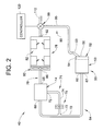
FIG. 2 is a block diagram illustrating the thermal pneumatic deicing system ofFIG. 1 - A detailed description of one or more embodiments of the disclosed apparatus and method are presented herein by way of exemplification and not limitation with reference to the Figures.
- An aircraft, in accordance with an exemplary embodiment, is indicated generally at 2 in
FIG. 1 .Aircraft 2 includes a fuselage 4 extending from a nose portion 6 to atail portion 8 through abody portion 10.Body portion 10 houses anaircraft cabin 14 that includes acrew compartment 15 and apassenger compartment 16.Body portion 10 supports afirst wing 17 and asecond wing 18.First wing 17 extends from afirst root portion 20 to afirst tip portion 21 through afirst airfoil portion 23.First airfoil portion 23 includes a leadingedge 25 and atrailing edge 26.Second wing 18 extends from a second root portion (not shown) to asecond tip portion 31 through asecond airfoil portion 33.Second airfoil portion 33 includes a leadingedge 35 and atrailing edge 36.Tail portion 8 includes astabilizer 38. In the exemplary embodiment shown,aircraft 2 includes a thermalpneumatic deicing system 40. The term "deicing system" should be understood to describe a system that prevents ice build-up from surfaces and also may remove ice already built up on a surface. The term "thermal pneumatic deicing system" should be understood to describe a system that prevents and/or removes ice using conditioned air. - As shown in
FIG. 2 , thermalpneumatic deicing system 40 includes an environmental control system (ECS) 50 mounted inbody portion 10 ofaircraft 2. ECS 50 includes aninlet 52 which, in the exemplary embodiment shown, is positioned near leadingedge 25 of first wing 17 (FIG. 1 ). It should however be understood thatinlet 52 may be arranged in other locations.Inlet 52 is fluidically connected with aRAM air system 53 having a RAMair heat exchanger 54. RAMair heat exchanger 54 includes a RAM airheat exchanger face 56 that receives an airflow frominlet 52.RAM air system 53 also includes anoutlet 60 that delivers conditioned air toaircraft cabin 14 through acabin air duct 64. More specifically,cabin air duct 64 extends from afirst end 67, fluidically connected tooutlet 60, to asecond end 68 through anintermediate portion 70.Second end 68 is fluidically connected with, and delivers conditioned air to, aircraft cabin 14 (represented schematically as a box inFIG. 2 ). Arecirculation duct 71 extends from afirst end 72 to asecond end 73 through anintermediate portion 74 having afan 75.Fan 75 draws a portion of the conditioned air fromaircraft cabin 14 back tointermediate portion 70 ofcabin air duct 64. - An electronics
housing cooling duct 76 extends betweenaircraft cabin 14 and anelectronics housing 78.Electronics housing 78 includes afan 80 that draws cooling air fromaircraft cabin 14 to provide convection cooling for electronic components, indicated generally at 82. More specifically, electronicshousing cooling duct 76 extends from afirst end 85, fluidically connected toaircraft cabin 14, to asecond end 86 fluidically connected withelectronics housing 78. Cooling air fromaircraft cabin 14 is passed in a heat exchange relationship withelectronic components 82 forming a heated airflow.RAM air system 53 delivers ambient air toaircraft cabin 14. The ambient air is conditioned, or heated, prior to enteringaircraft cabin 14. During flight, RAMair heat exchanger 54 may experience an icing condition that reduces airflow efficiency. In particular, ice may form at RAM airheat exchanger face 56 reducing airflow intoRAM air system 53. - In accordance with the exemplary embodiment, thermal
pneumatic deicing system 40 includes adeicing duct 90 that selectively delivers the heated airflow fromelectronics housing 78 to RAMair heat exchanger 54. More specifically,deicing duct 90 extends from afirst end section 92, fluidically connected withelectronics housing 78, to asecond end section 93 through anintermediate section 95.Second end section 93 is positioned to deliver the heated airflow onto RAM airheat exchanger face 56 and into RAMair heat exchanger 54. The heated airflow thaws any ice than may have formed on RAMair heat exchanger 54. Avalve 99 is arranged alongintermediate section 95. Valve 99 selectively delivers the heated airflow to RAMair heat exchanger 54 and anoutlet duct 110 that leads to ambient.Outlet duct 110 is provided inbody portion 10 of fuselage 4 (as shown inFIG. 1 ). Acontroller 120 is operatively connected tovalve 99.Controller 120 may include sensors (not shown) that indicate an ice build up on RAM airheat exchanger face 56 or may selectively commandvalve 99 to open and divert the heated airflow from passing to ambient and, instead, flow to RAMair heat exchanger 54 during flight conditions known to produce ice. - At this point it should be understood that the exemplary embodiment describes a system that selectively delivers heated airflow from an electronics housing to a RAM air heat exchanger for deicing. The thermal pneumatic deicing system includes a controller that operates a valve to deliver a deicing airflow to the RAM air heat exchanger or releases the heated airflow to ambient. The controller may use sensors to detect an icing condition or may deliver the deicing airflow under flight conditions known to produce icing. Further, it should be understood that the type, number, and location of the electronic components may vary. It should also be understood that additional components, accessories, ducts and the like may be fluidically connected to the deicing system.
- While the invention has been described with reference to an exemplary embodiment or embodiments, it will be understood by those skilled in the art that various changes may be made and equivalents may be substituted for elements thereof without departing from the scope of the invention. In addition, many modifications may be made to adapt a particular situation or material to the teachings of the invention without departing from the essential scope thereof. Therefore, it is intended that the invention not be limited to the particular embodiment disclosed as the best mode contemplated for carrying out this invention, but that the invention will include all embodiments falling within the scope of the claims.
Claims (8)
- A thermal pneumatic deicing system (40) for deicing a RAM air heat exchanger (54) comprising:an environmental control system (ECS) (50) including a RAM air heat exchanger (54) and an outlet (60);an electronics housing (78) including a plurality of electronic components (82);a deicing duct (90) fluidically connecting the RAM air heat exchanger (54) and the electronics housing (78), the deicing duct (90) including a valve (99); anda controller (120) operatively connected to the valve (99), the controller (120) being configured and disposed to selectively fluidically connect the RAM air heat exchanger (54) and the electronics housing (78) to facilitate deicing of the heat exchanger (54).
- The thermal pneumatic deicing system according to claim 1, wherein the ECS (50) includes an inlet (52) configured and disposed to direct an airflow through the RAM air heat exchanger (54) toward the outlet (60).
- The thermal pneumatic deicing system according to claim 1 or 2, further comprising: an aircraft cabin (14) and a cabin air duct (64) extending from a first end (67) fluidically connected to the outlet (60) to a second end (68) fluidically connected to the aircraft cabin (14) through an intermediate portion (70).
- The thermal pneumatic deicing system according to claim 3, further comprising: a recirculation duct (71) fluidically connected between the aircraft cabin (14) and the intermediate portion (70) of the cabin air duct (64).
- The thermal pneumatic deicing system according to claim 3 or 4, further comprising: an electronics housing cooling duct (76) extending from a first end (85) fluidically connected to the aircraft cabin (14) to a second end (86) fluidically connected to the electronics housing (78).
- The thermal pneumatic deicing system according to any preceding claim, further comprising: an outlet duct (110) fluidically connected between the valve (99) and ambient.
- An aircraft (2) comprising:a fuselage (4) extending from a nose portion (6) to a tail portion (8) through a body portion (10), the fuselage (4) including an aircraft cabin (14);first and second wings (17, 18) projecting from the body portion (10); anda thermal pneumatic deicing system (40) according to any preceding claim.
- A method of demising a RAM air heat exchanger (54) in an aircraft (2) comprising:directing a cooling air flow into an electronics housing (78);exchanging heat between electronics in the electronics housings and the cooling airflow, forming a heated airflow; andselectively guiding the heated airflow to the RAM air heat exchanger (54).
Applications Claiming Priority (1)
| Application Number | Priority Date | Filing Date | Title |
|---|---|---|---|
| US13/901,714 US9187180B2 (en) | 2013-05-24 | 2013-05-24 | Thermal pneumatic deicing system for an aircraft RAM air heat exchanger |
Publications (2)
| Publication Number | Publication Date |
|---|---|
| EP2805882A1 true EP2805882A1 (en) | 2014-11-26 |
| EP2805882B1 EP2805882B1 (en) | 2016-04-27 |
Family
ID=50842057
Family Applications (1)
| Application Number | Title | Priority Date | Filing Date |
|---|---|---|---|
| EP14169521.3A Active EP2805882B1 (en) | 2013-05-24 | 2014-05-22 | Thermal pneumatic deicing system for an aircraft ram air heat exchanger |
Country Status (2)
| Country | Link |
|---|---|
| US (1) | US9187180B2 (en) |
| EP (1) | EP2805882B1 (en) |
Families Citing this family (2)
| Publication number | Priority date | Publication date | Assignee | Title |
|---|---|---|---|---|
| US10995997B2 (en) | 2018-06-26 | 2021-05-04 | Hamilton Sunstrand Corporation | Heat exchanger with integral features |
| US11333438B2 (en) | 2018-06-26 | 2022-05-17 | Hamilton Sundstrand Corporation | Heat exchanger with water extraction |
Citations (3)
| Publication number | Priority date | Publication date | Assignee | Title |
|---|---|---|---|---|
| US5553461A (en) * | 1995-01-11 | 1996-09-10 | Grumman Aerospace Corporation | Anti-icing heat exchanger for aircraft air cycle performance enhancement |
| US6408641B1 (en) * | 2001-03-27 | 2002-06-25 | Lockheed Martin Corporation | Hybrid turbine coolant system |
| US6663044B1 (en) * | 2001-09-20 | 2003-12-16 | Hamilton Sundstrand Corporation | Vapor compression cycle environmental control system |
Family Cites Families (30)
| Publication number | Priority date | Publication date | Assignee | Title |
|---|---|---|---|---|
| US2465728A (en) * | 1944-08-16 | 1949-03-29 | Cons Vultee Aircraft Corp | Air scoop |
| US3981466A (en) * | 1974-12-23 | 1976-09-21 | The Boeing Company | Integrated thermal anti-icing and environmental control system |
| US4406431A (en) * | 1981-11-23 | 1983-09-27 | Omac, Inc. | Air scoop lip warmer de-icing system |
| US4504030A (en) | 1982-12-06 | 1985-03-12 | United Technologies Corporation | Cooling means |
| US5043558A (en) * | 1990-09-26 | 1991-08-27 | Weed Instrument Company, Inc. | Deicing apparatus and method utilizing heat distributing means contained within surface channels |
| US5253484A (en) * | 1991-08-22 | 1993-10-19 | The Boeing Company | High reliability avionic cooling system |
| US5327744A (en) | 1992-12-18 | 1994-07-12 | United Technologies Corporation | Integrated environmental control system for a helicopter |
| GB9508043D0 (en) * | 1995-04-20 | 1995-06-07 | British Aerospace | Environmental control system |
| US6205803B1 (en) * | 1996-04-26 | 2001-03-27 | Mainstream Engineering Corporation | Compact avionics-pod-cooling unit thermal control method and apparatus |
| US5701755A (en) * | 1997-01-15 | 1997-12-30 | Sundstrand Corporation | Cooling of aircraft electronic heat loads |
| DE10119433C1 (en) * | 2001-04-20 | 2002-08-22 | Liebherr Aerospace Gmbh | Ram air duct for an aircraft air conditioning system |
| DE10361658B4 (en) * | 2003-12-30 | 2008-05-08 | Airbus Deutschland Gmbh | Apparatus and method for heating an aircraft cabin |
| DE102005003645B4 (en) * | 2005-01-26 | 2010-04-08 | Airbus Deutschland Gmbh | air system |
| DE102006001685B4 (en) | 2006-01-12 | 2009-11-12 | Airbus Deutschland Gmbh | Method and system for controlling the pressure in an aircraft cabin |
| DE102006037539B4 (en) * | 2006-08-10 | 2012-04-26 | Airbus Operations Gmbh | Air conditioning system with anti-icing for an aircraft |
| ATE432873T1 (en) | 2006-09-25 | 2009-06-15 | Saab Ab | AVIONICS COOLING |
| US20090084896A1 (en) | 2007-09-27 | 2009-04-02 | Hamilton Sundstrand Corporation | Cabin air system for aviation electronics |
| ATE525283T1 (en) | 2007-11-13 | 2011-10-15 | Boeing Co | CABIN AIR AND HEAT EXCHANGER AIR INLETS FOR AIRCRAFT CLIMATE CONTROL SYSTEMS AND ASSOCIATED METHOD OF USE |
| US8351200B2 (en) | 2007-11-19 | 2013-01-08 | International Business Machines Corporation | Convergence of air water cooling of an electronics rack and a computer room in a single unit |
| US7975966B2 (en) * | 2008-02-04 | 2011-07-12 | Embraer - Empresa Brasileira De Aeronautica S.A. | Icing protection for aircraft air inlet scoops |
| DE102008019146A1 (en) * | 2008-04-16 | 2009-11-05 | Airbus Deutschland Gmbh | Deicing system for an aircraft |
| DE102008025951B4 (en) * | 2008-05-30 | 2010-10-28 | Airbus Deutschland Gmbh | Cooling an electronic device in an aircraft by a case-wise single-phase or two-phase cooling |
| US8061657B2 (en) * | 2008-12-31 | 2011-11-22 | General Electric Company | Method and apparatus for aircraft anti-icing |
| CN102893454B (en) * | 2010-02-05 | 2014-12-10 | 萨博公司 | Air heaters for air inlets of electronic systems |
| US20110259546A1 (en) | 2010-04-27 | 2011-10-27 | Hamilton Sundstrand Corporation | Ram flow modulation valve |
| FR2975254B1 (en) | 2011-05-13 | 2013-06-28 | Airbus Operations Sas | METHOD FOR COOLING AIR DISTRIBUTION FOR ELECTRICAL EQUIPMENT MOUNTED IN AN AIRCRAFT AND AIRCRAFT BAY EQUIPPED WITH SUCH A BAY |
| US20120312037A1 (en) | 2011-06-08 | 2012-12-13 | Hamilton Sundstrand Corporation | Vapor cycle system with de-superheater |
| US9114881B2 (en) * | 2011-11-16 | 2015-08-25 | The Boeing Company | Aircraft modular cooling system |
| US20140109603A1 (en) * | 2011-12-29 | 2014-04-24 | Embraer S.A. | Integrated environmental control systems and methods for controlling environmental temperature of an enclosed space |
| DE102012006628B4 (en) * | 2012-03-30 | 2019-05-23 | Airbus Operations Gmbh | Redundant integrated liquid cooling system for avionics |
-
2013
- 2013-05-24 US US13/901,714 patent/US9187180B2/en active Active
-
2014
- 2014-05-22 EP EP14169521.3A patent/EP2805882B1/en active Active
Patent Citations (3)
| Publication number | Priority date | Publication date | Assignee | Title |
|---|---|---|---|---|
| US5553461A (en) * | 1995-01-11 | 1996-09-10 | Grumman Aerospace Corporation | Anti-icing heat exchanger for aircraft air cycle performance enhancement |
| US6408641B1 (en) * | 2001-03-27 | 2002-06-25 | Lockheed Martin Corporation | Hybrid turbine coolant system |
| US6663044B1 (en) * | 2001-09-20 | 2003-12-16 | Hamilton Sundstrand Corporation | Vapor compression cycle environmental control system |
Also Published As
| Publication number | Publication date |
|---|---|
| EP2805882B1 (en) | 2016-04-27 |
| US9187180B2 (en) | 2015-11-17 |
| US20140346278A1 (en) | 2014-11-27 |
Similar Documents
| Publication | Publication Date | Title |
|---|---|---|
| EP2815964A1 (en) | Active aircraft brake cooling system | |
| EP2785590B1 (en) | System and method for cooling an aircraft wing | |
| CN102007037B (en) | De-icing system for an airplane | |
| CN103359281B (en) | For the surface element of aircraft and relevant aircraft and method | |
| EP3031713B1 (en) | Aircraft wing rib | |
| US20160137305A1 (en) | Electric propulsion assembly for an aircraft | |
| US20180170557A1 (en) | Leading edge ice-protection system | |
| CN103419929A (en) | Wing for an aircraft, aircraft and method for reducing aerodynamic drag and improving maximum lift | |
| KR101710691B1 (en) | Air generator for an aircraft | |
| EP2230175A3 (en) | Microvanes for aircraft aft body drag reduction | |
| EP2703291A2 (en) | Inlet icing protection simulation system | |
| EP3315401A1 (en) | Air distribution system with drag reducing inlet | |
| CN111032511A (en) | Device and method for supplying air to a pneumatic load on an aircraft | |
| EP3594124A1 (en) | Ice protection system for a component of an aerodynamic system | |
| EP2805882B1 (en) | Thermal pneumatic deicing system for an aircraft ram air heat exchanger | |
| EP1699686B1 (en) | Method and device for suctioning the boundary layer | |
| EP3118459B1 (en) | Ram air fan assembly with surge detection | |
| CN109383813A (en) | Aircraft comprising being located at the air-conditioning device of aircraft tip | |
| US20100258655A1 (en) | Ram air outlet duct | |
| US9366367B2 (en) | Cooling tube for a ram air fan (RAF) assembly | |
| EP2899126B1 (en) | Pressure equalization vent for use in an aircraft assembly | |
| JP2003205899A (en) | Arrangement structure of air conditioner in airplane | |
| US9365296B2 (en) | Transfer tube for a ram air fan (RAF) assembly | |
| CA3027484C (en) | Duct and method for directing a flow of air from an air-cooled device onboard an aircraft | |
| US20190256213A1 (en) | Duct and method for directing a flow of air from an air-cooled device onboard an aircraft |
Legal Events
| Date | Code | Title | Description |
|---|---|---|---|
| PUAI | Public reference made under article 153(3) epc to a published international application that has entered the european phase |
Free format text: ORIGINAL CODE: 0009012 |
|
| 17P | Request for examination filed |
Effective date: 20140522 |
|
| AK | Designated contracting states |
Kind code of ref document: A1 Designated state(s): AL AT BE BG CH CY CZ DE DK EE ES FI FR GB GR HR HU IE IS IT LI LT LU LV MC MK MT NL NO PL PT RO RS SE SI SK SM TR |
|
| AX | Request for extension of the european patent |
Extension state: BA ME |
|
| R17P | Request for examination filed (corrected) |
Effective date: 20150522 |
|
| RBV | Designated contracting states (corrected) |
Designated state(s): AL AT BE BG CH CY CZ DE DK EE ES FI FR GB GR HR HU IE IS IT LI LT LU LV MC MK MT NL NO PL PT RO RS SE SI SK SM TR |
|
| GRAP | Despatch of communication of intention to grant a patent |
Free format text: ORIGINAL CODE: EPIDOSNIGR1 |
|
| INTG | Intention to grant announced |
Effective date: 20151103 |
|
| GRAS | Grant fee paid |
Free format text: ORIGINAL CODE: EPIDOSNIGR3 |
|
| GRAA | (expected) grant |
Free format text: ORIGINAL CODE: 0009210 |
|
| AK | Designated contracting states |
Kind code of ref document: B1 Designated state(s): AL AT BE BG CH CY CZ DE DK EE ES FI FR GB GR HR HU IE IS IT LI LT LU LV MC MK MT NL NO PL PT RO RS SE SI SK SM TR |
|
| REG | Reference to a national code |
Ref country code: GB Ref legal event code: FG4D |
|
| REG | Reference to a national code |
Ref country code: CH Ref legal event code: EP |
|
| REG | Reference to a national code |
Ref country code: AT Ref legal event code: REF Ref document number: 794478 Country of ref document: AT Kind code of ref document: T Effective date: 20160515 |
|
| REG | Reference to a national code |
Ref country code: IE Ref legal event code: FG4D |
|
| REG | Reference to a national code |
Ref country code: FR Ref legal event code: PLFP Year of fee payment: 3 |
|
| REG | Reference to a national code |
Ref country code: DE Ref legal event code: R096 Ref document number: 602014001655 Country of ref document: DE |
|
| REG | Reference to a national code |
Ref country code: LT Ref legal event code: MG4D |
|
| PG25 | Lapsed in a contracting state [announced via postgrant information from national office to epo] |
Ref country code: BE Free format text: LAPSE BECAUSE OF NON-PAYMENT OF DUE FEES Effective date: 20160531 |
|
| REG | Reference to a national code |
Ref country code: NL Ref legal event code: MP Effective date: 20160427 |
|
| REG | Reference to a national code |
Ref country code: AT Ref legal event code: MK05 Ref document number: 794478 Country of ref document: AT Kind code of ref document: T Effective date: 20160427 |
|
| PG25 | Lapsed in a contracting state [announced via postgrant information from national office to epo] |
Ref country code: NL Free format text: LAPSE BECAUSE OF FAILURE TO SUBMIT A TRANSLATION OF THE DESCRIPTION OR TO PAY THE FEE WITHIN THE PRESCRIBED TIME-LIMIT Effective date: 20160427 |
|
| PG25 | Lapsed in a contracting state [announced via postgrant information from national office to epo] |
Ref country code: LT Free format text: LAPSE BECAUSE OF FAILURE TO SUBMIT A TRANSLATION OF THE DESCRIPTION OR TO PAY THE FEE WITHIN THE PRESCRIBED TIME-LIMIT Effective date: 20160427 Ref country code: FI Free format text: LAPSE BECAUSE OF FAILURE TO SUBMIT A TRANSLATION OF THE DESCRIPTION OR TO PAY THE FEE WITHIN THE PRESCRIBED TIME-LIMIT Effective date: 20160427 Ref country code: NO Free format text: LAPSE BECAUSE OF FAILURE TO SUBMIT A TRANSLATION OF THE DESCRIPTION OR TO PAY THE FEE WITHIN THE PRESCRIBED TIME-LIMIT Effective date: 20160727 Ref country code: PL Free format text: LAPSE BECAUSE OF FAILURE TO SUBMIT A TRANSLATION OF THE DESCRIPTION OR TO PAY THE FEE WITHIN THE PRESCRIBED TIME-LIMIT Effective date: 20160427 |
|
| PG25 | Lapsed in a contracting state [announced via postgrant information from national office to epo] |
Ref country code: HR Free format text: LAPSE BECAUSE OF FAILURE TO SUBMIT A TRANSLATION OF THE DESCRIPTION OR TO PAY THE FEE WITHIN THE PRESCRIBED TIME-LIMIT Effective date: 20160427 Ref country code: RS Free format text: LAPSE BECAUSE OF FAILURE TO SUBMIT A TRANSLATION OF THE DESCRIPTION OR TO PAY THE FEE WITHIN THE PRESCRIBED TIME-LIMIT Effective date: 20160427 Ref country code: PT Free format text: LAPSE BECAUSE OF FAILURE TO SUBMIT A TRANSLATION OF THE DESCRIPTION OR TO PAY THE FEE WITHIN THE PRESCRIBED TIME-LIMIT Effective date: 20160829 Ref country code: SE Free format text: LAPSE BECAUSE OF FAILURE TO SUBMIT A TRANSLATION OF THE DESCRIPTION OR TO PAY THE FEE WITHIN THE PRESCRIBED TIME-LIMIT Effective date: 20160427 Ref country code: ES Free format text: LAPSE BECAUSE OF FAILURE TO SUBMIT A TRANSLATION OF THE DESCRIPTION OR TO PAY THE FEE WITHIN THE PRESCRIBED TIME-LIMIT Effective date: 20160427 Ref country code: AT Free format text: LAPSE BECAUSE OF FAILURE TO SUBMIT A TRANSLATION OF THE DESCRIPTION OR TO PAY THE FEE WITHIN THE PRESCRIBED TIME-LIMIT Effective date: 20160427 Ref country code: LV Free format text: LAPSE BECAUSE OF FAILURE TO SUBMIT A TRANSLATION OF THE DESCRIPTION OR TO PAY THE FEE WITHIN THE PRESCRIBED TIME-LIMIT Effective date: 20160427 Ref country code: GR Free format text: LAPSE BECAUSE OF FAILURE TO SUBMIT A TRANSLATION OF THE DESCRIPTION OR TO PAY THE FEE WITHIN THE PRESCRIBED TIME-LIMIT Effective date: 20160728 |
|
| REG | Reference to a national code |
Ref country code: DE Ref legal event code: R119 Ref document number: 602014001655 Country of ref document: DE |
|
| PG25 | Lapsed in a contracting state [announced via postgrant information from national office to epo] |
Ref country code: IT Free format text: LAPSE BECAUSE OF FAILURE TO SUBMIT A TRANSLATION OF THE DESCRIPTION OR TO PAY THE FEE WITHIN THE PRESCRIBED TIME-LIMIT Effective date: 20160427 Ref country code: BE Free format text: LAPSE BECAUSE OF FAILURE TO SUBMIT A TRANSLATION OF THE DESCRIPTION OR TO PAY THE FEE WITHIN THE PRESCRIBED TIME-LIMIT Effective date: 20160427 |
|
| PG25 | Lapsed in a contracting state [announced via postgrant information from national office to epo] |
Ref country code: EE Free format text: LAPSE BECAUSE OF FAILURE TO SUBMIT A TRANSLATION OF THE DESCRIPTION OR TO PAY THE FEE WITHIN THE PRESCRIBED TIME-LIMIT Effective date: 20160427 Ref country code: MC Free format text: LAPSE BECAUSE OF FAILURE TO SUBMIT A TRANSLATION OF THE DESCRIPTION OR TO PAY THE FEE WITHIN THE PRESCRIBED TIME-LIMIT Effective date: 20160427 Ref country code: RO Free format text: LAPSE BECAUSE OF FAILURE TO SUBMIT A TRANSLATION OF THE DESCRIPTION OR TO PAY THE FEE WITHIN THE PRESCRIBED TIME-LIMIT Effective date: 20160427 Ref country code: DK Free format text: LAPSE BECAUSE OF FAILURE TO SUBMIT A TRANSLATION OF THE DESCRIPTION OR TO PAY THE FEE WITHIN THE PRESCRIBED TIME-LIMIT Effective date: 20160427 Ref country code: SK Free format text: LAPSE BECAUSE OF FAILURE TO SUBMIT A TRANSLATION OF THE DESCRIPTION OR TO PAY THE FEE WITHIN THE PRESCRIBED TIME-LIMIT Effective date: 20160427 Ref country code: CZ Free format text: LAPSE BECAUSE OF FAILURE TO SUBMIT A TRANSLATION OF THE DESCRIPTION OR TO PAY THE FEE WITHIN THE PRESCRIBED TIME-LIMIT Effective date: 20160427 |
|
| REG | Reference to a national code |
Ref country code: IE Ref legal event code: MM4A |
|
| PG25 | Lapsed in a contracting state [announced via postgrant information from national office to epo] |
Ref country code: SM Free format text: LAPSE BECAUSE OF FAILURE TO SUBMIT A TRANSLATION OF THE DESCRIPTION OR TO PAY THE FEE WITHIN THE PRESCRIBED TIME-LIMIT Effective date: 20160427 |
|
| PLBE | No opposition filed within time limit |
Free format text: ORIGINAL CODE: 0009261 |
|
| STAA | Information on the status of an ep patent application or granted ep patent |
Free format text: STATUS: NO OPPOSITION FILED WITHIN TIME LIMIT |
|
| 26N | No opposition filed |
Effective date: 20170130 |
|
| REG | Reference to a national code |
Ref country code: FR Ref legal event code: PLFP Year of fee payment: 4 |
|
| PG25 | Lapsed in a contracting state [announced via postgrant information from national office to epo] |
Ref country code: DE Free format text: LAPSE BECAUSE OF NON-PAYMENT OF DUE FEES Effective date: 20161201 |
|
| PG25 | Lapsed in a contracting state [announced via postgrant information from national office to epo] |
Ref country code: IE Free format text: LAPSE BECAUSE OF NON-PAYMENT OF DUE FEES Effective date: 20160522 Ref country code: SI Free format text: LAPSE BECAUSE OF FAILURE TO SUBMIT A TRANSLATION OF THE DESCRIPTION OR TO PAY THE FEE WITHIN THE PRESCRIBED TIME-LIMIT Effective date: 20160427 |
|
| REG | Reference to a national code |
Ref country code: CH Ref legal event code: PL |
|
| PG25 | Lapsed in a contracting state [announced via postgrant information from national office to epo] |
Ref country code: CH Free format text: LAPSE BECAUSE OF NON-PAYMENT OF DUE FEES Effective date: 20170531 Ref country code: LI Free format text: LAPSE BECAUSE OF NON-PAYMENT OF DUE FEES Effective date: 20170531 |
|
| REG | Reference to a national code |
Ref country code: FR Ref legal event code: PLFP Year of fee payment: 5 |
|
| PG25 | Lapsed in a contracting state [announced via postgrant information from national office to epo] |
Ref country code: HU Free format text: LAPSE BECAUSE OF FAILURE TO SUBMIT A TRANSLATION OF THE DESCRIPTION OR TO PAY THE FEE WITHIN THE PRESCRIBED TIME-LIMIT; INVALID AB INITIO Effective date: 20140522 |
|
| PG25 | Lapsed in a contracting state [announced via postgrant information from national office to epo] |
Ref country code: MK Free format text: LAPSE BECAUSE OF FAILURE TO SUBMIT A TRANSLATION OF THE DESCRIPTION OR TO PAY THE FEE WITHIN THE PRESCRIBED TIME-LIMIT Effective date: 20160427 Ref country code: CY Free format text: LAPSE BECAUSE OF FAILURE TO SUBMIT A TRANSLATION OF THE DESCRIPTION OR TO PAY THE FEE WITHIN THE PRESCRIBED TIME-LIMIT Effective date: 20160427 Ref country code: IS Free format text: LAPSE BECAUSE OF FAILURE TO SUBMIT A TRANSLATION OF THE DESCRIPTION OR TO PAY THE FEE WITHIN THE PRESCRIBED TIME-LIMIT Effective date: 20160427 Ref country code: LU Free format text: LAPSE BECAUSE OF NON-PAYMENT OF DUE FEES Effective date: 20160522 Ref country code: MT Free format text: LAPSE BECAUSE OF NON-PAYMENT OF DUE FEES Effective date: 20160531 |
|
| PG25 | Lapsed in a contracting state [announced via postgrant information from national office to epo] |
Ref country code: BG Free format text: LAPSE BECAUSE OF FAILURE TO SUBMIT A TRANSLATION OF THE DESCRIPTION OR TO PAY THE FEE WITHIN THE PRESCRIBED TIME-LIMIT Effective date: 20160427 |
|
| PG25 | Lapsed in a contracting state [announced via postgrant information from national office to epo] |
Ref country code: TR Free format text: LAPSE BECAUSE OF FAILURE TO SUBMIT A TRANSLATION OF THE DESCRIPTION OR TO PAY THE FEE WITHIN THE PRESCRIBED TIME-LIMIT Effective date: 20160427 Ref country code: AL Free format text: LAPSE BECAUSE OF FAILURE TO SUBMIT A TRANSLATION OF THE DESCRIPTION OR TO PAY THE FEE WITHIN THE PRESCRIBED TIME-LIMIT Effective date: 20160427 |
|
| P01 | Opt-out of the competence of the unified patent court (upc) registered |
Effective date: 20230522 |
|
| PGFP | Annual fee paid to national office [announced via postgrant information from national office to epo] |
Ref country code: GB Payment date: 20250423 Year of fee payment: 12 |
|
| PGFP | Annual fee paid to national office [announced via postgrant information from national office to epo] |
Ref country code: FR Payment date: 20250423 Year of fee payment: 12 |