EP2805768A1 - Method of producing fiber catalyst and a fiber catalyst - Google Patents
Method of producing fiber catalyst and a fiber catalyst Download PDFInfo
- Publication number
- EP2805768A1 EP2805768A1 EP20140151608 EP14151608A EP2805768A1 EP 2805768 A1 EP2805768 A1 EP 2805768A1 EP 20140151608 EP20140151608 EP 20140151608 EP 14151608 A EP14151608 A EP 14151608A EP 2805768 A1 EP2805768 A1 EP 2805768A1
- Authority
- EP
- European Patent Office
- Prior art keywords
- fiber
- catalysts
- specific shape
- producing
- melting point
- Prior art date
- Legal status (The legal status is an assumption and is not a legal conclusion. Google has not performed a legal analysis and makes no representation as to the accuracy of the status listed.)
- Granted
Links
Images

Classifications
-
- B—PERFORMING OPERATIONS; TRANSPORTING
- B01—PHYSICAL OR CHEMICAL PROCESSES OR APPARATUS IN GENERAL
- B01J—CHEMICAL OR PHYSICAL PROCESSES, e.g. CATALYSIS OR COLLOID CHEMISTRY; THEIR RELEVANT APPARATUS
- B01J23/00—Catalysts comprising metals or metal oxides or hydroxides, not provided for in group B01J21/00
- B01J23/38—Catalysts comprising metals or metal oxides or hydroxides, not provided for in group B01J21/00 of noble metals
- B01J23/40—Catalysts comprising metals or metal oxides or hydroxides, not provided for in group B01J21/00 of noble metals of the platinum group metals
-
- B—PERFORMING OPERATIONS; TRANSPORTING
- B01—PHYSICAL OR CHEMICAL PROCESSES OR APPARATUS IN GENERAL
- B01J—CHEMICAL OR PHYSICAL PROCESSES, e.g. CATALYSIS OR COLLOID CHEMISTRY; THEIR RELEVANT APPARATUS
- B01J31/00—Catalysts comprising hydrides, coordination complexes or organic compounds
- B01J31/02—Catalysts comprising hydrides, coordination complexes or organic compounds containing organic compounds or metal hydrides
- B01J31/06—Catalysts comprising hydrides, coordination complexes or organic compounds containing organic compounds or metal hydrides containing polymers
- B01J31/08—Ion-exchange resins
-
- B—PERFORMING OPERATIONS; TRANSPORTING
- B01—PHYSICAL OR CHEMICAL PROCESSES OR APPARATUS IN GENERAL
- B01J—CHEMICAL OR PHYSICAL PROCESSES, e.g. CATALYSIS OR COLLOID CHEMISTRY; THEIR RELEVANT APPARATUS
- B01J23/00—Catalysts comprising metals or metal oxides or hydroxides, not provided for in group B01J21/00
- B01J23/38—Catalysts comprising metals or metal oxides or hydroxides, not provided for in group B01J21/00 of noble metals
- B01J23/48—Silver or gold
-
- B—PERFORMING OPERATIONS; TRANSPORTING
- B01—PHYSICAL OR CHEMICAL PROCESSES OR APPARATUS IN GENERAL
- B01J—CHEMICAL OR PHYSICAL PROCESSES, e.g. CATALYSIS OR COLLOID CHEMISTRY; THEIR RELEVANT APPARATUS
- B01J23/00—Catalysts comprising metals or metal oxides or hydroxides, not provided for in group B01J21/00
- B01J23/38—Catalysts comprising metals or metal oxides or hydroxides, not provided for in group B01J21/00 of noble metals
- B01J23/54—Catalysts comprising metals or metal oxides or hydroxides, not provided for in group B01J21/00 of noble metals combined with metals, oxides or hydroxides provided for in groups B01J23/02 - B01J23/36
- B01J23/56—Platinum group metals
-
- B—PERFORMING OPERATIONS; TRANSPORTING
- B01—PHYSICAL OR CHEMICAL PROCESSES OR APPARATUS IN GENERAL
- B01J—CHEMICAL OR PHYSICAL PROCESSES, e.g. CATALYSIS OR COLLOID CHEMISTRY; THEIR RELEVANT APPARATUS
- B01J35/00—Catalysts, in general, characterised by their form or physical properties
- B01J35/50—Catalysts, in general, characterised by their form or physical properties characterised by their shape or configuration
- B01J35/58—Fabrics or filaments
-
- B—PERFORMING OPERATIONS; TRANSPORTING
- B01—PHYSICAL OR CHEMICAL PROCESSES OR APPARATUS IN GENERAL
- B01J—CHEMICAL OR PHYSICAL PROCESSES, e.g. CATALYSIS OR COLLOID CHEMISTRY; THEIR RELEVANT APPARATUS
- B01J37/00—Processes, in general, for preparing catalysts; Processes, in general, for activation of catalysts
- B01J37/02—Impregnation, coating or precipitation
- B01J37/03—Precipitation; Co-precipitation
- B01J37/036—Precipitation; Co-precipitation to form a gel or a cogel
-
- B—PERFORMING OPERATIONS; TRANSPORTING
- B01—PHYSICAL OR CHEMICAL PROCESSES OR APPARATUS IN GENERAL
- B01J—CHEMICAL OR PHYSICAL PROCESSES, e.g. CATALYSIS OR COLLOID CHEMISTRY; THEIR RELEVANT APPARATUS
- B01J37/00—Processes, in general, for preparing catalysts; Processes, in general, for activation of catalysts
- B01J37/32—Freeze drying, i.e. lyophilisation
-
- D—TEXTILES; PAPER
- D01—NATURAL OR MAN-MADE THREADS OR FIBRES; SPINNING
- D01D—MECHANICAL METHODS OR APPARATUS IN THE MANUFACTURE OF ARTIFICIAL FILAMENTS, THREADS, FIBRES, BRISTLES OR RIBBONS
- D01D5/00—Formation of filaments, threads, or the like
- D01D5/06—Wet spinning methods
-
- D—TEXTILES; PAPER
- D01—NATURAL OR MAN-MADE THREADS OR FIBRES; SPINNING
- D01F—CHEMICAL FEATURES IN THE MANUFACTURE OF ARTIFICIAL FILAMENTS, THREADS, FIBRES, BRISTLES OR RIBBONS; APPARATUS SPECIALLY ADAPTED FOR THE MANUFACTURE OF CARBON FILAMENTS
- D01F1/00—General methods for the manufacture of artificial filaments or the like
- D01F1/02—Addition of substances to the spinning solution or to the melt
- D01F1/10—Other agents for modifying properties
-
- D—TEXTILES; PAPER
- D01—NATURAL OR MAN-MADE THREADS OR FIBRES; SPINNING
- D01F—CHEMICAL FEATURES IN THE MANUFACTURE OF ARTIFICIAL FILAMENTS, THREADS, FIBRES, BRISTLES OR RIBBONS; APPARATUS SPECIALLY ADAPTED FOR THE MANUFACTURE OF CARBON FILAMENTS
- D01F11/00—Chemical after-treatment of artificial filaments or the like during manufacture
-
- H—ELECTRICITY
- H01—ELECTRIC ELEMENTS
- H01M—PROCESSES OR MEANS, e.g. BATTERIES, FOR THE DIRECT CONVERSION OF CHEMICAL ENERGY INTO ELECTRICAL ENERGY
- H01M4/00—Electrodes
- H01M4/86—Inert electrodes with catalytic activity, e.g. for fuel cells
- H01M4/8605—Porous electrodes
-
- H—ELECTRICITY
- H01—ELECTRIC ELEMENTS
- H01M—PROCESSES OR MEANS, e.g. BATTERIES, FOR THE DIRECT CONVERSION OF CHEMICAL ENERGY INTO ELECTRICAL ENERGY
- H01M4/00—Electrodes
- H01M4/86—Inert electrodes with catalytic activity, e.g. for fuel cells
- H01M4/8663—Selection of inactive substances as ingredients for catalytic active masses, e.g. binders, fillers
-
- H—ELECTRICITY
- H01—ELECTRIC ELEMENTS
- H01M—PROCESSES OR MEANS, e.g. BATTERIES, FOR THE DIRECT CONVERSION OF CHEMICAL ENERGY INTO ELECTRICAL ENERGY
- H01M4/00—Electrodes
- H01M4/86—Inert electrodes with catalytic activity, e.g. for fuel cells
- H01M4/88—Processes of manufacture
- H01M4/8803—Supports for the deposition of the catalytic active composition
- H01M4/8814—Temporary supports, e.g. decal
-
- H—ELECTRICITY
- H01—ELECTRIC ELEMENTS
- H01M—PROCESSES OR MEANS, e.g. BATTERIES, FOR THE DIRECT CONVERSION OF CHEMICAL ENERGY INTO ELECTRICAL ENERGY
- H01M4/00—Electrodes
- H01M4/86—Inert electrodes with catalytic activity, e.g. for fuel cells
- H01M4/88—Processes of manufacture
- H01M4/8825—Methods for deposition of the catalytic active composition
-
- H—ELECTRICITY
- H01—ELECTRIC ELEMENTS
- H01M—PROCESSES OR MEANS, e.g. BATTERIES, FOR THE DIRECT CONVERSION OF CHEMICAL ENERGY INTO ELECTRICAL ENERGY
- H01M4/00—Electrodes
- H01M4/86—Inert electrodes with catalytic activity, e.g. for fuel cells
- H01M4/88—Processes of manufacture
- H01M4/8875—Methods for shaping the electrode into free-standing bodies, like sheets, films or grids, e.g. moulding, hot-pressing, casting without support, extrusion without support
-
- H—ELECTRICITY
- H01—ELECTRIC ELEMENTS
- H01M—PROCESSES OR MEANS, e.g. BATTERIES, FOR THE DIRECT CONVERSION OF CHEMICAL ENERGY INTO ELECTRICAL ENERGY
- H01M4/00—Electrodes
- H01M4/86—Inert electrodes with catalytic activity, e.g. for fuel cells
- H01M4/90—Selection of catalytic material
- H01M4/9041—Metals or alloys
-
- H—ELECTRICITY
- H01—ELECTRIC ELEMENTS
- H01M—PROCESSES OR MEANS, e.g. BATTERIES, FOR THE DIRECT CONVERSION OF CHEMICAL ENERGY INTO ELECTRICAL ENERGY
- H01M4/00—Electrodes
- H01M4/86—Inert electrodes with catalytic activity, e.g. for fuel cells
- H01M4/90—Selection of catalytic material
- H01M4/92—Metals of platinum group
-
- D—TEXTILES; PAPER
- D01—NATURAL OR MAN-MADE THREADS OR FIBRES; SPINNING
- D01F—CHEMICAL FEATURES IN THE MANUFACTURE OF ARTIFICIAL FILAMENTS, THREADS, FIBRES, BRISTLES OR RIBBONS; APPARATUS SPECIALLY ADAPTED FOR THE MANUFACTURE OF CARBON FILAMENTS
- D01F9/00—Artificial filaments or the like of other substances; Manufacture thereof; Apparatus specially adapted for the manufacture of carbon filaments
- D01F9/04—Artificial filaments or the like of other substances; Manufacture thereof; Apparatus specially adapted for the manufacture of carbon filaments of alginates
-
- H—ELECTRICITY
- H01—ELECTRIC ELEMENTS
- H01M—PROCESSES OR MEANS, e.g. BATTERIES, FOR THE DIRECT CONVERSION OF CHEMICAL ENERGY INTO ELECTRICAL ENERGY
- H01M8/00—Fuel cells; Manufacture thereof
- H01M8/10—Fuel cells with solid electrolytes
- H01M2008/1095—Fuel cells with polymeric electrolytes
-
- Y—GENERAL TAGGING OF NEW TECHNOLOGICAL DEVELOPMENTS; GENERAL TAGGING OF CROSS-SECTIONAL TECHNOLOGIES SPANNING OVER SEVERAL SECTIONS OF THE IPC; TECHNICAL SUBJECTS COVERED BY FORMER USPC CROSS-REFERENCE ART COLLECTIONS [XRACs] AND DIGESTS
- Y02—TECHNOLOGIES OR APPLICATIONS FOR MITIGATION OR ADAPTATION AGAINST CLIMATE CHANGE
- Y02E—REDUCTION OF GREENHOUSE GAS [GHG] EMISSIONS, RELATED TO ENERGY GENERATION, TRANSMISSION OR DISTRIBUTION
- Y02E60/00—Enabling technologies; Technologies with a potential or indirect contribution to GHG emissions mitigation
- Y02E60/30—Hydrogen technology
- Y02E60/50—Fuel cells
Definitions
- the present invention relates to a method of producing a plurality of fiber catalysts; more particularly, the present invention relates to a method of producing hydrogen and a plurality of fiber catalysts having better reaction rates.
- Fuel cell uses the fuel as the anode which reacts with catalysts to generate hydrogen ions and electrons whereas said produced electrons travel through the electronic circuit toward the cathode and said hydrogen ions penetrate the proton exchange membrane inside the fuel cell while moving toward the cathode. The movement of electrons and hydrogen ions described above thus forms a current.
- the degree of catalyst activity can affect the time to produce hydrogen and the overall structure of a fuel cell design.
- the catalyst used in the conventional fuel cell to produce hydrogen is a metal active site supported on an organic carrier.
- the weight of the metal active site is only 10% of overall catalysts by weight whereas the organic carrier, which can not have the reaction of producing hydrogen, accounts for most of the catalysts. Therefore, it is difficult to improve the efficiency of hydrogen production.
- the hydrogen production process takes place in the triple phase points of the catalyst, fuel and liquid, and, in the later stage of hydrogen production process, byproducts of hydrogen production will hinder the flow of liquid resulting in a poor reaction rate of the fuel block in the later stage.
- a method of producing fiber catalysts of the present invention includes the following steps of: mixing a plurality of fiber material and a solvent to form a solution; putting the solution into a modeling container to form at least one specific shape fiber body; applying a shaping process to the specific shape fiber body; and cutting or milling the specific shape fiber body to form a plurality of fiber catalysts.
- the method of producing a plurality of fiber catalysts further includes the following steps of: washing the specific shape fiber body with water; and drying the specific shape fiber body after washing it with water.
- the method of producing a plurality of fiber catalysts further includes the following step of: applying a vacuum drying process to the specific shape fiber body.
- the method of producing a plurality of fiber catalysts further includes the following steps of: mixing the fiber catalyst, adhesive agent, and hydrogen fuel, wherein the fiber catalyst has a first melting point, and the adhesive agent has a second melting point; and filling the mixture of fiber catalyst, adhesive agent and hydrogen fuel into a mold to be heated to a temperature that is between the first melting point and the second melting point.
- the method of producing a plurality of fiber catalysts further includes the following step of: mixing the reinforcing fibers and fiber catalysts.
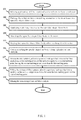
- FIG. 1 illustrates a flow chart of the method of producing a plurality of fiber catalysts of the first embodiment of the present invention
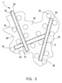
- FIG. 3 illustrates a schematic diagram of a plurality of fiber catalysts of the embodiment of the present invention.
- Step 101 Mix a plurality of fiber material and a solvent to form a solution.
- the fiber material 10 is sodium alginate, but the fiber material 10 is not limited to sodium alginate , it can be other fiber material 10 whose structure contains specific cation-exchange functional groups, such as cellulose, hemicellulose, ligin, polyvinyl alcohol, polyacrylonitrile, polypropylene, polyethylene, polystyrene, polytetrafluoroethene, polyacrylic acid, polyvinylchloride, viscose fiber or the material selected from the group consisting of cellulose, hemicellulose, ligin, sodium alginate, chitosan, polyvinyl alcohol, polyacrylonitrile, polypropylene, polyethylene, polystyrene, polytetrafluoroethene, polyacrylic acid, polyvinylchloride, viscose fiber and a combination thereof; whereas the source of the
- the specific cation-exchange functional groups of the fiber material 10 can be bonded to the metal ions to hold the metal ions fixedly on the fibers.
- the solvent of the first embodiment of the present invention is a combination of organic solvent of water, weak acid and ethanol, and however the materials of the solvent of the present invention are not limited to those described above.
- Step 102 Put the solution into a modeling container to form at least one specific shape fiber body.
- the modeling container is a spinning nozzle. After the solution is put in the spinning nozzle, the solution is injected through the spinneret of the spinning nozzle to form a specific shape fiber body.
- the specific shape fiber body is a plurality of fiber filaments.
- Step 103 Apply a shaping process to the specific shape fiber body.
- the shaping process is a coagulation bath of metal salts.
- the coagulation bath of metal salts of the first embodiment uses cobalt chloride solution.
- the component of the coagulation bath of metal salts of the present invention is not limited to the one described above.
- the metal ions used in the coagulation bath of metal salts can also be gold (Au), silver (Ag), palladium (Pd), platinum (Pt), rhodium (Rh), ruthenium (Ru), osmium (Os), iridium (Ir), Nickel (Ni), aluminum (Al), tungsten (W) or molybdenum (Mo), which can be combined with the polyvalent metal ions of the specific cation-exchange functional groups of the fiber material 10 to form a structure having special properties.
- the specific shape fiber body of fiber filaments is put through the coagulation bath of metal salts immediately.
- the metal ion of cobalt (Co 2+ ) of the coagulation bath of metal salts can undergo ion exchange with the sodium ion (Na + ) of the specific cation-exchange functional groups of the specific shape fiber body of the fiber material 10, and can become solidified on the surface of the specific shape fiber body of the fiber material 10, to form a water-insoluble cortex 20 of cobalt alginate (as shown in FIG.
- the interaction force which causes the metal ions and the specific cation-exchange functional groups to be bonded together, is Coulomb force, chelation, or covalent bonding force. With said interaction force, the metal ions and the specific cation-exchange functional groups are bonded together, to form a ring-like structure of chelate whereas said ring-like structure of chelate can provide a good stable efficacy.
- Step 104 Wash the specific shape fiber body with water.
- the specific shape fiber body After the specific shape fiber body has passed the coagulation bath of metal salts, the specific shape fiber body is placed and immersed in water so that the metal ions and other remaining ions of metal salts that are not bonded to the fiber material 10 in the solution are washed away.
- Step 105 Dry the specific shape fiber body after washing it with water.
- the specific shape fiber body is moved from water, and then is heated and dried to remove the moisture.
- the drying process of the present invention is not limited to heating and drying, and also can be freeze-dry or air-dry.
- Step 106 Cut or mill the specific shape fiber body to form a plurality of fiber catalysts.
- the specific shape fiber body is divided into a certain size to form a plurality of fiber catalysts 1, whereas the specific size of the present invention is 0.01 to 5mm in length and 10-100 ⁇ m in diameter. Nevertheless, the size of the specific shape fiber body of the present invention is not limited to said sizes described above, and the size of the specific shape fiber body can change according to the design requirement.
- Step 107 Mix the fiber catalyst, adhesive agent and hydrogen fuel, wherein the fiber catalyst has a first melting point and the adhesive agent has a second melting point, having the second melting point lower than the first melting point.
- the fiber catalyst 1, adhesive agent 30 and hydrogen fuel 40 are mixed together.
- the adhesive agent 30 of the present invention is hot melt powder and the hydrogen fuel 40 is sodium tetrahydridoborate.
- the fiber catalyst 1 has a first melting point; the adhesive agent 30 has a second melting point; and the second melting point of the adhesive agent 30 is lower than the first melting point of the fiber catalyst 1.
- the types of adhesive agent 30 and hydrogen fuel 40 of the present invention are not limited to those described above.
- Step 108 Fill the mixture of fiber catalyst, adhesive agent and hydrogen fuel into a mold to be heated to a temperature that is between the first melting point and the second melting point.
- the mixture of fiber catalyst 1, adhesive agent 30 and hydrogen fuel 40 are filled into a model to be heated to a temperature that is between the first melting point and the second melting point, to cause the adhesive agent 30 to melt. As shown in FIG. 3 , the fiber catalyst 1 and hydrogen fuel 40 can be bonded to each other through the melted adhesive agent 30.
- Step 109 Mix the reinforcing fibers and fiber catalysts.
- the reinforcing fibers and fiber catalysts are mixed to strengthen the structure of the fiber catalysts.
- the reinforcing fiber of the present invention is the rayon fiber.
- the present invention is not limited to said rayon fiber and can be other fibers with strengthening efficacy.
- FIG. 2 illustrates a flow chart of the method of producing a plurality of fiber catalysts of the second embodiment of the present invention.
- Step 201 Mix a plurality of fiber material and a solvent to form a solution.
- a plurality of fiber material 10 and a solvent are mixed and stirred to form a solution.
- the solvent is added in advance with metal salts wherein the type of metal ions of metal salts is, for example, cobalt, gold, silver, palladium, platinum, rhodium, ruthenium, osmium, iridium, nickel, aluminum, tungsten or molybdenum.
- the type of metal ions of metal salts of the present invention is not limited to those described above.
- Step 202 Put the solution into a modeling container to form at least one specific shape fiber body.
- the modeling container is a rectangular parallelepiped container. After the solution is put in the rectangular parallelepiped container, the solution forms a specific shape fiber body in the shape of rectangular parallelepiped.
- the modeling container is not limited to be a rectangular parallelepiped and can also be a container of other shapes, such that after the solution is placed in the modeling container, it then forms a specific shape fiber body corresponding to the shape of the modeling container.
- Step 203 Apply a shaping process to the specific shape fiber body.
- the shaping process is a freezing process, wherein the specific shape fiber body placed in the modeling container is frozen into a solid state in an environment below 0°C.
- the temperature of the freezing process of the present invention is not limited to temperatures below 0 °C.
- Step 204 Apply a vacuum drying process to the specific shape fiber body.
- the specific shape fiber body undergoes a vacuum drying process in an environment below 0°C to remove the excess moisture.
- Step 205 Cut or mill the specific shape fiber body to form a plurality of fiber catalysts.
- the size of the specific shape fiber body of the present invention is 0.01 to 5mm in length and 10-100 ⁇ m in diameter.
- the size of the specific shape fiber body of the present invention is not limited to said sizes described above, and the size of the specific shape fiber body can change according to the design requirement.
- Step 206 Mix the fiber catalyst, adhesive agent and hydrogen fuel, wherein the fiber catalyst has a first melting point and the adhesive agent has a second melting point, having the second melting point lower than the first melting point.
- the fiber catalyst 1, adhesive agent 30 and hydrogen fuel 40 are mixed together.
- the adhesive agent 30 of the present invention is hot melt powder and the hydrogen fuel 40 is sodium tetrahydridoborate.
- the fiber catalyst 1 has a first melting point; the adhesive agent 30 has a second melting point; and the second melting point of the adhesive agent 30 is lower than the first melting point of the fiber catalyst 1.
- the types of adhesive agent 30 and hydrogen fuel 40 of the present invention are not limited to those described above.
- Step 207 Fill the mixture of fiber catalyst, adhesive agent and hydrogen fuel into a mold to be heated to a temperature that is between the first melting point and the second melting point.
- the mixture of fiber catalyst 1, adhesive agent 30 and hydrogen fuel 40 are filled into a mold to be heated to a temperature that is between the first melting point and the second melting point, to cause the adhesive agent 30 to melt. As shown in FIG. 3 , the fiber catalyst 1 and hydrogen fuel 40 can be bonded to each other through the melted adhesive agent 30.
- Step 208 Mix the reinforcing fibers and fiber catalysts.
- the reinforcing fibers and fiber catalysts 1 are mixed to strengthen the structure of the fiber catalyst 1.
- the reinforcing fiber of the present invention is the rayon fiber.
- the present invention is not limited to said rayon fiber and can be other fibers with strengthening efficacy.
- the fiber catalysts 1, produced in accordance with the method of the present invention uses a natural fiber material 10 as the base material wherein the cost is low, size is small, and the hydrophilicity and porous structure are excellent in order to increase the reaction rate of generating hydrogen.
Landscapes
- Chemical & Material Sciences (AREA)
- Engineering & Computer Science (AREA)
- Chemical Kinetics & Catalysis (AREA)
- General Chemical & Material Sciences (AREA)
- Materials Engineering (AREA)
- Organic Chemistry (AREA)
- Electrochemistry (AREA)
- Manufacturing & Machinery (AREA)
- Textile Engineering (AREA)
- Mechanical Engineering (AREA)
- Dispersion Chemistry (AREA)
- Catalysts (AREA)
- Hydrogen, Water And Hydrids (AREA)
- Fuel Cell (AREA)
Abstract
Description
- The present invention relates to a method of producing a plurality of fiber catalysts; more particularly, the present invention relates to a method of producing hydrogen and a plurality of fiber catalysts having better reaction rates.
- With the gradual depletion of conventional energy in the modern society, the development of environmentally friendly new energy has received increasing attention. Among the new energy, fuel cell technology has the advantages of high efficiency, low noise, and pollution-free, which satisfy the requirements of environmental protection by modern human. Fuel cell uses the fuel as the anode which reacts with catalysts to generate hydrogen ions and electrons whereas said produced electrons travel through the electronic circuit toward the cathode and said hydrogen ions penetrate the proton exchange membrane inside the fuel cell while moving toward the cathode. The movement of electrons and hydrogen ions described above thus forms a current.
- The process, which the fuel cell generates hydrogen ions, needs catalysts to accelerate the reaction of generating hydrogen. The degree of catalyst activity can affect the time to produce hydrogen and the overall structure of a fuel cell design. The catalyst used in the conventional fuel cell to produce hydrogen is a metal active site supported on an organic carrier. However, the weight of the metal active site is only 10% of overall catalysts by weight whereas the organic carrier, which can not have the reaction of producing hydrogen, accounts for most of the catalysts. Therefore, it is difficult to improve the efficiency of hydrogen production. In addition, the hydrogen production process takes place in the triple phase points of the catalyst, fuel and liquid, and, in the later stage of hydrogen production process, byproducts of hydrogen production will hinder the flow of liquid resulting in a poor reaction rate of the fuel block in the later stage.
- Therefore, it is necessary to provide a new catalyst, which can be used for producing hydrogen and have a good reaction rate.
- It is an object of the present invention to provide a method of producing a plurality of fiber catalysts, especially, a method of producing hydrogen and a plurality of fiber catalysts having better reaction rates.
- To achieve the abovementioned object, a method of producing fiber catalysts of the present invention includes the following steps of: mixing a plurality of fiber material and a solvent to form a solution; putting the solution into a modeling container to form at least one specific shape fiber body; applying a shaping process to the specific shape fiber body; and cutting or milling the specific shape fiber body to form a plurality of fiber catalysts.
- In the first embodiment of the present invention, the method of producing a plurality of fiber catalysts further includes the following steps of: washing the specific shape fiber body with water; and drying the specific shape fiber body after washing it with water.
- In the second embodiment of the present invention, the method of producing a plurality of fiber catalysts further includes the following step of: applying a vacuum drying process to the specific shape fiber body.
- In one embodiment of the present invention, the method of producing a plurality of fiber catalysts further includes the following steps of: mixing the fiber catalyst, adhesive agent, and hydrogen fuel, wherein the fiber catalyst has a first melting point, and the adhesive agent has a second melting point; and filling the mixture of fiber catalyst, adhesive agent and hydrogen fuel into a mold to be heated to a temperature that is between the first melting point and the second melting point.
- In one embodiment of the present invention, the method of producing a plurality of fiber catalysts further includes the following step of: mixing the reinforcing fibers and fiber catalysts.
-
-
FIG. 1 illustrates a flow chart of the method of producing a plurality of fiber catalysts of the first embodiment of the present invention. -
FIG. 2 illustrates a flow chart of the method of producing a plurality of fiber catalysts of the second embodiment of the present invention. -
FIG. 3 illustrates a schematic diagram of a plurality of fiber catalysts of the embodiment of the present invention. - These and other objects and advantages of the present invention will become apparent from the following description of the accompanying drawings, which disclose several embodiments of the present invention. It is to be understood that the drawings are to be used for purposes of illustration only, and not as a definition of the invention.
- With reference to
FIG. 1 andFIG. 3 of the method of producing a plurality of fiber catalysts of the first embodiment,FIG. 1 illustrates a flow chart of the method of producing a plurality of fiber catalysts of the first embodiment of the present invention;FIG. 3 illustrates a schematic diagram of a plurality of fiber catalysts of the embodiment of the present invention. - Step 101: Mix a plurality of fiber material and a solvent to form a solution.
- In the first embodiment of the present invention, the plurality of
fiber material 10 and a solvent are mixed and stirred to form a solution. In the first embodiment, thefiber material 10 is sodium alginate, but thefiber material 10 is not limited to sodium alginate , it can beother fiber material 10 whose structure contains specific cation-exchange functional groups, such as cellulose, hemicellulose, ligin, polyvinyl alcohol, polyacrylonitrile, polypropylene, polyethylene, polystyrene, polytetrafluoroethene, polyacrylic acid, polyvinylchloride, viscose fiber or the material selected from the group consisting of cellulose, hemicellulose, ligin, sodium alginate, chitosan, polyvinyl alcohol, polyacrylonitrile, polypropylene, polyethylene, polystyrene, polytetrafluoroethene, polyacrylic acid, polyvinylchloride, viscose fiber and a combination thereof; whereas the source of thefiber material 10 of the present invention can be, but not limited to, chitosan, natural cellulose or modified cellulose. The specific cation-exchange functional groups of thefiber material 10 of the present invention can be, but not limited to, acetate (-COO-), juan acid radical (-SO32-), phosphate (-HnPO3 (3-n) -, n = 1,2) or amino (-NH2 ). The specific cation-exchange functional groups of thefiber material 10 can be bonded to the metal ions to hold the metal ions fixedly on the fibers. The solvent of the first embodiment of the present invention is a combination of organic solvent of water, weak acid and ethanol, and however the materials of the solvent of the present invention are not limited to those described above. - Step 102: Put the solution into a modeling container to form at least one specific shape fiber body.
- In the first embodiment of the present invention, the modeling container is a spinning nozzle. After the solution is put in the spinning nozzle, the solution is injected through the spinneret of the spinning nozzle to form a specific shape fiber body. In the first embodiment, the specific shape fiber body is a plurality of fiber filaments.
- Step 103: Apply a shaping process to the specific shape fiber body.
- In the first embodiment of the present invention, the shaping process is a coagulation bath of metal salts. The coagulation bath of metal salts of the first embodiment uses cobalt chloride solution. However, the component of the coagulation bath of metal salts of the present invention is not limited to the one described above. The metal ions used in the coagulation bath of metal salts can also be gold (Au), silver (Ag), palladium (Pd), platinum (Pt), rhodium (Rh), ruthenium (Ru), osmium (Os), iridium (Ir), Nickel (Ni), aluminum (Al), tungsten (W) or molybdenum (Mo), which can be combined with the polyvalent metal ions of the specific cation-exchange functional groups of the
fiber material 10 to form a structure having special properties. After the solution is placed in the spinning nozzle and is extruded from the spinneret of the spinning nozzle, to form of a specific shape fiber body of fiber filaments, the specific shape fiber body of fiber filaments is put through the coagulation bath of metal salts immediately. Thereby, the metal ion of cobalt (Co2+) of the coagulation bath of metal salts can undergo ion exchange with the sodium ion (Na+) of the specific cation-exchange functional groups of the specific shape fiber body of thefiber material 10, and can become solidified on the surface of the specific shape fiber body of thefiber material 10, to form a water-insoluble cortex 20 of cobalt alginate (as shown inFIG. 3 ), in order to keep the form of the specific shape fiber body to remain fixedly. The interaction force, which causes the metal ions and the specific cation-exchange functional groups to be bonded together, is Coulomb force, chelation, or covalent bonding force. With said interaction force, the metal ions and the specific cation-exchange functional groups are bonded together, to form a ring-like structure of chelate whereas said ring-like structure of chelate can provide a good stable efficacy. - Step 104:Wash the specific shape fiber body with water.
- After the specific shape fiber body has passed the coagulation bath of metal salts, the specific shape fiber body is placed and immersed in water so that the metal ions and other remaining ions of metal salts that are not bonded to the
fiber material 10 in the solution are washed away. - Step 105: Dry the specific shape fiber body after washing it with water.
- The specific shape fiber body is moved from water, and then is heated and dried to remove the moisture. However, the drying process of the present invention is not limited to heating and drying, and also can be freeze-dry or air-dry.
- Step 106: Cut or mill the specific shape fiber body to form a plurality of fiber catalysts.
- Using the method of milling or cutting, the specific shape fiber body is divided into a certain size to form a plurality of
fiber catalysts 1, whereas the specific size of the present invention is 0.01 to 5mm in length and 10-100µm in diameter. Nevertheless, the size of the specific shape fiber body of the present invention is not limited to said sizes described above, and the size of the specific shape fiber body can change according to the design requirement. - Step 107: Mix the fiber catalyst, adhesive agent and hydrogen fuel, wherein the fiber catalyst has a first melting point and the adhesive agent has a second melting point, having the second melting point lower than the first melting point.
- In the first embodiment of the present invention, the
fiber catalyst 1,adhesive agent 30 andhydrogen fuel 40 are mixed together. Theadhesive agent 30 of the present invention is hot melt powder and thehydrogen fuel 40 is sodium tetrahydridoborate. Thefiber catalyst 1 has a first melting point; theadhesive agent 30 has a second melting point; and the second melting point of theadhesive agent 30 is lower than the first melting point of thefiber catalyst 1. However, the types ofadhesive agent 30 andhydrogen fuel 40 of the present invention are not limited to those described above. - Step 108: Fill the mixture of fiber catalyst, adhesive agent and hydrogen fuel into a mold to be heated to a temperature that is between the first melting point and the second melting point.
- The mixture of
fiber catalyst 1,adhesive agent 30 andhydrogen fuel 40 are filled into a model to be heated to a temperature that is between the first melting point and the second melting point, to cause theadhesive agent 30 to melt. As shown inFIG. 3 , thefiber catalyst 1 andhydrogen fuel 40 can be bonded to each other through the meltedadhesive agent 30. - Step 109: Mix the reinforcing fibers and fiber catalysts.
- The reinforcing fibers and fiber catalysts are mixed to strengthen the structure of the fiber catalysts. The reinforcing fiber of the present invention is the rayon fiber. However, the present invention is not limited to said rayon fiber and can be other fibers with strengthening efficacy.
- With reference to
FIG. 2 andFIG. 3 of the method of producing a plurality of fiber catalysts of the second embodiment,FIG. 2 illustrates a flow chart of the method of producing a plurality of fiber catalysts of the second embodiment of the present invention. - Step 201: Mix a plurality of fiber material and a solvent to form a solution.
- As shown in
FIG. 2 , a plurality offiber material 10 and a solvent are mixed and stirred to form a solution. In the second embodiment, the solvent is added in advance with metal salts wherein the type of metal ions of metal salts is, for example, cobalt, gold, silver, palladium, platinum, rhodium, ruthenium, osmium, iridium, nickel, aluminum, tungsten or molybdenum. However, the type of metal ions of metal salts of the present invention is not limited to those described above. - Step 202: Put the solution into a modeling container to form at least one specific shape fiber body.
- In the second embodiment, the modeling container is a rectangular parallelepiped container. After the solution is put in the rectangular parallelepiped container, the solution forms a specific shape fiber body in the shape of rectangular parallelepiped. However, the modeling container is not limited to be a rectangular parallelepiped and can also be a container of other shapes, such that after the solution is placed in the modeling container, it then forms a specific shape fiber body corresponding to the shape of the modeling container.
- Step 203: Apply a shaping process to the specific shape fiber body.
- In the second embodiment, the shaping process is a freezing process, wherein the specific shape fiber body placed in the modeling container is frozen into a solid state in an environment below 0°C. However, the temperature of the freezing process of the present invention is not limited to temperatures below 0 °C.
- Step 204: Apply a vacuum drying process to the specific shape fiber body.
- In the second embodiment, after the freezing process has been applied to the specific shape of the fiber body, the specific shape fiber body undergoes a vacuum drying process in an environment below 0°C to remove the excess moisture.
- Step 205: Cut or mill the specific shape fiber body to form a plurality of fiber catalysts.
- After the specific shape fiber body is removed from the modeling container, using the method of milling or cutting, such that the specific shape fiber body is divided into a certain size to form a plurality of
fiber catalysts 1. The size of the specific shape fiber body of the present invention is 0.01 to 5mm in length and 10-100µm in diameter. However, the size of the specific shape fiber body of the present invention is not limited to said sizes described above, and the size of the specific shape fiber body can change according to the design requirement. - Step 206: Mix the fiber catalyst, adhesive agent and hydrogen fuel, wherein the fiber catalyst has a first melting point and the adhesive agent has a second melting point, having the second melting point lower than the first melting point.
- In the second embodiment of the present invention, the
fiber catalyst 1,adhesive agent 30 andhydrogen fuel 40 are mixed together. Theadhesive agent 30 of the present invention is hot melt powder and thehydrogen fuel 40 is sodium tetrahydridoborate. Thefiber catalyst 1 has a first melting point; theadhesive agent 30 has a second melting point; and the second melting point of theadhesive agent 30 is lower than the first melting point of thefiber catalyst 1. However, the types ofadhesive agent 30 andhydrogen fuel 40 of the present invention are not limited to those described above. - Step 207: Fill the mixture of fiber catalyst, adhesive agent and hydrogen fuel into a mold to be heated to a temperature that is between the first melting point and the second melting point.
- The mixture of
fiber catalyst 1,adhesive agent 30 andhydrogen fuel 40 are filled into a mold to be heated to a temperature that is between the first melting point and the second melting point, to cause theadhesive agent 30 to melt. As shown inFIG. 3 , thefiber catalyst 1 andhydrogen fuel 40 can be bonded to each other through the meltedadhesive agent 30. - Step 208: Mix the reinforcing fibers and fiber catalysts.
- The reinforcing fibers and
fiber catalysts 1 are mixed to strengthen the structure of thefiber catalyst 1. The reinforcing fiber of the present invention is the rayon fiber. However, the present invention is not limited to said rayon fiber and can be other fibers with strengthening efficacy. - Using the method of producing the
fiber catalyst 1 described above, afiber catalyst 1 which can generate hydrogen is produced. Thefiber catalysts 1, produced in accordance with the method of the present invention, uses anatural fiber material 10 as the base material wherein the cost is low, size is small, and the hydrophilicity and porous structure are excellent in order to increase the reaction rate of generating hydrogen. - It is noted that the above-mentioned embodiments are only for illustration. It is intended that the present invention cover modifications and variations of this invention provided they fall within the scope of the following claims and their equivalents. Therefore, it will be apparent to those skilled in the art that various modifications and variations can be made to the structure of the present invention without departing from the scope or spirit of the invention.
Claims (8)
- A method of producing a plurality of fiber catalysts (1) comprising the following steps of:mixing a plurality of fiber material (10) and a solvent to form a solution;putting the solution into a modeling container to form at least one specific shape fiber body;applying a shaping process to the at least one specific shape fiber body; andcutting or milling the at least one specific shape fiber body to form a plurality of fiber catalysts (1).
- The method of producing fiber catalysts (1) as claimed in claim 1, further comprising the following steps of:washing the at least one specific shape fiber body with water; andapplying a drying process to the at least one specific shape fiber body after washing it with water.
- The method of producing fiber catalysts (1) as claimed in claim 2, wherein the modeling container is a spinning nozzle; the at least one specific shape fiber body is a plurality of fiber filaments; and the shaping process is a coagulation bath of metal salts.
- The method of producing fiber catalysts (1) as claimed in claim 3, further comprising the following step of:applying a vacuum drying process to the at least one specific shape fiber body.
- The method of producing fiber catalysts (1) as claimed in claim 4, wherein the solvent comprises a plurality of metal salts and the shaping process is a freezing process.
- The method of producing fiber catalysts (1) as claimed in claim 5, further comprising the following steps of:mixing the plurality of fiber catalysts (1), a adhesive agent (30) and a hydrogen fuel, wherein the fiber catalyst (1) has a first melting point and the adhesive agent (30) has a second melting point, having the second melting point lower than the first melting point; andfilling the mixture of the plurality of fiber catalysts (1), the adhesive agent (30) and the hydrogen fuel into a mold to be heated to a temperature that is between the first melting point and the second melting point.
- The method of producing fiber catalysts (1) as claimed in claim 6, further comprising the following step of:mixing a plurality of reinforcing fibers and the plurality of fiber catalysts (1).
- The method of producing fiber catalysts (1) as claimed in claim 7, wherein the fiber material (10) is cellulose, hemicellulose, ligin, sodium alginate, chitosan, polyvinyl alcohol, polyacrylonitrile, polypropylene, polyethylene, polystyrene, polytetrafluoroethene, polyacrylic acid, polyvinylchloride, viscose fiber or the material selected from the group consisting of cellulose, hemicellulose, ligin, sodium alginate, chitosan, polyvinyl alcohol, polyacrylonitrile, polypropylene, polyethylene, polystyrene, polytetrafluoroethene, polyacrylic acid, polyvinylchloride, viscose fiber and a combination thereof, whereas the type of metal ions of the coagulation bath of metal salts is cobalt, gold, silver, palladium, platinum, rhodium, ruthenium, osmium, iridium, nickel, aluminum, tungsten or molybdenum.
Applications Claiming Priority (1)
| Application Number | Priority Date | Filing Date | Title |
|---|---|---|---|
| TW102118297A TWI507244B (en) | 2013-05-23 | 2013-05-23 | Method of producing fiber catalyst and fiber catalyst thereof |
Publications (2)
| Publication Number | Publication Date |
|---|---|
| EP2805768A1 true EP2805768A1 (en) | 2014-11-26 |
| EP2805768B1 EP2805768B1 (en) | 2023-08-02 |
Family
ID=49958302
Family Applications (1)
| Application Number | Title | Priority Date | Filing Date |
|---|---|---|---|
| EP14151608.8A Active EP2805768B1 (en) | 2013-05-23 | 2014-01-17 | Method of producing fiber catalyst and a fiber catalyst |
Country Status (5)
| Country | Link |
|---|---|
| US (1) | US20140349837A1 (en) |
| EP (1) | EP2805768B1 (en) |
| JP (1) | JP6375111B2 (en) |
| CN (1) | CN104174438B (en) |
| TW (1) | TWI507244B (en) |
Cited By (1)
| Publication number | Priority date | Publication date | Assignee | Title |
|---|---|---|---|---|
| US12123888B2 (en) | 2015-04-21 | 2024-10-22 | Isolation Bio Inc. | Apparatus and method for picking biological sample |
Families Citing this family (1)
| Publication number | Priority date | Publication date | Assignee | Title |
|---|---|---|---|---|
| KR20230120242A (en) | 2022-02-09 | 2023-08-17 | 현대자동차주식회사 | Producing method of catalyst for oxygen reduction reaction of electrochemical cell |
Citations (4)
| Publication number | Priority date | Publication date | Assignee | Title |
|---|---|---|---|---|
| US4744830A (en) * | 1985-12-07 | 1988-05-17 | Agency Of Industrial Science & Technology | Fibrous binder and a method for the preparation thereof |
| US5197945A (en) * | 1988-05-31 | 1993-03-30 | Minnesota Mining And Manufacturing Company | Alginate wound dressing of good integrity |
| WO2012058425A2 (en) * | 2010-10-27 | 2012-05-03 | Vanderbilt University | Nanofiber electrode and method of forming same |
| WO2012074160A1 (en) * | 2010-11-29 | 2012-06-07 | Gwangju Institute Of Science And Technology | Carbon nanofiber catalysts using nanofiber including low cost transition metal for fuel cells and manufacturing method thereof |
Family Cites Families (20)
| Publication number | Priority date | Publication date | Assignee | Title |
|---|---|---|---|---|
| JPS4947279A (en) * | 1972-09-09 | 1974-05-07 | ||
| US4268278A (en) * | 1978-05-16 | 1981-05-19 | Monsanto Company | Inorganic anisotropic hollow fibers |
| US4280926A (en) * | 1978-09-12 | 1981-07-28 | Sakai Chemical Industry Co., Ltd. | Method for producing a catalyst and a carrier therefor |
| US4563301A (en) * | 1982-12-13 | 1986-01-07 | Northwestern University | Electrically conductive low dimensional organomacrocycle compositions, articles and fabrication methods |
| EP0344913B1 (en) * | 1988-05-31 | 1997-09-24 | Minnesota Mining And Manufacturing Company | Alginate wound dressing of good integrity |
| US5827797A (en) * | 1989-08-28 | 1998-10-27 | Cass; Richard B. | Method for producing refractory filaments |
| US6946013B2 (en) * | 2002-10-28 | 2005-09-20 | Geo2 Technologies, Inc. | Ceramic exhaust filter |
| JP2004290924A (en) * | 2003-03-28 | 2004-10-21 | Sumitomo Chem Co Ltd | Catalyst fiber and method for producing the same |
| US20060223696A1 (en) * | 2003-04-11 | 2006-10-05 | Takanori Miyoshi | Catalyst-supporting fiber structure and method for producing same |
| CN100478074C (en) * | 2003-04-11 | 2009-04-15 | 帝人株式会社 | Catalyst-supporting fiber structure and method for producing same |
| JP4679284B2 (en) * | 2005-07-25 | 2011-04-27 | 独立行政法人理化学研究所 | Method for producing support-metal nanoparticle composite, method for producing metal nanoparticle fusion, and method for adjusting the surface area of metal nanoparticle fusion |
| WO2008060969A2 (en) * | 2006-11-11 | 2008-05-22 | Uop Llc | Dehydrogenation processes using functional surface catalyst composition |
| EP2086673A2 (en) * | 2006-11-11 | 2009-08-12 | Uop Llc | Selective hydrogenation processes using functional surface catalyst composition |
| EP2119500B1 (en) * | 2007-03-14 | 2016-11-30 | Nissan Motor Co., Ltd. | Fibrous structure |
| US7910514B2 (en) * | 2007-08-09 | 2011-03-22 | Nissan Motor Co., Ltd. | Inorganic fiber catalyst, production method thereof and catalyst structure |
| US20090263303A1 (en) * | 2007-10-16 | 2009-10-22 | Aspen Products Group, Inc. | Purification Device and Method for Purifying a Fluid Stream |
| JP2009208061A (en) * | 2008-02-06 | 2009-09-17 | Gunma Univ | Carbon catalyst, slurry containing the carbon catalyst, manufacturing method of carbon catalyst, fuel cell using carbon catalyst, electric storage device and environmental catalyst |
| JP5553402B2 (en) * | 2009-11-05 | 2014-07-16 | 愛媛県 | Solid catalyst and method for producing the same |
| KR101106272B1 (en) * | 2009-11-10 | 2012-01-18 | 한국에너지기술연구원 | A method of producing a catalyst support having a high specific surface area using cellulose fibers as a raw material, a surface treatment method of a support, and a catalyst supporting a cellulose support supported on a metal nanocatalyst |
| JP2012124046A (en) * | 2010-12-09 | 2012-06-28 | Honda Motor Co Ltd | Catalyst coated resin fiber and fuel cell electrode using the same and manufacturing method thereof |
-
2013
- 2013-05-23 TW TW102118297A patent/TWI507244B/en active
- 2013-12-02 CN CN201310642369.8A patent/CN104174438B/en not_active Expired - Fee Related
- 2013-12-19 JP JP2013263059A patent/JP6375111B2/en not_active Expired - Fee Related
-
2014
- 2014-01-07 US US14/148,802 patent/US20140349837A1/en not_active Abandoned
- 2014-01-17 EP EP14151608.8A patent/EP2805768B1/en active Active
Patent Citations (4)
| Publication number | Priority date | Publication date | Assignee | Title |
|---|---|---|---|---|
| US4744830A (en) * | 1985-12-07 | 1988-05-17 | Agency Of Industrial Science & Technology | Fibrous binder and a method for the preparation thereof |
| US5197945A (en) * | 1988-05-31 | 1993-03-30 | Minnesota Mining And Manufacturing Company | Alginate wound dressing of good integrity |
| WO2012058425A2 (en) * | 2010-10-27 | 2012-05-03 | Vanderbilt University | Nanofiber electrode and method of forming same |
| WO2012074160A1 (en) * | 2010-11-29 | 2012-06-07 | Gwangju Institute Of Science And Technology | Carbon nanofiber catalysts using nanofiber including low cost transition metal for fuel cells and manufacturing method thereof |
Non-Patent Citations (1)
| Title |
|---|
| KOBAYASHI Y ET AL: "Enzyme-Entrapping Behaviors in Alginate Fibers and Their Papers", BIOTECHNOLOGY AND BIOENGINEERING, WILEY & SONS, HOBOKEN, NJ, US, vol. 30, no. 3, 20 August 1987 (1987-08-20), pages 451 - 457, XP002233937, ISSN: 0006-3592, DOI: 10.1002/BIT.260300316 * |
Cited By (1)
| Publication number | Priority date | Publication date | Assignee | Title |
|---|---|---|---|---|
| US12123888B2 (en) | 2015-04-21 | 2024-10-22 | Isolation Bio Inc. | Apparatus and method for picking biological sample |
Also Published As
| Publication number | Publication date |
|---|---|
| TWI507244B (en) | 2015-11-11 |
| HK1200398A1 (en) | 2015-08-07 |
| EP2805768B1 (en) | 2023-08-02 |
| TW201444615A (en) | 2014-12-01 |
| CN104174438B (en) | 2018-11-02 |
| JP6375111B2 (en) | 2018-08-15 |
| CN104174438A (en) | 2014-12-03 |
| JP2014226667A (en) | 2014-12-08 |
| US20140349837A1 (en) | 2014-11-27 |
Similar Documents
| Publication | Publication Date | Title |
|---|---|---|
| CN102327771B (en) | Method for preparing carbon-loaded platinum-based electro-catalyst by microwave organosol method | |
| CN101733094B (en) | A kind of Pt-CeO2/graphene electrocatalyst and preparation method thereof | |
| CN106861740A (en) | N doping is classified the preparation and its C catalyst and application of gold/mesoporous carbon catalyst in order | |
| CN108963278A (en) | A kind of preparation method for having the function of hollow polyhedral nanocages microstructure and adulterating carbon material supported alloy double elctro-catalyst | |
| CN104549407A (en) | Preparation method of platinum based/nitrogen doped carbon quantum dot-carbon nanotube catalyst | |
| CN107394214B (en) | Preparation and application of cobalt-nitrogen co-doped porous carbon microspheres | |
| CN105826573A (en) | Surface treatment method for improving electro-catalysis hydrogen production performance | |
| CN101108346A (en) | Method of synthesizing Pt-CeO*/C electro-catalyst with one-step method microwave | |
| CN101108342A (en) | A catalyst for ordered carbon-supported proton exchange membrane fuel cells and its preparation method | |
| EP2805768B1 (en) | Method of producing fiber catalyst and a fiber catalyst | |
| CN106935871A (en) | A kind of mesoporous PtAu nano materials of hollow ball-shape and preparation method and application | |
| CN113134394B (en) | Method for modifying ZIF-67 through vulcanization and application | |
| CN105552394B (en) | A kind of method that one step of solid phase reaction prepares redox graphene/palladium composite Nano elctro-catalyst | |
| CN112495408A (en) | Preparation method of electrocatalytic hydrogen evolution nano material | |
| CN105845948A (en) | Preparation method for flower-shaped copper/copper oxide micro-nanocomposite and noble-metal-loaded catalyst for fuel cell | |
| CN109037709A (en) | A kind of elctro-catalyst nickel, cobalt, the preparation method of phosphor codoping carbon material and its application in zinc-air battery | |
| CN111686743A (en) | La/NF hydrogen evolution material and preparation method and application thereof | |
| Wang et al. | In Situ Growth of Core–Shell Heterostructure CePO4@ CuCo2S4 As Advanced Electrodes for High-Performance Supercapacitor | |
| CN105734457A (en) | Method for preparing Pd-Cu-S amorphous material by using amorphous alloy and application thereof | |
| CN109232993A (en) | A kind of preparation method of cellulose/micrometer fibers element long filament porous small ball | |
| CN105845953B (en) | Preparation of Pd@Ni Direct Methanol Fuel Cell Anode Catalysts Supported by N, C Doped TiO2 Nanofibers | |
| CN115011997B (en) | Self-supporting hollow sugarcoated haws-end electrocatalyst and preparation method and application thereof | |
| CN101096016B (en) | A kind of preparation method of Pt/C catalyst for proton exchange membrane fuel cell | |
| CN100441290C (en) | Preparation method of metal platinum nanoparticle electrode catalyst supported by carbon nanocage | |
| CN105895930A (en) | Preparation method for nano-alloy catalyst |
Legal Events
| Date | Code | Title | Description |
|---|---|---|---|
| PUAI | Public reference made under article 153(3) epc to a published international application that has entered the european phase |
Free format text: ORIGINAL CODE: 0009012 |
|
| 17P | Request for examination filed |
Effective date: 20140117 |
|
| AK | Designated contracting states |
Kind code of ref document: A1 Designated state(s): AL AT BE BG CH CY CZ DE DK EE ES FI FR GB GR HR HU IE IS IT LI LT LU LV MC MK MT NL NO PL PT RO RS SE SI SK SM TR |
|
| AX | Request for extension of the european patent |
Extension state: BA ME |
|
| R17P | Request for examination filed (corrected) |
Effective date: 20150411 |
|
| RBV | Designated contracting states (corrected) |
Designated state(s): AL AT BE BG CH CY CZ DE DK EE ES FI FR GB GR HR HU IE IS IT LI LT LU LV MC MK MT NL NO PL PT RO RS SE SI SK SM TR |
|
| STAA | Information on the status of an ep patent application or granted ep patent |
Free format text: STATUS: EXAMINATION IS IN PROGRESS |
|
| 17Q | First examination report despatched |
Effective date: 20161028 |
|
| GRAP | Despatch of communication of intention to grant a patent |
Free format text: ORIGINAL CODE: EPIDOSNIGR1 |
|
| STAA | Information on the status of an ep patent application or granted ep patent |
Free format text: STATUS: GRANT OF PATENT IS INTENDED |
|
| INTG | Intention to grant announced |
Effective date: 20230224 |
|
| GRAS | Grant fee paid |
Free format text: ORIGINAL CODE: EPIDOSNIGR3 |
|
| GRAA | (expected) grant |
Free format text: ORIGINAL CODE: 0009210 |
|
| STAA | Information on the status of an ep patent application or granted ep patent |
Free format text: STATUS: THE PATENT HAS BEEN GRANTED |
|
| AK | Designated contracting states |
Kind code of ref document: B1 Designated state(s): AL AT BE BG CH CY CZ DE DK EE ES FI FR GB GR HR HU IE IS IT LI LT LU LV MC MK MT NL NO PL PT RO RS SE SI SK SM TR |
|
| REG | Reference to a national code |
Ref country code: GB Ref legal event code: FG4D |
|
| REG | Reference to a national code |
Ref country code: CH Ref legal event code: EP |
|
| REG | Reference to a national code |
Ref country code: DE Ref legal event code: R096 Ref document number: 602014087810 Country of ref document: DE |
|
| REG | Reference to a national code |
Ref country code: IE Ref legal event code: FG4D |
|
| REG | Reference to a national code |
Ref country code: LT Ref legal event code: MG9D |
|
| REG | Reference to a national code |
Ref country code: NL Ref legal event code: MP Effective date: 20230802 |
|
| REG | Reference to a national code |
Ref country code: AT Ref legal event code: MK05 Ref document number: 1594029 Country of ref document: AT Kind code of ref document: T Effective date: 20230802 |
|
| PG25 | Lapsed in a contracting state [announced via postgrant information from national office to epo] |
Ref country code: GR Free format text: LAPSE BECAUSE OF FAILURE TO SUBMIT A TRANSLATION OF THE DESCRIPTION OR TO PAY THE FEE WITHIN THE PRESCRIBED TIME-LIMIT Effective date: 20231103 |
|
| PG25 | Lapsed in a contracting state [announced via postgrant information from national office to epo] |
Ref country code: IS Free format text: LAPSE BECAUSE OF FAILURE TO SUBMIT A TRANSLATION OF THE DESCRIPTION OR TO PAY THE FEE WITHIN THE PRESCRIBED TIME-LIMIT Effective date: 20231202 |
|
| PG25 | Lapsed in a contracting state [announced via postgrant information from national office to epo] |
Ref country code: SE Free format text: LAPSE BECAUSE OF FAILURE TO SUBMIT A TRANSLATION OF THE DESCRIPTION OR TO PAY THE FEE WITHIN THE PRESCRIBED TIME-LIMIT Effective date: 20230802 Ref country code: RS Free format text: LAPSE BECAUSE OF FAILURE TO SUBMIT A TRANSLATION OF THE DESCRIPTION OR TO PAY THE FEE WITHIN THE PRESCRIBED TIME-LIMIT Effective date: 20230802 Ref country code: PT Free format text: LAPSE BECAUSE OF FAILURE TO SUBMIT A TRANSLATION OF THE DESCRIPTION OR TO PAY THE FEE WITHIN THE PRESCRIBED TIME-LIMIT Effective date: 20231204 Ref country code: NO Free format text: LAPSE BECAUSE OF FAILURE TO SUBMIT A TRANSLATION OF THE DESCRIPTION OR TO PAY THE FEE WITHIN THE PRESCRIBED TIME-LIMIT Effective date: 20231102 Ref country code: NL Free format text: LAPSE BECAUSE OF FAILURE TO SUBMIT A TRANSLATION OF THE DESCRIPTION OR TO PAY THE FEE WITHIN THE PRESCRIBED TIME-LIMIT Effective date: 20230802 Ref country code: LV Free format text: LAPSE BECAUSE OF FAILURE TO SUBMIT A TRANSLATION OF THE DESCRIPTION OR TO PAY THE FEE WITHIN THE PRESCRIBED TIME-LIMIT Effective date: 20230802 Ref country code: LT Free format text: LAPSE BECAUSE OF FAILURE TO SUBMIT A TRANSLATION OF THE DESCRIPTION OR TO PAY THE FEE WITHIN THE PRESCRIBED TIME-LIMIT Effective date: 20230802 Ref country code: IS Free format text: LAPSE BECAUSE OF FAILURE TO SUBMIT A TRANSLATION OF THE DESCRIPTION OR TO PAY THE FEE WITHIN THE PRESCRIBED TIME-LIMIT Effective date: 20231202 Ref country code: HR Free format text: LAPSE BECAUSE OF FAILURE TO SUBMIT A TRANSLATION OF THE DESCRIPTION OR TO PAY THE FEE WITHIN THE PRESCRIBED TIME-LIMIT Effective date: 20230802 Ref country code: GR Free format text: LAPSE BECAUSE OF FAILURE TO SUBMIT A TRANSLATION OF THE DESCRIPTION OR TO PAY THE FEE WITHIN THE PRESCRIBED TIME-LIMIT Effective date: 20231103 Ref country code: FI Free format text: LAPSE BECAUSE OF FAILURE TO SUBMIT A TRANSLATION OF THE DESCRIPTION OR TO PAY THE FEE WITHIN THE PRESCRIBED TIME-LIMIT Effective date: 20230802 Ref country code: AT Free format text: LAPSE BECAUSE OF FAILURE TO SUBMIT A TRANSLATION OF THE DESCRIPTION OR TO PAY THE FEE WITHIN THE PRESCRIBED TIME-LIMIT Effective date: 20230802 |
|
| PG25 | Lapsed in a contracting state [announced via postgrant information from national office to epo] |
Ref country code: PL Free format text: LAPSE BECAUSE OF FAILURE TO SUBMIT A TRANSLATION OF THE DESCRIPTION OR TO PAY THE FEE WITHIN THE PRESCRIBED TIME-LIMIT Effective date: 20230802 |
|
| PG25 | Lapsed in a contracting state [announced via postgrant information from national office to epo] |
Ref country code: ES Free format text: LAPSE BECAUSE OF FAILURE TO SUBMIT A TRANSLATION OF THE DESCRIPTION OR TO PAY THE FEE WITHIN THE PRESCRIBED TIME-LIMIT Effective date: 20230802 |
|
| PG25 | Lapsed in a contracting state [announced via postgrant information from national office to epo] |
Ref country code: SM Free format text: LAPSE BECAUSE OF FAILURE TO SUBMIT A TRANSLATION OF THE DESCRIPTION OR TO PAY THE FEE WITHIN THE PRESCRIBED TIME-LIMIT Effective date: 20230802 Ref country code: RO Free format text: LAPSE BECAUSE OF FAILURE TO SUBMIT A TRANSLATION OF THE DESCRIPTION OR TO PAY THE FEE WITHIN THE PRESCRIBED TIME-LIMIT Effective date: 20230802 Ref country code: ES Free format text: LAPSE BECAUSE OF FAILURE TO SUBMIT A TRANSLATION OF THE DESCRIPTION OR TO PAY THE FEE WITHIN THE PRESCRIBED TIME-LIMIT Effective date: 20230802 Ref country code: EE Free format text: LAPSE BECAUSE OF FAILURE TO SUBMIT A TRANSLATION OF THE DESCRIPTION OR TO PAY THE FEE WITHIN THE PRESCRIBED TIME-LIMIT Effective date: 20230802 Ref country code: DK Free format text: LAPSE BECAUSE OF FAILURE TO SUBMIT A TRANSLATION OF THE DESCRIPTION OR TO PAY THE FEE WITHIN THE PRESCRIBED TIME-LIMIT Effective date: 20230802 Ref country code: CZ Free format text: LAPSE BECAUSE OF FAILURE TO SUBMIT A TRANSLATION OF THE DESCRIPTION OR TO PAY THE FEE WITHIN THE PRESCRIBED TIME-LIMIT Effective date: 20230802 Ref country code: SK Free format text: LAPSE BECAUSE OF FAILURE TO SUBMIT A TRANSLATION OF THE DESCRIPTION OR TO PAY THE FEE WITHIN THE PRESCRIBED TIME-LIMIT Effective date: 20230802 |
|
| PGFP | Annual fee paid to national office [announced via postgrant information from national office to epo] |
Ref country code: DE Payment date: 20240105 Year of fee payment: 11 Ref country code: GB Payment date: 20240124 Year of fee payment: 11 |
|
| REG | Reference to a national code |
Ref country code: DE Ref legal event code: R097 Ref document number: 602014087810 Country of ref document: DE |
|
| PG25 | Lapsed in a contracting state [announced via postgrant information from national office to epo] |
Ref country code: IT Free format text: LAPSE BECAUSE OF FAILURE TO SUBMIT A TRANSLATION OF THE DESCRIPTION OR TO PAY THE FEE WITHIN THE PRESCRIBED TIME-LIMIT Effective date: 20230802 |
|
| PGFP | Annual fee paid to national office [announced via postgrant information from national office to epo] |
Ref country code: FR Payment date: 20240123 Year of fee payment: 11 |
|
| PLBE | No opposition filed within time limit |
Free format text: ORIGINAL CODE: 0009261 |
|
| STAA | Information on the status of an ep patent application or granted ep patent |
Free format text: STATUS: NO OPPOSITION FILED WITHIN TIME LIMIT |
|
| 26N | No opposition filed |
Effective date: 20240503 |
|
| PG25 | Lapsed in a contracting state [announced via postgrant information from national office to epo] |
Ref country code: SI Free format text: LAPSE BECAUSE OF FAILURE TO SUBMIT A TRANSLATION OF THE DESCRIPTION OR TO PAY THE FEE WITHIN THE PRESCRIBED TIME-LIMIT Effective date: 20230802 |
|
| PG25 | Lapsed in a contracting state [announced via postgrant information from national office to epo] |
Ref country code: MC Free format text: LAPSE BECAUSE OF FAILURE TO SUBMIT A TRANSLATION OF THE DESCRIPTION OR TO PAY THE FEE WITHIN THE PRESCRIBED TIME-LIMIT Effective date: 20230802 |
|
| PG25 | Lapsed in a contracting state [announced via postgrant information from national office to epo] |
Ref country code: MC Free format text: LAPSE BECAUSE OF FAILURE TO SUBMIT A TRANSLATION OF THE DESCRIPTION OR TO PAY THE FEE WITHIN THE PRESCRIBED TIME-LIMIT Effective date: 20230802 |
|
| REG | Reference to a national code |
Ref country code: CH Ref legal event code: PL |
|
| PG25 | Lapsed in a contracting state [announced via postgrant information from national office to epo] |
Ref country code: LU Free format text: LAPSE BECAUSE OF NON-PAYMENT OF DUE FEES Effective date: 20240117 |
|
| PG25 | Lapsed in a contracting state [announced via postgrant information from national office to epo] |
Ref country code: LU Free format text: LAPSE BECAUSE OF NON-PAYMENT OF DUE FEES Effective date: 20240117 |
|
| PG25 | Lapsed in a contracting state [announced via postgrant information from national office to epo] |
Ref country code: BE Free format text: LAPSE BECAUSE OF NON-PAYMENT OF DUE FEES Effective date: 20240131 |
|
| PG25 | Lapsed in a contracting state [announced via postgrant information from national office to epo] |
Ref country code: CH Free format text: LAPSE BECAUSE OF NON-PAYMENT OF DUE FEES Effective date: 20240131 |
|
| PG25 | Lapsed in a contracting state [announced via postgrant information from national office to epo] |
Ref country code: CH Free format text: LAPSE BECAUSE OF NON-PAYMENT OF DUE FEES Effective date: 20240131 Ref country code: BE Free format text: LAPSE BECAUSE OF NON-PAYMENT OF DUE FEES Effective date: 20240131 |
|
| REG | Reference to a national code |
Ref country code: BE Ref legal event code: MM Effective date: 20240131 |
|
| PG25 | Lapsed in a contracting state [announced via postgrant information from national office to epo] |
Ref country code: BG Free format text: LAPSE BECAUSE OF FAILURE TO SUBMIT A TRANSLATION OF THE DESCRIPTION OR TO PAY THE FEE WITHIN THE PRESCRIBED TIME-LIMIT Effective date: 20230802 |
|
| PG25 | Lapsed in a contracting state [announced via postgrant information from national office to epo] |
Ref country code: BG Free format text: LAPSE BECAUSE OF FAILURE TO SUBMIT A TRANSLATION OF THE DESCRIPTION OR TO PAY THE FEE WITHIN THE PRESCRIBED TIME-LIMIT Effective date: 20230802 |
|
| PG25 | Lapsed in a contracting state [announced via postgrant information from national office to epo] |
Ref country code: IE Free format text: LAPSE BECAUSE OF NON-PAYMENT OF DUE FEES Effective date: 20240117 |
|
| PG25 | Lapsed in a contracting state [announced via postgrant information from national office to epo] |
Ref country code: IE Free format text: LAPSE BECAUSE OF NON-PAYMENT OF DUE FEES Effective date: 20240117 |
|
| REG | Reference to a national code |
Ref country code: DE Ref legal event code: R119 Ref document number: 602014087810 Country of ref document: DE |
|
| PG25 | Lapsed in a contracting state [announced via postgrant information from national office to epo] |
Ref country code: CY Free format text: LAPSE BECAUSE OF FAILURE TO SUBMIT A TRANSLATION OF THE DESCRIPTION OR TO PAY THE FEE WITHIN THE PRESCRIBED TIME-LIMIT; INVALID AB INITIO Effective date: 20140117 |
|
| PG25 | Lapsed in a contracting state [announced via postgrant information from national office to epo] |
Ref country code: HU Free format text: LAPSE BECAUSE OF FAILURE TO SUBMIT A TRANSLATION OF THE DESCRIPTION OR TO PAY THE FEE WITHIN THE PRESCRIBED TIME-LIMIT; INVALID AB INITIO Effective date: 20140117 |
|
| GBPC | Gb: european patent ceased through non-payment of renewal fee |
Effective date: 20250117 |
|
| PG25 | Lapsed in a contracting state [announced via postgrant information from national office to epo] |
Ref country code: DE Free format text: LAPSE BECAUSE OF NON-PAYMENT OF DUE FEES Effective date: 20250801 |
|
| PG25 | Lapsed in a contracting state [announced via postgrant information from national office to epo] |
Ref country code: GB Free format text: LAPSE BECAUSE OF NON-PAYMENT OF DUE FEES Effective date: 20250117 |
|
| PG25 | Lapsed in a contracting state [announced via postgrant information from national office to epo] |
Ref country code: FR Free format text: LAPSE BECAUSE OF NON-PAYMENT OF DUE FEES Effective date: 20250131 |
|
| PG25 | Lapsed in a contracting state [announced via postgrant information from national office to epo] |
Ref country code: TR Free format text: LAPSE BECAUSE OF FAILURE TO SUBMIT A TRANSLATION OF THE DESCRIPTION OR TO PAY THE FEE WITHIN THE PRESCRIBED TIME-LIMIT Effective date: 20230802 |