EP2805024B1 - Dry gas seal for supercritical co2 pump-high pressure buffer - Google Patents
Dry gas seal for supercritical co2 pump-high pressure buffer Download PDFInfo
- Publication number
- EP2805024B1 EP2805024B1 EP12790924.0A EP12790924A EP2805024B1 EP 2805024 B1 EP2805024 B1 EP 2805024B1 EP 12790924 A EP12790924 A EP 12790924A EP 2805024 B1 EP2805024 B1 EP 2805024B1
- Authority
- EP
- European Patent Office
- Prior art keywords
- pressure
- seal
- dry gas
- compressor
- pump
- Prior art date
- Legal status (The legal status is an assumption and is not a legal conclusion. Google has not performed a legal analysis and makes no representation as to the accuracy of the status listed.)
- Revoked
Links
- 239000007789 gas Substances 0.000 claims description 155
- CURLTUGMZLYLDI-UHFFFAOYSA-N Carbon dioxide Chemical compound O=C=O CURLTUGMZLYLDI-UHFFFAOYSA-N 0.000 claims description 59
- 238000000034 method Methods 0.000 claims description 59
- 239000012530 fluid Substances 0.000 claims description 58
- 230000004888 barrier function Effects 0.000 claims description 45
- 229910002092 carbon dioxide Inorganic materials 0.000 claims description 38
- 239000001569 carbon dioxide Substances 0.000 claims description 38
- IJGRMHOSHXDMSA-UHFFFAOYSA-N Atomic nitrogen Chemical compound N#N IJGRMHOSHXDMSA-UHFFFAOYSA-N 0.000 claims description 10
- 230000001052 transient effect Effects 0.000 claims description 7
- 229910052757 nitrogen Inorganic materials 0.000 claims description 5
- 230000008569 process Effects 0.000 description 30
- 238000010586 diagram Methods 0.000 description 14
- 238000011109 contamination Methods 0.000 description 9
- 230000009467 reduction Effects 0.000 description 7
- 238000011010 flushing procedure Methods 0.000 description 4
- 230000008030 elimination Effects 0.000 description 3
- 238000003379 elimination reaction Methods 0.000 description 3
- 230000002028 premature Effects 0.000 description 3
- 238000011144 upstream manufacturing Methods 0.000 description 3
- 230000008859 change Effects 0.000 description 1
- 238000007872 degassing Methods 0.000 description 1
- 238000001914 filtration Methods 0.000 description 1
- 238000010438 heat treatment Methods 0.000 description 1
- 238000009434 installation Methods 0.000 description 1
- 239000007788 liquid Substances 0.000 description 1
- 239000011344 liquid material Substances 0.000 description 1
- 238000005461 lubrication Methods 0.000 description 1
- 238000012423 maintenance Methods 0.000 description 1
- 239000000203 mixture Substances 0.000 description 1
- 238000012986 modification Methods 0.000 description 1
- 230000004048 modification Effects 0.000 description 1
- 239000011236 particulate material Substances 0.000 description 1
- 239000012466 permeate Substances 0.000 description 1
- 238000007789 sealing Methods 0.000 description 1
Images


Classifications
-
- F—MECHANICAL ENGINEERING; LIGHTING; HEATING; WEAPONS; BLASTING
- F04—POSITIVE - DISPLACEMENT MACHINES FOR LIQUIDS; PUMPS FOR LIQUIDS OR ELASTIC FLUIDS
- F04D—NON-POSITIVE-DISPLACEMENT PUMPS
- F04D29/00—Details, component parts, or accessories
- F04D29/08—Sealings
- F04D29/10—Shaft sealings
- F04D29/12—Shaft sealings using sealing-rings
- F04D29/122—Shaft sealings using sealing-rings especially adapted for elastic fluid pumps
- F04D29/124—Shaft sealings using sealing-rings especially adapted for elastic fluid pumps with special means for adducting cooling or sealing fluid
-
- F—MECHANICAL ENGINEERING; LIGHTING; HEATING; WEAPONS; BLASTING
- F04—POSITIVE - DISPLACEMENT MACHINES FOR LIQUIDS; PUMPS FOR LIQUIDS OR ELASTIC FLUIDS
- F04D—NON-POSITIVE-DISPLACEMENT PUMPS
- F04D29/00—Details, component parts, or accessories
- F04D29/08—Sealings
- F04D29/10—Shaft sealings
- F04D29/106—Shaft sealings especially adapted for liquid pumps
- F04D29/108—Shaft sealings especially adapted for liquid pumps the sealing fluid being other than the working liquid or being the working liquid treated
-
- F—MECHANICAL ENGINEERING; LIGHTING; HEATING; WEAPONS; BLASTING
- F16—ENGINEERING ELEMENTS AND UNITS; GENERAL MEASURES FOR PRODUCING AND MAINTAINING EFFECTIVE FUNCTIONING OF MACHINES OR INSTALLATIONS; THERMAL INSULATION IN GENERAL
- F16J—PISTONS; CYLINDERS; SEALINGS
- F16J15/00—Sealings
- F16J15/16—Sealings between relatively-moving surfaces
- F16J15/34—Sealings between relatively-moving surfaces with slip-ring pressed against a more or less radial face on one member
- F16J15/3464—Mounting of the seal
- F16J15/348—Pre-assembled seals, e.g. cartridge seals
- F16J15/3484—Tandem seals
-
- F—MECHANICAL ENGINEERING; LIGHTING; HEATING; WEAPONS; BLASTING
- F16—ENGINEERING ELEMENTS AND UNITS; GENERAL MEASURES FOR PRODUCING AND MAINTAINING EFFECTIVE FUNCTIONING OF MACHINES OR INSTALLATIONS; THERMAL INSULATION IN GENERAL
- F16J—PISTONS; CYLINDERS; SEALINGS
- F16J15/00—Sealings
- F16J15/16—Sealings between relatively-moving surfaces
- F16J15/40—Sealings between relatively-moving surfaces by means of fluid
- F16J15/406—Sealings between relatively-moving surfaces by means of fluid by at least one pump
Definitions
- the present invention relates generally to dry gas seals for compressors, pumps and, more specifically, to protect the integrity of the primary dry gas seal during standstill conditions.
- EP 1 326 037 A1 discloses an axis seal device according to the preamble of claim 1 provided between a vessel filled with a gas and a rotation axis passing through the vessel.
- the application of dry gas seals to centrifugal compressor shaft sealing has dramatically increased in recent years for many reasons.
- the benefits offered by the use of dry gas seals on a centrifugal compressor include improved compressor reliability and the associated reduction of unscheduled downtime, elimination of seal oil leaking into the compressor and the associated process contamination, elimination of process gas contaminating the seal oil and requiring sour seal oil reclamation through degassing tanks, elimination of costs for replacement and disposal of sour seal oil, reduction of operating costs based on the greater efficiency of a dry gas seal, the reduction of maintenance costs for the simpler dry gas seal system and the reduction of process gas emissions.
- Dry gas seal installation is also adoptable for centrifugal pumps associated with liquefied gas.
- the many benefits of dry gas seals at the running conditions of centrifugal compressors and pumps mask problems associated with the use of dry gas seals on centrifugal compressors and pumps at other operating conditions such as the transient times of startup, shutdown and low-speed idle.
- the reason dry gas seals are problematic at these times is based on the requirement of a higher than suction pressure barrier gas to prevent contamination of the dry gas seal with particulate or liquid materials. The contamination can arrive, for example, from the untreated process gas or from bearing lubrication oil.
- a typical centrifugal compressor utilizing a dry gas seal will divert a portion of the process gas from the high-pressure discharge of the compressor then filter, dry and reduce the pressure of the gas.
- the clean and dry barrier gas is then injected upstream of the primary seal at a pressure slightly greater than the suction pressure of the compressor.
- the higher pressure barrier gas prevents the untreated process gas from entering the dry gas seal where contaminates can infiltrate the tight tolerances of the rotating dry gas seal surfaces and cause premature dry gas seal ring failure.
- Systems and methods according to these exemplary embodiment descriptions address the above described needs by providing a small secondary compressor for boosting the pressure of an intermediate buffer gas during operating conditions (i.e., startup, shutdown and low-speed idle) when the fluid pressure from the discharge of the pump is equal to the suction pressure of the area to be sealed by the dry gas seal.
- operating conditions i.e., startup, shutdown and low-speed idle
- a simple control system detects a drop in barrier gas pressure in the dry gas seal (i.e., the trigger signal could be but is not limited to simply the "no running" condition of the turbomachinery) and protects the dry gas seal from icing by closing a valve between the dry gas seal and a flare-safe area and starting the secondary compressor to boost the intermediate buffer gas to a preconfigured pressure based on the pressure of the process fluid in the area to be sealed by the dry gas seal.
- a barrier fluid pressure measuring system detects a drop in barrier fluid pressure.
- the exemplary embodiment continues with a valve connecting the chamber between primary and secondary seal with the flare.
- the exemplary embodiment continues with a booster compressor for boosting the pressure of an intermediate buffer gas injected into the chamber between the primary and secondary seal.
- the exemplary embodiment comprises a control system for operating the booster compressor based on the measured pressure between the primary and secondary seal.
- a method for assuring a safe working condition of a dry gas seal installed on a liquefied gas pump when the pump is in a transient operating condition is presented.
- the method detects the barrier gas pressure below a preconfigured value.
- the method closes a valve connected to the dry gas seal. Further in the exemplary method embodiment, starting a booster compressor associated with an intermediate buffer gas and maintaining said chamber pressure at a preconfigured value.
- a liquefied gas pump dry gas seal protection system includes a means to detect when the pressure of the barrier fluid drops below a lower limit.
- the exemplary embodiment further includes a means to regulate the flow from the dry gas seal to a flare-safe area.
- included is a means to increase the pressure of an intermediate buffer gas injected into the dry gas seal.
- included is a means to measure the pressure of the buffer gas.
- a means to control the means to regulate flow and means to increase pressure based on the means to measure pressure and a preconfigured pressure value.
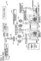
- FIG. 1 a detailed diagram of a prior art exemplary embodiment of a dry gas seal (DGS) system 100 for a carbon dioxide (CO 2 ) pump is presented. It should be noted in the exemplary embodiment that any fluid in a supercritical state can be used as a barrier fluid in place of the exemplary carbon dioxide (CO 2 ).
- DGS dry gas seal
- the exemplary embodiment reflects the behavior of the dry gas seal during operating conditions and includes a CO 2 pump 102 with its associated area to be sealed, a primary (inboard) seal 104 of a dry gas seal, a secondary (outboard) seal 106 of the dry gas seal, a process fluid filter 108, a process fluid heater 110, a valve and control element 112 for controlling the flow to a flare-safe area, an intermediate buffer gas filter 114, intermediate buffer gas 116, barrier fluid 118, pressure reduction valve 120, a primary dry gas seal chamber 122 and a secondary dry gas seal chamber 124.
- this exemplary prior art embodiment depicts process fluid, e.g. carbon dioxide, from the pump discharge being used as a barrier fluid.
- the pressure of the barrier fluid is reduced by a valve 120 and heated by a heater 110.
- the barrier fluid is filtered by filters 108 and injected into the primary dry gas seal chamber 122.
- the pressure of the barrier fluid is higher than the suction pressure of the pump and therefore prevents the entry of any untreated process gas into the primary seal 104.
- the carbon dioxide (CO 2 ) barrier fluid flows partly into the pump through the inner labyrinth and partly to the primary vent through the primary dry gas seal.
- the carbon dioxide (CO 2 ) that flows into the pump reaches a suction pressure that is higher than the critical pressure for carbon dioxide (CO 2 ) and accordingly will not experience icing or flushing.
- the carbon dioxide (CO 2 ) that flows through the primary seal to the primary vent expands from P1 to a value established by the buffer gas (typically N 2 /air at 4-7 bar).
- the temperature of the carbon dioxide (CO 2 ) barrier fluid must be maintained, by a heater, to a value high enough to avoid, during the expansion, the risk of icing or flushing.
- an intermediate buffer gas 116 e.g. nitrogen or dry air is filtered by filters 114 and injected into the secondary dry gas seal chamber 124.
- gases other than nitrogen or air are usable as a buffer gas.
- the pressure of the intermediate buffer gas 116 is higher than the pressure of the barrier gas passing through the primary seal 104 and prevents the barrier gas from reaching the secondary seal 106.
- the mixture of barrier gas 118 and intermediate buffer gas 116 in the secondary dry gas seal chamber 124 passes through a valve 112 and flows to a flare-safe area.
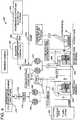
- FIG. 2 a detailed diagram of a prior art exemplary embodiment of a dry gas seal (DGS) system 200 for a carbon dioxide (CO 2 ) pump is presented.
- the prior art exemplary embodiment reflects the behavior of the dry gas seal during a transient, e.g.
- a CO 2 pump 202 with its associated area to be sealed, a primary (inboard) seal 204 of a dry gas seal, a secondary (outboard) seal 206 of the dry gas seal, a process fluid filter 208, a process fluid heater 210, a valve and control element 212 for controlling the flow to a flare-safe area, an intermediate buffer gas filter 214, intermediate buffer gas 216, barrier fluid 218, pressure reduction valve 220, a primary dry gas seal chamber 222 and a secondary dry gas seal chamber 224.
- the CO 2 pump is in a standstill condition and accordingly the discharge pressure from the pump is equal to the pressure in the area to be sealed 202.
- the pressure into the pump reaches a uniform value very close to the suction pressure, know as "settle out pressure".
- the result of the standstill condition is the process fluid from the pump discharge can no longer act as a barrier fluid to prevent the flow of untreated process fluid, from the area to be sealed 202, into the primary seal 204.
- the untreated process fluid is not heated or filtered and therefore contaminates can enter the primary seal 204 and icing can occur in the primary seal 204.
- the pressure of the untreated process fluid is greater than the pressure of the intermediate buffer gas 216 therefore the intermediate buffer gas 216 cannot prevent the flow of untreated process fluid through the primary gas seal 204.
- a detailed diagram of an exemplary embodiment of a dry gas seal (DGS) system 300 for a carbon dioxide (CO 2 ) pump is presented.
- the exemplary embodiment reflects the behavior of the dry gas seal during a operating, e.g.
- a CO 2 pump 302 with its associated area to be sealed, a primary (inboard) seal 304 of a dry gas seal, a secondary (outboard) seal 306 of the dry gas seal, a flare valve 312, and a control element for controlling the flow to a flare-safe area, an intermediate buffer gas filter 314, intermediate buffer gas 316, barrier fluid 318, a primary dry gas seal chamber 322, a secondary dry gas seal chamber 324, a booster compressor 326 and, a booster compressor 326 discharge valve 328, a booster compressor 326 inlet valve 330 and a booster compressor 326 bypass valve 332.
- the pressure in the area to be sealed 302 is lower than the pressure of the barrier fluid 318, provided from the pump discharge, and while the barrier fluid pressure is higher than the pressure of the area to be sealed, flare valve 312 and booster compressor 326 bypass valve 332 are open, booster compressor 326 discharge valve 328 and booster compressor 326 inlet valve 330 are closed and booster compressor 326 is deactivated.
- the pressure of the barrier fluid does not allow the process fluid to flow through the primary seal 304 and prevents contamination and icing of the primary seal 304.
- FIG. 4 a detailed diagram of an exemplary embodiment of a dry gas seal (DGS) system 400 for a carbon dioxide (CO 2 ) pump is presented.
- the exemplary embodiment reflects the behavior of the dry gas seal during a transient, e.g.
- a CO 2 pump 402 with its associated area to be sealed, a primary (inboard) seal 404 of a dry gas seal, a secondary (outboard) seal 406 of the dry gas seal, a valve 412, and control element, for controlling the flow to a flare-safe area, an intermediate buffer gas filter 414, intermediate buffer gas 416, barrier fluid 418, a primary dry gas seal chamber 422, a secondary dry gas seal chamber 424, a booster compressor 426, a booster compressor 426 discharge valve 428, a booster compressor 426 inlet valve 430 and a booster compressor 426 bypass valve 432.
- the pressure into the pump is uniform and is equal to the settle out pressure value and can no longer be used as a barrier fluid.
- the flare valve 412 and the booster compressor 426 bypass valve 432 is closed, the booster compressor 426 discharge valve 428 and the booster compressor 426 inlet valve 430 is opened and the booster compressor 426 is activated.
- the booster compressor raises the pressure of the intermediate buffer gas 416, injected into the secondary dry gas seal chamber 424, to a predetermined pressure (P3) just below the pressure in the area to be sealed 402.
- the increased pressure of the intermediate buffer gas reduces the flow of process gas through the primary seal 404 and prevents contamination and icing of the primary seal 404.
- the exemplary embodiment booster compressor 426 operates in a discontinuous fashion, performing ON/OFF cycles. Next, the exemplary embodiment booster compressor 426 is turned on and the pressure into the secondary seal chamber 424 rises until it reaches the pressure P3 and the booster compressor 426 is turned off. The exemplary embodiment continues with the pressure in the secondary seal chamber 424 slowly dropping, because of leakage of buffer gas through the secondary seal 406.
- the booster compressor 426 when the pressure in the chamber 424 between the primary seal 404 and the secondary seal 406 drops below a predetermined value (P3 - dP3), the booster compressor 426 is turned on. Further, it should be noted in the exemplary embodiment that when the pump returns to operating conditions and barrier fluid 418 pressure rises above the pressure in the area to be sealed 402 the booster compressor 426 is finally turned off.
- a pressure-enthalpy diagram 500 illustrated is the pressure reduction of the barrier fluid through the control valve 120, the temperature rise of the barrier fluid through the heater 110 and the expansion of the treated leakage flow through the primary seal to the primary vent with the pump in running condition.
- the temperature in the exemplary embodiment is high enough to avoid flushing and icing during the expansion.
- a carbon dioxide pressure-enthalpy diagram 600 of a prior art exemplary embodiment dry gas seal system in a standstill operating condition is presented.
- the prior art exemplary embodiment illustrates the pressure difference 602 occurring through the primary seal 604 during a standstill condition.
- the enthalpy diagram 600 depicts the expansion 604 of the untreated carbon dioxide leakage flow through the primary seal and crossing the triple point 606 and the bi-phase zones of the diagram for carbon dioxide. Accordingly, the prior art exemplary embodiment indicates that icing will occur in and around the primary seal and will lead to premature failure of the primary seal.
- FIG. 7 an exemplary embodiment of a carbon dioxide pressure - enthalpy diagram 700 of a dry gas seal system in a standstill operating condition is presented.
- the exemplary embodiment illustrates the pressure difference 702 occurring through the primary seal during a standstill condition.
- the enthalpy diagram 700 depicts the expansion 704 of the untreated carbon dioxide leakage flow through the primary seal and not crossing the triple point 706 and neither bi-phase zone of the diagram for carbon dioxide. Accordingly, the exemplary embodiment indicates that icing will not occur in and around the primary seal.
- an exemplary method embodiment 800 for assuring a safe working condition of the dry gas seal and preventing flushing and/or icing when the pump or compressor is in a standstill condition is depicted.
- the pressure of the barrier fluid in the chamber upstream of the primary seal is measured.
- the measured barrier fluid pressure is compared to a preconfigured value and an indication is generated if the measured barrier fluid pressure is below the preconfigured value.
- step 804 if the indication is presented that the barrier fluid pressure is below the preconfigured value then a valve associated with the dry gas seal and a flare-safe area is closed.
- the valve prevents the exit of any gas from the chamber between the primary seal and the secondary seal except by passing through the secondary seal.
- closing the valve reduces the volume of intermediate buffer gas required to maintain the desired pressure.
- the intermediate buffer gas can be, but is not limited to, Nitrogen or dry air.
- a booster compressor is started to boost the pressure of the intermediate buffer gas injected into the chamber between the primary seal and the secondary seal.
- the booster compressor is operated to maintain the pressure based on a preconfigured value for the chamber pressure that is near the value of the pressure of the process fluid in the area to be sealed by the dry gas seal.
- the preconfigured value can dynamically change based on changes in the pressure of the process fluid in the area to be sealed by the dry gas seal.
- the process fluid can be, but is not limited to, carbon dioxide.
- step 808 the rise in pressure in the chamber between the primary seal and the secondary seal is monitored until the pressure reaches a specified pressure (P3).
- step 810 of the exemplary method embodiment when the pressure reaches pressure P3, the booster compressor is turned off.
- step 812 of the exemplary method embodiment the pressure is monitored until it falls to a lower specified threshold and the method returns to step 806 and restarts the booster compressor. It should be noted that the exemplary method embodiment continues to cycle in this fashion until the pump/compressor returns to a running condition.
- the disclosed exemplary embodiments provide a system and a method for protecting a dry gas seal from at least icing conditions brought on by process fluid expanding through the primary seal of a dry gas seal. It should be understood that this description is not intended to limit the invention. On the contrary, the exemplary embodiments are intended to cover alternatives, modifications and equivalents, which are included in the scope of the invention as defined by the appended claims. Further, in the detailed description of the exemplary embodiments, numerous specific details are set forth in order to provide a comprehensive understanding of the claimed invention. However, one skilled in the art would understand that various embodiments may be practiced without such specific details.
Landscapes
- Engineering & Computer Science (AREA)
- General Engineering & Computer Science (AREA)
- Mechanical Engineering (AREA)
- Structures Of Non-Positive Displacement Pumps (AREA)
- Compressor (AREA)
- Filling Or Discharging Of Gas Storage Vessels (AREA)
- Gasket Seals (AREA)
- Sealing Using Fluids, Sealing Without Contact, And Removal Of Oil (AREA)
- Control Of Positive-Displacement Pumps (AREA)
Description
- The present invention relates generally to dry gas seals for compressors, pumps and, more specifically, to protect the integrity of the primary dry gas seal during standstill conditions.
-
EP 1 326 037 A1 discloses an axis seal device according to the preamble ofclaim 1 provided between a vessel filled with a gas and a rotation axis passing through the vessel. - The application of dry gas seals to centrifugal compressor shaft sealing has dramatically increased in recent years for many reasons. The benefits offered by the use of dry gas seals on a centrifugal compressor include improved compressor reliability and the associated reduction of unscheduled downtime, elimination of seal oil leaking into the compressor and the associated process contamination, elimination of process gas contaminating the seal oil and requiring sour seal oil reclamation through degassing tanks, elimination of costs for replacement and disposal of sour seal oil, reduction of operating costs based on the greater efficiency of a dry gas seal, the reduction of maintenance costs for the simpler dry gas seal system and the reduction of process gas emissions.
- Dry gas seal installation is also adoptable for centrifugal pumps associated with liquefied gas. The many benefits of dry gas seals at the running conditions of centrifugal compressors and pumps mask problems associated with the use of dry gas seals on centrifugal compressors and pumps at other operating conditions such as the transient times of startup, shutdown and low-speed idle. The reason dry gas seals are problematic at these times is based on the requirement of a higher than suction pressure barrier gas to prevent contamination of the dry gas seal with particulate or liquid materials. The contamination can arrive, for example, from the untreated process gas or from bearing lubrication oil.
- A typical centrifugal compressor utilizing a dry gas seal will divert a portion of the process gas from the high-pressure discharge of the compressor then filter, dry and reduce the pressure of the gas. The clean and dry barrier gas is then injected upstream of the primary seal at a pressure slightly greater than the suction pressure of the compressor. The higher pressure barrier gas prevents the untreated process gas from entering the dry gas seal where contaminates can infiltrate the tight tolerances of the rotating dry gas seal surfaces and cause premature dry gas seal ring failure.
- During transient times of operation, the pressure of the process gas from the discharge of the compressor is reduced to the point where it is equal to the suction pressure of the compressor. Consequently, it is no longer possible to use the flow from the discharge of the compressor as a barrier fluid. Upstream of the primary seal, in the seal chamber, there is a pressure very close to the suction pressure of the compressor or pump. Downstream of the primary seal there is a pressure established by a buffer fluid, typically nitrogen or air available at a pressure of four to seven bar. Further, the higher pressure and un-treated process gas permeates the primary dry gas seal, transporting particulate and liquid contamination. This problem is emphasized with carbon dioxide (CO2) as the process flow. The carbon dioxide (CO2) expansion through the tight tolerances of the dry gas seal rings can form ice on the seal rings. Subsequently, when the compressor returns to normal operating conditions, the contamination between the dry gas seal rings results in premature wear and failure of the dry gas seal.
- Prior attempts to resolve this problem have centered on providing a booster for the process fluid to maintain the barrier gas at the conditions provided during normal operation of the compressor or pump. This solution requires the similar treatment of the process fluid with respect to filtering and heating to prevent contamination of the dry gas seal. Accordingly, market pressure is building for a system and method for preventing the backflow of process fluid, and the associated contaminates, through the dry gas seal during transient operating conditions.
- The present invention is defined in the accompanying claims.
- Systems and methods according to these exemplary embodiment descriptions address the above described needs by providing a small secondary compressor for boosting the pressure of an intermediate buffer gas during operating conditions (i.e., startup, shutdown and low-speed idle) when the fluid pressure from the discharge of the pump is equal to the suction pressure of the area to be sealed by the dry gas seal. A simple control system detects a drop in barrier gas pressure in the dry gas seal (i.e., the trigger signal could be but is not limited to simply the "no running" condition of the turbomachinery) and protects the dry gas seal from icing by closing a valve between the dry gas seal and a flare-safe area and starting the secondary compressor to boost the intermediate buffer gas to a preconfigured pressure based on the pressure of the process fluid in the area to be sealed by the dry gas seal.
- According to an exemplary embodiment of a system for assuring a safe working condition of a dry gas seal during standstill operations, a barrier fluid pressure measuring system detects a drop in barrier fluid pressure. The exemplary embodiment continues with a valve connecting the chamber between primary and secondary seal with the flare. Further, the exemplary embodiment continues with a booster compressor for boosting the pressure of an intermediate buffer gas injected into the chamber between the primary and secondary seal. Next the exemplary embodiment comprises a control system for operating the booster compressor based on the measured pressure between the primary and secondary seal.
- According to another exemplary embodiment, a method for assuring a safe working condition of a dry gas seal installed on a liquefied gas pump when the pump is in a transient operating condition, is presented. Continuing with the first step of the exemplary method embodiment, the method detects the barrier gas pressure below a preconfigured value. In the next step of the exemplary method embodiment, the method closes a valve connected to the dry gas seal. Further in the exemplary method embodiment, starting a booster compressor associated with an intermediate buffer gas and maintaining said chamber pressure at a preconfigured value.
- In a further exemplary embodiment, a liquefied gas pump dry gas seal protection system is described. The exemplary embodiment includes a means to detect when the pressure of the barrier fluid drops below a lower limit. The exemplary embodiment further includes a means to regulate the flow from the dry gas seal to a flare-safe area. Continuing with the exemplary embodiment, included is a means to increase the pressure of an intermediate buffer gas injected into the dry gas seal. Continuing with the exemplary embodiment, included is a means to measure the pressure of the buffer gas. Next in the exemplary embodiment, a means to control the means to regulate flow and means to increase pressure based on the means to measure pressure and a preconfigured pressure value.
- The accompanying drawings illustrate exemplary embodiments, wherein:
-
Figure 1 depicts a prior art cross-section view of a dry gas seal and the associated gas support system in an operating condition; -
Figure 2 depicts a prior art cross-section view of a dry gas seal and the associated gas support system in a standstill condition; -
Figure 3 depicts an exemplary embodiment cross-section view of a dry gas seal and the associated gas support system in an operating condition; -
Figure 4 depicts an exemplary embodiment cross-section view of a dry gas seal and the associated gas support system in a standstill condition; -
Figure 5 depicts an exemplary embodiment pressure-enthalpy diagram illustrating the gas leakage flow through the primary dry gas seal when the pump is in the operating condition; -
Figure 6 depicts a prior art pressure-enthalpy diagram illustrating the gas leakage flow through the primary dry gas seal when the pump is in the standstill condition; -
Figure 7 depicts an exemplary embodiment pressure-enthalpy diagram illustrating the gas leakage flow through the primary dry gas seal when the pump is in the standstill condition; and -
Figure 8 is a flowchart depicting a method for maintaining sufficient pressure in the chamber between the primary and secondary dry gas seal to prevent contamination of the primary dry gas seal. - The following detailed description of exemplary embodiments refers to the accompanying drawings. The same reference numbers in different drawings identify the same or similar elements. Also, the following detailed description does not limit the invention. Instead, the scope of the invention is defined by the appended claims.
- Looking to
FIG. 1 , a detailed diagram of a prior art exemplary embodiment of a dry gas seal (DGS)system 100 for a carbon dioxide (CO2) pump is presented. It should be noted in the exemplary embodiment that any fluid in a supercritical state can be used as a barrier fluid in place of the exemplary carbon dioxide (CO2). The exemplary embodiment reflects the behavior of the dry gas seal during operating conditions and includes a CO2 pump 102 with its associated area to be sealed, a primary (inboard)seal 104 of a dry gas seal, a secondary (outboard)seal 106 of the dry gas seal, aprocess fluid filter 108, aprocess fluid heater 110, a valve andcontrol element 112 for controlling the flow to a flare-safe area, an intermediatebuffer gas filter 114,intermediate buffer gas 116,barrier fluid 118,pressure reduction valve 120, a primary drygas seal chamber 122 and a secondary drygas seal chamber 124. - In general, this exemplary prior art embodiment depicts process fluid, e.g. carbon dioxide, from the pump discharge being used as a barrier fluid. The pressure of the barrier fluid is reduced by a
valve 120 and heated by aheater 110. Continuing with the exemplary prior art embodiment, the barrier fluid is filtered byfilters 108 and injected into the primary drygas seal chamber 122. In the exemplary embodiment, the pressure of the barrier fluid is higher than the suction pressure of the pump and therefore prevents the entry of any untreated process gas into theprimary seal 104. - Continuing with the exemplary embodiment, the carbon dioxide (CO2) barrier fluid flows partly into the pump through the inner labyrinth and partly to the primary vent through the primary dry gas seal. Next in the exemplary embodiment, the carbon dioxide (CO2) that flows into the pump reaches a suction pressure that is higher than the critical pressure for carbon dioxide (CO2) and accordingly will not experience icing or flushing. Further in the exemplary embodiment, the carbon dioxide (CO2) that flows through the primary seal to the primary vent expands from P1 to a value established by the buffer gas (typically N2/air at 4-7 bar). It should be noted in the exemplary embodiment that the temperature of the carbon dioxide (CO2) barrier fluid must be maintained, by a heater, to a value high enough to avoid, during the expansion, the risk of icing or flushing.
- Continuing with the exemplary embodiment, an
intermediate buffer gas 116, e.g. nitrogen or dry air is filtered byfilters 114 and injected into the secondary drygas seal chamber 124. It should be noted in the exemplary embodiment that gases other than nitrogen or air are usable as a buffer gas. In the exemplary embodiment, the pressure of theintermediate buffer gas 116 is higher than the pressure of the barrier gas passing through theprimary seal 104 and prevents the barrier gas from reaching thesecondary seal 106. In the exemplary embodiment, the mixture ofbarrier gas 118 andintermediate buffer gas 116 in the secondary drygas seal chamber 124 passes through avalve 112 and flows to a flare-safe area. - Looking now to
FIG. 2 , a detailed diagram of a prior art exemplary embodiment of a dry gas seal (DGS)system 200 for a carbon dioxide (CO2) pump is presented. The prior art exemplary embodiment reflects the behavior of the dry gas seal during a transient, e.g. standstill, condition and includes a CO2 pump 202 with its associated area to be sealed, a primary (inboard)seal 204 of a dry gas seal, a secondary (outboard)seal 206 of the dry gas seal, aprocess fluid filter 208, aprocess fluid heater 210, a valve and control element 212 for controlling the flow to a flare-safe area, an intermediatebuffer gas filter 214,intermediate buffer gas 216,barrier fluid 218,pressure reduction valve 220, a primary drygas seal chamber 222 and a secondary drygas seal chamber 224. - Continuing with the prior art exemplary embodiment, the CO2 pump is in a standstill condition and accordingly the discharge pressure from the pump is equal to the pressure in the area to be sealed 202. When the pump is in a standstill condition, the pressure into the pump reaches a uniform value very close to the suction pressure, know as "settle out pressure". It should be noted in the prior art exemplary embodiment that the result of the standstill condition is the process fluid from the pump discharge can no longer act as a barrier fluid to prevent the flow of untreated process fluid, from the area to be sealed 202, into the
primary seal 204. Further in the prior art exemplary embodiment, the untreated process fluid is not heated or filtered and therefore contaminates can enter theprimary seal 204 and icing can occur in theprimary seal 204. It should also be noted in the prior art exemplary embodiment that the pressure of the untreated process fluid is greater than the pressure of theintermediate buffer gas 216 therefore theintermediate buffer gas 216 cannot prevent the flow of untreated process fluid through theprimary gas seal 204. - Continuing with
FIG. 3 , a detailed diagram of an exemplary embodiment of a dry gas seal (DGS)system 300 for a carbon dioxide (CO2) pump is presented. The exemplary embodiment reflects the behavior of the dry gas seal during a operating, e.g. running, condition and includes a CO2 pump 302 with its associated area to be sealed, a primary (inboard)seal 304 of a dry gas seal, a secondary (outboard)seal 306 of the dry gas seal, aflare valve 312, and a control element for controlling the flow to a flare-safe area, an intermediatebuffer gas filter 314,intermediate buffer gas 316,barrier fluid 318, a primary drygas seal chamber 322, a secondary drygas seal chamber 324, abooster compressor 326 and, abooster compressor 326discharge valve 328, abooster compressor 326inlet valve 330 and abooster compressor 326bypass valve 332. - In a non-limiting exemplary embodiment, while the pump is in a running condition, the pressure in the area to be sealed 302 is lower than the pressure of the
barrier fluid 318, provided from the pump discharge, and while the barrier fluid pressure is higher than the pressure of the area to be sealed,flare valve 312 andbooster compressor 326bypass valve 332 are open,booster compressor 326discharge valve 328 andbooster compressor 326inlet valve 330 are closed andbooster compressor 326 is deactivated. Continuing with the exemplary embodiment, the pressure of the barrier fluid does not allow the process fluid to flow through theprimary seal 304 and prevents contamination and icing of theprimary seal 304. - Looking now to
FIG. 4 , a detailed diagram of an exemplary embodiment of a dry gas seal (DGS)system 400 for a carbon dioxide (CO2) pump is presented. The exemplary embodiment reflects the behavior of the dry gas seal during a transient, e.g. standstill, condition and includes a CO2 pump 402 with its associated area to be sealed, a primary (inboard)seal 404 of a dry gas seal, a secondary (outboard)seal 406 of the dry gas seal, avalve 412, and control element, for controlling the flow to a flare-safe area, an intermediatebuffer gas filter 414,intermediate buffer gas 416,barrier fluid 418, a primary drygas seal chamber 422, a secondary drygas seal chamber 424, abooster compressor 426, abooster compressor 426discharge valve 428, abooster compressor 426inlet valve 430 and abooster compressor 426bypass valve 432. - In a non-limiting exemplary embodiment, in "no running" conditions of the pump or compressor (trip, shutdown, startup, pressurized standstill, etc.), the pressure into the pump is uniform and is equal to the settle out pressure value and can no longer be used as a barrier fluid. In this exemplary embodiment condition, the
flare valve 412 and thebooster compressor 426bypass valve 432 is closed, thebooster compressor 426discharge valve 428 and thebooster compressor 426inlet valve 430 is opened and thebooster compressor 426 is activated. It should be noted in the exemplary embodiment that the booster compressor raises the pressure of theintermediate buffer gas 416, injected into the secondary drygas seal chamber 424, to a predetermined pressure (P3) just below the pressure in the area to be sealed 402. Continuing with the exemplary embodiment, the increased pressure of the intermediate buffer gas reduces the flow of process gas through theprimary seal 404 and prevents contamination and icing of theprimary seal 404. The exemplaryembodiment booster compressor 426 operates in a discontinuous fashion, performing ON/OFF cycles. Next, the exemplaryembodiment booster compressor 426 is turned on and the pressure into thesecondary seal chamber 424 rises until it reaches the pressure P3 and thebooster compressor 426 is turned off. The exemplary embodiment continues with the pressure in thesecondary seal chamber 424 slowly dropping, because of leakage of buffer gas through thesecondary seal 406. Continuing with the exemplary embodiment, when the pressure in thechamber 424 between theprimary seal 404 and thesecondary seal 406 drops below a predetermined value (P3 - dP3), thebooster compressor 426 is turned on. Further, it should be noted in the exemplary embodiment that when the pump returns to operating conditions andbarrier fluid 418 pressure rises above the pressure in the area to be sealed 402 thebooster compressor 426 is finally turned off. - Turning now to
FIG. 5 , in a pressure-enthalpy diagram 500 illustrated is the pressure reduction of the barrier fluid through thecontrol valve 120, the temperature rise of the barrier fluid through theheater 110 and the expansion of the treated leakage flow through the primary seal to the primary vent with the pump in running condition. The temperature in the exemplary embodiment is high enough to avoid flushing and icing during the expansion. - Continuing now to
FIG. 6 , a carbon dioxide pressure-enthalpy diagram 600 of a prior art exemplary embodiment dry gas seal system in a standstill operating condition is presented. The prior art exemplary embodiment illustrates thepressure difference 602 occurring through theprimary seal 604 during a standstill condition. In another aspect of the prior art exemplary embodiment, the enthalpy diagram 600 depicts theexpansion 604 of the untreated carbon dioxide leakage flow through the primary seal and crossing thetriple point 606 and the bi-phase zones of the diagram for carbon dioxide. Accordingly, the prior art exemplary embodiment indicates that icing will occur in and around the primary seal and will lead to premature failure of the primary seal. - Looking now to
FIG. 7 , an exemplary embodiment of a carbon dioxide pressure - enthalpy diagram 700 of a dry gas seal system in a standstill operating condition is presented. The exemplary embodiment illustrates the pressure difference 702 occurring through the primary seal during a standstill condition. In another aspect of the exemplary embodiment, the enthalpy diagram 700 depicts theexpansion 704 of the untreated carbon dioxide leakage flow through the primary seal and not crossing thetriple point 706 and neither bi-phase zone of the diagram for carbon dioxide. Accordingly, the exemplary embodiment indicates that icing will not occur in and around the primary seal. - Continuing now to
FIG. 8 , anexemplary method embodiment 800 for assuring a safe working condition of the dry gas seal and preventing flushing and/or icing when the pump or compressor is in a standstill condition is depicted. Starting at exemplarymethod embodiment step 802, the pressure of the barrier fluid in the chamber upstream of the primary seal is measured. In this exemplary method embodiment, the measured barrier fluid pressure is compared to a preconfigured value and an indication is generated if the measured barrier fluid pressure is below the preconfigured value. - Next at exemplary
method embodiment step 804, if the indication is presented that the barrier fluid pressure is below the preconfigured value then a valve associated with the dry gas seal and a flare-safe area is closed. In one aspect of the exemplary method embodiment, the valve prevents the exit of any gas from the chamber between the primary seal and the secondary seal except by passing through the secondary seal. In another aspect of the exemplary method embodiment, closing the valve reduces the volume of intermediate buffer gas required to maintain the desired pressure. Further in the exemplary method embodiment, the intermediate buffer gas can be, but is not limited to, Nitrogen or dry air. - Next at exemplary method embodiment step 806, a booster compressor is started to boost the pressure of the intermediate buffer gas injected into the chamber between the primary seal and the secondary seal. In another aspect of the exemplary method embodiment, the booster compressor is operated to maintain the pressure based on a preconfigured value for the chamber pressure that is near the value of the pressure of the process fluid in the area to be sealed by the dry gas seal. Continuing with the exemplary method embodiment, the preconfigured value can dynamically change based on changes in the pressure of the process fluid in the area to be sealed by the dry gas seal. It should be noted in the exemplary method embodiment that the process fluid can be, but is not limited to, carbon dioxide.
- Continuing with the exemplary method embodiment, at
step 808 the rise in pressure in the chamber between the primary seal and the secondary seal is monitored until the pressure reaches a specified pressure (P3). Next, atstep 810 of the exemplary method embodiment, when the pressure reaches pressure P3, the booster compressor is turned off. Further, atstep 812 of the exemplary method embodiment, the pressure is monitored until it falls to a lower specified threshold and the method returns to step 806 and restarts the booster compressor. It should be noted that the exemplary method embodiment continues to cycle in this fashion until the pump/compressor returns to a running condition. - The disclosed exemplary embodiments provide a system and a method for protecting a dry gas seal from at least icing conditions brought on by process fluid expanding through the primary seal of a dry gas seal. It should be understood that this description is not intended to limit the invention. On the contrary, the exemplary embodiments are intended to cover alternatives, modifications and equivalents, which are included in the scope of the invention as defined by the appended claims. Further, in the detailed description of the exemplary embodiments, numerous specific details are set forth in order to provide a comprehensive understanding of the claimed invention. However, one skilled in the art would understand that various embodiments may be practiced without such specific details.
- This written description uses examples of the subject matter disclosed to enable any person skilled in the art to practice the same, including making and using any devices or systems and performing any incorporated methods. The patentable scope of the subject matter is defined by the claims, and may include other examples that occur to those skilled in the art. Such other examples are intended to be within the scope of the claims.
Claims (10)
- A system for assuring a safe working condition of a dry gas seal, associated with a pump or compressor, during standstill operating conditions, the system comprising:
a controllable valve (412) connected to a chamber between a primary seal and a secondary seal of said dry gas seal, said valve associated with a vent to a flare-safe area;
a compressor (426) configured for boosting the pressure of an intermediate buffer gas injected into said chamber; and characterized by
a barrier fluid pressure detector for determining when barrier fluid pressure drops below a preconfigured lower limit and when said pump or compressor, at said standstill operating condition is pressurized at a settle-out pressure; and by
a control system configured for operating said controllable valve (412) and said compressor (426) based on said barrier fluid pressure. - The system of claim 1, wherein said controllable valve (412) is associated with a flare line connected to said dry gas seal.
- The system of claim 1 or claim 2, wherein said barrier fluid is carbon dioxide.
- The system of any preceding claim, wherein said intermediate buffer gas is Nitrogen.
- The system of any preceding claim, wherein said intermediate buffer gas is dry air.
- The system of any preceding claim, wherein said compressor (426) boosts said intermediate buffer gas pressure to a preconfigured pressure when said barrier fluid pressure drops below said preconfigured pressure.
- The system of any preceding claim, wherein said buffer gas preconfigured pressure is less than a pressure of an area to be sealed associated with said dry gas seal.
- The system of any preceding claim, wherein said buffer gas preconfigured pressure is greater than a pressure of an area to be sealed associated with said dry gas seal.
- The system of any preceding claim, wherein the pressure detector is arranged to measure pressure in a chamber (424) between a primary and a secondary seal (404,406).
- A method for assuring a safe working condition of a dry gas seal associated with a liquefied gas pump or compressor when said liquefied gas pump or compressor is in a transient operating condition, said method comprising:detecting a barrier fluid pressure below a preconfigured value with a barrier fluid pressure detector for determining when barrier fluid pressure drops below a preconfigured lower limit and when said pump or compressor, at said standstill operating condition is pressurized at a settle-out pressure;closing a valve connected to said dry gas seal; andstarting a compressor associated with an intermediate buffer gas and maintaining said buffer gas pressure at said preconfigured value;wherein a control system is configured for operating said controllable valve (412) and said compressor (426) based on said barrier fluid pressure.
Applications Claiming Priority (2)
| Application Number | Priority Date | Filing Date | Title |
|---|---|---|---|
| IT000057A ITCO20110057A1 (en) | 2011-12-05 | 2011-12-05 | DRY GAS SEAL FOR HIGH PRESSURE PUMP BUFFER FOR SUPERCRITIC CO2 |
| PCT/EP2012/073720 WO2013083437A1 (en) | 2011-12-05 | 2012-11-27 | Dry gas seal for supercritical co2 pump-high pressure buffer |
Publications (2)
| Publication Number | Publication Date |
|---|---|
| EP2805024A1 EP2805024A1 (en) | 2014-11-26 |
| EP2805024B1 true EP2805024B1 (en) | 2017-03-15 |
Family
ID=45571624
Family Applications (1)
| Application Number | Title | Priority Date | Filing Date |
|---|---|---|---|
| EP12790924.0A Revoked EP2805024B1 (en) | 2011-12-05 | 2012-11-27 | Dry gas seal for supercritical co2 pump-high pressure buffer |
Country Status (10)
| Country | Link |
|---|---|
| US (1) | US20140321972A1 (en) |
| EP (1) | EP2805024B1 (en) |
| JP (1) | JP6231990B2 (en) |
| KR (1) | KR102068734B1 (en) |
| CN (1) | CN103958836B (en) |
| AU (1) | AU2012348706B9 (en) |
| BR (1) | BR112014012755B8 (en) |
| CA (1) | CA2856782C (en) |
| IT (1) | ITCO20110057A1 (en) |
| WO (1) | WO2013083437A1 (en) |
Families Citing this family (18)
| Publication number | Priority date | Publication date | Assignee | Title |
|---|---|---|---|---|
| US9624785B2 (en) | 2014-01-24 | 2017-04-18 | Solar Turbines Incorporated | System for monitoring health of a seal |
| DE102014203464A1 (en) | 2014-02-26 | 2015-08-27 | Siemens Aktiengesellschaft | Plant with a gas seal, method of operation |
| DE102014208738B3 (en) * | 2014-05-09 | 2015-11-26 | Eagleburgmann Germany Gmbh & Co. Kg | Mechanical seal assembly with improved gas separation |
| DE102014211690A1 (en) | 2014-06-18 | 2015-12-24 | Siemens Aktiengesellschaft | Fluid energy machine, method of operation |
| DE102014011042A1 (en) * | 2014-07-26 | 2016-01-28 | Man Diesel & Turbo Se | flow machine |
| JP6468859B2 (en) * | 2015-01-23 | 2019-02-13 | 三菱重工コンプレッサ株式会社 | Rotating machine system |
| ITUB20152842A1 (en) * | 2015-08-04 | 2017-02-04 | Nuovo Pignone Tecnologie Srl | Pumping system equipped with a barrier fluid supply circuit for dry seals. |
| US11796064B2 (en) | 2016-06-10 | 2023-10-24 | John Crane Uk Limited | Reduced emission gas seal |
| US10247194B2 (en) * | 2016-06-10 | 2019-04-02 | John Crane Uk Ltd. | Reduced emission gas seal |
| US10563663B2 (en) | 2018-04-06 | 2020-02-18 | Solar Turbines Incorporated | Nitrogen purge of compressor dry seal |
| JP7360387B2 (en) * | 2018-07-19 | 2023-10-12 | 株式会社荏原製作所 | Seal system and pump system equipped with the seal system |
| DE102018123728A1 (en) * | 2018-09-26 | 2020-03-26 | Man Energy Solutions Se | Supply system of a sealing system of a turbomachine and turbomachine with a sealing and supply system |
| CN111577400B (en) * | 2020-04-29 | 2024-08-09 | 中国核动力研究设计院 | Supercritical carbon dioxide turbine shaft end sealing method and device for dry gas coupling labyrinth seal |
| CN111911413B (en) * | 2020-06-29 | 2022-06-28 | 西门子工业透平机械(葫芦岛)有限公司 | Dry gas sealing device for compressor |
| IT202000029783A1 (en) * | 2020-12-03 | 2022-06-03 | Nuovo Pignone Tecnologie Srl | SYSTEM FOR RECOVERY OF SEALING GAS LEAKS AND INCREASING THE SEALING GAS PRESSURE, AND METHOD |
| US12435716B2 (en) * | 2022-05-09 | 2025-10-07 | Hoerbiger Wien Gmbh | Pressure packing for a reciprocating piston compressor with buffer gas barrier |
| IT202200023679A1 (en) * | 2022-11-16 | 2023-02-16 | Nuovo Pignone Tecnologie Srl | A MULTISTAGE INLINE COMPRESSOR SYSTEM WITH DRY GAS SEALS AND METHOD |
| US12359674B2 (en) * | 2023-07-06 | 2025-07-15 | Solar Turbines Incorporated | System and method for injecting dry gases into gas compressor |
Citations (8)
| Publication number | Priority date | Publication date | Assignee | Title |
|---|---|---|---|---|
| EP0361844A2 (en) | 1988-09-30 | 1990-04-04 | Nova Corporation Of Alberta | Gas compressor having dry gas seals |
| DE19523713A1 (en) | 1995-06-22 | 1997-01-02 | Mannesmann Ag | Method and device for ensuring the functionality of gas seals in turbocompressors |
| US6345954B1 (en) | 1995-06-23 | 2002-02-12 | Flowserve Management Company | Dry gas seal contamination prevention system |
| EP1207310A1 (en) | 1999-07-23 | 2002-05-22 | Hitachi, Ltd. | Turbo fluid machinery and dry gas seal used for the machinery |
| US6708981B2 (en) | 2000-02-24 | 2004-03-23 | John Crane Uk Limited | Seal assemblies |
| EP1577561A1 (en) | 2004-03-19 | 2005-09-21 | MAN Turbomaschinen AG Schweiz | Device for circulating and heating sealing gas in a centrifugal compressor |
| US20070147988A1 (en) | 2005-12-28 | 2007-06-28 | Hitachi Plant Technologies, Ltd. | Centrifugal compressor and dry gas seal system for use in it |
| WO2010118977A1 (en) | 2009-04-16 | 2010-10-21 | Siemens Aktiengesellschaft | Multi-stage turbo compressor |
Family Cites Families (15)
| Publication number | Priority date | Publication date | Assignee | Title |
|---|---|---|---|---|
| JPS61169602A (en) * | 1985-01-23 | 1986-07-31 | Hitachi Ltd | Turbing land steam pressure control device |
| US5141389A (en) * | 1990-03-20 | 1992-08-25 | Nova Corporation Of Alberta | Control system for regulating the axial loading of a rotor of a fluid machine |
| JP3517710B2 (en) * | 2000-06-29 | 2004-04-12 | 日本ピラー工業株式会社 | Shaft sealing device for liquefied gas |
| JP2002022875A (en) * | 2000-07-10 | 2002-01-23 | Mitsubishi Heavy Ind Ltd | Helium gas turbine power generating system and shaft sealing device |
| US20020077512A1 (en) * | 2000-12-20 | 2002-06-20 | Tendick Rex Carl | Hydrocarbon conversion system and method with a plurality of sources of compressed oxygen-containing gas |
| EP1326037A1 (en) * | 2002-01-03 | 2003-07-09 | Mitsubishi Heavy Industries, Ltd. | Rotation axis seal device and helium gas turbine power generation system using the same |
| US6715985B2 (en) * | 2002-05-15 | 2004-04-06 | John Crane Inc. | Gas conditioning system |
| US20070295402A1 (en) * | 2006-06-21 | 2007-12-27 | General Electric Company | Pressurized gas supply and control system for actuation of active seals in turbomachinery |
| US8651801B2 (en) * | 2008-05-21 | 2014-02-18 | John Crane Inc. | Seal monitoring and control system |
| DE102008048942B4 (en) * | 2008-09-25 | 2011-01-13 | Siemens Aktiengesellschaft | Arrangement with a shaft seal |
| EP2376821B1 (en) * | 2008-12-15 | 2013-07-10 | Flowserve Management Company | Seal leakage gas recovery system |
| JP2010159634A (en) * | 2009-01-06 | 2010-07-22 | Hitachi Ltd | Seal structure of turbo machine |
| IT1399171B1 (en) * | 2009-07-10 | 2013-04-11 | Nuovo Pignone Spa | HIGH PRESSURE COMPRESSION UNIT FOR INDUSTRIAL PLANT PROCESS FLUIDS AND RELATED OPERATING METHOD |
| IT1397059B1 (en) * | 2009-11-23 | 2012-12-28 | Nuovo Pignone Spa | SEAL SYSTEM FOR DRY GAS, LOW EMISSION FOR COMPRESSORS |
| JP5535749B2 (en) * | 2010-04-28 | 2014-07-02 | 三菱重工業株式会社 | Dry gas seal structure |
-
2011
- 2011-12-05 IT IT000057A patent/ITCO20110057A1/en unknown
-
2012
- 2012-11-27 WO PCT/EP2012/073720 patent/WO2013083437A1/en not_active Ceased
- 2012-11-27 CN CN201280060000.XA patent/CN103958836B/en active Active
- 2012-11-27 JP JP2014543863A patent/JP6231990B2/en active Active
- 2012-11-27 EP EP12790924.0A patent/EP2805024B1/en not_active Revoked
- 2012-11-27 KR KR1020147015210A patent/KR102068734B1/en active Active
- 2012-11-27 BR BR112014012755A patent/BR112014012755B8/en active IP Right Grant
- 2012-11-27 CA CA2856782A patent/CA2856782C/en active Active
- 2012-11-27 AU AU2012348706A patent/AU2012348706B9/en active Active
- 2012-11-27 US US14/362,520 patent/US20140321972A1/en not_active Abandoned
Patent Citations (8)
| Publication number | Priority date | Publication date | Assignee | Title |
|---|---|---|---|---|
| EP0361844A2 (en) | 1988-09-30 | 1990-04-04 | Nova Corporation Of Alberta | Gas compressor having dry gas seals |
| DE19523713A1 (en) | 1995-06-22 | 1997-01-02 | Mannesmann Ag | Method and device for ensuring the functionality of gas seals in turbocompressors |
| US6345954B1 (en) | 1995-06-23 | 2002-02-12 | Flowserve Management Company | Dry gas seal contamination prevention system |
| EP1207310A1 (en) | 1999-07-23 | 2002-05-22 | Hitachi, Ltd. | Turbo fluid machinery and dry gas seal used for the machinery |
| US6708981B2 (en) | 2000-02-24 | 2004-03-23 | John Crane Uk Limited | Seal assemblies |
| EP1577561A1 (en) | 2004-03-19 | 2005-09-21 | MAN Turbomaschinen AG Schweiz | Device for circulating and heating sealing gas in a centrifugal compressor |
| US20070147988A1 (en) | 2005-12-28 | 2007-06-28 | Hitachi Plant Technologies, Ltd. | Centrifugal compressor and dry gas seal system for use in it |
| WO2010118977A1 (en) | 2009-04-16 | 2010-10-21 | Siemens Aktiengesellschaft | Multi-stage turbo compressor |
Also Published As
| Publication number | Publication date |
|---|---|
| BR112014012755B1 (en) | 2021-10-05 |
| US20140321972A1 (en) | 2014-10-30 |
| CA2856782C (en) | 2019-11-12 |
| JP6231990B2 (en) | 2017-11-15 |
| BR112014012755A2 (en) | 2017-06-13 |
| AU2012348706B2 (en) | 2016-11-24 |
| BR112014012755A8 (en) | 2021-06-01 |
| CA2856782A1 (en) | 2013-06-13 |
| AU2012348706A1 (en) | 2014-06-12 |
| CN103958836A (en) | 2014-07-30 |
| KR102068734B1 (en) | 2020-01-21 |
| KR20140109375A (en) | 2014-09-15 |
| BR112014012755B8 (en) | 2022-07-05 |
| WO2013083437A1 (en) | 2013-06-13 |
| ITCO20110057A1 (en) | 2013-06-06 |
| EP2805024A1 (en) | 2014-11-26 |
| CN103958836B (en) | 2016-08-31 |
| AU2012348706B9 (en) | 2017-01-19 |
| JP2015501903A (en) | 2015-01-19 |
Similar Documents
| Publication | Publication Date | Title |
|---|---|---|
| EP2805024B1 (en) | Dry gas seal for supercritical co2 pump-high pressure buffer | |
| JP5285147B2 (en) | Seal monitoring and control system | |
| EP2772670B1 (en) | Dry gas seal structure | |
| JP5535749B2 (en) | Dry gas seal structure | |
| CA2674508A1 (en) | Seal chamber conditioning valve for a rotodynamic pump | |
| CN106687663A (en) | Shaft seal, method for operation | |
| US6969229B2 (en) | Sealing system for centrifugal compressors which process lethal gases | |
| JP2000130309A (en) | Water sealing device for hydraulic machine and control method therefor | |
| Leong et al. | Process-Design Considerations for a Compressor Dry-Gas Seal-System Interface | |
| Bhat | Dry Gas Seals. Centrifugal Compressor Shaft End Seals | |
| AU2014240372A1 (en) | Seal monitoring and control system |
Legal Events
| Date | Code | Title | Description |
|---|---|---|---|
| PUAI | Public reference made under article 153(3) epc to a published international application that has entered the european phase |
Free format text: ORIGINAL CODE: 0009012 |
|
| 17P | Request for examination filed |
Effective date: 20140707 |
|
| AK | Designated contracting states |
Kind code of ref document: A1 Designated state(s): AL AT BE BG CH CY CZ DE DK EE ES FI FR GB GR HR HU IE IS IT LI LT LU LV MC MK MT NL NO PL PT RO RS SE SI SK SM TR |
|
| DAX | Request for extension of the european patent (deleted) | ||
| GRAP | Despatch of communication of intention to grant a patent |
Free format text: ORIGINAL CODE: EPIDOSNIGR1 |
|
| INTG | Intention to grant announced |
Effective date: 20161018 |
|
| STAA | Information on the status of an ep patent application or granted ep patent |
Free format text: STATUS: GRANT OF PATENT IS INTENDED |
|
| GRAS | Grant fee paid |
Free format text: ORIGINAL CODE: EPIDOSNIGR3 |
|
| GRAA | (expected) grant |
Free format text: ORIGINAL CODE: 0009210 |
|
| STAA | Information on the status of an ep patent application or granted ep patent |
Free format text: STATUS: THE PATENT HAS BEEN GRANTED |
|
| AK | Designated contracting states |
Kind code of ref document: B1 Designated state(s): AL AT BE BG CH CY CZ DE DK EE ES FI FR GB GR HR HU IE IS IT LI LT LU LV MC MK MT NL NO PL PT RO RS SE SI SK SM TR |
|
| REG | Reference to a national code |
Ref country code: CH Ref legal event code: EP Ref country code: GB Ref legal event code: FG4D |
|
| REG | Reference to a national code |
Ref country code: IE Ref legal event code: FG4D |
|
| REG | Reference to a national code |
Ref country code: AT Ref legal event code: REF Ref document number: 875816 Country of ref document: AT Kind code of ref document: T Effective date: 20170415 |
|
| REG | Reference to a national code |
Ref country code: DE Ref legal event code: R096 Ref document number: 602012029894 Country of ref document: DE |
|
| REG | Reference to a national code |
Ref country code: NL Ref legal event code: FP |
|
| REG | Reference to a national code |
Ref country code: NO Ref legal event code: T2 Effective date: 20170315 |
|
| REG | Reference to a national code |
Ref country code: LT Ref legal event code: MG4D |
|
| PG25 | Lapsed in a contracting state [announced via postgrant information from national office to epo] |
Ref country code: GR Free format text: LAPSE BECAUSE OF FAILURE TO SUBMIT A TRANSLATION OF THE DESCRIPTION OR TO PAY THE FEE WITHIN THE PRESCRIBED TIME-LIMIT Effective date: 20170616 Ref country code: FI Free format text: LAPSE BECAUSE OF FAILURE TO SUBMIT A TRANSLATION OF THE DESCRIPTION OR TO PAY THE FEE WITHIN THE PRESCRIBED TIME-LIMIT Effective date: 20170315 Ref country code: LT Free format text: LAPSE BECAUSE OF FAILURE TO SUBMIT A TRANSLATION OF THE DESCRIPTION OR TO PAY THE FEE WITHIN THE PRESCRIBED TIME-LIMIT Effective date: 20170315 Ref country code: HR Free format text: LAPSE BECAUSE OF FAILURE TO SUBMIT A TRANSLATION OF THE DESCRIPTION OR TO PAY THE FEE WITHIN THE PRESCRIBED TIME-LIMIT Effective date: 20170315 |
|
| REG | Reference to a national code |
Ref country code: AT Ref legal event code: MK05 Ref document number: 875816 Country of ref document: AT Kind code of ref document: T Effective date: 20170315 |
|
| PG25 | Lapsed in a contracting state [announced via postgrant information from national office to epo] |
Ref country code: SE Free format text: LAPSE BECAUSE OF FAILURE TO SUBMIT A TRANSLATION OF THE DESCRIPTION OR TO PAY THE FEE WITHIN THE PRESCRIBED TIME-LIMIT Effective date: 20170315 Ref country code: RS Free format text: LAPSE BECAUSE OF FAILURE TO SUBMIT A TRANSLATION OF THE DESCRIPTION OR TO PAY THE FEE WITHIN THE PRESCRIBED TIME-LIMIT Effective date: 20170315 Ref country code: BG Free format text: LAPSE BECAUSE OF FAILURE TO SUBMIT A TRANSLATION OF THE DESCRIPTION OR TO PAY THE FEE WITHIN THE PRESCRIBED TIME-LIMIT Effective date: 20170615 Ref country code: LV Free format text: LAPSE BECAUSE OF FAILURE TO SUBMIT A TRANSLATION OF THE DESCRIPTION OR TO PAY THE FEE WITHIN THE PRESCRIBED TIME-LIMIT Effective date: 20170315 |
|
| PG25 | Lapsed in a contracting state [announced via postgrant information from national office to epo] |
Ref country code: AT Free format text: LAPSE BECAUSE OF FAILURE TO SUBMIT A TRANSLATION OF THE DESCRIPTION OR TO PAY THE FEE WITHIN THE PRESCRIBED TIME-LIMIT Effective date: 20170315 Ref country code: RO Free format text: LAPSE BECAUSE OF FAILURE TO SUBMIT A TRANSLATION OF THE DESCRIPTION OR TO PAY THE FEE WITHIN THE PRESCRIBED TIME-LIMIT Effective date: 20170315 Ref country code: SK Free format text: LAPSE BECAUSE OF FAILURE TO SUBMIT A TRANSLATION OF THE DESCRIPTION OR TO PAY THE FEE WITHIN THE PRESCRIBED TIME-LIMIT Effective date: 20170315 Ref country code: EE Free format text: LAPSE BECAUSE OF FAILURE TO SUBMIT A TRANSLATION OF THE DESCRIPTION OR TO PAY THE FEE WITHIN THE PRESCRIBED TIME-LIMIT Effective date: 20170315 Ref country code: IT Free format text: LAPSE BECAUSE OF FAILURE TO SUBMIT A TRANSLATION OF THE DESCRIPTION OR TO PAY THE FEE WITHIN THE PRESCRIBED TIME-LIMIT Effective date: 20170315 Ref country code: ES Free format text: LAPSE BECAUSE OF FAILURE TO SUBMIT A TRANSLATION OF THE DESCRIPTION OR TO PAY THE FEE WITHIN THE PRESCRIBED TIME-LIMIT Effective date: 20170315 Ref country code: CZ Free format text: LAPSE BECAUSE OF FAILURE TO SUBMIT A TRANSLATION OF THE DESCRIPTION OR TO PAY THE FEE WITHIN THE PRESCRIBED TIME-LIMIT Effective date: 20170315 |
|
| REG | Reference to a national code |
Ref country code: FR Ref legal event code: PLFP Year of fee payment: 6 |
|
| PG25 | Lapsed in a contracting state [announced via postgrant information from national office to epo] |
Ref country code: IS Free format text: LAPSE BECAUSE OF FAILURE TO SUBMIT A TRANSLATION OF THE DESCRIPTION OR TO PAY THE FEE WITHIN THE PRESCRIBED TIME-LIMIT Effective date: 20170715 Ref country code: PT Free format text: LAPSE BECAUSE OF FAILURE TO SUBMIT A TRANSLATION OF THE DESCRIPTION OR TO PAY THE FEE WITHIN THE PRESCRIBED TIME-LIMIT Effective date: 20170717 Ref country code: SM Free format text: LAPSE BECAUSE OF FAILURE TO SUBMIT A TRANSLATION OF THE DESCRIPTION OR TO PAY THE FEE WITHIN THE PRESCRIBED TIME-LIMIT Effective date: 20170315 Ref country code: PL Free format text: LAPSE BECAUSE OF FAILURE TO SUBMIT A TRANSLATION OF THE DESCRIPTION OR TO PAY THE FEE WITHIN THE PRESCRIBED TIME-LIMIT Effective date: 20170315 |
|
| REG | Reference to a national code |
Ref country code: DE Ref legal event code: R026 Ref document number: 602012029894 Country of ref document: DE |
|
| PLBI | Opposition filed |
Free format text: ORIGINAL CODE: 0009260 |
|
| PLAX | Notice of opposition and request to file observation + time limit sent |
Free format text: ORIGINAL CODE: EPIDOSNOBS2 |
|
| 26 | Opposition filed |
Opponent name: SIEMENS AKTIENGESELLSCHAFT Effective date: 20171215 |
|
| PG25 | Lapsed in a contracting state [announced via postgrant information from national office to epo] |
Ref country code: DK Free format text: LAPSE BECAUSE OF FAILURE TO SUBMIT A TRANSLATION OF THE DESCRIPTION OR TO PAY THE FEE WITHIN THE PRESCRIBED TIME-LIMIT Effective date: 20170315 |
|
| PG25 | Lapsed in a contracting state [announced via postgrant information from national office to epo] |
Ref country code: SI Free format text: LAPSE BECAUSE OF FAILURE TO SUBMIT A TRANSLATION OF THE DESCRIPTION OR TO PAY THE FEE WITHIN THE PRESCRIBED TIME-LIMIT Effective date: 20170315 |
|
| PLBB | Reply of patent proprietor to notice(s) of opposition received |
Free format text: ORIGINAL CODE: EPIDOSNOBS3 |
|
| PG25 | Lapsed in a contracting state [announced via postgrant information from national office to epo] |
Ref country code: MC Free format text: LAPSE BECAUSE OF FAILURE TO SUBMIT A TRANSLATION OF THE DESCRIPTION OR TO PAY THE FEE WITHIN THE PRESCRIBED TIME-LIMIT Effective date: 20170315 |
|
| PG25 | Lapsed in a contracting state [announced via postgrant information from national office to epo] |
Ref country code: LU Free format text: LAPSE BECAUSE OF NON-PAYMENT OF DUE FEES Effective date: 20171127 |
|
| REG | Reference to a national code |
Ref country code: BE Ref legal event code: MM Effective date: 20171130 |
|
| REG | Reference to a national code |
Ref country code: IE Ref legal event code: MM4A |
|
| PG25 | Lapsed in a contracting state [announced via postgrant information from national office to epo] |
Ref country code: MT Free format text: LAPSE BECAUSE OF NON-PAYMENT OF DUE FEES Effective date: 20171127 |
|
| REG | Reference to a national code |
Ref country code: FR Ref legal event code: PLFP Year of fee payment: 7 |
|
| PG25 | Lapsed in a contracting state [announced via postgrant information from national office to epo] |
Ref country code: IE Free format text: LAPSE BECAUSE OF NON-PAYMENT OF DUE FEES Effective date: 20171127 |
|
| PG25 | Lapsed in a contracting state [announced via postgrant information from national office to epo] |
Ref country code: BE Free format text: LAPSE BECAUSE OF NON-PAYMENT OF DUE FEES Effective date: 20171130 |
|
| PG25 | Lapsed in a contracting state [announced via postgrant information from national office to epo] |
Ref country code: HU Free format text: LAPSE BECAUSE OF FAILURE TO SUBMIT A TRANSLATION OF THE DESCRIPTION OR TO PAY THE FEE WITHIN THE PRESCRIBED TIME-LIMIT; INVALID AB INITIO Effective date: 20121127 |
|
| PLCK | Communication despatched that opposition was rejected |
Free format text: ORIGINAL CODE: EPIDOSNREJ1 |
|
| APBM | Appeal reference recorded |
Free format text: ORIGINAL CODE: EPIDOSNREFNO |
|
| APBP | Date of receipt of notice of appeal recorded |
Free format text: ORIGINAL CODE: EPIDOSNNOA2O |
|
| APAH | Appeal reference modified |
Free format text: ORIGINAL CODE: EPIDOSCREFNO |
|
| PG25 | Lapsed in a contracting state [announced via postgrant information from national office to epo] |
Ref country code: CY Free format text: LAPSE BECAUSE OF FAILURE TO SUBMIT A TRANSLATION OF THE DESCRIPTION OR TO PAY THE FEE WITHIN THE PRESCRIBED TIME-LIMIT Effective date: 20170315 |
|
| APBQ | Date of receipt of statement of grounds of appeal recorded |
Free format text: ORIGINAL CODE: EPIDOSNNOA3O |
|
| PG25 | Lapsed in a contracting state [announced via postgrant information from national office to epo] |
Ref country code: MK Free format text: LAPSE BECAUSE OF FAILURE TO SUBMIT A TRANSLATION OF THE DESCRIPTION OR TO PAY THE FEE WITHIN THE PRESCRIBED TIME-LIMIT Effective date: 20170315 |
|
| PG25 | Lapsed in a contracting state [announced via postgrant information from national office to epo] |
Ref country code: TR Free format text: LAPSE BECAUSE OF FAILURE TO SUBMIT A TRANSLATION OF THE DESCRIPTION OR TO PAY THE FEE WITHIN THE PRESCRIBED TIME-LIMIT Effective date: 20170315 |
|
| PG25 | Lapsed in a contracting state [announced via postgrant information from national office to epo] |
Ref country code: AL Free format text: LAPSE BECAUSE OF FAILURE TO SUBMIT A TRANSLATION OF THE DESCRIPTION OR TO PAY THE FEE WITHIN THE PRESCRIBED TIME-LIMIT Effective date: 20170315 |
|
| REG | Reference to a national code |
Ref country code: NO Ref legal event code: CHAD Owner name: NUOVO PIGNONE INTERNATIONAL S.R.L., IT |
|
| REG | Reference to a national code |
Ref country code: NO Ref legal event code: CHAD Owner name: NUOVO PIGNONE TECNOLOGIE - S.R.L., IT |
|
| REG | Reference to a national code |
Ref country code: CH Ref legal event code: PK Free format text: BERICHTIGUNGEN |
|
| REG | Reference to a national code |
Ref country code: NL Ref legal event code: PD Owner name: NUOVO PIGNONE TECNOLOGIE - S.R.L.; IT Free format text: DETAILS ASSIGNMENT: CHANGE OF OWNER(S), ASSIGNMENT; FORMER OWNER NAME: NUOVO PIGNONE S.R.L. Effective date: 20220621 |
|
| REG | Reference to a national code |
Ref country code: GB Ref legal event code: 732E Free format text: REGISTERED BETWEEN 20220728 AND 20220803 |
|
| PGFP | Annual fee paid to national office [announced via postgrant information from national office to epo] |
Ref country code: NL Payment date: 20221020 Year of fee payment: 11 Ref country code: FR Payment date: 20221021 Year of fee payment: 11 |
|
| PGFP | Annual fee paid to national office [announced via postgrant information from national office to epo] |
Ref country code: NO Payment date: 20221024 Year of fee payment: 11 Ref country code: GB Payment date: 20221021 Year of fee payment: 11 Ref country code: DE Payment date: 20221020 Year of fee payment: 11 |
|
| PGFP | Annual fee paid to national office [announced via postgrant information from national office to epo] |
Ref country code: CH Payment date: 20221201 Year of fee payment: 11 |
|
| REG | Reference to a national code |
Ref country code: DE Ref legal event code: R103 Ref document number: 602012029894 Country of ref document: DE Ref country code: DE Ref legal event code: R064 Ref document number: 602012029894 Country of ref document: DE |
|
| APBU | Appeal procedure closed |
Free format text: ORIGINAL CODE: EPIDOSNNOA9O |
|
| P01 | Opt-out of the competence of the unified patent court (upc) registered |
Effective date: 20230526 |
|
| RDAF | Communication despatched that patent is revoked |
Free format text: ORIGINAL CODE: EPIDOSNREV1 |
|
| STAA | Information on the status of an ep patent application or granted ep patent |
Free format text: STATUS: PATENT REVOKED |
|
| RDAG | Patent revoked |
Free format text: ORIGINAL CODE: 0009271 |
|
| REG | Reference to a national code |
Ref country code: CH Ref legal event code: PL |
|
| 27W | Patent revoked |
Effective date: 20230504 |
|
| GBPR | Gb: patent revoked under art. 102 of the ep convention designating the uk as contracting state |
Effective date: 20230504 |
|
| REG | Reference to a national code |
Ref country code: NO Ref legal event code: MMEP |