EP2804397A1 - Multiple sound channels speaker system - Google Patents
Multiple sound channels speaker system Download PDFInfo
- Publication number
- EP2804397A1 EP2804397A1 EP13167811.2A EP13167811A EP2804397A1 EP 2804397 A1 EP2804397 A1 EP 2804397A1 EP 13167811 A EP13167811 A EP 13167811A EP 2804397 A1 EP2804397 A1 EP 2804397A1
- Authority
- EP
- European Patent Office
- Prior art keywords
- speaker
- sound channels
- multiple sound
- sensing switch
- sensing
- Prior art date
- Legal status (The legal status is an assumption and is not a legal conclusion. Google has not performed a legal analysis and makes no representation as to the accuracy of the status listed.)
- Granted
Links
Images


Classifications
-
- H—ELECTRICITY
- H04—ELECTRIC COMMUNICATION TECHNIQUE
- H04R—LOUDSPEAKERS, MICROPHONES, GRAMOPHONE PICK-UPS OR LIKE ACOUSTIC ELECTROMECHANICAL TRANSDUCERS; ELECTRIC HEARING AIDS; PUBLIC ADDRESS SYSTEMS
- H04R5/00—Stereophonic arrangements
- H04R5/02—Spatial or constructional arrangements of loudspeakers
-
- H—ELECTRICITY
- H04—ELECTRIC COMMUNICATION TECHNIQUE
- H04R—LOUDSPEAKERS, MICROPHONES, GRAMOPHONE PICK-UPS OR LIKE ACOUSTIC ELECTROMECHANICAL TRANSDUCERS; ELECTRIC HEARING AIDS; PUBLIC ADDRESS SYSTEMS
- H04R2205/00—Details of stereophonic arrangements covered by H04R5/00 but not provided for in any of its subgroups
- H04R2205/024—Positioning of loudspeaker enclosures for spatial sound reproduction
-
- H—ELECTRICITY
- H04—ELECTRIC COMMUNICATION TECHNIQUE
- H04R—LOUDSPEAKERS, MICROPHONES, GRAMOPHONE PICK-UPS OR LIKE ACOUSTIC ELECTROMECHANICAL TRANSDUCERS; ELECTRIC HEARING AIDS; PUBLIC ADDRESS SYSTEMS
- H04R2420/00—Details of connection covered by H04R, not provided for in its groups
- H04R2420/05—Detection of connection of loudspeakers or headphones to amplifiers
-
- H—ELECTRICITY
- H04—ELECTRIC COMMUNICATION TECHNIQUE
- H04R—LOUDSPEAKERS, MICROPHONES, GRAMOPHONE PICK-UPS OR LIKE ACOUSTIC ELECTROMECHANICAL TRANSDUCERS; ELECTRIC HEARING AIDS; PUBLIC ADDRESS SYSTEMS
- H04R5/00—Stereophonic arrangements
- H04R5/04—Circuit arrangements, e.g. for selective connection of amplifier inputs/outputs to loudspeakers, for loudspeaker detection, or for adaptation of settings to personal preferences or hearing impairments
Definitions
- This present invention relates to a multiple sound channels speaker, and more particularly to a multiple sound channels speaker which switches different sound channels without any manual switch.
- this disclosure discloses a multiple sound channels speaker which switches different sound channels rapidly and instinct to overcome the prior art defect.
- the objective of this disclosure is to provide a multiple sound channels speaker capable of switching different sound channels without any press button. Further, another objective of this disclosure is to provide a multiple sound channels speaker capable of switching different sound channels rapidly and instinct
- the multiple sound channels speaker comprises a first speaker, a second speaker, a sensing switch and an audio decoder, wherein the second speaker is adjacent to the first speaker, the sensing switch is disposed between the first speaker and the second speaker, and the audio decoder is electrically connected to the sensing switch.
- the sensing switch When the first speaker is separated from the second speaker, the sensing switch will output a signal to the audio decoder so as to switch sound channels correspondingly.
- the multiple sound channels speaker provided further comprises a first speaker, a second speaker, a third speaker, at least two sensing switches and an audio decoder, wherein the second speaker is adjacent to the first speaker, the third speaker is adjacent to the second speaker, the sensing switches are disposed between the first speaker and the second speaker, and between the second speaker and the third speaker respectively, and the audio decoder is electrically connected to the sensing switch.
- the sensing switch When the first speaker is separated from the second speaker, or when the second speaker is separated from the third speaker, the sensing switch outputs a signal to the audio decoder, so as to switch sound channels correspondingly.
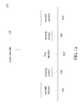
- Fig.1a is the schematic diagram of a preferred embodiment of a multiple sound channels speaker according to this disclosure.
- the multiple sound channels speaker 100 is an integrally multiple sound channels speaker 100, which essentially comprises a first speaker 102, at least one second speaker 104, a plurality of sensing switches 106 and an audio decoder 108.
- the first speaker 102 is adjacent to the second speaker 104, and the first speaker 102 is wired connected to the second speaker 104, or the first speaker 102 is wireless transmitted to the second speaker 104.
- the sensing switch 106 is disposed between the first speaker 102 and the second speaker 104, wherein the sensing switch 106 is a mechanical trigger device or a touched sensing device, and to be emphasized is that this disclosure is not limited to the disclosed embodiments.
- the audio decoder (Audio Codec IC) 108 electrically connected to the sensing switch 106, is used for judging switching condition of the sound channels by means of receiving an output signal form the sensing switch 106.
- the first speaker 102 and the second speaker 104 are connected together to form a single sound channel or dual sound channels speaker.
- the sensing switch 106 disposed between the first speaker 102 and the second speaker 104, outputs a signal to the audio decoder 108. Therefore, the audio decoder 108 switches the multiple sound channels speaker 100 from a single sound channel or dual sound channels speaker to a 2.1 sound channels speaker, and switches the two second speakers 104 to left and right sound channels speakers respectively, and further switches the first speaker 102 to a low-sounding speaker.
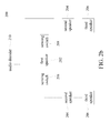
- Fig.2a is the schematic diagram of another embodiment of a multiple sound channels speaker according to this disclosure.
- the multiple sound channels speaker 200 essentially comprises at least one first speaker 202, at least one second speaker 204, at least one third speaker 206, a plurality of sensing switches 208 and an audio decoder 210.
- the first speaker 202 is adjacent to the second speaker 204
- the second speaker 204 is adjacent to the third speaker 206, hence the first speaker 202, the second speaker 204 and the third speaker 206 are wired connected or wireless transmitted to each other.
- the wireless transmitted technologies include but not limited to infrared wireless transmission or blue tooth wireless transmission.
- the sensing switches 208 are disposed between the first speaker 202 and the second speaker 204, and between the second speaker 204 and the third speaker 206 respectively, wherein the sensing switches 208 are mechanical trigger devices or touched sensing devices, and to be emphasized is that this disclosure is not limited to the disclosed embodiments.
- the audio decoder 210 electrically connected to the sensing switches 208, is used for judging switching condition of the sound channels by means of receiving output signals form the sensing switches 208.
- the first speaker 202, the second speaker 204 and the third speaker 206 are connected together.
- the sensing switch 208 disposed between the second speaker 204 and the third speaker 206, outputs a signal to the audio decoder 210. Therefore, the audio decoder 210 switches the multiple sound channels speaker 200 from a single sound channel or dual sound channels speaker to a 2.1 sound channels speaker, and switches two third speakers 206 to left and right sound channels speakers respectively, and further switches the first speaker 202 and second speaker 204 to low- sounding speakers.
- the sensing switch 208 disposed between the first speaker 202 and the second speaker 204, also outputs a signal to the audio decoder 210.
- the multiple sound channels speaker 200 switches from a 2.1 to 5.0 sound channels speaker, wherein the first speaker 202 is the main sound channel speaker, the second speakers 204 are the left-front and right-front sound channels speakers, and the third speakers 206 are the left-rear and right-rear sound channels speakers correspondingly.
- the sensing switches 208 drive the audio decoder 210 to switch sound channels correspondingly, so as to use no any press button.
- the above mentioned embodiments of this disclosure does not limit to merely switch a single sound channel speaker to a 2.1 or 5.0 sound channels speaker, said single sound channel or dual sound channels speakers can be further switched to 2.0, 5.0 or 7.1 sound channels speakers by adding or removing the speakers correspondingly.
- the switching sequence of those speakers is to separate the first speaker 202 from the second speaker 204 first, then separate the second speaker 204 from the third speaker 206, such that the purpose of switching a dual sound channels speaker to a multiple sound channels speaker could be achieved on the same way.
- one of the objectives of this disclosure can be achieved to switch sound channels directly and instinct when said speakers are separated from each other by means of the sensing switches, which is convenient and efficient because it is not necessary for the user to switch the sound channels by utilizing a manual switch.
Landscapes
- Physics & Mathematics (AREA)
- Engineering & Computer Science (AREA)
- Acoustics & Sound (AREA)
- Signal Processing (AREA)
- Stereophonic System (AREA)
Abstract
Description
- This present invention relates to a multiple sound channels speaker, and more particularly to a multiple sound channels speaker which switches different sound channels without any manual switch.
- Nowadays, due to progress of computer technology and internet, much audio and video broadcasting is realized on the computer via the internet. Therefore, many peripheral multimedia apparatuses are highly needed, and more and more high-level speakers are sold, which are 2.0, 5.1 or 7.1 sound channels speakers. Nevertheless, the performances of such 5.1 or 7.1 sound channels speakers are not always needed in any time. That is, in case of phoning internet call, it merely needs single sound channel or dual sound channels speakers, but in case of watching TV/movie or playing electronic games, the single sound channel or dual sound channels speakers should be switched to 5.1 or 7.1 sound channels speakers correspondingly. Even though many speakers capable of switching different sound channels are sold, but a press button is still needed specially to control the different sound channels switching.
- However, the different sound channels are unable to be switched rapidly by utilizing the press button. Therefore, this disclosure discloses a multiple sound channels speaker which switches different sound channels rapidly and instinct to overcome the prior art defect.
- In view of the foregoing prior art defect, the objective of this disclosure is to provide a multiple sound channels speaker capable of switching different sound channels without any press button. Further, another objective of this disclosure is to provide a multiple sound channels speaker capable of switching different sound channels rapidly and instinct
- Accordingly, the multiple sound channels speaker provided comprises a first speaker, a second speaker, a sensing switch and an audio decoder, wherein the second speaker is adjacent to the first speaker, the sensing switch is disposed between the first speaker and the second speaker, and the audio decoder is electrically connected to the sensing switch. When the first speaker is separated from the second speaker, the sensing switch will output a signal to the audio decoder so as to switch sound channels correspondingly.
- Furthermore, the multiple sound channels speaker provided further comprises a first speaker, a second speaker, a third speaker, at least two sensing switches and an audio decoder, wherein the second speaker is adjacent to the first speaker, the third speaker is adjacent to the second speaker, the sensing switches are disposed between the first speaker and the second speaker, and between the second speaker and the third speaker respectively, and the audio decoder is electrically connected to the sensing switch. When the first speaker is separated from the second speaker, or when the second speaker is separated from the third speaker, the sensing switch outputs a signal to the audio decoder, so as to switch sound channels correspondingly.
- A detailed description is given in the following embodiments with reference to the accompanying drawings.
- This disclosure can be more fully understood by referring to the following detailed description and examples with references made to the accompanying drawings, wherein:
-
Fig.1a and1b is the schematic diagram of a preferred embodiment of a multiple sound channels speaker according to this disclosure. -
Fig.2a and2b is the schematic diagram of another embodiment of a multiple sound channels speaker according to this disclosure. - The following description is of the best-contemplated mode of carrying out this disclosure. This description is made for the purpose of illustrating the general principles of this disclosure and should not be taken in a limiting sense. The scope of this disclosure is best determined by reference to the appended claims.
-
Fig.1a is the schematic diagram of a preferred embodiment of a multiple sound channels speaker according to this disclosure. As shown inFig.1a , the multiplesound channels speaker 100 is an integrally multiplesound channels speaker 100, which essentially comprises afirst speaker 102, at least onesecond speaker 104, a plurality ofsensing switches 106 and anaudio decoder 108. Thefirst speaker 102 is adjacent to thesecond speaker 104, and thefirst speaker 102 is wired connected to thesecond speaker 104, or thefirst speaker 102 is wireless transmitted to thesecond speaker 104. Thesensing switch 106 is disposed between thefirst speaker 102 and thesecond speaker 104, wherein thesensing switch 106 is a mechanical trigger device or a touched sensing device, and to be emphasized is that this disclosure is not limited to the disclosed embodiments. The audio decoder (Audio Codec IC) 108, electrically connected to thesensing switch 106, is used for judging switching condition of the sound channels by means of receiving an output signal form thesensing switch 106. Generally, thefirst speaker 102 and thesecond speaker 104 are connected together to form a single sound channel or dual sound channels speaker. As shown inFig.1b , when thefirst speaker 102 is separated from thesecond speaker 104, thesensing switch 106, disposed between thefirst speaker 102 and thesecond speaker 104, outputs a signal to theaudio decoder 108. Therefore, theaudio decoder 108 switches the multiplesound channels speaker 100 from a single sound channel or dual sound channels speaker to a 2.1 sound channels speaker, and switches the twosecond speakers 104 to left and right sound channels speakers respectively, and further switches thefirst speaker 102 to a low-sounding speaker. -
Fig.2a is the schematic diagram of another embodiment of a multiple sound channels speaker according to this disclosure. As shown inFig.2A , the multiplesound channels speaker 200 essentially comprises at least onefirst speaker 202, at least onesecond speaker 204, at least onethird speaker 206, a plurality ofsensing switches 208 and anaudio decoder 210. Thefirst speaker 202 is adjacent to thesecond speaker 204, and thesecond speaker 204 is adjacent to thethird speaker 206, hence thefirst speaker 202, thesecond speaker 204 and thethird speaker 206 are wired connected or wireless transmitted to each other. For instance, the wireless transmitted technologies include but not limited to infrared wireless transmission or blue tooth wireless transmission. Thesensing switches 208 are disposed between thefirst speaker 202 and thesecond speaker 204, and between thesecond speaker 204 and thethird speaker 206 respectively, wherein thesensing switches 208 are mechanical trigger devices or touched sensing devices, and to be emphasized is that this disclosure is not limited to the disclosed embodiments. Theaudio decoder 210, electrically connected to thesensing switches 208, is used for judging switching condition of the sound channels by means of receiving output signals form thesensing switches 208. Generally, thefirst speaker 202, thesecond speaker 204 and thethird speaker 206 are connected together. Besides, when thesecond speaker 204 is separated from thethird speaker 206, thesensing switch 208, disposed between thesecond speaker 204 and thethird speaker 206, outputs a signal to theaudio decoder 210. Therefore, theaudio decoder 210 switches the multiplesound channels speaker 200 from a single sound channel or dual sound channels speaker to a 2.1 sound channels speaker, and switches twothird speakers 206 to left and right sound channels speakers respectively, and further switches thefirst speaker 202 andsecond speaker 204 to low- sounding speakers. - In addition, as shown in
Fig.2B , when thesecond speaker 204 is separated from thefirst speaker 202, thesensing switch 208, disposed between thefirst speaker 202 and thesecond speaker 204, also outputs a signal to theaudio decoder 210. Thus, the multiplesound channels speaker 200 switches from a 2.1 to 5.0 sound channels speaker, wherein thefirst speaker 202 is the main sound channel speaker, thesecond speakers 204 are the left-front and right-front sound channels speakers, and thethird speakers 206 are the left-rear and right-rear sound channels speakers correspondingly. Accordingly, when the above mentioned speakers are separated from each other, thesensing switches 208, disposed among those speakers, drive theaudio decoder 210 to switch sound channels correspondingly, so as to use no any press button. In detail, the above mentioned embodiments of this disclosure does not limit to merely switch a single sound channel speaker to a 2.1 or 5.0 sound channels speaker, said single sound channel or dual sound channels speakers can be further switched to 2.0, 5.0 or 7.1 sound channels speakers by adding or removing the speakers correspondingly. On the other hand, the switching sequence of those speakers is to separate thefirst speaker 202 from thesecond speaker 204 first, then separate thesecond speaker 204 from thethird speaker 206, such that the purpose of switching a dual sound channels speaker to a multiple sound channels speaker could be achieved on the same way. - In sum, one of the objectives of this disclosure can be achieved to switch sound channels directly and instinct when said speakers are separated from each other by means of the sensing switches, which is convenient and efficient because it is not necessary for the user to switch the sound channels by utilizing a manual switch.
- While the invention has been described by way of example and in terms of the preferred embodiments, it is to be understood that the invention is not limited to the disclosed embodiments. To the contrary, it is intended to cover various modifications and similar arrangements. Therefore, the scope of the appended claims should be accorded the broadest interpretation so as to encompass all such modifications and similar arrangements.
Claims (10)
- A multiple sound channels speaker (100) characterized by comprising:a first speaker (102);at least one second speaker (104) adjacent to the first speaker (102);a sensing switch (106) disposed between the first speaker (102) and the second speaker (104); andan audio decoder (108) electrically connected to the sensing switch (106);wherein when the first speaker (102) is separated from the second speaker (104), the sensing switch (106) outputs a signal to the audio decoder (108), so as to switch sound channels correspondingly.
- The multiple sound channels speaker as claimed in claim 1, further comprising at least one third speaker (206), wherein the third speaker (206) is adjacent to the second speaker (104).
- The multiple sound channels speaker as claimed in claim 1, wherein the first speaker (102) is wired connected to the second speaker (104).
- The multiple sound channels speaker as claimed in claim 1, wherein the first speaker (102) is wireless transmitted to the second speaker (104).
- The multiple sound channels speaker as claimed in claim 1, wherein the sensing switch (106) is a mechanical trigger device.
- The multiple sound channels speaker as claimed in claim 1, wherein the sensing switch (106) is a touched sensing device.
- A multiple sound channels speaker characterized by comprising:at least one first speaker (202);at least one second speaker (204) adjacent to the first speaker (202);at least one third speaker (206) adjacent to the second speaker (204);at least two sensing switches (208) disposed between the first speaker (202) and the second speaker (204), and between the second speaker (204) and the third speaker (206) respectively; andan audio decoder (210) electrically connected to the sensing switch (208);wherein when the first speaker (202) is separated from the second speaker (204), or when the second speaker (204) is separated from the third speaker (206), the sensing switch (208) outputs a signal to the audio decoder (210), so as to switch sound channels correspondingly.
- The multiple sound channels speaker as claimed in claim 7, wherein the first speaker (202), the second speaker (204) and the third speaker (206) are wired connected or wireless transmitted to each other.
- The multiple sound channels speaker as claimed in claim 7, wherein the sensing switch (208) is a mechanical trigger device.
- The multiple sound channels speaker as claimed in claim 7, wherein the sensing switch (208) is a touched sensing device.
Priority Applications (1)
| Application Number | Priority Date | Filing Date | Title |
|---|---|---|---|
| EP13167811.2A EP2804397B1 (en) | 2013-05-15 | 2013-05-15 | Speaker system with automatic sound channel switching |
Applications Claiming Priority (1)
| Application Number | Priority Date | Filing Date | Title |
|---|---|---|---|
| EP13167811.2A EP2804397B1 (en) | 2013-05-15 | 2013-05-15 | Speaker system with automatic sound channel switching |
Publications (2)
| Publication Number | Publication Date |
|---|---|
| EP2804397A1 true EP2804397A1 (en) | 2014-11-19 |
| EP2804397B1 EP2804397B1 (en) | 2015-07-08 |
Family
ID=48366249
Family Applications (1)
| Application Number | Title | Priority Date | Filing Date |
|---|---|---|---|
| EP13167811.2A Not-in-force EP2804397B1 (en) | 2013-05-15 | 2013-05-15 | Speaker system with automatic sound channel switching |
Country Status (1)
| Country | Link |
|---|---|
| EP (1) | EP2804397B1 (en) |
Citations (4)
| Publication number | Priority date | Publication date | Assignee | Title |
|---|---|---|---|---|
| US4151470A (en) * | 1974-07-18 | 1979-04-24 | Olympus Optical Co., Ltd. | Combined portable tape recorder and stereophonic receiver system |
| JP2006033077A (en) * | 2004-07-12 | 2006-02-02 | Pioneer Electronic Corp | Speaker unit |
| EP1784049A1 (en) * | 2005-11-08 | 2007-05-09 | BenQ Corporation | A method and system for sound reproduction, and a program product |
| FR2970574A1 (en) * | 2011-01-19 | 2012-07-20 | Devialet | AUDIO PROCESSING DEVICE |
-
2013
- 2013-05-15 EP EP13167811.2A patent/EP2804397B1/en not_active Not-in-force
Patent Citations (4)
| Publication number | Priority date | Publication date | Assignee | Title |
|---|---|---|---|---|
| US4151470A (en) * | 1974-07-18 | 1979-04-24 | Olympus Optical Co., Ltd. | Combined portable tape recorder and stereophonic receiver system |
| JP2006033077A (en) * | 2004-07-12 | 2006-02-02 | Pioneer Electronic Corp | Speaker unit |
| EP1784049A1 (en) * | 2005-11-08 | 2007-05-09 | BenQ Corporation | A method and system for sound reproduction, and a program product |
| FR2970574A1 (en) * | 2011-01-19 | 2012-07-20 | Devialet | AUDIO PROCESSING DEVICE |
Also Published As
| Publication number | Publication date |
|---|---|
| EP2804397B1 (en) | 2015-07-08 |
Similar Documents
| Publication | Publication Date | Title |
|---|---|---|
| US8528012B2 (en) | Interactive remote control system and method | |
| US20090089675A1 (en) | Method for providing graphical user interface and video apparatus using the same | |
| ES2645148T3 (en) | Audio processor for orientation dependent processing | |
| WO2007040053A1 (en) | Video sound output device and external loudspeaker controller | |
| WO2011155192A1 (en) | Video generation device, method and integrated circuit | |
| EP3319340B1 (en) | Speaker apparatus, electronic apparatus connected therewith, and controlling method thereof | |
| US9118998B2 (en) | Multiple sound channels speaker | |
| US9516405B2 (en) | Multimedia playing system and sound channel control method thereof | |
| CN102868472A (en) | Wireless terminal adapted to control broadcast in external device | |
| US20120207333A1 (en) | Sound Box | |
| CN101039398A (en) | Method for playing television audio and television for realizing the same | |
| CN101039395A (en) | Multi-picture television capable of switching audio and switching method | |
| EP2207261A1 (en) | Audio device, AV system having the audio device, and method to control the audio device | |
| KR101611843B1 (en) | Sound signal return type earphone for smart device | |
| KR102585907B1 (en) | A multi-functional remote control | |
| KR20110056391A (en) | Systems and Methods for Television Integrated Surround Sound Systems | |
| EP2804397B1 (en) | Speaker system with automatic sound channel switching | |
| CN103813240B (en) | multi-channel speakers | |
| CN113360126B (en) | Electronic device and control method | |
| KR20160029626A (en) | Settop box, method and computer program for providing service using the same | |
| CN101304243A (en) | Method and device for controlling individual volume of channel switching of electronic product | |
| GB201211589D0 (en) | An audio effects control device | |
| CN106210762A (en) | Method, source device, purpose equipment, TV and the terminal that audio frequency is play | |
| CN105654977B (en) | Shadow and KTV combination type processing equipments | |
| JP5526216B2 (en) | Multichannel speakers |
Legal Events
| Date | Code | Title | Description |
|---|---|---|---|
| PUAI | Public reference made under article 153(3) epc to a published international application that has entered the european phase |
Free format text: ORIGINAL CODE: 0009012 |
|
| 17P | Request for examination filed |
Effective date: 20140321 |
|
| AK | Designated contracting states |
Kind code of ref document: A1 Designated state(s): AL AT BE BG CH CY CZ DE DK EE ES FI FR GB GR HR HU IE IS IT LI LT LU LV MC MK MT NL NO PL PT RO RS SE SI SK SM TR |
|
| AX | Request for extension of the european patent |
Extension state: BA ME |
|
| GRAP | Despatch of communication of intention to grant a patent |
Free format text: ORIGINAL CODE: EPIDOSNIGR1 |
|
| INTG | Intention to grant announced |
Effective date: 20150126 |
|
| GRAS | Grant fee paid |
Free format text: ORIGINAL CODE: EPIDOSNIGR3 |
|
| GRAA | (expected) grant |
Free format text: ORIGINAL CODE: 0009210 |
|
| AK | Designated contracting states |
Kind code of ref document: B1 Designated state(s): AL AT BE BG CH CY CZ DE DK EE ES FI FR GB GR HR HU IE IS IT LI LT LU LV MC MK MT NL NO PL PT RO RS SE SI SK SM TR |
|
| REG | Reference to a national code |
Ref country code: GB Ref legal event code: FG4D |
|
| REG | Reference to a national code |
Ref country code: AT Ref legal event code: REF Ref document number: 736180 Country of ref document: AT Kind code of ref document: T Effective date: 20150715 Ref country code: CH Ref legal event code: EP |
|
| REG | Reference to a national code |
Ref country code: IE Ref legal event code: FG4D |
|
| REG | Reference to a national code |
Ref country code: DE Ref legal event code: R096 Ref document number: 602013002181 Country of ref document: DE |
|
| REG | Reference to a national code |
Ref country code: AT Ref legal event code: MK05 Ref document number: 736180 Country of ref document: AT Kind code of ref document: T Effective date: 20150708 |
|
| REG | Reference to a national code |
Ref country code: NL Ref legal event code: MP Effective date: 20150708 |
|
| REG | Reference to a national code |
Ref country code: LT Ref legal event code: MG4D |
|
| PG25 | Lapsed in a contracting state [announced via postgrant information from national office to epo] |
Ref country code: LT Free format text: LAPSE BECAUSE OF FAILURE TO SUBMIT A TRANSLATION OF THE DESCRIPTION OR TO PAY THE FEE WITHIN THE PRESCRIBED TIME-LIMIT Effective date: 20150708 Ref country code: LV Free format text: LAPSE BECAUSE OF FAILURE TO SUBMIT A TRANSLATION OF THE DESCRIPTION OR TO PAY THE FEE WITHIN THE PRESCRIBED TIME-LIMIT Effective date: 20150708 Ref country code: NO Free format text: LAPSE BECAUSE OF FAILURE TO SUBMIT A TRANSLATION OF THE DESCRIPTION OR TO PAY THE FEE WITHIN THE PRESCRIBED TIME-LIMIT Effective date: 20151008 Ref country code: FI Free format text: LAPSE BECAUSE OF FAILURE TO SUBMIT A TRANSLATION OF THE DESCRIPTION OR TO PAY THE FEE WITHIN THE PRESCRIBED TIME-LIMIT Effective date: 20150708 Ref country code: GR Free format text: LAPSE BECAUSE OF FAILURE TO SUBMIT A TRANSLATION OF THE DESCRIPTION OR TO PAY THE FEE WITHIN THE PRESCRIBED TIME-LIMIT Effective date: 20151009 |
|
| PG25 | Lapsed in a contracting state [announced via postgrant information from national office to epo] |
Ref country code: AT Free format text: LAPSE BECAUSE OF FAILURE TO SUBMIT A TRANSLATION OF THE DESCRIPTION OR TO PAY THE FEE WITHIN THE PRESCRIBED TIME-LIMIT Effective date: 20150708 Ref country code: IS Free format text: LAPSE BECAUSE OF FAILURE TO SUBMIT A TRANSLATION OF THE DESCRIPTION OR TO PAY THE FEE WITHIN THE PRESCRIBED TIME-LIMIT Effective date: 20151108 Ref country code: RS Free format text: LAPSE BECAUSE OF FAILURE TO SUBMIT A TRANSLATION OF THE DESCRIPTION OR TO PAY THE FEE WITHIN THE PRESCRIBED TIME-LIMIT Effective date: 20150708 Ref country code: SE Free format text: LAPSE BECAUSE OF FAILURE TO SUBMIT A TRANSLATION OF THE DESCRIPTION OR TO PAY THE FEE WITHIN THE PRESCRIBED TIME-LIMIT Effective date: 20150708 Ref country code: ES Free format text: LAPSE BECAUSE OF FAILURE TO SUBMIT A TRANSLATION OF THE DESCRIPTION OR TO PAY THE FEE WITHIN THE PRESCRIBED TIME-LIMIT Effective date: 20150708 Ref country code: HR Free format text: LAPSE BECAUSE OF FAILURE TO SUBMIT A TRANSLATION OF THE DESCRIPTION OR TO PAY THE FEE WITHIN THE PRESCRIBED TIME-LIMIT Effective date: 20150708 Ref country code: PT Free format text: LAPSE BECAUSE OF FAILURE TO SUBMIT A TRANSLATION OF THE DESCRIPTION OR TO PAY THE FEE WITHIN THE PRESCRIBED TIME-LIMIT Effective date: 20151109 Ref country code: PL Free format text: LAPSE BECAUSE OF FAILURE TO SUBMIT A TRANSLATION OF THE DESCRIPTION OR TO PAY THE FEE WITHIN THE PRESCRIBED TIME-LIMIT Effective date: 20150708 |
|
| REG | Reference to a national code |
Ref country code: DE Ref legal event code: R097 Ref document number: 602013002181 Country of ref document: DE |
|
| REG | Reference to a national code |
Ref country code: FR Ref legal event code: PLFP Year of fee payment: 4 |
|
| PG25 | Lapsed in a contracting state [announced via postgrant information from national office to epo] |
Ref country code: IT Free format text: LAPSE BECAUSE OF FAILURE TO SUBMIT A TRANSLATION OF THE DESCRIPTION OR TO PAY THE FEE WITHIN THE PRESCRIBED TIME-LIMIT Effective date: 20150708 Ref country code: SK Free format text: LAPSE BECAUSE OF FAILURE TO SUBMIT A TRANSLATION OF THE DESCRIPTION OR TO PAY THE FEE WITHIN THE PRESCRIBED TIME-LIMIT Effective date: 20150708 Ref country code: CZ Free format text: LAPSE BECAUSE OF FAILURE TO SUBMIT A TRANSLATION OF THE DESCRIPTION OR TO PAY THE FEE WITHIN THE PRESCRIBED TIME-LIMIT Effective date: 20150708 Ref country code: EE Free format text: LAPSE BECAUSE OF FAILURE TO SUBMIT A TRANSLATION OF THE DESCRIPTION OR TO PAY THE FEE WITHIN THE PRESCRIBED TIME-LIMIT Effective date: 20150708 Ref country code: DK Free format text: LAPSE BECAUSE OF FAILURE TO SUBMIT A TRANSLATION OF THE DESCRIPTION OR TO PAY THE FEE WITHIN THE PRESCRIBED TIME-LIMIT Effective date: 20150708 |
|
| PLBE | No opposition filed within time limit |
Free format text: ORIGINAL CODE: 0009261 |
|
| STAA | Information on the status of an ep patent application or granted ep patent |
Free format text: STATUS: NO OPPOSITION FILED WITHIN TIME LIMIT |
|
| PG25 | Lapsed in a contracting state [announced via postgrant information from national office to epo] |
Ref country code: RO Free format text: LAPSE BECAUSE OF FAILURE TO SUBMIT A TRANSLATION OF THE DESCRIPTION OR TO PAY THE FEE WITHIN THE PRESCRIBED TIME-LIMIT Effective date: 20150708 |
|
| 26N | No opposition filed |
Effective date: 20160411 |
|
| PG25 | Lapsed in a contracting state [announced via postgrant information from national office to epo] |
Ref country code: SI Free format text: LAPSE BECAUSE OF FAILURE TO SUBMIT A TRANSLATION OF THE DESCRIPTION OR TO PAY THE FEE WITHIN THE PRESCRIBED TIME-LIMIT Effective date: 20150708 Ref country code: BE Free format text: LAPSE BECAUSE OF NON-PAYMENT OF DUE FEES Effective date: 20160531 |
|
| PG25 | Lapsed in a contracting state [announced via postgrant information from national office to epo] |
Ref country code: LU Free format text: LAPSE BECAUSE OF FAILURE TO SUBMIT A TRANSLATION OF THE DESCRIPTION OR TO PAY THE FEE WITHIN THE PRESCRIBED TIME-LIMIT Effective date: 20160515 Ref country code: BE Free format text: LAPSE BECAUSE OF FAILURE TO SUBMIT A TRANSLATION OF THE DESCRIPTION OR TO PAY THE FEE WITHIN THE PRESCRIBED TIME-LIMIT Effective date: 20150708 |
|
| REG | Reference to a national code |
Ref country code: CH Ref legal event code: PL |
|
| PG25 | Lapsed in a contracting state [announced via postgrant information from national office to epo] |
Ref country code: CH Free format text: LAPSE BECAUSE OF NON-PAYMENT OF DUE FEES Effective date: 20160531 Ref country code: LI Free format text: LAPSE BECAUSE OF NON-PAYMENT OF DUE FEES Effective date: 20160531 |
|
| REG | Reference to a national code |
Ref country code: IE Ref legal event code: MM4A |
|
| REG | Reference to a national code |
Ref country code: FR Ref legal event code: PLFP Year of fee payment: 5 |
|
| PG25 | Lapsed in a contracting state [announced via postgrant information from national office to epo] |
Ref country code: IE Free format text: LAPSE BECAUSE OF NON-PAYMENT OF DUE FEES Effective date: 20160515 |
|
| PG25 | Lapsed in a contracting state [announced via postgrant information from national office to epo] |
Ref country code: NL Free format text: LAPSE BECAUSE OF FAILURE TO SUBMIT A TRANSLATION OF THE DESCRIPTION OR TO PAY THE FEE WITHIN THE PRESCRIBED TIME-LIMIT Effective date: 20150708 |
|
| REG | Reference to a national code |
Ref country code: FR Ref legal event code: PLFP Year of fee payment: 6 |
|
| PG25 | Lapsed in a contracting state [announced via postgrant information from national office to epo] |
Ref country code: HU Free format text: LAPSE BECAUSE OF FAILURE TO SUBMIT A TRANSLATION OF THE DESCRIPTION OR TO PAY THE FEE WITHIN THE PRESCRIBED TIME-LIMIT; INVALID AB INITIO Effective date: 20130515 Ref country code: SM Free format text: LAPSE BECAUSE OF FAILURE TO SUBMIT A TRANSLATION OF THE DESCRIPTION OR TO PAY THE FEE WITHIN THE PRESCRIBED TIME-LIMIT Effective date: 20150708 |
|
| PG25 | Lapsed in a contracting state [announced via postgrant information from national office to epo] |
Ref country code: MC Free format text: LAPSE BECAUSE OF FAILURE TO SUBMIT A TRANSLATION OF THE DESCRIPTION OR TO PAY THE FEE WITHIN THE PRESCRIBED TIME-LIMIT Effective date: 20150708 Ref country code: MK Free format text: LAPSE BECAUSE OF FAILURE TO SUBMIT A TRANSLATION OF THE DESCRIPTION OR TO PAY THE FEE WITHIN THE PRESCRIBED TIME-LIMIT Effective date: 20150708 Ref country code: CY Free format text: LAPSE BECAUSE OF FAILURE TO SUBMIT A TRANSLATION OF THE DESCRIPTION OR TO PAY THE FEE WITHIN THE PRESCRIBED TIME-LIMIT Effective date: 20150708 Ref country code: MT Free format text: LAPSE BECAUSE OF NON-PAYMENT OF DUE FEES Effective date: 20160531 |
|
| PG25 | Lapsed in a contracting state [announced via postgrant information from national office to epo] |
Ref country code: BG Free format text: LAPSE BECAUSE OF FAILURE TO SUBMIT A TRANSLATION OF THE DESCRIPTION OR TO PAY THE FEE WITHIN THE PRESCRIBED TIME-LIMIT Effective date: 20150708 |
|
| PG25 | Lapsed in a contracting state [announced via postgrant information from national office to epo] |
Ref country code: AL Free format text: LAPSE BECAUSE OF FAILURE TO SUBMIT A TRANSLATION OF THE DESCRIPTION OR TO PAY THE FEE WITHIN THE PRESCRIBED TIME-LIMIT Effective date: 20150708 Ref country code: TR Free format text: LAPSE BECAUSE OF FAILURE TO SUBMIT A TRANSLATION OF THE DESCRIPTION OR TO PAY THE FEE WITHIN THE PRESCRIBED TIME-LIMIT Effective date: 20150708 |
|
| PGFP | Annual fee paid to national office [announced via postgrant information from national office to epo] |
Ref country code: FR Payment date: 20210412 Year of fee payment: 9 Ref country code: DE Payment date: 20210420 Year of fee payment: 9 |
|
| PGFP | Annual fee paid to national office [announced via postgrant information from national office to epo] |
Ref country code: GB Payment date: 20210421 Year of fee payment: 9 |
|
| REG | Reference to a national code |
Ref country code: DE Ref legal event code: R119 Ref document number: 602013002181 Country of ref document: DE |
|
| GBPC | Gb: european patent ceased through non-payment of renewal fee |
Effective date: 20220515 |
|
| PG25 | Lapsed in a contracting state [announced via postgrant information from national office to epo] |
Ref country code: FR Free format text: LAPSE BECAUSE OF NON-PAYMENT OF DUE FEES Effective date: 20220531 |
|
| PG25 | Lapsed in a contracting state [announced via postgrant information from national office to epo] |
Ref country code: GB Free format text: LAPSE BECAUSE OF NON-PAYMENT OF DUE FEES Effective date: 20220515 Ref country code: DE Free format text: LAPSE BECAUSE OF NON-PAYMENT OF DUE FEES Effective date: 20221201 |