EP2804187B1 - Preparation method for a bonded la(fe, si)13 base magnetocaloric effect material - Google Patents
Preparation method for a bonded la(fe, si)13 base magnetocaloric effect material Download PDFInfo
- Publication number
- EP2804187B1 EP2804187B1 EP12850893.4A EP12850893A EP2804187B1 EP 2804187 B1 EP2804187 B1 EP 2804187B1 EP 12850893 A EP12850893 A EP 12850893A EP 2804187 B1 EP2804187 B1 EP 2804187B1
- Authority
- EP
- European Patent Office
- Prior art keywords
- alloy
- magnetocaloric
- solidification
- alloy particles
- temperature
- Prior art date
- Legal status (The legal status is an assumption and is not a legal conclusion. Google has not performed a legal analysis and makes no representation as to the accuracy of the status listed.)
- Not-in-force
Links
Images











Classifications
-
- H—ELECTRICITY
- H01—ELECTRIC ELEMENTS
- H01F—MAGNETS; INDUCTANCES; TRANSFORMERS; SELECTION OF MATERIALS FOR THEIR MAGNETIC PROPERTIES
- H01F1/00—Magnets or magnetic bodies characterised by the magnetic materials therefor; Selection of materials for their magnetic properties
- H01F1/01—Magnets or magnetic bodies characterised by the magnetic materials therefor; Selection of materials for their magnetic properties of inorganic materials
- H01F1/012—Magnets or magnetic bodies characterised by the magnetic materials therefor; Selection of materials for their magnetic properties of inorganic materials adapted for magnetic entropy change by magnetocaloric effect, e.g. used as magnetic refrigerating material
- H01F1/015—Metals or alloys
-
- F—MECHANICAL ENGINEERING; LIGHTING; HEATING; WEAPONS; BLASTING
- F25—REFRIGERATION OR COOLING; COMBINED HEATING AND REFRIGERATION SYSTEMS; HEAT PUMP SYSTEMS; MANUFACTURE OR STORAGE OF ICE; LIQUEFACTION SOLIDIFICATION OF GASES
- F25B—REFRIGERATION MACHINES, PLANTS OR SYSTEMS; COMBINED HEATING AND REFRIGERATION SYSTEMS; HEAT PUMP SYSTEMS
- F25B21/00—Machines, plants or systems, using electric or magnetic effects
-
- F—MECHANICAL ENGINEERING; LIGHTING; HEATING; WEAPONS; BLASTING
- F25—REFRIGERATION OR COOLING; COMBINED HEATING AND REFRIGERATION SYSTEMS; HEAT PUMP SYSTEMS; MANUFACTURE OR STORAGE OF ICE; LIQUEFACTION SOLIDIFICATION OF GASES
- F25B—REFRIGERATION MACHINES, PLANTS OR SYSTEMS; COMBINED HEATING AND REFRIGERATION SYSTEMS; HEAT PUMP SYSTEMS
- F25B2321/00—Details of machines, plants or systems, using electric or magnetic effects
- F25B2321/002—Details of machines, plants or systems, using electric or magnetic effects by using magneto-caloric effects
Definitions
- the present invention belongs to magnetocaloric material field.
- the present invention relates to the preparation of a high-strength, bonded La(Fe,Si) 13 -based magnetocaloric material.
- the present invention relates to the preparation of a high-strength La(Fe,Si) 13 -based magnetocaloric material obtained by a bonding and thermoset method using an adhesive agent such as epoxide-resin glue, polyimide adhesive and so on.
- Magnetic refrigeration technology as characterized by environment friendly, energy efficient, stable and reliable, has drawn great attention worldwide in recent years.
- Several types of giant magnetocaloric materials at room temperature and even high temperature zone were found successionally in US, China, Holland and Japan, which significantly increased the expectation for environment friendly magnetic refrigeration technology, e.g. Gd-Si-Ge, LaCaMnO 3 Ni-Mn-Ga, La (Fe, Si) 13 -based compound, Mn-Fe-P-As, MnAs-based compound, etc.
- Common features of these novel giant magnetocaloric materials lie in that their magnetic entropy changes are all higher than that of the traditional magnetic refrigeration material Gd working around room temperature (R.
- La(Fe,Si) 13 -based compound is commonly accepted worldwide and has the highest potential for magnetic refrigeration application in a high temperature zone or even at R.T.
- This alloy has many characters shown as follows: the cost of its raw material is low; phase-transition temperature, phase-transition property and hysteresis loss may vary upon component adjustment; its magnetic entropy change around R.T. is higher than that of Gd by one fold.
- La(Fe,Si) 13 -based magnetic refrigeration material has been used for prototype test, which proved its refrigerating capacity is better than that of Gd.
- phase-transition property of La(Fe,Si) 13 -based compounds varies with the adjustment of its components.
- its phase-transition property is normally of the first-order in nature.
- the first-order nature of phase-transition property is weakened and gradually transitted to the second order; hysteresis loss decreased gradually (no hysteresis loss for the second-order phase transition).
- the range of magnetocaloric effect was reduced in turn.
- phase-transition temperature peak temperature of magnetocaloric
- La(Fe,Si) 13 -based compounds shows low compressive strength, fragile and poor corrosion resisting ability due to its strong magnetocrystalline coupling property (the intrinsic property of the material).
- Samples made from certain components have been cracked into pieces right after being made, and even pulverized naturally if being kept in air.
- Dut to its fragility the material, while used as a magnetic refrigeration material in a refrigeration cycle, is cracked into powder, which blocks the circulating path and thus reduces magnetic refrigeration efficiency and shorten refrigerator's lifetime.
- Chinese patent application CN101755312A discloses a reactive sintered magnetic heat-exchanging material and a method for preparing the same.
- Said material comprises a (La 1-a M a )(Fe 1-b-c T b Y c ) 13-d -based alloy prepared by steps of mixing precurs or powders such as a La precursor, a Fe precursor and a Y precursor etc.; compressing the mixture into a green body; sintering the green body at a temperature of 1000 ⁇ 1200°C for a period of 2 ⁇ 24 hours to form a phase having a composition of (La 1-a M a )(Fe 1-b-c T b Y c ) 13-d .
- a La(Fe,Si) 13 -based magnetocaloric material can be manufactured into a working material shape satisfying the requirement of a magnetic refrigerator.
- a La(Fe,Si) 13 -based room-temperature magnetocaloric material doped with Co as normally having second-order phase-transition property (weak magnetocrystalline coupling, and magnetic phase transition accompanied with slower and weaker lattice expansion)
- the resultant material processes certain compressive strength and shows no (or less) microcrack druing the cyclic process.
- La(Fe,Si) 13 -based material strong magnetocrystalline coupling, and magnetic phase transition accompanied with significant lattice expansion
- the working material with a regular shape manufactured by the ceramimetallurgical method unavoidably shows microcracks or breaks druing the cyclic process, which means an undesired mechanical property thereby restricts the application of the material.
- US 2010/047527 A1 , US 2011/020661 A1 , US 2011/030939 A1 , and US 2006/231163 A1 disclose La(Fe,Si) 13 -based magnetocaloric powders with particle sizes below 200 ⁇ m, bound in a polymeric material.
- the invention provides a method for preparing a magnetocaloric material according to claim 1.
- the invention provides a high-strength La(Fe,Si) 13 -based magnetocaloric material prepared by a bonding-thermosetting method using an adhesive agent (e.g. epoxide-resin glue, polyimide adhesive, etc.), a method for preparing the same and use thereof.
- an adhesive agent e.g. epoxide-resin glue, polyimide adhesive, etc.
- a high-strength, bonded La (Fe, Si) 13 -based magnetocaloric material can be obtained.
- Magnetic entropy change (a parameter characterizing magnetocaloric effect) range remains substantially the same, as compared with that before the bonding; the magnetic hysteresis loss declines as the forming pressure increases; and the effective refrigerating capacity, after the maximum loss being deducted, remains unchanged or enhanced.
- the refrigerating working materials may be manufactured into any shapes and sizes based on the actual need required by a magnetic refrigerator.
- Epoxide-resin glue is an adhesive agent compring epoxy resin as its main part and containing a corresponding curing agent and accelerating agent. Solidification period, solidification temperature, and mechanical parameters such as strength and tenacity, etc. of solidified material rely on the type and proportion of epoxy resin as well as the corresponding curing agent and accelerating agent.
- thermosetting forming method due to the low price (about 40-50 RMB/kg) of the organic adhesive agents such as epoxide-resin glue, polyimide adhesive and the like, preparation of a high-strength La(Fe,Si) 13 -based magnetocaloric material by a thermosetting forming method is very important to the magnetic refrigerating application of this type of materials in practice.
- the "NaZn 13 -type structure" or “1: 13 structure” corresponding to the terms “LaFe 13-x M x " as used herein means a structure in which the space group is Fm 3 c .
- Fe atom occupies two crystal sites 8b (Fe I ) and 96i (Fe II ) in a ratio of 1: 12, respectively.
- La and Fe I atoms constitute CsCl structure, in which La atom is surrounded by 24 Fe II atoms; Fe I atom is surrounded by 12 Fe II atoms constituting an icosahedron; and around each Fe II atom, there are 9 nearest-neighbor Fe II atoms, 1 Fe I atom and 1 La atom.
- the invention provides a preparation method for a high-strength, bonded La(Fe,Si) 13 -based magnetocaloric material, which comprises magnetocaloric alloy particles and an adhesive agent, wherein the magnetocaloric alloy particles have a particle size in the range of ⁇ 800 ⁇ m, and are bonded into a massive material by the adhesive agent; wherein, the magnetocaloric alloy particles have a NaZn 13 -type structure and is represented by a chemical formula: La 1-x R x (Fe 1-p-q Co p Mn q ) 13-y Si y A ⁇ , wherein,
- the composition of the magnetocaloric alloy used in the preparation method is not specifically restricted, provided that it is a La(Fe,Si) 13 -based magnetocaloric alloy having a main phase in a NaZn 13 -type structure. Because the La(Fe,Si) 13 -based magnetocaloric alloys having especially the properties of a first-order phase-transition shows low compressive strength, fragile and poor corrosion resisting ability, etc., the technical solutions involving a bonding step utilizing an adhesive agent according to the invention are very useful for the alloy described above.
- the adhesive agent in the preparation method for the magnetocaloric material according to the invention, relative to 100 parts by weight of the magnetocaloric alloy particles; the adhesive agent is in an amount of 1 ⁇ 10 parts by weight, preferably 2 ⁇ 5 parts by weight.
- the adhesive agent can be selected from various adhesive agents commonly used in prior art, provided that it enables the magnetocaloric alloy particles of the invention to be bonded into a massive material.
- the adhesive agent can be selected from one or more of epoxide-resin glue, polyimide adhesive, or epoxy resin (EP), urea resin, phenol-formaldehyde resin, diallyl phthalate (DAP) and the like.
- the adhesive agent used in the invention is selected from one or both of epoxide-resin glue and polyimide adhesive.
- the preparation method for the magnetocaloric material according to the invention can, while the magnetic field changes from 0 to 5 T, show an effective magnetic entropy change value of 1.0 ⁇ 50.0 J/kgK, more preferably 5.0 ⁇ 50.0 J/kgK and a range of phase-transition temperature of 10 ⁇ 450 K.
- the magnetocaloric alloy particles have a particle size in the range of 15-200 ⁇ m.
- the bonded La (Fe, Si) 13 -based magnetocaloric material of the invention also shows significantly reduced hysteresis loss, besides its high strength.
- hysteresis loss was reduced gradually upon the decrease of the particle size.
- the particle size was decreased into the range of 15 ⁇ 50 ⁇ m, the hysteresis loss was remarkably reduced by 64%.
- A represents interstitial atoms (e.g. carbon, hydrogen and boron) with small atomic radii. All these interstitial atoms, while added, occupy the 24d-interstitial position in the NaZn 13 structure and have the same impact on structure.
- the magnetocaloric alloy particles are represented by a chemical formula: La 1-x R x (Fe 1-p Co p ) 13-y Si y A ⁇ , wherein,
- the invention provides a method of preparing the magnetocaloric material described above, which comprises the steps of:
- the dry and wet mixing methods are carried out as below:
- wet mixing method the adhesive agent as well as its curing agent and accelerating agent are dissolved proportionally in a mixture solution of acetone and absolute ethanol (generally, the curing agent is dissolvable in acetone and the accelerating agent is dissolvable in ethanol), to formulate a glue solution.
- Dissolving method the adhesive agent, curing agent and accelerating agent powder are weighted in proportion and poured into the acetone and absolute ethanol mixture solution (the amount of the acetone and absolute ethanol solution should be minimized, optimally just allowing the complete dissolution of the solute), and agitated to achieve complete dissolution of the powder. Then the resultant glue solution is mixed with the magnetocaloric alloy particles in proportion, agitated evenly and dried at 25 ⁇ 100 °C.
- step 5 the press forming is carried out under a compressing pressure of 0.1-1.3 GPa for a compressing period of 1-10 mins.
- the mixture of the adhesive agent and alloy particles is press formed into shapes and sizes satisfying the requirement of magnetic refrigerators.
- the mixture of the adhesive agent and alloy particles is placed in a mould (in a shape and size determined in accordance with the actual needs of magnetic refrigerators for materials), press formed at room temperature, and then released from the mould.
- solidification in step 5), solidification can be performed in inert gas or in vaccum.
- the solidification condition includes a solidification temperature of 100-200°C, a solidification period of 1-60 mins, and an inert gas pressure of 10 -2 Pa -10 MPa or vacuum degree of ⁇ 1 Pa.
- the amount of hydrogen can be controlled by adjusting hydrogen pressure, solidification temperature and solidification period.
- the hydrogen pressure can be 10 -2 Pa -10 MPa; the solidification temperature can be 100-200°C, and the solidification period can be 10-60 mins.
- the amount of hydrogen absorbed by the alloy of the invention relies on the temperature and pressure during hydrogen absorption process. By regulating the temperature and pressure during hydrogen absorption, the amount of the absorbed hydrogen can be adjusted.
- the hydrogen absorption process can be performed under progressively increased pressures, and different amount of hydrogen can be absorbed if the hydrogen absorption process is terminated at different pressure.
- the raw materials La and R can be commercially available elementary rare earth elements, or industrial-pure LaCe alloy and/or industrial-pure LaCePrNd mischmetal.
- Commercialized industrial-pure LaCe alloy normally has a purity of 95-98 at.% (atomic ratio) and an atomic ratio of La:Ce in the range of 1: 1.6-1: 2.3;and the industrial-pure LaCePrNd mischmetal normally has a purity of about 99 wt.%.
- the insufficience of La element in the material to be prepared, as compared with LaCe alloy, can be supplemented by elementary La.
- industrial-pure LaCePrNd mischmetal can also be processed in accordance with above.
- a in the chemical formula includes carbon and/or boron element(s), preferably the carbon and/or boron can be provided by FeC and/or FeB alloy(s), respectively. Since FeC and FeB alloys also contain Fe element, the amount of the added elementary Fe needs to be properly reduced, so that the ratio of the added elements still meets the requirement for the atomic ratio in the chemical formula of the magnetic material.
- the step 2) comprises steps of placing the raw material prepared in step 1) into an arc furnace; vacuuming the arc furnace to reach a vacuum degree less than 1 ⁇ 10 -2 Pa; purging the furnace chamber with argon gas having a purity higher than 99 wt.% once or twice; then filling the furnace chamber with the argon gas to reach 0.5-1.5 atm; and arcing; so as to obtain the alloy ingots; wherein each alloy ingot is smelted at 1500-2500°C for 1-6 times repeatedly.
- the step 3) comprises steps of annealing the alloy ingots obtained in step 2) at 1000-1400°C, with a vacuum degree less than 1 ⁇ 10 -3 Pa, for 1 hour - 60 days; then quenching the alloy ingots in liquid nitrogen or water, or furnace cooling the alloy ingots to room temperature.
- a magnetic refrigerator can comprise a magnetocaloric material prepared by a method provided in the invention.
- Example 1 Preparation of high-strength magnetocaloric material LaFe 11.6 Si 1.4 C 0.2
- Example 2 Preparation of high-strength magnetocaloric material La 0.7 Ce 0.3 Fe 11.6 Si 1.4 C 0.2
- Example 2 the epoxide-resin glue used in this Example was same as that in Example 1; the solidification temperature was lower than that in Example 1, which decreased the magnetocaloric effect reduction caused by the potential oxidation of the material during solidification. However, it was found that under the same forming pressure and in the same solifidation atmosphere, solidification at a low solidification temperature made the compressive strength to decline somewhat, but the compressive strength was still considerable, i.e. 136.7 MPa. Similar to the case in Example 1, the magnetic entropy change range and refrigerating capacity of the material were maintained unchanged essentially before and after the solidification.
- Example 3 Preparation of high-strength magnetocaloric material La 0.7 (Ce,Pr,Nd) 0.3 (Fe 0.9 Co 0.1 ) 11.9 Si 1.1
- phase-transition temperature was around room temperature and the phase-transition was of second-order in nature, indicating that a high-strength, second-order, room-temperature magnetocaloric material can be obtained directly using a bonding method, which is very important to the magnetic refrigerating application in practice.
- Example 4 Preparation of high-strength magnetocaloric material La 0.5 Pr 0.5 Fe 11.0 Si 2.0 H 2.6
- La(Fe, Si) 13 -based hydride with considerable compressive strength can be obtained by solidifying the bonded La (Fe, Si) 13 -based magnetocaloric material in hydrogen atmosphere; the temperature at which the maximal magnetic entropy change occurs can be adjusted to around 350K, which is very important to the magnetic refrigerating application in practice.
- Example 5 Preparation of high-strength magnetocaloric material LaFe 11.6 Si 1.4 C 0.2
- the high temperatures (250°C, 300 °C and 400°C) used in this Example were higher than the solidification temperatures (160°C, 170°C and 130°C) in Examples 1-3; and the forming pressure (2.0 ⁇ 2.5 GPa) of this Example was also higher than those in the three proceding Examples, i.e. ⁇ 1 GPa, ⁇ 1.3 GPa and 1 GPa.
- Example 6 La 0.7 Ce 0.3 Fe 11.6 Si 1.4 C 0.2 magnetocaloric material showing small hysteresis loss
- Figures 27 (a) and (b) show the M-H curves and magnetic entropy change-temperature curves for the particles with size range reduced to ⁇ 10 ⁇ m, respectively. From Figure 27 , it can be observed that while the particle size was reduced to ⁇ 10 ⁇ m, although maximal magnetic hysteresis was further reduced to 27 J/kg, separation of ⁇ -Fe phase allowed the magnitude of magnetocaloric effect to be decreased to 21 J/kgK. In Figure 27(a) , the M-H curve is still in a curl shape in the high temperature 1:13-phase paramagnetic zone, which is caused by ⁇ -Fe impurity phase and indicates the separation of ⁇ -Fe phase.
- Example 7 Preparation of two high-strength magnetocaloric materials La 0.7 (Ce,Pr,Nd) 0.3 Fe 11.6 Si 1.4 C 0.1 H 2.9 and La 0.7 Pr 0.3 F 11.5 Si 1.5 C 0.2 B 0.05 H 0.55
- La (Fe, Si) 13 -based carbon/boron/hydrogen interstitial compounds with considerable compressive strength can be obtained by solidifying the bonded La(Fe,Si) 13 -based carbon/boron compounds in hydrogen atmosphere; the temperature at which the maximal magnetic entropy change occurs can be adjusted towards to high-temperature zone significantly through the hydrogen absorption process, which is very important to the magnetic refrigerating application in practice.
- Example 3 Considering this Example in combination with Example 3, it can be confirmed that a La(Fe, Si) 13 -based magnetocaloric material having a main phase in a NaZn 13 -type structure and a larger component range (Co content: 0 ⁇ p ⁇ 0.2, Mn content: 0 ⁇ q ⁇ 0.2, Si content: 0.8 ⁇ y ⁇ 2) can be prepared from industrial-pure LaCe alloy and industrial-pure La-Ce-Pr-Nd as raw materials, using said preparation method. A bonded La(Fe,Si) 13 -based magnetocaloric material with high compressive strength can be obtained by the said bonding process.
Landscapes
- Engineering & Computer Science (AREA)
- Power Engineering (AREA)
- Physics & Mathematics (AREA)
- Mechanical Engineering (AREA)
- Thermal Sciences (AREA)
- General Engineering & Computer Science (AREA)
- Hard Magnetic Materials (AREA)
- Powder Metallurgy (AREA)
- Manufacture Of Metal Powder And Suspensions Thereof (AREA)
Description
- The present invention belongs to magnetocaloric material field. Particularly, the present invention relates to the preparation of a high-strength, bonded La(Fe,Si)13-based magnetocaloric material. More particularly, the present invention relates to the preparation of a high-strength La(Fe,Si)13-based magnetocaloric material obtained by a bonding and thermoset method using an adhesive agent such as epoxide-resin glue, polyimide adhesive and so on.
- Over 15% of the total energy consumption is used for refrigeration. Now, the commonly used gas compression refrigeration technology has Carnot cycle efficiency up to only about 25%, and the gas refrigerant used in gas compression refrigeration damages atmospheric ozone layer and induces greenhouse effect. Therefore, exploration of pollution-free and environment friendly refrigeration materials and development of novel refrigeration technologies with low energy consumption and high efficiency become very urgent in the whole world.
- Magnetic refrigeration technology, as characterized by environment friendly, energy efficient, stable and reliable, has drawn great attention worldwide in recent years. Several types of giant magnetocaloric materials at room temperature and even high temperature zone were found successionally in US, China, Holland and Japan, which significantly increased the expectation for environment friendly magnetic refrigeration technology, e.g. Gd-Si-Ge, LaCaMnO3 Ni-Mn-Ga, La (Fe, Si)13-based compound, Mn-Fe-P-As, MnAs-based compound, etc. Common features of these novel giant magnetocaloric materials lie in that their magnetic entropy changes are all higher than that of the traditional magnetic refrigeration material Gd working around room temperature (R. T.), their phase-transition properties are of the first-order, most of them show strong magnetocrystalline coupling characteristics, and magnetic phase transition is accompanied with distinct crystalline stuctural transition. These novel materials also show different features. For example, Gd-Si-Ge is not only expensive but also requires further purification of the raw material while being prepared. And the raw materials used to prepare Mn-Fe-P-As and MnAs-based compound, etc. are toxic; NiMn-based Heusler alloy shows large hysteresis loss, and so on.
- Among the several novel materials found in the past over ten years, La(Fe,Si)13-based compound is commonly accepted worldwide and has the highest potential for magnetic refrigeration application in a high temperature zone or even at R.T. This alloy has many characters shown as follows: the cost of its raw material is low; phase-transition temperature, phase-transition property and hysteresis loss may vary upon component adjustment; its magnetic entropy change around R.T. is higher than that of Gd by one fold. In the laboratories of many countries, La(Fe,Si)13-based magnetic refrigeration material has been used for prototype test, which proved its refrigerating capacity is better than that of Gd.
- The investigation also showed that the phase-transition property of La(Fe,Si)13-based compounds varies with the adjustment of its components. For example, for the compounds with low Si amout, its phase-transition property is normally of the first-order in nature. Upon the increasing of Co content and rising of Curie temperature, the first-order nature of phase-transition property is weakened and gradually transitted to the second order; hysteresis loss decreased gradually (no hysteresis loss for the second-order phase transition). However, due to the change of components and exchange interaction, the range of magnetocaloric effect was reduced in turn. Addition of Mn lowered the Curie temperature by impacting the exchange interaction; the first-order phase-transition property weakened; hysteresis loss decreased gradually; and the range of magnetocaloric effect was reduced in turn. In contrast, it was found that replacement of La with small rare earth magnetic atoms (e.g. Ce, Pr, Nd) can enhance the first-order phase-transition property; and increase hysteresis loss and the range of magnetocaloric effect. It was also found that introduction of interstitial atom (e.g. C, H, B, etc.) with small atomic radii can increase Curie temperature; and enable magnetocaloric effect to occur in a higher temperature zoon. For instance, where the content of the interstitial atom H in molecular formula LaFe11.5Si1.5Hα increased from α = 0 to α = 1.8, the phase-transition temperature (peak temperature of magnetocaloric) was raised from 200K to 350K. It was expected that the first-order phase-transition La(Fe,Si)13-based compound showing a giant magnetocaloric effect can be used in actural magnetic refrigeration application, so as to achieve ideal refrigerating effect.
- However, La(Fe,Si)13-based compounds (particularly, first-order phase-transition material) shows low compressive strength, fragile and poor corrosion resisting ability due to its strong magnetocrystalline coupling property (the intrinsic property of the material). Samples made from certain components have been cracked into pieces right after being made, and even pulverized naturally if being kept in air. Dut to its fragility, the material, while used as a magnetic refrigeration material in a refrigeration cycle, is cracked into powder, which blocks the circulating path and thus reduces magnetic refrigeration efficiency and shorten refrigerator's lifetime.
- Chinese patent application
CN101755312A discloses a reactive sintered magnetic heat-exchanging material and a method for preparing the same. Said material comprises a (La1-aMa)(Fe1-b-cTbYc)13-d-based alloy prepared by steps of mixing precurs or powders such as a La precursor, a Fe precursor and a Y precursor etc.; compressing the mixture into a green body; sintering the green body at a temperature of 1000∼1200°C for a period of 2∼24 hours to form a phase having a composition of (La1-aMa)(Fe1-b-cTbYc)13-d. Using such a ceramimetallurgical method, a La(Fe,Si)13-based magnetocaloric material can be manufactured into a working material shape satisfying the requirement of a magnetic refrigerator. For example, a La(Fe,Si)13-based room-temperature magnetocaloric material doped with Co, as normally having second-order phase-transition property (weak magnetocrystalline coupling, and magnetic phase transition accompanied with slower and weaker lattice expansion), can be manufactured by the ceramimetallurgical method into a working material shape satisfying the requirement of a sample machine. The resultant material processes certain compressive strength and shows no (or less) microcrack druing the cyclic process. However, regarding a first-order phase-transition La(Fe,Si)13-based material (strong magnetocrystalline coupling, and magnetic phase transition accompanied with significant lattice expansion), the working material with a regular shape manufactured by the ceramimetallurgical method unavoidably shows microcracks or breaks druing the cyclic process, which means an undesired mechanical property thereby restricts the application of the material.US 2010/047527 A1 ,US 2011/020661 A1 ,US 2011/030939 A1 , andUS 2006/231163 A1 disclose La(Fe,Si)13-based magnetocaloric powders with particle sizes below 200µm, bound in a polymeric material. - The invention provides a method for preparing a magnetocaloric material according to
claim 1. - Compared with prior art, the present invention has advantages shown as follows:
- (1)By introducing a small amount of adhesive agent into the La(Fe,Si)13-based magnetocaloric material; using a thermosetting forming method; and adjusting the forming pressure, thermosetting temperature, thermosetting atmosphere and so on, a high-strength, bonded La(Fe,Si)13-based magnetocaloric material can be obtained, thereby overcoming the intrinsic property, i.e. fragility of the material.
- (2)Magnetic entropy change (a parameter characterizing magnetocaloric effect) range remains substantially the same, as compared with that before the bonding; the magnetic hysteresis loss declines as the forming pressure increases; and the effective refrigerating capacity, after the maximum loss being deducted, remains unchanged or enhanced.
- (3)Refrigerating working materials may be manufactured into any shapes and sizes based on the actual need required by a magnetic refrigerator.
- (4)The method of preparing the high-strength, bonded La(Fe,Si)13-based magnetocaloric material according to the invention is simple, and can be operated and industrialized easily. Additionly, due to the low price (about 40∼50 RMB/kg) of the adhesive agent used in the invention, the high-strength La(Fe,Si)13-based magnetocaloric material prepared by the thermosetting forming method still has a cost efficient advantadge, which is very important to the magnetic refrigerating application of this type of materials in practice.
- The invention is further illustrated with reference to the following figures, wherein:
-
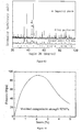
Figure 1 shows the X-ray Diffraction (XRD) spectra, at room temperature, of the LaFe11.6Si1.4C0.2 alloy particles and the massive material obtained by mixing the alloy particles with an adhensive agent, forming the mixture under different forming pressure and solidifying the formed material in argon atmosphere and in vaccum according to Example 1. The insert shows the pattern of the LaFe11.6Si1.4C0.2 alloy particles obtained in step (4) of Example 1 in the invention; -
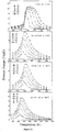
Figure 2 shows the thermomagnetic (M-T) curves, in a magnetic field of 0.02T, of the LaFe11.6Si1.4C0.2 alloy particles and the massive material obtained by mixing the alloy particles with an adhensive agent, forming the mixture under different forming pressure and solidifying the formed material in argon atmosphere and in vaccum according to Example 1; -
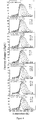
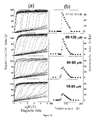
Figure 3 shows the magnetization curves (M-H curve), at different temperatures, in the process of increasing and decreasing the field, of the LaFe11.6Si1.4C0.2 alloy particles and the massive material obtained by mixing the alloy particles with an adhensive agent, forming the mixture under different forming pressure and solidifying the formed material in argon atmosphere and in vaccum according to Example 1; as well as the dependency of hysteresis loss on temperature; -
Figure 4 indicates the dependency of magnetic entropy change (ΔS) on temperature, in various magnetic fields, for the LaFe11.6Si1.4C0.2 alloy particles and the massive material obtained by mixing the alloy particles with an adhensive agent, forming the mixture under different forming pressure and solidifying the formed material in argon atmosphere and in vaccum according to Example 1 (calculation of ΔS in the process of increasing the field); -
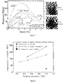
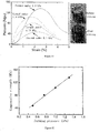
Figure 5 shows the relation between the bearing pressure and strain of the massive material obtained in step (7) of Example 1, and the insert shows the pattern of the massive material and that after the crush under a pressure; -
Figure 6 shows the dependency of the compressive strength of the massive material obtained in step (7) of Example 1 on the forming pressure; -
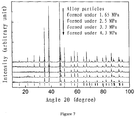
Figure 7 shows the X-ray Diffraction (XRD) spectra, at room temperature, of the La0.7Ce0.3Fe11.6Si1.4C0.2 alloy particles and the massive material obtained by mixing the alloy particles with an adhensive agent, forming the mixture under different forming pressure and solidifying the formed material in vaccum according to Example 2; -
Figure 8 shows the thermomagnetic (M-T) curves, in a magnetic field of 0.02T, of the La0.7Ce0.3Fe11.6Si1.4C0.2 alloy particles and the massive material obtained by mixing the alloy particles with an adhensive agent, forming the mixture under different forming pressure and solidifying the formed material in vaccum according to Example 2; -
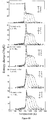
Figure 9 shows the magnetization curves (M-H curve), at different temperatures, in the process of increasing and decreasing the field, of the La0.7Ce0.3Fe11.6Si1.4C0.2 alloy particles and the massive material obtained by mixing the alloy particles with an adhensive agent, forming the mixture under different forming pressure and solidifying the formed material in vaccum according to Example 2; as well as the dependency of hysteresis loss on temperature; -
Figure 10 indicates the dependency of magnetic entropy change (ΔS) on temperature, in various magnetic fields, for the La0.7Ce0.3Fe11.6Si1.4C0.2 alloy particles and the massive material obtained by mixing the alloy particles with an adhensive agent, forming the mixture under different forming pressure and solidifying the formed material in vaccum according to Example 2 (calculation of ΔS in the process of increasing the field); -
Figure 11 shows the relation between the bearing pressure and strain of the massive material obtained by forming the La0.7Ce0.3Fe11.6Si1.4C0.2 alloy particles under different forming pressure and solidifying the formed material in vaccum according to Example 2, and the insert shows the patterns of the massive material and that after the crushed under a pressure; -
Figure 12 shows the dependency of the compressive strength of the massive material obtained in step (7) of Example 2 on the forming pressure; -
Figure 13 shows the X-ray Diffraction (XRD) spectra, at room temperature, of the La0.7 (Ce, Pr, Nd)0.3(Fe0.9Co0.1)11.9Si1.1 alloy particles and the massive material formed under 1.0 GPa and solidified in vaccum according to Example 3; -
Figure 14 shows the relation between the bearing pressure and strain of the sample obtained by forming La0.7(Ce,Pr,Nd)0.3(Fe0.9Co0.1)11.9Si1.1 alloy particles under 1.0 GPa and solidifying the formed material according to Example 3; -
Figure 15 shows the X-ray Diffraction (XRD) spectrum, at room temperature, of the bonded La0.5Pr0.5Fe11.0Si2.0H2.6 massive material prepared in Example 4; -
Figure 16 shows the thermomagnetic (M-T) curves, in a magnetic field of 0.02T, of the bonded La0.5Pr0.5Fe11.0Si2.0H2.6 massive material prepared in Example 4; -
Figure 17 indicates the dependency of ΔS of the bonded La0.5Pr0.5Fe11.0Si2.0H2.6 massive material prepared in Example 4 on temperature in the process of increasing the field, in various magnetic fields; -
Figure 18 shows the relation between the bearing pressure and strain of the bonded La0.5Pr0.5Fei11.0Si2.0H2.6 massive material prepared in Example 4; -
Figure 19 shows the thermomagnetic (M-T) curves, in a magnetic field of 0.02T, of the LaFe11.6Si1.4C0.2 alloy particles and the massive material obtained by mixing the alloy particles with an adhensive agent, forming and solidifying the mixture under various solidification temperature according to Example 5; -
Figure 20 shows the thermomagnetic (M-T) curves of the LaFe11.6Si1.4C0.2 alloy particles and the massive material obtained by mixing the alloy particles with an adhensive agent, forming and solidifying the mixture under various solidification temperature according to Example 5, in the process of increasing and decreasing the field, at different temperatures; -
Figure 21 indicates the dependency of magnetic entropy change (ΔS) on temperature, in various magnetic fields for the LaFe11.6Si1.4C0.2 alloy particles and the massive material obtained by mixing the alloy particles with an adhensive agent, forming and solidifying the mixture under various solidification temperatures according to Example 5 (calculation of ΔS in the process of increasing the field); -
Figure 22 shows the relation between the bearing pressure and strain of the massive material obtained by forming and solidifying LaFe11.6Si1.4C0.2 alloy particles under various solidification temperatures according to Example 5; -
Figure 23 shows the X-ray Diffraction (XRD) spectrum, at room temperature, of the La0.7Ce0.3Fe11.6Si1.4C0.2 bulk prepared in Example 6; -
Figure 24 shows the thermomagnetic (M-T) curves, in a magnetic field of 0.02T, of the La0.7Ce0.3Fe11.6Si1.4C0.2 bulk and samples with a particle size within 3 ranges prepared in Example 6; -
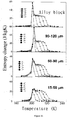
Figure 25 shows a) the magnetization curves (M-H curve), at different temperatures, in the process of increasing and decreasing the field, of the La0.7Ce0.3Fe11.6Si1.4C0.2 bulk and samples with a particle size within 3 ranges prepared in Example 6; b) the dependency of hysteresis loss on temperature; -
Figure 26 indicates the dependency of ΔS of the La0.7Ce0.3Fe11.6Si1.4C0.2 bulk and samples with a particle size within 3 ranges prepared in Example 6 on temperature in the process of increasing the field, in various magnetic fields; -
Figure 27 shows a) the thermomagnetic (M-T) curves; b) the dependency of ΔS on temperature in the process of increasing the field, in various magnetic fields for the sample with a particle size in the range of <10 µm prepared in Example 6; -
Figure 28 shows the X-ray Diffraction (XRD) spectrum, at room temperature, of the La0.7(Ce,Pr,Nd)0.3Fe11.6Si1.4C0.1H2.9 bulk prepared in Example 7; -
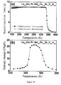
Figure 29 shows a) the thermomagnetic (M-T) curves, in a magnetic field of 0.02T; b) the dependency of magnetic entropy change (ΔS) on temperature while magnetic field changes from 0T to 5T (calculation of ΔS in the process of increasing the field) for the La0.7(Ce,Pr,Nd)0.3Fe11.6Si1.4C0.1H2.9 hydride prepared in Example 7, after being bonded and solidified; -
Figure 30 shows a) the thermomagnetic (M-T) curves, in a magnetic field of 0.02T; b) the dependency of magnetic entropy change (ΔS) on temperature while magnetic field changes from 0T to 5T (calculation of ΔS in the process of increasing the field) for the La0.7Pr0.3Fe11.5Si1.5C0.2B0.05H0.55 hydride prepared in Example 7, after being bonded and solidified; -
Figure 31 shows the X-ray Diffraction (XRD) spectra, at room temperature, of the massive materials obtained by forming the three alloys U0.8Ce0.2Fe11.4Si1.6Bα (α=0, 0.2 and 0.4) prepred in Example 8 under 1.0 GPa and solidifying the formed materials in vaccum; -
Figure 32 shows the thermomagnetic (M-T) curves, in a magnetic field of 0.02T, of the massive materials obtained by forming the three alloys La0.8Ce0.2Fe11.4Si1.6Bα (α=0, 0.2 and 0.4) prepred in Example 8 under 1.0 GPa and solidifying the formed materials in vaccum; -
Figure 33 indicates the dependency of magnetic entropy change (ΔS) on temperature while magnetic field changes from 0T to 5T for the massive materials obtained by forming the three alloys La0.8Ce0.2Fe11.4Si1.6Bα (α=0, 0.2 and 0.4) prepred in Example 8 under 1.0 GPa and solidifying the formed materials in vaccum (calculation of ΔS in the process of increasing the field); -
Figure 34 shows the X-ray Diffraction (XRD) spectra, at room temperature, of the two alloy blocks La0.9Ce0.1 (Fe0.6Co0.2Mn0.2)13-ySiy (y=0.9 and 1.8) prepred in Example 9; -
Figure 35 shows the thermomagnetic (M-T) curves, in a magnetic field of 0.02T, of the two alloy blocks La0.9Ce0.1 (Fe0.6Co0.2Mn0.2)13-ySiy (y=0.9 and 1.8) prepred in Example 9; and -
Figure 36 shows the thermomagnetic (M-T) curves, in a magnetic field of 0.02T, of the two alloy blocks La0.9(Ce,Pr,Nd)0.1(Fe0.6Co0.2Mn0.2)13-ySiy (y=0.9 and 1.8) prepred in Example 9. - The present invention is further described in details by referring to the objectives of the invention.
- Particularly, the invention provides a high-strength La(Fe,Si)13-based magnetocaloric material prepared by a bonding-thermosetting method using an adhesive agent (e.g. epoxide-resin glue, polyimide adhesive, etc.), a method for preparing the same and use thereof. It has been found by the inventors that by introducing an adhesive agent, using a thermosetting forming method, selecting a proper adhesive agent, adjusting forming pressure, thermosetting temperature and thermosetting atmosphere, etc., a high-strength, bonded La (Fe, Si)13-based magnetocaloric material can be obtained. Magnetic entropy change (a parameter characterizing magnetocaloric effect) range remains substantially the same, as compared with that before the bonding; the magnetic hysteresis loss declines as the forming pressure increases; and the effective refrigerating capacity, after the maximum loss being deducted, remains unchanged or enhanced. In addition, the refrigerating working materials may be manufactured into any shapes and sizes based on the actual need required by a magnetic refrigerator. Epoxide-resin glue is an adhesive agent compring epoxy resin as its main part and containing a corresponding curing agent and accelerating agent. Solidification period, solidification temperature, and mechanical parameters such as strength and tenacity, etc. of solidified material rely on the type and proportion of epoxy resin as well as the corresponding curing agent and accelerating agent. Moreover, due to the low price (about 40-50 RMB/kg) of the organic adhesive agents such as epoxide-resin glue, polyimide adhesive and the like, preparation of a high-strength La(Fe,Si)13-based magnetocaloric material by a thermosetting forming method is very important to the magnetic refrigerating application of this type of materials in practice.
- For better understanding of the invention, some terms are defined as follows. The terms defined herein have the meaning generally understood by those skilled in the art.
- Unless otherwise indicated, the "NaZn13-type structure" or "1: 13 structure" corresponding to the terms "LaFe13-xMx" as used herein means a structure in which the space group is Fm3c . Fe atom occupies two crystal sites 8b (FeI) and 96i (FeII) in a ratio of 1: 12, respectively. La and FeI atoms constitute CsCl structure, in which La atom is surrounded by 24 FeII atoms; FeI atom is surrounded by 12 FeII atoms constituting an icosahedron; and around each FeII atom, there are 9 nearest-neighbor FeII atoms, 1 FeI atom and 1 La atom. For LaFe13-xMx (M = Al, Si) compound, its neutron diffraction experiment showed that the 8b site is fully occupied by Fe atom; and 96i site is occupied by M atom and the rest Fe atom randomly.
- The invention provides a preparation method for a high-strength, bonded La(Fe,Si)13-based magnetocaloric material, which comprises magnetocaloric alloy particles and an adhesive agent, wherein the magnetocaloric alloy particles have a particle size in the range of ≤ 800 µm, and are bonded into a massive material by the adhesive agent; wherein, the magnetocaloric alloy particles have a NaZn13-type structure and is represented by a chemical formula:
La1-xRx (Fe1-p-qCopMnq)13-ySiyAα,
wherein, - R is one or more selected from elements cerium (Ce), praseodymium (Pr) and neodymium (Nd),
- A is one or more selected from elements carbon (C), hydrogen (H) and boron (B),
- x is in the range of 0≤ x≤ 0.5,
- y is in the range of 0.8≤ y≤ 2,
- p is in the range of 0≤ p≤ 0.2,
- q is in the range of 0≤ q≤ 0.2,
- α is in the range of 0≤ α≤ 3.0.
- In the present invention, the composition of the magnetocaloric alloy used in the preparation method is not specifically restricted, provided that it is a La(Fe,Si)13-based magnetocaloric alloy having a main phase in a NaZn13-type structure. Because the La(Fe,Si)13-based magnetocaloric alloys having especially the properties of a first-order phase-transition shows low compressive strength, fragile and poor corrosion resisting ability, etc., the technical solutions involving a bonding step utilizing an adhesive agent according to the invention are very useful for the alloy described above.
- Preferably, in the preparation method for the magnetocaloric material according to the invention, relative to 100 parts by weight of the magnetocaloric alloy particles; the adhesive agent is in an amount of 1∼10 parts by weight, preferably 2∼5 parts by weight. The adhesive agent can be selected from various adhesive agents commonly used in prior art, provided that it enables the magnetocaloric alloy particles of the invention to be bonded into a massive material. For instance, the adhesive agent can be selected from one or more of epoxide-resin glue, polyimide adhesive, or epoxy resin (EP), urea resin, phenol-formaldehyde resin, diallyl phthalate (DAP) and the like. Preferably, the adhesive agent used in the invention is selected from one or both of epoxide-resin glue and polyimide adhesive.
- Preferably, the preparation method for the magnetocaloric material according to the invention can, while the magnetic field changes from 0 to 5 T, show an effective magnetic entropy change value of 1.0∼50.0 J/kgK, more preferably 5.0∼50.0 J/kgK and a range of phase-transition temperature of 10∼450 K.
- In the magnetocaloric material provided in the invention, the magnetocaloric alloy particles have a particle size in the range of 15-200 µm.
- It has been found by the inventors that when the particle size of the magnetocaloric alloy particles according to the invention is not greater than 200 µm, the bonded La (Fe, Si)13-based magnetocaloric material of the invention also shows significantly reduced hysteresis loss, besides its high strength. As demonstrated in Example 6 of the invention, hysteresis loss was reduced gradually upon the decrease of the particle size. When the particle size was decreased into the range of 15∼50 µm, the hysteresis loss was remarkably reduced by 64%.
- In the chemical formula representing the magnetocaloric alloy particles of the invention, A represents interstitial atoms (e.g. carbon, hydrogen and boron) with small atomic radii. All these interstitial atoms, while added, occupy the 24d-interstitial position in the NaZn13 structure and have the same impact on structure. As the number of the interstitial atoms is increased, the phase-transition temperature (the peak temperature of magnetocaloric effect) moves towards the higher temperature zone. For example, where the amount of interstitial atom H in molecular formula LaFe11.5Si1.5Hα was increased from α = 0 to α =1.8, the phase-transition temperature is raised from 200K to 350K.
- In a preferred embodiment of the invention, the magnetocaloric alloy particles are represented by a chemical formula:
La1-xRx (Fe1-pCop)13-ySiyAα,
wherein, - R is selected from one or more of elements Ce, Pr and Nd,
- A is selected from one, two or three of elements H, C and B,
- x is in the range of 0≤ x≤ 0.5,
- y is in the range of 1≤ y≤ 2,
- p is in the range of 0≤ p≤ 0.1,
- α is in the range of 0≤ α≤ 2.6.
- The invention provides a method of preparing the magnetocaloric material described above, which comprises the steps of:
- 1) formulating raw materials according to the chemical formula, or formulating raw materials other than hydrogen according to the chemical formula where A in the chemical formula includes hydrogen element;
- 2) placing the raw material formulated in step 1) in an arc furnace, vacuuming and purging it with an inert gas, and smelting it under the protection of an inert gas so as to obtain alloy ingots, wherein the inert gas is preferably argon gas;
- 3) vacuum annealing the alloy ingots obtained in step 2) and then quenching the alloy ingots in liquid nitrogen or water, or furnace cooling the alloy ingots to room temperature, so as to obtain the magnetocaloric alloy La1-xRx (Fe1-p-qCopMnq)13-ySiyAα having a NaZn13-type structure;
- 4) crushing the magnetocaloric alloy obtained in step 3) so as to obtain magnetocaloric alloy particles with a particle size of 15-200 µm;
- 5) mixing the adhesive agent with the magnetocaloric alloy particles obtained in step 4) evenly, press forming and solidifying the mixture into a massive material, wherein the press forming is carried out under a compressing pressure of 0.1-1.3GPa for a compressing period of 1-10 mins;
- Preferably, in some embodiments of the invention, the dry and wet mixing methods are carried out as below:
- Dry mixing method: the adhesive agent (e.g. epoxide-resin glue, polyimide adhesive, etc.) as well as its corresponding curing agent and accelerating agent (both are pulverous) are mixed with the magnetocaloric alloy particles, as dry powder, in proportion (relative to 100 parts by weight of the magnetocaloric alloy particles, the total amount of the adhesive agent, curing agent and accelerating agent is≤ 10 parts by weight), and agitated evenly; wherein the curing agent is normally in an amount of 2∼15 wt% of the adhesive agent and plays a role in solidification of the adhesive agent; and the accelerating agent is normally in an amout of 1∼8 wt% of the adhesive agent and functions to reduce solidification temperature and shorten solidification period.
- Wet mixing method: the adhesive agent as well as its curing agent and accelerating agent are dissolved proportionally in a mixture solution of acetone and absolute ethanol (generally, the curing agent is dissolvable in acetone and the accelerating agent is dissolvable in ethanol), to formulate a glue solution. The proportion (weight ratio) is as follow: "adhesive agent: curing agent: accelerating agent = 100 : (2∼15) : (1∼8)". Dissolving method: the adhesive agent, curing agent and accelerating agent powder are weighted in proportion and poured into the acetone and absolute ethanol mixture solution (the amount of the acetone and absolute ethanol solution should be minimized, optimally just allowing the complete dissolution of the solute), and agitated to achieve complete dissolution of the powder. Then the resultant glue solution is mixed with the magnetocaloric alloy particles in proportion, agitated evenly and dried at 25∼100 °C.
- According to the invention, in step 5), the press forming is carried out under a compressing pressure of 0.1-1.3 GPa for a compressing period of 1-10 mins.
- Particularly, the mixture of the adhesive agent and alloy particles is press formed into shapes and sizes satisfying the requirement of magnetic refrigerators. The mixture of the adhesive agent and alloy particles is placed in a mould (in a shape and size determined in accordance with the actual needs of magnetic refrigerators for materials), press formed at room temperature, and then released from the mould.
- According to another preferred embodiment of the preparation method of the invention, in step 5), solidification can be performed in inert gas or in vaccum. The solidification condition includes a solidification temperature of 100-200°C, a solidification period of 1-60 mins, and an inert gas pressure of 10-2 Pa -10 MPa or vacuum degree of <1 Pa.
- Where A in the chemical formula includes hydrogen element, in step 5), the amount of hydrogen can be controlled by adjusting hydrogen pressure, solidification temperature and solidification period. Preferably, the hydrogen pressure can be 10-2 Pa -10 MPa; the solidification temperature can be 100-200°C, and the solidification period can be 10-60 mins. It should be pointed out that the amount of hydrogen absorbed by the alloy of the invention relies on the temperature and pressure during hydrogen absorption process. By regulating the temperature and pressure during hydrogen absorption, the amount of the absorbed hydrogen can be adjusted. In addition, the hydrogen absorption process can be performed under progressively increased pressures, and different amount of hydrogen can be absorbed if the hydrogen absorption process is terminated at different pressure.
- In the present invention, the raw materials La and R can be commercially available elementary rare earth elements, or industrial-pure LaCe alloy and/or industrial-pure LaCePrNd mischmetal. Commercialized industrial-pure LaCe alloy normally has a purity of 95-98 at.% (atomic ratio) and an atomic ratio of La:Ce in the range of 1: 1.6-1: 2.3;and the industrial-pure LaCePrNd mischmetal normally has a purity of about 99 wt.%. The insufficience of La element in the material to be prepared, as compared with LaCe alloy, can be supplemented by elementary La. Similarly, industrial-pure LaCePrNd mischmetal can also be processed in accordance with above.
- Where A in the chemical formula includes carbon and/or boron element(s), preferably the carbon and/or boron can be provided by FeC and/or FeB alloy(s), respectively. Since FeC and FeB alloys also contain Fe element, the amount of the added elementary Fe needs to be properly reduced, so that the ratio of the added elements still meets the requirement for the atomic ratio in the chemical formula of the magnetic material.
- All the other raw materials in the chemical formula are commercially available elementary substance.
- According to another preferred embodiment of the preparation method of the invention, specifically, the step 2) comprises steps of placing the raw material prepared in step 1) into an arc furnace; vacuuming the arc furnace to reach a vacuum degree less than 1×10⁻²Pa; purging the furnace chamber with argon gas having a purity higher than 99 wt.% once or twice; then filling the furnace chamber with the argon gas to reach 0.5-1.5 atm; and arcing; so as to obtain the alloy ingots; wherein each alloy ingot is smelted at 1500-2500°C for 1-6 times repeatedly.
- According to yet another preferred embodiment of the preparation method of the invention, specifically, the step 3) comprises steps of annealing the alloy ingots obtained in step 2) at 1000-1400°C, with a vacuum degree less than 1×10⁻³Pa, for 1 hour - 60 days; then quenching the alloy ingots in liquid nitrogen or water, or furnace cooling the alloy ingots to room temperature. A magnetic refrigerator can comprise a magnetocaloric material prepared by a method provided in the invention.
- The invention is further described by referring to the Examples. It needs to be clarified that the following Examples are provided for the purpose of illustrating the invention only and are not intended to restrict the scope of the invention by any means. Any modification made by a person skilled in the art in light of the invention shall belong to the extent sought to be protected by the claims of the application.
- The raw materails and equipments used in the Examples are described as follows:
- (1) Raw materials La, Ce, Pr, Fe, Co, Mn, Si, FeC and the purities thereof are shown as follows. Elementary La with a purity of 99.52 wt.% and elementary Pr with a purity of 98.97 wt.% were purchased from Hunan Shenghua Rare Earth Metal Material Ltd. Industrial-pure raw material LaCePrNd mischmetal was purchased from Inner Mongolia Baotou Steel Rare Earth International Trade Ltd., with two different purities: (a) the industrial-pure LaCePrNd mischmetal having a purity of 99.6 wt.% used in Example 3 (La, Ce, Pr, Nd elements are in a ratio of 28.27 wt.% La: 50.46 wt.% Ce: 5.22 wt. %Pr: 15.66 wt.% Nd), and (b) the industrial-pure LaCePrNd mischmetal having a purity of 98.2 wt.% used in Examples 7 and 9 (La, Ce, Pr, Nd elements are in a ratio of 25.32 wt.% La: 52.85 wt.% Ce : 4.52 wt.% Pr : 15.51 wt.% Nd). Industrial-pure LaCe alloy was purchased from Inner Mongolia Baotou Steel Rare Earth International Trade Ltd., with a purity of 99.17 wt.% and a La: Ce atomic ratio of 1: 1.88. Elementary Fe with a purity of 99.9 wt% was purchased from Beijing Research Institute for Nonferrous Metals; FeC (99.9 wt%, Fe, C weight ratio of 95.76: 4.24) was smelted from elementary C and Fe having a purity of 99.9 wt%; FeB alloy (99.9 wt.%, Fe, B weight ratio of 77.6: 22.4) was purchased from Beijing Zhongke Sanhuan High Technology Ltd.; Si (99.91 wt%) was purchased from Beijing Research Institute for Nonferrous Metals; Co (99.97 wt%) was purchased from Beijing Research Institute for Nonferrous Metals; and Mn (99.8 wt.%) was purchased from Beijing Shuanghuan Chemical Reagent Factory. All the above raw materials were in blocks.
- (2) Raw material "epoxide-resin BT-801 powder (corresponding curing agent and accelerating agent have been mixed in this product)" was purchased from BONT Surface Treatment Material Co., Ltd, Dongguan City, China; "superfine epoxy resin powder", "superfine latent Q curing agent (micronized dicyandiamide)" and "superfine latent SH-A100 accelerating agent" were purchased from Xinxi Metallurgical Chemical Co., Ltd, Guangzhou City, China; and raw materials polyimide adhesive agent powder and silane coupling agent were purchased from AlfaAesar (Tianjing) Chemical Co., Ltd.
- (3) The arc furnace (Model: WK-II non-consumable vacuum arc furnace) was manufactured by Beijing Wuke Electrooptical Technology Ltd.; the Cu-targeted X-ray diffractometer (Model: RINT2400) was manufactured by Rigaku; and the Superconducting Quantum Interference Vibrating Sample Magnetometer (Model: MPMS (SQUID) VSM) was manufactured by Quantum Design (USA). P-C-T (pressure-composition-temperature) tester was purchased from Beijing Zhongke Yuda Teaching Equipment Department. The oil hydraulic press (Model: 769YP-24B) was purchased from Keqi Hi-tech Company of Tianjin. The six-anvil hydraulic press (Model: DS-029B) was purchased from Jinan Foundry & Metalforming Machinery Research Institute, First Industry Department. The electronic universal testing machine (Model: CMT4305) was purchased from Shenzhen Sans Material Testing Co. Ltd.
-
- 1) The materials were prepared in accordance with the chemical formula LaFe11.6Si1.4C0.2. The raw materials included La, Ce, Fe, Si and FeC. FeC alloy was used to provide C (carbon). The amount of the elementary Fe added thereto was reduced properly since the FeC alloy also contains Fe element, so that the proportion of each element added still met the requirement for the atomic ratio in the chemical formula of the magnetic material.
- 2) The raw materials formulated in step 1), after mixed, was loaded into an arc furnace. The arc furnace was vacuumized to a pressure of 2×10⁻³ Pa, purged with high-purity argon with a purity of 99.996wt% twice, and then filled with high-purity argon with a purity of 99.996wt% to a pressure of 1 atm. The arc was struck (the raw matertials were smelted together to form alloy after striking) to generate alloy ingots. Each alloy ingot was smelted at a temperature of 2000°C repeatedly for 4 times. After the smelting, the ingot alloys were obtained by cooling down in a copper crucible.
- 3) After wrapped separately with molybdenum foil and sealed in a vacuumized quartz tube (1×10⁻⁴Pa), the ingot alloy obtained from step 2) was annealed at 1080°C for 30 days followed by being quenched in liquid nitrogen by breaking the quartz tube. As a result, LaFe11.6Si1.4C0.2 alloy having a NaZn13-type structure were obtained.
- 4) The LaFe11.6Si1.4C0.2 alloy obtained in step 3) was divided into irregular particles with an average partice size in the range of 20-200 micron and a pattern of particles shown as the insert of
Figure 1 . - 5) A glue solution was prepared with the "epoxide-resin BT-801 powder (corresponding curing agent and accelerating agent have been mixed in this product)" purchased from BONT Surface Treatment Material Co., Ltd, Dongguan City, China. The weight ratio of acetone: absolute ethanol: BT-801 epoxide-resin glue was 1: 1: 1. Dissolving method: a solution of acetone and absolute ethanol, after mixed, was poured to BT-801 epoxide-resin powder; the mixture was agitated until the powder was dissolved completely in the solution, indicating the accomplishment of preparation of the glue solution. Then the resultant glue solution was poured to the LaFe11.6Si1.4C0.2 particles obtained in step 4) according to a weigt ratio as below: "alloy particles : BT-801 epoxide-resin powder" = "100: 2.5", mixed evenly, and laid flat in an oven at 50°C until died out. The drying period was 180 mins.
- 6) The LaFe11.6Si1.4C0.2 alloy particles (having been mixed with the adhesive agent) obtained in step 5) were press formed into a cylinder (diameter: 5mm; height: 7mm). The procedure is shown as below: the alloy particles were, after mixed with the adhesive agent, loaded into a mould (in a shape of cylinder with a diameter of 5 mm) made of high chromium carbide alloy tool steel; and press formed in an oil hydraulic press at room temperature. In the parallel experiments, pressures of 0.3 GPa, 0.5 GPa, 0.75 GPa and 1.0 GPa were chosen respectively for the forming process; and the forming period was 2 mins. After press formed, the material was released from the mould.
- 7) The cylinder formed in step 6) was solidified in argon atmosphere (argon pressure: 0.5 MPa) and in vacuum (vacuum degree: 1×10⁻² Pa), respectively. The solidification temperature was 170°C, and the solidification period was 30 mins. After solidification, a high-strength first-order phase-transition LaFe11.6Si1.4C0.2 magnetocaloric material was obtained.
-
- I. The X-ray diffraction (XRD) spectra, at room temperature, were measured using the Cu-target X-ray diffractometer.
Figure 1 shows the comparison of XRD spectra for the LaFe11.6Si1.4C0.2 alloy particles obtained in step 4) and the massive material obtained in step 7). These XRD results indicated that the LaFe11.6Si1.4C0.2 alloy particles were crystallized into a NaZn13-type structure and no obvious impurity phase was detected. For the samples obtained by mixing the alloy particles with an adhensive agent, forming the mixture under various pressures and then solidifying the formed material in different atmosphere (in argon atmosphere or in vaccum), no obvious α-Fe impurity phase or other impurity phase was detected. The added 2.5% epoxide-resin glue was organic, and its diffraction peak was not detected by the Cu-target X-ray diffraction technology. - II. The thermomagnetic curves (M-T curves), in a magnetic field of 0.02T, were measured for the LaFe11.6Si1.4C0.2 alloy particles obtained in step 4) and the massive material obtained in step 7). As shown in
Figure 2 , the phase-transition temperatures of the alloy particles and the massive material after solidification in different conditions were maintained unchanged essentially, i.e. ∼219K and the temperature hysteresis was <1K. The presence of inflection points in the magnetization curves (M-H curves, as shown inFigure 3a ) at different temperatures in the process of increasing and decreasing the field indicated that metamagnetic transition from paramagnetic to ferromagnetic state was induced by the magnetic field. It was also found that inflection points were present in M-H curves for the both cases before and after the solidification.Figure 3b shows the dependency of hysteresis loss on temperature for the alloy particles obtained in step 4) and the massive material obtained in step 7). Both the temperature hysteresis and magnetic hysteresis indicate the first-order nature of the phase-transition material. The maximal magnetic hysteresis loss of the alloy particles and the massive materials solidified under different forming pressures of 0.3 GPa, 0.5 GPa, 0.75 GPa and 1.0 GPa and in argon atmosphere were 16.9 J/kg, 6.0 J/kg, 5.1 J/kg, 4.1 J/kg and 3.4 J/kg, respectively. For the massive materials upon the solidification under forming pressures of 0.5 GPa and 1.0 GPa and in vacuum, the maximal magnetic hysteresis loss were 5.7 J/kg and 4.0 J/kg, respectively. While the forming pressure was increased, the magnetic hysteresis loss was declined gradually. However, under the same forming pressure, solidification either in argon or in vacuum has little impact on the magnetic hysteresis loss. - III. On the basis of the Maxwell's
equation
Figure 4 shows the dependency of ΔS on temperature, in various magnetic fields, for the LaFe11.6Si1.4C0.2 alloy particles obtained in step 4) and the massive material formed under different pressures and solidified in argon atmosphere or in vaccum (calculation of ΔS in the process of increasing field). It was observed that the ΔS peak shape extended asymmetrically towards high-temperature zone while the field was increased. For the alloy particles as well as the massive material solidified under forming pressures of 0.3 GPa, 0.5 GPa, 0.75 GPa, 1.0 GPa and in argon atmosphere, the heights of the ΔS peak upon a magnetic field change from 0T to 5T were 22.3 J/kgK, 21.8 J/kgK, 21.0 J/kgK, 21.4 J/kgK and 21.0 J/kgK, respectively; the widths at half height were 21.17K, 21.54K, 20.27K, 21.04K and 21.35K, respectively; and the effective refrigerating capacities, after the maximum loss being deducted, were 388 J/kg, 403 J/kg, 364 J/kg, 374 J/kg and 377 J/kg, respectively. For the massive material solidified under forming pressures of 0.5 GPa, 1.0 GPa and in vacuum, the heights of the ΔS peak upon a magnetic field change from 0T to 5T were 21.6 J/kgK and 21.2 J/kgK, respectively; the widths at half height were 20.9K and 21.2K, respectively; and the effective refrigerating capacities, after the maximum loss being deducted, were 380 J/kg and 376 J/kg, respectively. It can be found that the effective refrigerating capacity after solidification was not decreased; instead it was maintained unchanged or enhanced. - IV The relation between the bearing pressure and strain was measured using an electronic universal testing machine (CMT4305) for the massive material formed under different forming pressures and solidified in argon atmosphere or in vacuum (as illustrated in
Figure 5 , the insert shows the pattern of the material solidified and crushed under certain pressure), so as to achieve the dependency of compressive strength on forming pressure (as shown inFigure 6 ). It can be found that the two samples obtained under the same forming pressure, 1.0 GPa and in argon atmosphere showed a compressive strength of 25.7 MPa before added to the adhesive agent and a compressive strength of 131.4 MPa, i.e. 5 fold higher, after added to epoxy resin adhesive. Additionaly, the compressive strength was also increased significantly upon the increase of the forming pressure. Under the same forming pressure, solidification in vacuum can dramatically increase the compressive strength. For instance, the compressive strength of the material formed under 1.0 GPa and solidified in vacuum was up to 191.6 MPa, i.e. increased by 45.8% as compared with the circumstance in which the solidification was carried out in argon atmosphere; whereas both the magnetic entropy change and effective refrigerating capacity remained unchanged essentially. - Conclusion: after the introduction of epoxide-resin adhensive, the compressive strength of the materials was raised dramatically (5 fold higher as compared with the circumstance in which the same condition was applied except for no introduction of any adhesive agent); solidification either in argon atmosphere or in vacuum had no clear impact on the magnetic entropy change and hysteresis loss; both the magnetic entropy change and effective refrigerating capacity remained unchaged essentially before and after solidification, but the compressive strength was greatly enhanced if the solidification was carried out in vacuum.
-
- 1) The materials were prepared in accordance with the chemical formula La0.7Ce0.3Fe11.6Si1.4C0.2. The raw materials included industrial-pure LaCe alloy, Fe, Si, La and FeC, wherein elementary La was added to make up the La insufficience in the LaCe alloy and FeC alloy was used to provide C (carbon). The amount of the elementary Fe added thereto was reduced properly since the FeC alloy also contains Fe element, so that the proportion of each element added still met the requirement for the atomic ratio in the chemical formula of the magnetic material.
- 2) The raw materials prepared in step 1), after mixed, was loaded into an arc furnace. The arc furnace was vacuumized to a pressure of 2×10⁻³ Pa, purged with high-purity argon with a purity of 99.996wt% twice, and then filled with high-purity argon with a purity of 99.996wt% to a pressure of 1 atm. The arc was struck (the raw matertials were smelted together to form alloy after striking) to generate alloy ingots. Each alloy ingot was smelted at a temperature of 2000°C repeatedly for 4 times. After the smelting, the ingot alloys were obtained by cooling down in a copper crucible.
- 3) After wrapped separately with molybdenum foil and sealed in a vacuumized quartz tube (1×10⁻⁴Pa), the ingot alloy obtained from step 2) was annealed at 1080°C for 30 days followed by being quenched in liquid nitrogen by breaking the quartz tube. As a result, La0.7Ce0.3Fe11.6Si1.4C0.2 alloy having a NaZn13-type structure were obtained.
- 4) The La0.7Ce0.3Fe11.6Si1.4C0.2 alloy obtained in step 3) was crushed into irregular particles with an average partice size in the range of 20∼200 micron.
- 5) A glue solution was prepared with the "epoxide-resin BT-801 powder (corresponding curing agent and accelerating agent have been mixed in this product)" purchased from BONT Surface Treatment Material Co., Ltd, Dongguan City, China. The weight ratio of acetone: absolute ethanol: BT-801 epoxide-resin glue was 1: 1: 1. Dissolving method: a solution of acetone and absolute ethanol, after mixed, was poured to BT-801 epoxide-resin powder; the mixture was agitated until the powder was dissolved completely in the solution, indicating the accomplishment of preparation of the glue solution. Then the resultant glue solution was poured to the La0.7Ce0.3Fe11.6Si1.4C0.2 particles obtained in step 4) according to a weigt ratio as below: "alloy particles : BT-801 epoxide-resin powder" = "100 : 4.5", mixed evenly, and laid flat in an oven at 50°C until died out. The drying period was 180 mins.
- 6) The La0.7Ce0.3Fe11.6Si1.4C0.2 alloy particles (having been mixed with the adhesive agent) obtained in step 5) were press formed into a cylinder (diameter: 5mm; height: 7mm). The procedure is shown as below: the alloy particles were, after mixed with the adhesive agent, loaded into a mould (in a shape of cylinder with a diameter of 5 mm) made of high chromium carbide alloy tool steel; and press formed in an oil hydraulic press at room temperature. In the parallel experiments, pressures of 0.5 GPa, 0.75 GPa, 1.0 GPa and 1.3 GPa were chosen respectively in the forming process; and the forming period was 2 mins. After press formed, the material was released from the mould.
- 7) The cylinder formed in step 6) was solidified in vacuum (vacuum degree: 1×10⁻² Pa). The solidification temperature was 160°C, and the solidification period was 20 mins. After solidification, a high-strength, first-order phase-transition La0.7Ce0.3Fe11.6Si1.4C0.2 magnetocaloric material was obtained.
-
- I. The X-ray diffraction (XRD) spectra, at room temperature were measured using the Cu-target X-ray diffractometer for the La0.7Ce0.3Fe11.6Si1.4C0.2 alloy particles obtained in step 4) and the massive material formed under different forming pressure followed by solidification. The XRD results, as shown in
Figure 7 , indicated that the La0.7Ce0.3Fe11.6Si1.4C0.2 alloy particles were crystallized into a NaZn13-type structure and no obvious impurity phase was detected. For the samples obtained by mixing the alloy particles with an adhensive agent, forming the mixture under various pressures and solidifying the formed material in vaccum, no obvious α-Fe impurity phase or other impurity phase was detected. The added 4.5% epoxide-resin glue was organic, and its diffraction peak was not detected by the Cu-target X-ray diffraction technology. - II. The thermomagnetic curves (M-T curves), in a magnetic field of 0.02T, were measured for the La0.7Ce0.3Fe11.6Si1.4C0.2 alloy particles obtained in step 4) and the massive material formed under different pressure followed by solidification (as shown in
Figure 8 ). It can be found that the alloy particles showed a phase-transition temperature of ∼219K and temperature hysteresis of 2K. After the solidification under forming pressures of 0.5 GPa, 0.75 GPa, 1.0 GPa and 1.3 GPa, the phase-transition temperature was shifted toward the high-temperature zone by 1-2K, i.e. located at 202K, 203K, 203K and 203K, respectively; and the temperature hysteresis was maintained unchanged essentially, i.e. ∼2K. The presence of inflection points in the magnetization curves (M-H curves, as shown inFigure 9a ) at different temperatures in the process of increasing and decreasing field indicated that metamagnetic transition from paramagnetic to ferromagnetic state was induced by the magnetic field. It was also found that clear inflection points were present in M-H curves for the both cases before and after the solidification.Figure 9b shows the dependency of hysteresis loss on temperature for the alloy particles obtained in step 4) and the massive material obtained in step 7). The maximal magnetic hysteresis loss of the alloy particles and the massive materials solidified under the forming pressures 0.5 GPa, 0.75 GPa, 1.0 GPa and 1.3 GPa and in vacuum were 83 J/kg, 55 J/kg, 54 J/kg, 36 J/kg and 34 J/kg, respectively, indicating that the magnetic hysteresis loss declined gradually as the forming pressure was increased. - III.
Figure 10 shows the dependency of ΔS on temperature, in various magnetic fields, for the La0.7Ce0.3Fe11.6Si1.4C0.2 alloy particles obtained in step 4) and the massive material formed under different pressure followed by solidification (calculation of ΔS in the process of increasing field). It was observed that the ΔS peak shape extended asymmetrically towards the high-temperature zone while the field was increased; the peak was followed by a plateau. According to previous studies, such an appearance of the ΔS peak is caused by the coexistence of two phases during the first-order phase transition, and the high ΔS spike is a false signal which does not involving thermal effect but the ΔS plateau reflects the essential property of magnetocaloric effect. For the alloy particles as well as the massive material formed under different pressures 0.5 GPa, 0.75 GPa, 1.0 GPa and 1.3 GPa followed by solidification, the heights of the ΔS plateaus under a magnetic field change from 0T to 5T were 26.4 J/kgK, 24.2 J/kgK, 23.8 J/kgK, 23.3 J/kgK and 22.5 J/kgK, respectively; the widths at half height were 19.6K, 20.0K, 19.2K, 20.3K and 20.1K, respectively; and the effective refrigerating capacities, after the maximum loss being deducted, were 375 J/kg, 389.1J/kg, 362.4 J/kg, 379.6 J/kg and 374.3 J/kg, respectively. It can be found that the effective refrigerating capacity was not decreased after the solidification; instead it was maintained unchanged or enhanced. - IV. The relation between the bearing pressure and strain was measured using an electronic universal testing machine (CMT4305) for the massive material formed under different forming pressure followd by solidification (as illustrated in
Figure 11 ), so as to achieve the dependency of compressive strength on forming pressure (as shown inFigure 12 ). It can be found that the compressive strength was raised upon the increase of the forming pressure. When the forming pressure was raised from 0.50 GPa to 1.3 GPa, the compressive strength of the solidified material was greatly increased from 47.6 MPa to 136.7 MPa. As compared with those of the original alloy particles, the magnetic entropy change was reduced slightly and at the same time, the hysteresis loss was also dropped; whereas the effective refrigerating capacity was maintained unchanged or enhanced. - Conclusion: the epoxide-resin glue used in this Example was same as that in Example 1; the solidification temperature was lower than that in Example 1, which decreased the magnetocaloric effect reduction caused by the potential oxidation of the material during solidification. However, it was found that under the same forming pressure and in the same solifidation atmosphere, solidification at a low solidification temperature made the compressive strength to decline somewhat, but the compressive strength was still considerable, i.e. 136.7 MPa. Similar to the case in Example 1, the magnetic entropy change range and refrigerating capacity of the material were maintained unchanged essentially before and after the solidification.
-
- 1) The materials were prepared in accordance with the chemical formula La0.7(Ce,Pr,Nd)0.3(Fe0.9Co0.1)11.9Si1.1. The raw materials included industrial-pure mischmetal La-Ce-Pr-Nd (with a purity of 99.6wt%), elementary Fe, elementary Co, elementary Si elementary La and FeC alloy, wherein elementary La was added to make up the La insufficience in the mischmetal and FeC alloy was used to provide C (carbon). The amount of the elementary Fe added thereto was reduced properly since the FeC alloy also contains Fe element, so that the proportion of each element added still met the requirement for the atomic ratio in the chemical formula of the magnetic material.
- 2) The raw materials prepared in step 1), after mixed, was loaded into an arc furnace. The arc furnace was vacuumized to a pressure of 2×10⁻³ Pa, purged with high-purity argon with a purity of 99.996wt% twice, and then filled with high-purity argon with a purity of 99.996wt% to a pressure of 1 atm. The arc was struck (the raw matertials were smelted together to form alloy after striking) to generate alloy ingots. Each alloy ingot was smelted at a temperature of 2000°C repeatedly for 4 times. After the smelting, the ingot alloys were obtained by cooling down in a copper crucible.
- 3) After wrapped separately with molybdenum foil and sealed in a vacuumized quartz tube (1×10⁻⁴Pa), the ingot alloy obtained from step 2) was annealed at 1080°C for 30 days followed by being quenched in liquid nitrogen by breaking the quartz tube. As a result, second-order phase-transition La0.7(Ce,PrNd)0.3(Fe0.9Co0.1)11.9Si1.1, alloy having a NaZn13-type structure were obtained.
- 4) The La0.7(Ce,Pr,Nd)0.3(Fe0.9Co0.1)11.9Si1.1 alloy obtained in step 3) was crushed into irregular particles with an average partice size in the range of 20∼200 micron.
- 5) A glue solution was prepared proporationally with "superfine epoxy resin powder (abbreviated as resin)", "superfine latent Q curing agent (micronized dicyandiamide, abbreviated as curing agent)", "superfine latent SH-A100 accelerating agent (abbreviated as accelerating agent)", purchased from Xinxi Metallurgical Chemical Co., Ltd, Guangzhou City, China. The weight ratio of "resin : curing agent: accelerating agent" was "100 : 12 : 5". Dissolving method: acetone and absolute ethanol (in a ratio of 1: 1) was mixed and poured to epoxide-resin glue powder blended with the curing agent and accelerating agent (the solution of acetone and absolute ethanol was in an amount just allowing the complete dissolution of the solute); the mixture was agitated until the powder was dissolved completely in the solution, indicating the accomplishment of preparation of the glue solution. Then the resultant glue solution was poured to the La0.7(Ce,Pr,Nd)0.3(Fe0.9Co0.1)11.9Si1.1 alloy particles obtained in step 4) according to a weigt ratio of "alloy particles : (curing agent +accelerating agent+resin)"= "100 : 3.5", mixed evenly, and laid flat in an oven at 30°C until died out. The drying period was 240 mins.
- 6) The La0.7(Ce,Pr,Nd)0.3(Fe0.9Co0.1)11.9Si1.1 alloy particles (having been mixed with the adhesive agent) obtained in step 5) were press formed into a cylinder (diameter: 5mm; height: 6mm). The procedure is shown as below: the alloy particles were, after mixed with the adhesive agent, loaded into a mould (in a shape of cylinder with a diameter of 5 mm) made of high chromium carbide alloy tool steel; and press formed in an oil hydraulic press at room temperature. During the forming process, a pressure of 1.0 GPa was born by the sample; and the forming period was 2 mins. After press formed, the material was released from the mould.
- 7) The cylinder formed in step 6) was solidified in vacuum (vacuum degree: 1×10⁻² Pa). The solidification temperature was 120°C, and the solidification period was 60 mins. After solidification, a high-strength, room-temperature La0.7(Ce,Pr,Nd)0.3(Fe0.9Co0.1)11.9Si1.1 magnetocaloric material was obtained.
-
- I. The X-ray diffraction (XRD) spectra, at room temperature were measured using the Cu-target X-ray diffractometer for the La0.7(Ce,Pr,Nd)0.3(Fe0.9Co0.1)11.9Si1.1 alloy particles obtained in step 4) and the massive material formed under a pressure of 1.0 GPa and solidified in vacuum. The XRD results, as shown in
Figure 13 , indicated that the alloy particles were crystallized into a NaZn13-type structure, but a small amount of α-Fe and other unknown impurity phase was detected (the impurity phase is labeled by * in the Figure). After solidification, the sample still had a NaZn13-type structure and the amount of the impurity phase was not changed much. The added epoxide-resin glue was organic, and its diffraction peak was not detected by the Cu-target X-ray diffraction technology. - II. The thermomagnetic curves (M-T curves) in a magnetic field of 0.02T, and the magnetization curves at different temperatures in the process of increasing and decreasing field, were measured for the alloy particles obtained in step 4) and the massive material obtained in step 7), using the same method as those in Examples 1 and 2, on MPMS (SQUID)VSM. It was found that the materials showed second-order phase-transition properties both before and after the solidification. No temperature hysteresis or magnetic hysteresis was found and the phase-transition temperature was maintained unchanged, i.e. ∼312K, around room temperature. As calculated on the basis of the Maxwell's equation, the magnetic entropy change was essentially the same before and after the solidification, and the refrigerating capacity was not changed either.
- III. The relation between the bearing pressure and strain was measured using an electronic universal testing machine (CMT4305) for the massive material obtained in step 7) (as shown in
Figure 14 ). It was found that the compressive strength was up to 92 MPa. - Conclusion: a La (Fe, Si)13-based magnetocaloric material with considerable compressive strength can also be obtained using low-temperature epoxide-resin glue which is different from that used in Examples 1 and 2; both magnetic entropy change and effective refrigerating capacity were essentially the same before and after the solidification. In this Example, the solidification temperature (120°C in this Example whereas 170°C and 160°C in Examples 1 and 2, respectively) was reduced dramatically, which effectively decreased the performance reduction caused by the potential oxidation of the material during solidification. Additionally, for the material of this Example, the phase-transition temperature was around room temperature and the phase-transition was of second-order in nature, indicating that a high-strength, second-order, room-temperature magnetocaloric material can be obtained directly using a bonding method, which is very important to the magnetic refrigerating application in practice.
-
- 1) The materials were prepared in accordance with the chemical formula La0.5Pr0.5Fe11.0Si2.0. The raw materials included elementary La, Pr, Fe, Si.
- 2) The raw materials prepared in step 1), after mixed, was loaded into an arc furnace. The arc furnace was vacuumized to a pressure of 2×10⁻³ Pa, purged with high-purity argon with a purity of 99.996wt% twice, and then filled with high-purity argon with a purity of 99.996wt% to a pressure of 1 atm. The arc was struck (the raw matertials were smelted together to form alloy after striking) to generate alloy ingots. Each alloy ingot was smelted at a temperature of 2000°C repeatedly for 4 times. After the smelting, the ingot alloys were obtained by cooling down in a copper crucible.
- 3) After wrapped separately with molybdenum foil and sealed in a vacuumized quartz tube (1×10⁻⁴Pa), the ingot alloy obtained from step 2) was annealed at 1080°C for 30 days followed by being quenched in liquid nitrogen by breaking the quartz tube. As a result, second-order phase-transition La0.5Pr0.5Fe11.0Si2.0 alloy having a NaZn13-type structure were obtained.
- 4) The La0.5Pr0.5Fe11.0Si2.0 alloy obtained in step 3) was crushed into irregular particles with an average partice size in the range of 20-200 micron.
- 5) A glue solution was prepared with the "epoxide-resin BT-801 powder (corresponding curing agent and accelerating agent have been mixed in this product)" purchased from BONT Surface Treatment Material Co., Ltd, Dongguan City, China. The weight ratio of "acetone : absolute ethanol: BT-801 epoxide-resin powder was "1 : 1 : 1". Dissolving method: a solution of acetone and absolute ethanol, after mixed, was poured to BT-801 epoxide-resin powder; the mixture was agitated until the powder was dissolved completely in the solution, indicating the accomplishment of preparation of the glue solution. Then the resultant glue solution was poured to the La0.5Pr0.5Fe11.0Si2.0 particles obtained in step 4) according to a weigt ratio of "alloy particles : BT-801 epoxide-resin powder = "100: 4.5", mixed evenly, and laid flat in an oven at 50°C until died out. The drying period was 180 mins.
- 6) The La0.5Pr0.5Fe11.0Si2.0 alloy particles (having been mixed with the adhesive agent) obtained in step 5) were press formed into a cylinder (diameter: 5mm; height: 6mm). The procedure is shown as below: the alloy particles were, after mixed with the adhesive agent, loaded into a mould (in a shape of cylinder with a diameter of 5 mm) made of high chromium carbide alloy tool steel; and press formed in an oil hydraulic press at room temperature. During the forming process, a pressure of 1.0 GPa was born by the sample; and the forming period was 2 mins. After press formed, the material was released from the mould.
- 7) The cylinder compressed in step 6) was solidified in hydrogen gas using a P-C-T tester. More specifically, the La0.5Pr0.5Fe11.0Si2.0 cylinder compressed in step 6) was placed into the high-pressure sample chamber of the P-C-T tester; the sample chamber was vacuumized to a pressure of 1×10⁻¹ Pa, set up to a temperature of 180°C, then filled with high-purity H2 (purity: 99.99%). The H2 pressure was adjusted to 0.1032, 1.065, 2.031, 3.207, 4.235, 6.112, 8.088 MPa, respectively, and under each pressure, hydrogen absorption was carried out for 5 mins. Then the high-pressure sample chamber was placed in water at room temperature (20°C), and immediately after this, hydrogen remained in the high-pressure sample chamber was extracted by a mechanical pump and the chamber was cooled down to room temperature. Based on the P-C-T analysis and weighting calculation, it was determined that H content was about 2.6, so that a high-strength, bonded La0.5Pr0.5Fe11.0Si2.0H2.6 hydride magnetic refrigeration material was obtained. It should be understood that the amount of hydrogen absorbed by the alloy depends on the temperature and pressure in the hydrogen absorption process, therefore the amount of the absorbed hydrogen can be adjusted by regulating the temperature and pressure in the hydrogen absorption process and different amount of hydrogen will be absorbed if the hydrogen absorption is terminated under different hydrogen absorption pressure.
-
- I. The X-ray diffraction (XRD) spectrum, at room temperature, was measured using the Cu-target X-ray diffractometer for the bonded La0.5Pr0.5Fe11.0Si2.0H2.6 hydride massive material obtained in step 7). The XRD results, as shown in
Figure 15 , indicated that it had a pure NaZn13-type structure. The added epoxide-resin glue was organic, and its diffraction peak was not detected by the Cu-target X-ray diffraction technology. - II. The thermomagnetic curves (M-T curves) (as shown in
Figure 16 ) in a magnetic field of 0.02T, and the magnetization curves at different temperatures in the process of increasing and decreasing field, were measured for the bonded La0.5Pr0.5Fe11.0Si2.0H2.6 hydride massive material obtained in step 7), using the same method as those in Examples 1 and 2, on MPMS (SQUID)VSM. It was found that the material showed second-order phase-transition properties; no temperature hysteresis or magnetic hysteresis existed and the phase-transition temperature was ∼342K. As calculated on the basis of the Maxwell's equation, the magnetic entropy change - temperature curve was shown asFigure 17 ; the maximal magnetic entropy change is about 11.0 J/kgK while magnetic field changes from 0T to 5T; and the magnetocaloric effect is considerable. - III. The relation between the bearing pressure and strain was measured using an electronic universal testing machine (CMT4305) for the massive material obtained in step 7) (as shown in
Figure 18 ). It was found that the compressive strength was up to 80 MPa. - Conclusion: La(Fe, Si)13-based hydride with considerable compressive strength can be obtained by solidifying the bonded La (Fe, Si)13-based magnetocaloric material in hydrogen atmosphere; the temperature at which the maximal magnetic entropy change occurs can be adjusted to around 350K, which is very important to the magnetic refrigerating application in practice.
-
- 1) The materials were prepared in accordance with the chemical formula LaFe11.6Si1.4C0.2. The raw materials included La, Ce, Fe, Si and FeC. FeC alloy was used to provide C (carbon). The amount of the elementary Fe added thereto was reduced properly since the FeC alloy also contains Fe element, so that the proportion of each element added still met the requirement for the atomic ratio in the chemical formula of the magnetic material.
- 2) The raw materials prepared in step 1), after mixed, was loaded into an arc furnace. The arc furnace was vacuumized to a pressure of 2×10⁻³ Pa, purged with high-purity argon with a purity of 99.996wt% twice, and then filled with high-purity argon with a purity of 99.996wt% to a pressure of 1 atm. The arc was struck (the raw matertials were smelted together to form alloy after striking) to generate alloy ingots. Each alloy ingot was smelted at a temperature of 2000°C repeatedly for 4 times. After the smelting, the ingot alloys were obtained by cooling down in a copper crucible.
- 3) After wrapped separately with molybdenum foil and sealed in a vacuumized quartz tube (1×10⁻⁴Pa), the ingot alloy obtained from step 2) was annealed at 1080°C for 30 days followed by being quenched in liquid nitrogen by breaking the quartz tube. As a result, first-order phase-transition LaFe11.6Si1.4C0.2 alloy having a NaZn13-type structure were obtained.
- 4) The LaFe11.6Si1.4C0.2 alloy obtained in step 3) was crushed into irregular particles with an average partice size in the range of 10∼50 micron.
- 5) A proper amount of silane coupling agent (its role is similar to the curing agent and accelerating agent used in the three preceding Examples, used for evenly bonding and promoting solidification) was dissolved and diluted in absolute ethanol. Then the LaFe11.6Si1.4C0.2 alloy particles obtained in step 4) was added to the silane diluent, agitated and mixed evenly, laid flat in an oven at 45°C until died out. The drying period was 180 mins. The LaFe11.6Si1.4C0.2 particles, after treated with the silane coupling agent, were mixed evenly with polyimide adhesive powder in a certain proportion, i.e. the weight ratio is as follow: "LaFe11.6Si1.4C0.2 particles : polyimide adhesive : silane coupling agent" = "100: 3.2: 0.9".
- 6) A powder mixture of LaFe11.6Si1.4C0.2 and polyimide adhesive obtained in
step 5 was press formed and solidified into a cylinder (diameter: 8mm; height: 5mm). The procedure is shown as below: the alloy particles were, after mixed with the adhesive agent, placed into a casing pipe (in a shape of cylinder with a diameter of 8 mm) made of boron nitride; and press formed in a six-anvil hydraulic press. During the forming process, a pressure of 2.0∼2.5 GPa was born by the sample; and the forming period was 20 mins. The temperatures were set to 250 °C, 300°C and 400°C, respectively during solidification. -
- I. The thermomagnetic curves (M-T curves), in a magnetic field of 0.02T, were measured on MPMS (SQUID)VSM for the LaFe11.6Si1.4C0.2 alloy particles obtained in step 4) and the massive material obtained by mixing the alloy particles with an adhensive agent and solidifying the mixture at different temperatures (as shown in
Figure 19 ). It was found that the material, after solidified at 250°C, 300°C and 400°C, showed phase-transition temperatures of 250K, 250K nd 300K, respectively. Compared with that of the alloy particles (219K, Example 1), the phase-transition temperature of this material was greatly raised. The still high magnetization at high-temperature paramagnetic area for 1: 13 phase, was caused by the appearance of α-Fe and other impurity phases during solidification, which is consistent with the result of M-H curves.Figure 20 shows the magnetization curves (M-H curves), at different temperatures in the process of increasing and decreasing field. It was seen that in the process of increasing and decreasing field, the magnetic hysteresis loss was very little or approached to zero substantively. A curl shape of the M-H curves was present in the 1:13-phase paramagnetic high temperature zone, which is caused by the appearance of α-Fe impurity phase during solidification. - II.
Figure 21 presents the dependency of ΔS on temperature, in various magnetic fields for the LaFe11.6Si1.4C0.2 alloy particles, and the massive materials after formed and solidified at different temperatures (calculation of ΔS in the process of increasing the field). For the materials solidified at 250°C, 300°C and 400°C, the ΔS peak values under a magnetic field change from 0T to 5T were 11.7 J/kgK, 11.0 J/kgK and 9.5 J/kgK, respectively; the widths at half height were 32.5K, 31.8K and 39.1K, respectively; and the effective refrigerating capacity, after the maximum loss being deducted, were 297.8 J/kg, 274.7 J/kg and 291.2 J/kg, respectively. Compared with that of the alloy particles (ΔS∼21.2 J/kgK, Example 1), ΔS peak value was reduced dramatically. At the same time, the width at half height of ΔS was increased; and the refrigerating capacity was reduced. - III. The relation between the bearing pressure and strain was measured using an electronic universal testing machine (CMT4305) for the sample obtained by solidifying the LaFe11.6Si1.4C0.2 alloy particles obtained in step 4) at different temperatures (as shown in
Figure 22 ). It was found that the compressive strength of the materials solidified at 250°C, 300°C and 400°C was 66.3 MPa, 70.0 MPa and 154.7 MPa, respectively. - Conclusion: in this Example, considerable compressive strength can be achieved by bonding (with polyimide adhesive) and solidifying a La(Fe, Si)13-based magnetocaloric material. However, introduction of high temperature (≥250°C) and high pressure (≥2.0GPa) during solidification may change the intrinsic property of the material. A large amount of α-Fe and other impurity phases appeared during solidification; the phase-transition temperature was raised greatly; at the same time, magnetocaloric effect and refrigerating capacity were reduced dramatically, and so was the performance of the materials. The high temperatures (250°C, 300 °C and 400°C) used in this Example were higher than the solidification temperatures (160°C, 170°C and 130°C) in Examples 1-3; and the forming pressure (2.0∼2.5 GPa) of this Example was also higher than those in the three proceding Examples, i.e. ≤1 GPa, ≤1.3 GPa and 1 GPa.
-
- 1) The materials were prepared in accordance with the chemical formula La0.7Ce0.3Fe11.6Si1.4C0.2. The raw materials included industrial-pure LaCe alloy, Fe, Si, La and FeC, wherein elementary La was added to make up the La insufficience in the LaCe alloy and FeC alloy was used to provide C (carbon). The amount of the elementary Fe added thereto was reduced properly since the FeC alloy also contains Fe element, so that the proportion of each element added still met the requirement for the atomic ratio in the chemical formula of the magnetic material.
- 2) The raw materials prepared in step 1), after mixed, was loaded into an arc furnace. The arc furnace was vacuumized to a pressure of 2×10⁻³ Pa, purged with high-purity argon with a purity of 99.996wt% twice, and then filled with high-purity argon with a purity of 99.996wt% to a pressure of 1 atm. The arc was struck (the raw matertials were smelted together to form alloy after striking) to generate alloy ingots. Each alloy ingot was smelted at a temperature of 2000°C repeatedly for 4 times. After the smelting, the ingot alloys were obtained by cooling down in a copper crucible.
- 3) After wrapped separately with molybdenum foil and sealed in a vacuumized quartz tube (1×10⁻⁴Pa), the ingot alloy obtained from step 2) was annealed at 1080°C for 30 days followed by being quenched in liquid nitrogen by breaking the quartz tube. As a result, La0.7Ce0.3Fe11.6Si1.4C0.2 alloy block having a NaZn13-type structure was obtained.
- 4) The alloy block obtained in step 3) was crushed and cut into crude particles with a particle size less than 1 mm. The crude particles were further grinded into irregular alloy particles with a particle size ≤ 200 µm in an agate mortar under the protection of acetone. The resultant alloy particles were then screened through standard sieves with different mesh number so as to collect the particles with particle sizes within different ranges. To prevent oxidation, the screening process was conducted under the protection of acetone liquid. The detailed screening modes are shown as follows:
- ▪ Alloy particles with a particle size in the range of 90∼120 µm were obtained by screening through 170-mesh and 120-mesh standard sieves;
- ▪ Alloy particles with a particle size in the range of 50∼90 µm were obtained by screening through 270-mesh and 170-mesh standard sieves;
- ▪ Alloy particles with a particle size in the range of 15∼50 µm were obtained by screening through 800-mesh and 270-mesh standard sieves;
- ▪ Alloy particles with a particle size less than 10 µm were obtained by screening through a 1600-mesh standard sieve.
-
- I. The X-ray diffraction (XRD) spectrum, at room temperature was measured using the Cu-target X-ray diffractometer for the La0.7Ce0.3Fe11.6Si1.4C0.2 alloy block. The XRD result, as shown in
Figure 23 , indicated that the sample had a pure NaZn13-type uniphase structure; and almost no impurity phase was present. - II. The thermomagnetic curves (M-T), in a magnetic field of 0.02T were measured for the La0.7Ce0.3Fe11.6Si1.4C0.2 alloy block (single particle, weight: 2.7mg) and the samples with particle sizes within various ranges (90∼120 µm (weight: 2.31 mg), 50-90 µm (weight: 1.86 mg), 15∼50 µm (weight: 1.28 mg), <10 µm (weight: 0.86 mg), using the Superconducting Quantum Interference Vibrating Sample Magnetometer [MPMS(SQUID)VSM], as shown in
Figure 24 . The results showed that except for the alloy particles with a particle size <10 µm, of which the Curie temperature was raised to a temperature higher than 203K (because α-Fe might be separated out from the cumulative material introducing stress in the grinding process, relative Si content was increased), the alloy particles with particle sizes within three other ranges had Curie temperature of 200K, same as that of the alloy block. - III. The magnetization curves (M-H curves), at different temperatures in the process of increasing and decreasing field were measured for the La0.7Ce0.3Fe11.6Si1.4C0.2 alloy block (single particle, weight: 2.7mg) and the samples with particle sizes within various ranges (90∼120 µm (weight: 2.31 mg), 50∼90 µm (weight: 1.86 mg), 15∼50 µm (weight: 1.28 mg), <10 µm (weight: 0.86 mg)), on the MPMS (SQUID) VSM. The rates of increasing and decreasing field were the same, both 500 oersted/second.
Figure 25 (a) and (b) showed M-H curves of the alloy block and the samples with particle sizes within the three ranges in the process of increasing and decreasing field and the dependency of hysteresis loss on temperature, respectively. The presence of a clear inflection point in the M-H curve indicated that metamagnetic transition from paramagnetic to ferromagnetic state was induced by the magnetic field. Through the comparison of all the curves, it can be observed that hysteresis loss was greatly reduced as the particle size was decreased; maximal magnetic hysteresis was reduced from 98.4 J/kg (for the alloy block) to 35.4J/kg (for particle size in the range of 15-50 µm), and the reduction rate was up to 64%. The M-H curve is a straight line in the high temperature zone (the paramagnetic zone of 1:13-phase), which indirectly demonstrates that both the alloy block and the samples with particle sizes within the three ranges are pure 1:13-phase and almost no α-Fe-phase was present. - IV. On the basis of the Maxwell's equation

Figure 26 shows the dependency of ΔS on temperature for the alloy block and the La0.7Ce0.3Fe11.6Si1.4C0.2 alloy particles with particle sizes within the three ranges in the process of increasing field in different magnetic fields. FromFigure 26 , it was observed that the ΔS peak shape extended asymmetrically towards the high-temperature zone while the field was increased; the peak was followed by a plateau, which is a typical feature of a La(Fe,Si)13-based first-order phase-transition system and caused by the metamagnetic transition behavior induced by the magnetic field at a temperature higher than Curie temperature. The ΔS peak shape further confirmed the first-order nature of the phase-transition and metamagnetic behavior of the material. According to previous studies, such an appearance of the ΔS peak is caused by the coexistence of two phases during the first-order phase transition, and the high ΔS spike is a false signal which does not involving thermal effect; but the ΔS plateau reflects the essential property of magnetocaloric effect. From above, it can be found that both the alloy block and the La0.7Ce0.3Fe11.6Si1.4C0.2 samples with particle sizes within the three ranges remained great effective magnetic entropy change range, i.e. an average value of 26 J/kgK. - As compared with the above results,
Figures 27 (a) and (b) show the M-H curves and magnetic entropy change-temperature curves for the particles with size range reduced to <10 µm, respectively. FromFigure 27 , it can be observed that while the particle size was reduced to <10 µm, although maximal magnetic hysteresis was further reduced to 27 J/kg, separation of α-Fe phase allowed the magnitude of magnetocaloric effect to be decreased to 21 J/kgK. InFigure 27(a) , the M-H curve is still in a curl shape in the high temperature 1:13-phase paramagnetic zone, which is caused by α-Fe impurity phase and indicates the separation of α-Fe phase. -
- 1) The materials were prepared in accordance with the chemical formula La0.7(Ce,Pr,Nd)0.3Fe11.6Si1.4C0.1 and La0.7Pr0.3Fe11.5Si1.5C0.2B0.05. The raw materials included industrial-pure mischmetalLa-Ce-Pr-Nd (with a purity of 98.2wt%), La, Pr, FeC, FeB, Fe, Si, wherein elementary La could also be used to make up the La insufficience in the mischmetal.
- 2) The raw materials prepared in step 1), after mixed, was loaded into an arc furnace. The arc furnace was vacuumized to a pressure of 2×10⁻³ Pa, purged with high-purity argon with a purity of 99.996wt% twice, and then filled with high-purity argon with a purity of 99.996wt% to a pressure of 1.4 atm. The arc was struck (the raw matertials were smelted together to form alloy after striking) to generate alloy ingots. Each alloy ingot was smelted at a temperature of 2000°C repeatedly for twice. After the smelting, the ingot alloys were obtained by cooling down in a copper crucible.
- 3) After wrapped separately with molybdenum foil and sealed in a vacuumized quartz tube (1×10⁻⁴Pa), the ingot alloys obtained from step 2) were annealed at 1100°C for 10 days followed by being quenched in liquid nitrogen by breaking the quartz tube. As a result, two alloy materials La0.7(Ce,Pr,Nd)0.3Fe11.6Si1.4C0.1 and La0.7Pr0.3Fe11.5Si1.5C0.2B0.05 were obtained.
- 4) The two alloy materials La0.7(Ce,Pr,Nd)0.3Fe11.6Si1.4C0.1 and La0.7Pr0.3Fe11.5Si1.5C0.2B0.05y obtained in step 3) were crushed into irregular particles with an average partice size in the range of 20∼200 micron.
- 5) A glue solution was prepared proporationally with "superfine epoxy resin powder (abbreviated as resin)", "superfine latent Q curing agent (micronized dicyandiamide, abbreviated as curing agent)", "superfine latent SH-A100 accelerating agent (abbreviated as accelerating agent)", purchased from Xinxi Metallurgical Chemical Co., Ltd, Guangzhou City, China. The weight ratio of "resin : curing agent: accelerating agent was "100 : 12: 5". Dissolving method: acetone and absolute ethanol (in a ratio of 1: 1) was mixed and poured to epoxide-resin powder blended with the curing agent and accelerating agent (the solution of acetone and absolute ethanol was in an amount just allowing the complete dissolution of the solute); the mixture was agitated until the powder was dissolved completely in the solution, indicating the accomplishment of preparation of the glue solution. Then the resultant glue solution was poured to the two types of alloy particles La0.7(Ce,Pr,Nd)0.3Fe11.6Si1.4C0.1 and La0.7Pr0.3Fe11.5Si1.5C0.2B0.05 obtained in step 4) according to a weigt ratio of "alloy particles : (curing agent +accelerating agent+resin)= "100 : 3.5", mixed evenly, and laid flat in an oven at 30°C until died out. The drying period was 240 mins.
- 6) The two types of alloy particles La0.7(Ce,Pr,Nd)0.3Fe11.6S1.4C0.1 and La0.7Pr0.3Fe11.5Si1.5C0.2B0.05 (having been mixed with the adhesive agent) obtained in step 5) were press formed into a cylinder (diameter: 5mm; height: 6mm), separately. The procedure is shown as below: the alloy particles were, after mixed with the adhesive agent, loaded into a mould (in a shape of cylinder with a diameter of 5 mm) made of high chromium carbide alloy tool steel; and press formed in an oil hydraulic press at room temperature. During the forming process, a pressure of 1.0 GPa was born by the sample; and the forming period was 1 min. After press formed, the material was released from the mould.
- 7) The cylinders with two different compositions formed in step 6) were solidified in hydrogen atmosphere in different conditions, using a P-C-T tester. More specifically, (1) the La0.7(Ce,Pr,Nd)0.3Fe11.6Si1.4C0.1 cylinder formed in step 6) was placed into the high-pressure sample chamber of the P-C-T tester; the sample chamber was vacuumized to a pressure of 1× 10⁻¹ Pa, set up to a temperature of 120°C, then filled with high-purity H2 (purity: 99.99%); the H2 pressure was adjusted to 1×10⁻⁵, 2×10⁻³, 0.1054, 1.524, 2.046, 3.179, 4.252, 5.193, 6.131, 7.088, 8.028, 9.527 MPa, respectively, and under each pressure, hydrogen absorption was carried out for 25 mins; then the high-pressure sample chamber was placed in water at room temperature (20°C), and immediately after this, hydrogen remained in the high-pressure sample chamber was extracted by a mechanical pump and the chamber was cooled down to room temperature; based on the P-C-T analysis and weighting calculation, it was determined that H content was about 2.9; (2) the La0.7Pr0.3Fe11.5Si1.5C0.2B0.05 cylinder formed in step 6) was placed into the high-pressure sample chamber of the P-C-T tester; the sample chamber was vacuumized to a pressure of 1×10⁻¹ Pa, set up to a temperature of 120°C, then filled with high-purity H2 (purity: 99.99%); the H2 pressure was adjusted to 2×10⁻⁴, 1×10⁻³, 0.0510, 0.2573, 1.028MPa, respectively, and hydrogen absorption was carried out for 1 min under each of the first 4 pressures and 50 mins under the fifth pressure (1.028MPa), so that H atoms were diffused evenly and the adhensive agent was solidified; then the high-pressure sample chamber was placed in water at room temperature (20°C), and immediately after this, hydrogen remained in the high-pressure sample chamber was extracted by a mechanical pump and the chamber was cooled down to room temperature; based on the P-C-T analysis and weighting calculation, it was determined that H content was about 0.55; so that two hydride magnetic refrigeration materials, i.e. the high-strength, high-strength, bonded La0.7(Ce,Pr,Nd)0.3Fe11.6Si1.4C0.1H2.9 and La0.7Pr0.3Fe11.5Si1.5C0.2B0.05H0.55 were obtained. It should be understood that the amount of hydrogen absorbed by the alloy depends on the temperature and pressure in the hydrogen absorption process, therefore the amount of the absorbed hydrogen can be adjusted by regulating the temperature and pressure in the hydrogen absorption process and different amount of hydrogen will be absorbed if the hydrogen absorption is terminated under different hydrogen absorption pressure.
-
- I. The X-ray diffraction (XRD) spectra, at room temperature were measured using the Cu-target X-ray diffractometer for the two massive bonded hydride materials La0.7(Ce,Pr,Nd)0.3Fe11.6Si1.4C0.1H2.9 and La0.7Pr0.3Fe11.5Si1.5C0.2B0.05H0.55 obtained in step 7). The XRD results indicated that they had pure NaZn13-type structures. The added epoxide-resin glue was organic, and its diffraction peak was not detected by the Cu-target X-ray diffraction technology.
Figure 28 shows the XRD spectra of the bonded
La0.7(Ce,Pr,Nd)0.3Fe11.6Si1.4C0.1H2.9.
- II. The magnetisition was measured for the two massive bonded hydride materials La0.7(Ce,Pr,Nd)0.3Fe11.6Si1.4C0.1H2.9 and La0.7Pr0.3Fe11.5Si1.5C0.2B0.05H0.55 obtained in step 7), on MPMS (SQUID)VSM.
Figures 29a , b/Figures 30a, b show thermomagnetic curves (M-T curves) in a magnetic field of 0.02T, and the dependency of magnetic entropy change (ΔS, calculated on the basis of the Maxwell's equation) on temperature (calculation of ΔS in the process of increasing the field) of the former and latter materials, respectively. We found that the two massive bonded hydride materials La0.7(Ce,Pr,Nd)0.3Fe11.6Si1.4C0.1H2.9 and La0.7Pr0.3Fe11.5Si1.5C0.2B0.05H0.55 had phase-transition temperatures of ∼352K and ∼270K, respectively; maximal magnetic entropy change value of 21.5 J/kgK and 20.5 J/kgK, respectively; and both showed considerable magnetocaloric effect. - III. The relation between the bearing pressure and strain was measured using an electronic universal testing machine (CMT4305) for the two massive bonded hydride materials La0.7(Ce,Pr,Nd)0.3Fe11.6Si1.4C0.1H2.9 and La0.7Pr0.3Fe11.5Si1.5C0.2B0.05H0.55 obtained in step 7). It was found that the compressive strength was up to 47MPa and 45MPa, respectively.
- Conclusion: La (Fe, Si)13-based carbon/boron/hydrogen interstitial compounds with considerable compressive strength can be obtained by solidifying the bonded La(Fe,Si)13-based carbon/boron compounds in hydrogen atmosphere; the temperature at which the maximal magnetic entropy change occurs can be adjusted towards to high-temperature zone significantly through the hydrogen absorption process, which is very important to the magnetic refrigerating application in practice.
-
- 1) The materials were prepared in accordance with the chemical formula La0.8Ce0.2Fe11.4Si1.6Bα (α=0, 0.2 and 0.4). The raw materials included La, industrial-pure LaCe alloy, Fe, Si and FeB, wherein elementary La could also be used to make up the La insufficience in the mischmetal, and FeB alloy was used to provide B. The amount of the elementary Fe added thereto was reduced properly since the FeB alloy also contains Fe element, so that the proportion of each element added still met the requirement for the atomic ratio in the chemical formula of the magnetic material.
- 2) The raw materials prepared in step 1), after mixed, was loaded into an arc furnace. The arc furnace was vacuumized to a pressure of 2×10⁻³ Pa, purged with high-purity argon with a purity of 99.996wt% twice, and then filled with high-purity argon with a purity of 99.996wt% to a pressure of 1.4 atm. The arc was struck (the raw matertials were smelted together to form alloy after striking) to generate alloy ingots. Each alloy ingot was smelted at a temperature of 1800°C repeatedly for six times. After the smelting, the ingot alloys were obtained by cooling down in a copper crucible.
- 3) After wrapped separately with molybdenum foil and sealed in a vacuumized quartz tube (1×10⁻⁴Pa), the ingot alloy obtained from step 2) was annealed at 1030°C for 60 days followed by being quenched in liquid nitrogen by breaking the quartz tube. As a result, three alloys La0.8Ce0.2Fe11.4Si1.6Bα (α=0, 0.2 and 0.4) were obtained.
- 4) The three alloys La0.8Ce0.2Fe11.4Si1.6Bα (α=0, 0.2 and 0.4) obtained in step 3) were crushed into irregular particles with an average partice size in the range of 20∼200 micron.
- 5) A glue solution was prepared with the "epoxide-resin BT-801 powder (corresponding curing agent and accelerating agent have been mixed in this product)" purchased from BONT Surface Treatment Material Co., Ltd, Dongguan City, China. The weight ratio of "acetone : absolute ethanol: BT-801 epoxide-resin powder was "1 : 1 : 1". Dissolving method: a solution of acetone and absolute ethanol, after mixed, was poured to BT-801 epoxide-resin powder; the mixture was agitated until the powder was dissolved completely in the solution, indicating the accomplishment of preparation of the glue solution. Then the resultant glue solution was poured to the three types of particles La0.8Ce0.2Fe11.4Si1.6Bα (α=0, 0.2 and 0.4) obtained in step 4) according to a weigt ratio of "alloy particles : BT-801 epoxide-resin powder" = "100 : 2.5", mixed evenly, and laid flat in an oven at 50°C until died out. The drying period was 180 mins
- 6) La0.8Ce0.2Fe11.4Si1.6Bα (α=0, 0.2 and 0.4) alloy particles (mixed with the adhesive agent) obtained in step 5) were press formed into cylinders (diameter: 5mm; height: 7mm). The procedure is shown as below: the alloy particles were, after mixed with the adhesive agent, loaded into a mould (in a shape of cylinder with a diameter of 5 mm) made of high chromium carbide alloy tool steel; and press formed in an oil hydraulic press at room temperature. The forming pressure was 1.0 GPa; and the forming period was 5 mins. After press formed, the material was released from the mould.
- 7) Each of the cylinders formed in step 6) was solidified in vacuum (vacuum degree: 1× 10⁻¹ Pa). The solidification temperature was 170°C, and the solidification period was 30 mins. After solidification, high-strength first-order phase-transition La0.8Ce0.2Fe11.4Si1.6Bα (α=0, 0.2 and 0.4) magnetocaloric materials were obtained.
-
- I. The X-ray diffraction (XRD) spectra, at room temperature were measured using the Cu-target X-ray diffractometer for the La0.8Ce0.2Fe11.4Si1.6Bα (α=0, 0.2 and 0.4) alloy particles obtained in step 4) and the massive material formed under a pressure of 1.0 GPa and solidified in vacuum. The XRD results, as shown in
Figure 31 , indicated that the alloy particles were crystallized into a NaZn13-type structure, but a small amount of α-Fe and other impurity phase was detected. After solidification, the samples still had a NaZn13-type structure and the amount of the impurity phases were not changed much. The added epoxide-resin glue was organic, and its diffraction peak was not detected by the Cu-target X-ray diffraction technology. - II. The magnetisition was meatured for the alloy particles obtained in step 4) and the massive materials obtained in step 7), on MPMS (SQUID) VSM.
Figure 32 shows thermomagnetic curves (M-T curves), in a magnetic field of 0.02T, of the sample solidified in step 7). It was found that the phase-transition temperatures of La0.8Ce0.2Fe11.4Si1.6Bα were 186K (α=0), 190K (α=0.2) and 199K (α=0.4), respectively. As calculated on the basis of the Maxwell's equation, the magnetic entropy change values of the samples solidified in step 7) were 23J/kgK (α=0), 21J/kgK (α=0.2) and 10J/kgK (α=0.4), respectively, while the magnetic field was changed from 0T to 5T. - III. The relation between the bearing pressure and strain was measured using an electronic universal testing machine (CMT4305) for the massive materials obtained in step 7). It was found that the compressive strength was 124 MPa, 119 MPa and 131 MPa for the three materials (α=0, 0.2 and 0.4), respectively.
-
- 1) The materials were prepared in accordance with the chemical formula La0.9Ce0.1(Fe0.6Co0.2Mn0.2)13-ySiy (y=0.9 and 1.8) and La0.9(Ce,Pr,Nd)0.1(Fe0.6Co0.2Mn0.2)13-ySiy (y=0.9 and 1.8). The raw materials included industrial-pure LaCe alloy, mischmetal La-Ce-Pr-Nd (purity: 98.2wt%), Fe, Si, Co, Mn and La, wherein elementary La could also be used to make up the La insufficience in the mischmetal.
- 2) The raw materials prepared in step 1), after mixed, was loaded into an arc furnace. The arc furnace was vacuumized to a pressure of 2×10⁻³ Pa, purged with high-purity argon with a purity of 99.6% twice, and then filled with high-purity argon with a purity of 99.6% to a pressure of 0.6 atm. The arc was struck (the raw matertials were smelted together to form alloy after striking) to generate alloy ingots. Each alloy ingot was smelted at a temperature of 2400°C repeatedly for five times. After the smelting, the ingot alloys were obtained by cooling down in a copper crucible.
- 3) After wrapped separately with molybdenum foil, the ingot alloys obtained from step 2) was annealed in a vacuum furnace (9×10⁻⁴Pa), at 1350°C for 2 hours followed by furnace cooling to room temperature. As a result, four types of alloys La0.9Ce0.1(Fe0.6Co0.2Mn0.2)13-ySiy and La0.9(Ce,Pr,Nd)0.1(Fe0.6Co0.2Mn0.2)13-ySiy (y=0.9 and1.8) were obtained.
- 4) The alloys La0.9Ce0.1(Fe0.6Co0.2Mn0.2)13-ySiy and La0.9(Ce,Pr,Nd)0.1(Fe0.6Co0.2Mn0.2)13-ySiy (y=0.9 and1.8) were crushed into irregular particles with an average partice size in the range of 20∼200 micron.
- 5) A glue solution was prepared with the "epoxide-resin BT-801 powder (corresponding curing agent and accelerating agent have been mixed in this product)" purchased from BONT Surface Treatment Material Co., Ltd, Dongguan City, China. The weight ratio of "acetone : absolute ethanol: BT-801 epoxide-resin powder" was "1 : 1 : 1". Dissolving method: a solution of acetone and absolute ethanol, after mixed, was poured to BT-801 epoxide-resin powder; the mixture was agitated until the powder was dissolved completely in the solution, indicating the accomplishment of preparation of the glue solution. Then the resultant glue solution was poured to the four types of particles La0.9Ce0.1(Fe0.6Co0.2Mn0.2)13-ySiy and La0.9(Ce,Pr,Nd)0.1(Fe0.6Co0.2Mn0.2)13-ySiy (y=0.9 and 1.8) obtained in step 4) according to a weigt ratio of "alloy particles : BT-801 epoxide-resin powder" = "100 : 4.5", mixed evenly, and laid flat in an oven at 50°C until died out. The drying period was 180 mins.
- 6) La0.9Ce0.1(Fe0.6Co0.2Mn0.2)13-ySiy and La0.9(Ce,Pr,Nd)0.1(Fe0.6Co0.2Mn0.2)13-ySiy (y=0.9 and 1.8) alloy particles (mixed with the adhesive agent) obtained in step 5) were press formed into cylinders (diameter: 5mm; height: 7mm). The procedure is shown as below: the alloy particles were, after mixed with the adhesive agent, loaded into a mould (in a shape of cylinder with a diameter of 5 mm) made of high chromium carbide alloy tool steel; and press formed in an oil hydraulic press at room temperature. In the parallel experiments, the forming pressure was 0.75 GPa; and the forming period was 10 mins. After press formed, the material was released from the mould.
- 7) Each of the cylinders formed in step 6) was solidified in vacuum (vacuum degree: 9.5MPa). The solidification temperature was 160°C, and the solidification period was 10 mins. After solidification, four types of high-strength, first-order phase-transition La0.9Ce0.1(Fe0.6Co0.2Mn0.2)13-ySiy and La0.9(Ce,Pr,Nd)0.1(Fe0.6Co0.2Mn0.2)13-ySiy (y=0.9 and 1.8) magnetocaloric materials were obtained.
-
- I. The X-ray diffraction (XRD) spectra, at room temperature, were measured using the Cu-target X-ray diffractometer for the La0.9Ce0.1(Fe0.6Co0.2Mn0.2)13-ySiy (y=0.9 and 1.8) and La0.9(Ce,Pr,Nd)0.1(Fe0.6Co0.2Mn0.2)13-ySiy (y=0.9 and 1.8) alloy particles obtained in step 4). The XRD results indicated that their main phases had NaZn13-type structures, and α-Fe and other unknown impurity phases were also detected.
Figure 34 shows the XRD spectra measured at room temperature for La0.9Ce0.1(Fe0.6Co0.2Mn0.2)13-ySiy (y=0.9 and 1.8) and La0.9(Ce,Pr,Nd)0.1(Fe0.6Co0.2Mn0.2)13-ySiy (y=0.9 and 1.8) alloy particles, wherein the impurity phases were labeled as "*". After mixed with the adhesive agent, formed under a forming pressure of 0.75 GPa and solidified in vacuum, the samples still contained impurity phases in a similar amount. The added 4.5% epoxide-resin glue was organic, and its diffraction peak was not detected by the Cu-target X-ray diffraction technology. - II. The magnetisition was meatured for the La0.9Ce0.1(Fe0.6Co0.2Mn0.2)13-ySiy and La0.9(Ce,Pr,Nd)0.1(Fe0.6Co0.2Mn0.2)13-ySiy (y=0.9 and 1.8) alloy particles obtained in step 4) and the massive materials formed and solidified, on MPMS (SQUID)VSM.
Figures 35 and 36 shows thermomagnetic curves (M-T curves), in a magnetic field of 0.02T, of La0.9Ce0.1(Fe0.6Co0.2Mn0.2)13-ySiy and La0.9(Ce,Pr,Nd)0.1(Fe0.6Co0.2Mn0.2)13-ySiy (y=0.9 and 1.8) alloy particles, respectively. It was found that La0.9Ce0.1(Fe0.6Co0.2Mn0.2)13-ySi (y=0.9 and 1.8) had phase-transition temperatures of 97K and 70K and magnetic entropy change values (as calculated on the basis of the Maxwell's equation while the magnetic field was changed from 0T to 5T) of 1.1 J/kgK and 2.0 J/kgK, respectively; and La0.9(Ce,Pr,Nd)0.1(Fe0.6Co0.2Mn0.2)13-ySiy (y=0.9 and 1.8) had phase-transition temperatures of 100K and 70K and magnetic entropy change values (as calculated on the basis of the Maxwell's equation while the magnetic field was changed from 0T to 5T) of 1.5 J/kgK and 2.4 J/kgK, respectively. After solidification, neither the phase-transition temperature nor the entropy change was changed significantly. - III. The relation between the bearing pressure and strain was measured using an electronic universal testing machine (CMT4305) for the samples formed under different forming pressure followed by solidification. It was found that after formed under 0.75 GPa and solidified in vacuum, La0.9Ce0.1(Fe0.6Co0.2Mn0.2)13-ySi (y=0.9 and 1.8) materials showed compressive strength of 92.1MPa and 95.2MPa, respectively; and La0.9(Ce,Pr,Nd)0.1(Fe0.6Co0.2Mn0.2)13-ySiy (y=0.9 and 1.8)materials showed compressive strength of 85.1MPa and 93.2MPa, respectively.
- Conclusion: Considering this Example in combination with Example 3, it can be confirmed that a La(Fe, Si)13-based magnetocaloric material having a main phase in a NaZn13-type structure and a larger component range (Co content: 0≤ p≤ 0.2, Mn content: 0≤ q ≤ 0.2, Si content: 0.8≤ y≤ 2) can be prepared from industrial-pure LaCe alloy and industrial-pure La-Ce-Pr-Nd as raw materials, using said preparation method. A bonded La(Fe,Si)13-based magnetocaloric material with high compressive strength can be obtained by the said bonding process.
Claims (8)
- A method for preparing a magnetocaloric material, comprising the steps of:1) formulating raw materials according to the chemical formula La1-xRx(Fe1-p-qCopMnq)13-ySiyAα,
or formulating raw materials other than hydrogen according to said chemical formula where A includes hydrogen element;2) placing the raw materials formulated in step 1) in an arc furnace, vacuuming and purging the furnace with an inert gas, and smelting the materials under the protection of an inert gas so as to obtain alloy ingots, wherein the inert gas is preferably argon gas;3) vacuum annealing the alloy ingots obtained in step 2) and then quenching the alloy ingots in liquid nitrogen or water, or furnace cooling the alloy ingots to room temperature, so as to obtain the magnetocaloric alloys La1-xRx(Fe1-p-qCopMnq)13-ySiyAα having a NaZn13-type structure;4) crushing the magnetocaloric alloys obtained in step 3) so as to obtain magnetocaloric alloy particles with a particle size of 15-200 µm;5) mixing an adhesive agent with the magnetocaloric alloy particles obtained in step 4) evenly, press forming and solidifying the mixture into a massive material, wherein the press forming is carried out under a compressing pressure of 0.1 - 1.3 GPa for a compressing period of 1-10 mins;wherein, when A in the chemical formula includes hydrogen element, the solidification in step 5) is performed in hydrogen gas, wherein,
R is one or more selected from elements Ce, praseodymium (Pr) and Nd, A is one or more selected from elements C, H and B,
x is in the range of 0≤x≤0.5,
y is in the range of 0.8≤y≤2,
p is in the range of 0≤p≤0.2,
q is in the range of 0≤q≤0.2,
α is in the range of 0≤α≤3.0,
wherein the adhesive agent is a thermosetting adhesive agent that is selected from one or more of epoxide-resin glue, polyimide adhesive, urea resin, phenol-formaldehyde resin and diallyl phthalate. - The method according to claim 1, wherein, in step 5), the adhesive agent is mixed with the magnetocaloric alloy particles by a dry or wet mixing method; wherein the dry mixing method includes the step of mixing the pulverous adhesive agent as well as its curing agent and accelerating agent with the magnetocaloric alloy particles evenly; and the wet mixing method includes the steps of dissolving the adhesive agent as well as its curing agent and accelerating agent in an organic solvent to obtain a glue solution, adding the magnetocaloric alloy particles to the glue solution, mixing evenly and drying the mixture.
- The method according to claim 1, wherein, in step 5), the solidification is performed in an inert gas or in vacuum; and the solidification condition includes a solidification temperature of 100-200°C, a solidification period of 10-60 mins, an inert gas pressure of 10-2 Pa - 10 MPa or a vacuum degree of <1 Pa; where A in the chemical formula includes hydrogen element, the solidification in step 5) is performed in hydrogen gas; and the solidification condition includes a solidification temperature of 100-200°C, a solidification period of 10-60 mins, and a hydrogen gas pressure of 10-2 Pa - 10 MPa.
- The method according to claim 1, wherein, the raw materials La, R are commercially available elementary rare earth elements and/or industrial-pure LaCe alloy and/or industrial-pure LaCePrNd mischmetal; preferably, wherer A includes carbon and/or boron element(s), the carbon and/or boron are provided by FeC and/or FeB alloy(s), respectively
- The method according to claim 1, wherein, the step 2) comprises the steps of placing the raw material formulated in step 1) into an arc furnace; vacuuming the arc furnace to reach a vacuum degree less than 1×10⁻²Pa; purging the furnace chamber with an argon gas having a purity higher than 99 wt.% once or twice; then filling the furnace chamber with the argon gas to reach 0.5-1.5 atm; and arcing; so as to obtain the alloy ingots; wherein each alloy ingot is smelted at 1500-2500°C for 1-6 times repeatedly;
the step 3) comprises the steps of annealing the alloy ingots obtained in step 2) at 1000-1400°C, with a vacuum degree less than 1×10⁻³ Pa, for 1 hour - 60 days; then quenching the alloy ingots in liquid nitrogen or water, or furnace cooling the alloy ingots to room temperature. - The method according to claim 1, wherein, relative to 100 parts by weight of the magnetocaloric alloy particles, the adhesive agent is in an amount of 1-10 parts by weight.
- The method according to claim 6, wherein the adhesive agent is in an amount of 2-5 parts by weight.
- The method according to claim 1, wherein the magnetocaloric alloy particles is represented by a chemical formula:
La1-xRx(Fe1-pCop)13-ySiyAα,
wherein,R is selected from one or more of elements Ce, Pr and Nd,A is selected from one, two or three of elements H, C and B,x is in the range of 0≤x≤0.5,y is in the range of 1≤y≤2,p is in the range of 0≤p≤0.1,α is in the range of 0≤α≤2.6.
Applications Claiming Priority (2)
| Application Number | Priority Date | Filing Date | Title |
|---|---|---|---|
| CN201110374158.1A CN103137281B (en) | 2011-11-22 | 2011-11-22 | Bonding La (Fe, Si)13Base magnetothermal effect material and its production and use |
| PCT/CN2012/075662 WO2013075468A1 (en) | 2011-11-22 | 2012-05-17 | Bonded la(fe, si)13 base magnetocaloric effect material, and preparation method therefore and purpose thereof |
Publications (3)
| Publication Number | Publication Date |
|---|---|
| EP2804187A1 EP2804187A1 (en) | 2014-11-19 |
| EP2804187A4 EP2804187A4 (en) | 2015-08-12 |
| EP2804187B1 true EP2804187B1 (en) | 2018-01-24 |
Family
ID=48469064
Family Applications (1)
| Application Number | Title | Priority Date | Filing Date |
|---|---|---|---|
| EP12850893.4A Not-in-force EP2804187B1 (en) | 2011-11-22 | 2012-05-17 | Preparation method for a bonded la(fe, si)13 base magnetocaloric effect material |
Country Status (5)
| Country | Link |
|---|---|
| US (1) | US10096411B2 (en) |
| EP (1) | EP2804187B1 (en) |
| JP (1) | JP6109843B2 (en) |
| CN (1) | CN103137281B (en) |
| WO (1) | WO2013075468A1 (en) |
Families Citing this family (78)
| Publication number | Priority date | Publication date | Assignee | Title |
|---|---|---|---|---|
| TW201101345A (en) * | 2009-04-08 | 2011-01-01 | Basf Se | Heat carrier medium for magnetocaloric materials |
| US20140166159A1 (en) * | 2011-07-14 | 2014-06-19 | Hubei Quanyang Magnetic Materials Manufacturing Co., Ltd | La(fe,si)13-based magnetic refrigeration material prepared from industrial-pure mischmetal as the raw material and preparation and use thereof |
| CN103059815B (en) * | 2011-10-24 | 2014-12-10 | 中国科学院物理研究所 | First-order phase change La(Fe,Si)13-based magnetocaloric effect material with small hysteresis loss, preparation method and application thereof |
| WO2015017230A1 (en) | 2013-08-02 | 2015-02-05 | General Electric Company | Magneto-caloric assemblies |
| CN103468226B (en) * | 2013-08-27 | 2016-12-28 | 中国科学院理化技术研究所 | A lanthanum-iron-silicon-based room temperature magnetic refrigeration composite material and its preparation method |
| US9851128B2 (en) | 2014-04-22 | 2017-12-26 | Haier Us Appliance Solutions, Inc. | Magneto caloric heat pump |
| WO2016140350A1 (en) * | 2015-03-05 | 2016-09-09 | 株式会社三徳 | Manufacturing method for magnetic freezing module |
| CN104867640B (en) * | 2015-05-29 | 2016-05-11 | 深圳市铂科新材料股份有限公司 | High density novel magnetic composite for a kind of inductance |
| JP6440282B2 (en) * | 2015-10-19 | 2018-12-19 | 国立研究開発法人産業技術総合研究所 | Manufacturing method of magnetic material |
| CN106906408B (en) * | 2015-12-22 | 2018-10-02 | 中国科学院宁波材料技术与工程研究所 | LaFeSi base magnetic refrigeration composite materials and the preparation method and application thereof |
| CN105957672B (en) * | 2016-01-19 | 2019-10-18 | 包头稀土研究院 | Lanthanum-iron-silicon-based hydride magnetic working fluid, preparation method thereof, and magnetic refrigerator |
| US10541070B2 (en) | 2016-04-25 | 2020-01-21 | Haier Us Appliance Solutions, Inc. | Method for forming a bed of stabilized magneto-caloric material |
| US10299655B2 (en) | 2016-05-16 | 2019-05-28 | General Electric Company | Caloric heat pump dishwasher appliance |
| US10047980B2 (en) | 2016-07-19 | 2018-08-14 | Haier Us Appliance Solutions, Inc. | Linearly-actuated magnetocaloric heat pump |
| US10006675B2 (en) | 2016-07-19 | 2018-06-26 | Haier Us Appliance Solutions, Inc. | Linearly-actuated magnetocaloric heat pump |
| US10006673B2 (en) | 2016-07-19 | 2018-06-26 | Haier Us Appliance Solutions, Inc. | Linearly-actuated magnetocaloric heat pump |
| US10274231B2 (en) | 2016-07-19 | 2019-04-30 | Haier Us Appliance Solutions, Inc. | Caloric heat pump system |
| US10006674B2 (en) | 2016-07-19 | 2018-06-26 | Haier Us Appliance Solutions, Inc. | Linearly-actuated magnetocaloric heat pump |
| US10281177B2 (en) | 2016-07-19 | 2019-05-07 | Haier Us Appliance Solutions, Inc. | Caloric heat pump system |
| US10222101B2 (en) | 2016-07-19 | 2019-03-05 | Haier Us Appliance Solutions, Inc. | Linearly-actuated magnetocaloric heat pump |
| US9915448B2 (en) | 2016-07-19 | 2018-03-13 | Haier Us Appliance Solutions, Inc. | Linearly-actuated magnetocaloric heat pump |
| US10006672B2 (en) | 2016-07-19 | 2018-06-26 | Haier Us Appliance Solutions, Inc. | Linearly-actuated magnetocaloric heat pump |
| US9869493B1 (en) | 2016-07-19 | 2018-01-16 | Haier Us Appliance Solutions, Inc. | Linearly-actuated magnetocaloric heat pump |
| US10047979B2 (en) | 2016-07-19 | 2018-08-14 | Haier Us Appliance Solutions, Inc. | Linearly-actuated magnetocaloric heat pump |
| US10295227B2 (en) | 2016-07-19 | 2019-05-21 | Haier Us Appliance Solutions, Inc. | Caloric heat pump system |
| CN106381133B (en) * | 2016-08-25 | 2019-07-12 | 华南理工大学 | A kind of La-Fe base magnetic refrigeration composite material and preparation method thereof |
| US10443585B2 (en) | 2016-08-26 | 2019-10-15 | Haier Us Appliance Solutions, Inc. | Pump for a heat pump system |
| US9857105B1 (en) | 2016-10-10 | 2018-01-02 | Haier Us Appliance Solutions, Inc. | Heat pump with a compliant seal |
| US9857106B1 (en) | 2016-10-10 | 2018-01-02 | Haier Us Appliance Solutions, Inc. | Heat pump valve assembly |
| RU2621192C1 (en) * | 2016-10-11 | 2017-06-01 | Федеральное государственное автономное образовательное учреждение высшего образования "Национальный исследовательский технологический университет "МИСиС" | Working medium on the basis of magnetoactive and piezoactive materials for magnetic solid state pumps |
| US10386096B2 (en) | 2016-12-06 | 2019-08-20 | Haier Us Appliance Solutions, Inc. | Magnet assembly for a magneto-caloric heat pump |
| US10288326B2 (en) | 2016-12-06 | 2019-05-14 | Haier Us Appliance Solutions, Inc. | Conduction heat pump |
| US10527325B2 (en) | 2017-03-28 | 2020-01-07 | Haier Us Appliance Solutions, Inc. | Refrigerator appliance |
| US11009282B2 (en) | 2017-03-28 | 2021-05-18 | Haier Us Appliance Solutions, Inc. | Refrigerator appliance with a caloric heat pump |
| JP6885169B2 (en) * | 2017-04-07 | 2021-06-09 | 株式会社デンソー | Manufacturing methods for magnetic heat effect materials, composite materials, cascades, magnetic heat pump systems, and magnetic heat effect materials |
| CN106967923A (en) * | 2017-04-14 | 2017-07-21 | 北京科技大学 | A kind of compound magnetic refrigerating material and its production and use |
| CN107142419A (en) * | 2017-04-18 | 2017-09-08 | 横店集团东磁股份有限公司 | A kind of preparation method of LaFeSiH materials |
| US10451320B2 (en) | 2017-05-25 | 2019-10-22 | Haier Us Appliance Solutions, Inc. | Refrigerator appliance with water condensing features |
| US10422555B2 (en) | 2017-07-19 | 2019-09-24 | Haier Us Appliance Solutions, Inc. | Refrigerator appliance with a caloric heat pump |
| US10451322B2 (en) | 2017-07-19 | 2019-10-22 | Haier Us Appliance Solutions, Inc. | Refrigerator appliance with a caloric heat pump |
| CN107855518A (en) * | 2017-11-14 | 2018-03-30 | 东北大学 | A kind of preparation method of the hot composite of magnetic bonded by low-melting alloy |
| US10520229B2 (en) | 2017-11-14 | 2019-12-31 | Haier Us Appliance Solutions, Inc. | Caloric heat pump for an appliance |
| US11022348B2 (en) | 2017-12-12 | 2021-06-01 | Haier Us Appliance Solutions, Inc. | Caloric heat pump for an appliance |
| US10648706B2 (en) | 2018-04-18 | 2020-05-12 | Haier Us Appliance Solutions, Inc. | Magneto-caloric thermal diode assembly with an axially pinned magneto-caloric cylinder |
| US10782051B2 (en) | 2018-04-18 | 2020-09-22 | Haier Us Appliance Solutions, Inc. | Magneto-caloric thermal diode assembly |
| US10641539B2 (en) | 2018-04-18 | 2020-05-05 | Haier Us Appliance Solutions, Inc. | Magneto-caloric thermal diode assembly |
| US10648704B2 (en) | 2018-04-18 | 2020-05-12 | Haier Us Appliance Solutions, Inc. | Magneto-caloric thermal diode assembly |
| US10648705B2 (en) | 2018-04-18 | 2020-05-12 | Haier Us Appliance Solutions, Inc. | Magneto-caloric thermal diode assembly |
| US10551095B2 (en) | 2018-04-18 | 2020-02-04 | Haier Us Appliance Solutions, Inc. | Magneto-caloric thermal diode assembly |
| US10830506B2 (en) | 2018-04-18 | 2020-11-10 | Haier Us Appliance Solutions, Inc. | Variable speed magneto-caloric thermal diode assembly |
| US10557649B2 (en) | 2018-04-18 | 2020-02-11 | Haier Us Appliance Solutions, Inc. | Variable temperature magneto-caloric thermal diode assembly |
| US10876770B2 (en) | 2018-04-18 | 2020-12-29 | Haier Us Appliance Solutions, Inc. | Method for operating an elasto-caloric heat pump with variable pre-strain |
| CN108511142B (en) * | 2018-04-28 | 2020-09-29 | 中国科学院物理研究所 | A kind of multiferroic composite material based on giant magnetocaloric La-Fe-Co-Si and its preparation method and use |
| US11015842B2 (en) | 2018-05-10 | 2021-05-25 | Haier Us Appliance Solutions, Inc. | Magneto-caloric thermal diode assembly with radial polarity alignment |
| US10989449B2 (en) | 2018-05-10 | 2021-04-27 | Haier Us Appliance Solutions, Inc. | Magneto-caloric thermal diode assembly with radial supports |
| US11054176B2 (en) | 2018-05-10 | 2021-07-06 | Haier Us Appliance Solutions, Inc. | Magneto-caloric thermal diode assembly with a modular magnet system |
| US11092364B2 (en) | 2018-07-17 | 2021-08-17 | Haier Us Appliance Solutions, Inc. | Magneto-caloric thermal diode assembly with a heat transfer fluid circuit |
| US10684044B2 (en) | 2018-07-17 | 2020-06-16 | Haier Us Appliance Solutions, Inc. | Magneto-caloric thermal diode assembly with a rotating heat exchanger |
| CN109378148B (en) * | 2018-07-25 | 2020-12-15 | 中国科学院宁波材料技术与工程研究所 | A kind of lanthanum-iron-silicon-based magnetic refrigeration material and preparation method thereof |
| US11168926B2 (en) | 2019-01-08 | 2021-11-09 | Haier Us Appliance Solutions, Inc. | Leveraged mechano-caloric heat pump |
| US11274860B2 (en) | 2019-01-08 | 2022-03-15 | Haier Us Appliance Solutions, Inc. | Mechano-caloric stage with inner and outer sleeves |
| US11193697B2 (en) | 2019-01-08 | 2021-12-07 | Haier Us Appliance Solutions, Inc. | Fan speed control method for caloric heat pump systems |
| US11149994B2 (en) | 2019-01-08 | 2021-10-19 | Haier Us Appliance Solutions, Inc. | Uneven flow valve for a caloric regenerator |
| US11112146B2 (en) | 2019-02-12 | 2021-09-07 | Haier Us Appliance Solutions, Inc. | Heat pump and cascaded caloric regenerator assembly |
| US11015843B2 (en) | 2019-05-29 | 2021-05-25 | Haier Us Appliance Solutions, Inc. | Caloric heat pump hydraulic system |
| CN110605386B (en) * | 2019-07-24 | 2021-09-03 | 南京理工大学 | Mo-doped Mn-Fe-P-Si-based magnetic refrigeration material and preparation method thereof |
| US20220411902A1 (en) * | 2019-09-30 | 2022-12-29 | Niarchos, Dimitrios | Rare-earth high entropy alloys and transition metal high entropy alloys as building blocks for the synthesis of new magnetic phases for permanent magnets |
| CN111172457A (en) * | 2020-01-15 | 2020-05-19 | 西安交通大学 | A kind of lanthanum-free mixed rare earth-based room temperature magnetic refrigeration material and its preparation and application |
| JP2021145107A (en) * | 2020-03-13 | 2021-09-24 | パナソニックIpマネジメント株式会社 | Magnetic calorific composite material and preparation method thereof |
| CN112831728A (en) * | 2020-12-31 | 2021-05-25 | 包头稀土研究院 | Method for Raising Curie Temperature of LaFe11.2Co0.7 Si1.1 Alloy |
| CN113481420B (en) * | 2021-07-12 | 2022-03-08 | 河南工业大学 | Ferromagnetic metal material and preparation method and application thereof |
| JPWO2023228822A1 (en) * | 2022-05-26 | 2023-11-30 | ||
| DE102022120022A1 (en) * | 2022-08-09 | 2024-02-15 | Vacuumschmelze Gmbh & Co. Kg | Regenerator for a magnetic heat exchanger and heat exchanger |
| CN115368711A (en) * | 2022-08-11 | 2022-11-22 | 湖北航泰科技有限公司 | Strong magnetocaloric effect fast curing epoxy resin |
| CN116287922B (en) * | 2023-03-24 | 2024-12-27 | 杭州电子科技大学 | Preparation method for constructing strong magnetocrystalline coupling alloy |
| KR102952667B1 (en) * | 2024-05-28 | 2026-04-16 | 한국재료연구원 | Magnetic Refrigeration Material And Manufacturing Method Thereof |
| CN119390129B (en) * | 2025-01-06 | 2025-04-11 | 自贡兆强密封制品实业有限公司 | Preparation method of lanthanum gadolinium ferrite nano-particles with high saturation magnetization and magnetic liquid thereof |
| KR102953273B1 (en) * | 2025-04-09 | 2026-04-16 | 한국재료연구원 | Magnetic Cooling Composite And Manufacturing Method Thereof |
Citations (2)
| Publication number | Priority date | Publication date | Assignee | Title |
|---|---|---|---|---|
| US20050274454A1 (en) * | 2004-06-09 | 2005-12-15 | Extrand Charles W | Magneto-active adhesive systems |
| US20110042608A1 (en) * | 2008-04-28 | 2011-02-24 | Basf Se | Open-celled, porous shaped body for heat exchangers |
Family Cites Families (21)
| Publication number | Priority date | Publication date | Assignee | Title |
|---|---|---|---|---|
| US5186765A (en) | 1989-07-31 | 1993-02-16 | Kabushiki Kaisha Toshiba | Cold accumulating material and method of manufacturing the same |
| US5743095A (en) | 1996-11-19 | 1998-04-28 | Iowa State University Research Foundation, Inc. | Active magnetic refrigerants based on Gd-Si-Ge material and refrigeration apparatus and process |
| US6423386B2 (en) * | 1998-04-06 | 2002-07-23 | Hitachi Metals, Ltd. | Magnet powder-resin compound particles, method for producing such compound particles and resin-bonded rare earth magnets formed therefrom |
| JP3967572B2 (en) * | 2001-09-21 | 2007-08-29 | 株式会社東芝 | Magnetic refrigeration material |
| CN1236096C (en) * | 2002-03-26 | 2006-01-11 | 中国科学院物理研究所 | Rereearth-iron base compound magnetic refrigeration material with large magnetic entropy change and preparation process thereof |
| AU2003301577A1 (en) * | 2002-10-25 | 2004-05-13 | Showa Denko K.K. | Alloy containing rare earth element, production method thereof, magnetostrictive device, and magnetic refrigerant material |
| US7578892B2 (en) * | 2005-03-31 | 2009-08-25 | Hitachi Metals, Ltd. | Magnetic alloy material and method of making the magnetic alloy material |
| JP2007084897A (en) | 2005-09-26 | 2007-04-05 | Tohoku Univ | Magnetic refrigeration work substance and magnetic refrigeration method |
| EP1921586A1 (en) | 2006-11-13 | 2008-05-14 | Deutsche Post AG | Method and arrangement of devices for operating an electronic package mailbox |
| JP5582784B2 (en) * | 2007-02-12 | 2014-09-03 | ヴァキュームシュメルツェ ゲーエムベーハー ウント コンパニー カーゲー | Magnetic heat exchange structure and manufacturing method thereof |
| JP2009068077A (en) | 2007-09-13 | 2009-04-02 | Tohoku Univ | Alloy material, magnetic material, method for producing magnetic material, and magnetic material produced by the method |
| CN101226801A (en) * | 2007-11-27 | 2008-07-23 | 浙江大学 | Preparation method of iron-based alloy anti-electromagnetic interference material |
| EP2071593A1 (en) | 2007-12-14 | 2009-06-17 | Imphy Alloys | Fe-Si-La alloy with excellent magnetocaloric properties |
| JP2010525291A (en) * | 2007-12-27 | 2010-07-22 | ヴァキュームシュメルツェ ゲーエムベーハー ウント コンパニー カーゲー | Composite structure having magnetocalorically active material and method for producing the same |
| JP5098802B2 (en) * | 2008-05-20 | 2012-12-12 | 新日鐵住金株式会社 | Bulk oxide superconducting material and manufacturing method thereof |
| FR2936364B1 (en) | 2008-09-25 | 2010-10-15 | Cooltech Applications | MAGNETOCALORIC ELEMENT |
| CN101477864B (en) * | 2008-10-15 | 2011-11-23 | 瑞科稀土冶金及功能材料国家工程研究中心有限公司 | Rare earth magnetic refrigeration material with large magnetocaloric effect and its preparation process |
| JP2013502061A (en) * | 2009-08-10 | 2013-01-17 | ビーエーエスエフ ソシエタス・ヨーロピア | Heat exchanger floor made of thermomagnetic material |
| JP5059929B2 (en) | 2009-12-04 | 2012-10-31 | 住友電気工業株式会社 | Magnet powder |
| CN101979722A (en) * | 2010-11-29 | 2011-02-23 | 哈尔滨工业大学 | DyTiO3 single crystal material with low magnetic field giant magnetocaloric effect and preparation method thereof |
| CN103059815B (en) | 2011-10-24 | 2014-12-10 | 中国科学院物理研究所 | First-order phase change La(Fe,Si)13-based magnetocaloric effect material with small hysteresis loss, preparation method and application thereof |
-
2011
- 2011-11-22 CN CN201110374158.1A patent/CN103137281B/en active Active
-
2012
- 2012-05-17 US US14/359,685 patent/US10096411B2/en not_active Expired - Fee Related
- 2012-05-17 WO PCT/CN2012/075662 patent/WO2013075468A1/en not_active Ceased
- 2012-05-17 JP JP2014542683A patent/JP6109843B2/en not_active Expired - Fee Related
- 2012-05-17 EP EP12850893.4A patent/EP2804187B1/en not_active Not-in-force
Patent Citations (2)
| Publication number | Priority date | Publication date | Assignee | Title |
|---|---|---|---|---|
| US20050274454A1 (en) * | 2004-06-09 | 2005-12-15 | Extrand Charles W | Magneto-active adhesive systems |
| US20110042608A1 (en) * | 2008-04-28 | 2011-02-24 | Basf Se | Open-celled, porous shaped body for heat exchangers |
Also Published As
| Publication number | Publication date |
|---|---|
| CN103137281A (en) | 2013-06-05 |
| JP2015506090A (en) | 2015-02-26 |
| EP2804187A1 (en) | 2014-11-19 |
| CN103137281B (en) | 2016-06-01 |
| US20150047371A1 (en) | 2015-02-19 |
| US10096411B2 (en) | 2018-10-09 |
| EP2804187A4 (en) | 2015-08-12 |
| JP6109843B2 (en) | 2017-04-05 |
| WO2013075468A1 (en) | 2013-05-30 |
Similar Documents
| Publication | Publication Date | Title |
|---|---|---|
| US10096411B2 (en) | Bonded La(Fe,Si)13-based magnetocaloric material and preparation and use thereof | |
| US9657971B2 (en) | First-order phase-transition La(Fe,Si)13-based magnetocaloric material showing small hysteresis loss and preparation and use thereof | |
| CN101477864B (en) | Rare earth magnetic refrigeration material with large magnetocaloric effect and its preparation process | |
| TWI402359B (en) | Fe-si-la alloy having excellent magnetocaloric properties | |
| CN102093850B (en) | High-temperature stable La(Fe, Si)13-based multi-interstitial hydride magnetic refrigeration material with large magnetic entropy change and preparation method thereof | |
| CN103045177B (en) | La(Fe,Si)13-based magnetic refrigeration material prepared from high Ce industrial pure mixed rare earth as raw material, its preparation method and application | |
| CN102881393B (en) | A kind of MnFePSi basal cell temperature magnetic refrigerating material and preparation method thereof | |
| WO2009121811A1 (en) | New intermetallic compounds, their use and a process for preparing the same | |
| US20140166159A1 (en) | La(fe,si)13-based magnetic refrigeration material prepared from industrial-pure mischmetal as the raw material and preparation and use thereof | |
| Zhong et al. | Improvement in the magnetocaloric properties of sintered La (Fe, Si) 13 based composites processed by La-Co grain boundary diffusion | |
| CN102881394B (en) | La (Fe, Si) prepared by rare earth purification intermediate product 13base magnetic material, preparation method and purposes | |
| Zheng et al. | Microstructure and magnetocaloric effects of Mn1. 2Fe0. 8P0. 6Si0. 4B0. 05 alloys prepared by ball milling and spinning methods | |
| KR20140026403A (en) | Magnetic refrigeration material | |
| CN108517470A (en) | A kind of yttrium-zirconium-iron alloy material storing hydrogen and preparation method thereof | |
| CN104946954A (en) | MnCoGe-based magnetic material with giant piezocaloric effect as well as preparation method and application thereof | |
| Lijuan et al. | Influence of partial substitution of cerium for lanthanum on magnetocaloric properties of La1–xCexFe11. 44Si1. 56 and their hydrides | |
| CN102162056B (en) | Rare earth tin-based low-temperature magnetic refrigeration material and preparation method thereof | |
| CN112575270A (en) | Hydrogenated heavy rare earth high-entropy composite material and preparation method and application thereof | |
| CN105568108A (en) | Method for maintaining strong magnetic co-structure phase change of MnNiGe base material, and applications thereof | |
| CN103540835B (en) | Feather weight La (Fe, Si)13Base magnetic refrigerating material and its production and use | |
| Liu et al. | Structure and magnetostriction of Tb0. 4Nd0. 6 (Fe0. 8Co0. 2) 1.90 alloy prepared by solid-state synthesis | |
| WO2013007212A1 (en) | La(fe,si)13-based magnetic refrigerant prepared from industrially pure mixed rare-earth, preparation method and uses thereof | |
| Venkatesan et al. | 57 Fe Mössbauer spectroscopy of HoErFe 17− x Ga x C y compounds | |
| Liu et al. | Structure and magnetic properties of mechanically alloyed Tb0. 2Pr0. 8 (Fe0. 4Co0. 6) 1.93 and magnetostriction of its epoxy composite | |
| Deng et al. | The influence of Co substitution on the magnetocaloric effect of Gd (Al, Fe) 2 |
Legal Events
| Date | Code | Title | Description |
|---|---|---|---|
| PUAI | Public reference made under article 153(3) epc to a published international application that has entered the european phase |
Free format text: ORIGINAL CODE: 0009012 |
|
| 17P | Request for examination filed |
Effective date: 20140522 |
|
| AK | Designated contracting states |
Kind code of ref document: A1 Designated state(s): AL AT BE BG CH CY CZ DE DK EE ES FI FR GB GR HR HU IE IS IT LI LT LU LV MC MK MT NL NO PL PT RO RS SE SI SK SM TR |
|
| DAX | Request for extension of the european patent (deleted) | ||
| RAP1 | Party data changed (applicant data changed or rights of an application transferred) |
Owner name: INSTITUTE OF PHYSICS CHINESE ACADEMY OF SCIENCES Owner name: HUBEI QUANYANG MAGNETIC MATERIALS MANUFACTURING CO |
|
| REG | Reference to a national code |
Ref country code: DE Ref legal event code: R079 Ref document number: 602012042479 Country of ref document: DE Free format text: PREVIOUS MAIN CLASS: H01F0001147000 Ipc: H01F0001010000 |
|
| RA4 | Supplementary search report drawn up and despatched (corrected) |
Effective date: 20150710 |
|
| RIC1 | Information provided on ipc code assigned before grant |
Ipc: H01F 1/01 20060101AFI20150706BHEP |
|
| 17Q | First examination report despatched |
Effective date: 20160708 |
|
| STAA | Information on the status of an ep patent application or granted ep patent |
Free format text: STATUS: EXAMINATION IS IN PROGRESS |
|
| GRAP | Despatch of communication of intention to grant a patent |
Free format text: ORIGINAL CODE: EPIDOSNIGR1 |
|
| STAA | Information on the status of an ep patent application or granted ep patent |
Free format text: STATUS: GRANT OF PATENT IS INTENDED |
|
| INTG | Intention to grant announced |
Effective date: 20170906 |
|
| GRAS | Grant fee paid |
Free format text: ORIGINAL CODE: EPIDOSNIGR3 |
|
| GRAA | (expected) grant |
Free format text: ORIGINAL CODE: 0009210 |
|
| STAA | Information on the status of an ep patent application or granted ep patent |
Free format text: STATUS: THE PATENT HAS BEEN GRANTED |
|
| AK | Designated contracting states |
Kind code of ref document: B1 Designated state(s): AL AT BE BG CH CY CZ DE DK EE ES FI FR GB GR HR HU IE IS IT LI LT LU LV MC MK MT NL NO PL PT RO RS SE SI SK SM TR |
|
| REG | Reference to a national code |
Ref country code: GB Ref legal event code: FG4D |
|
| REG | Reference to a national code |
Ref country code: CH Ref legal event code: EP |
|
| REG | Reference to a national code |
Ref country code: AT Ref legal event code: REF Ref document number: 966201 Country of ref document: AT Kind code of ref document: T Effective date: 20180215 |
|
| REG | Reference to a national code |
Ref country code: IE Ref legal event code: FG4D |
|
| REG | Reference to a national code |
Ref country code: DE Ref legal event code: R096 Ref document number: 602012042479 Country of ref document: DE |
|
| REG | Reference to a national code |
Ref country code: NL Ref legal event code: MP Effective date: 20180124 |
|
| REG | Reference to a national code |
Ref country code: FR Ref legal event code: PLFP Year of fee payment: 7 |
|
| REG | Reference to a national code |
Ref country code: LT Ref legal event code: MG4D |
|
| REG | Reference to a national code |
Ref country code: AT Ref legal event code: MK05 Ref document number: 966201 Country of ref document: AT Kind code of ref document: T Effective date: 20180124 |
|
| PG25 | Lapsed in a contracting state [announced via postgrant information from national office to epo] |
Ref country code: NL Free format text: LAPSE BECAUSE OF FAILURE TO SUBMIT A TRANSLATION OF THE DESCRIPTION OR TO PAY THE FEE WITHIN THE PRESCRIBED TIME-LIMIT Effective date: 20180124 |
|
| PG25 | Lapsed in a contracting state [announced via postgrant information from national office to epo] |
Ref country code: HR Free format text: LAPSE BECAUSE OF FAILURE TO SUBMIT A TRANSLATION OF THE DESCRIPTION OR TO PAY THE FEE WITHIN THE PRESCRIBED TIME-LIMIT Effective date: 20180124 Ref country code: LT Free format text: LAPSE BECAUSE OF FAILURE TO SUBMIT A TRANSLATION OF THE DESCRIPTION OR TO PAY THE FEE WITHIN THE PRESCRIBED TIME-LIMIT Effective date: 20180124 Ref country code: ES Free format text: LAPSE BECAUSE OF FAILURE TO SUBMIT A TRANSLATION OF THE DESCRIPTION OR TO PAY THE FEE WITHIN THE PRESCRIBED TIME-LIMIT Effective date: 20180124 Ref country code: CY Free format text: LAPSE BECAUSE OF FAILURE TO SUBMIT A TRANSLATION OF THE DESCRIPTION OR TO PAY THE FEE WITHIN THE PRESCRIBED TIME-LIMIT Effective date: 20180124 Ref country code: FI Free format text: LAPSE BECAUSE OF FAILURE TO SUBMIT A TRANSLATION OF THE DESCRIPTION OR TO PAY THE FEE WITHIN THE PRESCRIBED TIME-LIMIT Effective date: 20180124 Ref country code: NO Free format text: LAPSE BECAUSE OF FAILURE TO SUBMIT A TRANSLATION OF THE DESCRIPTION OR TO PAY THE FEE WITHIN THE PRESCRIBED TIME-LIMIT Effective date: 20180424 |
|
| PG25 | Lapsed in a contracting state [announced via postgrant information from national office to epo] |
Ref country code: AT Free format text: LAPSE BECAUSE OF FAILURE TO SUBMIT A TRANSLATION OF THE DESCRIPTION OR TO PAY THE FEE WITHIN THE PRESCRIBED TIME-LIMIT Effective date: 20180124 Ref country code: RS Free format text: LAPSE BECAUSE OF FAILURE TO SUBMIT A TRANSLATION OF THE DESCRIPTION OR TO PAY THE FEE WITHIN THE PRESCRIBED TIME-LIMIT Effective date: 20180124 Ref country code: BG Free format text: LAPSE BECAUSE OF FAILURE TO SUBMIT A TRANSLATION OF THE DESCRIPTION OR TO PAY THE FEE WITHIN THE PRESCRIBED TIME-LIMIT Effective date: 20180424 Ref country code: PL Free format text: LAPSE BECAUSE OF FAILURE TO SUBMIT A TRANSLATION OF THE DESCRIPTION OR TO PAY THE FEE WITHIN THE PRESCRIBED TIME-LIMIT Effective date: 20180124 Ref country code: IS Free format text: LAPSE BECAUSE OF FAILURE TO SUBMIT A TRANSLATION OF THE DESCRIPTION OR TO PAY THE FEE WITHIN THE PRESCRIBED TIME-LIMIT Effective date: 20180524 Ref country code: GR Free format text: LAPSE BECAUSE OF FAILURE TO SUBMIT A TRANSLATION OF THE DESCRIPTION OR TO PAY THE FEE WITHIN THE PRESCRIBED TIME-LIMIT Effective date: 20180425 Ref country code: SE Free format text: LAPSE BECAUSE OF FAILURE TO SUBMIT A TRANSLATION OF THE DESCRIPTION OR TO PAY THE FEE WITHIN THE PRESCRIBED TIME-LIMIT Effective date: 20180124 Ref country code: LV Free format text: LAPSE BECAUSE OF FAILURE TO SUBMIT A TRANSLATION OF THE DESCRIPTION OR TO PAY THE FEE WITHIN THE PRESCRIBED TIME-LIMIT Effective date: 20180124 |
|
| REG | Reference to a national code |
Ref country code: DE Ref legal event code: R097 Ref document number: 602012042479 Country of ref document: DE |
|
| PG25 | Lapsed in a contracting state [announced via postgrant information from national office to epo] |
Ref country code: AL Free format text: LAPSE BECAUSE OF FAILURE TO SUBMIT A TRANSLATION OF THE DESCRIPTION OR TO PAY THE FEE WITHIN THE PRESCRIBED TIME-LIMIT Effective date: 20180124 Ref country code: RO Free format text: LAPSE BECAUSE OF FAILURE TO SUBMIT A TRANSLATION OF THE DESCRIPTION OR TO PAY THE FEE WITHIN THE PRESCRIBED TIME-LIMIT Effective date: 20180124 Ref country code: EE Free format text: LAPSE BECAUSE OF FAILURE TO SUBMIT A TRANSLATION OF THE DESCRIPTION OR TO PAY THE FEE WITHIN THE PRESCRIBED TIME-LIMIT Effective date: 20180124 Ref country code: IT Free format text: LAPSE BECAUSE OF FAILURE TO SUBMIT A TRANSLATION OF THE DESCRIPTION OR TO PAY THE FEE WITHIN THE PRESCRIBED TIME-LIMIT Effective date: 20180124 |
|
| PG25 | Lapsed in a contracting state [announced via postgrant information from national office to epo] |
Ref country code: SM Free format text: LAPSE BECAUSE OF FAILURE TO SUBMIT A TRANSLATION OF THE DESCRIPTION OR TO PAY THE FEE WITHIN THE PRESCRIBED TIME-LIMIT Effective date: 20180124 Ref country code: SK Free format text: LAPSE BECAUSE OF FAILURE TO SUBMIT A TRANSLATION OF THE DESCRIPTION OR TO PAY THE FEE WITHIN THE PRESCRIBED TIME-LIMIT Effective date: 20180124 Ref country code: DK Free format text: LAPSE BECAUSE OF FAILURE TO SUBMIT A TRANSLATION OF THE DESCRIPTION OR TO PAY THE FEE WITHIN THE PRESCRIBED TIME-LIMIT Effective date: 20180124 Ref country code: CZ Free format text: LAPSE BECAUSE OF FAILURE TO SUBMIT A TRANSLATION OF THE DESCRIPTION OR TO PAY THE FEE WITHIN THE PRESCRIBED TIME-LIMIT Effective date: 20180124 |
|
| PLBE | No opposition filed within time limit |
Free format text: ORIGINAL CODE: 0009261 |
|
| STAA | Information on the status of an ep patent application or granted ep patent |
Free format text: STATUS: NO OPPOSITION FILED WITHIN TIME LIMIT |
|
| REG | Reference to a national code |
Ref country code: CH Ref legal event code: PL |
|
| 26N | No opposition filed |
Effective date: 20181025 |
|
| REG | Reference to a national code |
Ref country code: BE Ref legal event code: MM Effective date: 20180531 |
|
| PG25 | Lapsed in a contracting state [announced via postgrant information from national office to epo] |
Ref country code: MC Free format text: LAPSE BECAUSE OF FAILURE TO SUBMIT A TRANSLATION OF THE DESCRIPTION OR TO PAY THE FEE WITHIN THE PRESCRIBED TIME-LIMIT Effective date: 20180124 |
|
| REG | Reference to a national code |
Ref country code: IE Ref legal event code: MM4A |
|
| PG25 | Lapsed in a contracting state [announced via postgrant information from national office to epo] |
Ref country code: LI Free format text: LAPSE BECAUSE OF NON-PAYMENT OF DUE FEES Effective date: 20180531 Ref country code: SI Free format text: LAPSE BECAUSE OF FAILURE TO SUBMIT A TRANSLATION OF THE DESCRIPTION OR TO PAY THE FEE WITHIN THE PRESCRIBED TIME-LIMIT Effective date: 20180124 Ref country code: CH Free format text: LAPSE BECAUSE OF NON-PAYMENT OF DUE FEES Effective date: 20180531 |
|
| PG25 | Lapsed in a contracting state [announced via postgrant information from national office to epo] |
Ref country code: LU Free format text: LAPSE BECAUSE OF NON-PAYMENT OF DUE FEES Effective date: 20180517 |
|
| PG25 | Lapsed in a contracting state [announced via postgrant information from national office to epo] |
Ref country code: IE Free format text: LAPSE BECAUSE OF NON-PAYMENT OF DUE FEES Effective date: 20180517 |
|
| PG25 | Lapsed in a contracting state [announced via postgrant information from national office to epo] |
Ref country code: BE Free format text: LAPSE BECAUSE OF NON-PAYMENT OF DUE FEES Effective date: 20180531 |
|
| PG25 | Lapsed in a contracting state [announced via postgrant information from national office to epo] |
Ref country code: MT Free format text: LAPSE BECAUSE OF NON-PAYMENT OF DUE FEES Effective date: 20180517 |
|
| PG25 | Lapsed in a contracting state [announced via postgrant information from national office to epo] |
Ref country code: TR Free format text: LAPSE BECAUSE OF FAILURE TO SUBMIT A TRANSLATION OF THE DESCRIPTION OR TO PAY THE FEE WITHIN THE PRESCRIBED TIME-LIMIT Effective date: 20180124 |
|
| PG25 | Lapsed in a contracting state [announced via postgrant information from national office to epo] |
Ref country code: PT Free format text: LAPSE BECAUSE OF FAILURE TO SUBMIT A TRANSLATION OF THE DESCRIPTION OR TO PAY THE FEE WITHIN THE PRESCRIBED TIME-LIMIT Effective date: 20180124 Ref country code: HU Free format text: LAPSE BECAUSE OF FAILURE TO SUBMIT A TRANSLATION OF THE DESCRIPTION OR TO PAY THE FEE WITHIN THE PRESCRIBED TIME-LIMIT; INVALID AB INITIO Effective date: 20120517 |
|
| PG25 | Lapsed in a contracting state [announced via postgrant information from national office to epo] |
Ref country code: MK Free format text: LAPSE BECAUSE OF NON-PAYMENT OF DUE FEES Effective date: 20180124 |
|
| PGFP | Annual fee paid to national office [announced via postgrant information from national office to epo] |
Ref country code: FR Payment date: 20200530 Year of fee payment: 9 Ref country code: DE Payment date: 20200612 Year of fee payment: 9 |
|
| PGFP | Annual fee paid to national office [announced via postgrant information from national office to epo] |
Ref country code: GB Payment date: 20200619 Year of fee payment: 9 |
|
| REG | Reference to a national code |
Ref country code: DE Ref legal event code: R119 Ref document number: 602012042479 Country of ref document: DE |
|
| GBPC | Gb: european patent ceased through non-payment of renewal fee |
Effective date: 20210517 |
|
| PG25 | Lapsed in a contracting state [announced via postgrant information from national office to epo] |
Ref country code: GB Free format text: LAPSE BECAUSE OF NON-PAYMENT OF DUE FEES Effective date: 20210517 Ref country code: DE Free format text: LAPSE BECAUSE OF NON-PAYMENT OF DUE FEES Effective date: 20211201 |
|
| PG25 | Lapsed in a contracting state [announced via postgrant information from national office to epo] |
Ref country code: FR Free format text: LAPSE BECAUSE OF NON-PAYMENT OF DUE FEES Effective date: 20210531 |