EP2803974A1 - Gas sensor - Google Patents
Gas sensor Download PDFInfo
- Publication number
- EP2803974A1 EP2803974A1 EP12865116.3A EP12865116A EP2803974A1 EP 2803974 A1 EP2803974 A1 EP 2803974A1 EP 12865116 A EP12865116 A EP 12865116A EP 2803974 A1 EP2803974 A1 EP 2803974A1
- Authority
- EP
- European Patent Office
- Prior art keywords
- gas
- gas sensor
- metal layer
- light
- ionic liquid
- Prior art date
- Legal status (The legal status is an assumption and is not a legal conclusion. Google has not performed a legal analysis and makes no representation as to the accuracy of the status listed.)
- Granted
Links
- GUQPJLZMFZYBGO-UHFFFAOYSA-N CCC1C(CC2)C2CCC1 Chemical compound CCC1C(CC2)C2CCC1 GUQPJLZMFZYBGO-UHFFFAOYSA-N 0.000 description 1
Images








Classifications
-
- G—PHYSICS
- G01—MEASURING; TESTING
- G01N—INVESTIGATING OR ANALYSING MATERIALS BY DETERMINING THEIR CHEMICAL OR PHYSICAL PROPERTIES
- G01N21/00—Investigating or analysing materials by the use of optical means, i.e. using sub-millimetre waves, infrared, visible or ultraviolet light
- G01N21/17—Systems in which incident light is modified in accordance with the properties of the material investigated
- G01N21/25—Colour; Spectral properties, i.e. comparison of effect of material on the light at two or more different wavelengths or wavelength bands
- G01N21/27—Colour; Spectral properties, i.e. comparison of effect of material on the light at two or more different wavelengths or wavelength bands using photo-electric detection ; circuits for computing concentration
-
- G—PHYSICS
- G01—MEASURING; TESTING
- G01N—INVESTIGATING OR ANALYSING MATERIALS BY DETERMINING THEIR CHEMICAL OR PHYSICAL PROPERTIES
- G01N21/00—Investigating or analysing materials by the use of optical means, i.e. using sub-millimetre waves, infrared, visible or ultraviolet light
- G01N21/17—Systems in which incident light is modified in accordance with the properties of the material investigated
- G01N21/55—Specular reflectivity
- G01N21/552—Attenuated total reflection
- G01N21/553—Attenuated total reflection and using surface plasmons
-
- G—PHYSICS
- G01—MEASURING; TESTING
- G01N—INVESTIGATING OR ANALYSING MATERIALS BY DETERMINING THEIR CHEMICAL OR PHYSICAL PROPERTIES
- G01N33/00—Investigating or analysing materials by specific methods not covered by groups G01N1/00 - G01N31/00
- G01N33/0004—Gaseous mixtures, e.g. polluted air
- G01N33/0009—General constructional details of gas analysers, e.g. portable test equipment
- G01N33/0027—General constructional details of gas analysers, e.g. portable test equipment concerning the detector
- G01N33/0036—General constructional details of gas analysers, e.g. portable test equipment concerning the detector specially adapted to detect a particular component
-
- G—PHYSICS
- G01—MEASURING; TESTING
- G01N—INVESTIGATING OR ANALYSING MATERIALS BY DETERMINING THEIR CHEMICAL OR PHYSICAL PROPERTIES
- G01N33/00—Investigating or analysing materials by specific methods not covered by groups G01N1/00 - G01N31/00
- G01N33/0004—Gaseous mixtures, e.g. polluted air
- G01N33/0009—General constructional details of gas analysers, e.g. portable test equipment
- G01N33/0027—General constructional details of gas analysers, e.g. portable test equipment concerning the detector
- G01N33/0036—General constructional details of gas analysers, e.g. portable test equipment concerning the detector specially adapted to detect a particular component
- G01N33/004—CO or CO2
-
- G—PHYSICS
- G01—MEASURING; TESTING
- G01N—INVESTIGATING OR ANALYSING MATERIALS BY DETERMINING THEIR CHEMICAL OR PHYSICAL PROPERTIES
- G01N2201/00—Features of devices classified in G01N21/00
- G01N2201/06—Illumination; Optics
- G01N2201/061—Sources
- G01N2201/06113—Coherent sources; lasers
- G01N2201/0612—Laser diodes
-
- G—PHYSICS
- G01—MEASURING; TESTING
- G01N—INVESTIGATING OR ANALYSING MATERIALS BY DETERMINING THEIR CHEMICAL OR PHYSICAL PROPERTIES
- G01N2201/00—Features of devices classified in G01N21/00
- G01N2201/06—Illumination; Optics
- G01N2201/067—Electro-optic, magneto-optic, acousto-optic elements
Definitions
- the present invention relates to a gas sensor, and is suitable to be applied to detection of, for example, gases such as CO 2 and NH 3 .
- NDIR infrared light absorption type gas sensor
- SPR surface plasmon resonance
- the infrared light absorption type gas sensor shown in the former a light absorption path needs to be provided, and therefore, there arises the problem that the optical system is increased in size.
- the gas sensor in the latter does not require a light absorption path, and the size can be reduced correspondingly, but since the refractive index to be measured is substantially proportional to a molecular weight. Accordingly, it is difficult to measure, for example, the gas with a small molecular weight such as CO 2 . Therefore, realization of the gas sensor including a novel configuration that is also capable of detecting a gas with a small molecular weight has been desired.
- the present invention is made in consideration of the above respect, and has an object to propose a gas sensor capable of performing detection of a gas with a novel configuration while achieving reduction in size.
- the present invention is a gas sensor that detects a gas that is a target of detection, the gas sensor including: a prism having a metal layer in an irradiation range of an incident light incident from a light source, and changing a path of the incident light at the metal layer to emit the incident light as an exit light; and a gas absorbing liquid provided on a surface of the metal layer, and capable of absorbing the gas, and is featured in that a dielectric constant of the gas absorbing liquid changes due to absorption of the gas in the gas absorbing liquid, and based on a change in light intensity of the exit light by a surface plasmon resonance phenomenon that occurs in the metal layer in response to the change in the dielectric constant, the gas is detected.
- the light absorption path as in the prior art is not needed, and therefore, reduction in size can be achieved correspondingly.
- a gas is absorbed in the gas absorbing liquid, and a dielectric constant of the gas absorbing liquid that changes by absorbing the gas can be measured according to the change in the light intensity that occurs by a surface plasmon resonance phenomenon in the metal layer.
- the gas sensor including a novel configuration that can detect the gas based on the change in the light intensity can be realized.
- a gas sensor according to the present invention is denoted by 1, and the gas sensor 1 is configured to be able to detect, for example, CO 2 , as a target of detection.
- the gas sensor 1 has a configuration having a prism 6 on which an incident light L1 from a light source not illustrated is incident, including a metal layer 7 in an irradiation range of the incident light L1 that is incident on the prism 6, and provided with an ionic liquid IL on a surface 7a of the metal layer 7.
- the prism 6 is formed from, for example, a transparent material such as glass and acryl, and allows the incident light L1 emitted from the light source to pass through an inside thereof. Further, in the case of the embodiment, the prism 6 is formed into a substantially triangular prism shape, so that the incident light L1 can be incident on a quadrangular incidence plane 6b.
- the prism 6 is configured such that the incident light L1 incident from the incidence plane 6b passes through the inside thereof and can reach the metal layer 7 that is deposited on another quadrangular irradiation plane 6a, and can exit as an exit light L2 from another quadrangular exit plane after the path of the incident light L1 is changed at the metal layer 7.
- a frame body 3 configured by a wall portion 3a and a top plate portion 3b is fixedly attached to a surface 7a, and the ionic liquid IL is kept on the surface 7a by the frame body 3.
- the frame body 3 is formed from silicon, for example, and a height thereof is set at 250 [ ⁇ m].
- the plate-shaped top plate portion 3b is provided at a frame-shaped wall portion 3a of one side set at 10 [mm], an internal space surrounded by the surface 7a of the metal layer 7, the wall portion 3a, and the top plate portion 3b is formed, so that the ionic liquid IL is kept in the internal space.
- the frame body 3 has a configuration in which a plurality of through-holes 10 are provided by being bored in the top plate portion 3b, and as shown in an area ER1 in which a part of the gas sensor 1 of Figure 1 is enlarged, the ionic liquid IL in the internal space is exposed to an outside from the through-holes 10, so that the ionic liquid IL in the internal space can contact outside air around an outside of the frame body 3. Thereby, the ionic liquid IL held in the frame body 3 can absorb a gas that is a target of detection contained in the outside air.
- the through-holes 10 bored in the top plate portion 3b are microscopic, and therefore, the ionic liquid IL keeps staying in the frame body 3 by the surface tension without leaking out from the through-holes 10 and can be held stably on the surface 7a of the metal layer 7, though the ionic liquid IL injected into the internal space is exposed to outside air by the through-holes 10.
- the metal layer 7 on which the ionic liquid IL is placed is formed from an Au or Cr/Au material, for example, and has a film thickness set at approximately 50 nm.
- the metal layer 7 can change the path by reflecting the incident light L1.
- the incidence angle ⁇ refers to an angle of the incident light L1 with respect to a perpendicular line orthogonal to the plane of the metal layer 7.
- the metal layer 7 is configured to be able to generate a surface plasmon resonance phenomenon in accordance with a state of a dielectric constant of the ionic liquid IL placed on the surface 7a, when the incident light L1 is emitted.
- a surface plasmon resonance phenomenon refers to a phenomenon in which when the incident light L1 is caused to be incident on the prism 6, evanescent waves that are always generated in the prism surface on which the metal layer 7 is deposited, and surface plasmon waves that are excited in the surface 7a of the metal layer 7 resonate, and light intensity (hereinafter, also called reflection intensity) of the exit light L2 that reflects at the metal layer 7 decreases.
- the ionic liquid IL as a gas absorbing liquid is formed from, for example, [EMIM][BF 4 ] (1-ethyl-3-methylimidazolium tetrafluoroborate), [BMIM][BF 4 ] (1-butyl-3-methylimidazolium tetrafluoroborate), [BMIM][PF 6 ] (1-butyl-3-methylimidazolium hexafluorophosphate), or [OMIM][Br] (1-n-octyl-3-methylimidazolium bromide), and other than the above, [Hmpy][Tf 2 N], [HMIM][Tf 2 N], [BMIM][Tf 2 N], [C 6 H 4 F 9 min][Tf 2 N], [AMIM][BF 4 ], [Pabim] [Bf 4 ], [Am-im][DCA], [Am-im][BF 4 ], [BMIM][BF 4 ]+PVDF, [C
- ionic liquids that absorb water in general such as [EMIM][BF 4 ] capable of absorbing NH 3 are used as the ionic liquid IL.
- ionic liquid IL for example, PEI (polyethyleneimine) may be added.
- the present invention is not limited to this, and, for example, various other gas absorbing liquids such as hydroxide aqueous solutions of an alkali metal and an alkaline earth metal may be applied.
- hydroxide aqueous solutions of an alkali metal and an alkaline earth metal are used as the gas absorbing liquids, the gas absorbing liquids can absorb CO 2 , and therefore, the gas sensor the detection target of which is CO 2 can be realized.
- the ionic liquid IL like this is configured such that when the ionic liquid IL absorbs the gas that is a target of detection, the dielectric constant thereof can change in accordance with an absorption amount of the gas.
- the metal layer 7 on which the ionic liquid IL is placed is configured such that when the dielectric constant changes in the ionic liquid IL, the light intensity (reflection intensity) of the exit light L2 can change in accordance with the change in the dielectric constant.
- the metal layer 7 can reflect the incident light L1 emitted at the incidence angle ⁇ and can allow the incident light L1 to exit with a predetermined light intensity as the exit light L2.
- the dielectric constant of the ionic liquid IL changes due to the gas, and even when the incident light L1 is caused to be incident on the metal layer 7 at the same incidence angle ⁇ , the surface plasmon wave L3 that is generated in a plane direction of the metal layer 7 by receiving the influence of the change of the dielectric constant resonates with an evanescent wave, and can decrease the light intensity (reflection intensity) of the exit light L2.
- the gas sensor includes an intensimeter C that measures the light intensity of the exit light L2 at a position facing an exit plane 6c, and can measure a change in the light intensity of the exit light L2 that occurs due to a surface plasmon resonance phenomenon by the intensimeter C.
- the gas sensor 1 is configured to measure the change in the light intensity of the exit light L2 by the surface plasmon resonance phenomenon that occurs on the metal layer 7 in accordance with the change in the dielectric constant of the ionic liquid IL by the intensimeter C, and to be able to detect the gas contained in the outside air based on the measurement result thereof.
- this gas sensor 1 it can be detected whether or not CO 2 is contained in outside air by a predetermined concentration or more, based on the change in the light intensity of the exit light L2 by the surface plasmon resonance phenomenon that occurs in the metal layer 7 in accordance with the change in the dielectric constant of the ionic liquid IL. Further, the dip angle at which the reflection intensity decreases by a surface plasmon resonance phenomenon changes in accordance with the concentration of CO 2 . From this, in this gas sensor 1, the concentration of CO 2 contained in outside air can be estimated based on the change amount of the light intensity of the exit light L2 and the change amount of the dip angle.
- a method of producing the gas sensor 1 of the present invention will be described.
- a method of producing the frame body is described, and then, the method of producing the gas sensor using the frame body will be described in sequence.
- a silicon substrate 12 of a thickness of 250 [ ⁇ m] to be the top plate portion 3b is prepared, and as shown in Figure 6 , a resist layer 13 having through-holes 13a of each 500 [ ⁇ m] in length and width at intervals of 650 [ ⁇ m] is formed on one surface of the silicon substrate 12.
- the wall portion 3a is formed on the other surface of the silicon substrate 12 from a resist material (KMPR-1035 made by Nippon Kayaku Co., Ltd.) of a thickness of 30 [ ⁇ m], for example, by spin coating and patterning.
- a resist material KMPR-1035 made by Nippon Kayaku Co., Ltd.
- the silicon substrate 12 is etched with use of the resist layer 13 provided on the one surface of the silicon substrate 12, and then, the resist layer 13 is removed, and the top plate portion 3b having the plurality of through-holes 10 is formed as shown in Figure 7 .
- the frame body 3 to which the frame-shaped wall portion 3a is fixedly attached to the other surface along the frame of the top plate portion 3b in a mesh shape is formed.
- PDMS polydimethylsiloxane
- the prism 6 formed from glass in a triangular prism shape (for example, made from SF11 glass, with a refractive index of 1.774 with a light wavelength of 675 [nm]) as shown in Figure 9 is prepared first of all, and thereafter, the metal layer 7 formed from CR/Au (2 [nm]/50 [nm]) as shown in Figure 10 is deposited on only the irradiation plane 6a flat and formed into a quadrangular shape. Note that the film thickness of the metal layer 7 is optimized to maximize the sensitivity for surface plasmon resonance.
- the wall portion 3a of the frame body 3 produced in advance is placed on the metal layer 7 on the prism 6, and then heated by a heater at 110[°C] for five minutes to allow the wall portion 3a of the frame body 3 to be fixedly attached to the metal layer 7 by the adhesive layer 14.
- the ionic liquid IL is injected into the internal space of the frame body 3 from the through-holes 10 of the frame body 3 via injection means 15 such as a dropping pipette, and thereby the gas sensor 1 of the present invention as shown in Figure 13 can be produced.
- the gas sensor 1 was produced, in which the metal layer 7 was kept substantially horizontal, and the ionic liquid IL was exposed to an outside from the through-holes 10 of 500 [ ⁇ m] ⁇ 500 [ ⁇ m] of the frame body 3 while 10 [ ⁇ l] of the ionic liquid IL was held in the frame body 3 of 10 [mm] ⁇ 10 [mm]. Note that an opening ratio to the outside of the frame body 3 in the gas sensor 1 was set at 60[%].
- the experimental apparatus 20 includes a gas supply device 25, and a gas which was adjusted to have a predetermined CO 2 concentration was supplied to an isolation chamber 22 provided in the gas sensor 1 from the gas supply device 25.
- the gas supply device 25 includes a chamber 26, a gas storage section 27 and a pump P, CO 2 was supplied into the chamber 26 from the gas storage section 27, and a gas adjusted to have a predetermined CO 2 concentration was generated in the chamber 26 with a detected concentration of a concentration sensor 26a in the chamber 26 as a measure.
- the gas supply device 25 recovered the gas to the chamber 26 from the isolation chamber 22 via a recovery tube 23b while supplying the gas in the chamber 26 to the isolation chamber 22 via a supply tube 23a from the chamber 26 by a pump P, so as to circulate the gas.
- the chamber 26 was provided with an exhaust tube 28b, and the gas in the chamber 26 was discharged to the outside from the exhaust tube 28b in accordance with necessity.
- the isolation chamber 22 was formed by a housing and was installed on the metal layer 7 in such a manner as to cover the entire frame body 3 on the metal layer 7 in the gas sensor 1 to isolate the ionic liquid IL of the gas sensor 1 from the outside air. Thereby, in this experiment, the ionic liquid IL of the gas sensor 1 was disposed in the gas of a predetermined CO 2 concentration generated in the chamber 26.
- a light source 21 that emits a TM polarized wave of a wavelength of 675 [nm] was provided, and the TM polarized wave was emitted onto the incidence plane 6b of the prism 6 as the incident light L1.
- the laser light from a laser diode was polarized by a polarizing plate, the incident light L1 that was made a spot of 0.3 [nm] by a slit was generated by the light source 21, and emitted to the prism 6.
- the incident light L1 was emitted toward the metal layer 7 from the incidence plane 6b of the prism 6 of the gas sensor 1 and the path of the incident light Li was changed at the metal layer 7 of the gas sensor 1, and thereby being emitted from the exit plane 6c as the exit light L2.
- the intensimeter C was disposed at a position facing the exit plane 6c, and the light intensity of the exit light L2 was measured by the intensimeter C.
- a gas namely, a gas that does not contain CO 2
- the concentration of CO 2 of 0 ⁇ 10 5 [ppm] was filled in the isolation chamber 22 first of all, the incident light L1 is emitted to the prism 6 from the light source 21 after stabilization, after which, the incidence angle ⁇ of the incident light L1 was changed from 50[°] to 60[°] with angle resolution of 0.05[°], and the light intensity (reflection intensity) of the exit light L2 at this time was measured by the intensimeter C.
- the isolation chamber 22 was refreshed, a gas with the concentration of CO 2 of 5.0 ⁇ 10 5 [ppm] was filled in the isolation chamber 22, the incident light L1 is emitted to the prism 6 from the light source 21 after stabilization, after which, the incidence angle ⁇ of the incident light L1 was changed from 50[°] to 60[°] with angle resolution of 0.05[°], and the light intensity (reflection intensity) of the exit light L2 at this time was measured by the intensimeter C.
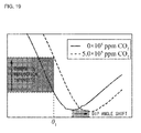
- Figure 19 is a graph comparing the dip angle shift ⁇ sp obtained in the gas sensor 1 when the CO 2 concentrations were made 0 ⁇ 10 5 [ppm] and 5.0 ⁇ 10 5 [ppm], and a ratio of change in reflection intensity.
- Figure 19 as a region in which the change in the reflection intensity is examined, attention was paid to the incidence angle ⁇ 1 at which the light intensity of the exit light L2 starts to reduce by a surface plasmon resonance phenomenon.
- the ratio of the change in the reflection intensity at the incidence angle ⁇ 1 is larger as compared with the dip angle shift ⁇ sp .
- the change amount of the reflection intensity which has a larger change amount as compared with the dip angle shift ⁇ sp is measured, and the gas in the outside air is detected based on the change amount of the reflection intensity, whereby even if a very small amount of gas is contained in the outside air, the gas can be easily detected with a larger change amount than the dip angle shift ⁇ sp .
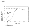
- Figure 20 shows a result of examining a change with time of a reflection intensity change rate from a time of starting to supply a gas with a CO 2 concentration of 6500 [ppm] to the isolation chamber 22.
- the reflection intensity change rate started to increase after a lapse of four minutes from the start of supply of the gas, and had a stable value after 28 minutes. Further, the reflection intensity change rate increased by 17[%] (from 10 [ ⁇ W] to 11.7 [ ⁇ W]). Furthermore, from Figure 20 , when the reflection intensity change rate was less than 2[%] (0.2 [ ⁇ W]), an unstable behavior was shown, in which the reflection intensity change rate is temporarily reduced or the like.
- the CO 2 concentration is stably detectable up to the CO 2 concentration of approximately 700 [ppm] (calculated from the experimental value of the reflection intensity change rate 17[%] with the CO 2 concentration of 6500 [ppm]).
- a wall portion 36a in a frame shape was formed from the lower silicon layer 32, a top plate portion 36b in a mesh shape having a plurality of through-holes 10 was formed from the upper silicon layer 34, and a first frame body 36 in which the top plate portion 36b was stacked on the wall portion 36a via the silicon oxide film 33a was produced, and was set as a device A.
- a substrate 41 formed from a photosensitive resin (KMPR-1035) was prepared.
- the substrate 41 was patterned by DRIE (Deep Reactive Ion Etching) that is a micropore forming technique, and a top plate portion 42b in a mesh shape having a plurality of through-holes 10 was produced.
- a frame-shaped wall portion 42a was formed along a frame of the top plate portion 42b, and a second frame body 42 was produced and was set as a device B.
- the heights h1 and h2 were respectively measured similarly with respect to the device A and the device B.
- the height h1 of the top plate portion 36b was 50 [ ⁇ m]
- the height h2 of the wall portion 36a was 300 [ ⁇ m]
- a liquid amount of the ionic liquid IL that was able to be injected into the internal space when the device A was fixedly attached onto the metal layer 7 of the gas sensor 1 was 21 [ ⁇ l].
- the height h1 of the top plate portion 42b was 250 [ ⁇ m]
- the height h2 of the wall portion 42a was 35 [ ⁇ m]
- a liquid amount of the ionic liquid IL that was able to be injected into the internal space when the device B was fixedly attached onto the metal layer 7 of the gas sensor 1 was 12 [ ⁇ l].
- the gas sensor 1 has the prism 6 including the metal layer 7 in the irradiation range of the incident light L1 that is caused to be incident from the light source, and changes the path of the incident light L1 at the metal layer 7 of the prism 6 to emit the incident light L1 as the exit light L2.
- the ionic liquid IL that can absorb the gas that is a target of detection is provided on the surface 7a of the metal layer 7, and the dielectric constant of the ionic liquid IL changes as a result of the ionic liquid IL absorbing the gas, and the light intensity of the exit light L2 changes by a surface plasmon resonance phenomenon that occurs in the metal layer 7 in accordance with the change of the dielectric constant.
- the change in the light intensity of the exit light L2 is measured, and the gas in outside air can be detected based on the tendency of the change in the light intensity of the exit light L2.
- the gas sensor 1 the light absorption path as in the prior art is not needed, and therefore, the size can be reduced correspondingly. Furthermore, in the gas sensor 1, even the gas with a small molecular weight such as CO 2 can be absorbed by the ionic liquid IL, and the dielectric constant of the ionic liquid IL that changes by absorbing the gas can be measured from the change in the reflection intensity that occurs by a surface plasmon resonance phenomenon in the metal layer 7. Therefore, the gas sensor 1 can detect even the gases with small molecular weights, which are conventionally difficult to measure.
- the gas sensor 1 of the present invention by only changing the kind of the ionic liquid IL provided on the metal layer 7, not only a gas with a small molecular weight but also gases with various molecular weights can be easily detected.
- the change in the dielectric constant of the ionic liquid IL can be measured according to the change in the light intensity that occurs by a surface plasmon resonance phenomenon in the metal layer 7, and therefore, the gas sensor 1 that is made of novel configuration that can detect a gas based on the change in the light intensity can be realized.
- a gas is detected based on the change amount of a dip angle that occurs by a surface plasmon resonance phenomenon in the metal layer 7, whereby a gas in outside air can be easily detected with the dip angle which has the smallest reflection intensity and easily recognizable as the measure. Furthermore, in the gas sensor 1, the frame body 3 that holds the ionic liquid IL on the metal layer 7 is provided, whereby even when an external force is applied to the metal layer 7, the ionic liquid IL can be kept to be held on the metal layer 7 stably.
- the present invention is not limited to the present embodiment, and can be carried out by being variously modified within the range of the gist of the present invention.
- the holding means the case of applying the frame body 3 in which a plurality of through-holes 10 are provided by being bored in the top plate portion 3b and causes the metal layer 7 to hold the ionic liquid IL by surrounding the ionic liquid IL with the top plate portion 3b and the wall portion 3a is described, but the present invention is not limited to this.
- a coating film that is formed from a material that allows a gas to pass through such as parylene, and causes the metal layer 7 to hold the ionic liquid IL by covering the entire surface of the semispherical ionic liquid IL that is dropped on the metal layer 7 may be applied.
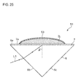
- a gas sensor 51 has a configuration in which a coating film 53 formed from, such as parylene that allows outside air to pass through, is formed on the metal layer 7, and the ionic liquid IL is stored in the coating film 53.
- the ionic liquid IL can be kept to be held on the metal layer 7 stably by the coating film 53 as the holding means.
- the gas sensor 51 can be produced by forming the coating film 53 on the metal layer 7 in advance from a coating material that allows outside air to pass through such as parylene, injecting the ionic liquid IL into the coating film 53 and sealing the ionic liquid IL.
- a configuration may be adopted, in which the metal layer 7 of the prism 6 is installed as a bottom surface in a box-shaped storage section in which the ionic liquid IL is stored, and the incident light L1 is emitted from the light source disposed diagonally above.
- Such gas sensors with the disposition relations of the prism 6 provided with the metal layers 7 and the ionic liquid IL properly changed may be applied in accordance with service conditions.
Landscapes
- Chemical & Material Sciences (AREA)
- Health & Medical Sciences (AREA)
- Life Sciences & Earth Sciences (AREA)
- Physics & Mathematics (AREA)
- Engineering & Computer Science (AREA)
- Immunology (AREA)
- Analytical Chemistry (AREA)
- Biochemistry (AREA)
- General Health & Medical Sciences (AREA)
- General Physics & Mathematics (AREA)
- Pathology (AREA)
- Combustion & Propulsion (AREA)
- Food Science & Technology (AREA)
- Medicinal Chemistry (AREA)
- Spectroscopy & Molecular Physics (AREA)
- Theoretical Computer Science (AREA)
- Mathematical Physics (AREA)
- Investigating Or Analysing Materials By Optical Means (AREA)
Abstract
Description
- The present invention relates to a gas sensor, and is suitable to be applied to detection of, for example, gases such as CO2 and NH3.
- In recent years, studies on gas sensors that detect CO2, for example, have been made at the requests for environmental monitoring. As a gas sensor of this kind, an infrared light absorption type gas sensor (NDIR: Nondispersive infrared detector) is known (for example, refer to Non Patent Literature 1). Further, as another gas sensor, a gas sensor using surface plasmon resonance (SPR) is known (for example, refer to Non Patent Literature 2).
-
- Non Patent Literature 1: S. Neethirajan, D. S. Jayas, and S. Sadistap, "Carbon dioxide (CO2) sensors for the agri-food industry-a review," Food Bioprocess Technol., vol.2, pp. 115-121, 2009.
- Non Patent Literature 2: Shozo Miwa, and Tsuyoshi Arakawa, "Selective gas detection by means of surface plasmon resonance sensors," Thin Solid Films, vol.281, pp. 466-468, 1996.
- However, in the infrared light absorption type gas sensor shown in the former, a light absorption path needs to be provided, and therefore, there arises the problem that the optical system is increased in size. Further, in the gas sensor in the latter does not require a light absorption path, and the size can be reduced correspondingly, but since the refractive index to be measured is substantially proportional to a molecular weight. Accordingly, it is difficult to measure, for example, the gas with a small molecular weight such as CO2. Therefore, realization of the gas sensor including a novel configuration that is also capable of detecting a gas with a small molecular weight has been desired.
- Consequently, the present invention is made in consideration of the above respect, and has an object to propose a gas sensor capable of performing detection of a gas with a novel configuration while achieving reduction in size.
- The present invention is a gas sensor that detects a gas that is a target of detection, the gas sensor including: a prism having a metal layer in an irradiation range of an incident light incident from a light source, and changing a path of the incident light at the metal layer to emit the incident light as an exit light; and a gas absorbing liquid provided on a surface of the metal layer, and capable of absorbing the gas, and is featured in that a dielectric constant of the gas absorbing liquid changes due to absorption of the gas in the gas absorbing liquid, and based on a change in light intensity of the exit light by a surface plasmon resonance phenomenon that occurs in the metal layer in response to the change in the dielectric constant, the gas is detected.
- According to the present invention, the light absorption path as in the prior art is not needed, and therefore, reduction in size can be achieved correspondingly. Also, a gas is absorbed in the gas absorbing liquid, and a dielectric constant of the gas absorbing liquid that changes by absorbing the gas can be measured according to the change in the light intensity that occurs by a surface plasmon resonance phenomenon in the metal layer. Thus, the gas sensor including a novel configuration that can detect the gas based on the change in the light intensity can be realized.
-
-
Figure 1 is a schematic view showing a configuration of a gas sensor according to the present invention. -
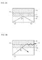
Figure 2 is a schematic view presented for explanation of a surface plasmon resonance phenomenon. -
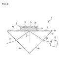
Figure 3 is a sectional view showing a sectional side configuration of the gas sensor according to the present invention. -
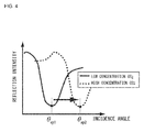
Figure 4 is a graph showing a relation of an incidence angle and a reflection intensity. -
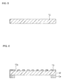
Figure 5 is a schematic view presented for explanation (1) of a method of producing a frame body. -
Figure 6 is a schematic view presented for explanation (2) of the method of producing the frame body. -
Figure 7 is a schematic view presented for explanation (3) of the method of producing the frame body. -
Figure 8 is a schematic view presented for explanation (4) of the method of producing the frame body. -
Figure 9 is a schematic view presented for explanation (1) of a method of producing the gas sensor. -
Figure 10 is a schematic view presented for explanation (2) of the method of producing the gas sensor. -
Figure 11 is a schematic view presented for explanation (3) of the method of producing the gas sensor. -
Figure 12 is a schematic view presented for explanation (4) of the method of producing the gas sensor. -
Figure 13 is a schematic view presented for explanation (5) of the method of producing the gas sensor. -
Figure 14 is a photograph showing a configuration of a gas sensor that was actually produced. -
Figure 15 is a schematic view showing an entire configuration of an experimental apparatus. -
Figure 16 is a graph showing relations of incidence angles and reflection intensity in the case of a mixture gas of CO2 and outside air, and in the case of only outside air. -
Figure 17 is a graph showing a relation of a dip angle shift and a CO2 concentration. -
Figure 18 is a graph showing a change with time of the dip angle shift. -
Figure 19 is a graph showing relations of the dip angle shifts and changes in reflection intensity in the case of a mixture gas of CO2 and outside air, and in the case of only outside air. -
Figure 20 is a graph showing a change with time of a reflection intensity change rate. -
Figure 21 is a schematic view showing a method of producing a device A. -
Figure 22 is a schematic view showing a method of producing a device B. -
Figure 23 is a table showing respective dimensions of the device A and the device B. -
Figure 24 is a table showing experimental results of gas sensors using the device A and the device B respectively. -
Figure 25 is a sectional view showing a sectional side configuration of a gas sensor according to another embodiment. -
- 1, 51
- Gas sensor
- 3
- Frame body (holding means)
- 6
- Prism
- 7
- Metal layer
- IL
- Ionic liquid (gas adsorbing liquid)
- 53
- Coating film (holding means)
- Hereinafter, embodiments of the present invention will be described in detail based on the drawings.
- In
Figure 1 , a gas sensor according to the present invention is denoted by 1, and thegas sensor 1 is configured to be able to detect, for example, CO2, as a target of detection. In practice, thegas sensor 1 has a configuration having aprism 6 on which an incident light L1 from a light source not illustrated is incident, including ametal layer 7 in an irradiation range of the incident light L1 that is incident on theprism 6, and provided with an ionic liquid IL on asurface 7a of themetal layer 7. - In practice, the
prism 6 is formed from, for example, a transparent material such as glass and acryl, and allows the incident light L1 emitted from the light source to pass through an inside thereof. Further, in the case of the embodiment, theprism 6 is formed into a substantially triangular prism shape, so that the incident light L1 can be incident on aquadrangular incidence plane 6b. Theprism 6 is configured such that the incident light L1 incident from theincidence plane 6b passes through the inside thereof and can reach themetal layer 7 that is deposited on anotherquadrangular irradiation plane 6a, and can exit as an exit light L2 from another quadrangular exit plane after the path of the incident light L1 is changed at themetal layer 7. - Further, in the
metal layer 7, aframe body 3 configured by awall portion 3a and atop plate portion 3b is fixedly attached to asurface 7a, and the ionic liquid IL is kept on thesurface 7a by theframe body 3. In practice, theframe body 3 is formed from silicon, for example, and a height thereof is set at 250 [µm]. Further, in theframe body 3, the plate-shapedtop plate portion 3b is provided at a frame-shapedwall portion 3a of one side set at 10 [mm], an internal space surrounded by thesurface 7a of themetal layer 7, thewall portion 3a, and thetop plate portion 3b is formed, so that the ionic liquid IL is kept in the internal space. - Here, the
frame body 3 has a configuration in which a plurality of through-holes 10 are provided by being bored in thetop plate portion 3b, and as shown in an area ER1 in which a part of thegas sensor 1 ofFigure 1 is enlarged, the ionic liquid IL in the internal space is exposed to an outside from the through-holes 10, so that the ionic liquid IL in the internal space can contact outside air around an outside of theframe body 3. Thereby, the ionic liquid IL held in theframe body 3 can absorb a gas that is a target of detection contained in the outside air. Incidentally, in theframe body 3, the through-holes 10 bored in thetop plate portion 3b are microscopic, and therefore, the ionic liquid IL keeps staying in theframe body 3 by the surface tension without leaking out from the through-holes 10 and can be held stably on thesurface 7a of themetal layer 7, though the ionic liquid IL injected into the internal space is exposed to outside air by the through-holes 10. - Here, the
metal layer 7 on which the ionic liquid IL is placed is formed from an Au or Cr/Au material, for example, and has a film thickness set at approximately 50 nm. When themetal layer 7 is irradiated with the incident light L1 passing through the inside of theprism 6 at an incidence angle θ, themetal layer 7 can change the path by reflecting the incident light L1. Note that here, the incidence angle θ refers to an angle of the incident light L1 with respect to a perpendicular line orthogonal to the plane of themetal layer 7. In addition to the above configuration, themetal layer 7 is configured to be able to generate a surface plasmon resonance phenomenon in accordance with a state of a dielectric constant of the ionic liquid IL placed on thesurface 7a, when the incident light L1 is emitted. - Incidentally, a surface plasmon resonance phenomenon refers to a phenomenon in which when the incident light L1 is caused to be incident on the
prism 6, evanescent waves that are always generated in the prism surface on which themetal layer 7 is deposited, and surface plasmon waves that are excited in thesurface 7a of themetal layer 7 resonate, and light intensity (hereinafter, also called reflection intensity) of the exit light L2 that reflects at themetal layer 7 decreases. - Here, the ionic liquid IL as a gas absorbing liquid is formed from, for example, [EMIM][BF4] (1-ethyl-3-methylimidazolium tetrafluoroborate), [BMIM][BF4] (1-butyl-3-methylimidazolium tetrafluoroborate), [BMIM][PF6] (1-butyl-3-methylimidazolium hexafluorophosphate), or [OMIM][Br] (1-n-octyl-3-methylimidazolium bromide), and other than the above, [Hmpy][Tf2N], [HMIM][Tf2N], [BMIM][Tf2N], [C6H4F9min][Tf2N], [AMIM][BF4], [Pabim] [Bf4], [Am-im][DCA], [Am-im][BF4], [BMIM][BF4]+PVDF, [C3NH2mim][CF6SO3]+PTFE, [C3NH2mim][Tf2N]+PTFE, [H2NC3H6mim][Tf2N]+cross-linked Pylon66, P[VBBI][BF4], P[MABI][BF4], P[VBBI][Tf2N], P[VBTMA][BF4], P[MATMA][BF4] or the like, and in accordance with the kind of a gas to be a target of detection, the ionic liquid that can absorb the gas can be properly selected.
- Here, when the
gas sensor 1 that can detect CO2, for example, is made, [EMIM][BF4], [BMIM][BF4], [BMIM][PF6], [Hmpy][Tf2N], [HMIM][Tf2N], [BMIM][Tf2N], [C6H4F9mim][Tf2N], [AMIM][BF4], [Pabim][BF4], [Am-im][DCA], [Am-im][BF4], [BMIM][BF4]+PVDF, [C3NH2mim][CF6SO3]+PTFE, [C3NH2mim][Tf2N]+PTFE, [H2NC3H6mim][Tf2N]+cross-linked Nylon66, P[VBBI][BF4], P[MABI][BF4], P[VBBI][Tf2N], P[VBTMA][BF4], P[MATMA][BF4] or the like that can absorb CO2 is used as the ionic liquid IL. Further, when thegas sensor 1 that can detect NH3 is made, ionic liquids that absorb water in general, such as [EMIM][BF4] capable of absorbing NH3 are used as the ionic liquid IL. Note that to the ionic liquid IL, for example, PEI (polyethyleneimine) may be added. - Further, in the aforementioned embodiment, the case in which the ionic liquid IL is applied as the gas absorbing liquid is described, but the present invention is not limited to this, and, for example, various other gas absorbing liquids such as hydroxide aqueous solutions of an alkali metal and an alkaline earth metal may be applied. Note that when hydroxide aqueous solutions of an alkali metal and an alkaline earth metal are used as the gas absorbing liquids, the gas absorbing liquids can absorb CO2, and therefore, the gas sensor the detection target of which is CO2 can be realized.
- The ionic liquid IL like this is configured such that when the ionic liquid IL absorbs the gas that is a target of detection, the dielectric constant thereof can change in accordance with an absorption amount of the gas. The
metal layer 7 on which the ionic liquid IL is placed is configured such that when the dielectric constant changes in the ionic liquid IL, the light intensity (reflection intensity) of the exit light L2 can change in accordance with the change in the dielectric constant. - In practice, as shown in
Figure 2A , when the gas that is a target of detection is not contained in outside air, for example, change in the dielectric constant by the gas does not occur in the ionic liquid IL, and themetal layer 7 can reflect the incident light L1 emitted at the incidence angle θ and can allow the incident light L1 to exit with a predetermined light intensity as the exit light L2. Meanwhile, as shown inFigure 2B , when the gas that is a target of detection is contained in outside air, for example, the dielectric constant of the ionic liquid IL changes due to the gas, and even when the incident light L1 is caused to be incident on themetal layer 7 at the same incidence angle θ, the surface plasmon wave L3 that is generated in a plane direction of themetal layer 7 by receiving the influence of the change of the dielectric constant resonates with an evanescent wave, and can decrease the light intensity (reflection intensity) of the exit light L2. - As shown in
Figure 3 , the gas sensor includes an intensimeter C that measures the light intensity of the exit light L2 at a position facing anexit plane 6c, and can measure a change in the light intensity of the exit light L2 that occurs due to a surface plasmon resonance phenomenon by the intensimeter C. Thegas sensor 1 is configured to measure the change in the light intensity of the exit light L2 by the surface plasmon resonance phenomenon that occurs on themetal layer 7 in accordance with the change in the dielectric constant of the ionic liquid IL by the intensimeter C, and to be able to detect the gas contained in the outside air based on the measurement result thereof. - In practice, as shown in
Figure 4 , when the concentration of CO2 that is a target of detection is low, the measurement result that the reflection intensity decreases due to a surface plasmon resonance phenomenon at an incidence angle θsp1, for example, is obtained in thisgas sensor 1. In contrast with this, when the concentration of CO2 that is the target of detection is high, the measurement result that the reflection intensity decreases by a surface plasmon resonance phenomenon at an incidence angle θsp2 that differs from the incidence angle θsp1 is obtained in thegas sensor 1, a dip angle at which the reflection intensity decreases by a surface plasmon resonance phenomenon can change from the incidence angle θsp1 to the incidence angle θsp2 in accordance with the concentration of CO2. Thus, in thisgas sensor 1, it can be detected whether or not CO2 is contained in outside air by a predetermined concentration or more, based on the change in the light intensity of the exit light L2 by the surface plasmon resonance phenomenon that occurs in themetal layer 7 in accordance with the change in the dielectric constant of the ionic liquid IL. Further, the dip angle at which the reflection intensity decreases by a surface plasmon resonance phenomenon changes in accordance with the concentration of CO2. From this, in thisgas sensor 1, the concentration of CO2 contained in outside air can be estimated based on the change amount of the light intensity of the exit light L2 and the change amount of the dip angle. - Next, a method of producing the
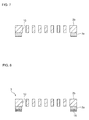
gas sensor 1 of the present invention will be described. Here, a method of producing the frame body is described, and then, the method of producing the gas sensor using the frame body will be described in sequence. First of all, as shown inFigure 5 , asilicon substrate 12 of a thickness of 250 [µm] to be thetop plate portion 3b is prepared, and as shown inFigure 6 , a resistlayer 13 having through-holes 13a of each 500 [µm] in length and width at intervals of 650 [µm] is formed on one surface of thesilicon substrate 12. Further, apart from this, thewall portion 3a is formed on the other surface of thesilicon substrate 12 from a resist material (KMPR-1035 made by Nippon Kayaku Co., Ltd.) of a thickness of 30 [µm], for example, by spin coating and patterning. - Next, the
silicon substrate 12 is etched with use of the resistlayer 13 provided on the one surface of thesilicon substrate 12, and then, the resistlayer 13 is removed, and thetop plate portion 3b having the plurality of through-holes 10 is formed as shown inFigure 7 . Hence, theframe body 3 to which the frame-shapedwall portion 3a is fixedly attached to the other surface along the frame of thetop plate portion 3b in a mesh shape is formed. Next, as shown inFigure 8 , anadhesive layer 14 formed from polydimethylsiloxane (PDMS), for example, is formed on a bottom surface portion of thewall portion 3a to fixedly attach theframe body 3 to themetal layer 7 on theprism 6 that will be described later. - Next, the method of producing the
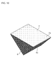
gas sensor 1 using theframe body 3 produced as above will be described. Here, theprism 6 formed from glass in a triangular prism shape (for example, made from SF11 glass, with a refractive index of 1.774 with a light wavelength of 675 [nm]) as shown inFigure 9 is prepared first of all, and thereafter, themetal layer 7 formed from CR/Au (2 [nm]/50 [nm]) as shown inFigure 10 is deposited on only theirradiation plane 6a flat and formed into a quadrangular shape. Note that the film thickness of themetal layer 7 is optimized to maximize the sensitivity for surface plasmon resonance. - Next, as shown in
Figure 11 , thewall portion 3a of theframe body 3 produced in advance is placed on themetal layer 7 on theprism 6, and then heated by a heater at 110[°C] for five minutes to allow thewall portion 3a of theframe body 3 to be fixedly attached to themetal layer 7 by theadhesive layer 14. Next, as shown inFigure 12 , the ionic liquid IL is injected into the internal space of theframe body 3 from the through-holes 10 of theframe body 3 via injection means 15 such as a dropping pipette, and thereby thegas sensor 1 of the present invention as shown inFigure 13 can be produced. - Next, various verification tests will be described. Here, in accordance with the production method described above, as shown in
Figure 14 , thegas sensor 1 was produced, in which themetal layer 7 was kept substantially horizontal, and the ionic liquid IL was exposed to an outside from the through-holes 10 of 500 [µm] × 500 [µm] of theframe body 3 while 10 [µl] of the ionic liquid IL was held in theframe body 3 of 10 [mm] × 10 [mm]. Note that an opening ratio to the outside of theframe body 3 in thegas sensor 1 was set at 60[%]. - Subsequently, with use of an
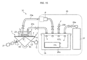
experimental apparatus 20 as shown inFigure 15 , verification was conducted on whether or not CO2 that is a target of detection can be detected in thegas sensor 1. In practice, theexperimental apparatus 20 includes agas supply device 25, and a gas which was adjusted to have a predetermined CO2 concentration was supplied to anisolation chamber 22 provided in thegas sensor 1 from thegas supply device 25. Here, thegas supply device 25 includes achamber 26, agas storage section 27 and a pump P, CO2 was supplied into thechamber 26 from thegas storage section 27, and a gas adjusted to have a predetermined CO2 concentration was generated in thechamber 26 with a detected concentration of aconcentration sensor 26a in thechamber 26 as a measure. - Further, the
gas supply device 25 recovered the gas to thechamber 26 from theisolation chamber 22 via arecovery tube 23b while supplying the gas in thechamber 26 to theisolation chamber 22 via asupply tube 23a from thechamber 26 by a pump P, so as to circulate the gas. Note that thechamber 26 was provided with anexhaust tube 28b, and the gas in thechamber 26 was discharged to the outside from theexhaust tube 28b in accordance with necessity. Theisolation chamber 22 was formed by a housing and was installed on themetal layer 7 in such a manner as to cover theentire frame body 3 on themetal layer 7 in thegas sensor 1 to isolate the ionic liquid IL of thegas sensor 1 from the outside air. Thereby, in this experiment, the ionic liquid IL of thegas sensor 1 was disposed in the gas of a predetermined CO2 concentration generated in thechamber 26. - Further, in this
experimental apparatus 20, alight source 21 that emits a TM polarized wave of a wavelength of 675 [nm] was provided, and the TM polarized wave was emitted onto theincidence plane 6b of theprism 6 as the incident light L1. In practice, the laser light from a laser diode was polarized by a polarizing plate, the incident light L1 that was made a spot of 0.3 [nm] by a slit was generated by thelight source 21, and emitted to theprism 6. Further, here, the incident light L1 was emitted toward themetal layer 7 from theincidence plane 6b of theprism 6 of thegas sensor 1 and the path of the incident light Li was changed at themetal layer 7 of thegas sensor 1, and thereby being emitted from theexit plane 6c as the exit light L2. Further, the intensimeter C was disposed at a position facing theexit plane 6c, and the light intensity of the exit light L2 was measured by the intensimeter C. - With use of the
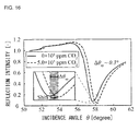
experimental apparatus 20 as above, a gas (namely, a gas that does not contain CO2) with the concentration of CO2 of 0 × 105 [ppm] was filled in theisolation chamber 22 first of all, the incident light L1 is emitted to theprism 6 from thelight source 21 after stabilization, after which, the incidence angle θ of the incident light L1 was changed from 50[°] to 60[°] with angle resolution of 0.05[°], and the light intensity (reflection intensity) of the exit light L2 at this time was measured by the intensimeter C. Further, after theisolation chamber 22 was refreshed, a gas with the concentration of CO2 of 5.0 × 10⁵ [ppm] was filled in theisolation chamber 22, the incident light L1 is emitted to theprism 6 from thelight source 21 after stabilization, after which, the incidence angle θ of the incident light L1 was changed from 50[°] to 60[°] with angle resolution of 0.05[°], and the light intensity (reflection intensity) of the exit light L2 at this time was measured by the intensimeter C. - Consequently, a result as shown in
Figure 16 was obtained. FromFigure 16 , when attention is paid to the dip angle at which the lowest reflection intensity appears, when the CO2 concentration in the gas becomes high, a dip angle shift Δθsp representing a shift amount of the dip angle becomes 0.3[°], and it has been able to be confirmed that the dip angle shifts. Next, when the dip angle shifts Δθsp at the time of making the CO2 concentration 1.0 × 10⁵ [ppm], 2.5 × 10⁵ [ppm] and 5.0 × 10⁵ [ppm] were examined, a result as shown inFigure 17 was obtained. FromFigure 17 , it was confirmed that in thisgas sensor 1, as the CO2 concentration becomes higher, the dip angle shift Δθsp also becomes larger, and therefore, it was confirmed that by measuring the value of the dip angle shift Δθsp, the CO2 concentration in the outside air also can be estimated. - Next, when a response time until the dip angle shift Δθsp changed after the CO2 concentration was changed was examined, a result as shown in
Figure 18 was obtained. FromFigure 18 , it was found out that when the CO2 gas of 5.0 × 10⁵ [ppm] is supplied into theisolation chamber 22, the dip angle shift Δθsp is stabilized after 13 minutes of the supply of the CO2 gas, it was further found out that with the CO2 gas of 1.0 × 10⁵ [ppm] and the CO2 gas of 2.5 × 10⁵ [ppm], average response times are respectively 7 minutes and 12 minutes, and it was confirmed that gas detection can be performed by minutes. - Here,
Figure 19 is a graph comparing the dip angle shift Δθsp obtained in thegas sensor 1 when the CO2 concentrations were made 0×105 [ppm] and 5.0×10⁵ [ppm], and a ratio of change in reflection intensity. InFigure 19 , as a region in which the change in the reflection intensity is examined, attention was paid to the incidence angle θ1 at which the light intensity of the exit light L2 starts to reduce by a surface plasmon resonance phenomenon. As shown inFigure 19 , as the measurement result obtained from thegas sensor 1, it was found out that the ratio of the change in the reflection intensity at the incidence angle θ1 is larger as compared with the dip angle shift Δθsp. From this, it was found out that in thegas sensor 1, the change amount of the reflection intensity which has a larger change amount as compared with the dip angle shift Δθsp is measured, and the gas in the outside air is detected based on the change amount of the reflection intensity, whereby even if a very small amount of gas is contained in the outside air, the gas can be easily detected with a larger change amount than the dip angle shift Δθsp. - Further,
Figure 20 shows a result of examining a change with time of a reflection intensity change rate from a time of starting to supply a gas with a CO2 concentration of 6500 [ppm] to theisolation chamber 22. The reflection intensity change rate started to increase after a lapse of four minutes from the start of supply of the gas, and had a stable value after 28 minutes. Further, the reflection intensity change rate increased by 17[%] (from 10 [µW] to 11.7 [µW]). Furthermore, fromFigure 20 , when the reflection intensity change rate was less than 2[%] (0.2 [µW]), an unstable behavior was shown, in which the reflection intensity change rate is temporarily reduced or the like. Accordingly, it was found out that in thegas sensor 1, detecting the CO2 concentration by using the reflection intensity change rate of 2[%] or more in which the reflection intensity change rate stably increases in proportion to the CO2 concentration is also preferable as one example thereof. In this case, the CO2 concentration is stably detectable up to the CO2 concentration of approximately 700 [ppm] (calculated from the experimental value of the reflection intensity change rate 17[%] with the CO2 concentration of 6500 [ppm]). - Next, two kinds of frame bodies that have different sizes of the internal spaces were prepared, and in two kinds of gas sensors provided with the frame bodies, reaction times (response times) in which the reflection intensity change rates changed when the CO2 concentration was changed were examined. In practice, as shown in
Figure 21 , first of all, anSOI wafer 31 in which anupper silicon layer 34 was provided on alower silicon layer 32 via asilicon oxide film 33 was prepared. Next, thelower silicon layer 32 and theupper silicon layer 34 were processed by DRIE (Deep Reactive Ion Etching) that is a micropore forming technique, and then were conducted a cleaning by hydrogen fluoride (HF). After the cleaning, awall portion 36a in a frame shape was formed from thelower silicon layer 32, atop plate portion 36b in a mesh shape having a plurality of through-holes 10 was formed from theupper silicon layer 34, and afirst frame body 36 in which thetop plate portion 36b was stacked on thewall portion 36a via thesilicon oxide film 33a was produced, and was set as a device A. - Further, apart from the above, as shown in
Figure 22 , asubstrate 41 formed from a photosensitive resin (KMPR-1035) was prepared. Thesubstrate 41 was patterned by DRIE (Deep Reactive Ion Etching) that is a micropore forming technique, and atop plate portion 42b in a mesh shape having a plurality of through-holes 10 was produced. Further, a frame-shapedwall portion 42a was formed along a frame of thetop plate portion 42b, and asecond frame body 42 was produced and was set as a device B. - As shown in
Figure 23 , for example, with a height of thetop plate portion 3b being set as h1, and a height of thewall portion 3a being set as h2, the heights h1 and h2 were respectively measured similarly with respect to the device A and the device B. As a result, as in a table shown inFigure 23 , in the device A, the height h1 of thetop plate portion 36b was 50 [µm], the height h2 of thewall portion 36a was 300 [µm], and a liquid amount of the ionic liquid IL that was able to be injected into the internal space when the device A was fixedly attached onto themetal layer 7 of thegas sensor 1 was 21 [µl]. Meanwhile, with respect to the device B, the height h1 of thetop plate portion 42b was 250 [µm], the height h2 of thewall portion 42a was 35 [µm], and a liquid amount of the ionic liquid IL that was able to be injected into the internal space when the device B was fixedly attached onto themetal layer 7 of thegas sensor 1 was 12 [µl]. - Subsequently, by using of the
experimental apparatus 20, with respect to the gas sensors provided with the device A and the device B respectively as above, when the gases the CO2 concentrations of which were 10[%], 25[%] and 50[%] were respectively supplied to theisolation chambers 22, and the response times until the dip angles were generated after start of gas supply were examined, a result as shown inFigure 24 was obtained. Note that inFigure 24 , a total height of the heights h1 and h2 is described as D [µm]. From the result ofFigure 24 , it was confirmed that in the gas sensor provided with the device B with a smaller liquid amount of the ionic liquid IL, the response time is shorter by 56[%] on average, and the response time becomes expedited. Accordingly, it was confirmed that when a gas sensor is produced, in which a response time is short with respect to the gas that is a target of detection, the liquid amount of the ionic liquid IL can be made small. - In the above configuration, the
gas sensor 1 has theprism 6 including themetal layer 7 in the irradiation range of the incident light L1 that is caused to be incident from the light source, and changes the path of the incident light L1 at themetal layer 7 of theprism 6 to emit the incident light L1 as the exit light L2. Further, in thegas sensor 1, the ionic liquid IL that can absorb the gas that is a target of detection is provided on thesurface 7a of themetal layer 7, and the dielectric constant of the ionic liquid IL changes as a result of the ionic liquid IL absorbing the gas, and the light intensity of the exit light L2 changes by a surface plasmon resonance phenomenon that occurs in themetal layer 7 in accordance with the change of the dielectric constant. Thereby, in thegas sensor 1, the change in the light intensity of the exit light L2 is measured, and the gas in outside air can be detected based on the tendency of the change in the light intensity of the exit light L2. - Further, in the
gas sensor 1, the light absorption path as in the prior art is not needed, and therefore, the size can be reduced correspondingly. Furthermore, in thegas sensor 1, even the gas with a small molecular weight such as CO2 can be absorbed by the ionic liquid IL, and the dielectric constant of the ionic liquid IL that changes by absorbing the gas can be measured from the change in the reflection intensity that occurs by a surface plasmon resonance phenomenon in themetal layer 7. Therefore, thegas sensor 1 can detect even the gases with small molecular weights, which are conventionally difficult to measure. - Furthermore, in the
gas sensor 1 of the present invention, by only changing the kind of the ionic liquid IL provided on themetal layer 7, not only a gas with a small molecular weight but also gases with various molecular weights can be easily detected. Like this, in the present invention, the change in the dielectric constant of the ionic liquid IL can be measured according to the change in the light intensity that occurs by a surface plasmon resonance phenomenon in themetal layer 7, and therefore, thegas sensor 1 that is made of novel configuration that can detect a gas based on the change in the light intensity can be realized. - Further, in the
gas sensor 1, a gas is detected based on the change amount of a dip angle that occurs by a surface plasmon resonance phenomenon in themetal layer 7, whereby a gas in outside air can be easily detected with the dip angle which has the smallest reflection intensity and easily recognizable as the measure. Furthermore, in thegas sensor 1, theframe body 3 that holds the ionic liquid IL on themetal layer 7 is provided, whereby even when an external force is applied to themetal layer 7, the ionic liquid IL can be kept to be held on themetal layer 7 stably. - Note that the present invention is not limited to the present embodiment, and can be carried out by being variously modified within the range of the gist of the present invention. In the embodiment described above, as the holding means, the case of applying the
frame body 3 in which a plurality of through-holes 10 are provided by being bored in thetop plate portion 3b and causes themetal layer 7 to hold the ionic liquid IL by surrounding the ionic liquid IL with thetop plate portion 3b and thewall portion 3a is described, but the present invention is not limited to this. A coating film that is formed from a material that allows a gas to pass through such as parylene, and causes themetal layer 7 to hold the ionic liquid IL by covering the entire surface of the semispherical ionic liquid IL that is dropped on themetal layer 7 may be applied. - In practice, as in
Figure 25 showing a gas sensor by assigning the components corresponding to those inFigure 3 with the same reference signs, agas sensor 51 has a configuration in which acoating film 53 formed from, such as parylene that allows outside air to pass through, is formed on themetal layer 7, and the ionic liquid IL is stored in thecoating film 53. In this case, in thegas sensor 51, even if an external force is applied to themetal layer 7 and themetal layer 7 is tilted or the like, the ionic liquid IL can be kept to be held on themetal layer 7 stably by thecoating film 53 as the holding means. Incidentally, thegas sensor 51 can be produced by forming thecoating film 53 on themetal layer 7 in advance from a coating material that allows outside air to pass through such as parylene, injecting the ionic liquid IL into thecoating film 53 and sealing the ionic liquid IL. - Furthermore, as another embodiment, a configuration may be adopted, in which the
metal layer 7 of theprism 6 is installed as a bottom surface in a box-shaped storage section in which the ionic liquid IL is stored, and the incident light L1 is emitted from the light source disposed diagonally above. Such gas sensors with the disposition relations of theprism 6 provided with themetal layers 7 and the ionic liquid IL properly changed may be applied in accordance with service conditions.
Claims (6)
- A gas sensor that detects a gas that is a target of detection, comprising:a prism having a metal layer in an irradiation range of an incident light incident from a light source, and changing a path of the incident light at the metal layer to emit the incident light as an exit light; anda gas absorbing liquid provided on a surface of the metal layer, and capable of absorbing the gas,wherein a dielectric constant of the gas absorbing liquid changes due to absorption of the gas in the gas absorbing liquid, and based on a change in light intensity of the exit light by a surface plasmon resonance phenomenon that occurs in the metal layer in response to the change in the dielectric constant, the gas is detected.
- The gas sensor according to claim 1,
wherein the gas is detected based on a change amount of a dip angle that occurs by the surface plasmon resonance phenomenon when the gas absorbing liquid absorbs the gas. - The gas sensor according to claim 1,
wherein the gas is detected based on a change amount of reflection intensity that occurs by the surface plasmon resonance phenomenon when the gas absorbing liquid absorbs the gas. - The gas sensor according to any one of claims 1 to 3,
further comprising holding means that covers the gas absorbing liquid, and causes the gas absorbing liquid to be held on the metal layer. - The gas sensor according to any one of claims 1 to 4,
wherein the gas absorbing liquid is an ionic liquid. - The gas sensor according to any one of claims 1 to 4,
wherein the gas absorbing liquid is a hydroxide aqueous solution of an alkali metal and an alkaline earth metal.
Applications Claiming Priority (2)
| Application Number | Priority Date | Filing Date | Title |
|---|---|---|---|
| JP2012004964A JP5777063B2 (en) | 2012-01-13 | 2012-01-13 | Gas sensor |
| PCT/JP2012/083880 WO2013105450A1 (en) | 2012-01-13 | 2012-12-27 | Gas sensor |
Publications (3)
| Publication Number | Publication Date |
|---|---|
| EP2803974A1 true EP2803974A1 (en) | 2014-11-19 |
| EP2803974A4 EP2803974A4 (en) | 2015-12-30 |
| EP2803974B1 EP2803974B1 (en) | 2020-04-15 |
Family
ID=48781406
Family Applications (1)
| Application Number | Title | Priority Date | Filing Date |
|---|---|---|---|
| EP12865116.3A Active EP2803974B1 (en) | 2012-01-13 | 2012-12-27 | Gas sensor |
Country Status (6)
| Country | Link |
|---|---|
| US (1) | US9546948B2 (en) |
| EP (1) | EP2803974B1 (en) |
| JP (1) | JP5777063B2 (en) |
| KR (1) | KR20140090258A (en) |
| CN (1) | CN103998918A (en) |
| WO (1) | WO2013105450A1 (en) |
Cited By (1)
| Publication number | Priority date | Publication date | Assignee | Title |
|---|---|---|---|---|
| WO2021124046A1 (en) * | 2019-12-20 | 2021-06-24 | 3M Innovative Properties Company | Nanohole array sensor elements and sensors including the same |
Families Citing this family (15)
| Publication number | Priority date | Publication date | Assignee | Title |
|---|---|---|---|---|
| EP2853889B1 (en) * | 2013-09-26 | 2016-03-02 | ams International AG | Integrated circuit with CO2 sensor, composition and manufacturing method of such an IC |
| KR101667316B1 (en) * | 2014-04-25 | 2016-10-19 | 포미주식회사 | System for ventilating windowless barn |
| US10067108B2 (en) | 2015-05-13 | 2018-09-04 | Elemental Sensor Llc | Device for detecting volatile organic compounds |
| US10463275B2 (en) * | 2015-08-09 | 2019-11-05 | Elemental Sensor Llc | Device for capturing and concentrating volatile organic compounds |
| US12188893B2 (en) | 2016-08-30 | 2025-01-07 | Analog Devices International Unlimited Company | Electrochemical sensor, and a method of forming an electrochemical sensor |
| US11268927B2 (en) | 2016-08-30 | 2022-03-08 | Analog Devices International Unlimited Company | Electrochemical sensor, and a method of forming an electrochemical sensor |
| US10620151B2 (en) | 2016-08-30 | 2020-04-14 | Analog Devices Global | Electrochemical sensor, and a method of forming an electrochemical sensor |
| CN106645025A (en) * | 2016-12-27 | 2017-05-10 | 吉林大学 | Online detector for automobile exhaust component content |
| US11022579B2 (en) | 2018-02-05 | 2021-06-01 | Analog Devices International Unlimited Company | Retaining cap |
| JP7124579B2 (en) * | 2018-09-06 | 2022-08-24 | 日本精工株式会社 | gas sensor |
| US11231365B2 (en) * | 2019-07-08 | 2022-01-25 | Hanwha Systems Co., Ltd. | Apparatus and method for infrared imaging |
| KR102141357B1 (en) * | 2019-08-12 | 2020-08-05 | 울산과학기술원 | Method for detection and identification of chemical agent gas and sensor for detection and identification of chemical agent gas |
| CN110940863B (en) * | 2019-10-23 | 2020-11-17 | 上海大学 | Resonance sensor based on integrated active amplifier chip |
| JP2021117002A (en) * | 2020-01-22 | 2021-08-10 | 学校法人 創価大学 | Hetero-core fiber optic carbon dioxide sensor |
| JP7443894B2 (en) * | 2020-03-31 | 2024-03-06 | 横河電機株式会社 | Spectroscopic analyzer, operating method of spectroscopic analyzer, and program |
Family Cites Families (31)
| Publication number | Priority date | Publication date | Assignee | Title |
|---|---|---|---|---|
| JPS60125558A (en) | 1983-12-09 | 1985-07-04 | Kuraray Co Ltd | Gas sensor |
| JPH0679009B2 (en) | 1985-11-22 | 1994-10-05 | 株式会社東芝 | Chemical sensor |
| JP3167022B2 (en) | 1988-11-18 | 2001-05-14 | 新電元工業株式会社 | Gas sensor |
| JPH03237350A (en) | 1990-02-14 | 1991-10-23 | Terumo Corp | Ph sensor and production thereof |
| DE4445668C2 (en) * | 1994-12-21 | 1997-05-15 | Euroferm Gmbh I Gr | Device for measuring the partial pressure of gases dissolved in liquids in systems for carrying out biotechnological or food technology processes |
| US7142296B2 (en) * | 2000-10-30 | 2006-11-28 | Sru Biosystems, Inc. | Method and apparatus for detecting biomolecular interactions |
| US7875434B2 (en) * | 2000-10-30 | 2011-01-25 | Sru Biosystems, Inc. | Label-free methods for performing assays using a colorimetric resonant reflectance optical biosensor |
| US8154093B2 (en) | 2002-01-16 | 2012-04-10 | Nanomix, Inc. | Nano-electronic sensors for chemical and biological analytes, including capacitance and bio-membrane devices |
| JP2004085392A (en) | 2002-08-27 | 2004-03-18 | Fujitsu Ltd | Field effect transistor chemical sensor using elemental carbon linear structure |
| US7927822B2 (en) * | 2002-09-09 | 2011-04-19 | Sru Biosystems, Inc. | Methods for screening cells and antibodies |
| EP1664724A4 (en) | 2003-09-12 | 2007-05-02 | Nanomix Inc | Carbon dioxide nanoelectronic sensor |
| US7187446B2 (en) * | 2004-07-26 | 2007-03-06 | Fuji Photo Film Co., Ltd. | Measuring apparatus |
| JP2006125860A (en) * | 2004-10-26 | 2006-05-18 | Fujikura Ltd | Surface plasmon sensor and surface plasmon measuring device |
| JP4891550B2 (en) | 2005-02-10 | 2012-03-07 | 独立行政法人科学技術振興機構 | N-type transistor, n-type transistor sensor, and n-type transistor channel manufacturing method |
| US20060234391A1 (en) * | 2005-02-18 | 2006-10-19 | University Of Rochester | Optical sensor based on resonant porous silicon structures |
| US7879619B2 (en) * | 2005-10-07 | 2011-02-01 | Tianwei Jing | Apparatus for detecting one or more substances and method of detecting a substance |
| WO2008030666A2 (en) * | 2006-07-25 | 2008-03-13 | The Board Of Trustees Of The University Of Illinois | Multispectral plasmonic crystal sensors |
| WO2009011368A1 (en) * | 2007-07-19 | 2009-01-22 | Gunze Limited | Solid ion-conducting material, electrochemical device utilizing the solid ion-conducting material, and method for production of the electrochemical device |
| JP4926865B2 (en) * | 2007-07-20 | 2012-05-09 | シャープ株式会社 | Surface plasmon sensor |
| CN101398399A (en) * | 2007-09-26 | 2009-04-01 | 中国科学院大连化学物理研究所 | Quartz crystal resonator, preparation and application thereof |
| US8506887B2 (en) * | 2008-10-17 | 2013-08-13 | Vanderbilt University | Porous membrane waveguide sensors and sensing systems therefrom for detecting biological or chemical targets |
| KR101052504B1 (en) * | 2008-11-27 | 2011-08-01 | 한국과학기술연구원 | High Resolution Surface Plasmon Resonance Sensor and Sensor System Using It |
| JP2010192599A (en) | 2009-02-17 | 2010-09-02 | Olympus Corp | Method of forming insulation film in field effect transistor using carbon nano material and field effect transistor using carbon nano material |
| JP5369755B2 (en) * | 2009-02-25 | 2013-12-18 | 株式会社豊田中央研究所 | Gas sensor |
| JP2010203838A (en) * | 2009-03-02 | 2010-09-16 | Sonac Kk | Optical waveguide sensor |
| CN101504360A (en) * | 2009-03-03 | 2009-08-12 | 中国科学院光电技术研究所 | Organic gas sensing method |
| JP2010261793A (en) * | 2009-05-01 | 2010-11-18 | Kurabo Ind Ltd | Method and apparatus for measuring dissolved substance content in liquid, and etching solution regeneration system |
| US8711356B2 (en) * | 2010-02-25 | 2014-04-29 | Stichting Imec Nederland | Gas sensor with a porous layer that detectably affects a surface lattice resonant condition of a nanoparticle array |
| KR100977292B1 (en) * | 2010-04-30 | 2010-08-23 | 지에스건설 주식회사 | Spr gas sensing device manufacturing method using molecularly imprinted polymer |
| JPWO2011155179A1 (en) * | 2010-06-10 | 2013-08-01 | コニカミノルタ株式会社 | Analysis element chip |
| CN102072929B (en) * | 2010-11-25 | 2013-02-06 | 厦门出入境检验检疫局检验检疫技术中心 | Formaldehyde gas sensor |
-
2012
- 2012-01-13 JP JP2012004964A patent/JP5777063B2/en active Active
- 2012-12-27 KR KR1020147015736A patent/KR20140090258A/en not_active Ceased
- 2012-12-27 US US14/368,396 patent/US9546948B2/en active Active
- 2012-12-27 CN CN201280060964.4A patent/CN103998918A/en active Pending
- 2012-12-27 EP EP12865116.3A patent/EP2803974B1/en active Active
- 2012-12-27 WO PCT/JP2012/083880 patent/WO2013105450A1/en not_active Ceased
Cited By (1)
| Publication number | Priority date | Publication date | Assignee | Title |
|---|---|---|---|---|
| WO2021124046A1 (en) * | 2019-12-20 | 2021-06-24 | 3M Innovative Properties Company | Nanohole array sensor elements and sensors including the same |
Also Published As
| Publication number | Publication date |
|---|---|
| KR20140090258A (en) | 2014-07-16 |
| JP2013145137A (en) | 2013-07-25 |
| US20150009503A1 (en) | 2015-01-08 |
| WO2013105450A1 (en) | 2013-07-18 |
| EP2803974A4 (en) | 2015-12-30 |
| CN103998918A (en) | 2014-08-20 |
| US9546948B2 (en) | 2017-01-17 |
| JP5777063B2 (en) | 2015-09-09 |
| EP2803974B1 (en) | 2020-04-15 |
Similar Documents
| Publication | Publication Date | Title |
|---|---|---|
| US9546948B2 (en) | Gas sensor | |
| JP5462892B2 (en) | Total reflection attenuation optical probe and aqueous solution spectrometer using the same | |
| JP4911606B2 (en) | Total reflection attenuation optical probe and aqueous solution spectrometer using the same | |
| DeGrandpre et al. | Long path fiber-optic sensor for evanescent field absorbance measurements | |
| US9523637B2 (en) | Thermal selectivity multivariate optical computing | |
| WO2012161067A1 (en) | Measuring unit and gas analyzer | |
| JP4958220B2 (en) | Total reflection attenuation optical probe and aqueous solution spectrometer using the same | |
| WO2005088278A1 (en) | Functionalised surface sensing apparatus and methods | |
| Halfacre et al. | Using tunable infrared laser direct absorption spectroscopy for ambient hydrogen chloride detection: HCl-TILDAS | |
| CN110234983A (en) | Measure the apparatus and method of material position in the spatial distribution and/or fluid of compound and its mixture concentration in fluid | |
| JP4500967B2 (en) | Substance adsorption detection method and sensor | |
| JP2017116449A (en) | Sensor chip package, sensor chip package array, gas detector, and gas detecting method | |
| US20090066957A1 (en) | Method and Apparatus for Sensing a Target Substance by Analysing Time Series of Said Target Substance | |
| Porter et al. | Mid-infrared laser-absorption diagnostic for vapor-phase fuel mole fraction and liquid fuel film thickness | |
| WO2019008271A1 (en) | Device for the in situ extraction of dissolved gas and corresponding measuring apparatus | |
| JP2015102455A (en) | Sensor device and measuring method | |
| US20140240709A1 (en) | Advanced mass gauge sensor | |
| Taga et al. | Fiber optic evanescent field sensors for gaseous species using MIR transparent fibers | |
| JP2009058483A (en) | Method and sensor for detecting substance adsorption | |
| Pérez | New Approaches to Fiber Sensors Based on Tilted Fiber Bragg Gratings | |
| JP2021117002A (en) | Hetero-core fiber optic carbon dioxide sensor | |
| JPH09329553A (en) | Optical sensor for detection chemical substance dissolved or dispersed in water | |
| HK1126854A (en) | Total reflection attenuation optical probe and aqueous solution spectrometric device | |
| Medina | Instrument Development and Measurements of the Atmospheric Pollutants Sulfur Dioxide, Nitrate Radical, and Nitrous Acid by Cavity Ring-down Spectroscopy and Cavity Enhanced Absorption Spectroscopy | |
| MX2007005838A (en) | Surface plasmon resonance device for detecting hydrocarbon vapours. |
Legal Events
| Date | Code | Title | Description |
|---|---|---|---|
| PUAI | Public reference made under article 153(3) epc to a published international application that has entered the european phase |
Free format text: ORIGINAL CODE: 0009012 |
|
| 17P | Request for examination filed |
Effective date: 20140624 |
|
| AK | Designated contracting states |
Kind code of ref document: A1 Designated state(s): AL AT BE BG CH CY CZ DE DK EE ES FI FR GB GR HR HU IE IS IT LI LT LU LV MC MK MT NL NO PL PT RO RS SE SI SK SM TR |
|
| DAX | Request for extension of the european patent (deleted) | ||
| RA4 | Supplementary search report drawn up and despatched (corrected) |
Effective date: 20151126 |
|
| RIC1 | Information provided on ipc code assigned before grant |
Ipc: G01N 21/552 20140101AFI20151120BHEP Ipc: G01N 33/00 20060101ALI20151120BHEP |
|
| GRAP | Despatch of communication of intention to grant a patent |
Free format text: ORIGINAL CODE: EPIDOSNIGR1 |
|
| STAA | Information on the status of an ep patent application or granted ep patent |
Free format text: STATUS: GRANT OF PATENT IS INTENDED |
|
| INTG | Intention to grant announced |
Effective date: 20191028 |
|
| GRAS | Grant fee paid |
Free format text: ORIGINAL CODE: EPIDOSNIGR3 |
|
| GRAA | (expected) grant |
Free format text: ORIGINAL CODE: 0009210 |
|
| STAA | Information on the status of an ep patent application or granted ep patent |
Free format text: STATUS: THE PATENT HAS BEEN GRANTED |
|
| AK | Designated contracting states |
Kind code of ref document: B1 Designated state(s): AL AT BE BG CH CY CZ DE DK EE ES FI FR GB GR HR HU IE IS IT LI LT LU LV MC MK MT NL NO PL PT RO RS SE SI SK SM TR |
|
| REG | Reference to a national code |
Ref country code: GB Ref legal event code: FG4D Ref country code: CH Ref legal event code: EP |
|
| REG | Reference to a national code |
Ref country code: DE Ref legal event code: R096 Ref document number: 602012069366 Country of ref document: DE |
|
| REG | Reference to a national code |
Ref country code: IE Ref legal event code: FG4D |
|
| REG | Reference to a national code |
Ref country code: AT Ref legal event code: REF Ref document number: 1257903 Country of ref document: AT Kind code of ref document: T Effective date: 20200515 |
|
| REG | Reference to a national code |
Ref country code: NL Ref legal event code: MP Effective date: 20200415 |
|
| REG | Reference to a national code |
Ref country code: LT Ref legal event code: MG4D |
|
| PG25 | Lapsed in a contracting state [announced via postgrant information from national office to epo] |
Ref country code: FI Free format text: LAPSE BECAUSE OF FAILURE TO SUBMIT A TRANSLATION OF THE DESCRIPTION OR TO PAY THE FEE WITHIN THE PRESCRIBED TIME-LIMIT Effective date: 20200415 Ref country code: PT Free format text: LAPSE BECAUSE OF FAILURE TO SUBMIT A TRANSLATION OF THE DESCRIPTION OR TO PAY THE FEE WITHIN THE PRESCRIBED TIME-LIMIT Effective date: 20200817 Ref country code: SE Free format text: LAPSE BECAUSE OF FAILURE TO SUBMIT A TRANSLATION OF THE DESCRIPTION OR TO PAY THE FEE WITHIN THE PRESCRIBED TIME-LIMIT Effective date: 20200415 Ref country code: NL Free format text: LAPSE BECAUSE OF FAILURE TO SUBMIT A TRANSLATION OF THE DESCRIPTION OR TO PAY THE FEE WITHIN THE PRESCRIBED TIME-LIMIT Effective date: 20200415 Ref country code: LT Free format text: LAPSE BECAUSE OF FAILURE TO SUBMIT A TRANSLATION OF THE DESCRIPTION OR TO PAY THE FEE WITHIN THE PRESCRIBED TIME-LIMIT Effective date: 20200415 Ref country code: NO Free format text: LAPSE BECAUSE OF FAILURE TO SUBMIT A TRANSLATION OF THE DESCRIPTION OR TO PAY THE FEE WITHIN THE PRESCRIBED TIME-LIMIT Effective date: 20200715 Ref country code: GR Free format text: LAPSE BECAUSE OF FAILURE TO SUBMIT A TRANSLATION OF THE DESCRIPTION OR TO PAY THE FEE WITHIN THE PRESCRIBED TIME-LIMIT Effective date: 20200716 Ref country code: IS Free format text: LAPSE BECAUSE OF FAILURE TO SUBMIT A TRANSLATION OF THE DESCRIPTION OR TO PAY THE FEE WITHIN THE PRESCRIBED TIME-LIMIT Effective date: 20200815 |
|
| REG | Reference to a national code |
Ref country code: AT Ref legal event code: MK05 Ref document number: 1257903 Country of ref document: AT Kind code of ref document: T Effective date: 20200415 |
|
| PG25 | Lapsed in a contracting state [announced via postgrant information from national office to epo] |
Ref country code: BG Free format text: LAPSE BECAUSE OF FAILURE TO SUBMIT A TRANSLATION OF THE DESCRIPTION OR TO PAY THE FEE WITHIN THE PRESCRIBED TIME-LIMIT Effective date: 20200715 Ref country code: LV Free format text: LAPSE BECAUSE OF FAILURE TO SUBMIT A TRANSLATION OF THE DESCRIPTION OR TO PAY THE FEE WITHIN THE PRESCRIBED TIME-LIMIT Effective date: 20200415 Ref country code: RS Free format text: LAPSE BECAUSE OF FAILURE TO SUBMIT A TRANSLATION OF THE DESCRIPTION OR TO PAY THE FEE WITHIN THE PRESCRIBED TIME-LIMIT Effective date: 20200415 Ref country code: HR Free format text: LAPSE BECAUSE OF FAILURE TO SUBMIT A TRANSLATION OF THE DESCRIPTION OR TO PAY THE FEE WITHIN THE PRESCRIBED TIME-LIMIT Effective date: 20200415 |
|
| PG25 | Lapsed in a contracting state [announced via postgrant information from national office to epo] |
Ref country code: AL Free format text: LAPSE BECAUSE OF FAILURE TO SUBMIT A TRANSLATION OF THE DESCRIPTION OR TO PAY THE FEE WITHIN THE PRESCRIBED TIME-LIMIT Effective date: 20200415 |
|
| REG | Reference to a national code |
Ref country code: DE Ref legal event code: R097 Ref document number: 602012069366 Country of ref document: DE |
|
| PG25 | Lapsed in a contracting state [announced via postgrant information from national office to epo] |
Ref country code: EE Free format text: LAPSE BECAUSE OF FAILURE TO SUBMIT A TRANSLATION OF THE DESCRIPTION OR TO PAY THE FEE WITHIN THE PRESCRIBED TIME-LIMIT Effective date: 20200415 Ref country code: SM Free format text: LAPSE BECAUSE OF FAILURE TO SUBMIT A TRANSLATION OF THE DESCRIPTION OR TO PAY THE FEE WITHIN THE PRESCRIBED TIME-LIMIT Effective date: 20200415 Ref country code: IT Free format text: LAPSE BECAUSE OF FAILURE TO SUBMIT A TRANSLATION OF THE DESCRIPTION OR TO PAY THE FEE WITHIN THE PRESCRIBED TIME-LIMIT Effective date: 20200415 Ref country code: AT Free format text: LAPSE BECAUSE OF FAILURE TO SUBMIT A TRANSLATION OF THE DESCRIPTION OR TO PAY THE FEE WITHIN THE PRESCRIBED TIME-LIMIT Effective date: 20200415 Ref country code: CZ Free format text: LAPSE BECAUSE OF FAILURE TO SUBMIT A TRANSLATION OF THE DESCRIPTION OR TO PAY THE FEE WITHIN THE PRESCRIBED TIME-LIMIT Effective date: 20200415 Ref country code: RO Free format text: LAPSE BECAUSE OF FAILURE TO SUBMIT A TRANSLATION OF THE DESCRIPTION OR TO PAY THE FEE WITHIN THE PRESCRIBED TIME-LIMIT Effective date: 20200415 Ref country code: ES Free format text: LAPSE BECAUSE OF FAILURE TO SUBMIT A TRANSLATION OF THE DESCRIPTION OR TO PAY THE FEE WITHIN THE PRESCRIBED TIME-LIMIT Effective date: 20200415 Ref country code: DK Free format text: LAPSE BECAUSE OF FAILURE TO SUBMIT A TRANSLATION OF THE DESCRIPTION OR TO PAY THE FEE WITHIN THE PRESCRIBED TIME-LIMIT Effective date: 20200415 |
|
| PLBE | No opposition filed within time limit |
Free format text: ORIGINAL CODE: 0009261 |
|
| STAA | Information on the status of an ep patent application or granted ep patent |
Free format text: STATUS: NO OPPOSITION FILED WITHIN TIME LIMIT |
|
| PG25 | Lapsed in a contracting state [announced via postgrant information from national office to epo] |
Ref country code: SK Free format text: LAPSE BECAUSE OF FAILURE TO SUBMIT A TRANSLATION OF THE DESCRIPTION OR TO PAY THE FEE WITHIN THE PRESCRIBED TIME-LIMIT Effective date: 20200415 Ref country code: PL Free format text: LAPSE BECAUSE OF FAILURE TO SUBMIT A TRANSLATION OF THE DESCRIPTION OR TO PAY THE FEE WITHIN THE PRESCRIBED TIME-LIMIT Effective date: 20200415 |
|
| 26N | No opposition filed |
Effective date: 20210118 |
|
| PG25 | Lapsed in a contracting state [announced via postgrant information from national office to epo] |
Ref country code: SI Free format text: LAPSE BECAUSE OF FAILURE TO SUBMIT A TRANSLATION OF THE DESCRIPTION OR TO PAY THE FEE WITHIN THE PRESCRIBED TIME-LIMIT Effective date: 20200415 |
|
| REG | Reference to a national code |
Ref country code: CH Ref legal event code: PL |
|
| GBPC | Gb: european patent ceased through non-payment of renewal fee |
Effective date: 20201227 |
|
| PG25 | Lapsed in a contracting state [announced via postgrant information from national office to epo] |
Ref country code: MC Free format text: LAPSE BECAUSE OF FAILURE TO SUBMIT A TRANSLATION OF THE DESCRIPTION OR TO PAY THE FEE WITHIN THE PRESCRIBED TIME-LIMIT Effective date: 20200415 |
|
| REG | Reference to a national code |
Ref country code: BE Ref legal event code: MM Effective date: 20201231 |
|
| PG25 | Lapsed in a contracting state [announced via postgrant information from national office to epo] |
Ref country code: LU Free format text: LAPSE BECAUSE OF NON-PAYMENT OF DUE FEES Effective date: 20201227 Ref country code: IE Free format text: LAPSE BECAUSE OF NON-PAYMENT OF DUE FEES Effective date: 20201227 |
|
| PG25 | Lapsed in a contracting state [announced via postgrant information from national office to epo] |
Ref country code: CH Free format text: LAPSE BECAUSE OF NON-PAYMENT OF DUE FEES Effective date: 20201231 Ref country code: GB Free format text: LAPSE BECAUSE OF NON-PAYMENT OF DUE FEES Effective date: 20201227 Ref country code: LI Free format text: LAPSE BECAUSE OF NON-PAYMENT OF DUE FEES Effective date: 20201231 |
|
| PG25 | Lapsed in a contracting state [announced via postgrant information from national office to epo] |
Ref country code: TR Free format text: LAPSE BECAUSE OF FAILURE TO SUBMIT A TRANSLATION OF THE DESCRIPTION OR TO PAY THE FEE WITHIN THE PRESCRIBED TIME-LIMIT Effective date: 20200415 Ref country code: MT Free format text: LAPSE BECAUSE OF FAILURE TO SUBMIT A TRANSLATION OF THE DESCRIPTION OR TO PAY THE FEE WITHIN THE PRESCRIBED TIME-LIMIT Effective date: 20200415 Ref country code: CY Free format text: LAPSE BECAUSE OF FAILURE TO SUBMIT A TRANSLATION OF THE DESCRIPTION OR TO PAY THE FEE WITHIN THE PRESCRIBED TIME-LIMIT Effective date: 20200415 |
|
| PG25 | Lapsed in a contracting state [announced via postgrant information from national office to epo] |
Ref country code: MK Free format text: LAPSE BECAUSE OF FAILURE TO SUBMIT A TRANSLATION OF THE DESCRIPTION OR TO PAY THE FEE WITHIN THE PRESCRIBED TIME-LIMIT Effective date: 20200415 |
|
| PG25 | Lapsed in a contracting state [announced via postgrant information from national office to epo] |
Ref country code: BE Free format text: LAPSE BECAUSE OF NON-PAYMENT OF DUE FEES Effective date: 20201231 |
|
| PGFP | Annual fee paid to national office [announced via postgrant information from national office to epo] |
Ref country code: DE Payment date: 20251104 Year of fee payment: 14 |
|
| PGFP | Annual fee paid to national office [announced via postgrant information from national office to epo] |
Ref country code: FR Payment date: 20251110 Year of fee payment: 14 |