EP2803962A1 - Pyroelektrische Sensorvorrichtung, Verfahren zum Herstellen derselben und Verfahren zum pyroelektrischen Erfassen von Wärmestrahlung - Google Patents
Pyroelektrische Sensorvorrichtung, Verfahren zum Herstellen derselben und Verfahren zum pyroelektrischen Erfassen von Wärmestrahlung Download PDFInfo
- Publication number
- EP2803962A1 EP2803962A1 EP14164932.7A EP14164932A EP2803962A1 EP 2803962 A1 EP2803962 A1 EP 2803962A1 EP 14164932 A EP14164932 A EP 14164932A EP 2803962 A1 EP2803962 A1 EP 2803962A1
- Authority
- EP
- European Patent Office
- Prior art keywords
- pyroelectric
- temperature control
- control device
- detection device
- thermoelectric temperature
- Prior art date
- Legal status (The legal status is an assumption and is not a legal conclusion. Google has not performed a legal analysis and makes no representation as to the accuracy of the status listed.)
- Withdrawn
Links
Images


Classifications
-
- G—PHYSICS
- G01—MEASURING; TESTING
- G01J—MEASUREMENT OF INTENSITY, VELOCITY, SPECTRAL CONTENT, POLARISATION, PHASE OR PULSE CHARACTERISTICS OF INFRARED, VISIBLE OR ULTRAVIOLET LIGHT; COLORIMETRY; RADIATION PYROMETRY
- G01J5/00—Radiation pyrometry, e.g. infrared or optical thermometry
- G01J5/10—Radiation pyrometry, e.g. infrared or optical thermometry using electric radiation detectors
- G01J5/34—Radiation pyrometry, e.g. infrared or optical thermometry using electric radiation detectors using capacitors, e.g. pyroelectric capacitors
-
- G—PHYSICS
- G01—MEASURING; TESTING
- G01J—MEASUREMENT OF INTENSITY, VELOCITY, SPECTRAL CONTENT, POLARISATION, PHASE OR PULSE CHARACTERISTICS OF INFRARED, VISIBLE OR ULTRAVIOLET LIGHT; COLORIMETRY; RADIATION PYROMETRY
- G01J5/00—Radiation pyrometry, e.g. infrared or optical thermometry
- G01J5/02—Constructional details
- G01J5/0225—Shape of the cavity itself or of elements contained in or suspended over the cavity
- G01J5/024—Special manufacturing steps or sacrificial layers or layer structures
-
- G—PHYSICS
- G01—MEASURING; TESTING
- G01J—MEASUREMENT OF INTENSITY, VELOCITY, SPECTRAL CONTENT, POLARISATION, PHASE OR PULSE CHARACTERISTICS OF INFRARED, VISIBLE OR ULTRAVIOLET LIGHT; COLORIMETRY; RADIATION PYROMETRY
- G01J5/00—Radiation pyrometry, e.g. infrared or optical thermometry
- G01J5/02—Constructional details
- G01J5/06—Arrangements for eliminating effects of disturbing radiation; Arrangements for compensating changes in sensitivity
- G01J5/061—Arrangements for eliminating effects of disturbing radiation; Arrangements for compensating changes in sensitivity by controlling the temperature of the apparatus or parts thereof, e.g. using cooling means or thermostats
-
- G—PHYSICS
- G01—MEASURING; TESTING
- G01J—MEASUREMENT OF INTENSITY, VELOCITY, SPECTRAL CONTENT, POLARISATION, PHASE OR PULSE CHARACTERISTICS OF INFRARED, VISIBLE OR ULTRAVIOLET LIGHT; COLORIMETRY; RADIATION PYROMETRY
- G01J5/00—Radiation pyrometry, e.g. infrared or optical thermometry
- G01J5/02—Constructional details
- G01J5/08—Optical arrangements
- G01J5/0881—Compact construction
-
- G—PHYSICS
- G01—MEASURING; TESTING
- G01J—MEASUREMENT OF INTENSITY, VELOCITY, SPECTRAL CONTENT, POLARISATION, PHASE OR PULSE CHARACTERISTICS OF INFRARED, VISIBLE OR ULTRAVIOLET LIGHT; COLORIMETRY; RADIATION PYROMETRY
- G01J5/00—Radiation pyrometry, e.g. infrared or optical thermometry
- G01J5/80—Calibration
-
- G—PHYSICS
- G01—MEASURING; TESTING
- G01J—MEASUREMENT OF INTENSITY, VELOCITY, SPECTRAL CONTENT, POLARISATION, PHASE OR PULSE CHARACTERISTICS OF INFRARED, VISIBLE OR ULTRAVIOLET LIGHT; COLORIMETRY; RADIATION PYROMETRY
- G01J5/00—Radiation pyrometry, e.g. infrared or optical thermometry
- G01J2005/0077—Imaging
-
- G—PHYSICS
- G01—MEASURING; TESTING
- G01J—MEASUREMENT OF INTENSITY, VELOCITY, SPECTRAL CONTENT, POLARISATION, PHASE OR PULSE CHARACTERISTICS OF INFRARED, VISIBLE OR ULTRAVIOLET LIGHT; COLORIMETRY; RADIATION PYROMETRY
- G01J5/00—Radiation pyrometry, e.g. infrared or optical thermometry
- G01J5/02—Constructional details
- G01J5/06—Arrangements for eliminating effects of disturbing radiation; Arrangements for compensating changes in sensitivity
- G01J5/061—Arrangements for eliminating effects of disturbing radiation; Arrangements for compensating changes in sensitivity by controlling the temperature of the apparatus or parts thereof, e.g. using cooling means or thermostats
- G01J2005/062—Peltier
-
- G—PHYSICS
- G01—MEASURING; TESTING
- G01J—MEASUREMENT OF INTENSITY, VELOCITY, SPECTRAL CONTENT, POLARISATION, PHASE OR PULSE CHARACTERISTICS OF INFRARED, VISIBLE OR ULTRAVIOLET LIGHT; COLORIMETRY; RADIATION PYROMETRY
- G01J5/00—Radiation pyrometry, e.g. infrared or optical thermometry
- G01J5/10—Radiation pyrometry, e.g. infrared or optical thermometry using electric radiation detectors
- G01J5/34—Radiation pyrometry, e.g. infrared or optical thermometry using electric radiation detectors using capacitors, e.g. pyroelectric capacitors
- G01J2005/345—Arrays
Definitions
- the present invention relates to a pyroelectric sensor device, to a method for producing a pyroelectric sensor device, to a method for pyroelectric detection of thermal radiation and to a corresponding computer program product.
- Pyroelectric materials are often used as sensor materials for infrared sensors and cameras, for example for a Focal Plane Array (FPA).
- FPA Focal Plane Array
- Pyroelectric crystals exhibit spontaneous internal electrical polarization measurable as a voltage across electrodes disposed on opposite sides of a sample of the pyroelectric material. At constant sample temperature, this internal polarization is neutralized by mobile charges on the surface of the sample; Thus, no voltage difference is measured by the electrodes. If the temperature suddenly changes to a new value, the internal polarization changes, which leads to a measurable voltage difference.
- conventional pyroelectric detectors usually do not measure a direct current (DC) signal. The sensor signal is modulated in time to be detected.
- DC direct current
- the US 5,075,549 A discloses a pyroelectric detector using electronic chopping.
- the polarization of the pyroelectric crystal is modulated by an alternating electric field.
- a pyroelectric sensor without chopper or a pyroelectric infrared camera without chopper can be provided for the detection of thermal radiation, and in particular a mechanical transducer device or modulation device, also known as a mechanical chopper, can be avoided or eliminated.
- a temperature modulation without chopper for a pyroelectric detector provided to measure a DC signal or DC signal can.
- the temperature modulation of the pyroelectric detector is controlled by a cooling / heating element based on the thermoelectric effect, e.g. B. Peltier effect or Seebeck effect realized.
- embodiments of the present invention make it possible to provide a pyroelectric sensor without choppers for a variety of applications and also for detecting stationary scenes. Due to the avoidance of chopping or a chopper, in particular a mechanical chopper, a number of moving parts can be reduced and thus a more compact design of the sensor can be achieved and costs can be saved. Because of the properties of pyroelectric materials in combination with the avoidance of choppers, it is therefore possible to create versatile detectors which have a high sensitivity for a broad spectrum from the visible range to the terahertz range and high efficiency. Such a pyroelectric sensor without chopper or a pyroelectric infrared camera without chopper can, due to superior properties, inter alia, in applications from the fields Driver assistance, night vision, surveillance, building security and people counting are used.
- a time-modulated light source can be dispensed with.
- applications such as people counting and gesture recognition where no defined light source is meaningfully available, both a movement of objects, and thus a temperature change, as well as a static scene can be detected.
- additional software algorithms for compensating the missing information can be dispensed with.
- no mechanical transducer device or modulation device also known as a mechanical chopper, is more likely to be used to modulate the incident light.
- mechanical vibrations no longer need to be used.
- the pyroelectric detection device may have at least one pyroelectric sensor element.
- a pyroelectric sensor element may in this case comprise a pyroelectric material, such as, for example, lead zirconate titanate (PZT) or lithium tantalum crystal, and two electrodes, between which the pyroelectric material is arranged.
- PZT lead zirconate titanate
- lithium tantalum crystal two electrodes, between which the pyroelectric material is arranged.
- thermoelectric temperature control device can be controllable in order to repeatedly cool the pyroelectric detection device in order to effect the thermal cycling.
- thermoelectric temperature control means can be controlled by means of a drive signal to the To cool pyroelectric detection means for effecting the thermal cycling in an adjustable or modulatable cycle.
- a first cycle phase with activated cooling operation and a second cycle phase with deactivated cooling operation of the thermoelectric temperature control device can alternate.
- thermoelectric temperature control device may be controllable in order to repeatedly heat the pyroelectric detection device in order to effect the thermal cycling.
- the thermoelectric temperature control device may comprise at least one Peltier element or at least one thin-film layer of thermoelectric material.
- the thermoelectric temperature control device can be thermally and / or mechanically coupled directly or indirectly thermally to the pyroelectric detection device.
- Such an embodiment has the advantage that the thermoelectric temperature control and thus the temperature modulation can be realized in a particularly simple manner and the thermoelectric temperature control is particularly easy to thermally coupled with the pyroelectric detection device.
- a heat-conducting substrate may also be arranged between the pyroelectric detection device and the thermoelectric temperature control device.
- the pyroelectric detection device and the thermoelectric temperature control device can be thermally coupled to one another by means of the heat-conducting substrate.
- the heat-conducting substrate is a substrate of a thermally conductive material.
- the heat-conducting substrate may comprise a semiconductor membrane, for example a silicon membrane.
- the pyroelectric detection device may comprise a plurality of pyroelectric sensor elements, which are thermally coupled to the thermoelectric temperature control device by means of a common heat conducting substrate.
- the heat-conducting substrate is a substrate of a thermally conductive material.
- the heat-conducting substrate may comprise a semiconductor membrane, for example a silicon membrane.
- a first electrical circuit may be provided for reading out at least one sensor signal representing the thermal radiation from the pyroelectric detection device.
- the first electrical circuit can be designed to forward the at least one sensor signal, to further process it and / or to determine the thermal radiation using the at least one sensor signal.
- determination of the heat radiation using the first electric circuit can be advantageously realized.
- thermoelectric temperature control device a second electrical circuit for driving the thermoelectric temperature control device may be provided to effect the thermal cycling of the pyroelectric detection device.
- the second electrical circuit can be designed to output to the thermoelectric temperature control device a drive signal which is suitable for effecting the thermal cycling of the pyroelectric detection device by means of the thermoelectric temperature control device.
- the thermal cycling or temperature modulation by means of the second electrical circuit can be advantageously enabled or realized.
- the manufacturing method can be advantageously carried out to produce an embodiment of the above-mentioned pyroelectric sensor device.
- the pyroelectric detection method may be advantageously carried out in conjunction with an embodiment of the aforementioned pyroelectric sensor device to detect thermal radiation.
- Also of advantage is a computer program product with program code which is stored on a machine-readable medium such as a semiconductor memory, a hard disk memory or an optical memory and is used to carry out a method of pyroelectric heat radiation detection mentioned above when the program is run on a computer or a device is performed.
- a machine-readable medium such as a semiconductor memory, a hard disk memory or an optical memory
- Such a device may be part of a control device or the like.
- the apparatus may be configured to perform the steps of an above-mentioned detection method.
- the apparatus may comprise means adapted to carry out each step of a method mentioned above.
- the device may have an interface, which may be formed in hardware and / or software.
- the interfaces can be part of a so-called system ASIC, for example, which contains a wide variety of functions of the device.
- the interfaces are their own integrated circuits or at least partially consist of discrete components.
- the interfaces may be software modules that are present, for example, on a microcontroller in addition to other software modules.
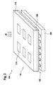
- Fig. 1 shows a schematic representation of a pyroelectric sensor device 100 according to an embodiment of the present invention.
- the pyroelectric sensor device 100 has a pyroelectric detection device 110 for detecting heat radiation and a thermoelectric temperature control device 120.
- the thermoelectric temperature control device 120 is thermally coupled to the pyroelectric detection device 110.
- the thermoelectric temperature control device 120 is also controllable in order to bring about a thermal cycling of the pyroelectric detection device 110.
- thermoelectric temperature control device 120 is controllable in order to repeatedly cool the pyroelectric detection device 110 in order to effect the thermal cycling. According to an alternative embodiment, the thermoelectric temperature control device may be controllable in order to repeatedly heat the pyroelectric detection device in order to effect the thermal cycling. According to one exemplary embodiment, the thermoelectric temperature control device 120 has at least one Peltier element or at least one thin-film layer of thermoelectric material.
- a heat-conducting substrate 130 is arranged between the pyroelectric detection device 110 and the thermoelectric temperature control device 120.
- the pyroelectric detection device 110 and the thermoelectric temperature control device 120 are thermally coupled to one another by means of the heat-conducting substrate 130.
- the heat-conducting substrate 130 comprises a semiconductor membrane, for example a silicon membrane.
- the pyroelectric detection device 110 has a plurality of pyroelectric sensor elements, which are thermally coupled to the thermoelectric temperature control device 120 by means of a common heat-conducting substrate 130.
- the sensor apparatus 100 has a first electrical circuit 140 for reading out at least one sensor signal representing the thermal radiation from the pyroelectric detector 110.
- the first electrical circuit 140 is connected by means of electrical lines to terminals of the pyroelectric detection device 110.
- the sensor device 100 has a second electrical circuit 150 for driving the thermoelectric temperature control device 120 in order to effect the thermal cycling of the pyroelectric detection device 110.
- the second electrical circuit 150 is connected by means of electrical lines to terminals of the thermoelectric temperature control device 120.
- Fig. 2 shows a schematic sectional view of a pyroelectric sensor device 100 according to an embodiment of the present invention.
- pyroelectric sensor device 100 corresponds or similar to in Fig. 1 shown pyroelectric sensor device.
- the representation in Fig. 2 shows the pyroelectric sensor device 100 in more detail than Fig. 1 and in a sectional view.
- thermoelectric sensor device 100 Shown are the pyroelectric sensor device 100, the pyroelectric detection device 110, the thermoelectric temperature control 120, the thruleitsubstrat 130 or a Si membrane, the first electrical circuit 140, a directional arrow indicating the second electrical circuit 150, a pyroelectric crystal 212 and pyroelectric material, a first electrode 214, a second electrode 216, thermoelectric material 222, two TED electrodes 224 (TED, thermoelectric device) of the thermoelectric temperature control device 120, two contact layers 226, a carrier substrate 260 and infrared radiation IR , Furthermore, an area of predominantly negative electrical charge N and a region of predominantly positive electrical charge P in the thermoelectric material 222 are shown by way of example.
- thermoelectric temperature control device 120 shown.
- directional arrows symbolically show a flow of electrical current in the TED electrodes 224.
- the pyroelectric detector 110 includes the pyroelectric crystal 212 disposed between the first electrode 214 and the second electrode 216.
- the first electrode 214 is arranged facing the incident heat radiation IR
- the second electrode 216 is disposed away from the incident heat radiation IR.
- the first electrode 214 and the second electrode 216 of the pyroelectric detector 110 are electrically connected to the first electrical circuit 140.
- the first electrical circuit 140 is designed to read at least one sensor signal from the pyroelectric detection device 110.
- the first electrical circuit 140 is configured to measure the heat radiation signal or IR signal. For example, a video signal typically requires 30 to 60 frames per second.
- the pyroelectric detection device 110 is conceivable, for example, a use of a commercially available pyroelectric detector or detector array, z. B. PZT-based or based on lead zirconate titanate.
- a pyroelectric detector is formed by means of a semiconductor process or MEMS (micro-electro-mechanical system) process in order to build up a silicon membrane.
- MEMS micro-electro-mechanical system
- Such a silicon membrane may act as the heat-conducting substrate 130 according to one embodiment.
- the heat conduction substrate 130 is disposed between the pyroelectric detector 110 and the thermoelectric temperature controller 120.
- the second electrode 216 of the pyroelectric detection device 110 is connected to the heat-conducting substrate 130.
- the thermoelectric temperature control device 120 has the thermoelectric material 222, the TED electrodes 224 and the contact layers 226.
- a first of the TED electrodes 224 is connected to the heat conducting substrate 130.
- a second of the TED electrodes 224 is connected to the carrier substrate 260.
- the thermoelectric temperature control device 120 is arranged between the heat-conducting substrate 130 and the carrier substrate 260.
- the Thermoelectric material 222 is disposed between the TED electrodes 224.
- the contact layers 226 are arranged between the thermoelectric material 223 and the TED electrodes 224.
- thermoelectric temperature control 120 is according to one embodiment, a commercially available thermoelectric device (TED) z. Based on materials such as Bi 2 Te 3 , Bi 2 Se 3 , PbTe or the like.
- thermoelectric tempering device 120 is thus attached to a side facing away from the incident heat radiation IR side of the pyroelectric detection device 110 and the pyroelectric detector.
- the attachment of the thermoelectric tempering device 120 to the pyroelectric detection device 110 takes place, for example, by soldering, wafer bonding, chip bonding, thermal compression, gluing or other joining techniques.
- the thermoelectric temperature control device 120 acts as a cooling element and / or heating element in the sensor device 100.
- thermoelectric temperature control device 120 is constructed using thin-film technology.
- thermoelectric layers are constructed by a sputtering process, CVD process or using a discrete component such as a Peltier element.
- the thermoelectric layers may be applied directly to the pyroelectric detector 110 or the thermal pad substrate 130.
- a plurality of layers of thermoelectric material for example in the form of bumps, are applied to the heat-conducting substrate 130 or the silicon membrane in order to improve a heat pumping performance.
- the second electrical circuit 150 which is in Fig. 2 is not explicitly shown, is electrically connected to the thermoelectric temperature control device 120.
- the second electrical circuit 150 is designed to drive the thermoelectric temperature control device 120 in order to modulate the temperature of the pyroelectric detection device 110 or to effect the temperature modulation ⁇ T by means of a drive signal.
- a temperature cycle duration of the modulation is typically in the millisecond range.
- the pyroelectric crystal 212 is used according to the method described in Fig. 2 shown embodiment via the heat conducting substrate 130 and the silicon membrane periodically cooled by the thermoelectric temperature control device 120.
- the heat-conducting substrate 130 and the pyroelectric detection device 110 are cooled and the carrier substrate 260 is heated.
- the temperature modulation ⁇ T allows the pyroelectric detector 110 to image a non-changing scene. This is made possible by a combination of the pyroelectric detection device 110 with the thermoelectric temperature control device 120, in particular a thermoelectric cooler, in order to achieve a DC signal detection without a chopper.
- the pyroelectric crystal 212 may be periodically heated by the thermoelectric temperature control device 120 via the heat conducting substrate 130 or the silicon diaphragm.
- Fig. 3 shows a schematic representation of a pyroelectric sensor device according to an embodiment of the present invention.
- pyroelectric sensor device 100 includes a plurality of in Fig. 1 respectively.
- Fig. 2 shown pyroelectric sensor devices. Shown are the pyroelectric detection device 110, the thermoelectric temperature control 120, a plurality of exemplary six pyroelectric sensor elements 310, a semiconductor chip 370, a cooled layer 380 and a heated layer 390th
- the pyroelectric detection device 110 has the plurality of pyroelectric sensor elements 310.
- the pyroelectric sensor elements 310 have pyroelectric crystal on a silicon membrane.
- the plurality of pyroelectric sensor elements 310 form a pyroelectric detector array on the semiconductor chip 370.
- the pyroelectric detector 110 and the pyroelectric detector array, respectively, are thermally coupled to the cooled layer 380.
- the cooled layer 380 has For example, the heat-conducting substrate and / or one of the TED electrodes of the thermoelectric temperature control 120 on.
- the thermoelectric temperature control device 120 has a plurality of regions with thermoelectric material or a plurality of Peltier elements.
- the thermoelectric material of the thermoelectric temperature control device 120 is disposed between the cooled layer 380 and the heated layer 390.
- the heated layer 390 has, for example, one of the TED electrodes of the thermoelectric temperature control device 120 and / or the carrier substrate.
- thermoelectric temperature control device 120 By means of the thermoelectric temperature control device 120 with Peltier elements, a repeated or intermittent cooling of the pyroelectric detection device 110 or of the pyroelectric detector array is thus effected according to this exemplary embodiment.
- the cooling of the pyroelectric detection device 110 by means of the thermoelectric temperature control 120 is realized not only at the cell level or the level of a single pyroelectric sensor element 310, but on the chip level or on the level of the plurality of pyroelectric sensor elements 310, so the pyroelectric detector array.
- FIG. 12 shows a flowchart of a method 400 for manufacturing a pyroelectric sensor device, according to an embodiment of the present invention.
- the method 400 may be advantageously carried out to exclude the pyroelectric sensor device Fig. 1, Fig. 2 respectively.
- the method 400 comprises a step 410 of providing a pyroelectric detection device for detecting heat radiation and a thermoelectric temperature control device.
- the method 400 also has a step 420 of arranging the pyroelectric detection device and the thermoelectric temperature control device in thermal coupling with each other. In this case, the thermoelectric temperature control can be controlled to cause a thermal cycling of the pyroelectric detection device.
- FIG. 10 shows a flow chart of a method 500 for pyroelectric heat radiation detection, according to an embodiment of the invention present invention.
- Method 500 is practicable in conjunction with a pyroelectric sensor device.
- the method 500 may be used in conjunction with the pyroelectric sensor device Fig. 1, Fig. 2 respectively.
- Fig. 3 be carried out advantageously.
- the method 500 has a step 510 of driving a thermoelectric temperature control device thermally coupled to a pyroelectric detection device in order to effect a thermal cycling of the pyroelectric detection device.
- the method 500 also has a step 520 of reading out at least one heat radiation-representing sensor signal from the pyroelectric detection device.
Landscapes
- Physics & Mathematics (AREA)
- General Physics & Mathematics (AREA)
- Spectroscopy & Molecular Physics (AREA)
- Engineering & Computer Science (AREA)
- Power Engineering (AREA)
- Manufacturing & Machinery (AREA)
- Photometry And Measurement Of Optical Pulse Characteristics (AREA)
Abstract
Description
- Die vorliegende Erfindung bezieht sich auf eine pyroelektrische Sensorvorrichtung, auf ein Verfahren zum Herstellen einer pyroelektrischen Sensorvorrichtung, auf ein Verfahren zum pyroelektrischen Erfassen von Wärmestrahlung sowie auf ein entsprechendes Computer-Programmprodukt.
- Pyroelektrische Materialien werden häufig als Sensormaterialien für Infrarotsensoren bzw. IR-Sensoren und -Kameras verwendet, beispielsweise für ein Brennebenenarray bzw. Focal Plane Array (FPA). Es bestehen jedoch einige Einschränkungen hinsichtlich des pyroelektrischen Materials. Pyroelektrische Kristalle zeigen eine spontane innere elektrische Polarisation, die an Elektroden, welche an gegenüberliegenden Seiten einer Probe des pyroelektrischen Materials angeordnet sind, als eine Spannung messbar ist. Bei konstanter Probentemperatur wird diese innere Polarisation durch bewegliche Ladungen an der Oberfläche der Probe neutralisiert; somit wird durch die Elektroden keine Spannungsdifferenz gemessen. Ändert sich die Temperatur plötzlich auf einen neuen Wert, so ändert sich die innere Polarisation, was zu einer messbaren Spannungsdifferenz führt. Somit messen herkömmliche pyroelektrische Detektoren üblicherweise kein Gleichstromsignal bzw. DC-Signal (DC, direct current; Gleichstrom). Das Sensorsignal wird zeitlich moduliert, um erfasst werden zu können.
- Die
US 5,075,549 A offenbart einen pyroelektrischen Detektor, bei dem elektronisches Chopping eingesetzt wird. Die Polarisation des pyroelektrischen Kristalls wird durch ein elektrisches Wechselfeld moduliert. - Vor diesem Hintergrund werden eine verbesserte pyroelektrische Sensorvorrichtung, ein verbessertes Verfahren zum Herstellen einer pyroelektrischen Sensorvorrichtung, ein verbessertes Verfahren zum pyroelektrischen Erfassen von Wärmestrahlung und ein verbessertes Computer-Programmprodukt gemäß den Hauptansprüchen vorgestellt. Vorteilhafte Ausgestaltungen ergeben sich aus den jeweiligen Unteransprüchen und der nachfolgenden Beschreibung.
- Gemäß Ausführungsformen der vorliegenden Erfindung kann für die Erfassung von Wärmestrahlung ein pyroelektrischer Sensor ohne Chopper bzw. eine pyroelektrische Infrarotkamera ohne Chopper bereitgestellt werden, wobei insbesondere eine mechanische Wandlereinrichtung bzw. Modulationseinrichtung, auch als ein mechanischer Chopper bekannt, vermieden bzw. eliminiert werden kann. Es ist eine Temperaturmodulation ohne Chopper für einen pyroelektrischen Detektor vorgesehen, um auch ein Gleichstromsignal bzw. DC-Signal messen zu können. Die Temperaturmodulation des pyroelektrischen Detektors wird durch ein Kühl-/Heizelement auf der Basis des thermoelektrischen Effekts, z. B. Peltier-Effekt oder Seebeck-Effekt, realisiert.
- Vorteilhafterweise ermöglichen Ausführungsformen der vorliegenden Erfindung, einen pyroelektrischen Sensor ohne Chopper für eine Vielfalt von Anwendungen und auch zur Erfassung stationärer Szenen bereitzustellen. Aufgrund der Vermeidung von Chopping bzw. eines Choppers, insbesondere eines mechanischen Choppers, kann eine Anzahl beweglicher Teile reduziert werden und somit eine kompaktere Bauweise des Sensors erreicht werden sowie Kosten eingespart werden. Es können aufgrund der Eigenschaften pyroelektrischer Materialien in Kombination mit der Choppervermeidung somit vielseitig einsetzbare Detektoren geschaffen werden, die eine hohe Empfindlichkeit für ein breites Spektrum vom sichtbaren Bereich bis zum Terahertzbereich und eine hohe Effizienz aufweisen. Ein solcher pyroelektrischer Sensor ohne Chopper bzw. eine pyroelektrische Infrarotkamera ohne Chopper kann aufgrund überlegener Eigenschaften unter anderem bei Anwendungen aus den Bereichen Fahrerassistenz, Nachtsicht, Überwachung, Gebäudesicherheit und Personenzählung eingesetzt werden.
- So kann beispielsweise bei Gassensoren und Spektroskopen, bei denen eine definierte Probenkammer existiert, auf eine zeitlich modulierte Lichtquelle verzichtet werden. Bei Anwendungen wie Personenzählung und Gestenerkennung, bei denen keine definierte Lichtquelle in aussagekräftiger Weise verfügbar ist, kann sowohl eine Bewegung von Objekten, und somit eine Temperaturänderung, als auch eine statische Szene erfasst werden. So kann auch auf zusätzliche Softwarealgorithmen zur Kompensation der fehlenden Information verzichtet werden. Bei IR-Kameraanwendungen ist somit beispielsweise keine mechanische Wandlereinrichtung bzw. Modulationseinrichtung, auch als ein mechanischer Chopper bekannt, mehr einzusetzen, um das einfallende Licht zu modulieren. Ferner brauchen keine mechanische Schwingungen mehr eingesetzt werden.
- Eine pyroelektrische Sensorvorrichtung weist folgende Merkmale auf:
- eine pyroelektrische Erfassungseinrichtung zum Erfassen von Wärmestrahlung; und
- eine thermoelektrische Temperiereinrichtung, die thermisch mit der pyroelektrischen Erfassungseinrichtung gekoppelt ist und ansteuerbar ist, um eine thermische Wechselbeanspruchung der pyroelektrischen Erfassungseinrichtung zu bewirken.
- Die pyroelektrische Erfassungseinrichtung kann zumindest ein pyroelektrisches Sensorelement aufweisen. Ein pyroelektrisches Sensorelement kann hierbei ein pyroelektrisches Material, wie beispielsweise Blei-Zirkonat-Titanat (PZT) oder Lithiumtantal-Kristall, und zwei Elektroden aufweisen, zwischen denen das pyroelektrische Material angeordnet ist.
- Insbesondere kann die thermoelektrische Temperiereinrichtung ansteuerbar sein, um zum Bewirken der thermischen Wechselbeanspruchung die pyroelektrische Erfassungseinrichtung wiederholt zu kühlen. Dabei kann die thermoelektrische Temperiereinrichtung mittels eines Ansteuersignals ansteuerbar sein, um die pyroelektrische Erfassungseinrichtung zum Bewirken der thermischen Wechselbeanspruchung in einem einstellbaren bzw. modulierbaren Zyklus zu kühlen. Dabei können sich eine erste Zyklusphase mit aktiviertem Kühlbetrieb und eine zweite Zyklusphase mit deaktiviertem Kühlbetrieb der thermoelektrischen Temperiereinrichtung abwechseln. Eine solche Ausführungsform bietet den Vorteil, dass zusätzlich zur Temperaturmodulation auch eine Wärmeabfuhr von der pyroelektrischen Erfassungseinrichtung realisiert werden kann.
- Alternativ kann die thermoelektrische Temperiereinrichtung ansteuerbar sein, um zum Bewirken der thermischen Wechselbeanspruchung die pyroelektrische Erfassungseinrichtung wiederholt zu erwärmen.
- Gemäß einer Ausführungsform kann die thermoelektrische Temperiereinrichtung zumindest ein Peltierelement oder zumindest eine Dünnfilmschicht aus thermoelektrischem Material aufweisen. Die thermoelektrische Temperiereinrichtung kann hierbei direkt oder indirekt thermisch mit der pyroelektrischen Erfassungseinrichtung thermisch und/oder mechanisch gekoppelt sein. Eine solche Ausführungsform bietet den Vorteil, dass die thermoelektrische Temperiereinrichtung und somit die Temperaturmodulation auf besonders einfache Weise realisiert werden kann bzw. die thermoelektrische Temperiereinrichtung besonders einfach mit der pyroelektrischen Erfassungseinrichtung thermisch koppelbar ist.
- Auch kann ein Wärmeleitsubstrat zwischen der pyroelektrischen Erfassungseinrichtung und der thermoelektrischen Temperiereinrichtung angeordnet sein. Dabei können die pyroelektrische Erfassungseinrichtung und die thermoelektrische Temperiereinrichtung mittels des Wärmeleitsubstrats thermisch miteinander gekoppelt sein. Bei dem Wärmeleitsubstrat handelt es sich um ein Substrat aus einem wärmeleitfähigen Material. Insbesondere kann das Wärmeleitsubstrat eine Halbleitermembran, beispielsweise eine Siliziummembran aufweisen. Eine solche Ausführungsform bietet den Vorteil, dass zur Realisierung der Temperaturmodulation eine gleichmäßige Wärmeübertragung zwischen der pyroelektrischen Erfassungseinrichtung und der thermoelektrischen Temperiereinrichtung ermöglicht wird.
- Gemäß einer Ausführungsform kann die pyroelektrische Erfassungseinrichtung eine Mehrzahl von pyroelektrischen Sensorelementen aufweisen, die mittels eines gemeinsamen Wärmeleitsubstrats thermisch mit der thermoelektrischen Temperiereinrichtung gekoppelt sind. Bei dem Wärmeleitsubstrat handelt es sich um ein Substrat aus einem wärmeleitfähigen Material. Insbesondere kann das Wärmeleitsubstrat eine Halbleitermembran, beispielsweise eine Siliziummembran aufweisen. Eine solche Ausführungsform bietet den Vorteil, dass zur Realisierung der Temperaturmodulation eine gleichmäßige Wärmeübertragung zwischen der thermoelektrischen Temperiereinrichtung und der Mehrzahl von pyroelektrischen Sensorelementen ermöglicht wird. Somit kann auch eine Mehrzahl von pyroelektrischen Sensorelementen mittels der thermoelektrischen Temperiereinrichtung einer thermischen Wechselbeanspruchung bzw. Temperaturmodulation unterzogen werden.
- Ferner kann eine erste elektrische Schaltung zum Auslesen zumindest eines die Wärmestrahlung repräsentierenden Sensorsignals von der pyroelektrischen Erfassungseinrichtung vorgesehen sein. Dabei kann die erste elektrische Schaltung ausgebildet sein, um das zumindest eine Sensorsignal weiterzuleiten, weiterzuverarbeiten und/oder unter Verwendung des zumindest einen Sensorsignals die Wärmestrahlung zu bestimmen. Somit kann eine Bestimmung der Wärmestrahlung unter Verwendung der ersten elektrischen Schaltung vorteilhaft ermöglicht bzw. realisiert werden.
- Zudem kann eine zweite elektrische Schaltung zum Ansteuern der thermoelektrischen Temperiereinrichtung vorgesehen sein, um die thermische Wechselbeanspruchung der pyroelektrischen Erfassungseinrichtung zu bewirken. Dabei kann die zweite elektrische Schaltung ausgebildet sein, um an die thermoelektrische Temperiereinrichtung ein Ansteuersignal auszugeben, das geeignet ist, um mittels der thermoelektrischen Temperiereinrichtung die thermische Wechselbeanspruchung der pyroelektrischen Erfassungseinrichtung zu bewirken. Somit kann die thermische Wechselbeanspruchung bzw. Temperaturmodulation mittels der zweiten elektrischen Schaltung vorteilhaft ermöglicht bzw. realisiert werden.
- Ein Verfahren zum Herstellen einer pyroelektrischen Sensorvorrichtung weist folgende Schritte auf:
- Bereitstellen einer pyroelektrischen Erfassungseinrichtung zum Erfassen von Wärmestrahlung und einer thermoelektrischen Temperiereinrichtung; und
- Anordnen der pyroelektrischen Erfassungseinrichtung und der thermoelektrischen Temperiereinrichtung in thermischer Kopplung miteinander, wobei die thermoelektrische Temperiereinrichtung ansteuerbar ist, um eine thermische Wechselbeanspruchung der pyroelektrischen Erfassungseinrichtung zu bewirken.
- Das Verfahren zum Herstellen kann vorteilhaft ausgeführt werden, um eine Ausführungsform der vorstehend genannten pyroelektrischen Sensorvorrichtung herzustellen.
- Ein Verfahren zum pyroelektrischen Erfassen von Wärmestrahlung weist folgende Schritte auf:
- Ansteuern einer thermisch mit einer pyroelektrischen Erfassungseinrichtung gekoppelten thermoelektrischen Temperiereinrichtung, um eine thermische Wechselbeanspruchung der pyroelektrischen Erfassungseinrichtung zu bewirken; und
- Auslesen zumindest eines die Wärmestrahlung repräsentierenden Sensorsignals von der pyroelektrischen Erfassungseinrichtung.
- Das Verfahren zum pyroelektrischen Erfassen kann in Verbindung mit einer Ausführungsform der vorstehend genannten pyroelektrischen Sensorvorrichtung vorteilhaft ausgeführt werden, um Wärmestrahlung zu erfassen.
- Von Vorteil ist auch ein Computerprogrammprodukt mit Programmcode, der auf einem maschinenlesbaren Träger wie einem Halbleiterspeicher, einem Festplattenspeicher oder einem optischen Speicher gespeichert ist und zur Durchführung eines oben genannten Verfahrens zum pyroelektrischen Erfassen von Wärmestrahlung verwendet wird, wenn das Programm auf einem Computer oder einer Vorrichtung ausgeführt wird.
- Eine solche Vorrichtung kann Teil eines Steuergerätes oder dergleichen sein. Die Vorrichtung kann ausgebildet sein, um die Schritte eines oben genannten Verfahrens zum Erfassen durchzuführen bzw. umzusetzen. Insbesondere kann die Vorrichtung Einrichtungen aufweisen, die ausgebildet sind, um je einen Schritt eines oben genannten Verfahrens auszuführen. Die Vorrichtung kann eine Schnittstelle aufweisen, die hard- und/oder softwaremäßig ausgebildet sein kann. Bei einer hardwaremäßigen Ausbildung können die Schnittstellen beispielsweise Teil eines sogenannten System-ASICs sein, der verschiedenste Funktionen der Vorrichtung beinhaltet. Es ist jedoch auch möglich, dass die Schnittstellen eigene, integrierte Schaltkreise sind oder zumindest teilweise aus diskreten Bauelementen bestehen. Bei einer softwaremäßigen Ausbildung können die Schnittstellen Softwaremodule sein, die beispielsweise auf einem Mikrocontroller neben anderen Softwaremodulen vorhanden sind.
- Die Erfindung wird anhand der beigefügten Zeichnungen beispielhaft näher erläutert. Es zeigen:
- Fig. 1
- eine schematische Darstellung einer pyroelektrischen Sensorvorrichtung gemäß einem Ausführungsbeispiel der vorliegenden Erfindung;
- Fig. 2
- eine schematische Schnittdarstellung einer pyroelektrischen Sensorvorrichtung gemäß einem Ausführungsbeispiel der vorliegenden Erfindung;
- Fig. 3
- eine schematische Darstellung einer pyroelektrischen Sensorvorrichtung gemäß einem Ausführungsbeispiel der vorliegenden Erfindung;
- Fig. 4
- ein Ablaufdiagramm eines Verfahrens zum Herstellen gemäß einem Ausführungsbeispiel der vorliegenden Erfindung; und
- Fig. 5
- ein Ablaufdiagramm eines Verfahrens zum pyroelektrischen Erfassen gemäß einem Ausführungsbeispiel der vorliegenden Erfindung.
- In der nachfolgenden Beschreibung bevorzugter Ausführungsbeispiele der vorliegenden Erfindung werden für die in den verschiedenen Figuren dargestellten und ähnlich wirkenden Elemente gleiche oder ähnliche Bezugszeichen verwendet, wobei auf eine wiederholte Beschreibung dieser Elemente verzichtet wird.
-
Fig. 1 zeigt eine schematische Darstellung einer pyroelektrischen Sensorvorrichtung 100 gemäß einem Ausführungsbeispiel der vorliegenden Erfindung. Die pyroelektrische Sensorvorrichtung 100 weist eine pyroelektrische Erfassungseinrichtung 110 zum Erfassen von Wärmestrahlung und eine thermoelektrische Temperiereinrichtung 120 auf. Die thermoelektrische Temperiereinrichtung 120 ist thermisch mit der pyroelektrischen Erfassungseinrichtung 110 gekoppelt. Auch ist die thermoelektrische Temperiereinrichtung 120 ansteuerbar, um eine thermische Wechselbeanspruchung der pyroelektrischen Erfassungseinrichtung 110 zu bewirken. - Gemäß einem Ausführungsbeispiel ist die thermoelektrische Temperiereinrichtung 120 ansteuerbar, um zum Bewirken der thermischen Wechselbeanspruchung die pyroelektrische Erfassungseinrichtung 110 wiederholt zu kühlen. Gemäß einem alternativen Ausführungsbeispiel kann die thermoelektrische Temperiereinrichtung ansteuerbar sein, um zum Bewirken der thermischen Wechselbeanspruchung die pyroelektrische Erfassungseinrichtung wiederholt zu erwärmen. Gemäß einem Ausführungsbeispiel weist die thermoelektrische Temperiereinrichtung 120 zumindest ein Peltierelement oder zumindest eine Dünnfilmschicht aus thermoelektrischem Material auf.
- Gemäß einem Ausführungsbeispiel ist ein Wärmeleitsubstrat 130 zwischen der pyroelektrischen Erfassungseinrichtung 110 und der thermoelektrischen Temperiereinrichtung 120 angeordnet. Dabei sind die pyroelektrische Erfassungseinrichtung 110 und die thermoelektrische Temperiereinrichtung 120 mittels des Wärmeleitsubstrats 130 thermisch miteinander gekoppelt. Gemäß einem Ausführungsbeispiel ist das Wärmeleitsubstrat 130 eine Halbleitermembran, beispielsweise eine Siliziummembran aufweisen.
- Gemäß einem Ausführungsbeispiel weist die pyroelektrische Erfassungseinrichtung 110 eine Mehrzahl von pyroelektrischen Sensorelementen auf, die mittels eines gemeinsamen Wärmeleitsubstrats 130 thermisch mit der thermoelektrischen Temperiereinrichtung 120 gekoppelt sind.
- Gemäß einem Ausführungsbeispiel weist die Sensorvorrichtung 100 eine erste elektrische Schaltung 140 zum Auslesen zumindest eines die Wärmestrahlung repräsentierenden Sensorsignals von der pyroelektrischen Erfassungseinrichtung 110 auf. Die erste elektrische Schaltung 140 ist mittels elektrischer Leitungen mit Anschlüssen der pyroelektrischen Erfassungseinrichtung 110 verbunden.
- Gemäß einem Ausführungsbeispiel weist die Sensorvorrichtung 100 eine zweite elektrische Schaltung 150 zum Ansteuern der thermoelektrischen Temperiereinrichtung 120 auf, um die thermische Wechselbeanspruchung der pyroelektrischen Erfassungseinrichtung 110 zu bewirken. Die zweite elektrische Schaltung 150 ist mittels elektrischer Leitungen mit Anschlüssen der thermoelektrischen Temperiereinrichtung 120 verbunden.
-
Fig. 2 zeigt eine schematische Schnittdarstellung einer pyroelektrischen Sensorvorrichtung 100 gemäß einem Ausführungsbeispiel der vorliegenden Erfindung. Die inFig. 2 dargestellte pyroelektrische Sensorvorrichtung 100 entspricht oder ähnelt der inFig. 1 gezeigten pyroelektrischen Sensorvorrichtung. Die Darstellung inFig. 2 zeigt die pyroelektrische Sensorvorrichtung 100 detaillierter alsFig. 1 und in einer Schnittdarstellung. - Gezeigt sind die pyroelektrische Sensorvorrichtung 100, die pyroelektrische Erfassungseinrichtung 110, die thermoelektrische Temperiereinrichtung 120, das Wärmeleitsubstrat 130 bzw. eine Si-Membran, die erste elektrische Schaltung 140, ein Richtungspfeil als Hinweis auf die zweite elektrische Schaltung 150, ein pyroelektrischer Kristall 212 bzw. pyroelektrisches Material, eine erste Elektrode 214, eine zweite Elektrode 216, thermoelektrischen Material 222, zwei TED-Elektroden 224 (TED, thermoelectric device bzw. thermoelektrische Einrichtung) der thermoelektrischen Temperiereinrichtung 120, zwei Kontaktschichten 226, ein Trägersubstrat 260 und Wärmestrahlung bzw. Infrarotstrahlung IR. Ferner sind beispielhaft ein Bereich überwiegend negativer elektrischer Ladung N sowie ein Bereich überwiegend positiver elektrischer Ladung P in dem thermoelektrischen Material 222 eingezeichnet. Auch ist mittels Richtungspfeilen symbolisch ein Fluss elektrischen Stroms in den TED-Elektroden 224 gezeigt. Zudem ist eine symbolische Temperaturmodulation bzw. thermische Wechselbeanspruchung ΔT in Gestalt eines symbolischen Signalverlaufs eines Ansteuersignals von der in
Fig. 2 nicht explizit gezeigten zweiten Schaltung 150 zum Ansteuern der thermoelektrischen Temperiereinrichtung 120 dargestellt. - Die pyroelektrische Erfassungseinrichtung 110 weist den pyroelektrischen Kristall 212 auf, der zwischen der ersten Elektrode 214 und der zweiten Elektrode 216 angeordnet ist. Beispielhaft ist gemäß diesem Ausführungsbeispiel die erste Elektrode 214 der einfallenden Wärmestrahlung IR zugewandt angeordnet und ist die zweite Elektrode 216 von der einfallenden Wärmestrahlung IR abgewandt angeordnet. Die erste Elektrode 214 und die zweite Elektrode 216 der pyroelektrischen Erfassungseinrichtung 110 sind elektrisch mit der ersten elektrischen Schaltung 140 verbunden. Die erste elektrische Schaltung 140 ist zum Auslesen zumindest eines Sensorsignals von der pyroelektrischen Erfassungseinrichtung 110 ausgebildet. Insbesondere ist die erste elektrische Schaltung 140 zum Messen des Wärmestrahlungssignals bzw. IR-Signals ausgebildet. Für ein Videosignal sind zum Beispiel typischerweise 30 bis 60 Frames bzw. Rahmen pro Sekunde erforderlich.
- Für die pyroelektrische Erfassungseinrichtung 110 denkbar ist beispielsweise eine Verwendung eines handelsüblichen pyroelektrischen Detektors oder Detektorarrays, z. B. PZT-basiert bzw. auf Basis von Blei-Zirkonat-Titanat. Ein solcher pyroelektrischer Detektor ist gemäß einem Ausführungsbeispiel mittels eines Halbleiterprozesses oder MEMS-Prozesses (MEMS, micro-electro-mechanical system; Mikrosystem) gebildet, um eine Siliziummembran aufzubauen. Eine solche Siliziummembran kann gemäß einem Ausführungsbeispiel als das Wärmeleitsubstrat 130 fungieren. Das Wärmeleitsubstrat 130 ist zwischen der pyroelektrischen Erfassungseinrichtung 110 und der thermoelektrischen Temperiereinrichtung 120 angeordnet. Hierbei ist beispielhaft die zweite Elektrode 216 der pyroelektrischen Erfassungseinrichtung 110 mit dem Wärmeleitsubstrat 130 verbunden.
- Die thermoelektrische Temperiereinrichtung 120 weist das thermoelektrische Material 222, die TED-Elektroden 224 und die Kontaktschichten 226 auf. Eine erste der TED-Elektroden 224 ist mit dem Wärmeleitsubstrat 130 verbunden. Eine zweite der TED-Elektroden 224 ist mit dem Trägersubstrat 260 verbunden. Die thermoelektrische Temperiereinrichtung 120 ist zwischen dem Wärmeleitsubstrat 130 und dem Trägersubstrat 260 angeordnet. Das thermoelektrische Material 222 ist zwischen den TED-Elektroden 224 angeordnet. Hierbei sind zwischen dem thermoelektrischen Material 223 und den TED-Elektroden 224 die Kontaktschichten 226 angeordnet.
- Bei der thermoelektrischen Temperiereinrichtung 120 handelt es sich gemäß einem Ausführungsbeispiel um eine handelsübliche thermoelektrische Einrichtung (TED) z. B. auf der Basis von Materialien wie Bi2Te3, Bi2Se3, PbTe oder dergleichen.
- Die thermoelektrische Temperiereinrichtung 120 ist somit an einer von der einfallenden Wärmestrahlung IR abgewandten Seite der pyroelektrischen Erfassungseinrichtung 110 bzw. des pyroelektrischen Detektors angebracht. Die Anbringung der thermoelektrischen Temperiereinrichtung 120 an der pyroelektrischen Erfassungseinrichtung 110 erfolgt beispielsweise durch Löten, Wafer-Bonden, Chip-Bonden, thermische Kompression, Kleben oder andere Verbindungstechniken. Die thermoelektrische Temperiereinrichtung 120 fungiert bei der Sensorvorrichtung 100 als ein Kühlelement und/oder Heizelement.
- Gemäß einem Ausführungsbeispiel ist die thermoelektrische Temperiereinrichtung 120 in Dünnfilmtechnik aufgebaut. Hierbei sind thermoelektrische Schichten durch einen Sputter-Prozess, CVD-Prozess oder jedoch unter Verwendung einer diskreten Komponente wie einem Peltier-Element aufgebaut. Unter Verwendung eines Dünnfilmprozesses können die thermoelektrischen Schichten direkt auf die pyroelektrische Erfassungseinrichtung 110 oder das Wärmeleitsubstrat 130 aufgebracht werden. Gemäß einem Ausführungsbeispiel sind mehrere Schichten aus thermoelektrischem Material, beispielsweise in Gestalt von Bumps, auf das Wärmeleitsubstrat 130 bzw. die Siliziummembran aufgebracht, um eine Wärmepumpleistung zu verbessern.
- Die zweite elektrische Schaltung 150, die in
Fig. 2 nicht explizit gezeigt ist, ist elektrisch mit der thermoelektrischen Temperiereinrichtung 120 verbunden. Die zweite elektrische Schaltung 150 ist zum Ansteuern der thermoelektrischen Temperiereinrichtung 120 ausgebildet, um die Temperatur der pyroelektrischen Erfassungseinrichtung 110 zu modulieren bzw. die Temperaturmodulation ΔT mittels eines Ansteuersignals zu bewirken. Gemäß einem Ausführungsbeispiel liegt eine Temperaturzyklusdauer der Modulation typischerweise im Millisekundenbereich. - Der pyroelektrische Kristall 212 wird gemäß dem in
Fig. 2 gezeigten Ausführungsbeispiel über das Wärmeleitsubstrat 130 bzw. die Siliziummembran periodisch durch die thermoelektrische Temperiereinrichtung 120 gekühlt. Insbesondere werden dabei das Wärmeleitsubstrat 130 sowie die pyroelektrische Erfassungseinrichtung 110 gekühlt und das Trägersubstrat 260 erwärmt. Die Temperaturmodulation ΔT ermöglicht, dass die pyroelektrische Erfassungseinrichtung 110 eine sich nicht ändernde Szene abbilden kann. Ermöglicht wird dies durch eine Kombination der pyroelektrischen Erfassungseinrichtung 110 mit der thermoelektrischen Temperiereinrichtung 120, insbesondere einem thermoelektrischen Kühler, um eine Gleichsignalerfassung bzw. DC-Signalerfassung ohne Chopper zu erreichen. - Gemäß einem alternativen Ausführungsbeispiel kann der pyroelektrische Kristall 212 über das Wärmeleitsubstrat 130 bzw. die Siliziummembran periodisch durch die thermoelektrische Temperiereinrichtung 120 erwärmt werden.
-
Fig. 3 zeigt eine schematische Darstellung einer pyroelektrischen Sensorvorrichtung gemäß einem Ausführungsbeispiel der vorliegenden Erfindung. Die inFig. 3 dargestellte pyroelektrische Sensorvorrichtung 100 umfasst eine Mehrzahl der inFig. 1 bzw.Fig. 2 gezeigten pyroelektrischen Sensorvorrichtungen. Gezeigt sind die pyroelektrische Erfassungseinrichtung 110, die thermoelektrische Temperiereinrichtung 120, eine Mehrzahl von beispielhaft sechs pyroelektrischen Sensorelementen 310, ein Halbleiterchip 370 eine gekühlte Schicht 380 und eine erwärmte Schicht 390. - Die pyroelektrische Erfassungseinrichtung 110 weist die Mehrzahl von pyroelektrischen Sensorelementen 310 auf. Die pyroelektrischen Sensorelemente 310 weisen pyroelektrischen Kristall auf einer Siliziummembran auf. Die Mehrzahl von pyroelektrischen Sensorelementen 310 bildet ein pyroelektrisches Detektorarray auf dem Halbleiterchip 370. Die pyroelektrische Erfassungseinrichtung 110 bzw. das pyroelektrische Detektorarray ist thermisch mit der gekühlten Schicht 380 gekoppelt. Die gekühlte Schicht 380 weist beispielsweise das Wärmeleitsubstrat und/oder eine der TED-Elektroden der thermoelektrischen Temperiereinrichtung 120 auf.
- Die thermoelektrische Temperiereinrichtung 120 weist eine Mehrzahl von Bereichen mit thermoelektrischem Material bzw. eine Mehrzahl von Peltier-Elementen auf. Das thermoelektrische Material der thermoelektrischen Temperiereinrichtung 120 ist zwischen der gekühlten Schicht 380 und der erwärmten Schicht 390 angeordnet. Die erwärmte Schicht 390 weist beispielsweise eine der TED-Elektroden der thermoelektrischen Temperiereinrichtung 120 und/oder das Trägersubstrat auf.
- Mittels der thermoelektrischen Temperiereinrichtung 120 mit Peltier-Elementen wird gemäß diesem Ausführungsbeispiel somit eine wiederholte bzw. intermittierende Kühlung der pyroelektrischen Erfassungseinrichtung 110 bzw. des pyroelektrischen Detektorarrays bewirkt. Somit ist die Kühlung der pyroelektrischen Erfassungseinrichtung 110 mittels der thermoelektrischen Temperiereinrichtung 120 nicht nur auf Zellenebene bzw. der Ebene eines einzelnen pyroelektrischen Sensorelements 310, sondern auf Chipebene bzw. auf der Ebene der Mehrzahl von pyroelektrischen Sensorelementen 310, also des pyroelektrischen Detektorarrays realisiert.
-
Fig. 4 zeigt ein Ablaufdiagramm eines Verfahrens 400 zum Herstellen einer pyroelektrischen Sensorvorrichtung, gemäß einem Ausführungsbeispiel der vorliegenden Erfindung. Das Verfahren 400 kann vorteilhaft ausgeführt werden, um die pyroelektrische Sensorvorrichtung ausFig. 1, Fig. 2 bzw.Fig. 3 herzustellen. Das Verfahren 400 weist einen Schritt 410 des Bereitstellens einer pyroelektrischen Erfassungseinrichtung zum Erfassen von Wärmestrahlung und einer thermoelektrischen Temperiereinrichtung auf. Auch weist das Verfahren 400 einen Schritt 420 des Anordnens der pyroelektrischen Erfassungseinrichtung und der thermoelektrischen Temperiereinrichtung in thermischer Kopplung miteinander auf. Dabei ist die thermoelektrische Temperiereinrichtung ansteuerbar, um eine thermische Wechselbeanspruchung der pyroelektrischen Erfassungseinrichtung zu bewirken. -
Fig. 5 zeigt ein Ablaufdiagramm eines Verfahrens 500 zum pyroelektrischen Erfassen von Wärmestrahlung, gemäß einem Ausführungsbeispiel der vorliegenden Erfindung. Das Verfahren 500 ist in Verbindung mit einer pyroelektrischen Sensorvorrichtung ausführbar. Das Verfahren 500 kann in Verbindung mit der pyroelektrischen Sensorvorrichtung ausFig. 1, Fig. 2 bzw.Fig. 3 vorteilhaft ausgeführt werden. Das Verfahren 500 weist einen Schritt 510 des Ansteuerns einer thermisch mit einer pyroelektrischen Erfassungseinrichtung gekoppelten thermoelektrischen Temperiereinrichtung auf, um eine thermische Wechselbeanspruchung der pyroelektrischen Erfassungseinrichtung zu bewirken. Auch weist das Verfahren 500 einen Schritt 520 des Auslesens zumindest eines die Wärmestrahlung repräsentierenden Sensorsignals von der pyroelektrischen Erfassungseinrichtung auf. - Die beschriebenen und in den Figuren gezeigten Ausführungsbeispiele sind nur beispielhaft gewählt. Unterschiedliche Ausführungsbeispiele können vollständig oder in Bezug auf einzelne Merkmale miteinander kombiniert werden. Auch kann ein Ausführungsbeispiel durch Merkmale eines weiteren Ausführungsbeispiels ergänzt werden. Ferner können Verfahrensschritte wiederholt sowie in einer anderen als in der beschriebenen Reihenfolge ausgeführt werden.
Claims (10)
- Pyroelektrische Sensorvorrichtung (100) mit folgenden Merkmalen:einer pyroelektrischen Erfassungseinrichtung (110) zum Erfassen von Wärmestrahlung (IR); undeiner thermoelektrischen Temperiereinrichtung (120), die thermisch mit der pyroelektrischen Erfassungseinrichtung (110) gekoppelt ist und ansteuerbar ist, um eine thermische Wechselbeanspruchung (ΔT) der pyroelektrischen Erfassungseinrichtung (110) zu bewirken.
- Sensorvorrichtung (100) gemäß Anspruch 1, bei der die thermoelektrische Temperiereinrichtung (120) ansteuerbar ist, um zum Bewirken der thermischen Wechselbeanspruchung (ΔT) die pyroelektrische Erfassungseinrichtung (110) wiederholt zu kühlen.
- Sensorvorrichtung (100) gemäß einem der vorangegangenen Ansprüche, bei der die thermoelektrische Temperiereinrichtung (120) zumindest ein Peltierelement oder zumindest eine Dünnfilmschicht aus thermoelektrischem Material (222) aufweist.
- Sensorvorrichtung (100) gemäß einem der vorangegangenen Ansprüche, bei der ein Wärmeleitsubstrat (130) zwischen der pyroelektrischen Erfassungseinrichtung (110) und der thermoelektrischen Temperiereinrichtung (120) angeordnet ist, wobei die pyroelektrische Erfassungseinrichtung (110) und die thermoelektrische Temperiereinrichtung (120) mittels des Wärmeleitsubstrats (130) thermisch miteinander gekoppelt sind.
- Sensorvorrichtung (100) gemäß einem der vorangegangenen Ansprüche, bei der die pyroelektrische Erfassungseinrichtung (110) eine Mehrzahl von pyroelektrischen Sensorelementen (310) aufweist, die mittels eines gemeinsamen Wärmeleitsubstrats (130) thermisch mit der thermoelektrischen Temperiereinrichtung (120) gekoppelt sind.
- Sensorvorrichtung (100) gemäß einem der vorangegangenen Ansprüche, bei der eine erste elektrische Schaltung (140) zum Auslesen zumindest eines die Wärmestrahlung (IR) repräsentierenden Sensorsignals von der pyroelektrischen Erfassungseinrichtung (110) vorgesehen ist.
- Sensorvorrichtung (100) gemäß einem der vorangegangenen Ansprüche, bei der eine zweite elektrische Schaltung (150) zum Ansteuern der thermoelektrischen Temperiereinrichtung (120) vorgesehen ist, um die thermische Wechselbeanspruchung (ΔT) der pyroelektrischen Erfassungseinrichtung (110) zu bewirken.
- Verfahren (400) zum Herstellen einer pyroelektrischen Sensorvorrichtung (100), wobei das Verfahren (400) folgende Schritte aufweist:Bereitstellen (410) einer pyroelektrischen Erfassungseinrichtung (110) zum Erfassen von Wärmestrahlung (IR) und einer thermoelektrischen Temperiereinrichtung (120); undAnordnen (420) der pyroelektrischen Erfassungseinrichtung (110) und der thermoelektrischen Temperiereinrichtung (120) in thermischer Kopplung miteinander, wobei die thermoelektrische Temperiereinrichtung (120) ansteuerbar ist, um eine thermische Wechselbeanspruchung (ΔT) der pyroelektrischen Erfassungseinrichtung (110) zu bewirken.
- Verfahren (500) zum pyroelektrischen Erfassen von Wärmestrahlung (IR), wobei das Verfahren (500) folgende Schritte aufweist:Ansteuern (510) einer thermisch mit einer pyroelektrischen Erfassungseinrichtung (110) gekoppelten thermoelektrischen Temperiereinrichtung (120), um eine thermische Wechselbeanspruchung (ΔT) der pyroelektrischen Erfassungseinrichtung (110) zu bewirken; und Auslesen (520) zumindest eines die Wärmestrahlung (IR) repräsentierenden Sensorsignals von der pyroelektrischen Erfassungseinrichtung (110).
- Computer-Programmprodukt mit Programmcode zur Durchführung eines Verfahrens (500) gemäß Anspruch 9, wenn das Programm auf einer Vorrichtung ausgeführt wird.
Applications Claiming Priority (1)
| Application Number | Priority Date | Filing Date | Title |
|---|---|---|---|
| DE102013208978.3A DE102013208978A1 (de) | 2013-05-15 | 2013-05-15 | Pyroelektrische Sensorvorrichtung, Verfahren zum Herstellen derselben und Verfahren zum pyroelektrischen Erfassen von Wärmestrahlung |
Publications (1)
| Publication Number | Publication Date |
|---|---|
| EP2803962A1 true EP2803962A1 (de) | 2014-11-19 |
Family
ID=50488996
Family Applications (1)
| Application Number | Title | Priority Date | Filing Date |
|---|---|---|---|
| EP14164932.7A Withdrawn EP2803962A1 (de) | 2013-05-15 | 2014-04-16 | Pyroelektrische Sensorvorrichtung, Verfahren zum Herstellen derselben und Verfahren zum pyroelektrischen Erfassen von Wärmestrahlung |
Country Status (2)
| Country | Link |
|---|---|
| EP (1) | EP2803962A1 (de) |
| DE (1) | DE102013208978A1 (de) |
Cited By (3)
| Publication number | Priority date | Publication date | Assignee | Title |
|---|---|---|---|---|
| WO2025073779A1 (de) * | 2023-10-05 | 2025-04-10 | Rheinmetall Invent GmbH | Druckgasspeicherbehälter und fahrzeug |
| WO2025073795A1 (de) * | 2023-10-05 | 2025-04-10 | Rheinmetall Invent GmbH | Druckgasspeicherbehälter und fahrzeug |
| WO2025172094A1 (de) * | 2024-02-16 | 2025-08-21 | Rheinmetall Invent GmbH | Druckgasspeicherbehälter und fahrzeug |
Citations (2)
| Publication number | Priority date | Publication date | Assignee | Title |
|---|---|---|---|---|
| US5075549A (en) | 1990-12-11 | 1991-12-24 | Hughes Aircraft Company | Pyroelectric detector using electronic chopping |
| JP2004279103A (ja) * | 2003-03-13 | 2004-10-07 | Fujitsu Ltd | 焦電型赤外線センサおよびそれを用いた赤外撮像装置 |
-
2013
- 2013-05-15 DE DE102013208978.3A patent/DE102013208978A1/de not_active Withdrawn
-
2014
- 2014-04-16 EP EP14164932.7A patent/EP2803962A1/de not_active Withdrawn
Patent Citations (2)
| Publication number | Priority date | Publication date | Assignee | Title |
|---|---|---|---|---|
| US5075549A (en) | 1990-12-11 | 1991-12-24 | Hughes Aircraft Company | Pyroelectric detector using electronic chopping |
| JP2004279103A (ja) * | 2003-03-13 | 2004-10-07 | Fujitsu Ltd | 焦電型赤外線センサおよびそれを用いた赤外撮像装置 |
Non-Patent Citations (1)
| Title |
|---|
| MOHAMMAD ORVATINIA ET AL: "A new method for detection of continuous infrared radiation by pyroelectric detectors", SENSORS AND ACTUATORS A, ELSEVIER SEQUOIA S.A., LAUSANNE, CH, vol. 174, 21 November 2011 (2011-11-21), pages 52 - 57, XP028443423, ISSN: 0924-4247, [retrieved on 20111202], DOI: 10.1016/J.SNA.2011.11.026 * |
Cited By (3)
| Publication number | Priority date | Publication date | Assignee | Title |
|---|---|---|---|---|
| WO2025073779A1 (de) * | 2023-10-05 | 2025-04-10 | Rheinmetall Invent GmbH | Druckgasspeicherbehälter und fahrzeug |
| WO2025073795A1 (de) * | 2023-10-05 | 2025-04-10 | Rheinmetall Invent GmbH | Druckgasspeicherbehälter und fahrzeug |
| WO2025172094A1 (de) * | 2024-02-16 | 2025-08-21 | Rheinmetall Invent GmbH | Druckgasspeicherbehälter und fahrzeug |
Also Published As
| Publication number | Publication date |
|---|---|
| DE102013208978A1 (de) | 2014-12-04 |
Similar Documents
| Publication | Publication Date | Title |
|---|---|---|
| DE68923589T2 (de) | Infrarot-Detektor. | |
| Kar-Narayan et al. | Direct electrocaloric measurements of a multilayer capacitor using scanning thermal microscopy and infra-red imaging | |
| Lang | Pyroelectricity: from ancient curiosity to modern imaging tool | |
| DE69328440T2 (de) | Infrarot kamera mit thermoelektrischer temperaturstabilisierung | |
| Bauer et al. | Current practice in space charge and polarization profile measurements using thermal techniques | |
| WO2011156037A4 (en) | Methods and apparatus for ultra-sensitive temperature detection using resonant devices | |
| Guggilla et al. | Pyroelectric ceramics for infrared detection applications | |
| EP2072976A1 (de) | Elektronische einrichtung | |
| DE102008030107A1 (de) | System und Verfahren zum Vorsehen eines thermisch stabilisierten, piezoelektrischen, optischen Modulators mit einer festen Frequenz | |
| US20180356291A1 (en) | Thermal pattern sensor | |
| DE60007804T2 (de) | Bolometrischer Detektor mit elektrischer Zwischenisolation und Verfahren zu seiner Herstellung | |
| CN102255038B (zh) | 红外检测元件和红外成像装置 | |
| EP2642261A1 (de) | Ungekühlte Infrarotabbildungsvorrichtung | |
| EP2803962A1 (de) | Pyroelektrische Sensorvorrichtung, Verfahren zum Herstellen derselben und Verfahren zum pyroelektrischen Erfassen von Wärmestrahlung | |
| US9207127B2 (en) | Infrared detector | |
| DE69737278T2 (de) | Verbesserungen für thermische Bildsysteme | |
| US5620740A (en) | Spun cast IR detector arrays with integrated readout electronics and method of making the same | |
| WO2015028419A1 (de) | Thermosensor und verfahren zur herstellung eines thermosensors | |
| DE102017012296A1 (de) | lnfrarotstrahlungssensoren und Verfahren zum Herstellen von lnfrarotstrahlungssensoren | |
| JP7717389B2 (ja) | 光電変換素子、赤外線センサ、赤外線イメージセンサ、赤外線カメラ、ミリ波レーダ、ミリ波2次元レーダ及び光電変換方法 | |
| EP3012604B1 (de) | Sensor zum detektieren von infrarotstrahlung und verfahren zum betreiben des sensors | |
| JP2015180876A (ja) | 赤外線撮像装置 | |
| US8884227B2 (en) | Sensor | |
| DE102017221076A1 (de) | Infrarotstrahlungssensoren und Verfahren zum Herstellen von Infrarotstrahlungssensoren | |
| DE102014008315A1 (de) | Kapazitive Phasenauslese für dielektrische Mikro-Bolometer |
Legal Events
| Date | Code | Title | Description |
|---|---|---|---|
| PUAI | Public reference made under article 153(3) epc to a published international application that has entered the european phase |
Free format text: ORIGINAL CODE: 0009012 |
|
| 17P | Request for examination filed |
Effective date: 20140416 |
|
| AK | Designated contracting states |
Kind code of ref document: A1 Designated state(s): AL AT BE BG CH CY CZ DE DK EE ES FI FR GB GR HR HU IE IS IT LI LT LU LV MC MK MT NL NO PL PT RO RS SE SI SK SM TR |
|
| AX | Request for extension of the european patent |
Extension state: BA ME |
|
| R17P | Request for examination filed (corrected) |
Effective date: 20150519 |
|
| RBV | Designated contracting states (corrected) |
Designated state(s): AL AT BE BG CH CY CZ DE DK EE ES FI FR GB GR HR HU IE IS IT LI LT LU LV MC MK MT NL NO PL PT RO RS SE SI SK SM TR |
|
| STAA | Information on the status of an ep patent application or granted ep patent |
Free format text: STATUS: THE APPLICATION IS DEEMED TO BE WITHDRAWN |
|
| 18D | Application deemed to be withdrawn |
Effective date: 20150520 |