EP2803819A1 - Modified turbine buckets and methods for modifying turbine buckets - Google Patents
Modified turbine buckets and methods for modifying turbine buckets Download PDFInfo
- Publication number
- EP2803819A1 EP2803819A1 EP14168028.0A EP14168028A EP2803819A1 EP 2803819 A1 EP2803819 A1 EP 2803819A1 EP 14168028 A EP14168028 A EP 14168028A EP 2803819 A1 EP2803819 A1 EP 2803819A1
- Authority
- EP
- European Patent Office
- Prior art keywords
- outer edge
- new
- slash face
- original
- turbine bucket
- Prior art date
- Legal status (The legal status is an assumption and is not a legal conclusion. Google has not performed a legal analysis and makes no representation as to the accuracy of the status listed.)
- Withdrawn
Links
- 238000000034 method Methods 0.000 title claims abstract description 44
- 239000000463 material Substances 0.000 claims abstract description 72
- 230000003647 oxidation Effects 0.000 claims description 10
- 238000007254 oxidation reaction Methods 0.000 claims description 10
- 238000003754 machining Methods 0.000 claims description 9
- 238000004372 laser cladding Methods 0.000 claims description 3
- 230000004048 modification Effects 0.000 description 7
- 238000012986 modification Methods 0.000 description 7
- PXHVJJICTQNCMI-UHFFFAOYSA-N Nickel Chemical compound [Ni] PXHVJJICTQNCMI-UHFFFAOYSA-N 0.000 description 4
- 229910045601 alloy Inorganic materials 0.000 description 4
- 239000000956 alloy Substances 0.000 description 4
- 238000013461 design Methods 0.000 description 3
- 230000003628 erosive effect Effects 0.000 description 3
- 238000004519 manufacturing process Methods 0.000 description 3
- 230000008439 repair process Effects 0.000 description 3
- 229910017052 cobalt Inorganic materials 0.000 description 2
- 239000010941 cobalt Substances 0.000 description 2
- GUTLYIVDDKVIGB-UHFFFAOYSA-N cobalt atom Chemical compound [Co] GUTLYIVDDKVIGB-UHFFFAOYSA-N 0.000 description 2
- 238000000227 grinding Methods 0.000 description 2
- 238000003801 milling Methods 0.000 description 2
- 229910052759 nickel Inorganic materials 0.000 description 2
- 230000008569 process Effects 0.000 description 2
- 229910000601 superalloy Inorganic materials 0.000 description 2
- 230000004075 alteration Effects 0.000 description 1
- 230000008901 benefit Effects 0.000 description 1
- 238000005219 brazing Methods 0.000 description 1
- 230000009429 distress Effects 0.000 description 1
- 230000037406 food intake Effects 0.000 description 1
- 230000002045 lasting effect Effects 0.000 description 1
- 238000006467 substitution reaction Methods 0.000 description 1
- 230000002459 sustained effect Effects 0.000 description 1
- 238000003466 welding Methods 0.000 description 1
Images


Classifications
-
- F—MECHANICAL ENGINEERING; LIGHTING; HEATING; WEAPONS; BLASTING
- F01—MACHINES OR ENGINES IN GENERAL; ENGINE PLANTS IN GENERAL; STEAM ENGINES
- F01D—NON-POSITIVE DISPLACEMENT MACHINES OR ENGINES, e.g. STEAM TURBINES
- F01D5/00—Blades; Blade-carrying members; Heating, heat-insulating, cooling or antivibration means on the blades or the members
- F01D5/12—Blades
- F01D5/14—Form or construction
-
- B—PERFORMING OPERATIONS; TRANSPORTING
- B23—MACHINE TOOLS; METAL-WORKING NOT OTHERWISE PROVIDED FOR
- B23P—METAL-WORKING NOT OTHERWISE PROVIDED FOR; COMBINED OPERATIONS; UNIVERSAL MACHINE TOOLS
- B23P6/00—Restoring or reconditioning objects
- B23P6/002—Repairing turbine components, e.g. moving or stationary blades, rotors
- B23P6/007—Repairing turbine components, e.g. moving or stationary blades, rotors using only additive methods, e.g. build-up welding
-
- F—MECHANICAL ENGINEERING; LIGHTING; HEATING; WEAPONS; BLASTING
- F01—MACHINES OR ENGINES IN GENERAL; ENGINE PLANTS IN GENERAL; STEAM ENGINES
- F01D—NON-POSITIVE DISPLACEMENT MACHINES OR ENGINES, e.g. STEAM TURBINES
- F01D5/00—Blades; Blade-carrying members; Heating, heat-insulating, cooling or antivibration means on the blades or the members
- F01D5/005—Repairing methods or devices
-
- F—MECHANICAL ENGINEERING; LIGHTING; HEATING; WEAPONS; BLASTING
- F05—INDEXING SCHEMES RELATING TO ENGINES OR PUMPS IN VARIOUS SUBCLASSES OF CLASSES F01-F04
- F05D—INDEXING SCHEME FOR ASPECTS RELATING TO NON-POSITIVE-DISPLACEMENT MACHINES OR ENGINES, GAS-TURBINES OR JET-PROPULSION PLANTS
- F05D2230/00—Manufacture
- F05D2230/10—Manufacture by removing material
-
- F—MECHANICAL ENGINEERING; LIGHTING; HEATING; WEAPONS; BLASTING
- F05—INDEXING SCHEMES RELATING TO ENGINES OR PUMPS IN VARIOUS SUBCLASSES OF CLASSES F01-F04
- F05D—INDEXING SCHEME FOR ASPECTS RELATING TO NON-POSITIVE-DISPLACEMENT MACHINES OR ENGINES, GAS-TURBINES OR JET-PROPULSION PLANTS
- F05D2230/00—Manufacture
- F05D2230/30—Manufacture with deposition of material
-
- Y—GENERAL TAGGING OF NEW TECHNOLOGICAL DEVELOPMENTS; GENERAL TAGGING OF CROSS-SECTIONAL TECHNOLOGIES SPANNING OVER SEVERAL SECTIONS OF THE IPC; TECHNICAL SUBJECTS COVERED BY FORMER USPC CROSS-REFERENCE ART COLLECTIONS [XRACs] AND DIGESTS
- Y10—TECHNICAL SUBJECTS COVERED BY FORMER USPC
- Y10T—TECHNICAL SUBJECTS COVERED BY FORMER US CLASSIFICATION
- Y10T29/00—Metal working
- Y10T29/49—Method of mechanical manufacture
- Y10T29/49316—Impeller making
- Y10T29/49336—Blade making
Definitions
- the subject matter disclosed herein relates to modifying turbine buckets and, more specifically, to modifying slash faces of turbine buckets.
- Turbine buckets for industrial applications can experience extended service cycles in hostile conditions that may include operating temperatures exceeding 1400°C.
- High temperature performance alloys such as nickel and cobalt super alloys
- Turbine buckets may therefore undergo modification to provide for continued operation (e.g., through repair, adjustment, upgrades, etc.).
- slash faces on bucket platforms may undergo modification to potentially remedy areas of oxidation or erosion.
- the modification of such high temperature performance alloys may be difficult, particularly when only addressing localized areas.
- a method for modifying a turbine bucket includes removing at least an original outer edge for an entire length of the slash face of the turbine bucket.
- the method further includes adding a new material to the slash face to build a new outer edge, wherein the new outer edge extends the entire length of the slash face.
- a modified turbine bucket in another embodiment, includes an airfoil extending from a bucket platform and a root portion extending from an opposite side of the bucket platform.
- the modified turbine bucket further includes a slash face on the bucket platform, the slash face including a new outer edge, wherein the original outer edge was removed for an entire length of the slash face of the turbine bucket prior to adding new material to the slash face to build the new outer edge, and wherein the new outer edge extends the entire length of the slash face.
- Methods for modifying slash faces of turbine buckets disclosed herein generally comprise removing an original outer edge for an entire length of the slash face and adding a new material to build a new outer edge that extends the entire length of the slash face. Modifying the entire length of the slash face can promote uniform properties across the entire new outer edge. The new material may also provide greater oxidation resistance or other durability related qualities compared to the original outer edge, or, even be built to greater dimensions to reduce the gap between slash faces of adjacent turbine buckets. The methods and modified turbine buckets will now be discussed in more detail herein.
- a method 10 is illustrated for modifying a turbine bucket 100, and, more specifically, modifying a slash face 130 of the turbine bucket 100.
- a turbine bucket 100 generally comprises an airfoil 110 extending from a bucket platform 120 and a root portion 140, including a shank 142 and a dovetail 144, extending from an opposite side of the bucket platform.
- the turbine bucket 100 when placed in a turbine wheel (not illustrated) is one of an annular array of turbine buckets secured about the periphery of the turbine wheel.
- axial entry buckets are disclosed herein, it should also be appreciated that the embodiments hereof may also be applied to tangential entry buckets.
- FIGS. 2-4 illustrate turbine buckets 100 at various stages of the method 10, it should be appreciated that these illustrations are exemplary only and other turbine buckets 100 embodying additional or alternative features may also be realized.
- the bucket platform 120 of the turbine bucket 100 comprises a slash face 130 on each side of the airfoil 110.
- the slash face 130 extends the entire length L of the bucket platform 120 from the leading side 131 to the trailing side 139.
- the slash face 130 of the turbine bucket 100 will circumferentially oppose an adjacent slash face of an adjacent turbine bucket (not illustrated) to form a gap there between.
- each slash face 130 may additionally comprise a groove 133 for receiving a damper pin (not illustrated) to operate as a vibration damper.
- the turbine bucket 100 can comprise any suitable material or materials such as high temperature performance alloys (e.g., nickel and cobalt based super alloys). Furthermore, the turbine bucket 100 can comprise any stage turbine bucket for any frame turbine. In some specific embodiments, the turbine bucket 100 may comprise a first stage turbine bucket that experiences higher operating temperatures than subsequent stage turbine buckets.
- high temperature performance alloys e.g., nickel and cobalt based super alloys.
- the method 10 is illustrated for modifying the turbine bucket 100, and, more specifically, modifying the slash face 130 of the turbine bucket 100.
- the method 10 first comprises removing at least an original outer edge 132 for an entire length L of the slash face 130 of the turbine bucket 100 in step 11.
- the original outer edge 132 (illustrated in FIG. 2 ) of the slash face 130 comprises the outer portion of material that forms a gap with the slash face of an adjacent turbine bucket (not illustrated) when installed on a turbine wheel.
- original outer edge can refer to the outer edge as originally designed and/or manufactured by an original equipment manufacturer, or the outer edge as originally received by a facility that may have undergone one or more previous modifications (e.g., repairs, adjustments, upgrades, etc.) prior to undergoing the modification through method 10.
- the original outer edge 132 is removed for the entire length L of the slash face 130, i.e., from the leading side 131 to the trailing side 139 of the bucket platform 120 to form a removed portion 134 (illustrated in FIG.
- the new outer edge 136 can potentially have more uniform properties than if just a portion of the original outer edge 132 were removed (particularly if the new material 135 is different than the original material as will become appreciated herein). Removal may occur through any suitable tools, methods or combinations thereof. For example, in some embodiments removal in step 11 may occur via milling, grinding or the like and may be automated, manual or combinations thereof. Removal in step 11 may also occur via one single pass or through multiple iterations.
- the original outer edge 132 may be removed for any suitable depth.
- the outer edge 132 may be removed for a suitable depth that allows for the complete removal of any such targeted material.
- the original outer edge 132 of the slash face 130 is removed at a removal depth of about 1.270 mm to about 1.016 mm.
- the removal depth may be uniform across the entire length L of the slash face 130. In other embodiments, the removal depth may vary with respect to different locations across the length L of the slash face 130.
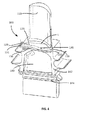
- the method 10 further comprises adding a new material 135 (illustrated in FIG. 4 ) in step 12 to the slash face 130 to build a new outer edge 136 (illustrated in FIG. 4 ).
- the new outer edge 136 replaces at least the removed portion 134 (illustrated in FIG. 3 ) that was formed during the removal process in step 11.
- the new outer edge 136 thereby extends the entire length L of the slash face 130 -- i.e., from the leading side 131 to the trailing side 139 of the bucket platform 120.
- the new material 135 may be added to the slash face 130 at the removed portion 134 via any suitable method given the type of material utilized.
- the new material 135 may be added in step 12 via laser cladding.
- other material addition methods may additionally or alternatively be used such as welding, brazing or the like.
- the new material 135 added in step 12 is added to build the new outer edge 136 of the slash face 130.
- the new material 135 added to the slash face 130 may exceed the dimensions of the new outer edge 136 such that it can be machined down to its final dimensions as will become appreciated herein. In even some embodiments, these final dimensions will exceed the original dimensions of the original outer edge 132 (illustrated in FIG. 2 ) as will also become appreciated herein.
- the new material 135 added in step 12 may comprise any suitable material for the utilization of the turbine bucket 100.
- the new material 135 may comprise the same type of material that was removed from the turbine bucket 100 in step 11.
- the new material 135 may comprise a different material than the original material of the original outer edge 132.
- the new material 135 may be more resistant to oxidation than the original material of the original outer edge 132.
- the new outer edge 136 may thereby possess increased oxidation resistance compared to the original, pre-modified turbine bucket 100.
- the method 10 may optionally further include machining the new material 135 after it is added to form the new outer edge 136 in step 13. Machining in step 13 may include any applicable process that shapes the added new material 135 to its final dimensions, finishes the surface of the new outer edge 136 to suitable characteristics, and/or otherwise treats the new material 135 prior to utilization of the turbine bucket 100.
- step 12 after new material 135 is added in step 12, some of the new material 135 may be machined via milling, grinding or the like and may be automated, manual or combinations thereof. Machining in step 13 may also occur via one single pass or through multiple iterations. Machining may continue in step 13 to bring the dimensions of the new outer edge 136 within a specified tolerance for the modified turbine bucket 100.
- the new outer edge 136 is machined back to the same dimensional tolerance of the original outer edge 132.
- the dimensional tolerance of the original outer edge 132 can refer to the dimensional tolerance of the outer edge as originally designed and/or manufactured by an original equipment manufacturer, or the outer edge as originally received by a facility that may have undergone one or more previous modifications (e.g., repairs, adjustments, upgrades, etc.) prior to undergoing the modification through method 10.
- one or more of the dimensions of the new outer edge 136 of the slash face 130 may be different than the original dimensions of the original outer edge 132 (i.e., different than the original design/manufacturing or different than the turbine bucket 100 as it existed prior to undergoing method 10).
- one or more of the dimensions of the new outer edge 136 may be greater than the original outer edge 132.
- the new outer edge 136 may extend further from the turbine bucket 100 than the original outer edge 132 for any suitable distance such that it would not interfere with the slash face of an adjacent turbine bucket.
- the new outer edge 136 may extend for a distance of about 1.270 mm making it extend about 0.254 mm further out than the original outer edge 132.
- Such embodiments can decrease the gap present between the two slash faces 130 of adjacent turbine buckets 100 once installed on a turbine wheel. This, in turn, can reduce hot gas ingestion and may allow for increased performance.
- the turbine bucket 100 may have both slash faces 130 modified via method 10 - i.e., modifying the slash face 130 on the pressure side as well as the slash face 130 on the suction side of the turbine bucket 100.
- each slash face may undergo the same steps at the same time, may undergo the method 10 independently, or any variation thereof.
- the new outer edges 136 of each slash face 130 may be sized to the same dimensions or to different dimensions, each of which may or may not be the same as the original dimensions of the original outer edges 132.
- turbine buckets may be modified by removing the entire length of an original outer edge of a slash face, adding new material and potentially machining the new material to produce a new outer edge of the slash face.
- the turbine bucket can have more uniform properties across its entire slash face.
- the new outer edge may possess stronger oxidation properties and/or greater dimensions than the original outer edge of the slash face to promote a stronger, longer lasting new outer edge with a smaller gap between adjacent turbine buckets.
Landscapes
- Engineering & Computer Science (AREA)
- Mechanical Engineering (AREA)
- General Engineering & Computer Science (AREA)
- Turbine Rotor Nozzle Sealing (AREA)
Abstract
Description
- The subject matter disclosed herein relates to modifying turbine buckets and, more specifically, to modifying slash faces of turbine buckets.
- Turbine buckets for industrial applications can experience extended service cycles in hostile conditions that may include operating temperatures exceeding 1400°C. High temperature performance alloys (such as nickel and cobalt super alloys) may be utilized to extend service life of these turbine components. However, even these high performance alloys may be subject to erosion, oxidation or other distress. Turbine buckets may therefore undergo modification to provide for continued operation (e.g., through repair, adjustment, upgrades, etc.). For example, slash faces on bucket platforms may undergo modification to potentially remedy areas of oxidation or erosion. However, the modification of such high temperature performance alloys may be difficult, particularly when only addressing localized areas.
- Accordingly, alternative modified turbine buckets and methods for modifying turbine buckets would be welcome in the art.
- In one embodiment, a method for modifying a turbine bucket is disclosed. The method includes removing at least an original outer edge for an entire length of the slash face of the turbine bucket. The method further includes adding a new material to the slash face to build a new outer edge, wherein the new outer edge extends the entire length of the slash face.
- In another embodiment, a modified turbine bucket is disclosed. The modified turbine bucket includes an airfoil extending from a bucket platform and a root portion extending from an opposite side of the bucket platform. The modified turbine bucket further includes a slash face on the bucket platform, the slash face including a new outer edge, wherein the original outer edge was removed for an entire length of the slash face of the turbine bucket prior to adding new material to the slash face to build the new outer edge, and wherein the new outer edge extends the entire length of the slash face.
- These and additional features provided by the embodiments discussed herein will be more fully understood in view of the following detailed description, in conjunction with the drawings.
- The embodiments set forth in the drawings are illustrative and exemplary in nature and not intended to limit the inventions defined by the claims. The following detailed description of the illustrative embodiments can be understood when read in conjunction with the following drawings, where like structure is indicated with like reference numerals and in which:
-
FIG. 1 is a method for modifying a turbine bucket according to one or more embodiments shown or described herein; -
FIG. 2 is a perspective view of a turbine bucket with an original slash face according to one or more embodiments shown or described herein; -
FIG. 3 is a perspective view of a turbine bucket with a partially removed slash face according to one or more embodiments shown or described herein; and, -
FIG. 4 is a perspective view of a turbine bucket with a modified slash face according to one or more embodiments shown or described herein. - One or more specific embodiments of the present invention will be described below. In an effort to provide a concise description of these embodiments, all features of an actual implementation may not be described in the specification. It should be appreciated that in the development of any such actual implementation, as in any engineering or design project, numerous implementation-specific decisions must be made to achieve the developers' specific goals, such as compliance with system-related and business-related constraints, which may vary from one implementation to another. Moreover, it should be appreciated that such a development effort might be complex and time consuming, but would nevertheless be a routine undertaking of design, fabrication, and manufacture for those of ordinary skill having the benefit of this disclosure.
- When introducing elements of various embodiments of the present invention, the articles "a," "an," "the," and "said" are intended to mean that there are one or more of the elements. The terms "comprising," "including," and "having" are intended to be inclusive and mean that there may be additional elements other than the listed elements.
- Methods for modifying slash faces of turbine buckets disclosed herein generally comprise removing an original outer edge for an entire length of the slash face and adding a new material to build a new outer edge that extends the entire length of the slash face. Modifying the entire length of the slash face can promote uniform properties across the entire new outer edge. The new material may also provide greater oxidation resistance or other durability related qualities compared to the original outer edge, or, even be built to greater dimensions to reduce the gap between slash faces of adjacent turbine buckets. The methods and modified turbine buckets will now be discussed in more detail herein.
- Referring to
FIGS. 1-4 , amethod 10 is illustrated for modifying aturbine bucket 100, and, more specifically, modifying aslash face 130 of theturbine bucket 100. As best illustrated inFIG. 2 , aturbine bucket 100 generally comprises anairfoil 110 extending from abucket platform 120 and aroot portion 140, including ashank 142 and adovetail 144, extending from an opposite side of the bucket platform. It should be appreciated that theturbine bucket 100, when placed in a turbine wheel (not illustrated) is one of an annular array of turbine buckets secured about the periphery of the turbine wheel. While axial entry buckets are disclosed herein, it should also be appreciated that the embodiments hereof may also be applied to tangential entry buckets. Furthermore, whileFIGS. 2-4 illustrate turbine buckets 100 at various stages of themethod 10, it should be appreciated that these illustrations are exemplary only andother turbine buckets 100 embodying additional or alternative features may also be realized. - Still referring to
FIG. 2 , thebucket platform 120 of theturbine bucket 100 comprises aslash face 130 on each side of theairfoil 110. Theslash face 130 extends the entire length L of thebucket platform 120 from the leadingside 131 to thetrailing side 139. When installed on a turbine wheel, theslash face 130 of theturbine bucket 100 will circumferentially oppose an adjacent slash face of an adjacent turbine bucket (not illustrated) to form a gap there between. In some embodiments, eachslash face 130 may additionally comprise agroove 133 for receiving a damper pin (not illustrated) to operate as a vibration damper. - The
turbine bucket 100 can comprise any suitable material or materials such as high temperature performance alloys (e.g., nickel and cobalt based super alloys). Furthermore, theturbine bucket 100 can comprise any stage turbine bucket for any frame turbine. In some specific embodiments, theturbine bucket 100 may comprise a first stage turbine bucket that experiences higher operating temperatures than subsequent stage turbine buckets. - Referring now to
FIGS. 1-3 , themethod 10 is illustrated for modifying theturbine bucket 100, and, more specifically, modifying theslash face 130 of theturbine bucket 100. Themethod 10 first comprises removing at least an originalouter edge 132 for an entire length L of theslash face 130 of theturbine bucket 100 instep 11. - The original outer edge 132 (illustrated in
FIG. 2 ) of theslash face 130 comprises the outer portion of material that forms a gap with the slash face of an adjacent turbine bucket (not illustrated) when installed on a turbine wheel. As used herein "original outer edge" can refer to the outer edge as originally designed and/or manufactured by an original equipment manufacturer, or the outer edge as originally received by a facility that may have undergone one or more previous modifications (e.g., repairs, adjustments, upgrades, etc.) prior to undergoing the modification throughmethod 10. The originalouter edge 132 is removed for the entire length L of theslash face 130, i.e., from the leadingside 131 to thetrailing side 139 of thebucket platform 120 to form a removed portion 134 (illustrated inFIG. 3 ). By removing the entire length L of theoriginal edge 132, the newouter edge 136 can potentially have more uniform properties than if just a portion of the originalouter edge 132 were removed (particularly if thenew material 135 is different than the original material as will become appreciated herein). Removal may occur through any suitable tools, methods or combinations thereof. For example, in some embodiments removal instep 11 may occur via milling, grinding or the like and may be automated, manual or combinations thereof. Removal instep 11 may also occur via one single pass or through multiple iterations. - The original
outer edge 132 may be removed for any suitable depth. For example, when theslash face 130 comprises erosion or other wear present from sustained operation, theouter edge 132 may be removed for a suitable depth that allows for the complete removal of any such targeted material. In some embodiments, the originalouter edge 132 of theslash face 130 is removed at a removal depth of about 1.270 mm to about 1.016 mm. In some embodiments, the removal depth may be uniform across the entire length L of theslash face 130. In other embodiments, the removal depth may vary with respect to different locations across the length L of theslash face 130. - Referring now to
FIGS. 1 and3-4 , themethod 10 further comprises adding a new material 135 (illustrated inFIG. 4 ) instep 12 to theslash face 130 to build a new outer edge 136 (illustrated inFIG. 4 ). The newouter edge 136 replaces at least the removed portion 134 (illustrated inFIG. 3 ) that was formed during the removal process instep 11. The newouter edge 136 thereby extends the entire length L of theslash face 130 -- i.e., from the leadingside 131 to thetrailing side 139 of thebucket platform 120. - The
new material 135 may be added to theslash face 130 at the removedportion 134 via any suitable method given the type of material utilized. For example, in some embodiments thenew material 135 may be added instep 12 via laser cladding. In some embodiments, other material addition methods may additionally or alternatively be used such as welding, brazing or the like. - The
new material 135 added instep 12 is added to build the newouter edge 136 of theslash face 130. In some embodiments, thenew material 135 added to theslash face 130 may exceed the dimensions of the newouter edge 136 such that it can be machined down to its final dimensions as will become appreciated herein. In even some embodiments, these final dimensions will exceed the original dimensions of the original outer edge 132 (illustrated inFIG. 2 ) as will also become appreciated herein. Thenew material 135 added instep 12 may comprise any suitable material for the utilization of theturbine bucket 100. For example, in some embodiments, thenew material 135 may comprise the same type of material that was removed from theturbine bucket 100 instep 11. However, in some embodiments, thenew material 135 may comprise a different material than the original material of the originalouter edge 132. For example, in some embodiments, thenew material 135 may be more resistant to oxidation than the original material of the originalouter edge 132. In such embodiments, the newouter edge 136 may thereby possess increased oxidation resistance compared to the original,pre-modified turbine bucket 100. - Referring to
FIGS. 1 and4 , themethod 10 may optionally further include machining thenew material 135 after it is added to form the newouter edge 136 instep 13. Machining instep 13 may include any applicable process that shapes the addednew material 135 to its final dimensions, finishes the surface of the newouter edge 136 to suitable characteristics, and/or otherwise treats thenew material 135 prior to utilization of theturbine bucket 100. - For example, in some embodiments, after
new material 135 is added instep 12, some of thenew material 135 may be machined via milling, grinding or the like and may be automated, manual or combinations thereof. Machining instep 13 may also occur via one single pass or through multiple iterations. Machining may continue instep 13 to bring the dimensions of the newouter edge 136 within a specified tolerance for the modifiedturbine bucket 100. - In some embodiments, the new
outer edge 136 is machined back to the same dimensional tolerance of the originalouter edge 132. As discussed above, the dimensional tolerance of the originalouter edge 132 can refer to the dimensional tolerance of the outer edge as originally designed and/or manufactured by an original equipment manufacturer, or the outer edge as originally received by a facility that may have undergone one or more previous modifications (e.g., repairs, adjustments, upgrades, etc.) prior to undergoing the modification throughmethod 10. - In other embodiments, one or more of the dimensions of the new
outer edge 136 of theslash face 130 may be different than the original dimensions of the original outer edge 132 (i.e., different than the original design/manufacturing or different than theturbine bucket 100 as it existed prior to undergoing method 10). For example, in some embodiments one or more of the dimensions of the newouter edge 136 may be greater than the originalouter edge 132. In such embodiments, for example, the newouter edge 136 may extend further from theturbine bucket 100 than the originalouter edge 132 for any suitable distance such that it would not interfere with the slash face of an adjacent turbine bucket. For instance, if the originalouter edge 132 was removed for a depth of about 1.016 mm, the newouter edge 136 may extend for a distance of about 1.270 mm making it extend about 0.254 mm further out than the originalouter edge 132. Such embodiments can decrease the gap present between the two slash faces 130 ofadjacent turbine buckets 100 once installed on a turbine wheel. This, in turn, can reduce hot gas ingestion and may allow for increased performance. - In even some embodiments, the
turbine bucket 100 may have both slash faces 130 modified via method 10 - i.e., modifying theslash face 130 on the pressure side as well as theslash face 130 on the suction side of theturbine bucket 100. In such embodiments, each slash face may undergo the same steps at the same time, may undergo themethod 10 independently, or any variation thereof. Furthermore, the newouter edges 136 of eachslash face 130 may be sized to the same dimensions or to different dimensions, each of which may or may not be the same as the original dimensions of the originalouter edges 132. - It should now be appreciated that turbine buckets may be modified by removing the entire length of an original outer edge of a slash face, adding new material and potentially machining the new material to produce a new outer edge of the slash face. By modifying the entire length of the slash face, the turbine bucket can have more uniform properties across its entire slash face. Furthermore, the new outer edge may possess stronger oxidation properties and/or greater dimensions than the original outer edge of the slash face to promote a stronger, longer lasting new outer edge with a smaller gap between adjacent turbine buckets.
- While the invention has been described in detail in connection with only a limited number of embodiments, it should be readily understood that the invention is not limited to such disclosed embodiments. Rather, the invention can be modified to incorporate any number of variations, alterations, substitutions or equivalent arrangements not heretofore described, but which are commensurate with the spirit and scope of the invention. Additionally, while various embodiments of the invention have been described, it is to be understood that aspects of the invention may include only some of the described embodiments. Accordingly, the invention is not to be seen as limited by the foregoing description, but is only limited by the scope of the appended claims.
- Various aspects and embodiments of the present invention are defined by the following numbered clauses:
- 1. A method for modifying a turbine bucket, the method comprising:
- removing at least an original outer edge for an entire length of a slash face of the turbine bucket; and,
- adding a new material to the slash face to build a new outer edge, wherein the new outer edge extends the entire length of the slash face.
- 2. The method of clause 1, further comprising machining the new material after it is added to form the new outer edge.
- 3. The method of any preceding clause, wherein the new outer edge extends further from the turbine bucket than the original outer edge.
- 4. The method of any preceding clause, wherein the new material comprises a different material than an original material of the original outer edge.
- 5. The method of any preceding clause, wherein the new material is more resistant to oxidation than the original material of the original outer edge.
- 6. The method of any preceding clause, wherein removing at least the original outer edge for the entire length of the slash face is performed at a removal depth of about 1.270 mm to about 1.016 mm.
- 7. The method of any preceding clause, wherein the new material is added via laser cladding.
- 8. The method of any preceding clause, further comprising:
- removing at least a second original outer edge for the entire length of a second slash face of the turbine bucket; and,
- adding the new material to the second slash face to build a second new outer edge, wherein the second new outer edge extends the entire length of the second slash face.
- 9. The method of any preceding clause, further comprising machining the new material after it is added to form the second new outer edge.
- 10. The method of any preceding clause, wherein the second new outer edge extends further from the turbine bucket than the second original outer edge.
- 11. A modified turbine bucket comprising:
- an airfoil extending from a bucket platform;
- a root portion extending from an opposite side of the bucket platform; and,
- a slash face on the bucket platform, the slash face comprising a new outer edge;
wherein an original outer edge was removed for an entire length of the slash face of the turbine bucket prior to adding new material to the slash face to build the new outer edge; and,
wherein the new outer edge extends the entire length of the slash face.
- 12. The modified turbine bucket of any preceding clause, wherein the new material was machined after being added to form the new outer edge.
- 13. The modified turbine bucket of any preceding clause, wherein the new outer edge extends further from the turbine bucket than the original outer edge.
- 14. The modified turbine bucket of any preceding clause, wherein the new material comprises a different material than the original material of the original outer edge.
- 15. The modified turbine bucket of any preceding clause, wherein the new material is more resistant to oxidation than the original material of the original outer edge.
- 16. The modified turbine bucket of any preceding clause, wherein the original outer edge was removed at a removal depth of about 1.270 mm to about 1.016 mm.
- 17. The modified turbine bucket of
claim 11 further comprising:- a second slash face comprising a second new outer edge;
- wherein a second original outer edge was removed for the entire length of the second slash face of the turbine bucket prior to adding new material to the second slash face to build the second new outer edge; and,
- wherein the second new outer edge extends the entire length of the second slash face.
- 18. The modified turbine bucket of any preceding clause, wherein the new material was machined after being added to the second slash face to form the second new outer edge.
- 19. The modified turbine bucket of any preceding clause, wherein the second new outer edge extends further from the turbine bucket than the second original outer edge.
- 20. The modified turbine bucket of any preceding clause, wherein the modified turbine bucket comprises a first stage bucket.
Claims (15)
- A method (10) for modifying a turbine bucket, the method comprising:removing (11) at least an original outer edge for an entire length of a slash face of the turbine bucket; and,adding (12) a new material to the slash face to build a new outer edge, wherein the new outer edge extends the entire length of the slash face.
- The method of claim 1 further comprising machining (13) the new material after it is added to form the new outer edge, wherein, preferably, the new outer edge extends further from the turbine bucket than the original outer edge
- The method of claim 1 or claim 2, wherein the new material comprises a different material than an original material of the original outer edge, wherein, preferably, the new material is more resistant to oxidation than the original material of the original outer edge.
- The method of claim 1, 2 or 3, wherein removing (11) at least the original outer edge for the entire length of the slash face is performed at a removal depth of about 1.270 mm to about 1.016 mm.
- The method of any preceding claim, wherein the new material is added via laser cladding.
- The method of any preceding claim, further comprising:removing at least a second original outer edge for the entire length of a second slash face of the turbine bucket; and,adding the new material to the second slash face to build a second new outer edge, wherein the second new outer edge extends the entire length of the second slash face.
- The method of claim 8, further comprising machining the new material after it is added to form the second new outer edge, wherein, preferably, the second new outer edge extends further from the turbine bucket than the second original outer edge.
- A modified turbine bucket (100) comprising:an airfoil (110) extending from a bucket platform (120);a root portion (140) extending from an opposite side of the bucket platform (120); and,a slash face (130) on the bucket platform (120), the slash face (130) comprising a new outer edge;
wherein an original outer edge (132) was removed for an entire length of the slash face (130) of the turbine bucket (100) prior to adding new material to the slash face (130) to build the new outer edge; and,
wherein the new outer edge extends the entire length of the slash face (130). - The modified turbine bucket of claim 8, wherein the new material was machined after being added to form the new outer edge, wherein, preferably, the new outer edge extends further from the turbine bucket than the original outer edge (132).
- The modified turbine bucket of claim 8 or claim 9, wherein the new material comprises a different material than the original material of the original outer edge (132), wherein, preferably, the new material is more resistant to oxidation than the original material of the original outer edge (132).
- The modified turbine bucket of claim 8, 9 or 10, wherein the original outer edge (132) was removed at a removal depth of about 1.270 mm to about 1.016 mm.
- The modified turbine bucket of any one of claims 8 to 11, further comprising:a second slash face comprising a second new outer edge;wherein a second original outer edge was removed for the entire length of the second slash face of the turbine bucket prior to adding new material to the second slash face to build the second new outer edge; and,wherein the second new outer edge extends the entire length of the second slash face.
- The modified turbine bucket of claim 12, wherein the new material was machined after being added to the second slash face to form the second new outer edge.
- The modified turbine bucket of claim 12 or claim 13, wherein the second new outer edge extends further from the turbine bucket (100) than the second original outer edge.
- The modified turbine bucket of any one of claims 8 to 14, wherein the modified turbine bucket (100) comprises a first stage bucket.
Applications Claiming Priority (1)
| Application Number | Priority Date | Filing Date | Title |
|---|---|---|---|
| US13/894,514 US20140341743A1 (en) | 2013-05-15 | 2013-05-15 | Modified turbine buckets and methods for modifying turbine buckets |
Publications (1)
| Publication Number | Publication Date |
|---|---|
| EP2803819A1 true EP2803819A1 (en) | 2014-11-19 |
Family
ID=50771052
Family Applications (1)
| Application Number | Title | Priority Date | Filing Date |
|---|---|---|---|
| EP14168028.0A Withdrawn EP2803819A1 (en) | 2013-05-15 | 2014-05-13 | Modified turbine buckets and methods for modifying turbine buckets |
Country Status (4)
| Country | Link |
|---|---|
| US (1) | US20140341743A1 (en) |
| EP (1) | EP2803819A1 (en) |
| JP (1) | JP2014224533A (en) |
| CN (1) | CN104165069A (en) |
Families Citing this family (3)
| Publication number | Priority date | Publication date | Assignee | Title |
|---|---|---|---|---|
| JP2017020421A (en) * | 2015-07-10 | 2017-01-26 | 株式会社東芝 | Method of repairing turbine component, and turbine component |
| US10174617B2 (en) | 2015-12-10 | 2019-01-08 | General Electric Company | Systems and methods for deep tip crack repair |
| CN105627969B (en) * | 2015-12-29 | 2018-04-13 | 中国航空工业集团公司沈阳发动机设计研究所 | A correction method for engine high-pressure turbine clearance value |
Citations (5)
| Publication number | Priority date | Publication date | Assignee | Title |
|---|---|---|---|---|
| US20060090336A1 (en) * | 2004-10-29 | 2006-05-04 | Graham James H | Adaptive machining and weld repair process |
| WO2006094935A1 (en) * | 2005-03-05 | 2006-09-14 | Alstom Technology Ltd | Turbine blades and methods for depositing an erosion resistant coating on the same |
| WO2011035772A1 (en) * | 2009-09-26 | 2011-03-31 | Mtu Aero Engines Gmbh | Method for repairing an integral rotor and integral rotor |
| EP2524759A1 (en) * | 2011-05-16 | 2012-11-21 | General Electric Company | Method of hardfacing a portion of a bucket using cold metal transfer; corresponding turbine bucket |
| US20130042474A1 (en) * | 2011-08-17 | 2013-02-21 | General Electric Company | Rotor seal wire groove repair |
Family Cites Families (2)
| Publication number | Priority date | Publication date | Assignee | Title |
|---|---|---|---|---|
| US20050172485A1 (en) * | 2004-02-10 | 2005-08-11 | Ramsay Mussen | Method of repair for cast article |
| US7587818B2 (en) * | 2004-12-23 | 2009-09-15 | General Electric Company | Repair of gas turbine blade tip without recoating the repaired blade tip |
-
2013
- 2013-05-15 US US13/894,514 patent/US20140341743A1/en not_active Abandoned
-
2014
- 2014-05-09 JP JP2014097261A patent/JP2014224533A/en active Pending
- 2014-05-13 EP EP14168028.0A patent/EP2803819A1/en not_active Withdrawn
- 2014-05-15 CN CN201410270290.1A patent/CN104165069A/en active Pending
Patent Citations (5)
| Publication number | Priority date | Publication date | Assignee | Title |
|---|---|---|---|---|
| US20060090336A1 (en) * | 2004-10-29 | 2006-05-04 | Graham James H | Adaptive machining and weld repair process |
| WO2006094935A1 (en) * | 2005-03-05 | 2006-09-14 | Alstom Technology Ltd | Turbine blades and methods for depositing an erosion resistant coating on the same |
| WO2011035772A1 (en) * | 2009-09-26 | 2011-03-31 | Mtu Aero Engines Gmbh | Method for repairing an integral rotor and integral rotor |
| EP2524759A1 (en) * | 2011-05-16 | 2012-11-21 | General Electric Company | Method of hardfacing a portion of a bucket using cold metal transfer; corresponding turbine bucket |
| US20130042474A1 (en) * | 2011-08-17 | 2013-02-21 | General Electric Company | Rotor seal wire groove repair |
Also Published As
| Publication number | Publication date |
|---|---|
| CN104165069A (en) | 2014-11-26 |
| US20140341743A1 (en) | 2014-11-20 |
| JP2014224533A (en) | 2014-12-04 |
Similar Documents
| Publication | Publication Date | Title |
|---|---|---|
| US8959738B2 (en) | Process of repairing a component, a repair tool for a component, and a component | |
| US7984547B2 (en) | Method for manufacturing and/or repairing components for gas turbines | |
| US20120198676A1 (en) | Method for repairing or reconditioning a badly damaged component, in particular from the hot gas region of a gas turbine | |
| US8689442B2 (en) | Method for the fabrication of integrally bladed rotors | |
| JP6302479B2 (en) | Device with engineering surface features and corresponding method for reducing wear and friction in CMC-metal attachments | |
| US10005144B2 (en) | Broach tool rake face with a tailored surface topography | |
| US10001017B2 (en) | Turbomachine component with a stress relief cavity | |
| US8151459B2 (en) | Forming firtree profiles | |
| EP2998060B1 (en) | Method of replacing damaged blade | |
| EP2803819A1 (en) | Modified turbine buckets and methods for modifying turbine buckets | |
| CN101169049A (en) | Blade/disk mortise cuts for blade/disc stress reduction | |
| US20120022678A1 (en) | Linear friction welding of an aerofoil blisk | |
| US20160146014A1 (en) | Modified bucket platforms of turbine buckets and methods for modifying bucket platforms of turbine buckets | |
| CN114340818B (en) | Combined additive and subtractive manufacturing of bladed rotors | |
| EP3124754A1 (en) | Near flow path seal for a turbomachine | |
| US20160024925A1 (en) | Turbine Disk Fatigue Rejuvenation | |
| WO2020032964A1 (en) | Friction stir additive manufacturing and repair of turbine components | |
| KR101114535B1 (en) | Grinding method for bucket tip of the turbine-rotor | |
| CN107687445B (en) | Impeller assembly, method of modifying an impeller and method of mounting blades to an impeller | |
| US10989061B2 (en) | Tip machining method and system | |
| US11492909B2 (en) | Platform seal and damper assembly for turbomachinery and methodology for forming said assembly |
Legal Events
| Date | Code | Title | Description |
|---|---|---|---|
| PUAI | Public reference made under article 153(3) epc to a published international application that has entered the european phase |
Free format text: ORIGINAL CODE: 0009012 |
|
| 17P | Request for examination filed |
Effective date: 20140513 |
|
| AK | Designated contracting states |
Kind code of ref document: A1 Designated state(s): AL AT BE BG CH CY CZ DE DK EE ES FI FR GB GR HR HU IE IS IT LI LT LU LV MC MK MT NL NO PL PT RO RS SE SI SK SM TR |
|
| AX | Request for extension of the european patent |
Extension state: BA ME |
|
| R17P | Request for examination filed (corrected) |
Effective date: 20150519 |
|
| RBV | Designated contracting states (corrected) |
Designated state(s): AL AT BE BG CH CY CZ DE DK EE ES FI FR GB GR HR HU IE IS IT LI LT LU LV MC MK MT NL NO PL PT RO RS SE SI SK SM TR |
|
| STAA | Information on the status of an ep patent application or granted ep patent |
Free format text: STATUS: THE APPLICATION IS DEEMED TO BE WITHDRAWN |
|
| 18D | Application deemed to be withdrawn |
Effective date: 20171201 |