EP2803311A1 - Dishwasher with integrated lighting - Google Patents
Dishwasher with integrated lighting Download PDFInfo
- Publication number
- EP2803311A1 EP2803311A1 EP14164066.4A EP14164066A EP2803311A1 EP 2803311 A1 EP2803311 A1 EP 2803311A1 EP 14164066 A EP14164066 A EP 14164066A EP 2803311 A1 EP2803311 A1 EP 2803311A1
- Authority
- EP
- European Patent Office
- Prior art keywords
- light source
- dish
- dishwasher
- tub
- dish holder
- Prior art date
- Legal status (The legal status is an assumption and is not a legal conclusion. Google has not performed a legal analysis and makes no representation as to the accuracy of the status listed.)
- Granted
Links
Images




Classifications
-
- A—HUMAN NECESSITIES
- A47—FURNITURE; DOMESTIC ARTICLES OR APPLIANCES; COFFEE MILLS; SPICE MILLS; SUCTION CLEANERS IN GENERAL
- A47L—DOMESTIC WASHING OR CLEANING; SUCTION CLEANERS IN GENERAL
- A47L15/00—Washing or rinsing machines for crockery or tableware
- A47L15/42—Details
- A47L15/50—Racks ; Baskets
-
- A—HUMAN NECESSITIES
- A47—FURNITURE; DOMESTIC ARTICLES OR APPLIANCES; COFFEE MILLS; SPICE MILLS; SUCTION CLEANERS IN GENERAL
- A47L—DOMESTIC WASHING OR CLEANING; SUCTION CLEANERS IN GENERAL
- A47L15/00—Washing or rinsing machines for crockery or tableware
- A47L15/42—Details
- A47L15/4246—Details of the tub
-
- A—HUMAN NECESSITIES
- A47—FURNITURE; DOMESTIC ARTICLES OR APPLIANCES; COFFEE MILLS; SPICE MILLS; SUCTION CLEANERS IN GENERAL
- A47L—DOMESTIC WASHING OR CLEANING; SUCTION CLEANERS IN GENERAL
- A47L15/00—Washing or rinsing machines for crockery or tableware
- A47L15/42—Details
- A47L15/4251—Details of the casing
- A47L15/4257—Details of the loading door
-
- A—HUMAN NECESSITIES
- A47—FURNITURE; DOMESTIC ARTICLES OR APPLIANCES; COFFEE MILLS; SPICE MILLS; SUCTION CLEANERS IN GENERAL
- A47L—DOMESTIC WASHING OR CLEANING; SUCTION CLEANERS IN GENERAL
- A47L15/00—Washing or rinsing machines for crockery or tableware
- A47L15/42—Details
- A47L15/4251—Details of the casing
- A47L15/4274—Arrangement of electrical components, e.g. control units or cables
-
- A—HUMAN NECESSITIES
- A47—FURNITURE; DOMESTIC ARTICLES OR APPLIANCES; COFFEE MILLS; SPICE MILLS; SUCTION CLEANERS IN GENERAL
- A47L—DOMESTIC WASHING OR CLEANING; SUCTION CLEANERS IN GENERAL
- A47L15/00—Washing or rinsing machines for crockery or tableware
- A47L15/42—Details
- A47L15/50—Racks ; Baskets
- A47L15/502—Cutlery baskets
Definitions
- Automatic dishwashers may include a plurality of components that are collectively controlled by a controller to treat dishes within a treating chamber according to an automatic cycle of operation.
- Such dishwashers may include illumination systems for illuminating the interior of the tub.
- the invention relates to a dishwasher for treating dishes according to an automatic cycle of operation.
- the dishwasher includes a tub at least partially defining a treating chamber for receiving dishes for treatment according to the cycle of operation and having an open face providing access to the treating chamber, a dish holder slidable relative to the tub through the open face between a loading position and a treating position, a light source provided on the dish holder for illuminating dishes contained in the dish holder, and a power source coupled to the light source by an electrical conductor wherein the electrical conductor is provided with slack to enable the dish holder to move at least partially out of the treating chamber.
- the light source may be oriented on the dish holder such that light emitted by the light source is initially directed away from a bottom of the tub.
- the power source may be located exteriorly of the tub.
- the electrical conductor may pass through a portion of the tub.
- the dish holder may comprise a drawer having a pan and the light source be provided on the pan.
- the light source may be oriented relative to the pan to initially upwardly direct at least a portion of the light emitted by the light source.
- the dish holder may comprise a dish rack and the light source be provided on the dish rack.
- the dish rack may comprise upper and lower dish racks and each of the upper and lower dish racks have a corresponding light source provided thereon for illuminating dishes contained in each of the of the upper and lower dish racks, respectively.
- the light sources may be operably coupled to a single power source by separate electrical conductors that are provided with slack to enable the upper and lower dish racks to move at least partially out of the treating chamber.
- the dishwasher includes a tub at least partially defining a treating chamber for receiving dishes for treatment according to the cycle of operation and having an open face providing access to the treating chamber, a dish holder slidable relative to the tub through the open face between a loading position and a treating position, a rail system slidably coupling the dish holder to the tub for movement relative to the treating chamber, a light source provided on the dish holder for illuminating dishes contained in the dish holder, and a power source selectively coupled to the light source by a contact connection provided on the rail system where the contact connection is closed to couple the power source to the light source when the dish holder is slid at least partially out of the treating chamber.
- the contact connection may comprise a rail of the rail system and a roller of the rail system.
- the light source may be operably coupled to the roller of the rail system and the power source be operably coupled to the rail of the rail system.
- the contact connection may comprise a spring finger that extends from the dish holder and is operably coupled with the light source. The spring finger may be in contact with a portion of the contact connection provided on the rail system when the dish holder is in the loading position.
- the dish holder may comprise a dish rack and the light source be provided on the dish rack.
- the dish rack may comprise upper and lower dish racks and each of the upper and lower dish racks have a corresponding light source provided thereon for illuminating dishes contained in each of the of the upper and lower dish racks, respectively.
- the light sources may be operably coupled to multiple power sources by contact connections provided on the rail system for the upper and lower dish racks. The light source may be directed away from a bottom of the tub.
- the dishwasher includes a tub at least partially defining a treating chamber for receiving dishes for treatment according to the cycle of operation and having an open face providing access to the treating chamber, a dish holder slidable relative to the tub through the open face between a loading position and a treating position, and a light pipe integrally formed with the dish holder for illuminating dishes contained in the dish holder.
- the dish holder may comprise a dish rack.
- the light pipe may be integrally formed with the dish rack.
- the dish rack may comprise a wire frame having multiple wire elements, and the light pipe forms one of the wire elements.
- the dish rack may have four sides, each comprising multiple wire elements, and wherein the light pipe forms at least a portion of a topmost wire element of at least one of the four sides.
- the dish rack may have four sides, and the light pipe extend along at least two of the four sides.
- the light pipe may extend along at least three of the four sides.
- the four sides of the dish rack may comprise a front side and a rear side joined by two lateral sides, and the light pipe extends along the rear and lateral sides.
- the dishwasher may further comprise a power source operably coupled with the light pipe.
- the dishwasher includes a tub at least partially defining a treating chamber for receiving dishes for treatment according to the cycle of operation and having an open face providing access to the treating chamber, a dish holder comprising a drawer slidable relative to the tub through the open face between a loading position and a treating position, and having an outer wall and an inner wall spaced from the outer wall to define a cavity, and a light source provided within the cavity for illuminating dishes contained in the dish holder.
- the light source may form a portion of the inner wall.
- the inner wall may comprise a transparent section, and the light source be provided behind the transparent section.
- the drawer may comprise a pan forming a portion of the bottom of the drawer, and may further comprise a second light source provided on the pan.
- the dishwasher may further comprise a power source operably coupled with the light source.
- the power source may be located exteriorly of the tub.
- the dishwasher includes a tub at least partially defining a treating chamber for receiving dishes for treatment according to the cycle of operation and having an open face providing access to the treating chamber, a molded dish holder slidable relative to the tub through the open face between a loading position and a treating position, and an insert-molded light source provided with the dish holder for illuminating dishes contained in the dish holder.
- the dish holder may comprise a drawer.
- the drawer may comprise an outer wall and an inner wall spaced from the outer wall to define a cavity, and the light source be molded to fit in the cavity.
- the dishwasher may further comprise a power source operably coupled with the light source.
- the power source may be located exteriorly of the tub.
- an automatic dishwasher 10 having a cabinet 12 defining an interior is illustrated.
- the cabinet 12 may be a chassis/frame with or without panels attached, respectively.
- the dishwasher 10 shares many features of a conventional automatic dishwasher, which will not be described in detail herein except as necessary for a complete understanding of the invention. While the present invention is described in terms of a conventional dishwashing unit, it could also be implemented in other types of dishwashing units, such as in-sink dishwashers, multi-tub dishwashers, or drawer-type dishwashers.
- a controller 14 may be located within the cabinet 12 and may be operably coupled with various components of the dishwasher 10 to implement one or more cycles of operation.
- a control panel or user interface 16 may be provided on the dishwasher 10 and coupled with the controller 14.
- the user interface 16 may include operational controls such as dials, lights, switches, and displays enabling a user to input commands, such as a cycle of operation, to the controller 14 and receive information.
- a tub 18 is located within the cabinet 12 and at least partially defines a treating chamber 20 with an access opening in the form of an open face.
- a cover illustrated as a door 22, may be hingedly mounted to the cabinet 12 and may move between a closed position, as shown in Figure 1 , wherein the door 22 covers or closes the open face of the treating chamber 20 and an opened position ( Figure 3 ), wherein the user may access the treating chamber 20.
- Dish holders have been illustrated in the form of upper and lower racks 24, 26.
- the upper and lower racks 24, 26 may be located within the treating chamber 20 and receive dishes for being treated.
- the upper and lower racks 24, 26 are mounted for slidable movement in and out of the treating chamber 20 for ease of loading and unloading.
- the upper and lower racks 24, 26 may be slidable relative to the tub 18 through the open face between a loading position and a treating position.
- the term "dish(es)" is intended to be generic to any item, single or plural, that may be treated in the dishwasher 10, including, without limitation; utensils, plates, pots, bowls, pans, glassware, and silverware. While not shown, additional utensil holders, such as a silverware basket on the interior of the door 22, may also be provided.
- a spraying system 28 may be provided for spraying liquid into the treating chamber 20 and is illustrated in the form of an upper sprayer 30, a mid-level rotatable sprayer 32, a lower rotatable spray arm 34, and a spray manifold 36.
- the upper sprayer 30 may be located above the upper rack 24 and is illustrated as a fixed spray nozzle that sprays liquid downwardly within the treating chamber 20.
- Mid-level rotatable sprayer 32 and lower rotatable spray arm 34 are located, respectively, beneath upper rack 24 and lower rack 26 and are illustrated as rotating spray arms.
- the mid-level spray arm 32 may provide a liquid spray upwardly through the bottom of the upper rack 24.
- the lower rotatable spray arm 34 may provide a liquid spray upwardly through the bottom of the lower rack 26.
- the mid-level rotatable sprayer 32 may optionally also provide a liquid spray downwardly onto the lower rack 26, but for purposes of simplification, this will not be illustrated herein.
- the spray manifold 36 may be fixedly mounted to the tub 18 adjacent to the lower rack 26 and may provide a liquid spray laterally through a side of the lower rack 26.
- the spray manifold 36 may not be limited to this position; rather, the spray manifold 36 may be located in virtually any part of the treating chamber 20.
- the spray manifold 36 may include multiple spray nozzles having apertures configured to spray wash liquid towards the lower rack 26.
- the spray nozzles may be fixed or rotatable with respect to the tub 18.
- a liquid recirculation system may be provided for recirculating liquid from the treating chamber 20 to the spraying system 28.
- the recirculation system may include a sump 38 and a pump assembly 40.
- the sump 38 collects the liquid sprayed in the treating chamber 20 and may be formed by a sloped or recessed portion of a bottom wall 42 of the tub 18.
- the pump assembly 40 may include both a drain pump 44 and a recirculation pump 46.
- the drain pump 44 may draw liquid from the sump 38 and pump the liquid out of the dishwasher 10 to a household drain line 48.
- the recirculation pump 46 may draw liquid from the sump 38 and pump the liquid to the spraying system 28 to supply liquid into the treating chamber 20.
- the pump assembly 40 may include a single pump configured to selectively supply wash liquid to either the spraying system 28 or the drain line 48, such as by configuring the pump to rotate in opposite directions, or by providing a suitable valve system.
- a liquid supply system may include a water supply conduit coupled with a household water supply for supplying water to the sump 38.
- the recirculation pump 46 has an outlet conduit 50 in fluid communication with the spraying system 28 for discharging wash liquid from the recirculation pump 46 to the sprayers 30-36.
- liquid may be supplied to the spray manifold 36, mid-level rotatable sprayer 32, and upper sprayer 30 through a supply tube 52 that extends generally rearward from the recirculation pump 46 and upwardly along a rear wall of the tub 18. While the supply tube 52 ultimately supplies liquid to the spray manifold 36, mid-level rotatable sprayer 32, and upper sprayer 30, it may fluidly communicate with one or more manifold tubes that directly transport liquid to the spray manifold 36, mid-level rotatable sprayer 32, and upper sprayer 30.
- diverters may be provided within the spraying system 28 such that liquid may be selectively supplied to each of the sprayers 30-36.
- the sprayers 30-36 spray water and/or treating chemistry onto the dish racks 24, 26 (and hence any dishes positioned thereon) to effect a recirculation of the liquid from the treating chamber 20 to the liquid spraying system 28 to define a recirculation flow path.
- a heating system having a heater 54 may be located within or near the sump 38 for heating liquid contained in the sump 38.
- a filtering system (not shown) may be fluidly coupled with the recirculation flow path for filtering the recirculated liquid.
- a light source 56 may be provided on one or both of the upper and lower racks 24, 26 for illuminating dishes contained therein.
- a light source 56 has been illustrated in the upper rack 24 only for clarity purposes.
- each of the upper and lower dish racks 24, 26 may have a corresponding light source provided thereon for illuminating dishes contained in each of the of the upper and lower dish racks 24, 26, respectively.
- the light source 56 may include a plurality of light sources including that the plurality of light sources may include light emitting diodes (LEDs).
- the light source 56 includes a first light source 58 and a second light source 60.
- the first and second light sources 58 and 60 may be operably coupled through a wired connection 59.
- Both of the first light source 58 and the second light source 60 have been illustrated as including several LEDs. It will be understood that the light source 56 may include any suitable light source and that any number of light sources may be provided on the upper rack 24 in any suitable location. Regardless of which of the upper and lower racks 24, 26 the light source(s) 56 are on, the light source(s) 56 may be oriented to initially upwardly direct at least a portion of the light emitted by the light source(s) 56. This may cause the dishes in the upper rack 24 and/or lower rack 26 to be illuminated while directing light away from the bottom of the tub 18, which may become dirty with use.
- a power source 62 may be coupled to the light source 56 by an electrical conductor such as a wire connection 64.
- the power source 62 has been illustrated as being located exteriorly of the tub 18 and the wire connection 64 has been illustrated as passing through the tub 18 and into the treating chamber 20, although the wire connection need not pass through the tub 18.
- the power source 62 may be located inside the tub 18. It is contemplated that the power source 62 may be a self-contained power source or that it may be wired or wirelessly connected to a main power source. For example, if the power source 62 is located within the tub 18 it may be inductively coupled to a power source located out of the tub 18. Alternatively, the power source 62 may be entirely self-contained. For example, if the power source 62 is located within the tub 18, it may include a battery pack, a flywheel, or a capacitor.
- the wire connection 64 may be provided with slack to enable the upper rack 24 to move at least partially out of the treating chamber 20, such as to the loading position.
- the light sources 56 may be operably coupled to a single power source 62 by separate wire connections, each provided with slack to enable the upper and lower dish racks 24, 26 to move at least partially out of the treating chamber 20.
- the light sources 56 may be operably coupled to multiple power sources 62 by slack wire connections 64.
- the controller 14 may be provided with a memory 66 and a central processing unit (CPU) 68.
- the memory 66 may be used for storing control software that may be executed by the CPU 68 in completing a cycle of operation using the dishwasher 10 and any additional software.
- the memory 66 may store one or more pre-programmed cycles of operation that may be selected by a user and completed by the dishwasher 10.
- a cycle of operation for the dishwasher 10 may include one or more of the following steps: a wash step, a rinse step, and a drying step.
- the wash step may further include a pre-wash step and a main wash step.
- the rinse step may also include multiple steps such as one or more additional rinsing steps performed in addition to a first rinsing.
- the amounts of water and/or rinse aid used during each of the multiple rinse steps may be varied.
- the drying step may have a non-heated drying step (so called "air only"), a heated drying step or a combination thereof. These multiple steps may also be performed by the dishwasher 10 in any desired combination.
- the controller 14 may be operably coupled with one or more components of the dishwasher 10 for communicating with and controlling the operation of the components to complete a cycle of operation.
- the controller 14 may be coupled with the recirculation pump 46 for circulation of liquid in the tub 18 and the drain pump 44 for drainage of liquid in the tub 18.
- the controller 14 may also be operably coupled to the heater 54 and one or more optional sensors 70.
- optional sensors 70 that may be communicably coupled with the controller 14 include a moisture sensor, a door sensor, a temperature sensor, a detergent and rinse aid presence/type sensor(s).
- the controller 14 may also be coupled to a dispenser 72, which may dispense a detergent during the wash step of the cycle of operation or a rinse aid during the rinse step of the cycle of operation.
- the controller 14 may be operably coupled with the power source 62 or the light source(s) 56 although this need not be the case.
- the door 22 is in a closed position, and the upper and lower racks 24, 26 are disposed within the treating chamber 20 in a use position, illustrated in Figure 1 , where they are exposed to washing fluid, such as water, and wash aids, such as detergents and rinse aids.
- washing fluid such as water
- wash aids such as detergents and rinse aids.
- the user may move the door 22 to an open position and may move the upper and lower racks 24, 26 from the treating chamber 20 to a load position where at least a portion of the racks 24, 26 resides exteriorly of the cabinet 12 and where the upper and lower racks 24, 26 may be emptied or filled.
- the load position is partially illustrated in Figure 3 , which shows the door 22 in the open position and the upper rack 24 in the load position; the lower rack 26 remains in the use position.
- the wire connection 64 becomes more taunt as the upper rack 24 is moved to the load position.
- the light sources 56 are illustrated as initially directing light towards dishes in the upper rack 24.
- Figure 4 illustrates a second embodiment of the dishwasher 110, with an alternative light source 156/power source 162 configuration.
- the second embodiment is similar to the first embodiment as illustrated in Figure 1 . Therefore, like parts will be identified with like numerals increased by 100, with it being understood that the description of the like parts of the first embodiment applies to the second embodiment, unless otherwise noted.
- the upper and lower racks 124, 126 are slidably mounted to the tub 118 by a rail system 180.
- the rail system 180 may include a pair of rails 182 formed on side walls of the tub 118 in alignment with the inner surface of the door 122 when the door 122 is in the open position such that the lower rack 126 may be moved out of the treating chamber 120 over the door 122.
- the lower rack 126 may be provided with wheels 184 which roll along the rails 182 and allow the lower rack 126 to be rolled out at least partially onto the inner face of the open door 122 and into the load position.
- the rail system 180 for the upper rack 124 may be slightly more complex and may include a set of rails 186 on which the upper rack 124 may be movably supported and which in turn may be movably supported on the side walls of the tub 118.
- the set of rails 186 may be positioned and capable of horizontal movement by support rollers (not shown) on the side wall of the tub 118.
- the upper rack 124 has on each side at least two projecting rollers 188 that operably couple with the set of rails 186 and allow the upper rack 124 to slide freely along the set of rails 186.
- the upper rack 124 may roll along the set of rails 186 as the set of rails186 rolls along the supporting rollers (not shown) so that the upper rack 124 may slide far enough with the set of rails 186 to move completely out of the treating chamber 120.
- the rail system 180 facilitates movement of the upper and lower racks 124, 126 along a path of travel between the use and load positions. While the rail system 180 permits the complete extension of the upper and lower racks 124, 126 beyond the tub 118, other rail systems may not. Any suitable rail system may be utilized and the rail system 180 described herein is merely for exemplary purposes. It has been contemplated that any other type of slides or rail system or any other mechanism suitable for slidably coupling the dish holders to the tub 118 and facilitating movement of the dish holders between the use and load positions may be utilized.
- At least one light source 156 is provided in the dishwasher 110.
- light sources 156 have been illustrated as being provided on each of the upper and lower racks 124, 126 for illuminating dishes contained in the upper and lower racks 124, 126, respectively.
- a power source 162 may be selectively coupled to the light source(s) 156 by a contact connection 181 ( Figure 5A and Figure 5B ) provided on the rail system 180.
- the contact connection 181 may be closed to couple the power source 162 to the light source 156 when the upper and lower racks 124, 126 are slid at least partially out of the treating chamber 120.
- the contact connection 181 includes at least a portion of the rail 186 of the rail system 180 and a roller 188 of the rail system 180.
- the light source 156 on the upper rack 124 may be operably coupled to the roller 188 of the rail system 180 such as through a connection 187.
- the power source 162 is operably coupled, directly, such as wired, or indirectly, such as wireless, including a capacitive coupling, to the rail 186 of the rail system 180.
- the power source 162 has been illustrated as being located exteriorly of the tub 118. Alternatively, the power source 162 may be located inside the tub 118. It is contemplated that the rail 186 may be directly or indirectly coupled, such as through induction, with the power source 162.
- the contact connection 181 may be formed and the light source 156 may be illuminated. So long as the roller 188 and the rail 186 are in contact the contact connection 181 may be closed to couple the power source 162 to the light source 156 including when the upper rack 124 is slid out of the treating chamber 120, as shown in Figure 5A .
- the rail 186 and the roller 188 may also be formed such that the contact connection 181 is only closed when the upper rack 124 is at least partially out of the treating chamber 120.
- a portion of the rail 186 may be insulated so that the contact connection 181 is not closed when the upper rack 124 is located inside the treating chamber 120. In such an instance a conductive portion 189 of the rail 186 would make a contact connection 181 with the roller 188 when the upper rack 124 is slid out of the treating chamber 120.
- the contact connection 181 includes a spring finger 190 that extends from the lower rack 126 and is operably coupled with the light source 156.
- the spring finger 190 of the contact connection 181 may be in contact with a portion of the contact connection 181 provided on the rail system 180, such as a portion 192 of the rail 182, when the lower rack 126 is in the loading position, as shown in Figure 5 . In this manner, the contact connection 181 is closed when the lower rack 126 is in the loading position.
- the light sources 156 may be operably coupled to multiple power sources 162 as illustrated or may be coupled to a single power source 162 by contact connections 181 provided on the rail system 180 for each of the upper and lower dish racks 124, 126.
- the light source(s) may be provided on the upper and lower racks in any suitable manner including that the light source(s) may be attached to the upper and lower racks or may be integrated with the upper and lower racks.
- the light source may be in the form of a light pipe that is integrated with the rack and forms a portion of one of the racks.
- Figure 6 illustrates that the light source is a light pipe 200 integrated in a dish rack 202. In the dish rack 202 a portion of the dish rack 202 could be formed from the light pipe 200 instead of one of the coated wire elements 206 forming the traditional wire frame rack.
- the light pipe 200 forms a portion of the topmost wire element of the wire frame rack.
- the dish rack 202 has four sides, including a front side 224 and a back side 226 joined by two lateral sides 228.
- the light pipe 200 extends along the back and lateral sides 226, 228 of the dish rack 202.
- the light pipe 200 may be operably coupled with a power source 204, which may be inside or outside the tub 232 including by way of one of the above examples.
- the light pipe 200 may be operably coupled with a battery or other mechanism located near the light pipe 200 on the dish rack 202.
- the dishwashers above may include drawers instead of dish racks.
- the light source could be integrated into portions of the drawer.
- the light source may be either insert-molded or attached separately to the portions of the drawer.
- the drawer is molded as well.
- Figure 7 illustrates that dish holder may be in the form of a drawer 210.
- the drawer 210 may include an inner wall 212 spaced from an outer wall 214, a pan 216 may form a portion of the bottom of the drawer 210 and a rack 218 may be positioned within the drawer 210.
- a light source 220 may be molded to fit in the cavity 208 between the inner wall 212 and the outer wall 214 of the drawer 210.
- a light source 222 may be provided on the pan 216.
- the light sources 220 and 222 may be operably coupled with a power source 230, which may be inside or outside the tub 232 including by way of one of the above examples.
- the light sources 220 and 222 may be operably coupled with a battery or other mechanism located on the drawer 210.
- the cross-sectional view illustrated in Figure 8 better illustrates the position of the light source 220 in the cavity 208 between the inner wall 212 and the outer wall 214 of the drawer 210.
- the light source 220 may form a portion of the inner wall 212 or may be placed behind a transparent section 234 of the inner wall 212 so that light may be directed towards dishes in the rack 218.
- any of the dishwashers described above may include a light source in the form of multi-colored LEDs.
- the LEDs may automatically change color to indicate a status of the dishwasher to the user.
- the color may indicate the cleanliness of the dishes loaded into the dishwasher.
- a user Before a cycle of operation is started, a user may open the door one or more times to load dishes into the treating chamber. Each time the user opens the door the LEDs may emit a first color, such as red, to indicate that a cycle of operation has not been run and that the dishes are dirty. After a cycle of operation has been run, when the user opens the door, the LEDs may emit a second color, such as blue or white, to indicate that the cycle of operation is complete and that the dishes are clean.
- the color emitted by the LEDs may be manually controllable or settable by the user according to the user's preference. The user may be able to set the color of light emitted by the LEDs via the user interface.
- the embodiments described above allow for dishes in the dish holders to be illuminated regardless of the position of the dish holder.
- the embodiments described above also allow for various ways to power light sources provided on the dish holders.
- integration of the lights into dish holders may eliminate the need for separate assemblies, which are mounted on the tub that can collect food soils or make leak paths. Further, providing light sources in the dish holders leaves more capacity space in the tub for dishes.
Landscapes
- Washing And Drying Of Tableware (AREA)
Abstract
Description
- Automatic dishwashers may include a plurality of components that are collectively controlled by a controller to treat dishes within a treating chamber according to an automatic cycle of operation. Such dishwashers may include illumination systems for illuminating the interior of the tub.
- The invention relates to a dishwasher for treating dishes according to an automatic cycle of operation. In one aspect, the dishwasher includes a tub at least partially defining a treating chamber for receiving dishes for treatment according to the cycle of operation and having an open face providing access to the treating chamber, a dish holder slidable relative to the tub through the open face between a loading position and a treating position, a light source provided on the dish holder for illuminating dishes contained in the dish holder, and a power source coupled to the light source by an electrical conductor wherein the electrical conductor is provided with slack to enable the dish holder to move at least partially out of the treating chamber. The light source may be oriented on the dish holder such that light emitted by the light source is initially directed away from a bottom of the tub. It may include a plurality of light sources, such as light emitting diodes. The power source may be located exteriorly of the tub. The electrical conductor may pass through a portion of the tub. The dish holder may comprise a drawer having a pan and the light source be provided on the pan. The light source may be oriented relative to the pan to initially upwardly direct at least a portion of the light emitted by the light source. The dish holder may comprise a dish rack and the light source be provided on the dish rack. The dish rack may comprise upper and lower dish racks and each of the upper and lower dish racks have a corresponding light source provided thereon for illuminating dishes contained in each of the of the upper and lower dish racks, respectively. The light sources may be operably coupled to a single power source by separate electrical conductors that are provided with slack to enable the upper and lower dish racks to move at least partially out of the treating chamber.
- In another aspect, the dishwasher includes a tub at least partially defining a treating chamber for receiving dishes for treatment according to the cycle of operation and having an open face providing access to the treating chamber, a dish holder slidable relative to the tub through the open face between a loading position and a treating position, a rail system slidably coupling the dish holder to the tub for movement relative to the treating chamber, a light source provided on the dish holder for illuminating dishes contained in the dish holder, and a power source selectively coupled to the light source by a contact connection provided on the rail system where the contact connection is closed to couple the power source to the light source when the dish holder is slid at least partially out of the treating chamber. The contact connection may comprise a rail of the rail system and a roller of the rail system. The light source may be operably coupled to the roller of the rail system and the power source be operably coupled to the rail of the rail system. The contact connection may comprise a spring finger that extends from the dish holder and is operably coupled with the light source. The spring finger may be in contact with a portion of the contact connection provided on the rail system when the dish holder is in the loading position. The dish holder may comprise a dish rack and the light source be provided on the dish rack. The dish rack may comprise upper and lower dish racks and each of the upper and lower dish racks have a corresponding light source provided thereon for illuminating dishes contained in each of the of the upper and lower dish racks, respectively. The light sources may be operably coupled to multiple power sources by contact connections provided on the rail system for the upper and lower dish racks. The light source may be directed away from a bottom of the tub.
- In yet another aspect, the dishwasher includes a tub at least partially defining a treating chamber for receiving dishes for treatment according to the cycle of operation and having an open face providing access to the treating chamber, a dish holder slidable relative to the tub through the open face between a loading position and a treating position, and a light pipe integrally formed with the dish holder for illuminating dishes contained in the dish holder. The dish holder may comprise a dish rack. The light pipe may be integrally formed with the dish rack. The dish rack may comprise a wire frame having multiple wire elements, and the light pipe forms one of the wire elements. The dish rack may have four sides, each comprising multiple wire elements, and wherein the light pipe forms at least a portion of a topmost wire element of at least one of the four sides. The dish rack may have four sides, and the light pipe extend along at least two of the four sides. The light pipe may extend along at least three of the four sides. The four sides of the dish rack may comprise a front side and a rear side joined by two lateral sides, and the light pipe extends along the rear and lateral sides. The dishwasher may further comprise a power source operably coupled with the light pipe.
- In yet another aspect, the dishwasher includes a tub at least partially defining a treating chamber for receiving dishes for treatment according to the cycle of operation and having an open face providing access to the treating chamber, a dish holder comprising a drawer slidable relative to the tub through the open face between a loading position and a treating position, and having an outer wall and an inner wall spaced from the outer wall to define a cavity, and a light source provided within the cavity for illuminating dishes contained in the dish holder. The light source may form a portion of the inner wall. The inner wall may comprise a transparent section, and the light source be provided behind the transparent section. The drawer may comprise a pan forming a portion of the bottom of the drawer, and may further comprise a second light source provided on the pan. The dishwasher may further comprise a power source operably coupled with the light source. The power source may be located exteriorly of the tub.
- In yet another aspect, the dishwasher includes a tub at least partially defining a treating chamber for receiving dishes for treatment according to the cycle of operation and having an open face providing access to the treating chamber, a molded dish holder slidable relative to the tub through the open face between a loading position and a treating position, and an insert-molded light source provided with the dish holder for illuminating dishes contained in the dish holder. The dish holder may comprise a drawer. The drawer may comprise an outer wall and an inner wall spaced from the outer wall to define a cavity, and the light source be molded to fit in the cavity. The dishwasher may further comprise a power source operably coupled with the light source. The power source may be located exteriorly of the tub.
- The present invention will be further described by way of example with reference to the accompanying drawings in which:-
-
Figure 1 is a schematic view of a dishwasher according to an embodiment of the invention. -
Figure 2 is a schematic view of a control system of the dishwasher ofFigure 1 . -
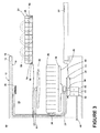
Figure 3 is a schematic view of the dishwasher ofFigure 1 with a dish holder in a load position. -
Figure 4 is a schematic view of a dishwasher with a dish holder having drawer slides. -
Figure 5A is a schematic view of a portion of the dishwasher ofFigure 4 with a dish holder in a load position. -
Figure 5B is a schematic view of another portion of the dishwasher ofFigure 4 with a dish holder in a load position. -
Figure 6 is a top view of an exemplary rack for use with one of the dishwashers inFigures 1 and4 . -
Figure 7 is a top view of an exemplary drawer for use with one of the dishwashers inFigures 1 and4 . -
Figure 8 is a cross-sectional view of the drawer ofFigure 7 . - Referring to
Figure 1 , anautomatic dishwasher 10 having acabinet 12 defining an interior is illustrated. Depending on whether thedishwasher 10 is a stand-alone or built-in, thecabinet 12 may be a chassis/frame with or without panels attached, respectively. Thedishwasher 10 shares many features of a conventional automatic dishwasher, which will not be described in detail herein except as necessary for a complete understanding of the invention. While the present invention is described in terms of a conventional dishwashing unit, it could also be implemented in other types of dishwashing units, such as in-sink dishwashers, multi-tub dishwashers, or drawer-type dishwashers. - A
controller 14 may be located within thecabinet 12 and may be operably coupled with various components of thedishwasher 10 to implement one or more cycles of operation. A control panel oruser interface 16 may be provided on thedishwasher 10 and coupled with thecontroller 14. Theuser interface 16 may include operational controls such as dials, lights, switches, and displays enabling a user to input commands, such as a cycle of operation, to thecontroller 14 and receive information. - A
tub 18 is located within thecabinet 12 and at least partially defines a treatingchamber 20 with an access opening in the form of an open face. A cover, illustrated as adoor 22, may be hingedly mounted to thecabinet 12 and may move between a closed position, as shown inFigure 1 , wherein thedoor 22 covers or closes the open face of the treatingchamber 20 and an opened position (Figure 3 ), wherein the user may access the treatingchamber 20. - Dish holders have been illustrated in the form of upper and
lower racks lower racks chamber 20 and receive dishes for being treated. The upper andlower racks chamber 20 for ease of loading and unloading. The upper andlower racks tub 18 through the open face between a loading position and a treating position. As used in this description, the term "dish(es)" is intended to be generic to any item, single or plural, that may be treated in thedishwasher 10, including, without limitation; utensils, plates, pots, bowls, pans, glassware, and silverware. While not shown, additional utensil holders, such as a silverware basket on the interior of thedoor 22, may also be provided. - A spraying
system 28 may be provided for spraying liquid into the treatingchamber 20 and is illustrated in the form of anupper sprayer 30, a mid-levelrotatable sprayer 32, a lowerrotatable spray arm 34, and aspray manifold 36. Theupper sprayer 30 may be located above theupper rack 24 and is illustrated as a fixed spray nozzle that sprays liquid downwardly within the treatingchamber 20. Mid-levelrotatable sprayer 32 and lowerrotatable spray arm 34 are located, respectively, beneathupper rack 24 andlower rack 26 and are illustrated as rotating spray arms. Themid-level spray arm 32 may provide a liquid spray upwardly through the bottom of theupper rack 24. The lowerrotatable spray arm 34 may provide a liquid spray upwardly through the bottom of thelower rack 26. The mid-levelrotatable sprayer 32 may optionally also provide a liquid spray downwardly onto thelower rack 26, but for purposes of simplification, this will not be illustrated herein. - The
spray manifold 36 may be fixedly mounted to thetub 18 adjacent to thelower rack 26 and may provide a liquid spray laterally through a side of thelower rack 26. Thespray manifold 36 may not be limited to this position; rather, thespray manifold 36 may be located in virtually any part of the treatingchamber 20. While not illustrated herein, thespray manifold 36 may include multiple spray nozzles having apertures configured to spray wash liquid towards thelower rack 26. The spray nozzles may be fixed or rotatable with respect to thetub 18. - A liquid recirculation system may be provided for recirculating liquid from the treating
chamber 20 to thespraying system 28. The recirculation system may include asump 38 and apump assembly 40. Thesump 38 collects the liquid sprayed in the treatingchamber 20 and may be formed by a sloped or recessed portion of abottom wall 42 of thetub 18. Thepump assembly 40 may include both adrain pump 44 and arecirculation pump 46. - The
drain pump 44 may draw liquid from thesump 38 and pump the liquid out of thedishwasher 10 to ahousehold drain line 48. Therecirculation pump 46 may draw liquid from thesump 38 and pump the liquid to thespraying system 28 to supply liquid into the treatingchamber 20. While thepump assembly 40 is illustrated as having separate drain and recirculation pumps 44, 46 in an alternative embodiment, thepump assembly 40 may include a single pump configured to selectively supply wash liquid to either thespraying system 28 or thedrain line 48, such as by configuring the pump to rotate in opposite directions, or by providing a suitable valve system. While not shown, a liquid supply system may include a water supply conduit coupled with a household water supply for supplying water to thesump 38. - As shown herein, the
recirculation pump 46 has anoutlet conduit 50 in fluid communication with thespraying system 28 for discharging wash liquid from therecirculation pump 46 to the sprayers 30-36. As illustrated, liquid may be supplied to thespray manifold 36, mid-levelrotatable sprayer 32, andupper sprayer 30 through asupply tube 52 that extends generally rearward from therecirculation pump 46 and upwardly along a rear wall of thetub 18. While thesupply tube 52 ultimately supplies liquid to thespray manifold 36, mid-levelrotatable sprayer 32, andupper sprayer 30, it may fluidly communicate with one or more manifold tubes that directly transport liquid to thespray manifold 36, mid-levelrotatable sprayer 32, andupper sprayer 30. Further, diverters (not shown) may be provided within thespraying system 28 such that liquid may be selectively supplied to each of the sprayers 30-36. The sprayers 30-36 spray water and/or treating chemistry onto thedish racks 24, 26 (and hence any dishes positioned thereon) to effect a recirculation of the liquid from the treatingchamber 20 to theliquid spraying system 28 to define a recirculation flow path. - A heating system having a
heater 54 may be located within or near thesump 38 for heating liquid contained in thesump 38. A filtering system (not shown) may be fluidly coupled with the recirculation flow path for filtering the recirculated liquid. - A
light source 56 may be provided on one or both of the upper andlower racks light source 56 has been illustrated in theupper rack 24 only for clarity purposes. However, each of the upper andlower dish racks lower dish racks light source 56 may include a plurality of light sources including that the plurality of light sources may include light emitting diodes (LEDs). In the illustrated example, thelight source 56 includes afirst light source 58 and a secondlight source 60. The first and secondlight sources wired connection 59. Both of thefirst light source 58 and the secondlight source 60 have been illustrated as including several LEDs. It will be understood that thelight source 56 may include any suitable light source and that any number of light sources may be provided on theupper rack 24 in any suitable location. Regardless of which of the upper andlower racks upper rack 24 and/orlower rack 26 to be illuminated while directing light away from the bottom of thetub 18, which may become dirty with use. - A
power source 62 may be coupled to thelight source 56 by an electrical conductor such as awire connection 64. Thepower source 62 has been illustrated as being located exteriorly of thetub 18 and thewire connection 64 has been illustrated as passing through thetub 18 and into the treatingchamber 20, although the wire connection need not pass through thetub 18. Alternatively, thepower source 62 may be located inside thetub 18. It is contemplated that thepower source 62 may be a self-contained power source or that it may be wired or wirelessly connected to a main power source. For example, if thepower source 62 is located within thetub 18 it may be inductively coupled to a power source located out of thetub 18. Alternatively, thepower source 62 may be entirely self-contained. For example, if thepower source 62 is located within thetub 18, it may include a battery pack, a flywheel, or a capacitor. - Regardless of whether the
power source 62 is located inside thetub 18 or outside thetub 18, thewire connection 64 may be provided with slack to enable theupper rack 24 to move at least partially out of the treatingchamber 20, such as to the loading position. Wherelight sources 56 are located on both theupper rack 24 and thelower rack 26, thelight sources 56 may be operably coupled to asingle power source 62 by separate wire connections, each provided with slack to enable the upper andlower dish racks chamber 20. Alternatively, thelight sources 56 may be operably coupled tomultiple power sources 62 byslack wire connections 64. - As illustrated in
Figure 2 , thecontroller 14 may be provided with amemory 66 and a central processing unit (CPU) 68. Thememory 66 may be used for storing control software that may be executed by theCPU 68 in completing a cycle of operation using thedishwasher 10 and any additional software. For example, thememory 66 may store one or more pre-programmed cycles of operation that may be selected by a user and completed by thedishwasher 10. A cycle of operation for thedishwasher 10 may include one or more of the following steps: a wash step, a rinse step, and a drying step. The wash step may further include a pre-wash step and a main wash step. The rinse step may also include multiple steps such as one or more additional rinsing steps performed in addition to a first rinsing. The amounts of water and/or rinse aid used during each of the multiple rinse steps may be varied. The drying step may have a non-heated drying step (so called "air only"), a heated drying step or a combination thereof. These multiple steps may also be performed by thedishwasher 10 in any desired combination. - The
controller 14 may be operably coupled with one or more components of thedishwasher 10 for communicating with and controlling the operation of the components to complete a cycle of operation. For example, thecontroller 14 may be coupled with therecirculation pump 46 for circulation of liquid in thetub 18 and thedrain pump 44 for drainage of liquid in thetub 18. Thecontroller 14 may also be operably coupled to theheater 54 and one or moreoptional sensors 70. Non-limiting examples ofoptional sensors 70 that may be communicably coupled with thecontroller 14 include a moisture sensor, a door sensor, a temperature sensor, a detergent and rinse aid presence/type sensor(s). Thecontroller 14 may also be coupled to adispenser 72, which may dispense a detergent during the wash step of the cycle of operation or a rinse aid during the rinse step of the cycle of operation. Further, thecontroller 14 may be operably coupled with thepower source 62 or the light source(s) 56 although this need not be the case. - During a wash and rinse portion of a cycle of operation of the
dishwasher 10, thedoor 22 is in a closed position, and the upper andlower racks chamber 20 in a use position, illustrated inFigure 1 , where they are exposed to washing fluid, such as water, and wash aids, such as detergents and rinse aids. When thedishwasher 10 is not in a portion of the cycle of operation, the user may move thedoor 22 to an open position and may move the upper andlower racks chamber 20 to a load position where at least a portion of theracks cabinet 12 and where the upper andlower racks Figure 3 , which shows thedoor 22 in the open position and theupper rack 24 in the load position; thelower rack 26 remains in the use position. As illustrated, thewire connection 64 becomes more taunt as theupper rack 24 is moved to the load position. Thelight sources 56 are illustrated as initially directing light towards dishes in theupper rack 24. -
Figure 4 illustrates a second embodiment of thedishwasher 110, with an alternativelight source 156/power source 162 configuration. The second embodiment is similar to the first embodiment as illustrated inFigure 1 . Therefore, like parts will be identified with like numerals increased by 100, with it being understood that the description of the like parts of the first embodiment applies to the second embodiment, unless otherwise noted. - In the illustrated example, the upper and
lower racks tub 118 by arail system 180. For thelower rack 126, therail system 180 may include a pair ofrails 182 formed on side walls of thetub 118 in alignment with the inner surface of thedoor 122 when thedoor 122 is in the open position such that thelower rack 126 may be moved out of the treatingchamber 120 over thedoor 122. Thelower rack 126 may be provided withwheels 184 which roll along therails 182 and allow thelower rack 126 to be rolled out at least partially onto the inner face of theopen door 122 and into the load position. - The
rail system 180 for theupper rack 124 may be slightly more complex and may include a set ofrails 186 on which theupper rack 124 may be movably supported and which in turn may be movably supported on the side walls of thetub 118. The set ofrails 186 may be positioned and capable of horizontal movement by support rollers (not shown) on the side wall of thetub 118. Theupper rack 124 has on each side at least two projectingrollers 188 that operably couple with the set ofrails 186 and allow theupper rack 124 to slide freely along the set ofrails 186. Thus, theupper rack 124 may roll along the set ofrails 186 as the set of rails186 rolls along the supporting rollers (not shown) so that theupper rack 124 may slide far enough with the set ofrails 186 to move completely out of the treatingchamber 120. - The
rail system 180 facilitates movement of the upper andlower racks rail system 180 permits the complete extension of the upper andlower racks tub 118, other rail systems may not. Any suitable rail system may be utilized and therail system 180 described herein is merely for exemplary purposes. It has been contemplated that any other type of slides or rail system or any other mechanism suitable for slidably coupling the dish holders to thetub 118 and facilitating movement of the dish holders between the use and load positions may be utilized. - As with the earlier embodiment at least one
light source 156 is provided in thedishwasher 110. In the illustrated example,light sources 156 have been illustrated as being provided on each of the upper andlower racks lower racks power source 162 may be selectively coupled to the light source(s) 156 by a contact connection 181 (Figure 5A andFigure 5B ) provided on therail system 180. Thecontact connection 181 may be closed to couple thepower source 162 to thelight source 156 when the upper andlower racks chamber 120. - With respect to the
light source 156 on theupper rack 124, thecontact connection 181 includes at least a portion of therail 186 of therail system 180 and aroller 188 of therail system 180. Thelight source 156 on theupper rack 124 may be operably coupled to theroller 188 of therail system 180 such as through aconnection 187. Thepower source 162 is operably coupled, directly, such as wired, or indirectly, such as wireless, including a capacitive coupling, to therail 186 of therail system 180. As with the earlier embodiment, thepower source 162 has been illustrated as being located exteriorly of thetub 118. Alternatively, thepower source 162 may be located inside thetub 118. It is contemplated that therail 186 may be directly or indirectly coupled, such as through induction, with thepower source 162. - As the
roller 188 makes contact with therail 186 thecontact connection 181 may be formed and thelight source 156 may be illuminated. So long as theroller 188 and therail 186 are in contact thecontact connection 181 may be closed to couple thepower source 162 to thelight source 156 including when theupper rack 124 is slid out of the treatingchamber 120, as shown inFigure 5A . Therail 186 and theroller 188 may also be formed such that thecontact connection 181 is only closed when theupper rack 124 is at least partially out of the treatingchamber 120. For example, a portion of therail 186 may be insulated so that thecontact connection 181 is not closed when theupper rack 124 is located inside the treatingchamber 120. In such an instance aconductive portion 189 of therail 186 would make acontact connection 181 with theroller 188 when theupper rack 124 is slid out of the treatingchamber 120. - With respect to the
lower rack 126, as illustrated inFigure 5B thecontact connection 181 includes aspring finger 190 that extends from thelower rack 126 and is operably coupled with thelight source 156. Thespring finger 190 of thecontact connection 181 may be in contact with a portion of thecontact connection 181 provided on therail system 180, such as aportion 192 of therail 182, when thelower rack 126 is in the loading position, as shown inFigure 5 . In this manner, thecontact connection 181 is closed when thelower rack 126 is in the loading position. - Where
light sources 156 are located on both theupper rack 124 and thelower rack 126, thelight sources 156 may be operably coupled tomultiple power sources 162 as illustrated or may be coupled to asingle power source 162 bycontact connections 181 provided on therail system 180 for each of the upper andlower dish racks - In both of the above illustrated examples, it is contemplated that the light source(s) may be provided on the upper and lower racks in any suitable manner including that the light source(s) may be attached to the upper and lower racks or may be integrated with the upper and lower racks. For example, the light source may be in the form of a light pipe that is integrated with the rack and forms a portion of one of the racks. For example,
Figure 6 illustrates that the light source is alight pipe 200 integrated in adish rack 202. In the dish rack 202 a portion of thedish rack 202 could be formed from thelight pipe 200 instead of one of thecoated wire elements 206 forming the traditional wire frame rack. In the illustrated example, thelight pipe 200 forms a portion of the topmost wire element of the wire frame rack. Thedish rack 202 has four sides, including afront side 224 and aback side 226 joined by twolateral sides 228. In the illustrated example, thelight pipe 200 extends along the back andlateral sides dish rack 202. Instead of asingle light pipe 200 several light pipes may be used. Thelight pipe 200 may be operably coupled with apower source 204, which may be inside or outside thetub 232 including by way of one of the above examples. Alternatively, thelight pipe 200 may be operably coupled with a battery or other mechanism located near thelight pipe 200 on thedish rack 202. - Furthermore, the dishwashers above may include drawers instead of dish racks. In models that have a drawer, the light source could be integrated into portions of the drawer. In such an instance the light source may be either insert-molded or attached separately to the portions of the drawer. When using an insert-molded light source, the drawer is molded as well. For example,
Figure 7 illustrates that dish holder may be in the form of adrawer 210. Thedrawer 210 may include aninner wall 212 spaced from anouter wall 214, apan 216 may form a portion of the bottom of thedrawer 210 and arack 218 may be positioned within thedrawer 210. Alight source 220 may be molded to fit in thecavity 208 between theinner wall 212 and theouter wall 214 of thedrawer 210. Further, alight source 222 may be provided on thepan 216. Thelight sources power source 230, which may be inside or outside thetub 232 including by way of one of the above examples. Alternatively, thelight sources drawer 210. The cross-sectional view illustrated inFigure 8 better illustrates the position of thelight source 220 in thecavity 208 between theinner wall 212 and theouter wall 214 of thedrawer 210. Thelight source 220 may form a portion of theinner wall 212 or may be placed behind atransparent section 234 of theinner wall 212 so that light may be directed towards dishes in therack 218. - Furthermore, any of the dishwashers described above may include a light source in the form of multi-colored LEDs. The LEDs may automatically change color to indicate a status of the dishwasher to the user. For example, the color may indicate the cleanliness of the dishes loaded into the dishwasher. Before a cycle of operation is started, a user may open the door one or more times to load dishes into the treating chamber. Each time the user opens the door the LEDs may emit a first color, such as red, to indicate that a cycle of operation has not been run and that the dishes are dirty. After a cycle of operation has been run, when the user opens the door, the LEDs may emit a second color, such as blue or white, to indicate that the cycle of operation is complete and that the dishes are clean. In another implementation, the color emitted by the LEDs may be manually controllable or settable by the user according to the user's preference. The user may be able to set the color of light emitted by the LEDs via the user interface.
- Currently, lights mounted in dishwashers create a path for leakage from the dishwasher and are positioned to light areas of the tub, rather than specifically lighting the dishes. Also, lights on the tub can collect food soil. There are several advantages of the present disclosure arising from the various features of the apparatuses described herein. For example, the embodiments described above allow for dishes in the dish holders to be illuminated regardless of the position of the dish holder. The embodiments described above also allow for various ways to power light sources provided on the dish holders. Further, integration of the lights into dish holders may eliminate the need for separate assemblies, which are mounted on the tub that can collect food soils or make leak paths. Further, providing light sources in the dish holders leaves more capacity space in the tub for dishes.
- While the invention has been specifically described in connection with certain specific embodiments thereof, it is to be understood that this is by way of illustration and not of limitation. The patentable scope of the invention is defined by the claims, and may include other examples that occur to those skilled in the art. It will be understood that any features of the above described embodiments may be combined in any manner. Reasonable variation and modification are possible within the scope of the forgoing disclosure and drawings without departing from the spirit of the invention which is defined in the appended claims.
Claims (15)
- A dishwasher for treating dishes according to an automatic cycle of operation, comprising:a tub at least partially defining a treating chamber for receiving dishes for treatment according to the cycle of operation and having an open face providing access to the treating chamber;a dish holder slidable relative to the tub through the open face between a loading position and a treating position;a light source provided on the dish holder for illuminating dishes contained in the dish holder.
- A dishwasher according to claim 1 further comprising a power source coupled to the light source by an electrical conductor where the electrical conductor is provided with slack to enable the dish holder to move at least partially out of the treating chamber.
- The dishwasher of claim 2 wherein the power source is located exteriorly of the tub, optionally wherein the electrical conductor passes through a portion of the tub.
- The dishwasher of claim 1, 2 or 3, wherein the light source includes a plurality of light sources, for example comprising light emitting diodes.
- A dishwasher according to claim 1, comprising:a rail system slidably coupling the dish holder to the tub for movement relative to the treating chamber; anda power source selectively coupled to the light source by a contact connection provided on the rail system where the contact connection is closed to couple the power source to the light source when the dish holder is slid at least partially out of the treating chamber.
- The dishwasher of claim 5 wherein the contact connection comprises a rail of the rail system and a roller of the rail system, for example wherein the light source is operably coupled to the roller of the rail system and the power source is operably coupled to the rail of the rail system.
- The dishwasher of claim 5 wherein the contact connection comprises a spring finger that extends from the dish holder and is operably coupled with the light source, optionally wherein the spring finger is in contact with a portion of the contact connection provided on the rail system when the dish holder is in the loading position.
- The dishwasher according to any one of the preceding claims wherein the light source is directed away from a bottom of the tub, preferably to initially upwardly direct at least a portion of the light emitted by the light source.
- A dishwasher according to claim 1 wherein the light source is a light pipe integrally formed with the dish holder for illuminating dishes contained in the dish holder.
- The dishwasher of claim 9 wherein either: (a) the dish rack comprises a wire frame having multiple wire elements, and the light pipe forms one of the wire elements; (b) the dish rack has four sides, each comprising multiple wire elements, and wherein the light pipe forms at least a portion of a topmost wire element of at least one of the four sides; (c) the dish rack has four sides, and the light pipe extends along at least two of the four sides; (d) wherein the dish rack has our sides and the light pipe extends along at least three of the four sides; or (e) wherein the four sides of the dish rack comprise a front side and a rear side joined by two lateral sides, and the light pipe extends along the rear and lateral sides.
- The dishwasher according to any one of the preceding claims wherein the dish holder comprises a drawer having a pan or a dish rack, optionally wherein the light source is provided on or integrally formed with the dish rack or pan.
- A dishwasher according to claim 1 wherein the dish holder comprises a drawer slidable relative to the tub through the open face between a loading position and a treating position, and having an outer wall and an inner wall spaced from the outer wall to define a cavity; and
the light source is provided within the cavity for illuminating dishes contained in the dish holder. - The dishwasher of claim 12 wherein either (a): the light source forms a portion of the inner wall; (b) the inner wall comprises a transparent section, and the light source is provided behind the transparent section; or (c) the drawer comprises a pan forming a portion of the bottom of the drawer, and further comprising a second light source provided on the pan.
- A dishwasher according to any one of the preceding claims wherein the dish holder is a molded dish holder slidable relative to the tub through the open face between a loading position and a treating position and the light source is an insert-molded light source provided with the dish holder for illuminating dishes contained in the dish holder.
- The dishwasher of claim 14 wherein the dish holder comprises a drawer, optionally wherein the drawer comprises an outer wall and an inner wall spaced from the outer wall to define a cavity, and the light source is molded to fit in the cavity.
Priority Applications (1)
| Application Number | Priority Date | Filing Date | Title |
|---|---|---|---|
| PL14164066T PL2803311T3 (en) | 2013-05-16 | 2014-04-09 | Dishwasher with integrated lighting |
Applications Claiming Priority (2)
| Application Number | Priority Date | Filing Date | Title |
|---|---|---|---|
| US201361823940P | 2013-05-16 | 2013-05-16 | |
| US14/221,643 US10022036B2 (en) | 2013-05-16 | 2014-03-21 | Dishwasher with integrated lighting |
Publications (2)
| Publication Number | Publication Date |
|---|---|
| EP2803311A1 true EP2803311A1 (en) | 2014-11-19 |
| EP2803311B1 EP2803311B1 (en) | 2016-11-02 |
Family
ID=50473112
Family Applications (1)
| Application Number | Title | Priority Date | Filing Date |
|---|---|---|---|
| EP14164066.4A Not-in-force EP2803311B1 (en) | 2013-05-16 | 2014-04-09 | Dishwasher with integrated lighting |
Country Status (3)
| Country | Link |
|---|---|
| US (2) | US10022036B2 (en) |
| EP (1) | EP2803311B1 (en) |
| PL (1) | PL2803311T3 (en) |
Cited By (2)
| Publication number | Priority date | Publication date | Assignee | Title |
|---|---|---|---|---|
| EP3320823A1 (en) * | 2016-11-14 | 2018-05-16 | BSH Hausgeräte GmbH | Dishwasher and method for operating a dishwasher |
| EP3459422A1 (en) * | 2017-09-21 | 2019-03-27 | Vestel Elektronik Sanayi ve Ticaret A.S. | Dishwashing machine |
Families Citing this family (6)
| Publication number | Priority date | Publication date | Assignee | Title |
|---|---|---|---|---|
| DE102015108734A1 (en) | 2015-06-02 | 2016-12-08 | Friedrich Ug (Haftungsbeschränkt) | Holding block for a cutlery tray system for one or more cutlery and cutlery tray system with at least two holding blocks |
| KR102639692B1 (en) * | 2015-12-03 | 2024-02-23 | 삼성전자주식회사 | Tub for dishwasher, dishwasher and control method thereof |
| US20180087779A1 (en) * | 2016-09-28 | 2018-03-29 | Sandra Maldonado | Oven with Automatic Racks and Door |
| US10022035B2 (en) | 2016-12-08 | 2018-07-17 | Whirlpool Corporation | Dishwasher illuminating system |
| US10264944B2 (en) | 2017-08-22 | 2019-04-23 | Whirlpool Corporation | Light source for a dishwasher |
| US11019691B1 (en) * | 2020-01-17 | 2021-05-25 | B/E Aerospace, Inc. | Galley insert multi-purpose LED system |
Citations (4)
| Publication number | Priority date | Publication date | Assignee | Title |
|---|---|---|---|---|
| DE102010015849B3 (en) * | 2010-03-08 | 2011-04-07 | Miele & Cie. Kg | Dishwasher, has washing area accommodating loading unit, which is partly moved out from washing area by washing area opening, where loading unit exhibits lighting unit that exhibits set of illuminants i.e. LEDs |
| EP2543307A1 (en) * | 2011-07-06 | 2013-01-09 | BSH Bosch und Siemens Hausgeräte GmbH | Dishwasher, in particular domestic dishwasher, with at least one light-emitting passive illuminant in the interior |
| DE102011122897A1 (en) * | 2011-07-06 | 2013-03-21 | BSH Bosch und Siemens Hausgeräte GmbH | Dishwasher with at least one movably mounted on the washing container component at least comprising a light guide |
| EP2581026A2 (en) * | 2011-10-13 | 2013-04-17 | BSH Bosch und Siemens Hausgeräte GmbH | Dishwasher with at least one light element on at least one loading unit |
Family Cites Families (8)
| Publication number | Priority date | Publication date | Assignee | Title |
|---|---|---|---|---|
| US2836669A (en) | 1955-05-09 | 1958-05-27 | Gaylord Prod Inc | Electric switch for linkages |
| US5836669A (en) | 1996-01-17 | 1998-11-17 | Troy Investments, Inc. | Remote illumination and light apportionment in appliances |
| US20030022739A1 (en) * | 2001-07-26 | 2003-01-30 | Todd Vannoy | Ball launcher |
| US6958693B2 (en) * | 2002-05-24 | 2005-10-25 | Procter & Gamble Company | Sensor device and methods for using same |
| DE10236718A1 (en) * | 2002-08-06 | 2004-02-12 | E.G.O. Control Systems Gmbh & Co. Kg | Washing machine, tumble drier or dishwasher with optical display for operating data has panel with section of reduced thickness, on which display is mounted, and light source below it |
| DE102004051174A1 (en) | 2004-10-20 | 2006-05-04 | BSH Bosch und Siemens Hausgeräte GmbH | Lighting device for a water-conducting household appliance |
| EP2394557B1 (en) | 2010-03-18 | 2013-05-08 | Miele & Cie. KG | Dishwasher with a lighting system |
| EP2366323A1 (en) | 2010-03-18 | 2011-09-21 | Miele & Cie. KG | Dishwasher with a lighting device |
-
2014
- 2014-03-21 US US14/221,643 patent/US10022036B2/en active Active
- 2014-04-09 PL PL14164066T patent/PL2803311T3/en unknown
- 2014-04-09 EP EP14164066.4A patent/EP2803311B1/en not_active Not-in-force
-
2018
- 2018-05-16 US US15/980,873 patent/US10390682B2/en active Active
Patent Citations (4)
| Publication number | Priority date | Publication date | Assignee | Title |
|---|---|---|---|---|
| DE102010015849B3 (en) * | 2010-03-08 | 2011-04-07 | Miele & Cie. Kg | Dishwasher, has washing area accommodating loading unit, which is partly moved out from washing area by washing area opening, where loading unit exhibits lighting unit that exhibits set of illuminants i.e. LEDs |
| EP2543307A1 (en) * | 2011-07-06 | 2013-01-09 | BSH Bosch und Siemens Hausgeräte GmbH | Dishwasher, in particular domestic dishwasher, with at least one light-emitting passive illuminant in the interior |
| DE102011122897A1 (en) * | 2011-07-06 | 2013-03-21 | BSH Bosch und Siemens Hausgeräte GmbH | Dishwasher with at least one movably mounted on the washing container component at least comprising a light guide |
| EP2581026A2 (en) * | 2011-10-13 | 2013-04-17 | BSH Bosch und Siemens Hausgeräte GmbH | Dishwasher with at least one light element on at least one loading unit |
Cited By (2)
| Publication number | Priority date | Publication date | Assignee | Title |
|---|---|---|---|---|
| EP3320823A1 (en) * | 2016-11-14 | 2018-05-16 | BSH Hausgeräte GmbH | Dishwasher and method for operating a dishwasher |
| EP3459422A1 (en) * | 2017-09-21 | 2019-03-27 | Vestel Elektronik Sanayi ve Ticaret A.S. | Dishwashing machine |
Also Published As
| Publication number | Publication date |
|---|---|
| US10022036B2 (en) | 2018-07-17 |
| EP2803311B1 (en) | 2016-11-02 |
| US20140338708A1 (en) | 2014-11-20 |
| US10390682B2 (en) | 2019-08-27 |
| US20180256005A1 (en) | 2018-09-13 |
| PL2803311T3 (en) | 2017-07-31 |
Similar Documents
| Publication | Publication Date | Title |
|---|---|---|
| US10390682B2 (en) | Dishwasher with integrated lighting | |
| US10076224B2 (en) | Dishwasher | |
| US8696827B2 (en) | Dishwasher with imaging device for measuring load characteristics and a method for controlling same | |
| US9655496B2 (en) | Dishwasher with sprayer | |
| US9451862B2 (en) | Dishwasher with unitary wash module | |
| US8043437B1 (en) | Dishwasher with multiple treating chambers | |
| US9532700B2 (en) | Dishwasher with overflow conduit | |
| US20120138106A1 (en) | Dishwasher with single valve to fill multiple compartments | |
| US9713414B2 (en) | Dishwasher having a conduit framework | |
| US20150164299A1 (en) | Dishwasher with sprayer | |
| US20140083472A1 (en) | Adjustable multi-compartment dishwasher | |
| US20140137909A1 (en) | Dishwasher with sprayer | |
| EP2898809B1 (en) | Dishwasher | |
| US9532697B2 (en) | Dishwasher with unitary wash module | |
| EP4162857B1 (en) | Dishwasher with drain assembly | |
| EP3181033B1 (en) | Dish treating appliance with self-draining feedtube | |
| US11857135B2 (en) | Dishwasher with rack | |
| US10314460B2 (en) | Diverter valve and dishwasher with diverter valve | |
| US12053134B2 (en) | Dishwasher | |
| US20240215798A1 (en) | Dishwasher and rack assembly |
Legal Events
| Date | Code | Title | Description |
|---|---|---|---|
| PUAI | Public reference made under article 153(3) epc to a published international application that has entered the european phase |
Free format text: ORIGINAL CODE: 0009012 |
|
| 17P | Request for examination filed |
Effective date: 20140409 |
|
| AK | Designated contracting states |
Kind code of ref document: A1 Designated state(s): AL AT BE BG CH CY CZ DE DK EE ES FI FR GB GR HR HU IE IS IT LI LT LU LV MC MK MT NL NO PL PT RO RS SE SI SK SM TR |
|
| AX | Request for extension of the european patent |
Extension state: BA ME |
|
| R17P | Request for examination filed (corrected) |
Effective date: 20150518 |
|
| RBV | Designated contracting states (corrected) |
Designated state(s): AL AT BE BG CH CY CZ DE DK EE ES FI FR GB GR HR HU IE IS IT LI LT LU LV MC MK MT NL NO PL PT RO RS SE SI SK SM TR |
|
| GRAP | Despatch of communication of intention to grant a patent |
Free format text: ORIGINAL CODE: EPIDOSNIGR1 |
|
| RIC1 | Information provided on ipc code assigned before grant |
Ipc: A47L 15/50 20060101AFI20160425BHEP Ipc: A47L 15/42 20060101ALI20160425BHEP |
|
| INTG | Intention to grant announced |
Effective date: 20160530 |
|
| GRAS | Grant fee paid |
Free format text: ORIGINAL CODE: EPIDOSNIGR3 |
|
| GRAA | (expected) grant |
Free format text: ORIGINAL CODE: 0009210 |
|
| AK | Designated contracting states |
Kind code of ref document: B1 Designated state(s): AL AT BE BG CH CY CZ DE DK EE ES FI FR GB GR HR HU IE IS IT LI LT LU LV MC MK MT NL NO PL PT RO RS SE SI SK SM TR |
|
| REG | Reference to a national code |
Ref country code: GB Ref legal event code: FG4D |
|
| REG | Reference to a national code |
Ref country code: AT Ref legal event code: REF Ref document number: 840952 Country of ref document: AT Kind code of ref document: T Effective date: 20161115 Ref country code: CH Ref legal event code: EP |
|
| REG | Reference to a national code |
Ref country code: IE Ref legal event code: FG4D |
|
| REG | Reference to a national code |
Ref country code: DE Ref legal event code: R096 Ref document number: 602014004551 Country of ref document: DE |
|
| PG25 | Lapsed in a contracting state [announced via postgrant information from national office to epo] |
Ref country code: LV Free format text: LAPSE BECAUSE OF FAILURE TO SUBMIT A TRANSLATION OF THE DESCRIPTION OR TO PAY THE FEE WITHIN THE PRESCRIBED TIME-LIMIT Effective date: 20161102 |
|
| REG | Reference to a national code |
Ref country code: NL Ref legal event code: MP Effective date: 20161102 |
|
| REG | Reference to a national code |
Ref country code: LT Ref legal event code: MG4D |
|
| REG | Reference to a national code |
Ref country code: FR Ref legal event code: PLFP Year of fee payment: 4 |
|
| REG | Reference to a national code |
Ref country code: AT Ref legal event code: MK05 Ref document number: 840952 Country of ref document: AT Kind code of ref document: T Effective date: 20161102 |
|
| PG25 | Lapsed in a contracting state [announced via postgrant information from national office to epo] |
Ref country code: LT Free format text: LAPSE BECAUSE OF FAILURE TO SUBMIT A TRANSLATION OF THE DESCRIPTION OR TO PAY THE FEE WITHIN THE PRESCRIBED TIME-LIMIT Effective date: 20161102 Ref country code: NL Free format text: LAPSE BECAUSE OF FAILURE TO SUBMIT A TRANSLATION OF THE DESCRIPTION OR TO PAY THE FEE WITHIN THE PRESCRIBED TIME-LIMIT Effective date: 20161102 Ref country code: SE Free format text: LAPSE BECAUSE OF FAILURE TO SUBMIT A TRANSLATION OF THE DESCRIPTION OR TO PAY THE FEE WITHIN THE PRESCRIBED TIME-LIMIT Effective date: 20161102 Ref country code: NO Free format text: LAPSE BECAUSE OF FAILURE TO SUBMIT A TRANSLATION OF THE DESCRIPTION OR TO PAY THE FEE WITHIN THE PRESCRIBED TIME-LIMIT Effective date: 20170202 Ref country code: GR Free format text: LAPSE BECAUSE OF FAILURE TO SUBMIT A TRANSLATION OF THE DESCRIPTION OR TO PAY THE FEE WITHIN THE PRESCRIBED TIME-LIMIT Effective date: 20170203 |
|
| PG25 | Lapsed in a contracting state [announced via postgrant information from national office to epo] |
Ref country code: FI Free format text: LAPSE BECAUSE OF FAILURE TO SUBMIT A TRANSLATION OF THE DESCRIPTION OR TO PAY THE FEE WITHIN THE PRESCRIBED TIME-LIMIT Effective date: 20161102 Ref country code: ES Free format text: LAPSE BECAUSE OF FAILURE TO SUBMIT A TRANSLATION OF THE DESCRIPTION OR TO PAY THE FEE WITHIN THE PRESCRIBED TIME-LIMIT Effective date: 20161102 Ref country code: IS Free format text: LAPSE BECAUSE OF FAILURE TO SUBMIT A TRANSLATION OF THE DESCRIPTION OR TO PAY THE FEE WITHIN THE PRESCRIBED TIME-LIMIT Effective date: 20170302 Ref country code: AT Free format text: LAPSE BECAUSE OF FAILURE TO SUBMIT A TRANSLATION OF THE DESCRIPTION OR TO PAY THE FEE WITHIN THE PRESCRIBED TIME-LIMIT Effective date: 20161102 Ref country code: HR Free format text: LAPSE BECAUSE OF FAILURE TO SUBMIT A TRANSLATION OF THE DESCRIPTION OR TO PAY THE FEE WITHIN THE PRESCRIBED TIME-LIMIT Effective date: 20161102 Ref country code: RS Free format text: LAPSE BECAUSE OF FAILURE TO SUBMIT A TRANSLATION OF THE DESCRIPTION OR TO PAY THE FEE WITHIN THE PRESCRIBED TIME-LIMIT Effective date: 20161102 Ref country code: PT Free format text: LAPSE BECAUSE OF FAILURE TO SUBMIT A TRANSLATION OF THE DESCRIPTION OR TO PAY THE FEE WITHIN THE PRESCRIBED TIME-LIMIT Effective date: 20170302 |
|
| PG25 | Lapsed in a contracting state [announced via postgrant information from national office to epo] |
Ref country code: RO Free format text: LAPSE BECAUSE OF FAILURE TO SUBMIT A TRANSLATION OF THE DESCRIPTION OR TO PAY THE FEE WITHIN THE PRESCRIBED TIME-LIMIT Effective date: 20161102 Ref country code: DK Free format text: LAPSE BECAUSE OF FAILURE TO SUBMIT A TRANSLATION OF THE DESCRIPTION OR TO PAY THE FEE WITHIN THE PRESCRIBED TIME-LIMIT Effective date: 20161102 Ref country code: CZ Free format text: LAPSE BECAUSE OF FAILURE TO SUBMIT A TRANSLATION OF THE DESCRIPTION OR TO PAY THE FEE WITHIN THE PRESCRIBED TIME-LIMIT Effective date: 20161102 Ref country code: SK Free format text: LAPSE BECAUSE OF FAILURE TO SUBMIT A TRANSLATION OF THE DESCRIPTION OR TO PAY THE FEE WITHIN THE PRESCRIBED TIME-LIMIT Effective date: 20161102 Ref country code: EE Free format text: LAPSE BECAUSE OF FAILURE TO SUBMIT A TRANSLATION OF THE DESCRIPTION OR TO PAY THE FEE WITHIN THE PRESCRIBED TIME-LIMIT Effective date: 20161102 |
|
| REG | Reference to a national code |
Ref country code: DE Ref legal event code: R097 Ref document number: 602014004551 Country of ref document: DE |
|
| PG25 | Lapsed in a contracting state [announced via postgrant information from national office to epo] |
Ref country code: BE Free format text: LAPSE BECAUSE OF FAILURE TO SUBMIT A TRANSLATION OF THE DESCRIPTION OR TO PAY THE FEE WITHIN THE PRESCRIBED TIME-LIMIT Effective date: 20161102 Ref country code: SM Free format text: LAPSE BECAUSE OF FAILURE TO SUBMIT A TRANSLATION OF THE DESCRIPTION OR TO PAY THE FEE WITHIN THE PRESCRIBED TIME-LIMIT Effective date: 20161102 Ref country code: BG Free format text: LAPSE BECAUSE OF FAILURE TO SUBMIT A TRANSLATION OF THE DESCRIPTION OR TO PAY THE FEE WITHIN THE PRESCRIBED TIME-LIMIT Effective date: 20170202 |
|
| PLBE | No opposition filed within time limit |
Free format text: ORIGINAL CODE: 0009261 |
|
| STAA | Information on the status of an ep patent application or granted ep patent |
Free format text: STATUS: NO OPPOSITION FILED WITHIN TIME LIMIT |
|
| 26N | No opposition filed |
Effective date: 20170803 |
|
| PG25 | Lapsed in a contracting state [announced via postgrant information from national office to epo] |
Ref country code: SI Free format text: LAPSE BECAUSE OF FAILURE TO SUBMIT A TRANSLATION OF THE DESCRIPTION OR TO PAY THE FEE WITHIN THE PRESCRIBED TIME-LIMIT Effective date: 20161102 |
|
| REG | Reference to a national code |
Ref country code: CH Ref legal event code: PL |
|
| REG | Reference to a national code |
Ref country code: IE Ref legal event code: MM4A |
|
| PG25 | Lapsed in a contracting state [announced via postgrant information from national office to epo] |
Ref country code: MC Free format text: LAPSE BECAUSE OF FAILURE TO SUBMIT A TRANSLATION OF THE DESCRIPTION OR TO PAY THE FEE WITHIN THE PRESCRIBED TIME-LIMIT Effective date: 20161102 |
|
| PG25 | Lapsed in a contracting state [announced via postgrant information from national office to epo] |
Ref country code: LI Free format text: LAPSE BECAUSE OF NON-PAYMENT OF DUE FEES Effective date: 20170430 Ref country code: LU Free format text: LAPSE BECAUSE OF NON-PAYMENT OF DUE FEES Effective date: 20170409 Ref country code: CH Free format text: LAPSE BECAUSE OF NON-PAYMENT OF DUE FEES Effective date: 20170430 |
|
| REG | Reference to a national code |
Ref country code: FR Ref legal event code: PLFP Year of fee payment: 5 |
|
| PG25 | Lapsed in a contracting state [announced via postgrant information from national office to epo] |
Ref country code: IE Free format text: LAPSE BECAUSE OF NON-PAYMENT OF DUE FEES Effective date: 20170409 |
|
| PG25 | Lapsed in a contracting state [announced via postgrant information from national office to epo] |
Ref country code: MT Free format text: LAPSE BECAUSE OF NON-PAYMENT OF DUE FEES Effective date: 20170409 |
|
| PGFP | Annual fee paid to national office [announced via postgrant information from national office to epo] |
Ref country code: PL Payment date: 20190312 Year of fee payment: 6 |
|
| PG25 | Lapsed in a contracting state [announced via postgrant information from national office to epo] |
Ref country code: HU Free format text: LAPSE BECAUSE OF FAILURE TO SUBMIT A TRANSLATION OF THE DESCRIPTION OR TO PAY THE FEE WITHIN THE PRESCRIBED TIME-LIMIT; INVALID AB INITIO Effective date: 20140409 |
|
| PG25 | Lapsed in a contracting state [announced via postgrant information from national office to epo] |
Ref country code: CY Free format text: LAPSE BECAUSE OF FAILURE TO SUBMIT A TRANSLATION OF THE DESCRIPTION OR TO PAY THE FEE WITHIN THE PRESCRIBED TIME-LIMIT Effective date: 20161102 |
|
| PG25 | Lapsed in a contracting state [announced via postgrant information from national office to epo] |
Ref country code: MK Free format text: LAPSE BECAUSE OF FAILURE TO SUBMIT A TRANSLATION OF THE DESCRIPTION OR TO PAY THE FEE WITHIN THE PRESCRIBED TIME-LIMIT Effective date: 20161102 |
|
| PG25 | Lapsed in a contracting state [announced via postgrant information from national office to epo] |
Ref country code: TR Free format text: LAPSE BECAUSE OF FAILURE TO SUBMIT A TRANSLATION OF THE DESCRIPTION OR TO PAY THE FEE WITHIN THE PRESCRIBED TIME-LIMIT Effective date: 20161102 |
|
| PG25 | Lapsed in a contracting state [announced via postgrant information from national office to epo] |
Ref country code: AL Free format text: LAPSE BECAUSE OF FAILURE TO SUBMIT A TRANSLATION OF THE DESCRIPTION OR TO PAY THE FEE WITHIN THE PRESCRIBED TIME-LIMIT Effective date: 20161102 |
|
| PG25 | Lapsed in a contracting state [announced via postgrant information from national office to epo] |
Ref country code: PL Free format text: LAPSE BECAUSE OF NON-PAYMENT OF DUE FEES Effective date: 20200409 |
|
| P01 | Opt-out of the competence of the unified patent court (upc) registered |
Effective date: 20230522 |
|
| REG | Reference to a national code |
Ref country code: DE Ref legal event code: R082 Ref document number: 602014004551 Country of ref document: DE Representative=s name: SEIDE, CHRISTIAN, DIPL.-PHYS.(ETH ZUERICH) DR., DE |
|
| PGFP | Annual fee paid to national office [announced via postgrant information from national office to epo] |
Ref country code: GB Payment date: 20240423 Year of fee payment: 11 |
|
| PGFP | Annual fee paid to national office [announced via postgrant information from national office to epo] |
Ref country code: DE Payment date: 20240429 Year of fee payment: 11 |
|
| PGFP | Annual fee paid to national office [announced via postgrant information from national office to epo] |
Ref country code: IT Payment date: 20240423 Year of fee payment: 11 Ref country code: FR Payment date: 20240430 Year of fee payment: 11 |
|
| REG | Reference to a national code |
Ref country code: DE Ref legal event code: R119 Ref document number: 602014004551 Country of ref document: DE |
|
| GBPC | Gb: european patent ceased through non-payment of renewal fee |
Effective date: 20250409 |
|
| PG25 | Lapsed in a contracting state [announced via postgrant information from national office to epo] |
Ref country code: DE Free format text: LAPSE BECAUSE OF NON-PAYMENT OF DUE FEES Effective date: 20251104 |
|
| PG25 | Lapsed in a contracting state [announced via postgrant information from national office to epo] |
Ref country code: GB Free format text: LAPSE BECAUSE OF NON-PAYMENT OF DUE FEES Effective date: 20250409 |
|
| PG25 | Lapsed in a contracting state [announced via postgrant information from national office to epo] |
Ref country code: FR Free format text: LAPSE BECAUSE OF NON-PAYMENT OF DUE FEES Effective date: 20250430 |
|
| PG25 | Lapsed in a contracting state [announced via postgrant information from national office to epo] |
Ref country code: IT Free format text: LAPSE BECAUSE OF NON-PAYMENT OF DUE FEES Effective date: 20250409 |