EP2802813B1 - Heat dissipation device and illumination apparatus comprising the heat dissipation device - Google Patents
Heat dissipation device and illumination apparatus comprising the heat dissipation device Download PDFInfo
- Publication number
- EP2802813B1 EP2802813B1 EP13723690.7A EP13723690A EP2802813B1 EP 2802813 B1 EP2802813 B1 EP 2802813B1 EP 13723690 A EP13723690 A EP 13723690A EP 2802813 B1 EP2802813 B1 EP 2802813B1
- Authority
- EP
- European Patent Office
- Prior art keywords
- fins
- heat dissipation
- dissipation device
- section
- illumination apparatus
- Prior art date
- Legal status (The legal status is an assumption and is not a legal conclusion. Google has not performed a legal analysis and makes no representation as to the accuracy of the status listed.)
- Active
Links
Images

Classifications
-
- F—MECHANICAL ENGINEERING; LIGHTING; HEATING; WEAPONS; BLASTING
- F21—LIGHTING
- F21V—FUNCTIONAL FEATURES OR DETAILS OF LIGHTING DEVICES OR SYSTEMS THEREOF; STRUCTURAL COMBINATIONS OF LIGHTING DEVICES WITH OTHER ARTICLES, NOT OTHERWISE PROVIDED FOR
- F21V29/00—Protecting lighting devices from thermal damage; Cooling or heating arrangements specially adapted for lighting devices or systems
- F21V29/50—Cooling arrangements
- F21V29/70—Cooling arrangements characterised by passive heat-dissipating elements, e.g. heat-sinks
- F21V29/74—Cooling arrangements characterised by passive heat-dissipating elements, e.g. heat-sinks with fins or blades
- F21V29/77—Cooling arrangements characterised by passive heat-dissipating elements, e.g. heat-sinks with fins or blades with essentially identical diverging planar fins or blades, e.g. with fan-like or star-like cross-section
- F21V29/773—Cooling arrangements characterised by passive heat-dissipating elements, e.g. heat-sinks with fins or blades with essentially identical diverging planar fins or blades, e.g. with fan-like or star-like cross-section the planes containing the fins or blades having the direction of the light emitting axis
-
- F—MECHANICAL ENGINEERING; LIGHTING; HEATING; WEAPONS; BLASTING
- F21—LIGHTING
- F21V—FUNCTIONAL FEATURES OR DETAILS OF LIGHTING DEVICES OR SYSTEMS THEREOF; STRUCTURAL COMBINATIONS OF LIGHTING DEVICES WITH OTHER ARTICLES, NOT OTHERWISE PROVIDED FOR
- F21V29/00—Protecting lighting devices from thermal damage; Cooling or heating arrangements specially adapted for lighting devices or systems
- F21V29/50—Cooling arrangements
- F21V29/70—Cooling arrangements characterised by passive heat-dissipating elements, e.g. heat-sinks
- F21V29/83—Cooling arrangements characterised by passive heat-dissipating elements, e.g. heat-sinks the elements having apertures, ducts or channels, e.g. heat radiation holes
-
- F—MECHANICAL ENGINEERING; LIGHTING; HEATING; WEAPONS; BLASTING
- F21—LIGHTING
- F21V—FUNCTIONAL FEATURES OR DETAILS OF LIGHTING DEVICES OR SYSTEMS THEREOF; STRUCTURAL COMBINATIONS OF LIGHTING DEVICES WITH OTHER ARTICLES, NOT OTHERWISE PROVIDED FOR
- F21V29/00—Protecting lighting devices from thermal damage; Cooling or heating arrangements specially adapted for lighting devices or systems
- F21V29/50—Cooling arrangements
- F21V29/502—Cooling arrangements characterised by the adaptation for cooling of specific components
- F21V29/507—Cooling arrangements characterised by the adaptation for cooling of specific components of means for protecting lighting devices from damage, e.g. housings
-
- F—MECHANICAL ENGINEERING; LIGHTING; HEATING; WEAPONS; BLASTING
- F21—LIGHTING
- F21V—FUNCTIONAL FEATURES OR DETAILS OF LIGHTING DEVICES OR SYSTEMS THEREOF; STRUCTURAL COMBINATIONS OF LIGHTING DEVICES WITH OTHER ARTICLES, NOT OTHERWISE PROVIDED FOR
- F21V29/00—Protecting lighting devices from thermal damage; Cooling or heating arrangements specially adapted for lighting devices or systems
- F21V29/50—Cooling arrangements
- F21V29/70—Cooling arrangements characterised by passive heat-dissipating elements, e.g. heat-sinks
- F21V29/74—Cooling arrangements characterised by passive heat-dissipating elements, e.g. heat-sinks with fins or blades
- F21V29/75—Cooling arrangements characterised by passive heat-dissipating elements, e.g. heat-sinks with fins or blades with fins or blades having different shapes, thicknesses or spacing
-
- F—MECHANICAL ENGINEERING; LIGHTING; HEATING; WEAPONS; BLASTING
- F21—LIGHTING
- F21V—FUNCTIONAL FEATURES OR DETAILS OF LIGHTING DEVICES OR SYSTEMS THEREOF; STRUCTURAL COMBINATIONS OF LIGHTING DEVICES WITH OTHER ARTICLES, NOT OTHERWISE PROVIDED FOR
- F21V29/00—Protecting lighting devices from thermal damage; Cooling or heating arrangements specially adapted for lighting devices or systems
- F21V29/85—Protecting lighting devices from thermal damage; Cooling or heating arrangements specially adapted for lighting devices or systems characterised by the material
- F21V29/87—Organic material, e.g. filled polymer composites; Thermo-conductive additives or coatings therefor
-
- F—MECHANICAL ENGINEERING; LIGHTING; HEATING; WEAPONS; BLASTING
- F21—LIGHTING
- F21V—FUNCTIONAL FEATURES OR DETAILS OF LIGHTING DEVICES OR SYSTEMS THEREOF; STRUCTURAL COMBINATIONS OF LIGHTING DEVICES WITH OTHER ARTICLES, NOT OTHERWISE PROVIDED FOR
- F21V29/00—Protecting lighting devices from thermal damage; Cooling or heating arrangements specially adapted for lighting devices or systems
- F21V29/85—Protecting lighting devices from thermal damage; Cooling or heating arrangements specially adapted for lighting devices or systems characterised by the material
- F21V29/89—Metals
Definitions
- the present invention relates to a heat dissipation device for an illumination apparatus.
- the present invention also relates to an illumination apparatus comprising the heat dissipation device.
- LED retrofit lamps of the types such as MR16, PAR16, PAR20, Classic A and Classic B are seethingly finding the way of replacing other traditional illumination apparatus such as incandescent and fluorescent lamps because they can offer the benefits of energy saving, small size and long lifetime.
- LED package itself can reach high efficiency, such as 140lm/W for cold white and 90lm/W for warm white and they are supposed to have a long lifetime as to 50,000 hours, but when the LED is integrated into a retrofit lamp together with an LED driver, a thermal management device and an optical component, the efficiency and lifetime of the retrofit lamp are highly dependent upon how to design the driver, heat dissipation device and optical component. Some of the electrical power consumed in the LED converts to heat rather than light.
- heat dissipation devices are designed to have an increased heat dissipation surface area by using a larger number of fins within the form factor limitation.
- a large number of sheet-like fins are disposed outside the base of the heat dissipation device, so as to obtain the largest possible contact area with the convectional air.
- the heat dissipation device of this type has an obvious defect, viz. having a relatively larger volume, and reducing air convection among the fins.
- the fins of the above type have a complicated structure, are not easy to manufacture, and increase the manufacture complexity and cost of the heat dissipation device.
- the pure sheet-like heat dissipation device is easier to manufacture, and has a low cost.
- it has a serious defect, viz. when the air flows over the surfaces of the sheet-like fins, a thermal boundary layer is formed on the surface of the fins, which significantly increases the thermal resistance of the heat dissipation device and reduces the heat dissipation performance of the heat dissipation device.
- US 2011/0080096 A1 and US 2010/0259942 A1 disclose LED lamps having heat dissipation devices with first and second sections and fins distributed on these sections.
- the present invention provides a heat dissipation. device, which. has a simple structure, is easy to manufacture, has a low cost, can effectively avoid the formation of a thermal boundary layer on the surfaces of the fins of the heat dissipation device, and has a relatively lower thermal resistance and superior heat dissipation performance.
- the present invention also provides an illumination apparatus comprising such heat dissipation device.
- the illumination apparatus according to the present invention has a simple appearance, a low cost and superior heat dissipation performance.
- the first object of the present invention is accomplished via a heat dissipation device for an illumination apparatus, the heat dissipation device comprising: a base comprising a first section and a second section provided in a longitudinal direction, and a heat dissipation structure, and the heat dissipation structure comprises a plurality of first fins distributed on a circumferential surface of the first section and a plurality of second fins distributed on a circumferential surface of the second section, and an circumferential angular position of the first fin is different from an circumferential angular position of the second fin.
- the convectional air deflects when flowing over the surfaces of the first fins and the second fins, which thereby eliminates the possibility of forming a thermal boundary layer on the surfaces of the fins, and improves the heat dissipation performance of the heat dissipation device.
- first section and the second section are sequentially arranged in the longitudinal direction of the base.
- first fins disposed in the first section and the second fins disposed in the second section are also sequentially arranged in the longitudinal direction of the base, and the first fins and the second fins can be arranged to partially overlap each other or not overlap each other.
- the first fins extend in the longitudinal direction over the first section
- the second fins extend in the longitudinal direction over the second section.
- the first fins and the second fins are arranged without overlapping each other, and after flowing over the fins in the first section or the second section, the convectional air changes its flowing direction by the fins in the second section or the first section, which thereby effectively reduces the risk of forming a thermal boundary layer on the fins.
- two adjacent first fins define a first convection region
- two adjacent second fins define a second convection region, wherein air from the first convection region or the second convection region can be separated by the second fins or the first fins.
- the adjacent fins form the regions in which the convectional air flows, the flowing direction of the convectional air flowing over the regions will be changed by the fins that define other convection regions, which thereby effectively reduce the risk of forming a thermal boundary layer on the fins.
- the heat dissipation structure further comprises a connection structure such that a flowing channel is defined between the first convection region and the second convection region.
- the connection structure partially connects free ends of the first fins in the longitudinal direction with free ends of the second fins in the longitudinal direction.
- the connection structure serves the function of connecting and supporting the first fins and the second fins, and improves, to some extent, the overall appearance of the heat dissipation device.
- connection structure comprises a plurality of connection fins, wherein each of the first fins is connected with two adjacent second fins through connection fins.
- connection fins more or less disturb the convectional air, and thereby further reduce the risk of forming a thermal boundary layer on the fins.
- connection fins further enlarge the contact area between the heat dissipation device and the convectional air, and enhance, to some extent, the heat dissipation performance of the heat dissipation device.
- connection fins are connected to a side of the free ends of the first fins and the second fins facing away from the base.
- a channel is formed in the region in which the first fins and the second fins are connected with each other, and the channel is jointly defined by the first fins, the second fins, the connection fins and the base.
- first fins, the second fins and the connection structure are made in one piece with the base, which greatly reduces the manufacture difficulty of the heat dissipation device according to the present invention, and reduces the manufacture cost.
- the heat dissipation device is made of a metal material, and is made by a die casting process.
- the heat dissipation device is made of a metal material having high thermal conductive performance, for example, aluminum.
- the heat dissipation device is made of a thermal conductive plastic, and is made by an injection molding process.
- the thermal conductive plastic is light and can be molded into various forms according to the design requirements.
- the other object of the present invention is accomplished via an illumination apparatus, comprising the heat dissipation device of the above type.
- the illumination apparatus according to the present invention has good appearance and superior heat dissipation performance.
- the illumination apparatus further comprises an LED light engine and a driver for driving the LED light engine, the LED light engine and the driver being accommodated in the heat dissipation device.
- LED light engines are widely used in the illumination apparatus as they have the advantages of high luminous efficiency, low power consumption, long lifespan, and so on.
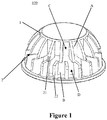
- Fig. 1 is a schematic diagram of the heat dissipation device 100 according to the first embodiment of the present invention.
- the heat dissipation device 100 comprises a base 1 comprising a first section A and a second section B provided in a longitudinal direction, and a heat dissipation structure 2, and the heat dissipation structure 2 comprises a plurality of first fins 21 distributed on a circumferential surface of the first section A and a plurality of second fins 22 distributed on a circumferential surface of the second section B, and an circumferential angular position of the first fin 21 is different from an circumferential angular position of the second fin 22.
- the first fins 21 and the second fins 22 extend in the longitudinal direction of the base 1. However, they are not connected with each other, but are arranged in a staggered manner, which is equivalent to rotating the first section A carrying the first fins 21 at a predetermined angle with respect to the second section B carrying the second fins 22, such that the first fins 21 and the second fins 22 are staggered with respect to each other.
- the first fins 21 extend in the longitudinal direction over the first section A
- the second fins 22 extend in the longitudinal direction over the second section B, and seen in the circumferential direction, the first fins 21 and the second fins 22 do not overlap each other.
- first fins 21 can extend over the first section A and partially enter into the second section B
- second fins 22 can extend over the second section B and partially enter into the first section A, such that the first fins 21 and the second fins 22 partially overlap.
- two adjacent first fins 21 define a first convection region C
- two adjacent second fins 22 define a second convection region D, wherein air from the first convection region C or the second convection region D can be separated by the second fins 22 or the first fins 21.
- the adjacent fins form the regions in which the convectional air flows, the flowing direction of the convectional air flowing over the regions will be changed by the fins that define other convection regions, which thereby effectively reduce the risk of forming a thermal boundary layer on the fins.
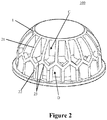
- Fig. 2 is a schematic diagram of the heat dissipation device 100 according to the second embodiment of the present invention.
- the heat dissipation structure 2 further comprises a connection structure such that a flowing channel is defined between the first convection region C and the second convection region D.
- the connection structure partially connects free ends of the first fins 21 in the longitudinal direction with free ends of the second fins 22 in the longitudinal direction.
- connection structure comprises a plurality of connection fins 23, wherein each of the first fins 21 is connected with two adjacent second fins 22 through two connection fins 23. Moreover, the connection fins 23 are connected to a side of the free ends of the first fins 21 and the second fins 22 facing away from the base 1.
- Fig. 3 is a top view of the heat dissipation device 100 shown in Fig. 2 .
- a flowing channel between the first convection region C and the second convection region D is formed in the region in which the first fins 21 and the second fins 22 are connected with each other, and the flowing channel is jointly defined by the first fins 21, the second fins 22, the connection fins 23 and the base 1.
- the first fins 21, the second fins 22 and the connection sheets 23 are made in one piece with the base 1.
- the heat dissipation device 100 can be made of a metal material by a die casting process.
- the heat dissipation device 100 can also be made of a thermal conductive plastic by an injection molding process.
- Fig. 4 is a flow trend diagram of convectional air on the heat dissipation device 100 according to the present invention.
- the convectional air from the outside flows from the bottom of the heat dissipation device 100, viz. the second section B of the heat dissipation device 100, to the first section A.
- the convectional air flows over the surfaces of the second fins 22 in the second convection region D defined by two adjacent second fins 22, after the convectional air flows outside the second convection region D, the first fins 21 and the connection fins 23 disturb the convectional air and changes the flowing direction of the convectional air.
- the convectional air whose flowing direction has been changed subsequently flows into the first convection region C defined by two adjacent first fins 21.
- the risk of forming a thermal boundary layer on the surfaces of the sheet-like fins is reduced, and thereby, the heat dissipation performance of the heat dissipation device 100 is enhanced.
- the illumination apparatus comprising the heat dissipation device 100 according to the present invention is not shown in the figures.
- the illumination apparatus according to the present invention comprises an LED light engine and a driver for driving the LED light engine, the LED light engine and the driver being accommodated in the heat dissipation device 100.
- the illumination apparatus according to the present invention can also employ light sources of other types and the corresponding electrical components.
Landscapes
- Engineering & Computer Science (AREA)
- General Engineering & Computer Science (AREA)
- Arrangement Of Elements, Cooling, Sealing, Or The Like Of Lighting Devices (AREA)
- Cooling Or The Like Of Electrical Apparatus (AREA)
Description
- The present invention relates to a heat dissipation device for an illumination apparatus. In addition, the present invention also relates to an illumination apparatus comprising the heat dissipation device.
- LED retrofit lamps of the types such as MR16, PAR16, PAR20, Classic A and Classic B are seethingly finding the way of replacing other traditional illumination apparatus such as incandescent and fluorescent lamps because they can offer the benefits of energy saving, small size and long lifetime. With the technology development, LED package itself can reach high efficiency, such as 140lm/W for cold white and 90lm/W for warm white and they are supposed to have a long lifetime as to 50,000 hours, but when the LED is integrated into a retrofit lamp together with an LED driver, a thermal management device and an optical component, the efficiency and lifetime of the retrofit lamp are highly dependent upon how to design the driver, heat dissipation device and optical component. Some of the electrical power consumed in the LED converts to heat rather than light. According to statistics of U.S. Department of Energy, 75% to 85% of energy used to drive the LED is converted to heat, and the heat must be conducted from the LED chip to the underlying PCB and heat dissipation device. If the heat cannot be conducted timely, the LED's light output performance will be reduced and a color shift will be produced in the short term, and the lifetime of the LED will be shortened in the long term. And the performance of the heat dissipation device directly affects the LED illumination apparatus. A good heat dissipation device design should be capable of providing favorable local air flow conditions, good radiation between surfaces, low material cost and simpler and easier manufacturing.
- In order to improve heat dissipation performance, most heat dissipation devices are designed to have an increased heat dissipation surface area by using a larger number of fins within the form factor limitation. A large number of sheet-like fins are disposed outside the base of the heat dissipation device, so as to obtain the largest possible contact area with the convectional air. However, the heat dissipation device of this type has an obvious defect, viz. having a relatively larger volume, and reducing air convection among the fins. For this, it is proposed in the prior art to place holes in the fins or design fins with various special shapes, which, however, reduces, to some extent, the contact area of the fins with the convectional air, and reduces the heat dissipation performance of the heat dissipation device. Moreover, the fins of the above type have a complicated structure, are not easy to manufacture, and increase the manufacture complexity and cost of the heat dissipation device.
- In addition, the pure sheet-like heat dissipation device is easier to manufacture, and has a low cost. However, it has a serious defect, viz. when the air flows over the surfaces of the sheet-like fins, a thermal boundary layer is formed on the surface of the fins, which significantly increases the thermal resistance of the heat dissipation device and reduces the heat dissipation performance of the heat dissipation device.
- An earlier patent application
US 2011/204780 A1 discloses a heat dissipation device with a base having an upper section and a lower section. Fins are distributed on a circumferential surface of the lower section, and sub-fins are distributed on a circumferential surface of the upper section. -
US 2011/0080096 A1 andUS 2010/0259942 A1 disclose LED lamps having heat dissipation devices with first and second sections and fins distributed on these sections. - In order to solve the above technical problems, the present invention. provides a heat dissipation. device, which. has a simple structure, is easy to manufacture, has a low cost, can effectively avoid the formation of a thermal boundary layer on the surfaces of the fins of the heat dissipation device, and has a relatively lower thermal resistance and superior heat dissipation performance.
- In addition, the present invention also provides an illumination apparatus comprising such heat dissipation device. The illumination apparatus according to the present invention has a simple appearance, a low cost and superior heat dissipation performance. The first object of the present invention is accomplished via a heat dissipation device for an illumination apparatus, the heat dissipation device comprising: a base comprising a first section and a second section provided in a longitudinal direction, and a heat dissipation structure, and the heat dissipation structure comprises a plurality of first fins distributed on a circumferential surface of the first section and a plurality of second fins distributed on a circumferential surface of the second section, and an circumferential angular position of the first fin is different from an circumferential angular position of the second fin. When the convectional air flows over the surfaces of the sheet-like fins, there will be a trend of forming a thermal boundary layer on the surfaces of the fins, which will reduce the convection effect, reduce the heat exchange capacity, and increase the thermal resistance of the heat dissipation device. In the design solution of the present invention, as the circumferential angular position of the first fin is different from the circumferential angular position of the second fin, viz. the first fins and the second fins are arranged in
a staggered manner, the convectional air deflects when flowing over the surfaces of the first fins and the second fins, which thereby eliminates the possibility of forming a thermal boundary layer on the surfaces of the fins, and improves the heat dissipation performance of the heat dissipation device. - In an embodiment, the first section and the second section are sequentially arranged in the longitudinal direction of the base. In this way, the first fins disposed in the first section and the second fins disposed in the second section are also sequentially arranged in the longitudinal direction of the base, and the first fins and the second fins can be arranged to partially overlap each other or not overlap each other.
- Preferably, the first fins extend in the longitudinal direction over the first section, and the second fins extend in the longitudinal direction over the second section. In this way, the first fins and the second fins are arranged without overlapping each other, and after flowing over the fins in the first section or the second section, the convectional air changes its flowing direction by the fins in the second section or the first section, which thereby effectively reduces the risk of forming a thermal boundary layer on the fins.
- According to the present invention, two adjacent first fins define a first convection region, and two adjacent second fins define a second convection region, wherein air from the first convection region or the second convection region can be separated by the second fins or the first fins. The adjacent fins form the regions in which the convectional air flows, the flowing direction of the convectional air flowing over the regions will be changed by the fins that define other convection regions, which thereby effectively reduce the risk of forming a thermal
boundary layer on the fins. - Further according to the present invention, the heat dissipation structure further comprises a connection structure such that a flowing channel is defined between the first convection region and the second convection region. The connection structure partially connects free ends of the first fins in the longitudinal direction with free ends of the second fins in the longitudinal direction. The connection structure serves the function of connecting and supporting the first fins and the second fins, and improves, to some extent, the overall appearance of the heat dissipation device.
- Further advantageously, the connection structure comprises a plurality of connection fins, wherein each of the first fins is connected with two adjacent second fins through connection fins. These connection fins more or less disturb the convectional air, and thereby further reduce the risk of forming a thermal boundary layer on the fins. In addition, the connection fins further enlarge the contact area between the heat dissipation device and the convectional air, and enhance, to some extent, the heat dissipation performance of the heat dissipation device.
- Preferably, the connection fins are connected to a side of the free ends of the first fins and the second fins facing away from the base. In this way, a channel is formed in the region in which the first fins and the second fins are connected with each other, and the channel is jointly defined by the first fins, the second fins, the connection fins and the base.
- Further advantageously, the first fins, the second fins and the connection structure are made in one piece
with the base, which greatly reduces the manufacture difficulty of the heat dissipation device according to the present invention, and reduces the manufacture cost. - According to a preferred design solution of the present invention, the heat dissipation device is made of a metal material, and is made by a die casting process. Preferably, the heat dissipation device is made of a metal material having high thermal conductive performance, for example, aluminum.
- According to another preferred design solution of the present invention, the heat dissipation device is made of a thermal conductive plastic, and is made by an injection molding process. In addition to the superior thermal conductive performance, the thermal conductive plastic is light and can be molded into various forms according to the design requirements.
- The other object of the present invention is accomplished via an illumination apparatus, comprising the heat dissipation device of the above type. The illumination apparatus according to the present invention has good appearance and superior heat dissipation performance.
- Preferably, the illumination apparatus according to the present invention further comprises an LED light engine and a driver for driving the LED light engine, the LED light engine and the driver being accommodated in the heat dissipation device. LED light engines are widely used in the illumination apparatus as they have the advantages of high luminous efficiency, low power consumption, long lifespan, and so on.
- The drawings constitute a portion of the Description for further understanding of the present invention. These drawings illustrate the embodiments of the present invention and explain the principle of the present invention together with the Description. In the drawings, the same part is represented by the same reference sign. In the drawings,
-
Fig. 1 is a schematic diagram of a heat dissipation device according to the first embodiment of the present invention; -
Fig. 2 is a schematic diagram of the heat dissipation device according to the second embodiment of the present invention; -
Fig. 3 is a top view of the heat dissipation device shown inFig. 2 ; and -
Fig. 4 is a flow trend diagram of convectional air on the heat dissipation device according to the present invention. - In the following detailed Description, reference is made to the accompanying drawings, which form a part hereof, and in which is shown by way of illustration specific embodiments in which the invention may be practiced. In this regard, directional terminology, such as "top", "bottom", "front", "back", "longitudinal direction", "circumferential direction" etc., is used with reference to the orientation of the Figure (s) being described. Because components of embodiments can be positioned in a number of different orientations, the directional terminology is used for purposes of illustration and is in no way limiting. It is to be understood that other embodiments may be utilized and structural or logical changes may be made without departing from the scope of the present invention. The following detailed description, therefore, is not to be taken in a limiting sense, and the scope of the present invention is defined by the appended claims.
-
Fig. 1 is a schematic diagram of theheat dissipation device 100 according to the first embodiment of the present invention. As can be seen from the figure, theheat dissipation device 100 according to the present invention comprises a base 1 comprising a first section A and a second section B provided in a longitudinal direction, and a heat dissipation structure 2, and the heat dissipation structure 2 comprises a plurality offirst fins 21 distributed on a circumferential surface of the first section A and a plurality ofsecond fins 22 distributed on a circumferential surface of the second section B, and an circumferential angular position of thefirst fin 21 is different from an circumferential angular position of thesecond fin 22. As can be seen from the figure, thefirst fins 21 and thesecond fins 22 extend in the longitudinal direction of the base 1. However, they are not connected with each other, but are arranged in a staggered manner, which is equivalent to rotating the first section A carrying thefirst fins 21 at a predetermined angle with respect to the second section B carrying thesecond fins 22, such that thefirst fins 21 and thesecond fins 22 are staggered with respect to each other. In the first embodiment of theheat dissipation device 100 as shown inFig. 1 , thefirst fins 21 extend in the longitudinal direction over the first section A, and thesecond fins 22 extend in the longitudinal direction over the second section B, and seen in the circumferential direction, thefirst fins 21 and thesecond fins 22 do not overlap each other. However, in other embodiments, thefirst fins 21 can extend over the first section A and partially enter into the second section B, and thesecond fins 22 can extend over the second section B and partially enter into the first section A, such that thefirst fins 21 and thesecond fins 22 partially overlap. - In addition, as can be further seen from
Fig. 1 , two adjacentfirst fins 21 define a first convection region C, and two adjacentsecond fins 22 define a second convection region D, wherein air from the first convection region C or the second convection region D can be separated by thesecond fins 22 or thefirst fins 21. The adjacent fins form the regions in which the convectional air flows, the flowing direction of the convectional air flowing over the regions will be changed by the fins that define other convection regions, which thereby effectively reduce the risk of forming a thermal boundary layer on the fins. -
Fig. 2 is a schematic diagram of theheat dissipation device 100 according to the second embodiment of the present invention. As can be seen from the figure, the only difference between theheat dissipation device 100 according to the second embodiment of the present invention and theheat dissipation device 100 according to the first embodiment of the present invention lies in: the heat dissipation structure 2 further comprises a connection structure such that a flowing channel is defined between the first convection region C and the second convection region D. The connection structure partially connects free ends of thefirst fins 21 in the longitudinal direction with free ends of thesecond fins 22 in the longitudinal direction. As can be seen from the figure, the connection structure comprises a plurality ofconnection fins 23, wherein each of thefirst fins 21 is connected with two adjacentsecond fins 22 through twoconnection fins 23. Moreover, theconnection fins 23 are connected to a side of the free ends of thefirst fins 21 and thesecond fins 22 facing away from the base 1. -
Fig. 3 is a top view of theheat dissipation device 100 shown inFig. 2 . As can be seen from the figure, a flowing channel between the first convection region C and the second convection region D is formed in the region in which thefirst fins 21 and thesecond fins 22 are connected with each other, and the flowing channel is jointly defined by thefirst fins 21, thesecond fins 22, theconnection fins 23 and the base 1. - In a preferred design solution of the present invention, the
first fins 21, thesecond fins 22 and theconnection sheets 23 are made in one piece with the base 1. In a preferred embodiment of the present invention, theheat dissipation device 100 can be made of a metal material by a die casting process. In another preferred embodiment of the present invention, theheat dissipation device 100 can also be made of a thermal conductive plastic by an injection molding process. -
Fig. 4 is a flow trend diagram of convectional air on theheat dissipation device 100 according to the present invention. As can be seen from the figure, the convectional air from the outside flows from the bottom of theheat dissipation device 100, viz. the second section B of theheat dissipation device 100, to the first section A. The convectional air flows over the surfaces of thesecond fins 22 in the second convection region D defined by two adjacentsecond fins 22, after the convectional air flows outside the second convection region D, thefirst fins 21 and theconnection fins 23 disturb the convectional air and changes the flowing direction of the convectional air. The convectional air whose flowing direction has been changed subsequently flows into the first convection region C defined by two adjacentfirst fins 21. As the flowing direction of the convectional air has been changed, the risk of forming a thermal boundary layer on the surfaces of the sheet-like fins is reduced, and thereby, the heat dissipation performance of theheat dissipation device 100 is enhanced. - In addition, in order to facilitate observation, the illumination apparatus comprising the
heat dissipation device 100 according to the present invention is not shown in the figures. The illumination apparatus according to the present invention comprises an LED light engine and a driver for driving the LED light engine, the LED light engine and the driver being accommodated in theheat dissipation device 100. Of course, the illumination apparatus according to the present invention can also employ light sources of other types and the corresponding electrical components. - It is to be understood that the features of the various exemplary embodiments described herein may be combined with each other, unless specifically noted otherwise.
- Although specific embodiments have been illustrated and described herein, it will be appreciated by those of ordinary skill in the art that a variety of alternate and/or equivalent implementations may be substituted for the specific embodiments shown and described. This application is intended to cover any adaptations or variations of the specific embodiments discussed herein.
-
- 1
- base
- 2
- heat dissipation structure
- 21
- first fins
- 22
- second fins
- 23
- connection fins
- A
- first section
- B
- second section
- C
- first convection region
- D
- second convection region
- 100
- heat dissipation device
Claims (13)
- A heat dissipation device (100) for an illumination apparatus, comprising: a base (1) comprising a first section (A) and a second section (B) provided in a longitudinal direction, and a heat dissipation structure (2), wherein the heat dissipation structure (2) comprises a plurality of first fins (21) distributed on a circumferential surface of the first section (A) and a plurality of second fins (22) distributed on a circumferential surface of the second section (B), and a circumferential angular position of the first fin (21) is different from a circumferential angular position of the second fin (22),
wherein two adjacent first fins (21) define a first convection region (C), and two adjacent second fins (22) define a second convection region (D), wherein air from the first convection region (C) or the second convection region (D) can be separated by the second fins (22) or the first fins (21), characterized in that the heat dissipation structure (2) further comprises a connection structure such that a flowing channel is defined between the first convection region (C) and the second convection region (D) . - The heat dissipation device (100) according to Claim 1, characterized in that the first section (A) and the second section (B) are sequentially arranged in the longitudinal direction of the base (1).
- The heat dissipation device (100) according to Claim 2, characterized in that the first fins (21) extend in the longitudinal direction over the first section (A), and the second fins (22) extend in the longitudinal direction over the second section (B).
- The heat dissipation device (100) according to Claim 1, characterized in that the connection structure partially connects free ends of the first fins (21) in the longitudinal direction with free ends of the second fins (22) in the longitudinal direction.
- The heat dissipation device (100) according to Claim 4, characterized in that the connection structure comprises a plurality of connection fins (23), wherein each of the first fins (21) is connected with two adjacent second fins (22) through connection fins (23).
- The heat dissipation device (100) according to Claim 5, characterized in that the connection fins (23) are connected to a side of the free ends of the first fins (21) and the second fins (22) facing away from the base (1).
- The heat dissipation device (100) according to Claim 1, characterized in that the first fins (21), the second fins (22) and the connection structure are made in one piece with the base (1).
- The heat dissipation device (100) according to any of Claims 1-3, characterized in that the heat dissipation device (100) is made of a metal material.
- The heat dissipation device (100) according to Claim 8, characterized in that the heat dissipation device (100) is made by a die casting process.
- The heat dissipation device (100) according to any of Claims 1-3, characterized in that the heat dissipation device (100) is made of a thermal conductive plastic.
- The heat dissipation device (100) according to Claim 10, characterized in that the heat dissipation device (100) is made by an injection molding process.
- An illumination apparatus, characterized in that the illumination apparatus comprises a heat dissipation device (100) according to any of Claims 1-11.
- The illumination apparatus according to Claim 12, characterized in that the illumination apparatus further comprises an LED light engine and a driver for driving the LED light engine, the LED light engine and the driver being accommodated in the heat dissipation device (100).
Applications Claiming Priority (2)
| Application Number | Priority Date | Filing Date | Title |
|---|---|---|---|
| CN201210149646.7A CN103423721B (en) | 2012-05-14 | 2012-05-14 | Heat abstractor and the lighting device with the heat abstractor |
| PCT/EP2013/058925 WO2013171062A1 (en) | 2012-05-14 | 2013-04-29 | Heat dissipation device and illumination apparatus comprising the heat dissipation device |
Publications (2)
| Publication Number | Publication Date |
|---|---|
| EP2802813A1 EP2802813A1 (en) | 2014-11-19 |
| EP2802813B1 true EP2802813B1 (en) | 2018-10-31 |
Family
ID=48468224
Family Applications (1)
| Application Number | Title | Priority Date | Filing Date |
|---|---|---|---|
| EP13723690.7A Active EP2802813B1 (en) | 2012-05-14 | 2013-04-29 | Heat dissipation device and illumination apparatus comprising the heat dissipation device |
Country Status (3)
| Country | Link |
|---|---|
| EP (1) | EP2802813B1 (en) |
| CN (1) | CN103423721B (en) |
| WO (1) | WO2013171062A1 (en) |
Families Citing this family (3)
| Publication number | Priority date | Publication date | Assignee | Title |
|---|---|---|---|---|
| CN104654255A (en) * | 2013-11-22 | 2015-05-27 | 苏州承源光电科技有限公司 | Radiator for LEDs |
| CN109340612B (en) * | 2018-09-04 | 2021-01-05 | 东莞市闻誉实业有限公司 | Lighting lamp |
| CN111473300A (en) * | 2020-03-23 | 2020-07-31 | 宁波市富来电子科技有限公司 | Novel automobile L ED tail lamp combination and manufacturing method |
Citations (2)
| Publication number | Priority date | Publication date | Assignee | Title |
|---|---|---|---|---|
| US20100259942A1 (en) * | 2009-01-14 | 2010-10-14 | Yeh-Chiang Technology Corp. | LED lamp |
| US20110080096A1 (en) * | 2009-10-02 | 2011-04-07 | Lumination Llc | Led lamp |
Family Cites Families (5)
| Publication number | Priority date | Publication date | Assignee | Title |
|---|---|---|---|---|
| CN2724201Y (en) * | 2004-07-06 | 2005-09-07 | 陈万添 | radiator structure |
| CN201093431Y (en) * | 2007-08-07 | 2008-07-30 | 东莞市金杲电子贸易有限公司 | LED light fitting |
| CN201310855Y (en) * | 2008-12-10 | 2009-09-16 | 上海三思电子工程有限公司 | Heat-emission lamp holder and LED pixel lamp |
| US8324835B2 (en) * | 2011-02-11 | 2012-12-04 | Soraa, Inc. | Modular LED lamp and manufacturing methods |
| US9335101B2 (en) * | 2011-04-11 | 2016-05-10 | Molex, Llc | LED lamp |
-
2012
- 2012-05-14 CN CN201210149646.7A patent/CN103423721B/en active Active
-
2013
- 2013-04-29 WO PCT/EP2013/058925 patent/WO2013171062A1/en not_active Ceased
- 2013-04-29 EP EP13723690.7A patent/EP2802813B1/en active Active
Patent Citations (2)
| Publication number | Priority date | Publication date | Assignee | Title |
|---|---|---|---|---|
| US20100259942A1 (en) * | 2009-01-14 | 2010-10-14 | Yeh-Chiang Technology Corp. | LED lamp |
| US20110080096A1 (en) * | 2009-10-02 | 2011-04-07 | Lumination Llc | Led lamp |
Also Published As
| Publication number | Publication date |
|---|---|
| WO2013171062A1 (en) | 2013-11-21 |
| CN103423721A (en) | 2013-12-04 |
| EP2802813A1 (en) | 2014-11-19 |
| CN103423721B (en) | 2018-02-13 |
Similar Documents
| Publication | Publication Date | Title |
|---|---|---|
| EP2802813A1 (en) | Heat dissipation device and illumination apparatus comprising the heat dissipation device | |
| CN201764312U (en) | LED bulb and illuminating system | |
| CN101510582B (en) | LED with vertical structure | |
| CN203190364U (en) | Double-channel cross-ventilation lamp radiation structure and PAR lamp using same | |
| WO2011134121A1 (en) | Led light source module | |
| US20120314427A1 (en) | Led heat sink and method for manufacturing the same | |
| CN101571239B (en) | Multi-light emitting surface LED bulb | |
| CN201396602Y (en) | Heat dissipation lamp body and LED lamp composed of it | |
| CN101776227B (en) | LED light assembly and LED street light | |
| TWM345928U (en) | LED lights base made of extruded aluminum | |
| CN103644552A (en) | Air cooling and radiating device of LED lamp | |
| CN205678641U (en) | A kind of LED chiller with stack effect | |
| CN203628587U (en) | Double-radiating structure based on synthetic jet device and radiator | |
| CN201803186U (en) | LED spherical bulb | |
| CN202149404U (en) | Large-power LED (light-emitting diode) projection lamp | |
| CN101709840B (en) | Streetlamp with application-oriented light-emitting diode module | |
| CN207893722U (en) | Radiator | |
| CN203615299U (en) | Air-cooled radiator of LED lamp | |
| CN202195459U (en) | Fin radiator | |
| CN105020685A (en) | LED heat radiation structure | |
| CN201628120U (en) | Multiple radiating LED lamp module | |
| CN203642089U (en) | Novel LED lamp cup | |
| CN203240333U (en) | LED (light-emitting diode) daylight lamp | |
| CN102937280A (en) | Louvered copper aluminum composite phase change high-power radiator | |
| CN202253502U (en) | Tube-guide type heat dissipation device for light emitting diode (LED) lamp |
Legal Events
| Date | Code | Title | Description |
|---|---|---|---|
| PUAI | Public reference made under article 153(3) epc to a published international application that has entered the european phase |
Free format text: ORIGINAL CODE: 0009012 |
|
| 17P | Request for examination filed |
Effective date: 20140812 |
|
| AK | Designated contracting states |
Kind code of ref document: A1 Designated state(s): AL AT BE BG CH CY CZ DE DK EE ES FI FR GB GR HR HU IE IS IT LI LT LU LV MC MK MT NL NO PL PT RO RS SE SI SK SM TR |
|
| DAX | Request for extension of the european patent (deleted) | ||
| 17Q | First examination report despatched |
Effective date: 20160826 |
|
| STAA | Information on the status of an ep patent application or granted ep patent |
Free format text: STATUS: EXAMINATION IS IN PROGRESS |
|
| RAP1 | Party data changed (applicant data changed or rights of an application transferred) |
Owner name: LEDVANCE GMBH |
|
| RIC1 | Information provided on ipc code assigned before grant |
Ipc: F21V 29/83 20150101ALI20180503BHEP Ipc: F21V 29/00 20060101AFI20180503BHEP Ipc: F21V 29/89 20150101ALN20180503BHEP Ipc: F21V 29/75 20150101ALN20180503BHEP Ipc: F21V 29/77 20150101ALI20180503BHEP Ipc: F21V 29/87 20150101ALN20180503BHEP Ipc: F21V 29/50 20150101ALN20180503BHEP |
|
| GRAP | Despatch of communication of intention to grant a patent |
Free format text: ORIGINAL CODE: EPIDOSNIGR1 |
|
| STAA | Information on the status of an ep patent application or granted ep patent |
Free format text: STATUS: GRANT OF PATENT IS INTENDED |
|
| INTG | Intention to grant announced |
Effective date: 20180608 |
|
| GRAS | Grant fee paid |
Free format text: ORIGINAL CODE: EPIDOSNIGR3 |
|
| GRAA | (expected) grant |
Free format text: ORIGINAL CODE: 0009210 |
|
| STAA | Information on the status of an ep patent application or granted ep patent |
Free format text: STATUS: THE PATENT HAS BEEN GRANTED |
|
| AK | Designated contracting states |
Kind code of ref document: B1 Designated state(s): AL AT BE BG CH CY CZ DE DK EE ES FI FR GB GR HR HU IE IS IT LI LT LU LV MC MK MT NL NO PL PT RO RS SE SI SK SM TR |
|
| REG | Reference to a national code |
Ref country code: CH Ref legal event code: EP Ref country code: GB Ref legal event code: FG4D |
|
| REG | Reference to a national code |
Ref country code: AT Ref legal event code: REF Ref document number: 1059836 Country of ref document: AT Kind code of ref document: T Effective date: 20181115 |
|
| REG | Reference to a national code |
Ref country code: DE Ref legal event code: R096 Ref document number: 602013045919 Country of ref document: DE |
|
| REG | Reference to a national code |
Ref country code: IE Ref legal event code: FG4D |
|
| REG | Reference to a national code |
Ref country code: NL Ref legal event code: MP Effective date: 20181031 |
|
| REG | Reference to a national code |
Ref country code: LT Ref legal event code: MG4D |
|
| REG | Reference to a national code |
Ref country code: AT Ref legal event code: MK05 Ref document number: 1059836 Country of ref document: AT Kind code of ref document: T Effective date: 20181031 |
|
| PG25 | Lapsed in a contracting state [announced via postgrant information from national office to epo] |
Ref country code: FI Free format text: LAPSE BECAUSE OF FAILURE TO SUBMIT A TRANSLATION OF THE DESCRIPTION OR TO PAY THE FEE WITHIN THE PRESCRIBED TIME-LIMIT Effective date: 20181031 Ref country code: BG Free format text: LAPSE BECAUSE OF FAILURE TO SUBMIT A TRANSLATION OF THE DESCRIPTION OR TO PAY THE FEE WITHIN THE PRESCRIBED TIME-LIMIT Effective date: 20190131 Ref country code: LT Free format text: LAPSE BECAUSE OF FAILURE TO SUBMIT A TRANSLATION OF THE DESCRIPTION OR TO PAY THE FEE WITHIN THE PRESCRIBED TIME-LIMIT Effective date: 20181031 Ref country code: NO Free format text: LAPSE BECAUSE OF FAILURE TO SUBMIT A TRANSLATION OF THE DESCRIPTION OR TO PAY THE FEE WITHIN THE PRESCRIBED TIME-LIMIT Effective date: 20190131 Ref country code: AT Free format text: LAPSE BECAUSE OF FAILURE TO SUBMIT A TRANSLATION OF THE DESCRIPTION OR TO PAY THE FEE WITHIN THE PRESCRIBED TIME-LIMIT Effective date: 20181031 Ref country code: IS Free format text: LAPSE BECAUSE OF FAILURE TO SUBMIT A TRANSLATION OF THE DESCRIPTION OR TO PAY THE FEE WITHIN THE PRESCRIBED TIME-LIMIT Effective date: 20190228 Ref country code: ES Free format text: LAPSE BECAUSE OF FAILURE TO SUBMIT A TRANSLATION OF THE DESCRIPTION OR TO PAY THE FEE WITHIN THE PRESCRIBED TIME-LIMIT Effective date: 20181031 Ref country code: PL Free format text: LAPSE BECAUSE OF FAILURE TO SUBMIT A TRANSLATION OF THE DESCRIPTION OR TO PAY THE FEE WITHIN THE PRESCRIBED TIME-LIMIT Effective date: 20181031 Ref country code: HR Free format text: LAPSE BECAUSE OF FAILURE TO SUBMIT A TRANSLATION OF THE DESCRIPTION OR TO PAY THE FEE WITHIN THE PRESCRIBED TIME-LIMIT Effective date: 20181031 Ref country code: LV Free format text: LAPSE BECAUSE OF FAILURE TO SUBMIT A TRANSLATION OF THE DESCRIPTION OR TO PAY THE FEE WITHIN THE PRESCRIBED TIME-LIMIT Effective date: 20181031 |
|
| PG25 | Lapsed in a contracting state [announced via postgrant information from national office to epo] |
Ref country code: AL Free format text: LAPSE BECAUSE OF FAILURE TO SUBMIT A TRANSLATION OF THE DESCRIPTION OR TO PAY THE FEE WITHIN THE PRESCRIBED TIME-LIMIT Effective date: 20181031 Ref country code: SE Free format text: LAPSE BECAUSE OF FAILURE TO SUBMIT A TRANSLATION OF THE DESCRIPTION OR TO PAY THE FEE WITHIN THE PRESCRIBED TIME-LIMIT Effective date: 20181031 Ref country code: GR Free format text: LAPSE BECAUSE OF FAILURE TO SUBMIT A TRANSLATION OF THE DESCRIPTION OR TO PAY THE FEE WITHIN THE PRESCRIBED TIME-LIMIT Effective date: 20190201 Ref country code: NL Free format text: LAPSE BECAUSE OF FAILURE TO SUBMIT A TRANSLATION OF THE DESCRIPTION OR TO PAY THE FEE WITHIN THE PRESCRIBED TIME-LIMIT Effective date: 20181031 Ref country code: RS Free format text: LAPSE BECAUSE OF FAILURE TO SUBMIT A TRANSLATION OF THE DESCRIPTION OR TO PAY THE FEE WITHIN THE PRESCRIBED TIME-LIMIT Effective date: 20181031 Ref country code: PT Free format text: LAPSE BECAUSE OF FAILURE TO SUBMIT A TRANSLATION OF THE DESCRIPTION OR TO PAY THE FEE WITHIN THE PRESCRIBED TIME-LIMIT Effective date: 20190301 |
|
| PG25 | Lapsed in a contracting state [announced via postgrant information from national office to epo] |
Ref country code: IT Free format text: LAPSE BECAUSE OF FAILURE TO SUBMIT A TRANSLATION OF THE DESCRIPTION OR TO PAY THE FEE WITHIN THE PRESCRIBED TIME-LIMIT Effective date: 20181031 Ref country code: CZ Free format text: LAPSE BECAUSE OF FAILURE TO SUBMIT A TRANSLATION OF THE DESCRIPTION OR TO PAY THE FEE WITHIN THE PRESCRIBED TIME-LIMIT Effective date: 20181031 Ref country code: DK Free format text: LAPSE BECAUSE OF FAILURE TO SUBMIT A TRANSLATION OF THE DESCRIPTION OR TO PAY THE FEE WITHIN THE PRESCRIBED TIME-LIMIT Effective date: 20181031 |
|
| REG | Reference to a national code |
Ref country code: DE Ref legal event code: R097 Ref document number: 602013045919 Country of ref document: DE |
|
| PG25 | Lapsed in a contracting state [announced via postgrant information from national office to epo] |
Ref country code: SM Free format text: LAPSE BECAUSE OF FAILURE TO SUBMIT A TRANSLATION OF THE DESCRIPTION OR TO PAY THE FEE WITHIN THE PRESCRIBED TIME-LIMIT Effective date: 20181031 Ref country code: EE Free format text: LAPSE BECAUSE OF FAILURE TO SUBMIT A TRANSLATION OF THE DESCRIPTION OR TO PAY THE FEE WITHIN THE PRESCRIBED TIME-LIMIT Effective date: 20181031 Ref country code: RO Free format text: LAPSE BECAUSE OF FAILURE TO SUBMIT A TRANSLATION OF THE DESCRIPTION OR TO PAY THE FEE WITHIN THE PRESCRIBED TIME-LIMIT Effective date: 20181031 Ref country code: SK Free format text: LAPSE BECAUSE OF FAILURE TO SUBMIT A TRANSLATION OF THE DESCRIPTION OR TO PAY THE FEE WITHIN THE PRESCRIBED TIME-LIMIT Effective date: 20181031 |
|
| PLBE | No opposition filed within time limit |
Free format text: ORIGINAL CODE: 0009261 |
|
| STAA | Information on the status of an ep patent application or granted ep patent |
Free format text: STATUS: NO OPPOSITION FILED WITHIN TIME LIMIT |
|
| 26N | No opposition filed |
Effective date: 20190801 |
|
| PG25 | Lapsed in a contracting state [announced via postgrant information from national office to epo] |
Ref country code: SI Free format text: LAPSE BECAUSE OF FAILURE TO SUBMIT A TRANSLATION OF THE DESCRIPTION OR TO PAY THE FEE WITHIN THE PRESCRIBED TIME-LIMIT Effective date: 20181031 |
|
| REG | Reference to a national code |
Ref country code: CH Ref legal event code: PL |
|
| REG | Reference to a national code |
Ref country code: BE Ref legal event code: MM Effective date: 20190430 |
|
| GBPC | Gb: european patent ceased through non-payment of renewal fee |
Effective date: 20190429 |
|
| PG25 | Lapsed in a contracting state [announced via postgrant information from national office to epo] |
Ref country code: MC Free format text: LAPSE BECAUSE OF FAILURE TO SUBMIT A TRANSLATION OF THE DESCRIPTION OR TO PAY THE FEE WITHIN THE PRESCRIBED TIME-LIMIT Effective date: 20181031 Ref country code: LU Free format text: LAPSE BECAUSE OF NON-PAYMENT OF DUE FEES Effective date: 20190429 |
|
| PG25 | Lapsed in a contracting state [announced via postgrant information from national office to epo] |
Ref country code: GB Free format text: LAPSE BECAUSE OF NON-PAYMENT OF DUE FEES Effective date: 20190429 Ref country code: CH Free format text: LAPSE BECAUSE OF NON-PAYMENT OF DUE FEES Effective date: 20190430 Ref country code: LI Free format text: LAPSE BECAUSE OF NON-PAYMENT OF DUE FEES Effective date: 20190430 |
|
| PG25 | Lapsed in a contracting state [announced via postgrant information from national office to epo] |
Ref country code: FR Free format text: LAPSE BECAUSE OF NON-PAYMENT OF DUE FEES Effective date: 20190430 Ref country code: BE Free format text: LAPSE BECAUSE OF NON-PAYMENT OF DUE FEES Effective date: 20190430 |
|
| PG25 | Lapsed in a contracting state [announced via postgrant information from national office to epo] |
Ref country code: TR Free format text: LAPSE BECAUSE OF FAILURE TO SUBMIT A TRANSLATION OF THE DESCRIPTION OR TO PAY THE FEE WITHIN THE PRESCRIBED TIME-LIMIT Effective date: 20181031 |
|
| PG25 | Lapsed in a contracting state [announced via postgrant information from national office to epo] |
Ref country code: IE Free format text: LAPSE BECAUSE OF NON-PAYMENT OF DUE FEES Effective date: 20190429 |
|
| PG25 | Lapsed in a contracting state [announced via postgrant information from national office to epo] |
Ref country code: CY Free format text: LAPSE BECAUSE OF FAILURE TO SUBMIT A TRANSLATION OF THE DESCRIPTION OR TO PAY THE FEE WITHIN THE PRESCRIBED TIME-LIMIT Effective date: 20181031 |
|
| PG25 | Lapsed in a contracting state [announced via postgrant information from national office to epo] |
Ref country code: HU Free format text: LAPSE BECAUSE OF FAILURE TO SUBMIT A TRANSLATION OF THE DESCRIPTION OR TO PAY THE FEE WITHIN THE PRESCRIBED TIME-LIMIT; INVALID AB INITIO Effective date: 20130429 Ref country code: MT Free format text: LAPSE BECAUSE OF FAILURE TO SUBMIT A TRANSLATION OF THE DESCRIPTION OR TO PAY THE FEE WITHIN THE PRESCRIBED TIME-LIMIT Effective date: 20181031 |
|
| PG25 | Lapsed in a contracting state [announced via postgrant information from national office to epo] |
Ref country code: MK Free format text: LAPSE BECAUSE OF FAILURE TO SUBMIT A TRANSLATION OF THE DESCRIPTION OR TO PAY THE FEE WITHIN THE PRESCRIBED TIME-LIMIT Effective date: 20181031 |
|
| PGFP | Annual fee paid to national office [announced via postgrant information from national office to epo] |
Ref country code: DE Payment date: 20260421 Year of fee payment: 14 |