EP2802399B1 - Water purifying filter assembly module and water purifier having the same - Google Patents
Water purifying filter assembly module and water purifier having the same Download PDFInfo
- Publication number
- EP2802399B1 EP2802399B1 EP12863349.2A EP12863349A EP2802399B1 EP 2802399 B1 EP2802399 B1 EP 2802399B1 EP 12863349 A EP12863349 A EP 12863349A EP 2802399 B1 EP2802399 B1 EP 2802399B1
- Authority
- EP
- European Patent Office
- Prior art keywords
- water
- water purifying
- unit
- filter
- head unit
- Prior art date
- Legal status (The legal status is an assumption and is not a legal conclusion. Google has not performed a legal analysis and makes no representation as to the accuracy of the status listed.)
- Active
Links
Images



Classifications
-
- B—PERFORMING OPERATIONS; TRANSPORTING
- B01—PHYSICAL OR CHEMICAL PROCESSES OR APPARATUS IN GENERAL
- B01D—SEPARATION
- B01D35/00—Filtering devices having features not specifically covered by groups B01D24/00 - B01D33/00, or for applications not specifically covered by groups B01D24/00 - B01D33/00; Auxiliary devices for filtration; Filter housing constructions
- B01D35/30—Filter housing constructions
-
- B—PERFORMING OPERATIONS; TRANSPORTING
- B01—PHYSICAL OR CHEMICAL PROCESSES OR APPARATUS IN GENERAL
- B01D—SEPARATION
- B01D35/00—Filtering devices having features not specifically covered by groups B01D24/00 - B01D33/00, or for applications not specifically covered by groups B01D24/00 - B01D33/00; Auxiliary devices for filtration; Filter housing constructions
- B01D35/30—Filter housing constructions
- B01D35/301—Constructions of two or more housings
- B01D35/303—Constructions of two or more housings the housings being modular, e.g. standardised
-
- B—PERFORMING OPERATIONS; TRANSPORTING
- B01—PHYSICAL OR CHEMICAL PROCESSES OR APPARATUS IN GENERAL
- B01D—SEPARATION
- B01D25/00—Filters formed by clamping together several filtering elements or parts of such elements
- B01D25/02—Filters formed by clamping together several filtering elements or parts of such elements in which the elements are pre-formed independent filtering units, e.g. modular systems
-
- B—PERFORMING OPERATIONS; TRANSPORTING
- B01—PHYSICAL OR CHEMICAL PROCESSES OR APPARATUS IN GENERAL
- B01D—SEPARATION
- B01D35/00—Filtering devices having features not specifically covered by groups B01D24/00 - B01D33/00, or for applications not specifically covered by groups B01D24/00 - B01D33/00; Auxiliary devices for filtration; Filter housing constructions
-
- C—CHEMISTRY; METALLURGY
- C02—TREATMENT OF WATER, WASTE WATER, SEWAGE, OR SLUDGE
- C02F—TREATMENT OF WATER, WASTE WATER, SEWAGE, OR SLUDGE
- C02F1/00—Treatment of water, waste water, or sewage
- C02F1/001—Processes for the treatment of water whereby the filtration technique is of importance
-
- B—PERFORMING OPERATIONS; TRANSPORTING
- B01—PHYSICAL OR CHEMICAL PROCESSES OR APPARATUS IN GENERAL
- B01D—SEPARATION
- B01D2201/00—Details relating to filtering apparatus
- B01D2201/30—Filter housing constructions
- B01D2201/301—Details of removable closures, lids, caps, filter heads
- B01D2201/302—Details of removable closures, lids, caps, filter heads having inlet or outlet ports
-
- C—CHEMISTRY; METALLURGY
- C02—TREATMENT OF WATER, WASTE WATER, SEWAGE, OR SLUDGE
- C02F—TREATMENT OF WATER, WASTE WATER, SEWAGE, OR SLUDGE
- C02F2201/00—Apparatus for treatment of water, waste water or sewage
- C02F2201/002—Construction details of the apparatus
- C02F2201/006—Cartridges
-
- C—CHEMISTRY; METALLURGY
- C02—TREATMENT OF WATER, WASTE WATER, SEWAGE, OR SLUDGE
- C02F—TREATMENT OF WATER, WASTE WATER, SEWAGE, OR SLUDGE
- C02F2201/00—Apparatus for treatment of water, waste water or sewage
- C02F2201/002—Construction details of the apparatus
- C02F2201/007—Modular design
Definitions
- the present invention relates to a water purifying filter assembly module in which one or more water purifying filters are connected or separated, and in the case that the water purifying filters are connected, raw water is introduced to the water purifying filters and purified water filtered by the water purifying filters flows out therefrom, and a water purifier having the same, and more particularly, to a water purifying filter assembly module in which when a filtering unit in which one or more water purifying filters are connected to a head unit is installed in and connected to a case unit, raw water is introduced to the filtering unit without a pipe connection operation, and purified water filtered by the filtering unit flows out therefrom, and a water purifier having the same.
- a water purifying filter assembly module is a device installed in a water purifier, or the like, in which one or more water purifying filters are connected, raw water is introduced to the water purifying filters, and purified water filtered by the water purifying filters flows to the outside, e.g., to a purified water tank storing purified water.
- a related art water purifying filter assembly module is provided in a water purifier, or the like, and includes a head unit having one or more water purifying filters connected thereto or separated therefrom, supplies raw water to the connected water purifying filters, and allows purified water filtered by the water purifying filters to flow out therefrom to the outside.
- water may be leaked from the head unit or the water purifying filter, and in this case, since water is leaked to the water purifier equipped with the head unit, or the like, electronic equipment may suffer a failure, or the water purifier may be contaminated.
- the two or more water purifying filters cannot be connected in series. Namely, in the case of connecting two or more water purifying filters to the related art water purifying filter assembly module, two or more water purifying filters are connected to the water purifying filter assembly module in parallel.
- water may be simultaneously introduced to the two or more water purifying filters, and water filtered by the two or more water purifying filters simultaneously flows out therefrom.
- two or more different types of water purifying filter cannot be connected to the water purifying filter assembly module, and since only the same type of water purifying filter can be used, water filtering efficiency based on water purifying filters may be degraded.
- the two or more water purifying filters should be replaced together. Namely, if only some of the same type of water filters, among two or more water purifying filters, are replaced, water filtration efficiency is degraded by the unreplaced water purifying filter.
- WO 2008/035830 A1 describes a filter cartridge and a filter head including: a filter housing having an inlet port through which unfiltered water is introduced, an outlet port through which water filtered by a filtering member is drained, and a filtering member; a cap member engaged with the filter housing, forming a chamber region where unfiltered water is temporarily stored, and having an inlet formed in an outer direction through which unfiltered water is introduced and a sleeve formed in an inner direction at a center portion; and a check valve disposed in the chamber region, and which blocks water flow from the inlet toward the filter housing before the filter housing is engaged and allows water flow toward the filter housing when the filter housing is engaged.
- the filter housing is engaged with the cap member by rotating the filter housing.
- US 2005/178708 A1 describes an automatic water filtration and purification system to allow a continuous water flow to downstream fixtures while simultaneously and automatically regularly flushing and cleaning in-path filter media.
- the automatic water filtration and purification system has at least one filter to remove impurities from a water in-path through-put.
- a cleaner is coupled to the at least one filter to clean the at least one filter.
- a controller is coupled to the at least one filter to regulate automatic operation of the cleaner wherein continuous operation of water flow to fixtures downstream of the at least one filter is essentially uninterrupted during the operation of the cleaner and the controller.
- a filter assembly for a water supply device comprises: a filter member including a cylindrical filter filtering raw water, and a front holder and a rear holder installed on both sides of the cylindrical filter; a filter case including a body having an opening formed in one side thereof to house the filter member in the opening, a cap opening or closing the opening of the body, tubular inlet and outlet projected to the outside from the body, a protrusion part formed to a predetermined size on a side end of the body, and a handle formed on a top part of the body; a filter case housing into which the inlet and outlet of the filter case are inserted, which has tubular inflow part and outflow part formed on the outer side thereof such that a supply pipe and a water supply pipe are connected to the inflow part and outflow part, and which has a hook part formed on an inner side thereof such that the hook part is
- KR 2010 0051447 A describes a clean water filter assembly comprising the following: an assembly head comprised of a water inlet, a water exit and a connector; a water purification filter housing which is connected or detached to the connector; a purified water inlet part; a UV lamp ultraviolet-sterilizing water which is filtered and flowed; a purified water outlet part discharging water sterilized by ultraviolet ray; a UV filter mounted to the assembly head.
- the UV filter includes the following: a constant-rate valve connected to a purified water inlet part; a constant-rate flow feed part in which a constant-rate flow outlet part is connected to a constant-rate valve; a constant-rate flow inlet part connected to the constant-rate flow outlet part; and a UV filter housing with the UV lamp, a purified water outlet.
- the constant-rate flow feed part includes a flow sensor.
- EP 2 206 543 A1 describes a water purifying system having a bypass path supplying raw water to an outlet when a filter assembly is separated from a valve assembly.
- the water purifying system includes a valve assembly having a valve cover with an inlet and an outlet, and a head member moved up and down within the valve cover to form an inflow path and an outflow path, and a filter assembly removably connected to the valve assembly and mounted with a filter.
- the filter assembly advances the head member so that a fluid flown in through the inlet is guided to the outlet passing through the filter.
- the head member is retreated so that the fluid flown through the inlet is guided to the outlet bypassing the filter.
- KR 2010 0050335 A describes a water purifying filter assembly including the following: a filter housing with a connection part and a falling prevention member and is built inside the water purifying filter; an inlet and an outlet connected to the water purifying filter; and an assembly head with a separation part separating the filter housing.
- a falling prevention protrusion is equipped to the separation part.
- a rotation restricting part is formed on the falling prevention member.
- US 2008/047900 A1 describes a filter, comprising: a housing defining an inner cavity; an inner sleeve disposed within the housing, the inner sleeve having portions in a spaced relationship with respect to the an interior surface of the inner cavity; a plurality of tab members extending away from the inner sleeve, the tab members being configured to be removably secured to a feature of a cap, the cap being configured to engage the housing to provide a first position and a second position with respect to the housing, wherein the first position seals the inner sleeve to the housing and a fluid filtration path from an inlet of the filter to an outlet of the filter is defined by the inner sleeve and the second position provides a fluid drain path through an opening in the cap, the fluid drain path being closed when the cap is in the first position; and a filtration media disposed within an interior area of the inner sleeve, wherein the filtration media is disposed in the fluid filtration path and fluid flow through the outlet opening must pass through
- JP H04 102694 U describes a water purification apparatus having a body part provided with a raw water supply part and a drain part and a plurality of water purification cartridges mounted on the body part, and these water purification cartridges are provided in the body part.
- the water purifier is detachably mounted on a plurality of parts to be mounted and is provided with identification means for preventing erroneous attachment of each of the water purification cartridges to the mounted parts.
- the present invention has been devised through recognition of any one of the issues or problems evident in the related art.
- An aspect of the present invention provides a water purifying filter assembly module in which when a filtering unit in which one or more water purifying filters are connected to a head unit is installed in and connected to a case unit, raw water is introduced to the filtering unit without a pipe connection operation, and purified water filtered by the filtering unit flows out therefrom, and a water purifier having the same.
- An aspect of the present invention also provides a water purifying filter assembly module in which a filtering unit in which water purifying filters are connected to a head unit is connected to a case unit or separated therefrom such that it is easily installed therein.
- An aspect of the present invention also provides a water purifying filter assembly module in which a water purifying filter may be replaced, even in a narrow space.
- An aspect of the present invention also provides a water purifying filter assembly module in which when a filtering unit in which water purifying filters are connected to a head unit is separated from a case unit, raw water is prevented from flowing into the water purifying filters.
- An aspect of the present invention also provides a water purifying filter assembly module in which when a filter unit including water purifying filters connected to a head unit is separated, water is allowed to be leaked to a case unit to thus prevent contamination or an incident due to leaking water.
- a water purifying filter assembly module and a water purifier having the same in relation to an embodiment for realizing at least one of the tasks may have the following features.
- the present invention is largely based on a technique in which when a filtering unit in which one or more water purifying filters are connected to a head unit is connected to a case unit so as to be installed therein, raw water is introduced to the filtering unit without a pipe connection operation, and purified water filtered by the filtering unit flows out therefrom.
- a water purifying filter assembly module including: a head unit, to or from which one or more water purifying filters are connected or separated, allowing raw water to flow into the water purifying filters and purified water filtered by the water purifying filters to flow out therefrom, when the water purifying filters are connected to the head unit; and a case unit, to or from which a filtering unit in which the water purifying filters are connected to the head unit is connected or separated so as to be installed therein, allowing raw water to flow into the head unit and purified water from the head unit to flow out therefrom, when the filtering unit is connected to the case unit.
- the filtering unit when the filtering unit is separated from the case unit, the filtering unit may be lifted upwardly from the case unit.
- the head unit includes: a head unit main body; a filter connection part disposed in the head unit main body to allow raw water to flow into the water purifying filters and purified water filtered by the water purifying filters to flow out therefrom, when the water purifying filters are connected; and a detaching part disposed in the head unit main body to facilitate a connection to or separation from the case unit.
- One detaching part may be disposed on either side of the head unit main body.
- the detaching part may include a detaching member elastically supported by the head unit main body in order to connect the filtering unit to the case unit or separate the filtering unit therefrom.
- the detaching part may include: an elastic member inserted into an insertion projection formed on a head unit main body; and a detaching member elastically supported by the elastic member and configured to be caught by the case unit when connected to the case unit and released from the case unit when separated from the case unit.
- a handle portion may be formed on one side of the detaching member such that the handle portion is inserted into and protruded from a handle hole formed in the head unit main body
- a stopping projection may be formed on the other side of the detaching member such that the stopping projection is inserted into and protruded from an insertion hole formed in the head unit main body and caught by a stopping hole formed in the case unit when connected to the case unit.
- the head unit further includes: an inlet/outlet part disposed in the head unit main body and allowing raw water introduced to the case unit to flow into the filter connection part and purified water flowing out from the filter connection unit to flow out therefrom through the case unit, when connected to the case unit.
- the inlet/outlet part includes: a raw water inlet having one side disposed in the head unit main body so as to be connected to an inlet connection portion included in the filter connection part and the other side inserted into an inlet insertion part disposed in the case unit, when connected to the case unit; and a purified water outlet having one side disposed in the head unit main body so as to be connected to an outlet connection portion included in the filter connection part and the other side inserted into an outlet insertion part provided in the case unit, when connected to the case unit.
- the filter connection part includes: an inlet connection portion connected to an inlet disposed in the water purifying filter when the water purifying filter is connected; and an outlet connection portion connected to an outlet disposed in the water purifying filter when the water purifying filter is connected.
- the case unit includes the inlet insertion part connected to a raw water source, the raw water inlet portion included in the head unit being inserted thereinto when the filtering unit is connected; and the outlet insertion part, into which the purified water outlet included in the head unit is inserted, when the filtering unit is connected.
- the inlet insertion part includes an opening and closing member opening a flow channel formed in the inlet insertion part when the raw water inlet is inserted therein and closing the flow channel when the raw water inlet is separated.
- the opening and closing member may be elastically supported by an elastic member provided in the inlet insertion part.
- the stopping hole may be formed in an upper portion of the case unit to allow a stopping projection formed in the detaching member included in the head unit to be caught therein when the filtering unit is connected.
- a water purifier including: a water purifier housing; and the foregoing water purifying filter assembly module installed in the water purifier housing, wherein the head unit included in the water purifying filter assembly module may be exposed from an upper surface of the water purifier housing or may be exposed to the outside when a top cover of the water purifier housing is separated.
- the filtering unit in which one or more water purifying filters are connected to the head unit is connected to the case unit such that it is installed in the case unit, raw water can flow into the filtering unit without a pipe connection operation and purified water filtered by the water purifying filters can flow out therefrom.
- the filtering unit in which water purifying filters are connected to a head unit can be connected to a case unit such that it is easily installed therein or separated therefrom.
- the filtering unit is completely lifted upwardly by separating it from the case unit and the water purifying filter is separated from the head unit, the water purifying filter can be replaced even in a narrow space.
- the elastically supported opening and closing member closes the opening and closing member to prevent raw water from flowing into the water purifying filters.
- the filtering unit in which the water purifying filters are connected to the head unit is separated from the case unit, although water is leaked, it is leaked to the case unit, thus preventing contamination of the interior of the water purifier or an electric incident, or the like, due to the dripping water.
- two or more different types of water purifying filters may be connected in series.
- two or more water purifying filters may not be replaced together.
- water filtering efficiency by the water purifying filters can be enhanced.
- two or more water purifying filters can be connected to appropriate filter connection parts, respectively, among two or more filter connection parts included in the head unit to allow the water purifying filters to be connected thereto.
- Embodiments in relation to the present invention are based on a concept that when a filtering unit in which one or more water purifying filters are connected to a head unit is installed in and connected to a case unit, raw water is introduced to the filtering unit without a pipe connection operation, and purified water filtered by the filtering unit flows out therefrom.
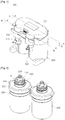
- a water purifying filter assembly module 100 includes a head unit 300 to or from which one or more water purifying filters 200 are connected or separated and a case unit 500 to or from which a filtering unit 400 including the water purifying filters 200 connected to the head unit 300 is connected so as to be installed therein or separated.
- the water purifying filter 200 has an inlet 210 through which raw water or purified water filtered by a different water purifying filter 200 flows.
- the water purifying filter 200 may have a filtering member 230 filtering raw water introduced through the foregoing inlet 210 or purified water introduced after being filtered by the different water purifying filter 200.
- the water purifying filter 200 may have an outlet 220 allowing filtered purified water to flow out therethrough.
- the water purifying filter 200 may have a connection protuberance 240 formed thereon.
- the connection protuberance 240 of the water purifying filter 200 may be caught by a stopping projection (not shown) formed on a filter connection part 320 (to be described) included in the head unit 300 or released therefrom according to rotation of the water purifying filter 200.
- the water purifying filter 200 may be connected to the head unit 300, specifically, to the filter connection part 320 of the head unit 300 in the illustrated embodiment, through rotation, as illustrated in FIGS. 5 and 7 , or may be separated therefrom as illustrated in FIG. 8 .
- the water purifying filter 200 may have a rotation preventing projection 260.
- a rotation preventing recess 530 may be formed in a filter insertion part 500b formed to allow the water purifying filter 200 to be inserted into the case unit 500 (to be described).
- the rotation preventing projection 260 of the water purifying filter 200 may be inserted into the rotation preventing recess 530 of the filter insertion part 500b of the case unit 500. Accordingly, the water purifying filter 200 inserted in the filter insertion part 500b may not be rotated. Thus, the water purifying filter 200 inserted in the filter insertion part is prevented, for example, from being rotated by pressure of water introduced into the water purifying filter 200 and separated from the filter connection part 320.
- the water purifying filter 200 has an identification projection 250. Also, as shown in the illustrated embodiment, the identification projection 250 is not formed on the different water purifying filter 200.
- a different identification projection 350 is formed on the filter connection part (to be described) included in the head unit 300, to which the water purifying filter 200 with the identification projection 250 formed thereon is not to be connected. Also, the different identification projection 350 is not formed on a filter connection part 320 to which the water purifying filter 200 is to be connected.
- the identification projection 250 formed on the water purifying filter 200 may be interfered with by the identification projection 350 formed on the filter connection part 320, and thus, the water purifying filter 200 is not connected to the filter connection part 320 to which the water purifying filter 200 should not be connected, and is only connected to the filter connection part 320 to which the water purifying filter 200 should be connected.
- two or more water purifying filters 200 are connected to appropriate filter connection parts 320, respectively, among the two or more filter connection parts 320 included in the head unit 300 to allow the water purifying filters 200 to be connected thereto.
- one or more water purifying filters 200 may be connected to the head unit 300 or separated therefrom. As shown in the illustrated the embodiment, two water purifying filters 200 may be connected to or separated from the head unit 300. However, the number of water purifying filters 200 connected to or separated from the head unit 300 is not limited thereto and any number of water purifying filters 200 may be connected to or separated from the head unit 300 as long as it is one or more.
- the head unit 300 is configured to allow raw water to be introduced to the water purifying filter 200 and purified water filtered by the water purifying filter 200 to flow out therefrom, when the water purifying filter 200 is connected to the head unit 300.
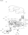
- the head unit 300 includes a head unit main body 310, the filter connection part 320, and a detaching part 330.
- the head unit main body 310 may include a cover member 310a and a main body member 310b.
- the head unit main body 310 may be configured by connecting the cover member 310a to an opened upper portion of the main body member 310b.
- the cover member 310a includes an insertion projection 311, and the main body member 310b may include an insertion recess 312.
- the foregoing insertion projection 311 may be inserted into the insertion recess 312.
- the configuration in which the cover member 310a is connected to the opened upper portion of the main body member 310b to form the head unit main body 310 is not limited thereto, and any known configuration may be employed as long as the cover member 310a is connected to the opened upper portion of the main body member 310b to form the head unit main body 310.
- the filter connection part 320 may be disposed in the head unit main body 310, i.e., specifically, in the main body member 310b of the head unit main body 310 in the illustrated embodiment, to allow raw water to be introduced to the water purifying filter 200 and purified water filtered by the water purifying filter 200 to flow out therefrom, when the water purifying filter 200 is connected thereto.
- two filter connection parts 320 may be included in the head unit 300. Accordingly, two water purifying filters 200 may be connected to or separated from the head unit 300.
- the number of the filter connection parts 320 included in the head unit 300 is not limited thereto and one filter connection part or three or more filter connection parts may be included in the head unit 300.
- one filter connection part 320 is included in the head unit 300, only one water purifying filter 200 may be connected to or separated from the head unit 300.
- three or more filter connection parts 320 are included in the head unit 300, three or more water purifying filters 200 may be connected to or separated from the head unit 300.
- the filter connection part 320 includes an inlet connection portion 321 and an outlet connection portion 322.
- the inlet connection portion 321 may be connected to the inlet 210 provided in the water purifying filter 200 when the water purifying filter 200 is connected.
- raw water introduced to the inlet connection portion 321 may flow to the inlet 210 of the water purifying filter 200.
- the outlet connection portion 322 may be connected to the outlet 220 provided in the water purifying filter 200.
- raw water introduced to the water purifying filter 200 through the inlet connection portion 321 and the inlet 210 of the water purifying filter 200 is filtered by the filtering member 230 provided in the water purifying filter 200, while passing therethrough, and subsequently flows out therefrom through the outlet 220 of the water purifying filter 200 and the outlet connection portion 322.
- two filter connection parts 320 may be provided in the head unit main body 310, specifically, in the main body members 310b of the head unit main body 310.
- the two filter connection parts 320 may be connected by a connection pipe T.
- one side and the other side of the connection pipe T may be connected to the two filter connection parts 320 by a fitting member F, respectively.
- connection pipe T may be connected to the outlet connection portion 322 of the filter connection part 320, and the other side of the connection pipe T may be connected to the inlet connection portion 321 of the other filter connection part 320. Accordingly, as illustrated in FIG. 5 , purified water filtered by one water purifying filter 200 may flow out therefrom from the outlet connection portion 322 of the one filter connection part 320 connected thereto, flows through the connection pipe T, and subsequently flows into the inlet connection portion 321 of the other filter connection part 320, thus being introduced to the other water purifying filter 200.
- two or more types of water purifying filters 200 may be connected in series by connecting them to the head unit 300.
- water filtering efficiency by the water purifying filters 200 can be enhanced.
- the water purifying filters 200 connected to the head unit 300 may not necessarily be replaced together.
- one or more sealing members R may be disposed in the inlet 210 and the outlet 220 of the water purifying filter 200. Accordingly, as described above and as illustrated in FIG. 5 , since the inlet 210 and the outlet 220 are connected to the inlet connection portion 321 and the outlet connection portion 322 of the filter connection part 320, respectively, when raw water or purified water flows, it is not leaked to the outside.
- the detaching part 330 may be disposed in the head unit main body 310, i.e., in the main body member 310b of the head unit main body 310 in the embodiment illustrated in FIG. 3 .
- the filtering unit 400 in which the water purifying filter 200 is connected to the head unit 300 may be easily connected to the case unit 500 as illustrated in FIG. 5 or may be easily separated from the case unit 500 as illustrated in FIG. 7 .
- two detaching parts 330 may be provided in both sides of the head unit main body 310, i.e., in both sides of the main body member 310b of the head unit main body 310 in the illustrated embodiment.
- the number of the detaching parts 330 is not limited thereto and any number of detaching parts may be provided as long as the filtering unit 400 in which the water purifying filter 200 is connected to the head unit 300 is easily connected to the case unit 500 or easily separated from the case unit 500.
- the detaching part 330 may include a detaching member 332 elastically supported in the head unit main body 310 in order to connect the filtering unit 400 to the case unit 500 or separate the filtering unit 400 from the case unit 500.
- the detaching part 330 may include an elastic member 331 and the foregoing detaching member 332.
- the elastic member 331 may be inserted into the head unit main body 310, specifically, into an insertion projection 310c provided in the main body member 310b of the head unit main body 310.
- the detaching member 332 may be elastically supported by the foregoing elastic member 331. Also, the detaching member 332 may configured to allow the filtering unit 400 in which the water purifying filter 200 is connected to the head unit 300 to be caught in the case unit 500 when the filtering unit 400 is connected to the case unit 500 as illustrated in FIG. 5 , and allow the filtering unit 400 to be released from the case unit 500 when the filtering unit 400 is separated from the case unit 500 as illustrated in FIG. 7 . Accordingly, as mentioned above, the filtering unit 400 may be easily connected to the case unit 500 or easily separated from the case unit 500.
- a handle portion 332a may be formed on one side of the detaching member 332, and a stopping projection 332b may be formed on the other side of the detaching member 332.
- the handle portion 332a may be inserted into the head unit main body 310, specifically into a handle hole 310d formed in the main body member 310b of the head unit main body 310, so as to be protruded.
- the handle portion 332a may have a plurality of abrasive projections or a plurality of abrasive recesses formed thereon as illustrated.
- the stopping projection 332b may be inserted into an insertion hole 310e formed on the head unit main body 310, specifically on the main body member 310b of the head unit main body 310 in the illustrated embodiment, so as to be protruded. Also, the stopping projection 332b may be caught in a stopping hole 500a formed in the case unit 500 when the filtering unit 400 in which the water purifying filter 200 is connected to the head unit 300 is connected to the case unit 500, as illustrated in FIG. 6 .
- the detaching member 332 when the user applies external force by pressing the handle portion 332a of the detaching member 332, the detaching member 332, overcoming elastic force of the elastic member 331, may move inwardly of the head unit main body 310, specifically, the main body member 310b of the head unit main body 310.
- the filtering unit 400 in which the water purifying filter 200 is connected to the head unit 300 is insertedly installed in the case unit 500.
- the detaching member 332 is moved to an outer side of the head unit main body 310, specifically, the main body member 310b of the head unit main body 310 in the illustrated embodiment, so as to be returned to its original position.
- the stopping projection 332b of the detaching member 332 may be caught in the stopping hole 500a formed in the case unit 500 as illustrated in FIG. 6 .
- the filtering unit 400 in which the water purifying filter 200 is connected to the head unit 300 is insertedly installed in the case unit 500 such that it is not separated from the case unit 500 as illustrated.
- the detaching member 332 overcoming elastic force of the elastic member 331, is moved inwardly of the head unit main body 310, specifically, inwardly of the main body member 310b of the head unit main body 310 in the illustrated embodiment. Accordingly, the stopping projection 332b of the detaching member 332 is released from the stopping hole 500a of the case unit 500. Accordingly, as illustrated in FIG. 7 , the filtering unit 400 insertedly positioned in the case unit 500 can be easily separated from the case unit 500.
- the detaching member 332 is returned to its original position by elastic force of the elastic member 331.
- the filtering unit 400 in which the water purifying filter 200 is connected to the head unit 300 may be connected to and separated from the case unit 500 such that it is easily installed therein.
- the water purifying filter 200 may be rotated to be separated from the head unit 300 as illustrated in FIG. 8 .
- the filtering unit 400 in which the water purifying filter 200 is connected to the head unit 300 may be connected to the case unit 500 such that it is installed in the case unit 500.
- the case unit 500 to which the filtering unit 400 in which the water purifying filter 200 is connected to the head unit 300 is connected may be provided to a water purifier, or the like.
- the filtering unit 400 in which the water purifying filter 200 is connected to the head unit 300 is separated from the case unit 500, the water purifying filter 200 may be replaced, and the filtering unit 400 in which the water purifying filter 200 is connected to the head unit 300 may be connected to the case unit 500.
- the filtering unit 400 when the filtering unit 400 is separated from the case unit 500, it may be lifted upwardly of the case unit 500.
- the water purifying filter 200 is not connected to the head unit 300 or separated from the head unit 300 with the head unit 300 connected to a water purifier (not shown) as in the related art, the water purifying filter 200 may be replaced even in a narrow space.
- the head unit 300 further includes an inlet/outlet part 340.
- the inlet/outlet part 340 may be provided in the head unit main body 310, specifically, in the main body member 310b of the head unit main body 310 in the illustrated embodiment.
- the inlet/outlet part 340 is configured to allow raw water introduced to the case unit 500 to flow into the filter connection part 320 and purified water flowing out of the filter connection part 320 to flow out therefrom through the case unit 500, when the filtering unit 400 in which the water purifying filter 200 is connected to the head unit 300 is connected to the case unit 500.
- the inlet/outlet part 340 includes a raw water inlet 341 and a purified water outlet 342.
- one side of the raw water inlet 341 may be disposed on the head unit main body 310, specifically, on the main body member 310b in the illustrated embodiment, so as to be connected to the inlet connection portion 321 of the foregoing filter connection part 320 as illustrated in FIG. 6 .
- One side of the raw water inlet 341 may be connected to the other side of the connection pipe T having one side connected to the inlet connection portion 321 of the filter connection part 320 so as to be connected to the inlet connection portion 321 of the filter connection part 320 as in the illustrated embodiment.
- One side and the other side of the connection pipe T may be connected to one side of the inlet connection portion 321 of the filter connection part 320 and one side of the raw water inlet 341 by the fitting member F.
- the filtering unit 400 in which the water purifying filter 200 is connected to the head unit 300 is connected to the case unit 500, the other side of the raw inlet 341 is inserted to be connected to an inlet insertion part 510 (to be described) provided in the case unit 500 and connected to a raw water source (not shown) such as tap water, or the like.
- the raw water introduced to the inlet insertion portion 510 may be introduced to the raw water inlet 341.
- the raw water introduced to the raw water inlet 341 may flow to the inlet connection portion 321 of the foregoing filter connection part 320.
- the raw water flowing to the inlet connection portion 321 of the filter connection part 320 may be introduced to the water purifying filter 200 through the inlet 210 of the water purifying filter 200 connected to the inlet connection portion 321 of the filter connection part 320.
- one side of the purified water outlet 342 may be provided in the head unit main body 310, specifically, in the main body member 310b of the head unit main body 310, so as to be connected to the outlet connection portion 322 of the foregoing filter connection part 320.
- one side of the purified water outlet 342 may be connected to the other side of the connection pipe T having one side connected to the outlet connection portion 322 of the filter connection part 320, so as to be connected to the outlet connection portion 322 of the filter connection part 320.
- one side and the other side of the connection pipe T may be connected to one side of the outlet connection portion 322 of the filter connection part 320 and one side of the purified water outlet 342 by the fitting member F.
- the other side of the purified water outlet 342 may be inserted in and connected to the outlet insertion part 520 provided in the case unit 500. Accordingly, purified water flowing out of the outlet 220 of the water purifying filter 200 after being filtered by the water purifying filter 200 may be introduced to the purified water outlet 342 through the outlet connection portion 322 of the filter connection part 320. The water introduced to the purified water outlet 342 may be introduced to the outlet insertion part 520 so as to flow out therefrom to the outside.
- one or more sealing members R may be provided on the other side of the raw water inlet 341 and the purified water outlet 342. Accordingly, as mentioned above, when the filtering unit 400 in which the water purifying filter 200 is connected to the head unit 300 is connected to the case unit 500 and raw water is introduced to the raw water inlet 341 through the inlet insertion part 510 of the case unit 500, the raw water may not be leaked to the outside. Also, as mentioned above, when purified water flowing out of the purified water outlet 342 flows to the outlet insertion part 520 of the case unit 500, it may not be leaked to the outside.
- the filtering unit 400 in which the water purifying filter 200 is connected to the head unit 300 may be connected to the case unit 500 such that it is installed therein or separated therefrom.
- the case unit 500 may be configured to allow raw water to be introduced to the head unit 300 and purified water flowing out of the head unit 300 to flow out therefrom, when the filtering unit 400 is connected.
- the case unit 500 includes the inlet insertion part 510 and the outlet insertion part 520.
- the inlet insertion part 510 is connected to, for example, a raw water source (not shown) such as tap water, or the like. Also, as illustrated in FIG. 6 , when the filtering unit 400 is connected to the case unit 500, the foregoing raw water inlet 341 included in the head unit 300 is inserted to be connected. Accordingly, as described above and as illustrated in FIG. 6 , raw water from the raw water source is introduced to the head unit 300, i.e., the inlet connection portion 321 of the filter connection part 320 of the head unit, through the inlet insertion part 510 and the raw water inlet 341, so as to be introduced to the inlet 210 of the water purifying filter 200.
- a raw water source such as tap water, or the like.
- the inlet insertion part 510 includes an opening and closing member 511.
- a flow channel formed in the inlet insertion part 510 may be opened by the opening and closing member 511, and when the raw water inlet 341 is separated, the flow channel may be closed by the opening and closing member 511.
- the opening and closing member 511 may be elastically supported by the elastic member 512 provided in the inlet insertion part 510.
- the opening and closing member 511 may overcome elastic force of the elastic member 512 by the raw water inlet 341 so as to be moved. Accordingly, as illustrated in FIG. 6 , the flow channel formed in the inlet insertion part 510 may be opened. Raw water introduced into the inlet insertion part 510 may then flow to the raw water inlet 341.
- the opening and closing member 511 may be moved by elastic force of the elastic member 512 in a direction opposite to that described above. Accordingly, as illustrated, the flow channel formed in the inlet insertion part 510 may be closed. Thus, raw water introduced to the inlet insertion part 510 may not flow.
- raw water from the raw water source may be introduced to the head unit 300 of the filtering unit 400.
- the filtering unit 400 is separated from the case unit 500, as illustrated in FIG. 7 , raw water may not be introduced to the head unit 300 of the filtering unit 400.
- raw water may be supplied to the head unit 300 or supply of raw water to the head unit 300 may be stopped by simply connecting the filtering unit 400 to the case 500 or separating the filtering unit 400 from the case unit 500.
- the foregoing purified water outlet 342 included in the head unit 300 is inserted into the outlet insertion part 520. Accordingly, as described above and as illustrated in FIG. 6 , purified water flowing out of the outlet 220 of the water purifying filter 200 is introduced to the outlet connection portion 322 of the filter connection part 320 of the head unit 300, flows in the purified water outlet 342, and is introduced to the outlet insertion part 520, so as to flow out therefrom to the outside.
- the stopping hole 500a may be formed in an upper portion of the case unit 500. As described above and as illustrated, when the filtering unit 400 in which the water purifying filter 200 is connected to the head unit 300 is connected to the case unit 500, the stopping projection 332b formed on the detaching member 332 included in the head unit 300 may be caught in the stopping hole 500a.
- the filtering unit 400 when the filtering unit 400 is connected to the case unit 500, the filtering unit 400 is prevented from being separated from the case unit 500.
- the raw water inlet 341 and the purified water outlet 342 insertedly connected to the inlet insertion part 510 and the outlet insertion part 520 of the case unit 500, respectively, as the filtering unit 400 is connected to the case unit 500 may not be separated.
- the raw inlet 341 may force the opening and closing member 511 provided in the inlet insertion part 510 to be in a position to open the flow channel formed in the inlet insertion part 510. Accordingly, raw water can be smoothly supplied to the water purifying filter 200. Also, purified water flowing out of the water purifying filter 200 may also smoothly flow out therefrom to the outside.
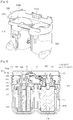
- the case unit 500 may have a shape corresponding to the filtering unit 400 to allow the filtering unit 400 to be installed therein.
- the filter insertion part 500b may be formed in the case unit 500 to allow the water purifying filter 200 is inserted thereinto when the filtering unit 400 is connected to the case unit 500.
- two filter insertion parts 500b are formed in the case unit 500 so that two water purifying filters 200 can be included in the filtering unit 400.
- the number of the filter insertion parts 500b is not particularly limited and any number of filter insertion parts 500b may be provided as long as it corresponds to the water purifying filters 200 included in the filtering unit 400.
- a water purifier P includes a water purifier housing H and the foregoing water purifying filter assembly module 100.
- the foregoing water purifying filter assembly module 100 is installed in the water purifier housing H.
- the head unit 300 included in the water purifying filter assembly module 100 is exposed from an upper surface of the water purifier housing H. Accordingly, the head unit 300 of the water purifying filter assembly module 100 may serve as a cover of the water purifier housing H. Also, as shown in the embodiment illustrated in FIG. 9 , the head unit 300 of the water purifying filter assembly module 100 is exposed to the outside when a top cover C of the water purifier housing H is separated.
- the filtering unit in which one or more water purifying filters are connected to the head unit is connected to the case unit such that it is installed in the case unit, raw water can flow into the filtering unit without a pipe connection operation and purified water filtered by the water purifying filters can flow out therefrom, the filtering unit in which water purifying filters are connected to a head unit can be connected to a case unit such that it is easily installed therein, or separated therefrom, and the water purifying filter can be replaced even in a narrow space.
- two or more different types of water purifying filters can be connected in series, two or more water purifying filters may not be replaced together, water filtering efficiency by the water purifying filters can be enhanced, and two or more water purifying filters can be connected to appropriate filter connection parts, respectively, among two or more filter connection parts included in the head unit to allow the water purifying filters to be connected thereto.
Landscapes
- Chemical & Material Sciences (AREA)
- Chemical Kinetics & Catalysis (AREA)
- Life Sciences & Earth Sciences (AREA)
- Hydrology & Water Resources (AREA)
- Engineering & Computer Science (AREA)
- Environmental & Geological Engineering (AREA)
- Water Supply & Treatment (AREA)
- Organic Chemistry (AREA)
- Water Treatment By Sorption (AREA)
- Separation Using Semi-Permeable Membranes (AREA)
Description
- The present invention relates to a water purifying filter assembly module in which one or more water purifying filters are connected or separated, and in the case that the water purifying filters are connected, raw water is introduced to the water purifying filters and purified water filtered by the water purifying filters flows out therefrom, and a water purifier having the same, and more particularly, to a water purifying filter assembly module in which when a filtering unit in which one or more water purifying filters are connected to a head unit is installed in and connected to a case unit, raw water is introduced to the filtering unit without a pipe connection operation, and purified water filtered by the filtering unit flows out therefrom, and a water purifier having the same.
- A water purifying filter assembly module is a device installed in a water purifier, or the like, in which one or more water purifying filters are connected, raw water is introduced to the water purifying filters, and purified water filtered by the water purifying filters flows to the outside, e.g., to a purified water tank storing purified water.
- A related art water purifying filter assembly module is provided in a water purifier, or the like, and includes a head unit having one or more water purifying filters connected thereto or separated therefrom, supplies raw water to the connected water purifying filters, and allows purified water filtered by the water purifying filters to flow out therefrom to the outside.
- In the related art water purifying filter assembly module, since the head unit, to and from which the water purifying filters are connected or separated, is disposed in the water purifier, or the like, a certain amount of space is required for the water purifying filters to be connected or separated.
- Thus, when the water purifier, or the like, is positioned in a narrow space, it is not easy for the water purifying filters to be connected to or separated from the head unit, making it difficult to replace the water purifying filters.
- Further, when the water purifying filters are replaced, water may be leaked from the head unit or the water purifying filter, and in this case, since water is leaked to the water purifier equipped with the head unit, or the like, electronic equipment may suffer a failure, or the water purifier may be contaminated.
- Also, in the case of connecting two or more water purifying filters to the related art water purifying filter assembly module, the two or more water purifying filters cannot be connected in series. Namely, in the case of connecting two or more water purifying filters to the related art water purifying filter assembly module, two or more water purifying filters are connected to the water purifying filter assembly module in parallel.
- Thus, water may be simultaneously introduced to the two or more water purifying filters, and water filtered by the two or more water purifying filters simultaneously flows out therefrom. Thus, two or more different types of water purifying filter cannot be connected to the water purifying filter assembly module, and since only the same type of water purifying filter can be used, water filtering efficiency based on water purifying filters may be degraded.
- In addition, since only the same type of two or more water purifying filters are connected to the water purifying filter assembly module, the two or more water purifying filters should be replaced together. Namely, if only some of the same type of water filters, among two or more water purifying filters, are replaced, water filtration efficiency is degraded by the unreplaced water purifying filter.
-
WO 2008/035830 A1 describes a filter cartridge and a filter head including: a filter housing having an inlet port through which unfiltered water is introduced, an outlet port through which water filtered by a filtering member is drained, and a filtering member; a cap member engaged with the filter housing, forming a chamber region where unfiltered water is temporarily stored, and having an inlet formed in an outer direction through which unfiltered water is introduced and a sleeve formed in an inner direction at a center portion; and a check valve disposed in the chamber region, and which blocks water flow from the inlet toward the filter housing before the filter housing is engaged and allows water flow toward the filter housing when the filter housing is engaged. The filter housing is engaged with the cap member by rotating the filter housing. -
US 2005/178708 A1 describes an automatic water filtration and purification system to allow a continuous water flow to downstream fixtures while simultaneously and automatically regularly flushing and cleaning in-path filter media. The automatic water filtration and purification system has at least one filter to remove impurities from a water in-path through-put. A cleaner is coupled to the at least one filter to clean the at least one filter. A controller is coupled to the at least one filter to regulate automatic operation of the cleaner wherein continuous operation of water flow to fixtures downstream of the at least one filter is essentially uninterrupted during the operation of the cleaner and the controller. -
KR 2009 0005574 A -
KR 2010 0051447 A -
EP 2 206 543 A1 describes a water purifying system having a bypass path supplying raw water to an outlet when a filter assembly is separated from a valve assembly. The water purifying system includes a valve assembly having a valve cover with an inlet and an outlet, and a head member moved up and down within the valve cover to form an inflow path and an outflow path, and a filter assembly removably connected to the valve assembly and mounted with a filter. When the filter assembly is connected to the valve assembly through a linear motion, the filter assembly advances the head member so that a fluid flown in through the inlet is guided to the outlet passing through the filter. When the filter assembly is separated from the valve assembly, the head member is retreated so that the fluid flown through the inlet is guided to the outlet bypassing the filter. -
KR 2010 0050335 A -
US 2008/047900 A1 describes a filter, comprising: a housing defining an inner cavity; an inner sleeve disposed within the housing, the inner sleeve having portions in a spaced relationship with respect to the an interior surface of the inner cavity; a plurality of tab members extending away from the inner sleeve, the tab members being configured to be removably secured to a feature of a cap, the cap being configured to engage the housing to provide a first position and a second position with respect to the housing, wherein the first position seals the inner sleeve to the housing and a fluid filtration path from an inlet of the filter to an outlet of the filter is defined by the inner sleeve and the second position provides a fluid drain path through an opening in the cap, the fluid drain path being closed when the cap is in the first position; and a filtration media disposed within an interior area of the inner sleeve, wherein the filtration media is disposed in the fluid filtration path and fluid flow through the outlet opening must pass through the filtration media. -
JP H04 102694 U - The present invention has been devised through recognition of any one of the issues or problems evident in the related art.
- An aspect of the present invention provides a water purifying filter assembly module in which when a filtering unit in which one or more water purifying filters are connected to a head unit is installed in and connected to a case unit, raw water is introduced to the filtering unit without a pipe connection operation, and purified water filtered by the filtering unit flows out therefrom, and a water purifier having the same.
- An aspect of the present invention also provides a water purifying filter assembly module in which a filtering unit in which water purifying filters are connected to a head unit is connected to a case unit or separated therefrom such that it is easily installed therein.
- An aspect of the present invention also provides a water purifying filter assembly module in which a water purifying filter may be replaced, even in a narrow space.
- An aspect of the present invention also provides a water purifying filter assembly module in which when a filtering unit in which water purifying filters are connected to a head unit is separated from a case unit, raw water is prevented from flowing into the water purifying filters.
- An aspect of the present invention also provides a water purifying filter assembly module in which when a filter unit including water purifying filters connected to a head unit is separated, water is allowed to be leaked to a case unit to thus prevent contamination or an incident due to leaking water.
- A water purifying filter assembly module and a water purifier having the same in relation to an embodiment for realizing at least one of the tasks may have the following features.
- The present invention is largely based on a technique in which when a filtering unit in which one or more water purifying filters are connected to a head unit is connected to a case unit so as to be installed therein, raw water is introduced to the filtering unit without a pipe connection operation, and purified water filtered by the filtering unit flows out therefrom.
- According to an aspect of the present invention, there is provided a water purifying filter assembly module including: a head unit, to or from which one or more water purifying filters are connected or separated, allowing raw water to flow into the water purifying filters and purified water filtered by the water purifying filters to flow out therefrom, when the water purifying filters are connected to the head unit; and a case unit, to or from which a filtering unit in which the water purifying filters are connected to the head unit is connected or separated so as to be installed therein, allowing raw water to flow into the head unit and purified water from the head unit to flow out therefrom, when the filtering unit is connected to the case unit.
- In this case, when the filtering unit is separated from the case unit, the filtering unit may be lifted upwardly from the case unit.
- Also, the head unit includes: a head unit main body; a filter connection part disposed in the head unit main body to allow raw water to flow into the water purifying filters and purified water filtered by the water purifying filters to flow out therefrom, when the water purifying filters are connected; and a detaching part disposed in the head unit main body to facilitate a connection to or separation from the case unit.
- One detaching part may be disposed on either side of the head unit main body.
- Also, the detaching part may include a detaching member elastically supported by the head unit main body in order to connect the filtering unit to the case unit or separate the filtering unit therefrom.
- The detaching part may include: an elastic member inserted into an insertion projection formed on a head unit main body; and a detaching member elastically supported by the elastic member and configured to be caught by the case unit when connected to the case unit and released from the case unit when separated from the case unit.
- Also, a handle portion may be formed on one side of the detaching member such that the handle portion is inserted into and protruded from a handle hole formed in the head unit main body, and a stopping projection may be formed on the other side of the detaching member such that the stopping projection is inserted into and protruded from an insertion hole formed in the head unit main body and caught by a stopping hole formed in the case unit when connected to the case unit.
- The head unit further includes: an inlet/outlet part disposed in the head unit main body and allowing raw water introduced to the case unit to flow into the filter connection part and purified water flowing out from the filter connection unit to flow out therefrom through the case unit, when connected to the case unit.
- Also, the inlet/outlet part includes: a raw water inlet having one side disposed in the head unit main body so as to be connected to an inlet connection portion included in the filter connection part and the other side inserted into an inlet insertion part disposed in the case unit, when connected to the case unit; and a purified water outlet having one side disposed in the head unit main body so as to be connected to an outlet connection portion included in the filter connection part and the other side inserted into an outlet insertion part provided in the case unit, when connected to the case unit.
- Also, the filter connection part includes: an inlet connection portion connected to an inlet disposed in the water purifying filter when the water purifying filter is connected; and an outlet connection portion connected to an outlet disposed in the water purifying filter when the water purifying filter is connected.
- The case unit includes the inlet insertion part connected to a raw water source, the raw water inlet portion included in the head unit being inserted thereinto when the filtering unit is connected; and the outlet insertion part, into which the purified water outlet included in the head unit is inserted, when the filtering unit is connected.
- Also, the inlet insertion part includes an opening and closing member opening a flow channel formed in the inlet insertion part when the raw water inlet is inserted therein and closing the flow channel when the raw water inlet is separated.
- The opening and closing member may be elastically supported by an elastic member provided in the inlet insertion part.
- Also, the stopping hole may be formed in an upper portion of the case unit to allow a stopping projection formed in the detaching member included in the head unit to be caught therein when the filtering unit is connected.
- According to another aspect of the present invention, there is provided a water purifier including: a water purifier housing; and the foregoing water purifying filter assembly module installed in the water purifier housing, wherein the head unit included in the water purifying filter assembly module may be exposed from an upper surface of the water purifier housing or may be exposed to the outside when a top cover of the water purifier housing is separated.
- According to an embodiment of the present invention, when the filtering unit in which one or more water purifying filters are connected to the head unit is connected to the case unit such that it is installed in the case unit, raw water can flow into the filtering unit without a pipe connection operation and purified water filtered by the water purifying filters can flow out therefrom.
- Also, according to an embodiment of the present invention, the filtering unit in which water purifying filters are connected to a head unit can be connected to a case unit such that it is easily installed therein or separated therefrom.
- Also, according to an embodiment of the present invention, since the filtering unit is completely lifted upwardly by separating it from the case unit and the water purifying filter is separated from the head unit, the water purifying filter can be replaced even in a narrow space.
- Also, according to an embodiment of the present invention, when the filtering unit in which the water purifying filters are connected to the head unit is separated from the case unit, the elastically supported opening and closing member closes the opening and closing member to prevent raw water from flowing into the water purifying filters.
- Also, according to an embodiment of the present invention, when the filtering unit in which the water purifying filters are connected to the head unit is separated from the case unit, although water is leaked, it is leaked to the case unit, thus preventing contamination of the interior of the water purifier or an electric incident, or the like, due to the dripping water.
- Also, according to an embodiment of the present invention, two or more different types of water purifying filters may be connected in series.
- Also, according to an embodiment of the present invention, two or more water purifying filters may not be replaced together.
- Also, according to an embodiment of the present invention, water filtering efficiency by the water purifying filters can be enhanced.
- Also, according to an embodiment of the present invention, two or more water purifying filters can be connected to appropriate filter connection parts, respectively, among two or more filter connection parts included in the head unit to allow the water purifying filters to be connected thereto.
-
-
FIG. 1 is a perspective view of a water purifying filter assembly module according to an embodiment of the present invention. -
FIG. 2 is a view illustrating water purifying filters of the water purifying filter assembly module according to an embodiment of the present invention. -
FIG. 3 is an exploded perspective view of a head unit of the water purifying filter assembly module according to an embodiment of the present invention. -
FIG. 4 is a perspective view of a case unit of the water purifying filter assembly module according to an embodiment of the present invention. -
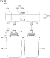
FIG. 5 is a cross-sectional view taken along line A-A inFIG. 1 . -
FIG. 6 is a cross-sectional view taken along line B-B inFIG. 1 . -
FIG. 7 is a cross-sectional view illustrating a state in which a filtering unit is separated from the case unit in the water purifying filter assembly module according to an embodiment of the present invention. -
FIG. 8 is a cross-sectional view illustrating a state in which water purifying filters are separated from the head unit in the water purifying filter assembly module according to an embodiment of the present invention. -
FIG. 9 is a perspective view of a water purifier according to an embodiment of the present invention. - To help understand the foregoing features of the present invention, a water purifying filter assembly module and a water purifier having the same in relation to an embodiment of the present invention will be described in detail with reference to the accompanying drawings.
- Hereinafter, embodiments most appropriate to help in an understanding of the technical features of the present invention will be described, the technical features of the present invention are not limited by the described embodiments and merely illustrate the implementation of the present invention through the embodiments described hereinafter. Thus, the present invention can be variably modified within the scope of the present invention through the embodiments described below, and such modifications are within the scope of the present invention. In order to help understand the embodiments described hereinafter, the like or similar reference numerals are used for relevant components among the components having the same function in the respective embodiments in the accompanying drawings.
- Embodiments in relation to the present invention are based on a concept that when a filtering unit in which one or more water purifying filters are connected to a head unit is installed in and connected to a case unit, raw water is introduced to the filtering unit without a pipe connection operation, and purified water filtered by the filtering unit flows out therefrom.
- As shown in an embodiment illustrated in
FIGS. 1 and5 , a water purifyingfilter assembly module 100 according to an embodiment of the present invention includes ahead unit 300 to or from which one or morewater purifying filters 200 are connected or separated and acase unit 500 to or from which afiltering unit 400 including thewater purifying filters 200 connected to thehead unit 300 is connected so as to be installed therein or separated. - As shown in the embodiment illustrated in
FIGS. 2 and5 , thewater purifying filter 200 has aninlet 210 through which raw water or purified water filtered by a differentwater purifying filter 200 flows. Also, as shown in the illustrated embodiment, thewater purifying filter 200 may have afiltering member 230 filtering raw water introduced through the foregoinginlet 210 or purified water introduced after being filtered by the differentwater purifying filter 200. Also, thewater purifying filter 200 may have anoutlet 220 allowing filtered purified water to flow out therethrough. - Also, as shown in the embodiment illustrated in
FIG. 2 , thewater purifying filter 200 may have aconnection protuberance 240 formed thereon. Theconnection protuberance 240 of thewater purifying filter 200 may be caught by a stopping projection (not shown) formed on a filter connection part 320 (to be described) included in thehead unit 300 or released therefrom according to rotation of thewater purifying filter 200. - Through such a configuration, the
water purifying filter 200 may be connected to thehead unit 300, specifically, to thefilter connection part 320 of thehead unit 300 in the illustrated embodiment, through rotation, as illustrated inFIGS. 5 and7 , or may be separated therefrom as illustrated inFIG. 8 . - In this case, as shown in the embodiment illustrated in
FIG. 2 , thewater purifying filter 200 may have arotation preventing projection 260. Also, as shown in the embodiment illustrated inFIG. 4 , arotation preventing recess 530 may be formed in afilter insertion part 500b formed to allow thewater purifying filter 200 to be inserted into the case unit 500 (to be described). - Through such a configuration, as illustrated in
FIG. 5 , when thefiltering unit 400 connected to thehead unit 300 is inserted into thefilter insertion part 500b so as to be installed in thecase unit 500, therotation preventing projection 260 of thewater purifying filter 200 may be inserted into therotation preventing recess 530 of thefilter insertion part 500b of thecase unit 500. Accordingly, thewater purifying filter 200 inserted in thefilter insertion part 500b may not be rotated. Thus, thewater purifying filter 200 inserted in the filter insertion part is prevented, for example, from being rotated by pressure of water introduced into thewater purifying filter 200 and separated from thefilter connection part 320. - Also, as shown in the embodiment illustrated in
FIG. 2 , thewater purifying filter 200 has anidentification projection 250. Also, as shown in the illustrated embodiment, theidentification projection 250 is not formed on the differentwater purifying filter 200. - In addition, as shown in the embodiment illustrated in
FIG. 5 , adifferent identification projection 350 is formed on the filter connection part (to be described) included in thehead unit 300, to which thewater purifying filter 200 with theidentification projection 250 formed thereon is not to be connected. Also, thedifferent identification projection 350 is not formed on afilter connection part 320 to which thewater purifying filter 200 is to be connected. - Thus, the
identification projection 250 formed on thewater purifying filter 200 may be interfered with by theidentification projection 350 formed on thefilter connection part 320, and thus, thewater purifying filter 200 is not connected to thefilter connection part 320 to which thewater purifying filter 200 should not be connected, and is only connected to thefilter connection part 320 to which thewater purifying filter 200 should be connected. Namely, two or morewater purifying filters 200 are connected to appropriatefilter connection parts 320, respectively, among the two or morefilter connection parts 320 included in thehead unit 300 to allow thewater purifying filters 200 to be connected thereto. - As shown in the embodiment illustrated in
FIGS. 5 ,7 , and8 , one or morewater purifying filters 200 may be connected to thehead unit 300 or separated therefrom. As shown in the illustrated the embodiment, twowater purifying filters 200 may be connected to or separated from thehead unit 300. However, the number ofwater purifying filters 200 connected to or separated from thehead unit 300 is not limited thereto and any number ofwater purifying filters 200 may be connected to or separated from thehead unit 300 as long as it is one or more. - Also, the
head unit 300 is configured to allow raw water to be introduced to thewater purifying filter 200 and purified water filtered by thewater purifying filter 200 to flow out therefrom, when thewater purifying filter 200 is connected to thehead unit 300. - To this end, as shown in the embodiment illustrated in
FIG. 3 , thehead unit 300 includes a head unitmain body 310, thefilter connection part 320, and a detachingpart 330. - As shown in the embodiment illustrated in
FIGS. 3 and5 , the head unitmain body 310 may include acover member 310a and amain body member 310b. The head unitmain body 310 may be configured by connecting thecover member 310a to an opened upper portion of themain body member 310b. To this end, as shown in the embodiment illustrated inFIG. 3 , thecover member 310a includes aninsertion projection 311, and themain body member 310b may include aninsertion recess 312. When thecover member 310a is connected to the opened upper portion of themain body member 310b, the foregoinginsertion projection 311 may be inserted into theinsertion recess 312. - However, the configuration in which the
cover member 310a is connected to the opened upper portion of themain body member 310b to form the head unitmain body 310 is not limited thereto, and any known configuration may be employed as long as thecover member 310a is connected to the opened upper portion of themain body member 310b to form the head unitmain body 310. - As illustrated in
FIGS. 3 and5 , thefilter connection part 320 may be disposed in the head unitmain body 310, i.e., specifically, in themain body member 310b of the head unitmain body 310 in the illustrated embodiment, to allow raw water to be introduced to thewater purifying filter 200 and purified water filtered by thewater purifying filter 200 to flow out therefrom, when thewater purifying filter 200 is connected thereto. - As illustrated, two
filter connection parts 320 may be included in thehead unit 300. Accordingly, twowater purifying filters 200 may be connected to or separated from thehead unit 300. However, the number of thefilter connection parts 320 included in thehead unit 300 is not limited thereto and one filter connection part or three or more filter connection parts may be included in thehead unit 300. When onefilter connection part 320 is included in thehead unit 300, only onewater purifying filter 200 may be connected to or separated from thehead unit 300. When three or morefilter connection parts 320 are included in thehead unit 300, three or morewater purifying filters 200 may be connected to or separated from thehead unit 300. - As shown in the embodiment illustrated in
FIGS. 3 and5 , thefilter connection part 320 includes aninlet connection portion 321 and anoutlet connection portion 322. - As shown in the embodiment illustrated in
FIG. 5 , theinlet connection portion 321 may be connected to theinlet 210 provided in thewater purifying filter 200 when thewater purifying filter 200 is connected. Thus, as illustrated inFIG. 5 , raw water introduced to theinlet connection portion 321 may flow to theinlet 210 of thewater purifying filter 200. - Also, as shown in the embodiment illustrated in
FIG. 5 , when thewater purifying filter 200 is connected, theoutlet connection portion 322 may be connected to theoutlet 220 provided in thewater purifying filter 200. Thus, as illustrated inFIG. 5 , raw water introduced to thewater purifying filter 200 through theinlet connection portion 321 and theinlet 210 of thewater purifying filter 200 is filtered by the filteringmember 230 provided in thewater purifying filter 200, while passing therethrough, and subsequently flows out therefrom through theoutlet 220 of thewater purifying filter 200 and theoutlet connection portion 322. - As shown in the embodiment illustrated in
FIGS. 3 and5 , twofilter connection parts 320 may be provided in the head unitmain body 310, specifically, in themain body members 310b of the head unitmain body 310. As shown in the illustrated embodiment, the twofilter connection parts 320 may be connected by a connection pipe T. Namely, as shown in the illustrated embodiment, one side and the other side of the connection pipe T may be connected to the twofilter connection parts 320 by a fitting member F, respectively. - Also, as shown in the embodiment illustrated in
FIGS. 3 and5 , one side of the connection pipe T may be connected to theoutlet connection portion 322 of thefilter connection part 320, and the other side of the connection pipe T may be connected to theinlet connection portion 321 of the otherfilter connection part 320. Accordingly, as illustrated inFIG. 5 , purified water filtered by onewater purifying filter 200 may flow out therefrom from theoutlet connection portion 322 of the onefilter connection part 320 connected thereto, flows through the connection pipe T, and subsequently flows into theinlet connection portion 321 of the otherfilter connection part 320, thus being introduced to the otherwater purifying filter 200. - Through such a configuration, two or more types of
water purifying filters 200 may be connected in series by connecting them to thehead unit 300. Thus, in comparison to a case in which the same type ofwater purifying filters 200 are connected in parallel, water filtering efficiency by thewater purifying filters 200 can be enhanced. - Because different types of
water purifying filters 200 have different life spans, thewater purifying filters 200 connected to thehead unit 300 may not necessarily be replaced together. - Meanwhile, as shown in the embodiment illustrated in
FIGS. 2 and5 , one or more sealing members R may be disposed in theinlet 210 and theoutlet 220 of thewater purifying filter 200. Accordingly, as described above and as illustrated inFIG. 5 , since theinlet 210 and theoutlet 220 are connected to theinlet connection portion 321 and theoutlet connection portion 322 of thefilter connection part 320, respectively, when raw water or purified water flows, it is not leaked to the outside. - The detaching
part 330 may be disposed in the head unitmain body 310, i.e., in themain body member 310b of the head unitmain body 310 in the embodiment illustrated inFIG. 3 . By virtue of the detachingpart 330, thefiltering unit 400 in which thewater purifying filter 200 is connected to thehead unit 300 may be easily connected to thecase unit 500 as illustrated inFIG. 5 or may be easily separated from thecase unit 500 as illustrated inFIG. 7 . - As shown in the embodiment illustrated in
FIG. 3 , two detachingparts 330 may be provided in both sides of the head unitmain body 310, i.e., in both sides of themain body member 310b of the head unitmain body 310 in the illustrated embodiment. However, the number of the detachingparts 330 is not limited thereto and any number of detaching parts may be provided as long as thefiltering unit 400 in which thewater purifying filter 200 is connected to thehead unit 300 is easily connected to thecase unit 500 or easily separated from thecase unit 500. - The detaching
part 330 may include a detachingmember 332 elastically supported in the head unitmain body 310 in order to connect thefiltering unit 400 to thecase unit 500 or separate thefiltering unit 400 from thecase unit 500. - To this end, as shown in the embodiment illustrated in
FIG. 3 , the detachingpart 330 may include anelastic member 331 and the foregoing detachingmember 332. - As shown in the embodiment illustrated in
FIG. 3 , theelastic member 331 may be inserted into the head unitmain body 310, specifically, into aninsertion projection 310c provided in themain body member 310b of the head unitmain body 310. - As shown in the embodiment illustrated in
FIG. 3 , the detachingmember 332 may be elastically supported by the foregoingelastic member 331. Also, the detachingmember 332 may configured to allow thefiltering unit 400 in which thewater purifying filter 200 is connected to thehead unit 300 to be caught in thecase unit 500 when thefiltering unit 400 is connected to thecase unit 500 as illustrated inFIG. 5 , and allow thefiltering unit 400 to be released from thecase unit 500 when thefiltering unit 400 is separated from thecase unit 500 as illustrated inFIG. 7 . Accordingly, as mentioned above, thefiltering unit 400 may be easily connected to thecase unit 500 or easily separated from thecase unit 500. - To this end, as illustrated in
FIGS. 3 and6 through 8 , ahandle portion 332a may be formed on one side of the detachingmember 332, and a stoppingprojection 332b may be formed on the other side of the detachingmember 332. - As shown in the embodiment illustrated in
FIGS. 3 and6 through 8 , thehandle portion 332a may be inserted into the head unitmain body 310, specifically into ahandle hole 310d formed in themain body member 310b of the head unitmain body 310, so as to be protruded. Thus, the user may easily press thehandle portion 332a. Also, to this end, thehandle portion 332a may have a plurality of abrasive projections or a plurality of abrasive recesses formed thereon as illustrated. - As shown in the embodiment illustrated in
FIGS. 3 and6 through 8 , the stoppingprojection 332b may be inserted into aninsertion hole 310e formed on the head unitmain body 310, specifically on themain body member 310b of the head unitmain body 310 in the illustrated embodiment, so as to be protruded. Also, the stoppingprojection 332b may be caught in a stoppinghole 500a formed in thecase unit 500 when thefiltering unit 400 in which thewater purifying filter 200 is connected to thehead unit 300 is connected to thecase unit 500, as illustrated inFIG. 6 . - Namely, when the user applies external force by pressing the
handle portion 332a of the detachingmember 332, the detachingmember 332, overcoming elastic force of theelastic member 331, may move inwardly of the head unitmain body 310, specifically, themain body member 310b of the head unitmain body 310. - In this state, as illustrated in
FIG. 5 , thefiltering unit 400 in which thewater purifying filter 200 is connected to thehead unit 300 is insertedly installed in thecase unit 500. When external force applied to thehandle portion 332a of the detachingmember 332 is removed, the detachingmember 332 is moved to an outer side of the head unitmain body 310, specifically, themain body member 310b of the head unitmain body 310 in the illustrated embodiment, so as to be returned to its original position. - Accordingly, as illustrated in
FIGS. 5 and6 , when thefiltering unit 400 in which thewater purifying filter 200 is connected to thehead unit 300 is insertedly installed in thecase unit 500, the stoppingprojection 332b of the detachingmember 332 may be caught in the stoppinghole 500a formed in thecase unit 500 as illustrated inFIG. 6 . Thus, thefiltering unit 400 in which thewater purifying filter 200 is connected to thehead unit 300 is insertedly installed in thecase unit 500 such that it is not separated from thecase unit 500 as illustrated. - Also, in the state illustrated in
FIG. 6 , when the user applies external force to thehandle portion 332a of the detachingmember 332 by pressing thehandle portion 332a, as mentioned above, the detachingmember 332, overcoming elastic force of theelastic member 331, is moved inwardly of the head unitmain body 310, specifically, inwardly of themain body member 310b of the head unitmain body 310 in the illustrated embodiment. Accordingly, the stoppingprojection 332b of the detachingmember 332 is released from the stoppinghole 500a of thecase unit 500. Accordingly, as illustrated inFIG. 7 , thefiltering unit 400 insertedly positioned in thecase unit 500 can be easily separated from thecase unit 500. - Also, as described above, after the
filtering unit 400 is separated from thecase unit 500 and external force applied to thehandle portion 332a of the detachingmember 332 is removed, the detachingmember 332 is returned to its original position by elastic force of theelastic member 331. - Accordingly, the
filtering unit 400 in which thewater purifying filter 200 is connected to thehead unit 300 may be connected to and separated from thecase unit 500 such that it is easily installed therein. - Meanwhile, as mentioned above, after the
filtering unit 400 in which thewater purifying filter 200 is connected to thehead unit 300 is separated from thecase unit 500, thewater purifying filter 200 may be rotated to be separated from thehead unit 300 as illustrated inFIG. 8 . - Also, after a new
water purifying filter 200 is connected to thehead unit 300 through rotation, thefiltering unit 400 in which thewater purifying filter 200 is connected to thehead unit 300 may be connected to thecase unit 500 such that it is installed in thecase unit 500. - Thus, rather than providing the
head unit 300 to which thewater purifying filter 200 is directly connected as in the related art to a water purifier, or the like, thecase unit 500 to which thefiltering unit 400 in which thewater purifying filter 200 is connected to thehead unit 300 is connected may be provided to a water purifier, or the like. - Also, after the
filtering unit 400 in which thewater purifying filter 200 is connected to thehead unit 300 is separated from thecase unit 500, thewater purifying filter 200 may be replaced, and thefiltering unit 400 in which thewater purifying filter 200 is connected to thehead unit 300 may be connected to thecase unit 500. - Also, when the
filtering unit 400 is separated from thecase unit 500, it may be lifted upwardly of thecase unit 500. Thus, because thewater purifying filter 200 is not connected to thehead unit 300 or separated from thehead unit 300 with thehead unit 300 connected to a water purifier (not shown) as in the related art, thewater purifying filter 200 may be replaced even in a narrow space. - Also, the
head unit 300 further includes an inlet/outlet part 340. As shown in the embodiment illustrated inFIG. 3 , the inlet/outlet part 340 may be provided in the head unitmain body 310, specifically, in themain body member 310b of the head unitmain body 310 in the illustrated embodiment. As illustrated inFIG. 6 , the inlet/outlet part 340 is configured to allow raw water introduced to thecase unit 500 to flow into thefilter connection part 320 and purified water flowing out of thefilter connection part 320 to flow out therefrom through thecase unit 500, when thefiltering unit 400 in which thewater purifying filter 200 is connected to thehead unit 300 is connected to thecase unit 500. To this end, as shown in the embodiment illustrated inFIGS. 3 and6 , the inlet/outlet part 340 includes araw water inlet 341 and apurified water outlet 342. - As shown in the embodiment illustrated in
FIG. 3 , one side of theraw water inlet 341 may be disposed on the head unitmain body 310, specifically, on themain body member 310b in the illustrated embodiment, so as to be connected to theinlet connection portion 321 of the foregoingfilter connection part 320 as illustrated inFIG. 6 . One side of theraw water inlet 341 may be connected to the other side of the connection pipe T having one side connected to theinlet connection portion 321 of thefilter connection part 320 so as to be connected to theinlet connection portion 321 of thefilter connection part 320 as in the illustrated embodiment. One side and the other side of the connection pipe T may be connected to one side of theinlet connection portion 321 of thefilter connection part 320 and one side of theraw water inlet 341 by the fitting member F. - Also, as illustrated in
FIG. 6 , when thefiltering unit 400 in which thewater purifying filter 200 is connected to thehead unit 300 is connected to thecase unit 500, the other side of theraw inlet 341 is inserted to be connected to an inlet insertion part 510 (to be described) provided in thecase unit 500 and connected to a raw water source (not shown) such as tap water, or the like. - Accordingly, when raw water from the raw water source is introduced to the
inlet insertion part 510, the raw water introduced to theinlet insertion portion 510 may be introduced to theraw water inlet 341. The raw water introduced to theraw water inlet 341 may flow to theinlet connection portion 321 of the foregoingfilter connection part 320. Also, the raw water flowing to theinlet connection portion 321 of thefilter connection part 320 may be introduced to thewater purifying filter 200 through theinlet 210 of thewater purifying filter 200 connected to theinlet connection portion 321 of thefilter connection part 320. - As shown in the embodiment illustrated in
FIGS. 3 and6 , one side of the purifiedwater outlet 342 may be provided in the head unitmain body 310, specifically, in themain body member 310b of the head unitmain body 310, so as to be connected to theoutlet connection portion 322 of the foregoingfilter connection part 320. As shown in the illustrated embodiment, one side of the purifiedwater outlet 342 may be connected to the other side of the connection pipe T having one side connected to theoutlet connection portion 322 of thefilter connection part 320, so as to be connected to theoutlet connection portion 322 of thefilter connection part 320. As shown in the illustrated embodiment, one side and the other side of the connection pipe T may be connected to one side of theoutlet connection portion 322 of thefilter connection part 320 and one side of the purifiedwater outlet 342 by the fitting member F. - Also, as illustrated in
FIG. 6 , when thefiltering unit 400 in which thewater purifying filter 200 is connected to thehead unit 300 is connected to thecase unit 500, the other side of the purifiedwater outlet 342 may be inserted in and connected to theoutlet insertion part 520 provided in thecase unit 500. Accordingly, purified water flowing out of theoutlet 220 of thewater purifying filter 200 after being filtered by thewater purifying filter 200 may be introduced to the purifiedwater outlet 342 through theoutlet connection portion 322 of thefilter connection part 320. The water introduced to the purifiedwater outlet 342 may be introduced to theoutlet insertion part 520 so as to flow out therefrom to the outside. - Meanwhile, as shown in the embodiment illustrated in
FIGS. 3 and6 , one or more sealing members R may be provided on the other side of theraw water inlet 341 and the purifiedwater outlet 342. Accordingly, as mentioned above, when thefiltering unit 400 in which thewater purifying filter 200 is connected to thehead unit 300 is connected to thecase unit 500 and raw water is introduced to theraw water inlet 341 through theinlet insertion part 510 of thecase unit 500, the raw water may not be leaked to the outside. Also, as mentioned above, when purified water flowing out of the purifiedwater outlet 342 flows to theoutlet insertion part 520 of thecase unit 500, it may not be leaked to the outside. - The
filtering unit 400 in which thewater purifying filter 200 is connected to thehead unit 300 may be connected to thecase unit 500 such that it is installed therein or separated therefrom. Also, thecase unit 500 may be configured to allow raw water to be introduced to thehead unit 300 and purified water flowing out of thehead unit 300 to flow out therefrom, when thefiltering unit 400 is connected. To this end, as shown in the embodiment illustrated inFIGS. 4 and6 , thecase unit 500 includes theinlet insertion part 510 and theoutlet insertion part 520. - The
inlet insertion part 510 is connected to, for example, a raw water source (not shown) such as tap water, or the like. Also, as illustrated inFIG. 6 , when thefiltering unit 400 is connected to thecase unit 500, the foregoingraw water inlet 341 included in thehead unit 300 is inserted to be connected. Accordingly, as described above and as illustrated inFIG. 6 , raw water from the raw water source is introduced to thehead unit 300, i.e., theinlet connection portion 321 of thefilter connection part 320 of the head unit, through theinlet insertion part 510 and theraw water inlet 341, so as to be introduced to theinlet 210 of thewater purifying filter 200. - Meanwhile, as shown in the embodiment illustrated in
FIG. 6 , theinlet insertion part 510 includes an opening and closingmember 511. When theraw water inlet 341 is inserted, a flow channel formed in theinlet insertion part 510 may be opened by the opening and closingmember 511, and when theraw water inlet 341 is separated, the flow channel may be closed by the opening and closingmember 511. Also, the opening and closingmember 511 may be elastically supported by theelastic member 512 provided in theinlet insertion part 510. - Through such a configuration, as illustrated in
FIG. 6 , when thefiltering unit 400 is connected to thecase unit 500 so theraw water inlet 341 is insertedly connected to theinlet insertion portion 510, the opening and closingmember 511 may overcome elastic force of theelastic member 512 by theraw water inlet 341 so as to be moved. Accordingly, as illustrated inFIG. 6 , the flow channel formed in theinlet insertion part 510 may be opened. Raw water introduced into theinlet insertion part 510 may then flow to theraw water inlet 341. - Also, as illustrated in
FIG. 7 , when thefiltering unit 400 is separated from thecase unit 500 so theraw water inlet 341 is separated from theinlet insertion part 510, as illustrated, the opening and closingmember 511 may be moved by elastic force of theelastic member 512 in a direction opposite to that described above. Accordingly, as illustrated, the flow channel formed in theinlet insertion part 510 may be closed. Thus, raw water introduced to theinlet insertion part 510 may not flow. - Through such a configuration, when the
filtering unit 400 is connected to thecase unit 500, as illustrated inFIG. 6 , raw water from the raw water source may be introduced to thehead unit 300 of thefiltering unit 400. When thefiltering unit 400 is separated from thecase unit 500, as illustrated inFIG. 7 , raw water may not be introduced to thehead unit 300 of thefiltering unit 400. - Thus, without an opening and closing valve, raw water may be supplied to the
head unit 300 or supply of raw water to thehead unit 300 may be stopped by simply connecting thefiltering unit 400 to thecase 500 or separating thefiltering unit 400 from thecase unit 500. - As illustrated in
FIG. 6 , when thefiltering unit 400 is connected to thecase unit 500, the foregoingpurified water outlet 342 included in thehead unit 300 is inserted into theoutlet insertion part 520. Accordingly, as described above and as illustrated inFIG. 6 , purified water flowing out of theoutlet 220 of thewater purifying filter 200 is introduced to theoutlet connection portion 322 of thefilter connection part 320 of thehead unit 300, flows in the purifiedwater outlet 342, and is introduced to theoutlet insertion part 520, so as to flow out therefrom to the outside. - As described above and as shown in the embodiment illustrated in
FIGS. 4 and6 , the stoppinghole 500a may be formed in an upper portion of thecase unit 500. As described above and as illustrated, when thefiltering unit 400 in which thewater purifying filter 200 is connected to thehead unit 300 is connected to thecase unit 500, the stoppingprojection 332b formed on the detachingmember 332 included in thehead unit 300 may be caught in the stoppinghole 500a. - Accordingly, when the
filtering unit 400 is connected to thecase unit 500, thefiltering unit 400 is prevented from being separated from thecase unit 500. Also, as mentioned above, theraw water inlet 341 and the purifiedwater outlet 342 insertedly connected to theinlet insertion part 510 and theoutlet insertion part 520 of thecase unit 500, respectively, as thefiltering unit 400 is connected to thecase unit 500 may not be separated. Thus, as mentioned above, theraw inlet 341 may force the opening and closingmember 511 provided in theinlet insertion part 510 to be in a position to open the flow channel formed in theinlet insertion part 510. Accordingly, raw water can be smoothly supplied to thewater purifying filter 200. Also, purified water flowing out of thewater purifying filter 200 may also smoothly flow out therefrom to the outside. - As shown in the embodiment illustrated in
FIGS. 4 and 5 , thecase unit 500 may have a shape corresponding to thefiltering unit 400 to allow thefiltering unit 400 to be installed therein. To this end, as shown in the illustrated embodiment, thefilter insertion part 500b may be formed in thecase unit 500 to allow thewater purifying filter 200 is inserted thereinto when thefiltering unit 400 is connected to thecase unit 500. In the illustrated embodiment, twofilter insertion parts 500b are formed in thecase unit 500 so that twowater purifying filters 200 can be included in thefiltering unit 400. However, the number of thefilter insertion parts 500b is not particularly limited and any number offilter insertion parts 500b may be provided as long as it corresponds to thewater purifying filters 200 included in thefiltering unit 400. - Through such a configuration, as illustrated in
FIG. 7 , when thefiltering unit 400 is separated from thecase unit 500, although water is leaked from thefiltering unit 400, it is leaked to thecase unit 500. Thus, water is prevented from being leaked to a water purifier (not shown), or the like in which thecase unit 500 is provided. Accordingly, electronic equipment provided in the water purifier, or the like, may not be broken down and the water purifier, or the like, may not be contaminated. - As shown in the embodiment illustrated in
FIG. 9 , a water purifier P according to an embodiment of the present invention includes a water purifier housing H and the foregoing water purifyingfilter assembly module 100. - As shown in the embodiment illustrated in
FIG. 9 , the foregoing water purifyingfilter assembly module 100 is installed in the water purifier housing H. Thehead unit 300 included in the water purifyingfilter assembly module 100 is exposed from an upper surface of the water purifier housing H. Accordingly, thehead unit 300 of the water purifyingfilter assembly module 100 may serve as a cover of the water purifier housing H. Also, as shown in the embodiment illustrated inFIG. 9 , thehead unit 300 of the water purifyingfilter assembly module 100 is exposed to the outside when a top cover C of the water purifier housing H is separated. - As described above, in case of using the water purifying
filter assembly module 100 and the water purifier P having the same according to an embodiment of the present invention, when the filtering unit in which one or more water purifying filters are connected to the head unit is connected to the case unit such that it is installed in the case unit, raw water can flow into the filtering unit without a pipe connection operation and purified water filtered by the water purifying filters can flow out therefrom, the filtering unit in which water purifying filters are connected to a head unit can be connected to a case unit such that it is easily installed therein, or separated therefrom, and the water purifying filter can be replaced even in a narrow space. Also, when the filtering unit in which the water purifying filters are connected to the head unit is separated from the case unit, raw water is prevented from flowing into the water purifying filters. Also, when the filtering unit in which the water purifying filters are connected to the head unit is separated from the case unit, although water is leaked, it is leaked to the case unit, thus preventing contamination or an incident due to the dripping water. - Also, two or more different types of water purifying filters can be connected in series, two or more water purifying filters may not be replaced together, water filtering efficiency by the water purifying filters can be enhanced, and two or more water purifying filters can be connected to appropriate filter connection parts, respectively, among two or more filter connection parts included in the head unit to allow the water purifying filters to be connected thereto.
Claims (9)
- A water purifying filter assembly module (100) comprising:a head unit (300), to or from which one or more water purifying filters (200) are connected or separated, allowing raw water to flow into the water purifying filters (200) and purified water filtered by the water purifying filters (200) to flow out therefrom, when the water purifying filters (200) are connected to the head unit (300); anda case unit (500), to or from which a filtering unit (400) in which the water purifying filters (200) are connected to the head unit (300) is connected or separated so as to be installed therein, allowing raw water to flow into the head unit (300) and purified water from the head unit (300) to flow out therefrom, when the filtering unit (400) is connected to the case unit (500),wherein the head unit (300) comprises a head unit main body (310); a filter connection part (320) disposed in the head unit main body (310) to allow raw water to flow into the water purifying filters (200) and purified water filtered by the water purifying filters (200) to flow out therefrom, when the water purifying filters (200) are connected; and a detaching part (330) disposed in the head unit main body (310) to facilitate a connection to or separation from the case unit (500),the head unit (300) includes two or more filter connection parts (320) to allow two or more water purifying filters (200) to be connected to or separated therefrom, at least one of the two or more water purifying filters (200) include an identification projection (250), a filter connection part (320), to which the water purifying filter (200) having the identification projection (250) formed thereon is prevented from being connected, has a different identification projection (350) formed thereon, so that the water purifying filter (200) having the identification projection (250) is not connected to the filter connection part (320) having the different identification projection (350) formed thereon,the head unit (300) further comprises an inlet/outlet part (340) disposed in the head unit main body (310) and allowing raw water introduced to the case unit (500) to flow into the filter connection part (320) and purified water flowing out from the filter connection unit (320) to flow out therefrom through the case unit (500), when connected to the case unit (500),the inlet/outlet part (340) comprises a raw water inlet (341) having one side disposed in the head unit main body (310) so as to be connected to an inlet connection portion (321) included in the filter connection part (320) and the other side inserted into an inlet insertion part (510) disposed in the case unit (500), when connected to the case unit (500), and a purified water outlet (342) having one side disposed in the head unit main body (310) so as to be connected to an outlet connection portion (322) included in the filter connection part (320) and the other side inserted into an outlet insertion part (520) provided in the case unit (500), when connected to the case unit (500),the case unit (500) comprises the inlet insertion part (510) connected to a raw water source, the raw water inlet (341) included in the head unit (300) being inserted thereinto when the filtering unit (400) is connected, and the outlet insertion part (520), into which the purified water outlet (342) included in the head unit (300) is inserted, when the filtering unit (400) is connected, andthe inlet insertion part (510) includes an opening and closing member (511) opening a flow channel formed in the inlet insertion part (510) when the raw water inlet (341) is inserted therein and closing the flow channel when the raw water inlet (341) is separated in order that when the filtering unit (400) is installed in and connected to the case unit (500), raw water is introduced to the filtering unit (400) without a pipe connection operation and purified water filtered by the filtering unit (400) flows therefrom, and when the filtering unit (400) is separated from the case unit (500), raw water is prevented from flowing into the water purifying filter (200).
- The water purifying filter assembly module of claim 1, wherein the detaching part (330) includes a detaching member (332) elastically supported by the head unit main body (310) in order to connect the filtering unit (400) to the case unit (500) or separate the filtering unit (400) therefrom.
- The water purifying filter assembly module of claim 2, wherein the detaching part (330) comprises:an elastic member (331) inserted into an insertion projection (310c) formed on the head unit main body (310) ; andthe detaching member (332) elastically supported by the elastic member (331) and configured to be caught by the case unit (500) when connected to the case unit (500) and released from the case unit (500) when separated from the case unit (500).
- The water purifying filter assembly module of claim 3, wherein a handle portion (332a) is formed on one side of the detaching member (332) such that the handle portion (332a) is inserted into and protruded from a handle hole (310d) formed in the head unit main body (310), and
a stopping projection (332b) is formed on the other side of the detaching member (332) such that the stopping projection (332b) is inserted into and protruded from an insertion hole (310e) formed in the head unit main body (310) and caught by a stopping hole (500a) formed in the case unit (500) when connected to the case unit (500). - The water purifying filter assembly module of claim 1, wherein the opening and closing member (511) is elastically supported by an elastic member (512) provided in the inlet insertion part (510).
- The water purifying filter assembly module of claim 1, wherein the stopping hole (500a) is formed in an upper portion of the case unit (500) to allow a stopping projection (332b) formed in the detaching member (332) included in the head unit (300) to be caught therein when the filtering unit (400) is connected.
- The water purifying filter assembly module of claim 1, wherein the water purifying filter (200) includes a connection protuberance (240) which is caught by a connection protuberance formed on the filter connection part (320) included in the head unit (300) or released therefrom according to a rotation, so that the water purifying filter (200) is connected to or separated from the filter connection part (320) according to rotation.
- The water purifying filter assembly module of claim 7, wherein the water purifying filter (200) includes a rotation preventing projection (260) and a filter insertion part (500b) formed in the case unit (500) includes a rotation preventing recess (530) allowing the rotation preventing projection (260) to be inserted therein, so that when the water purifying filter (200) is inserted, the rotation preventing projection (260) prevents the water purifying filter (200) from being rotated.
- A water purifier comprising:a water purifier housing (H): andthe foregoing water purifying filter assembly module (100) installed in the water purifier housing (H) according to any one of claim 1 to 8,wherein the head unit (300) included in the water purifying filter assembly module (100) is exposed from an upper surface of the water purifier housing (H) or is exposed to the outside when a top cover (C) of the water purifier housing (H) is separated.
Applications Claiming Priority (3)
| Application Number | Priority Date | Filing Date | Title |
|---|---|---|---|
| KR20110144646 | 2011-12-28 | ||
| KR1020120121256A KR101957684B1 (en) | 2011-12-28 | 2012-10-30 | Water purifying filter assembly module and water purifier having the same |
| PCT/KR2012/011123 WO2013100478A1 (en) | 2011-12-28 | 2012-12-20 | Water purifying filter assembly module and water purifier having the same |
Publications (3)
| Publication Number | Publication Date |
|---|---|
| EP2802399A1 EP2802399A1 (en) | 2014-11-19 |
| EP2802399A4 EP2802399A4 (en) | 2015-05-13 |
| EP2802399B1 true EP2802399B1 (en) | 2020-03-04 |
Family
ID=48990222
Family Applications (1)
| Application Number | Title | Priority Date | Filing Date |
|---|---|---|---|
| EP12863349.2A Active EP2802399B1 (en) | 2011-12-28 | 2012-12-20 | Water purifying filter assembly module and water purifier having the same |
Country Status (4)
| Country | Link |
|---|---|
| EP (1) | EP2802399B1 (en) |
| KR (1) | KR101957684B1 (en) |
| ES (1) | ES2792478T3 (en) |
| WO (1) | WO2013100478A1 (en) |
Cited By (1)
| Publication number | Priority date | Publication date | Assignee | Title |
|---|---|---|---|---|
| US12629616B2 (en) | 2020-06-15 | 2026-05-19 | Samsung Electronics Co., Ltd. | Water purifying filter assembly |
Families Citing this family (8)
| Publication number | Priority date | Publication date | Assignee | Title |
|---|---|---|---|---|
| KR102132163B1 (en) * | 2013-08-27 | 2020-07-09 | 코웨이 주식회사 | Water purifying filter assembly module |
| KR102436118B1 (en) * | 2014-09-12 | 2022-08-26 | 코웨이 주식회사 | Air intake structure of water treatment apparatus |
| CN108926900A (en) * | 2017-05-25 | 2018-12-04 | 佛山市顺德区美的饮水机制造有限公司 | Water purifier |
| KR101971284B1 (en) * | 2017-08-24 | 2019-04-22 | 엘지전자 주식회사 | water purifier |
| KR102266573B1 (en) * | 2018-07-17 | 2021-06-18 | 코웨이 주식회사 | Water purifier |
| WO2022080889A1 (en) * | 2020-10-14 | 2022-04-21 | 코웨이 주식회사 | Water purifier |
| KR20220096521A (en) * | 2020-12-31 | 2022-07-07 | 코웨이 주식회사 | Shower device |
| KR20230054052A (en) | 2021-10-15 | 2023-04-24 | 코웨이 주식회사 | Water purifier |
Citations (1)
| Publication number | Priority date | Publication date | Assignee | Title |
|---|---|---|---|---|
| JPH04102694U (en) * | 1991-02-04 | 1992-09-04 | 九州日立マクセル株式会社 | water purifier |
Family Cites Families (13)
| Publication number | Priority date | Publication date | Assignee | Title |
|---|---|---|---|---|
| KR0129636Y1 (en) * | 1995-12-30 | 1999-01-15 | 김광호 | Attaching equipment for front panel of cold and hot water purifier |
| US6984313B2 (en) * | 2001-03-26 | 2006-01-10 | Mark Farvell M | Filtration and purification system and method therefor |
| WO2007043668A1 (en) * | 2005-10-13 | 2007-04-19 | Yamashin-Filter Corp. | Filtration device |
| US7799219B2 (en) | 2006-08-25 | 2010-09-21 | Honeywell International Inc. | Filter and method of making |
| WO2008035830A1 (en) * | 2006-09-22 | 2008-03-27 | Winix Inc. | A purification manifold and filter cartridge for filtration system |
| KR100804302B1 (en) * | 2006-12-20 | 2008-02-18 | 웅진코웨이주식회사 | Filter cartridge coupling structure for water purifier |
| KR100873294B1 (en) * | 2007-06-14 | 2008-12-11 | 웅진코웨이주식회사 | Filter assembly |
| KR100886866B1 (en) * | 2007-07-09 | 2009-03-04 | 웅진쿠첸 주식회사 | Filter assembly for water supply |
| KR20090047577A (en) * | 2007-11-08 | 2009-05-13 | 박진서 | Water treatment system with filter housing with integrated cap for compartment connection |
| KR20100050335A (en) | 2008-11-05 | 2010-05-13 | 웅진코웨이주식회사 | Water purifying filter assembly |
| KR20100051447A (en) * | 2008-11-07 | 2010-05-17 | 웅진코웨이주식회사 | Water purifying filter assembly provided with uv filter |
| KR20100081827A (en) * | 2009-01-07 | 2010-07-15 | 삼성전자주식회사 | Water filter assembly and valve assembly and water purifier having the same |
| KR101023007B1 (en) * | 2010-05-19 | 2011-03-28 | 주식회사 승광 | filter tank and water purifier using the same |
-
2012
- 2012-10-30 KR KR1020120121256A patent/KR101957684B1/en active Active
- 2012-12-20 WO PCT/KR2012/011123 patent/WO2013100478A1/en not_active Ceased
- 2012-12-20 ES ES12863349T patent/ES2792478T3/en active Active
- 2012-12-20 EP EP12863349.2A patent/EP2802399B1/en active Active
Patent Citations (1)
| Publication number | Priority date | Publication date | Assignee | Title |
|---|---|---|---|---|
| JPH04102694U (en) * | 1991-02-04 | 1992-09-04 | 九州日立マクセル株式会社 | water purifier |
Cited By (1)
| Publication number | Priority date | Publication date | Assignee | Title |
|---|---|---|---|---|
| US12629616B2 (en) | 2020-06-15 | 2026-05-19 | Samsung Electronics Co., Ltd. | Water purifying filter assembly |
Also Published As
| Publication number | Publication date |
|---|---|
| KR20130076697A (en) | 2013-07-08 |
| ES2792478T3 (en) | 2020-11-11 |
| KR101957684B1 (en) | 2019-03-19 |
| EP2802399A4 (en) | 2015-05-13 |
| WO2013100478A1 (en) | 2013-07-04 |
| EP2802399A1 (en) | 2014-11-19 |
Similar Documents
| Publication | Publication Date | Title |
|---|---|---|
| KR101318423B1 (en) | Water filter assembly and refrigerator and water purifier having the same | |
| KR100873294B1 (en) | Filter assembly | |
| EP3013446B1 (en) | Filter cartridge and water filtration system | |
| JP4621769B2 (en) | Filter for water purification that can be easily replaced using a connector, and a water purification system using the same | |
| KR101572918B1 (en) | Filter Assembly | |
| ES2792478T3 (en) | Water purifier filter assembly module and the water purifier that has the same | |
| KR101148053B1 (en) | Filter Assembly for Water Purifier | |
| CN100484603C (en) | One-touch fitting type single or multiple adapter, filter assembly detachably engaged with the same and water purifying system employing these elements | |
| KR20180072879A (en) | Point-of-use water treatment system | |
| KR200433506Y1 (en) | Reverse Osmosis Membrane Filter Cartridge for Water Purification | |
| JP2004205045A (en) | Fluid filtration system including replaceable filter module | |
| CN103702944B (en) | Water purification cartridges and jug type water purifiers | |
| KR200384558Y1 (en) | Attaching mechanism of filter assembly for water purifier | |
| JP2018510764A (en) | Connection mechanism for water purification cartridge | |
| RU2436617C2 (en) | System of water treatment and filtering element for such system | |
| KR101409894B1 (en) | A water purifier | |
| KR200384557Y1 (en) | Attaching mechanism of filter assembly for water purifier | |
| KR101776256B1 (en) | The Piping Onebody Cover for Water purifier | |
| CN104039714B (en) | Water purifying filter cartridge and water purifier | |
| JP6327628B2 (en) | Water purification device, water purification cartridge, method of using water purification device, and method of recycling water purification cartridge | |
| WO1999041203A1 (en) | Water purifier | |
| KR20150002961U (en) | A connector for water purifiers cartridge filter | |
| KR100462231B1 (en) | Filtering device for a water purifier | |
| KR100499804B1 (en) | Apparatus for connecting filter in water purifier | |
| JP2004024955A (en) | Water-cleaning-cartridge mounting device |
Legal Events
| Date | Code | Title | Description |
|---|---|---|---|
| PUAI | Public reference made under article 153(3) epc to a published international application that has entered the european phase |
Free format text: ORIGINAL CODE: 0009012 |
|
| 17P | Request for examination filed |
Effective date: 20140728 |
|
| AK | Designated contracting states |
Kind code of ref document: A1 Designated state(s): AL AT BE BG CH CY CZ DE DK EE ES FI FR GB GR HR HU IE IS IT LI LT LU LV MC MK MT NL NO PL PT RO RS SE SI SK SM TR |
|
| DAX | Request for extension of the european patent (deleted) | ||
| RA4 | Supplementary search report drawn up and despatched (corrected) |
Effective date: 20150415 |
|
| RIC1 | Information provided on ipc code assigned before grant |
Ipc: B01D 35/30 20060101AFI20150409BHEP Ipc: B01D 35/00 20060101ALI20150409BHEP Ipc: B01D 25/02 20060101ALI20150409BHEP |
|
| STAA | Information on the status of an ep patent application or granted ep patent |
Free format text: STATUS: EXAMINATION IS IN PROGRESS |
|
| 17Q | First examination report despatched |
Effective date: 20180314 |
|
| GRAP | Despatch of communication of intention to grant a patent |
Free format text: ORIGINAL CODE: EPIDOSNIGR1 |
|
| STAA | Information on the status of an ep patent application or granted ep patent |
Free format text: STATUS: GRANT OF PATENT IS INTENDED |
|
| INTG | Intention to grant announced |
Effective date: 20191018 |
|
| GRAS | Grant fee paid |
Free format text: ORIGINAL CODE: EPIDOSNIGR3 |
|
| GRAA | (expected) grant |
Free format text: ORIGINAL CODE: 0009210 |
|
| STAA | Information on the status of an ep patent application or granted ep patent |
Free format text: STATUS: THE PATENT HAS BEEN GRANTED |
|
| AK | Designated contracting states |
Kind code of ref document: B1 Designated state(s): AL AT BE BG CH CY CZ DE DK EE ES FI FR GB GR HR HU IE IS IT LI LT LU LV MC MK MT NL NO PL PT RO RS SE SI SK SM TR |
|
| REG | Reference to a national code |
Ref country code: GB Ref legal event code: FG4D |
|
| REG | Reference to a national code |
Ref country code: CH Ref legal event code: EP |
|
| REG | Reference to a national code |
Ref country code: AT Ref legal event code: REF Ref document number: 1239734 Country of ref document: AT Kind code of ref document: T Effective date: 20200315 |
|
| REG | Reference to a national code |
Ref country code: DE Ref legal event code: R096 Ref document number: 602012068298 Country of ref document: DE |
|
| REG | Reference to a national code |
Ref country code: IE Ref legal event code: FG4D |
|
| PG25 | Lapsed in a contracting state [announced via postgrant information from national office to epo] |
Ref country code: NO Free format text: LAPSE BECAUSE OF FAILURE TO SUBMIT A TRANSLATION OF THE DESCRIPTION OR TO PAY THE FEE WITHIN THE PRESCRIBED TIME-LIMIT Effective date: 20200604 Ref country code: FI Free format text: LAPSE BECAUSE OF FAILURE TO SUBMIT A TRANSLATION OF THE DESCRIPTION OR TO PAY THE FEE WITHIN THE PRESCRIBED TIME-LIMIT Effective date: 20200304 Ref country code: RS Free format text: LAPSE BECAUSE OF FAILURE TO SUBMIT A TRANSLATION OF THE DESCRIPTION OR TO PAY THE FEE WITHIN THE PRESCRIBED TIME-LIMIT Effective date: 20200304 |
|
| REG | Reference to a national code |
Ref country code: NL Ref legal event code: MP Effective date: 20200304 |
|
| PG25 | Lapsed in a contracting state [announced via postgrant information from national office to epo] |
Ref country code: GR Free format text: LAPSE BECAUSE OF FAILURE TO SUBMIT A TRANSLATION OF THE DESCRIPTION OR TO PAY THE FEE WITHIN THE PRESCRIBED TIME-LIMIT Effective date: 20200605 Ref country code: HR Free format text: LAPSE BECAUSE OF FAILURE TO SUBMIT A TRANSLATION OF THE DESCRIPTION OR TO PAY THE FEE WITHIN THE PRESCRIBED TIME-LIMIT Effective date: 20200304 Ref country code: BG Free format text: LAPSE BECAUSE OF FAILURE TO SUBMIT A TRANSLATION OF THE DESCRIPTION OR TO PAY THE FEE WITHIN THE PRESCRIBED TIME-LIMIT Effective date: 20200604 Ref country code: SE Free format text: LAPSE BECAUSE OF FAILURE TO SUBMIT A TRANSLATION OF THE DESCRIPTION OR TO PAY THE FEE WITHIN THE PRESCRIBED TIME-LIMIT Effective date: 20200304 Ref country code: LV Free format text: LAPSE BECAUSE OF FAILURE TO SUBMIT A TRANSLATION OF THE DESCRIPTION OR TO PAY THE FEE WITHIN THE PRESCRIBED TIME-LIMIT Effective date: 20200304 |
|
| REG | Reference to a national code |
Ref country code: LT Ref legal event code: MG4D |
|
| PG25 | Lapsed in a contracting state [announced via postgrant information from national office to epo] |
Ref country code: NL Free format text: LAPSE BECAUSE OF FAILURE TO SUBMIT A TRANSLATION OF THE DESCRIPTION OR TO PAY THE FEE WITHIN THE PRESCRIBED TIME-LIMIT Effective date: 20200304 |
|
| PG25 | Lapsed in a contracting state [announced via postgrant information from national office to epo] |
Ref country code: LT Free format text: LAPSE BECAUSE OF FAILURE TO SUBMIT A TRANSLATION OF THE DESCRIPTION OR TO PAY THE FEE WITHIN THE PRESCRIBED TIME-LIMIT Effective date: 20200304 Ref country code: RO Free format text: LAPSE BECAUSE OF FAILURE TO SUBMIT A TRANSLATION OF THE DESCRIPTION OR TO PAY THE FEE WITHIN THE PRESCRIBED TIME-LIMIT Effective date: 20200304 Ref country code: CZ Free format text: LAPSE BECAUSE OF FAILURE TO SUBMIT A TRANSLATION OF THE DESCRIPTION OR TO PAY THE FEE WITHIN THE PRESCRIBED TIME-LIMIT Effective date: 20200304 Ref country code: PT Free format text: LAPSE BECAUSE OF FAILURE TO SUBMIT A TRANSLATION OF THE DESCRIPTION OR TO PAY THE FEE WITHIN THE PRESCRIBED TIME-LIMIT Effective date: 20200729 Ref country code: IS Free format text: LAPSE BECAUSE OF FAILURE TO SUBMIT A TRANSLATION OF THE DESCRIPTION OR TO PAY THE FEE WITHIN THE PRESCRIBED TIME-LIMIT Effective date: 20200704 Ref country code: EE Free format text: LAPSE BECAUSE OF FAILURE TO SUBMIT A TRANSLATION OF THE DESCRIPTION OR TO PAY THE FEE WITHIN THE PRESCRIBED TIME-LIMIT Effective date: 20200304 Ref country code: SM Free format text: LAPSE BECAUSE OF FAILURE TO SUBMIT A TRANSLATION OF THE DESCRIPTION OR TO PAY THE FEE WITHIN THE PRESCRIBED TIME-LIMIT Effective date: 20200304 Ref country code: SK Free format text: LAPSE BECAUSE OF FAILURE TO SUBMIT A TRANSLATION OF THE DESCRIPTION OR TO PAY THE FEE WITHIN THE PRESCRIBED TIME-LIMIT Effective date: 20200304 |
|
| REG | Reference to a national code |
Ref country code: ES Ref legal event code: FG2A Ref document number: 2792478 Country of ref document: ES Kind code of ref document: T3 Effective date: 20201111 |
|
| REG | Reference to a national code |
Ref country code: AT Ref legal event code: MK05 Ref document number: 1239734 Country of ref document: AT Kind code of ref document: T Effective date: 20200304 |
|
| REG | Reference to a national code |
Ref country code: DE Ref legal event code: R097 Ref document number: 602012068298 Country of ref document: DE |
|
| PLBE | No opposition filed within time limit |
Free format text: ORIGINAL CODE: 0009261 |
|
| STAA | Information on the status of an ep patent application or granted ep patent |
Free format text: STATUS: NO OPPOSITION FILED WITHIN TIME LIMIT |
|
| PG25 | Lapsed in a contracting state [announced via postgrant information from national office to epo] |
Ref country code: DK Free format text: LAPSE BECAUSE OF FAILURE TO SUBMIT A TRANSLATION OF THE DESCRIPTION OR TO PAY THE FEE WITHIN THE PRESCRIBED TIME-LIMIT Effective date: 20200304 Ref country code: AT Free format text: LAPSE BECAUSE OF FAILURE TO SUBMIT A TRANSLATION OF THE DESCRIPTION OR TO PAY THE FEE WITHIN THE PRESCRIBED TIME-LIMIT Effective date: 20200304 |
|
| 26N | No opposition filed |
Effective date: 20201207 |
|
| PG25 | Lapsed in a contracting state [announced via postgrant information from national office to epo] |
Ref country code: PL Free format text: LAPSE BECAUSE OF FAILURE TO SUBMIT A TRANSLATION OF THE DESCRIPTION OR TO PAY THE FEE WITHIN THE PRESCRIBED TIME-LIMIT Effective date: 20200304 Ref country code: SI Free format text: LAPSE BECAUSE OF FAILURE TO SUBMIT A TRANSLATION OF THE DESCRIPTION OR TO PAY THE FEE WITHIN THE PRESCRIBED TIME-LIMIT Effective date: 20200304 |
|
| REG | Reference to a national code |
Ref country code: CH Ref legal event code: PL |
|
| PG25 | Lapsed in a contracting state [announced via postgrant information from national office to epo] |
Ref country code: MC Free format text: LAPSE BECAUSE OF FAILURE TO SUBMIT A TRANSLATION OF THE DESCRIPTION OR TO PAY THE FEE WITHIN THE PRESCRIBED TIME-LIMIT Effective date: 20200304 |
|
| REG | Reference to a national code |
Ref country code: BE Ref legal event code: MM Effective date: 20201231 |
|
| PG25 | Lapsed in a contracting state [announced via postgrant information from national office to epo] |
Ref country code: FR Free format text: LAPSE BECAUSE OF NON-PAYMENT OF DUE FEES Effective date: 20201231 Ref country code: LU Free format text: LAPSE BECAUSE OF NON-PAYMENT OF DUE FEES Effective date: 20201220 Ref country code: IE Free format text: LAPSE BECAUSE OF NON-PAYMENT OF DUE FEES Effective date: 20201220 |
|
| PG25 | Lapsed in a contracting state [announced via postgrant information from national office to epo] |
Ref country code: CH Free format text: LAPSE BECAUSE OF NON-PAYMENT OF DUE FEES Effective date: 20201231 Ref country code: LI Free format text: LAPSE BECAUSE OF NON-PAYMENT OF DUE FEES Effective date: 20201231 |
|
| PG25 | Lapsed in a contracting state [announced via postgrant information from national office to epo] |
Ref country code: TR Free format text: LAPSE BECAUSE OF FAILURE TO SUBMIT A TRANSLATION OF THE DESCRIPTION OR TO PAY THE FEE WITHIN THE PRESCRIBED TIME-LIMIT Effective date: 20200304 Ref country code: MT Free format text: LAPSE BECAUSE OF FAILURE TO SUBMIT A TRANSLATION OF THE DESCRIPTION OR TO PAY THE FEE WITHIN THE PRESCRIBED TIME-LIMIT Effective date: 20200304 Ref country code: CY Free format text: LAPSE BECAUSE OF FAILURE TO SUBMIT A TRANSLATION OF THE DESCRIPTION OR TO PAY THE FEE WITHIN THE PRESCRIBED TIME-LIMIT Effective date: 20200304 |
|
| PG25 | Lapsed in a contracting state [announced via postgrant information from national office to epo] |
Ref country code: MK Free format text: LAPSE BECAUSE OF FAILURE TO SUBMIT A TRANSLATION OF THE DESCRIPTION OR TO PAY THE FEE WITHIN THE PRESCRIBED TIME-LIMIT Effective date: 20200304 Ref country code: AL Free format text: LAPSE BECAUSE OF FAILURE TO SUBMIT A TRANSLATION OF THE DESCRIPTION OR TO PAY THE FEE WITHIN THE PRESCRIBED TIME-LIMIT Effective date: 20200304 |
|
| PG25 | Lapsed in a contracting state [announced via postgrant information from national office to epo] |
Ref country code: BE Free format text: LAPSE BECAUSE OF NON-PAYMENT OF DUE FEES Effective date: 20201231 |
|
| PGFP | Annual fee paid to national office [announced via postgrant information from national office to epo] |
Ref country code: IT Payment date: 20250924 Year of fee payment: 14 |
|
| PGFP | Annual fee paid to national office [announced via postgrant information from national office to epo] |
Ref country code: DE Payment date: 20250922 Year of fee payment: 14 |
|
| PGFP | Annual fee paid to national office [announced via postgrant information from national office to epo] |
Ref country code: GB Payment date: 20251001 Year of fee payment: 14 |
|
| PGFP | Annual fee paid to national office [announced via postgrant information from national office to epo] |
Ref country code: ES Payment date: 20260122 Year of fee payment: 14 |