EP2802161A1 - Method and device for localizing multichannel audio signal - Google Patents
Method and device for localizing multichannel audio signal Download PDFInfo
- Publication number
- EP2802161A1 EP2802161A1 EP13733650.9A EP13733650A EP2802161A1 EP 2802161 A1 EP2802161 A1 EP 2802161A1 EP 13733650 A EP13733650 A EP 13733650A EP 2802161 A1 EP2802161 A1 EP 2802161A1
- Authority
- EP
- European Patent Office
- Prior art keywords
- sound signal
- filter
- multichannel
- hrtf
- multichannel sound
- Prior art date
- Legal status (The legal status is an assumption and is not a legal conclusion. Google has not performed a legal analysis and makes no representation as to the accuracy of the status listed.)
- Ceased
Links
Images


Classifications
-
- H—ELECTRICITY
- H04—ELECTRIC COMMUNICATION TECHNIQUE
- H04S—STEREOPHONIC SYSTEMS
- H04S5/00—Pseudo-stereo systems, e.g. in which additional channel signals are derived from monophonic signals by means of phase shifting, time delay or reverberation
-
- H—ELECTRICITY
- H04—ELECTRIC COMMUNICATION TECHNIQUE
- H04S—STEREOPHONIC SYSTEMS
- H04S7/00—Indicating arrangements; Control arrangements, e.g. balance control
-
- H—ELECTRICITY
- H04—ELECTRIC COMMUNICATION TECHNIQUE
- H04S—STEREOPHONIC SYSTEMS
- H04S7/00—Indicating arrangements; Control arrangements, e.g. balance control
- H04S7/30—Control circuits for electronic adaptation of the sound field
- H04S7/307—Frequency adjustment, e.g. tone control
-
- H—ELECTRICITY
- H04—ELECTRIC COMMUNICATION TECHNIQUE
- H04S—STEREOPHONIC SYSTEMS
- H04S2400/00—Details of stereophonic systems covered by H04S but not provided for in its groups
- H04S2400/11—Positioning of individual sound objects, e.g. moving airplane, within a sound field
-
- H—ELECTRICITY
- H04—ELECTRIC COMMUNICATION TECHNIQUE
- H04S—STEREOPHONIC SYSTEMS
- H04S2420/00—Techniques used stereophonic systems covered by H04S but not provided for in its groups
- H04S2420/01—Enhancing the perception of the sound image or of the spatial distribution using head related transfer functions [HRTF's] or equivalents thereof, e.g. interaural time difference [ITD] or interaural level difference [ILD]
-
- H—ELECTRICITY
- H04—ELECTRIC COMMUNICATION TECHNIQUE
- H04S—STEREOPHONIC SYSTEMS
- H04S2420/00—Techniques used stereophonic systems covered by H04S but not provided for in its groups
- H04S2420/07—Synergistic effects of band splitting and sub-band processing
Definitions
- the present invention relates to a method and an apparatus for localizing a multichannel sound signal, and more particularly, to a method and an apparatus for localizing a multichannel sound signal by applying sense of elevation to the multichannel sound signal.
- sound image localization is a technique for localizing a virtual sound image at a location, where no actual speaker is located, for a more realistic audio reproduction.
- the sound image localization may be categorized into horizontal surface sound image localization and vertical surface sound image localization.
- the vertical surface sound image localization is not as efficient as the horizontal surface sound image localization and developments thereof are relatively subtle. Therefore, there is demand for an efficient technique for vertical surface sound image localization to provide realistic sound to an audience.
- the present invention provides a method and an apparatus for localizing a multichannel sound signal, by which an audience receives a realistic sense of elevation from the multichannel sound signal.
- a method of localizing a multichannel sound signal including generating a multichannel sound signal to which sense of elevation is applied by applying a first filter, which corresponds to a predetermined elevation, to an input sound signal; determining frequency ranges of a dynamic cue according to change of a head-related transfer function (HRTF) indicating information regarding paths from the spatial location of an actual speaker to the ears of an audience; and applying a second filter to a sound signal of at least one channel in the multichannel sound signal, wherein, when the multichannel sound signal to which the second filter is applied is output, signals in the multichannel sound signal to which the second filter is applied corresponding to the frequency ranges of the dynamic cue are changed to remove or reduce the dynamic cue.
- HRTF head-related transfer function
- the generating of the multichannel sound signal includes applying the first filter to an input mono sound signal; and generating the multichannel sound signal to which sense of elevation is applied by replicating the input mono sound signal to which the first filter is applied.
- the first filter is determined from following equation, a second HRTF / a first HRTF, wherein the second HRTF includes an HRTF indicating information regarding paths from the spatial location of a virtual speaker located at the predetermined elevation to the ears of an audience, and the first HRTF includes an HRTF indicating information regarding paths from the spatial location of an actual speaker to the ears of the audience.
- the determining of the frequency ranges of the dynamic cue includes determining frequency ranges in the frequency domain of the HRTF that change in correspondence to changes of locations of the ears of an audience or a change of an audience as the frequency ranges of the dynamic cue.
- the multichannel sound signal includes a stereo sound signal
- the second filter includes a phase inverse filter for inversing a phase of signals included in the frequency ranges of the dynamic cue
- the applying of the second filter to the sound signal of the at least one channel in the multichannel sound signal includes applying the phase inverse filter to one sound signal from among the stereo sound signal.
- the second filter includes an amplitude adjusting filter for adjusting amplitudes of signals included in the frequency ranges of the dynamic cue.
- the multichannel sound signal includes a stereo sound signal
- the second filter includes a delay filter for delaying signals included in the frequency ranges of the dynamic cue
- the applying of the second filter to the sound signal of the at least one channel in the multichannel sound signal includes applying the delay filter to one sound signal from among the stereo sound signal.
- the method further includes adjusting amplitudes of sound signals of the respective channels in the multichannel sound signal, such that the virtual speaker is located on a predetermined position on a horizontal surface including the virtual speaker at the predetermined elevation.
- a computer-readable recording medium having recorded thereon a computer program for implementing the method of claim 1.
- a multichannel sound signal localizing apparatus including a multichannel sound signal generating unit for generating a multichannel sound signal to which sense of elevation is applied by applying a first filter, which corresponds to a predetermined elevation, to an input sound signal; a frequency range determining unit for determining frequency ranges of a dynamic cue according to change of a head-related transfer function (HRTF) indicating information regarding paths from the spatial location of an actual speaker to the ears of an audience; and a second filtering unit for applying a second filter to a sound signal of at least one channel in the multichannel sound signal, wherein, when the multichannel sound signal to which the second filter is applied is output, signals in the multichannel sound signal to which the second filter is applied corresponding to the frequency ranges of the dynamic cue are changed to remove or reduce the dynamic cue.
- HRTF head-related transfer function
- the multichannel sound signal generating unit includes a first filtering unit for applying the first filter to an input mono sound signal; and a signal replicating unit for generating the multichannel sound signal to which sense of elevation is applied by replicating the input mono sound signal to which the first filter is applied.
- the first filter is determined from following equation, a second HRTF / a first HRTF, wherein the second HRTF includes an HRTF indicating information regarding paths from the spatial location of a virtual speaker located at the predetermined elevation to the ears of an audience, and the first HRTF includes an HRTF indicating information regarding paths from the spatial location of an actual speaker to the ears of the audience.
- the frequency range determining unit determines frequency ranges in the frequency domain of the HRTF that change in correspondence to changes of locations of the ears of an audience or a change of an audience as the frequency ranges of the dynamic cue.
- the multichannel sound signal includes a stereo sound signal
- the second filter includes a phase inverse filter for inversing a phase of signals included in the frequency ranges of the dynamic cue
- the second filtering unit applies the phase inverse filter to one sound signal from among the stereo sound signal.
- the second filter includes an amplitude adjusting filter for adjusting amplitudes of signals included in the frequency ranges of the dynamic cue.
- the multichannel sound signal includes a stereo sound signal
- the second filter includes a delay filter for delaying signals included in the frequency ranges of the dynamic cue
- the second filtering unit applies the delay filter to one sound signal from among the stereo sound signal.
- the multichannel sound signal localizing apparatus further includes an amplitude adjusting unit for adjusting amplitudes of sound signals of the respective channels in the multichannel sound signal, such that the virtual speaker is located on a predetermined position on a horizontal surface including the virtual speaker at the predetermined elevation.
- a term "unit”, that is, "module”, used in the exemplary embodiment means software components or hardware components such as FPGA and ASIC. Also, the module performs predetermined functions. However, the module or unit is not limited to software or hardware.
- the module can be formed such that the module is stored in addressable recording media. Also, the module can be formed such that one or more processes are executed.
- the module includes components, such as software components, object-oriented software components, class components, and task components, processes, functions, attributes, procedures, subroutines, segments of program codes, drivers, firmware, micro-code, circuits, data, databases, data formats, tables, arrays, and variables.
- functions provided by the above components and modules can be achieved with a smaller number of components and modules by combining components and modules with each other, or can be achieved with a larger number of components and modules by dividing the components and the modules.
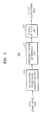
- FIG. 1 is a diagram for describing a method of localizing a multichannel sound signal in the related art.
- a head-related transfer function (HRFT) filter 10 applies sense of elevation corresponding to a predetermined elevation to an input signal.
- the HRFT filter 10 may make an audience feel that an output sound signal is output by a virtual speaker located at the predetermined elevation instead of an actual speaker.
- a signal replicating unit 20 replicates the input signal and generates a multichannel sound signal, whereas a gain value adjusting unit 30 applies a predetermined gain value to the sound signal of each channel and outputs the sound signals.
- An HRTF which is included in the HRFT filter 10 and is applied to the input signal, is a generalized HRTF indicating information regarding paths from an actual speaker to the ears of an audience. Therefore, a method of localizing a multichannel sound signal in the related art does not consider an HRTF that varies based on changes of locations of the ears of an audience or a change of an audience. As a result, the sense of elevation of an audience is deteriorated.
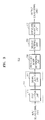
- FIG. 2 is a block diagram showing the configuration of a multichannel sound signal localizing apparatus 200 according to an embodiment of the present invention.
- the multichannel sound signal localizing apparatus 200 shown in FIG. 2 may include a multichannel sound signal generating unit 210, a frequency range determining unit 230, and a second filtering unit 250.
- the multichannel sound signal generating unit 210, the frequency range determining unit 230, and the second filtering unit 250 may each be embodied as a microprocessor.
- an input sound signal 205 is input to the multichannel sound signal generating unit 210.
- the input sound signal 205 may include a mono sound signal and a multichannel sound signal.
- the input sound signal 205 may be a signal stored in a memory unit (not shown) or a signal transmitted from an external device (not shown).
- the multichannel sound signal generating unit 210 may generate a multichannel sound signal to which sense of elevation is applied by applying a first filter corresponding to a predetermined elevation to the input sound signal 205.
- the first filter may include an HRFT filter.
- the HRTF includes information regarding paths from a spatial location of sound source to both ears an audience, that is, frequency transmission characteristics.
- the HRTF enables an audience to recognize stereoscopic sounds by using not only simple path differences, such as interaural level difference (ILD) and interaural time difference (ITD) between signals received by both ears, but also phenomenon that characteristics of complicated path, such as diffraction at head surface and reflection by earflap, is changed based on directions in which sound propagates. In each of the directions in a space, HRTF has unique characteristics. Therefore, stereoscopic sounds may be generated by using the HRTF.
- ILD interaural level difference
- ITD interaural time difference
- Equation 1 is an example of the first filter applied to the input sound signal 205 by the multichannel sound signal generating unit 210.
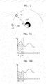
- FIG. 4 is a diagram for describing a first filter in the multichannel sound signal localizing apparatus 200, according to an embodiment of the present invention, where a second HRTF includes an HRTF H2 which indicates information regarding paths from the spatial location of a virtual speaker 450 located at a predetermined elevation ⁇ to the ears of an audience 410., whereas a first HRTF includes an HRTF H1 which indicates information regarding paths from the spatial location of an actual speaker 430 to the ears of the the audience 410. Both the first HRTF and the second HRTF correspond to transfer functions in the frequency domain, and it will be necessary to perform convolution calculation for converting Equation 1 to the time domain.
- the virtual speaker 450 refers to a virtual speaker that is recognized as an unreal speaker outputting sound signals to which sense of elevation is applied.
- the second HRTF corresponding to a predetermined elevation ⁇ is divided by the first HRTF corresponding to a horizontal surface (or elevation of the actual speaker 430).
- An optimal HRTF corresponding to the predetermined elevation ⁇ varies from person to person. Therefore, it is preferable to calculate and apply an HRTF for each person, but it is impossible. Therefore, after calculating an HRTF for a part of people in a group having similar characteristics (e.g., physical characteristics such as age and elevation or preference characteristics such as preferred frequency bands and preferred genre of music), a representative value (e.g., an average value) may be determined as the HRTF to be applied to all people in the group.
- the second HRTF and the first HRTF in Equation 1 are generalized HRTFs corresponding to a predetermined elevation.
- the multichannel sound signal generating unit 210 may select a suitable second HRTF based on a location at which a virtual sound source is to be localized (that is, an elevation angle).
- the multichannel sound signal generating unit 210 may select a second HRTF corresponding to a virtual sound source by using mapping information between location of the virtual sound source and the HRTF.
- Information regarding the location of the virtual sound source may be received via a (software or hardware) module, such as an application, or may be input by a user.
- the frequency range determining unit 230 determines a frequency range frequency range of a dynamic cue according to change of an HRTF indicating information regarding paths from the spatial location of an actual speaker to the ears of an audience.
- the first HRTF and the second HRTF included in the first filter are generalized HRTFs. Therefore, when locations of the ears of an audience change as the audience move their head or the audience moves, information regarding paths from the spatial location of the actual speaker to the ears of the audience is also changed. As a result, it is difficult for the audience to receive a sense of elevation from the output sound signal 295 due to the dynamic cue based on factors including the change of the locations of the ears of the audience.
- the cue refers to the basis for receiving a sense of elevation of the output sound signal 295 (e.g., spectrum peaks and notches of sound pressure reaching the eardrums via which an audience recognizes sense of elevation). Therefore, if the basis is changed, the audience is unable to receive the sense of elevation of the output sound signal 295.
- FIG. 5 is a diagram for describing a frequency range of a dynamic cue.
- FIG. 5(a) is a graph showing a magnitude M of a generalized first HRTF, which indicates information regarding paths from the spatial location of an actual speaker to the ears of an audience, in the frequency f domain
- FIG. 5(b) is a graph showing a magnitude M of a changed HRTF, which indicates information regarding paths from the spatial location of an actual speaker to the ears of an audience and is changed due to changes of the locations of the ears of the audience, in the frequency f domain.
- the magnitude M of an HRTF signal in the L section is changed due to factors including changes of the locations of the ears of the audience.
- the audience may be unable to receive a sense of elevation of the output sound signal 295 due to the change of the HRTF in the L section.
- the L section may be determined in any of various manners. For example, the L section may be determined by comparing an HRTF at a first elevation to HRTFs at second elevations that are very close to the first elevation. Alternatively, the L section may be determined by comparing the HRTF at the first elevation to an HRTF corresponding to locations of the ears of an audience.
- the second filtering unit 250 may apply a second filter to a sound signal of at least one channel from among a multichannel sound signal to which the first filter is applied.
- the multichannel sound signal localizing apparatus 200 may further include an output unit which outputs a multichannel sound signal to which the second filter is applied.
- a signal from among the multichannel sound signal to which the second filter applied, the signal corresponding to a frequency range of a dynamic cue may be changed to remove or reduce the dynamic cue.
- a signal corresponding to a frequency range of the dynamic cue is changed in a multichannel sound signal to remove or reduce the dynamic cue, an audience may receive a realistic sense of elevation even if locations of the ears of the audience change.
- frequency ranges of the dynamic cue are between 800 Hz and 1000 Hz and between 1500 Hz and 2000 Hz
- signals corresponding to the frequency ranges between 800 Hz and 1000 Hz and between 1500 Hz and 2000 Hz from among the output sound signals may be changed for removing the dynamic cue.
- the second filter may include at least one from among a phase inverse filter for inversing a phase of signals included in the frequency ranges of the dynamic cue, an amplitude control filter for reducing amplitudes of signals included in the frequency ranges of the dynamic cue, and a delay filter for delaying the signals included in the frequency ranges of the dynamic cue.
- the second filtering unit 250 may inverse the phase of signals in a left signal or a right signal in the stereo sound signal corresponding to the frequency ranges between 800 Hz and 1000 Hz and between 1500 Hz and 2000 Hz by applying the phase inverse filter to the left signal or the right signal.
- phase of signals in the left signal corresponding to the frequency ranges between 800 Hz and 1000 Hz and between 1500 Hz and 2000 Hz is inversed, when the left signal and the right signal are output by 2-channel speakers, signals in the left signal and the right signal corresponding to the frequency ranges between 800 Hz and 1000 Hz and between 1500 Hz and 2000 Hz are offset at locations of the ears of an audience, and thus the dynamic cue is removed.
- the second filtering unit 250 may remove or reduce the dynamic cue by changing amplitudes of signals from among sound signals of the respective channels of a multichannel sound signal, the signals corresponding to the frequency ranges of the dynamic cue. For example, after signals in a left signal and a right signal in a stereo sound signal corresponding to the frequency ranges between 800 Hz and 1000 Hz and between 1500 Hz and 2000 Hz are divided according to frequency bands, amplitudes of the signals of the respective divided frequency bands may be adjusted to be different in the left signal and the right signals, and thus the dynamic cue may be reduced.
- the dynamic cue may be reduced by adjusting amplitudes of signals from among the sound signals of the respective channels in a multichannel sound signal corresponding to the frequency ranges between 800 Hz and 1000 Hz and between 1500 Hz and 2000 Hz to be close to zero.
- the second filtering unit 250 may apply the delay filter to a left signal or a right signal in the stereo sound signal.
- the dynamic cue may be removed by delaying signals in the left signal corresponding to the frequency ranges between 800 Hz and 1000 Hz and between 1500 Hz and 2000 Hz, wherein the difference between the phase of the signals in the left signal and the phase of signals in the right signal corresponding to the frequency ranges between 800 Hz and 1000 Hz and between 1500 Hz and 2000 Hz is 180°.
- a multichannel sound signal includes signals of 2 or more channels (e.g., 5.1 channels or 7.1 channels)
- dynamic cue may be removed or reduced by using at least one filter from among a phase inverse filter, an amplitude control filter, and a delay filter. Any of various methods for removing or reducing dynamic cue may be employed as long as the methods are obvious to one of ordinary skill in the art.
- FIG. 3 is a block diagram showing the configuration of a multichannel sound signal localizing apparatus 300 according to another embodiment of the present invention.
- the multichannel sound signal localizing apparatus 300 shown in FIG. 3 may include a multichannel sound signal generating unit 310, a frequency range determining unit 330, a second filtering unit 350, and an amplitude adjusting unit 370. Since the frequency range determining unit 330 and the second filtering unit 350 are described above with reference to FIG. 2 , detailed descriptions thereof are omitted.
- the multichannel sound signal generating unit 310 may include a first filtering unit 315 and a signal replicating unit 317.
- the first filtering unit 315 applies a first filter to an input sound signal 305 and a signal replicating unit 317.
- the first filter may include an HRTF filter.
- the signal replicating unit 317 generates a multichannel sound signal by replicating the input sound signal 305 to which the first filter is applied.
- FIG. 3 shows that the first filtering unit 315 is arranged in front of the signal replicating unit 317, the first filtering unit 315 may be arranged after the signal replicating unit 317, and the first filter of first filtering unit 315 is applied to the multichannel sound signal generated by the signal replicating unit 317.
- the signal replicating unit 317 may generate a multichannel sound signal, such as a stereo sound signal, a 5.1 channel sound signal, and a 7.1 channel sound signal, by replicating the mono sound signal.
- the amplitude adjusting unit 370 adjusts amplitudes of sound signals of the respective channels of a multichannel sound signal, such that a virtual speaker is located at a predetermined position on a horizontal surface including the virtual speaker located at a predetermined elevation.
- the multichannel sound signal may be localized on the horizontal surface by adjusting amplitudes of sound signals of the respective channels by applying suitable gain values to the sound signals of the respective channels.
- FIG. 6 is a flowchart showing a method of localizing a multichannel sound signal, according to an embodiment of the present invention.
- the method of localizing a multichannel sound signal includes operations that are performed by the multichannel sound signal localizing apparatus 200 shown in FIG. 2 in chronological order. Therefore, even though omitted below, the descriptions of the multichannel sound signal localizing apparatus 200 shown in FIG. 2 above may also be applied to the method of localizing a multichannel sound signal shown in FIG. 6 .
- the multichannel sound signal localizing apparatus 200 generates a multichannel sound signal to which sense of elevation is applied by applying a first filter corresponding to a predetermined elevation to an input sound signal.
- the input sound signal may include a mono sound signal and a stereo sound signal, where the multichannel sound signal may have more channels than the input sound signal.
- the multichannel sound signal localizing apparatus 200 determines a frequency range of a dynamic cue according to change of an HRTF indicating information regarding paths from the spatial location of an actual speaker to the ears of an audience. Due to the dynamic cue according to the change of the HRTF, the sense of elevation received by an audience from a sound signal output by the speaker is deteriorated.
- the multichannel sound signal localizing apparatus 200 applies a second filter to a sound signal of at least one channel from among the multichannel sound signal.
- a signal in the multichannel sound signal to which the second filter is applied corresponding to the frequency range of the dynamic cue is changed to remove or reduce the dynamic cue.
- the dynamic cue of the multichannel sound signal may be removed by the second filter, and thus a realistic sense of elevation may be provided to an audience.
- the embodiments of the present invention can be written as computer programs and can be implemented in general-use digital computers that execute the programs using a computer readable recording medium.
- Examples of the computer readable recording medium include magnetic storage media (e.g., ROM, floppy disks, hard disks, etc.), optical recording media (e.g., CD-ROMs, or DVDs), etc.
- magnetic storage media e.g., ROM, floppy disks, hard disks, etc.
- optical recording media e.g., CD-ROMs, or DVDs
Landscapes
- Physics & Mathematics (AREA)
- Engineering & Computer Science (AREA)
- Acoustics & Sound (AREA)
- Signal Processing (AREA)
- Stereophonic System (AREA)
Abstract
Description
- This application claims the benefit of
U.S. Provisional Application No. 61/583,309, filed on January 5, 2012 - The present invention relates to a method and an apparatus for localizing a multichannel sound signal, and more particularly, to a method and an apparatus for localizing a multichannel sound signal by applying sense of elevation to the multichannel sound signal.
- Along with the recent developments in multimedia technologies, research is being actively made on the acquisition and reproduction of high-quality audio and video. Particularly, along with the developments in 3-dimensional (3D) stereoscopic imaging technologies, stereoscopic audio technologies are also being focused on.
- From among stereoscopic audio technologies, sound image localization is a technique for localizing a virtual sound image at a location, where no actual speaker is located, for a more realistic audio reproduction.
- The sound image localization may be categorized into horizontal surface sound image localization and vertical surface sound image localization. Here, the vertical surface sound image localization is not as efficient as the horizontal surface sound image localization and developments thereof are relatively subtle. Therefore, there is demand for an efficient technique for vertical surface sound image localization to provide realistic sound to an audience.
- The present invention provides a method and an apparatus for localizing a multichannel sound signal, by which an audience receives a realistic sense of elevation from the multichannel sound signal.
- According to an aspect of the present invention, there is provided a method of localizing a multichannel sound signal, the method including generating a multichannel sound signal to which sense of elevation is applied by applying a first filter, which corresponds to a predetermined elevation, to an input sound signal; determining frequency ranges of a dynamic cue according to change of a head-related transfer function (HRTF) indicating information regarding paths from the spatial location of an actual speaker to the ears of an audience; and applying a second filter to a sound signal of at least one channel in the multichannel sound signal, wherein, when the multichannel sound signal to which the second filter is applied is output, signals in the multichannel sound signal to which the second filter is applied corresponding to the frequency ranges of the dynamic cue are changed to remove or reduce the dynamic cue.
- The generating of the multichannel sound signal includes applying the first filter to an input mono sound signal; and generating the multichannel sound signal to which sense of elevation is applied by replicating the input mono sound signal to which the first filter is applied.
- The first filter is determined from following equation, a second HRTF / a first HRTF, wherein the second HRTF includes an HRTF indicating information regarding paths from the spatial location of a virtual speaker located at the predetermined elevation to the ears of an audience, and the first HRTF includes an HRTF indicating information regarding paths from the spatial location of an actual speaker to the ears of the audience.
- The determining of the frequency ranges of the dynamic cue includes determining frequency ranges in the frequency domain of the HRTF that change in correspondence to changes of locations of the ears of an audience or a change of an audience as the frequency ranges of the dynamic cue.
- The multichannel sound signal includes a stereo sound signal, the second filter includes a phase inverse filter for inversing a phase of signals included in the frequency ranges of the dynamic cue, and wherein the applying of the second filter to the sound signal of the at least one channel in the multichannel sound signal includes applying the phase inverse filter to one sound signal from among the stereo sound signal.
- The second filter includes an amplitude adjusting filter for adjusting amplitudes of signals included in the frequency ranges of the dynamic cue.
- The multichannel sound signal includes a stereo sound signal, the second filter includes a delay filter for delaying signals included in the frequency ranges of the dynamic cue, and wherein the applying of the second filter to the sound signal of the at least one channel in the multichannel sound signal includes applying the delay filter to one sound signal from among the stereo sound signal.
- The method further includes adjusting amplitudes of sound signals of the respective channels in the multichannel sound signal, such that the virtual speaker is located on a predetermined position on a horizontal surface including the virtual speaker at the predetermined elevation.
- According to an aspect of the present invention, there is provided a computer-readable recording medium having recorded thereon a computer program for implementing the method of claim 1.
- According to an aspect of the present invention, there is provided a multichannel sound signal localizing apparatus including a multichannel sound signal generating unit for generating a multichannel sound signal to which sense of elevation is applied by applying a first filter, which corresponds to a predetermined elevation, to an input sound signal; a frequency range determining unit for determining frequency ranges of a dynamic cue according to change of a head-related transfer function (HRTF) indicating information regarding paths from the spatial location of an actual speaker to the ears of an audience; and a second filtering unit for applying a second filter to a sound signal of at least one channel in the multichannel sound signal, wherein, when the multichannel sound signal to which the second filter is applied is output, signals in the multichannel sound signal to which the second filter is applied corresponding to the frequency ranges of the dynamic cue are changed to remove or reduce the dynamic cue.
- The multichannel sound signal generating unit includes a first filtering unit for applying the first filter to an input mono sound signal; and a signal replicating unit for generating the multichannel sound signal to which sense of elevation is applied by replicating the input mono sound signal to which the first filter is applied.
- The first filter is determined from following equation, a second HRTF / a first HRTF, wherein the second HRTF includes an HRTF indicating information regarding paths from the spatial location of a virtual speaker located at the predetermined elevation to the ears of an audience, and the first HRTF includes an HRTF indicating information regarding paths from the spatial location of an actual speaker to the ears of the audience.
- The frequency range determining unit determines frequency ranges in the frequency domain of the HRTF that change in correspondence to changes of locations of the ears of an audience or a change of an audience as the frequency ranges of the dynamic cue.
- The multichannel sound signal includes a stereo sound signal, the second filter includes a phase inverse filter for inversing a phase of signals included in the frequency ranges of the dynamic cue, and the second filtering unit applies the phase inverse filter to one sound signal from among the stereo sound signal.
- The second filter includes an amplitude adjusting filter for adjusting amplitudes of signals included in the frequency ranges of the dynamic cue.
- The multichannel sound signal includes a stereo sound signal, the second filter includes a delay filter for delaying signals included in the frequency ranges of the dynamic cue, and the second filtering unit applies the delay filter to one sound signal from among the stereo sound signal.
- The multichannel sound signal localizing apparatus further includes an amplitude adjusting unit for adjusting amplitudes of sound signals of the respective channels in the multichannel sound signal, such that the virtual speaker is located on a predetermined position on a horizontal surface including the virtual speaker at the predetermined elevation.
- The above and other features and advantages of the present invention will become more apparent by describing in detail exemplary embodiments thereof with reference to the attached drawings in which:
-
FIG. 1 is a diagram for describing a method of localizing a multichannel sound signal in the related art; -
FIG. 2 is a block diagram showing the configuration of a multichannel sound signal localizing apparatus according to an embodiment of the present invention; -
FIG. 3 is a block diagram showing the configuration of a multichannel sound signal localizing apparatus according to another embodiment of the present invention; -
FIG. 4 is a diagram for describing a first filter in the multichannel sound signal localizing apparatus, according to an embodiment of the present invention; -
FIG. 5 is a diagram for describing frequency range of a dynamic cue; and -
FIG. 6 is a flowchart showing a method of localizing a multichannel sound signal, according to an embodiment of the present invention. - The present invention will now be described more fully with reference to the accompanying drawings, in which exemplary embodiments of the invention are shown. The invention may, however, be embodied in many different forms and should not be construed as being limited to the embodiments set forth herein; rather, these embodiments are provided so that this disclosure will be thorough and complete, and will fully convey the concept of the invention to those skilled in the art. Like reference numerals in the drawings denote like elements.
- A term "unit", that is, "module", used in the exemplary embodiment means software components or hardware components such as FPGA and ASIC. Also, the module performs predetermined functions. However, the module or unit is not limited to software or hardware. The module can be formed such that the module is stored in addressable recording media. Also, the module can be formed such that one or more processes are executed. For example, the module includes components, such as software components, object-oriented software components, class components, and task components, processes, functions, attributes, procedures, subroutines, segments of program codes, drivers, firmware, micro-code, circuits, data, databases, data formats, tables, arrays, and variables. Herein, functions provided by the above components and modules can be achieved with a smaller number of components and modules by combining components and modules with each other, or can be achieved with a larger number of components and modules by dividing the components and the modules.
-
FIG. 1 is a diagram for describing a method of localizing a multichannel sound signal in the related art. - First, a head-related transfer function (HRFT)
filter 10 applies sense of elevation corresponding to a predetermined elevation to an input signal. TheHRFT filter 10 may make an audience feel that an output sound signal is output by a virtual speaker located at the predetermined elevation instead of an actual speaker. - Next, a
signal replicating unit 20 replicates the input signal and generates a multichannel sound signal, whereas a gainvalue adjusting unit 30 applies a predetermined gain value to the sound signal of each channel and outputs the sound signals. - An HRTF, which is included in the
HRFT filter 10 and is applied to the input signal, is a generalized HRTF indicating information regarding paths from an actual speaker to the ears of an audience. Therefore, a method of localizing a multichannel sound signal in the related art does not consider an HRTF that varies based on changes of locations of the ears of an audience or a change of an audience. As a result, the sense of elevation of an audience is deteriorated. -
FIG. 2 is a block diagram showing the configuration of a multichannel soundsignal localizing apparatus 200 according to an embodiment of the present invention. - Referring to
FIG. 2 , the multichannel soundsignal localizing apparatus 200 shown inFIG. 2 may include a multichannel soundsignal generating unit 210, a frequencyrange determining unit 230, and asecond filtering unit 250. The multichannel soundsignal generating unit 210, the frequencyrange determining unit 230, and thesecond filtering unit 250 may each be embodied as a microprocessor. - First, an
input sound signal 205 is input to the multichannel soundsignal generating unit 210. Theinput sound signal 205 may include a mono sound signal and a multichannel sound signal. Theinput sound signal 205 may be a signal stored in a memory unit (not shown) or a signal transmitted from an external device (not shown). - The multichannel sound
signal generating unit 210 may generate a multichannel sound signal to which sense of elevation is applied by applying a first filter corresponding to a predetermined elevation to theinput sound signal 205. In detail, the first filter may include an HRFT filter. - The HRTF includes information regarding paths from a spatial location of sound source to both ears an audience, that is, frequency transmission characteristics. The HRTF enables an audience to recognize stereoscopic sounds by using not only simple path differences, such as interaural level difference (ILD) and interaural time difference (ITD) between signals received by both ears, but also phenomenon that characteristics of complicated path, such as diffraction at head surface and reflection by earflap, is changed based on directions in which sound propagates. In each of the directions in a space, HRTF has unique characteristics. Therefore, stereoscopic sounds may be generated by using the HRTF.
- Equation 1 below is an example of the first filter applied to the
input sound signal 205 by the multichannel soundsignal generating unit 210.
-
FIG. 4 is a diagram for describing a first filter in the multichannel soundsignal localizing apparatus 200, according to an embodiment of the present invention, where a second HRTF includes an HRTF H2 which indicates information regarding paths from the spatial location of avirtual speaker 450 located at a predetermined elevation θ to the ears of an audience 410., whereas a first HRTF includes an HRTF H1 which indicates information regarding paths from the spatial location of anactual speaker 430 to the ears of the theaudience 410. Both the first HRTF and the second HRTF correspond to transfer functions in the frequency domain, and it will be necessary to perform convolution calculation for converting Equation 1 to the time domain. Thevirtual speaker 450 refers to a virtual speaker that is recognized as an unreal speaker outputting sound signals to which sense of elevation is applied. - Since an output sound signal 295 heard by the
audience 410 is output by theactual speaker 430, to make theaudience 410 sense that theoutput sound signal 295 is output by thevirtual speaker 450, the second HRTF corresponding to a predetermined elevation θ is divided by the first HRTF corresponding to a horizontal surface (or elevation of the actual speaker 430). - An optimal HRTF corresponding to the predetermined elevation θ varies from person to person. Therefore, it is preferable to calculate and apply an HRTF for each person, but it is impossible. Therefore, after calculating an HRTF for a part of people in a group having similar characteristics (e.g., physical characteristics such as age and elevation or preference characteristics such as preferred frequency bands and preferred genre of music), a representative value (e.g., an average value) may be determined as the HRTF to be applied to all people in the group. In other words, the second HRTF and the first HRTF in Equation 1 are generalized HRTFs corresponding to a predetermined elevation.
- The multichannel sound
signal generating unit 210 may select a suitable second HRTF based on a location at which a virtual sound source is to be localized (that is, an elevation angle). The multichannel soundsignal generating unit 210 may select a second HRTF corresponding to a virtual sound source by using mapping information between location of the virtual sound source and the HRTF. Information regarding the location of the virtual sound source may be received via a (software or hardware) module, such as an application, or may be input by a user. - The frequency
range determining unit 230 determines a frequency range frequency range of a dynamic cue according to change of an HRTF indicating information regarding paths from the spatial location of an actual speaker to the ears of an audience. - As described above, the first HRTF and the second HRTF included in the first filter are generalized HRTFs. Therefore, when locations of the ears of an audience change as the audience move their head or the audience moves, information regarding paths from the spatial location of the actual speaker to the ears of the audience is also changed. As a result, it is difficult for the audience to receive a sense of elevation from the
output sound signal 295 due to the dynamic cue based on factors including the change of the locations of the ears of the audience. The cue refers to the basis for receiving a sense of elevation of the output sound signal 295 (e.g., spectrum peaks and notches of sound pressure reaching the eardrums via which an audience recognizes sense of elevation). Therefore, if the basis is changed, the audience is unable to receive the sense of elevation of theoutput sound signal 295. -
FIG. 5 is a diagram for describing a frequency range of a dynamic cue. -
FIG. 5(a) is a graph showing a magnitude M of a generalized first HRTF, which indicates information regarding paths from the spatial location of an actual speaker to the ears of an audience, in the frequency f domain, whereasFIG. 5(b) is a graph showing a magnitude M of a changed HRTF, which indicates information regarding paths from the spatial location of an actual speaker to the ears of an audience and is changed due to changes of the locations of the ears of the audience, in the frequency f domain. - Referring to
FIGS. 5(a) and 5(b) , in the HRTF in the frequency domain, the magnitude M of an HRTF signal in the L section is changed due to factors including changes of the locations of the ears of the audience. In other words, the audience may be unable to receive a sense of elevation of theoutput sound signal 295 due to the change of the HRTF in the L section. - The L section may be determined in any of various manners. For example, the L section may be determined by comparing an HRTF at a first elevation to HRTFs at second elevations that are very close to the first elevation. Alternatively, the L section may be determined by comparing the HRTF at the first elevation to an HRTF corresponding to locations of the ears of an audience.
- The
second filtering unit 250 may apply a second filter to a sound signal of at least one channel from among a multichannel sound signal to which the first filter is applied. Although not shown inFIG. 2 , the multichannel soundsignal localizing apparatus 200 may further include an output unit which outputs a multichannel sound signal to which the second filter is applied. - In a case where a multichannel sound signal to which the second filter is applied is output, a signal from among the multichannel sound signal to which the second filter applied, the signal corresponding to a frequency range of a dynamic cue, may be changed to remove or reduce the dynamic cue. When a signal corresponding to a frequency range of the dynamic cue is changed in a multichannel sound signal to remove or reduce the dynamic cue, an audience may receive a realistic sense of elevation even if locations of the ears of the audience change.
- For example, if frequency ranges of the dynamic cue are between 800 Hz and 1000 Hz and between 1500 Hz and 2000 Hz, when sound signals of the respective channels included in a multichannel sound signal are output by a speaker, signals corresponding to the frequency ranges between 800 Hz and 1000 Hz and between 1500 Hz and 2000 Hz from among the output sound signals may be changed for removing the dynamic cue.
- The second filter may include at least one from among a phase inverse filter for inversing a phase of signals included in the frequency ranges of the dynamic cue, an amplitude control filter for reducing amplitudes of signals included in the frequency ranges of the dynamic cue, and a delay filter for delaying the signals included in the frequency ranges of the dynamic cue.
- If the second filter is a phase inverse filter and the multichannel sound signal is a stereo sound signal, the
second filtering unit 250 may inverse the phase of signals in a left signal or a right signal in the stereo sound signal corresponding to the frequency ranges between 800 Hz and 1000 Hz and between 1500 Hz and 2000 Hz by applying the phase inverse filter to the left signal or the right signal. If the phase of signals in the left signal corresponding to the frequency ranges between 800 Hz and 1000 Hz and between 1500 Hz and 2000 Hz is inversed, when the left signal and the right signal are output by 2-channel speakers, signals in the left signal and the right signal corresponding to the frequency ranges between 800 Hz and 1000 Hz and between 1500 Hz and 2000 Hz are offset at locations of the ears of an audience, and thus the dynamic cue is removed. - Furthermore, if the second filter is an amplitude control filter, the
second filtering unit 250 may remove or reduce the dynamic cue by changing amplitudes of signals from among sound signals of the respective channels of a multichannel sound signal, the signals corresponding to the frequency ranges of the dynamic cue. For example, after signals in a left signal and a right signal in a stereo sound signal corresponding to the frequency ranges between 800 Hz and 1000 Hz and between 1500 Hz and 2000 Hz are divided according to frequency bands, amplitudes of the signals of the respective divided frequency bands may be adjusted to be different in the left signal and the right signals, and thus the dynamic cue may be reduced. Alternatively, the dynamic cue may be reduced by adjusting amplitudes of signals from among the sound signals of the respective channels in a multichannel sound signal corresponding to the frequency ranges between 800 Hz and 1000 Hz and between 1500 Hz and 2000 Hz to be close to zero. - Furthermore, if the second filter is a delay filter and the multichannel sound signal is a stereo sound signal, the
second filtering unit 250 may apply the delay filter to a left signal or a right signal in the stereo sound signal. For example, the dynamic cue may be removed by delaying signals in the left signal corresponding to the frequency ranges between 800 Hz and 1000 Hz and between 1500 Hz and 2000 Hz, wherein the difference between the phase of the signals in the left signal and the phase of signals in the right signal corresponding to the frequency ranges between 800 Hz and 1000 Hz and between 1500 Hz and 2000 Hz is 180°. - If a multichannel sound signal includes signals of 2 or more channels (e.g., 5.1 channels or 7.1 channels), dynamic cue may be removed or reduced by using at least one filter from among a phase inverse filter, an amplitude control filter, and a delay filter. Any of various methods for removing or reducing dynamic cue may be employed as long as the methods are obvious to one of ordinary skill in the art.
-
FIG. 3 is a block diagram showing the configuration of a multichannel soundsignal localizing apparatus 300 according to another embodiment of the present invention. - Referring to
FIG. 3 , the multichannel soundsignal localizing apparatus 300 shown inFIG. 3 may include a multichannel soundsignal generating unit 310, a frequencyrange determining unit 330, asecond filtering unit 350, and anamplitude adjusting unit 370. Since the frequencyrange determining unit 330 and thesecond filtering unit 350 are described above with reference toFIG. 2 , detailed descriptions thereof are omitted. - The multichannel sound
signal generating unit 310 may include afirst filtering unit 315 and asignal replicating unit 317. Thefirst filtering unit 315 applies a first filter to aninput sound signal 305 and asignal replicating unit 317. The first filter may include an HRTF filter. Thesignal replicating unit 317 generates a multichannel sound signal by replicating theinput sound signal 305 to which the first filter is applied. AlthoughFIG. 3 shows that thefirst filtering unit 315 is arranged in front of thesignal replicating unit 317, thefirst filtering unit 315 may be arranged after thesignal replicating unit 317, and the first filter offirst filtering unit 315 is applied to the multichannel sound signal generated by thesignal replicating unit 317. - If the
input sound signal 305 is a mono signal, thesignal replicating unit 317 may generate a multichannel sound signal, such as a stereo sound signal, a 5.1 channel sound signal, and a 7.1 channel sound signal, by replicating the mono sound signal. - The
amplitude adjusting unit 370 adjusts amplitudes of sound signals of the respective channels of a multichannel sound signal, such that a virtual speaker is located at a predetermined position on a horizontal surface including the virtual speaker located at a predetermined elevation. To localize a multichannel sound signal, which is localized to a predetermined elevation , in a predetermined direction on the horizontal surface at the predetermined elevation, the multichannel sound signal may be localized on the horizontal surface by adjusting amplitudes of sound signals of the respective channels by applying suitable gain values to the sound signals of the respective channels. As a result, an audience may receive not only a sense of elevation, but also a directional impression from an output sound signal 395 output by a speaker. -
FIG. 6 is a flowchart showing a method of localizing a multichannel sound signal, according to an embodiment of the present invention. Referring toFIG. 6 , the method of localizing a multichannel sound signal, according to another embodiment of the present invention, includes operations that are performed by the multichannel soundsignal localizing apparatus 200 shown inFIG. 2 in chronological order. Therefore, even though omitted below, the descriptions of the multichannel soundsignal localizing apparatus 200 shown inFIG. 2 above may also be applied to the method of localizing a multichannel sound signal shown inFIG. 6 . - First, in operation S610, the multichannel sound
signal localizing apparatus 200 generates a multichannel sound signal to which sense of elevation is applied by applying a first filter corresponding to a predetermined elevation to an input sound signal. The input sound signal may include a mono sound signal and a stereo sound signal, where the multichannel sound signal may have more channels than the input sound signal. - In operation S620, the multichannel sound
signal localizing apparatus 200 determines a frequency range of a dynamic cue according to change of an HRTF indicating information regarding paths from the spatial location of an actual speaker to the ears of an audience. Due to the dynamic cue according to the change of the HRTF, the sense of elevation received by an audience from a sound signal output by the speaker is deteriorated. - In operation S630, the multichannel sound
signal localizing apparatus 200 applies a second filter to a sound signal of at least one channel from among the multichannel sound signal. When a multichannel sound signal to which the second filter is applied is output by a speaker, a signal in the multichannel sound signal to which the second filter is applied corresponding to the frequency range of the dynamic cue is changed to remove or reduce the dynamic cue. In other words, the dynamic cue of the multichannel sound signal may be removed by the second filter, and thus a realistic sense of elevation may be provided to an audience. - The embodiments of the present invention can be written as computer programs and can be implemented in general-use digital computers that execute the programs using a computer readable recording medium.
- Examples of the computer readable recording medium include magnetic storage media (e.g., ROM, floppy disks, hard disks, etc.), optical recording media (e.g., CD-ROMs, or DVDs), etc.
- While the present invention has been particularly shown and described with reference to exemplary embodiments thereof, it will be understood by those of ordinary skill in the art that various changes in form and details may be made therein without departing from the spirit and scope of the present invention as defined by the following claims.
Claims (17)
- A method of localizing a multichannel sound signal, the method comprising:generating a multichannel sound signal to which sense of elevation is applied by applying a first filter, which corresponds to a predetermined elevation, to an input sound signal;determining frequency ranges of a dynamic cue according to change of a head-related transfer function (HRTF) indicating information regarding paths from the spatial location of an actual speaker to the ears of an audience; andapplying a second filter to a sound signal of at least one channel in the multichannel sound signal,wherein, when the multichannel sound signal to which the second filter is applied is output, signals in the multichannel sound signal to which the second filter is applied corresponding to the frequency ranges of the dynamic cue are changed to remove or reduce the dynamic cue.
- The method of claim 1, wherein the generating of the multichannel sound signal comprises:applying the first filter to an input mono sound signal; andgenerating the multichannel sound signal to which sense of elevation is applied by replicating the input mono sound signal to which the first filter is applied.
- The method of claim 1, wherein the first filter is determined from following equation,

wherein the second HRTF includes an HRTF indicating information regarding paths from the spatial location of a virtual speaker located at the predetermined elevation to the ears of an audience, and
the first HRTF includes an HRTF indicating information regarding paths from the spatial location of an actual speaker to the ears of the audience. - The method of claim 1, wherein the determining of the frequency ranges of the dynamic cue comprises determining frequency ranges in the frequency domain of the HRTF that change in correspondence to changes of locations of the ears of an audience or a change of an audience as the frequency ranges of the dynamic cue.
- The method of claim 1, wherein the multichannel sound signal comprises a stereo sound signal,
the second filter comprises a phase inverse filter for inversing a phase of signals included in the frequency ranges of the dynamic cue, and
wherein the applying of the second filter to the sound signal of the at least one channel in the multichannel sound signal comprises applying the phase inverse filter to one sound signal from among the stereo sound signal. - The method of claim 1, wherein the second filter comprises an amplitude adjusting filter for adjusting amplitudes of signals included in the frequency ranges of the dynamic cue.
- The method of claim 1, wherein the multichannel sound signal comprises a stereo sound signal,
the second filter comprises a delay filter for delaying signals included in the frequency ranges of the dynamic cue, and
wherein the applying of the second filter to the sound signal of the at least one channel in the multichannel sound signal comprises applying the delay filter to one sound signal from among the stereo sound signal. - The method of claim 1, further comprising adjusting amplitudes of sound signals of the respective channels in the multichannel sound signal, such that the virtual speaker is located on a predetermined position on a horizontal surface including the virtual speaker at the predetermined elevation.
- A computer-readable recording medium having recorded thereon a computer program for implementing the method of claim 1.
- A multichannel sound signal localizing apparatus comprising:a multichannel sound signal generating unit for generating a multichannel sound signal to which sense of elevation is applied by applying a first filter, which corresponds to a predetermined elevation, to an input sound signal;a frequency range determining unit for determining frequency ranges of a dynamic cue according to change of a head-related transfer function (HRTF) indicating information regarding paths from the spatial location of an actual speaker to the ears of an audience; anda second filtering unit for applying a second filter to a sound signal of at least one channel in the multichannel sound signal,wherein, when the multichannel sound signal to which the second filter is applied is output, signals in the multichannel sound signal to which the second filter is applied corresponding to the frequency ranges of the dynamic cue are changed to remove or reduce the dynamic cue.
- The multichannel sound signal localizing apparatus of claim 10, wherein the multichannel sound signal generating unit comprises:a first filtering unit for applying the first filter to an input mono sound signal; anda signal replicating unit for generating the multichannel sound signal to which sense of elevation is applied by replicating the input mono sound signal to which the first filter is applied.
- The multichannel sound signal localizing apparatus of claim 10, wherein the first filter is determined from following equation,

wherein the second HRTF includes an HRTF indicating information regarding paths from the spatial location of a virtual speaker located at the predetermined elevation to the ears of an audience, and
the first HRTF includes an HRTF indicating information regarding paths from the spatial location of an actual speaker to the ears of the audience. - The multichannel sound signal localizing apparatus of claim 10, wherein the frequency range determining unit determines frequency ranges in the frequency domain of the HRTF that change in correspondence to changes of locations of the ears of an audience or a change of an audience as the frequency ranges of the dynamic cue.
- The multichannel sound signal localizing apparatus of claim 10, wherein the multichannel sound signal comprises a stereo sound signal,
the second filter comprises a phase inverse filter for inversing a phase of signals included in the frequency ranges of the dynamic cue, and
the second filtering unit applies the phase inverse filter to one sound signal from among the stereo sound signal. - The multichannel sound signal localizing apparatus of claim 10, wherein the second filter comprises an amplitude adjusting filter for adjusting amplitudes of signals included in the frequency ranges of the dynamic cue.
- The multichannel sound signal localizing apparatus of claim 10, wherein the multichannel sound signal comprises a stereo sound signal,
the second filter comprises a delay filter for delaying signals included in the frequency ranges of the dynamic cue, and
the second filtering unit applies the delay filter to one sound signal from among the stereo sound signal. - The multichannel sound signal localizing apparatus of claim 10, further comprising an amplitude adjusting unit for adjusting amplitudes of sound signals of the respective channels in the multichannel sound signal, such that the virtual speaker is located on a predetermined position on a horizontal surface including the virtual speaker at the predetermined elevation.
Applications Claiming Priority (2)
| Application Number | Priority Date | Filing Date | Title |
|---|---|---|---|
| US201261583309P | 2012-01-05 | 2012-01-05 | |
| PCT/KR2013/000047 WO2013103256A1 (en) | 2012-01-05 | 2013-01-04 | Method and device for localizing multichannel audio signal |
Publications (2)
| Publication Number | Publication Date |
|---|---|
| EP2802161A1 true EP2802161A1 (en) | 2014-11-12 |
| EP2802161A4 EP2802161A4 (en) | 2015-12-23 |
Family
ID=48745287
Family Applications (1)
| Application Number | Title | Priority Date | Filing Date |
|---|---|---|---|
| EP13733650.9A Ceased EP2802161A4 (en) | 2012-01-05 | 2013-01-04 | METHOD AND DEVICE FOR LOCATING A MULTICANAL AUDIO SIGNAL |
Country Status (4)
| Country | Link |
|---|---|
| US (1) | US11445317B2 (en) |
| EP (1) | EP2802161A4 (en) |
| KR (1) | KR102160248B1 (en) |
| WO (1) | WO2013103256A1 (en) |
Cited By (1)
| Publication number | Priority date | Publication date | Assignee | Title |
|---|---|---|---|---|
| WO2017072118A1 (en) * | 2015-10-26 | 2017-05-04 | Fraunhofer-Gesellschaft zur Förderung der angewandten Forschung e.V. | Apparatus and method for generating a filtered audio signal realizing elevation rendering |
Families Citing this family (9)
| Publication number | Priority date | Publication date | Assignee | Title |
|---|---|---|---|---|
| RU2676415C1 (en) | 2014-04-11 | 2018-12-28 | Самсунг Электроникс Ко., Лтд. | Method and device for rendering of sound signal and computer readable information media |
| MX365637B (en) | 2014-06-26 | 2019-06-10 | Samsung Electronics Co Ltd | Method and device for rendering acoustic signal, and computer-readable recording medium. |
| US9609436B2 (en) | 2015-05-22 | 2017-03-28 | Microsoft Technology Licensing, Llc | Systems and methods for audio creation and delivery |
| EP3304929B1 (en) * | 2015-10-14 | 2021-07-14 | Huawei Technologies Co., Ltd. | Method and device for generating an elevated sound impression |
| US9591427B1 (en) * | 2016-02-20 | 2017-03-07 | Philip Scott Lyren | Capturing audio impulse responses of a person with a smartphone |
| WO2017192972A1 (en) | 2016-05-06 | 2017-11-09 | Dts, Inc. | Immersive audio reproduction systems |
| US10979844B2 (en) | 2017-03-08 | 2021-04-13 | Dts, Inc. | Distributed audio virtualization systems |
| WO2019066348A1 (en) * | 2017-09-28 | 2019-04-04 | 가우디오디오랩 주식회사 | Audio signal processing method and device |
| GB2620796A (en) * | 2022-07-22 | 2024-01-24 | Sony Interactive Entertainment Europe Ltd | Methods and systems for simulating perception of a sound source |
Family Cites Families (21)
| Publication number | Priority date | Publication date | Assignee | Title |
|---|---|---|---|---|
| US6307941B1 (en) * | 1997-07-15 | 2001-10-23 | Desper Products, Inc. | System and method for localization of virtual sound |
| KR19990041134A (en) * | 1997-11-21 | 1999-06-15 | 윤종용 | 3D sound system and 3D sound implementation method using head related transfer function |
| US6504934B1 (en) * | 1998-01-23 | 2003-01-07 | Onkyo Corporation | Apparatus and method for localizing sound image |
| GB2351213B (en) | 1999-05-29 | 2003-08-27 | Central Research Lab Ltd | A method of modifying one or more original head related transfer functions |
| US7231054B1 (en) * | 1999-09-24 | 2007-06-12 | Creative Technology Ltd | Method and apparatus for three-dimensional audio display |
| US8054980B2 (en) * | 2003-09-05 | 2011-11-08 | Stmicroelectronics Asia Pacific Pte, Ltd. | Apparatus and method for rendering audio information to virtualize speakers in an audio system |
| KR100677119B1 (en) | 2004-06-04 | 2007-02-02 | 삼성전자주식회사 | Wide stereo playback method and device |
| ATE533315T1 (en) * | 2004-09-16 | 2011-11-15 | Panasonic Corp | ARRANGEMENT FOR SOUND IMAGE LOCALIZATION |
| EP1761110A1 (en) | 2005-09-02 | 2007-03-07 | Ecole Polytechnique Fédérale de Lausanne | Method to generate multi-channel audio signals from stereo signals |
| US8027477B2 (en) * | 2005-09-13 | 2011-09-27 | Srs Labs, Inc. | Systems and methods for audio processing |
| JP4821250B2 (en) * | 2005-10-11 | 2011-11-24 | ヤマハ株式会社 | Sound image localization device |
| KR100739798B1 (en) | 2005-12-22 | 2007-07-13 | 삼성전자주식회사 | Method and apparatus for reproducing a virtual sound of two channels based on the position of listener |
| EP2328364B1 (en) * | 2006-10-13 | 2020-07-01 | Auro Technologies NV | A method and encoder for combining digital data sets, a decoding method and decoder for such combined digital data sets and a record carrier for storing such combined digital data set |
| US20080253577A1 (en) * | 2007-04-13 | 2008-10-16 | Apple Inc. | Multi-channel sound panner |
| KR100971700B1 (en) * | 2007-11-07 | 2010-07-22 | 한국전자통신연구원 | Spatial cue-based binaural stereo synthesizing apparatus and method thereof, and binaural stereo decoding apparatus using the same |
| TWI559786B (en) * | 2008-09-03 | 2016-11-21 | 杜比實驗室特許公司 | Enhancing the reproduction of multiple audio channels |
| EP2175670A1 (en) | 2008-10-07 | 2010-04-14 | Fraunhofer-Gesellschaft zur Förderung der angewandten Forschung e.V. | Binaural rendering of a multi-channel audio signal |
| KR101496760B1 (en) * | 2008-12-29 | 2015-02-27 | 삼성전자주식회사 | Surround sound virtualization methods and devices |
| JP5499513B2 (en) * | 2009-04-21 | 2014-05-21 | ソニー株式会社 | Sound processing apparatus, sound image localization processing method, and sound image localization processing program |
| KR101673232B1 (en) * | 2010-03-11 | 2016-11-07 | 삼성전자주식회사 | Apparatus and method for producing vertical direction virtual channel |
| KR20120004909A (en) * | 2010-07-07 | 2012-01-13 | 삼성전자주식회사 | Stereo playback method and apparatus |
-
2013
- 2013-01-04 WO PCT/KR2013/000047 patent/WO2013103256A1/en not_active Ceased
- 2013-01-04 KR KR1020130001218A patent/KR102160248B1/en not_active Expired - Fee Related
- 2013-01-04 EP EP13733650.9A patent/EP2802161A4/en not_active Ceased
-
2014
- 2014-07-07 US US14/324,740 patent/US11445317B2/en active Active
Cited By (3)
| Publication number | Priority date | Publication date | Assignee | Title |
|---|---|---|---|---|
| WO2017072118A1 (en) * | 2015-10-26 | 2017-05-04 | Fraunhofer-Gesellschaft zur Förderung der angewandten Forschung e.V. | Apparatus and method for generating a filtered audio signal realizing elevation rendering |
| US10433098B2 (en) * | 2015-10-26 | 2019-10-01 | Fraunhofer-Gesellschaft Zur Foerderung Der Angewandten Forschung E.V. | Apparatus and method for generating a filtered audio signal realizing elevation rendering |
| RU2717895C2 (en) * | 2015-10-26 | 2020-03-27 | Фраунхофер-Гезелльшафт Цур Фердерунг Дер Ангевандтен Форшунг Е.Ф. | Apparatus and method for generating filtered audio signal realizing angle elevation rendering |
Also Published As
| Publication number | Publication date |
|---|---|
| US20140334626A1 (en) | 2014-11-13 |
| US11445317B2 (en) | 2022-09-13 |
| KR20130080819A (en) | 2013-07-15 |
| EP2802161A4 (en) | 2015-12-23 |
| KR102160248B1 (en) | 2020-09-25 |
| WO2013103256A1 (en) | 2013-07-11 |
Similar Documents
| Publication | Publication Date | Title |
|---|---|---|
| AU2018236694B2 (en) | Audio providing apparatus and audio providing method | |
| US11445317B2 (en) | Method and apparatus for localizing multichannel sound signal | |
| US9749767B2 (en) | Method and apparatus for reproducing stereophonic sound | |
| KR101283741B1 (en) | A method and an audio spatial environment engine for converting from n channel audio system to m channel audio system | |
| KR102160254B1 (en) | Method and apparatus for 3D sound reproducing using active downmix | |
| US9191763B2 (en) | Method for headphone reproduction, a headphone reproduction system, a computer program product | |
| CN113950845B (en) | concave audio rendering | |
| EP2645749B1 (en) | Audio apparatus and method of converting audio signal thereof | |
| WO2012042905A1 (en) | Sound reproduction device and sound reproduction method | |
| MX2012010761A (en) | Method and apparatus for reproducing three-dimensional sound. | |
| CN103493513A (en) | Method and system for upmixing audio to generate 3D audio | |
| US9462405B2 (en) | Apparatus and method for generating panoramic sound | |
| EP3700233A1 (en) | Transfer function generation system and method | |
| Jot et al. | Efficient structures for virtual immersive audio processing | |
| KR20100084332A (en) | 3d audio localization method and device and the recording media storing the program performing the said method | |
| Jot et al. | Efficient Structures for Virtual Multi-Channel Immersive Audio Rendering |
Legal Events
| Date | Code | Title | Description |
|---|---|---|---|
| PUAI | Public reference made under article 153(3) epc to a published international application that has entered the european phase |
Free format text: ORIGINAL CODE: 0009012 |
|
| 17P | Request for examination filed |
Effective date: 20140731 |
|
| AK | Designated contracting states |
Kind code of ref document: A1 Designated state(s): AL AT BE BG CH CY CZ DE DK EE ES FI FR GB GR HR HU IE IS IT LI LT LU LV MC MK MT NL NO PL PT RO RS SE SI SK SM TR |
|
| DAX | Request for extension of the european patent (deleted) | ||
| RA4 | Supplementary search report drawn up and despatched (corrected) |
Effective date: 20151125 |
|
| RIC1 | Information provided on ipc code assigned before grant |
Ipc: H04S 5/00 20060101ALI20151119BHEP Ipc: H04S 3/00 20060101ALN20151119BHEP Ipc: H04S 1/00 20060101ALN20151119BHEP Ipc: H04S 7/00 20060101AFI20151119BHEP |
|
| R17P | Request for examination filed (corrected) |
Effective date: 20140731 |
|
| 17Q | First examination report despatched |
Effective date: 20170928 |
|
| REG | Reference to a national code |
Ref country code: DE Ref legal event code: R003 |
|
| STAA | Information on the status of an ep patent application or granted ep patent |
Free format text: STATUS: THE APPLICATION HAS BEEN REFUSED |
|
| 18R | Application refused |
Effective date: 20190527 |