EP2802037A1 - Small loop antenna with shorting conductors for hearing assistance devices - Google Patents
Small loop antenna with shorting conductors for hearing assistance devices Download PDFInfo
- Publication number
- EP2802037A1 EP2802037A1 EP14166610.7A EP14166610A EP2802037A1 EP 2802037 A1 EP2802037 A1 EP 2802037A1 EP 14166610 A EP14166610 A EP 14166610A EP 2802037 A1 EP2802037 A1 EP 2802037A1
- Authority
- EP
- European Patent Office
- Prior art keywords
- antenna
- conductors
- hearing aid
- hearing
- subject matter
- Prior art date
- Legal status (The legal status is an assumption and is not a legal conclusion. Google has not performed a legal analysis and makes no representation as to the accuracy of the status listed.)
- Granted
Links
Images



Classifications
-
- H—ELECTRICITY
- H04—ELECTRIC COMMUNICATION TECHNIQUE
- H04R—LOUDSPEAKERS, MICROPHONES, GRAMOPHONE PICK-UPS OR LIKE ACOUSTIC ELECTROMECHANICAL TRANSDUCERS; ELECTRIC HEARING AIDS; PUBLIC ADDRESS SYSTEMS
- H04R25/00—Electric hearing aids
- H04R25/55—Electric hearing aids using an external connection, either wireless or wired
- H04R25/554—Electric hearing aids using an external connection, either wireless or wired using a wireless connection, e.g. between microphone and amplifier or using Tcoils
-
- H—ELECTRICITY
- H01—ELECTRIC ELEMENTS
- H01Q—ANTENNAS, i.e. RADIO AERIALS
- H01Q1/00—Details of, or arrangements associated with, antennas
- H01Q1/27—Adaptation for use in or on movable bodies
- H01Q1/273—Adaptation for carrying or wearing by persons or animals
-
- H—ELECTRICITY
- H01—ELECTRIC ELEMENTS
- H01Q—ANTENNAS, i.e. RADIO AERIALS
- H01Q1/00—Details of, or arrangements associated with, antennas
- H01Q1/44—Details of, or arrangements associated with, antennas using equipment having another main function to serve additionally as an antenna, e.g. means for giving an antenna an aesthetic aspect
-
- H—ELECTRICITY
- H01—ELECTRIC ELEMENTS
- H01Q—ANTENNAS, i.e. RADIO AERIALS
- H01Q5/00—Arrangements for simultaneous operation of antennas on two or more different wavebands, e.g. dual-band or multi-band arrangements
- H01Q5/30—Arrangements for providing operation on different wavebands
- H01Q5/307—Individual or coupled radiating elements, each element being fed in an unspecified way
- H01Q5/342—Individual or coupled radiating elements, each element being fed in an unspecified way for different propagation modes
- H01Q5/357—Individual or coupled radiating elements, each element being fed in an unspecified way for different propagation modes using a single feed point
- H01Q5/364—Creating multiple current paths
-
- H—ELECTRICITY
- H01—ELECTRIC ELEMENTS
- H01Q—ANTENNAS, i.e. RADIO AERIALS
- H01Q7/00—Loop antennas with a substantially uniform current distribution around the loop and having a directional radiation pattern in a plane perpendicular to the plane of the loop
-
- H—ELECTRICITY
- H04—ELECTRIC COMMUNICATION TECHNIQUE
- H04R—LOUDSPEAKERS, MICROPHONES, GRAMOPHONE PICK-UPS OR LIKE ACOUSTIC ELECTROMECHANICAL TRANSDUCERS; ELECTRIC HEARING AIDS; PUBLIC ADDRESS SYSTEMS
- H04R2225/00—Details of deaf aids covered by H04R25/00, not provided for in any of its subgroups
- H04R2225/49—Reducing the effects of electromagnetic noise on the functioning of hearing aids, by, e.g. shielding, signal processing adaptation, selective (de)activation of electronic parts in hearing aid
-
- H—ELECTRICITY
- H04—ELECTRIC COMMUNICATION TECHNIQUE
- H04R—LOUDSPEAKERS, MICROPHONES, GRAMOPHONE PICK-UPS OR LIKE ACOUSTIC ELECTROMECHANICAL TRANSDUCERS; ELECTRIC HEARING AIDS; PUBLIC ADDRESS SYSTEMS
- H04R2225/00—Details of deaf aids covered by H04R25/00, not provided for in any of its subgroups
- H04R2225/51—Aspects of antennas or their circuitry in or for hearing aids
-
- Y—GENERAL TAGGING OF NEW TECHNOLOGICAL DEVELOPMENTS; GENERAL TAGGING OF CROSS-SECTIONAL TECHNOLOGIES SPANNING OVER SEVERAL SECTIONS OF THE IPC; TECHNICAL SUBJECTS COVERED BY FORMER USPC CROSS-REFERENCE ART COLLECTIONS [XRACs] AND DIGESTS
- Y10—TECHNICAL SUBJECTS COVERED BY FORMER USPC
- Y10T—TECHNICAL SUBJECTS COVERED BY FORMER US CLASSIFICATION
- Y10T29/00—Metal working
- Y10T29/49—Method of mechanical manufacture
- Y10T29/49002—Electrical device making
- Y10T29/49016—Antenna or wave energy "plumbing" making
Definitions
- This document relates generally to hearing assistance systems and more particularly to methods and apparatus for small loop antennas with shorting conductors for hearing assistance devices.
- Modern hearing assistance devices such as hearing aids, are electronic instruments worn in or around the ear that compensate for hearing losses by specially amplifying sound.
- Some hearing aids include an antenna for radio frequency communications.
- Wearers of hearing aids can experience problems with antenna communication. Examples include, but are not limited to, unwanted coupling between the antenna and other hearing aid components which causes artifacts, noise and interference.
- previous methods have included shielding or moving components farther away from the antenna to reduce unwanted coupling and reducing the physical aperture of the antenna for harmonic response and impedance improvements.
- adding shielding increases the part-count, adds assembly complexity, can degrade wireless performance and may increase the size of the hearing aid.
- moving components farther away from the antenna increases the minimum size of the hearing aid.
- reducing the antenna physical aperture size usually reduces radiation efficiency and degrades performance.
- One aspect of the present subject matter includes a hearing assistance device, such as a hearing aid, for a wearer including hearing aid electronics and an antenna including a loop segment.
- a hearing assistance device such as a hearing aid
- an antenna including a loop segment.
- one or more conductors are connected in parallel with a portion of the loop segment. The conductors electrically short the loop segment to change current distribution in the antenna. The conductors are configured to reduce unwanted coupling between the hearing aid electronics and the antenna, according to one embodiment.
- the conductors are configured to increase desired coupling, adjust antenna frequency response, adjust electromagnetic field distribution, reduce antenna harmonic response to improve radiated emissions, adjust antenna impedance and quality factor (Q) to optimize for a radio transceiver, and/or maintain desired antenna physical aperture, gain and efficiency, in various embodiments.
- Hearing assistance devices are only one type of hearing assistance device.
- Other hearing assistance devices include, but are not limited to, those in this document. It is understood that their use in the description is intended to demonstrate the present subject matter, but not in a limited or exclusive or exhaustive sense.
- One aspect of the present subject matter includes a hearing assistance device, such as a hearing aid, for a wearer including hearing assistance electronics and an antenna including a loop segment.
- a hearing assistance device such as a hearing aid
- an antenna including a loop segment.
- one or more conductors are connected in parallel with a portion of the loop segment. The conductors electrically short the loop segment to change current distribution in the antenna.
- the conductors are further configured to increase desired coupling, adjust antenna frequency response, adjust electric field distribution, adjust magnetic field distribution, reduce antenna harmonic response to improve radiated emissions, adjust antenna impedance and quality factor (Q) to optimize for a radio transceiver, and/or maintain desired antenna physical aperture, gain and efficiency, in various embodiments.
- Q quality factor
- adding shorting conductor(s) changes the shape of the current path(s) and concentration of antenna currents, which can be used to make changes in antenna impedance, antenna frequency response, and in electric and magnetic field distributions.
- the problem of reducing unwanted coupling between the hearing aid electronics and the antenna is only one of the problems that can be solved by adding one or more shorting conductors of the present subject matter.
- Other problems can be solved by adding shorting bars or conductors of the desired shape in the desired location.
- the sorting conductors are configured to change the antenna frequency response.
- the antenna gain or radiation efficiency can be reduced at the unwanted (out-of-band) frequency or frequencies relative to the fundamental (operating) frequency by adding one or more shorting conductors of the present subject matter.
- the unwanted emitted power level is reduced to meet the regulatory limits.
- the shorting conductors are configured to change the antenna impedance to achieve a desired impedance match with the RF circuit.
- the shorting conductors are configured to increase desired coupling rather than decrease unwanted coupling.
- the shorting conductors are configured to achieve a desired combination of changes to antenna impedance, antenna frequency response, and electromagnetic field distributions, or other combinations, to solve more than one problem.
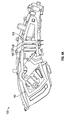
- FIGS. 1A-1B illustrate cross-sectional views of an antenna with a shorting conductor for a hearing assistance device, according to various embodiments of the present subject matter.
- current flow in antenna loops 110 is changed by selectively placing one or more conductors 105 in parallel with portions of one or more loop segments, creating a shorter path that some of the current follows.
- Loop 110 is one of two or more parallel antenna loops, in an embodiment.
- the current distribution on the antenna is changed to reduce coupling to hearing assistance electronics such as a telecoil 115.
- Significant improvement in audible performance is achieved using the present subject matter while maintaining comparable radio frequency (RF) effective radiated power.
- RF radio frequency
- an antenna has a real portion of impedance of 3.98 ohms.
- the same antenna when using a shorting conductor of the present subject matter, exhibits a real portion of impedance of 2.24 ohms and a 0.4 dB increase in radiation efficiency.
- the present subject matter reduces audio artifacts without reducing antenna gain or changing the hearing aid size in various embodiments.
- FIG. 2 illustrates a three-dimensional electromagnetic field simulation for an antenna, according to various embodiments of the present subject matter.
- current flow in a first antenna loop 210 is changed by selectively placing one or more conductors 205 in parallel with portions of one or more loop segments, creating a shorter path that some of the current follows.
- current flow in a second antenna loop 212 is changed by selectively placing one or more conductors 205 in parallel with portions of one or more loop segments
- FIG. 3 illustrates a three-dimensional electromagnetic field simulation for a hearing assistance device, according to various embodiments of the present subject matter.
- current flow in a first antenna loop 310 is changed by selectively placing one or more conductors 305 in parallel with portions of one or more loop segments, creating a shorter path that some of the current follows.
- current flow in a second antenna loop 312 is changed by selectively placing one or more conductors 305 in parallel with portions of one or more loop segments. By adding one or more of the conductors 305, the current distribution on the antenna is changed to reduce coupling to hearing assistance electronics 320.
- FIGS. 2-3 show that most of the current flows through the shorting bar, but there is some current that flows in the structure which has been shorted out. This explains why gain and radiation efficiency performance can remain similar to that of the unshorted loop. If the portions of the structure which have been shorted out were removed, the effective aperture, gain and efficiency would be significantly reduced.
- the results of these simulations show that improved antenna harmonic response can be realized with selective inclusion of shorting conductors to control where and how much current flows on the antenna conductor or conductors, in various embodiments
- FIGS. 4A-4B illustrate cross-sectional views of an antenna with multiple shorting conductors for a hearing assistance device 100, according to various embodiments of the present subject matter.
- current flow in antenna loops 110 is changed by selectively placing one or more conductors 105 in parallel with portions of one or more loop segments, creating a shorter path that some of the current follows.
- Loop 110 is one of two or more parallel antenna loops, in an embodiment.
- the current distribution on the antenna is changed to reduce coupling to hearing assistance electronics such as a telecoil 115.
- one or more shorting conductors can be placed in each of one or more loops.
- shorting conductor widths can be varied to vary the amount of current through the conductors.
- Shorting conductor sections could be curved, follow split or meandered paths, in various embodiments.
- antennas with multiple loops can have the same or different shorting conductor configurations applied to each individual loop.
- Shorting conductors can be used in band-style loops or hybrid combinations, in various embodiments.
- the present subject matter can be implemented in antennas with flex, wires, metal-on-plastics, conductive printing and other fabrication methods that can create current loops with shorting conductors, according to various embodiments.
- capacitively coupled fingers can be used in place of the shorting conductors.
- the present subject matter provides for smaller, better performing wireless hearing assistance devices.
- the wireless communications can include standard or nonstandard communications.
- standard wireless communications include link protocols including, but not limited to, BluetoothTM, IEEE 802.11(wireless LANs), 802.15 (WPANs), 802.16 (WiMAX), cellular protocols including, but not limited to CDMA and GSM, ZigBee, and ultra-wideband (UWB) technologies.
- Such protocols support radio frequency communications and some support infrared communications.
- the present system is demonstrated as a radio system, it is possible that other forms of wireless communications can be used such as ultrasonic, optical, infrared, and others.
- the standards which can be used include past and present standards. It is also contemplated that future versions of these standards and new future standards may be employed without departing from the scope of the present subject matter.
- the wireless communications support a connection from other devices.
- Such connections include, but are not limited to, one or more mono or stereo connections or digital connections having link protocols including, but not limited to 802.3 (Ethernet), 802.4, 802.5, USB, SPI, PCM, ATM, Fibre-channel, Firewire or 1394, InfiniBand, or a native streaming interface.
- link protocols including, but not limited to 802.3 (Ethernet), 802.4, 802.5, USB, SPI, PCM, ATM, Fibre-channel, Firewire or 1394, InfiniBand, or a native streaming interface.
- such connections include all past and present link protocols. It is also contemplated that future versions of these protocols and new future standards may be employed without departing from the scope of the present subject matter.
- Hearing assistance devices typically include an enclosure or housing, a microphone, hearing assistance device electronics including processing electronics, and a speaker or receiver. It is understood that in various embodiments the microphone is optional. It is understood that in various embodiments the receiver is optional. Antenna configurations may vary and may be included within an enclosure for the electronics or be external to an enclosure for the electronics. Thus, the examples set forth herein are intended to be demonstrative and not a limiting or exhaustive depiction of variations.
- any hearing assistance device may be used without departing from the scope and the devices depicted in the figures are intended to demonstrate the subject matter, but not in a limited, exhaustive, or exclusive sense. It is also understood that the present subject matter can be used with a device designed for use in the right ear or the left ear or both ears of the wearer.
- the hearing aids referenced in this patent application include a processor.
- the processor may be a digital signal processor (DSP), microprocessor, microcontroller, other digital logic, or combinations thereof.
- DSP digital signal processor
- the processing of signals referenced in this application can be performed using the processor. Processing may be done in the digital domain, the analog domain, or combinations thereof. Processing may be done using subband processing techniques. Processing may be done with frequency domain or time domain approaches. Some processing may involve both frequency and time domain aspects. For brevity, in some examples drawings may omit certain blocks that perform frequency synthesis, frequency analysis, analog-to-digital conversion, digital-to-analog conversion, amplification, audio decoding, and certain types of filtering and processing.
- the processor is adapted to perform instructions stored in memory which may or may not be explicitly shown.
- Various types of memory may be used, including volatile and nonvolatile forms of memory.
- instructions are performed by the processor to perform a number of signal processing tasks.
- analog components are in communication with the processor to perform signal tasks, such as microphone reception, or receiver sound embodiments (i.e., in applications where such transducers are used).
- signal tasks such as microphone reception, or receiver sound embodiments (i.e., in applications where such transducers are used).
- different realizations of the block diagrams, circuits, and processes set forth herein may occur without departing from the scope of the present subject matter.
- hearing assistance devices including hearing aids, including but not limited to, behind-the-ear (BTE), in-the-ear (ITE), in-the-canal (ITC), receiver-in-canal (RIC), or completely-in-the-canal (CIC) type hearing aids.
- BTE behind-the-ear
- ITE in-the-ear
- ITC in-the-canal
- RIC receiver-in-canal
- CIC completely-in-the-canal
- hearing assistance devices including but not limited to, behind-the-ear (BTE), in-the-ear (ITE), in-the-canal (ITC), receiver-in-canal (RIC), or completely-in-the-canal (CIC) type hearing aids.
- BTE behind-the-ear
- ITE in-the-ear
- ITC in-the-canal
- RIC receiver-in-canal
- CIC completely-in-the-canal
- hearing assistance devices including but not limited to, behind-the-ear (BTE), in
- the present subject matter can also be used in hearing assistance devices generally, such as cochlear implant type hearing devices and such as deep insertion devices having a transducer, such as a receiver or microphone, whether custom fitted, standard, open fitted or occlusive fitted. It is understood that other hearing assistance devices not expressly stated herein may be used in conjunction with the present subject matter.
Landscapes
- Engineering & Computer Science (AREA)
- Computer Networks & Wireless Communication (AREA)
- Health & Medical Sciences (AREA)
- General Health & Medical Sciences (AREA)
- Neurosurgery (AREA)
- Otolaryngology (AREA)
- Physics & Mathematics (AREA)
- Acoustics & Sound (AREA)
- Signal Processing (AREA)
- Details Of Aerials (AREA)
Abstract
Description
- The present application claims the benefit of priority under 35 U.S.C. §119(e) of
U.S. Provisional Patent Application Number 61/817,755, filed April 30, 2013 - This document relates generally to hearing assistance systems and more particularly to methods and apparatus for small loop antennas with shorting conductors for hearing assistance devices.
- Modern hearing assistance devices, such as hearing aids, are electronic instruments worn in or around the ear that compensate for hearing losses by specially amplifying sound. Some hearing aids include an antenna for radio frequency communications. Wearers of hearing aids can experience problems with antenna communication. Examples include, but are not limited to, unwanted coupling between the antenna and other hearing aid components which causes artifacts, noise and interference. To limit this unwanted coupling, previous methods have included shielding or moving components farther away from the antenna to reduce unwanted coupling and reducing the physical aperture of the antenna for harmonic response and impedance improvements. However, adding shielding increases the part-count, adds assembly complexity, can degrade wireless performance and may increase the size of the hearing aid. Likewise, moving components farther away from the antenna increases the minimum size of the hearing aid. In addition, reducing the antenna physical aperture size usually reduces radiation efficiency and degrades performance.
- Accordingly, there is a need in the art for improved systems and methods for improving antenna performance for hearing assistance devices.
- Disclosed herein, among other things, are methods and apparatus for mitigating antenna interference for hearing assistance devices. One aspect of the present subject matter includes a hearing assistance device, such as a hearing aid, for a wearer including hearing aid electronics and an antenna including a loop segment. According to various embodiments, one or more conductors are connected in parallel with a portion of the loop segment. The conductors electrically short the loop segment to change current distribution in the antenna. The conductors are configured to reduce unwanted coupling between the hearing aid electronics and the antenna, according to one embodiment. The conductors are configured to increase desired coupling, adjust antenna frequency response, adjust electromagnetic field distribution, reduce antenna harmonic response to improve radiated emissions, adjust antenna impedance and quality factor (Q) to optimize for a radio transceiver, and/or maintain desired antenna physical aperture, gain and efficiency, in various embodiments.
- This Summary is an overview of some of the teachings of the present application and not intended to be an exclusive or exhaustive treatment of the present subject matter. Further details about the present subject matter are found in the detailed description and appended claims. The scope of the present invention is defined by the appended claims and their legal equivalents.
-
-
FIGS. 1A-1B illustrate three-dimensional views of an antenna with a shorting conductor for a hearing assistance device, according to various embodiments of the present subject matter. -
FIG. 2 illustrates a three-dimensional electromagnetic field simulation for an antenna, according to various embodiments of the present subject matter. -
FIG. 3 illustrates a three-dimensional electromagnetic field simulation for a hearing assistance device, according to various embodiments of the present subject matter. -
FIGS. 4A-4B illustrate cross-sectional views of an antenna with multiple shorting conductors for a hearing assistance device, according to various embodiments of the present subject matter. - The following detailed description of the present subject matter refers to subject matter in the accompanying drawings which show, by way of illustration, specific aspects and embodiments in which the present subject matter may be practiced. These embodiments are described in sufficient detail to enable those skilled in the art to practice the present subject matter. References to "an", "one", or "various" embodiments in this disclosure are not necessarily to the same embodiment, and such references contemplate more than one embodiment. The following detailed description is demonstrative and not to be taken in a limiting sense. The scope of the present subject matter is defined by the appended claims, along with the full scope of legal equivalents to which such claims are entitled.
- The present detailed description will discuss hearing assistance devices using the example of hearing aids. Hearing aids are only one type of hearing assistance device. Other hearing assistance devices include, but are not limited to, those in this document. It is understood that their use in the description is intended to demonstrate the present subject matter, but not in a limited or exclusive or exhaustive sense.
- Disclosed herein, among other things, are methods and apparatus for mitigating antenna interference for hearing assistance devices. One aspect of the present subject matter includes a hearing assistance device, such as a hearing aid, for a wearer including hearing assistance electronics and an antenna including a loop segment. According to various embodiments, one or more conductors are connected in parallel with a portion of the loop segment. The conductors electrically short the loop segment to change current distribution in the antenna. The conductors are further configured to increase desired coupling, adjust antenna frequency response, adjust electric field distribution, adjust magnetic field distribution, reduce antenna harmonic response to improve radiated emissions, adjust antenna impedance and quality factor (Q) to optimize for a radio transceiver, and/or maintain desired antenna physical aperture, gain and efficiency, in various embodiments.
- In various embodiments, adding shorting conductor(s) changes the shape of the current path(s) and concentration of antenna currents, which can be used to make changes in antenna impedance, antenna frequency response, and in electric and magnetic field distributions. The problem of reducing unwanted coupling between the hearing aid electronics and the antenna is only one of the problems that can be solved by adding one or more shorting conductors of the present subject matter. Other problems can be solved by adding shorting bars or conductors of the desired shape in the desired location. In one example, the sorting conductors are configured to change the antenna frequency response. If a hearing aid antenna is not meeting radiated emissions regulatory requirements because it is radiating too much power at certain out-of-band frequencies, such as at harmonics of the fundamental operating frequency, the antenna gain or radiation efficiency can be reduced at the unwanted (out-of-band) frequency or frequencies relative to the fundamental (operating) frequency by adding one or more shorting conductors of the present subject matter. Thus, the unwanted emitted power level is reduced to meet the regulatory limits. In another example, the shorting conductors are configured to change the antenna impedance to achieve a desired impedance match with the RF circuit. In another example, the shorting conductors are configured to increase desired coupling rather than decrease unwanted coupling. In other examples, the shorting conductors are configured to achieve a desired combination of changes to antenna impedance, antenna frequency response, and electromagnetic field distributions, or other combinations, to solve more than one problem.
-
FIGS. 1A-1B illustrate cross-sectional views of an antenna with a shorting conductor for a hearing assistance device, according to various embodiments of the present subject matter. According to various embodiments, current flow inantenna loops 110 is changed by selectively placing one ormore conductors 105 in parallel with portions of one or more loop segments, creating a shorter path that some of the current follows.Loop 110 is one of two or more parallel antenna loops, in an embodiment. By adding aconductor 105, the current distribution on the antenna is changed to reduce coupling to hearing assistance electronics such as atelecoil 115. Significant improvement in audible performance is achieved using the present subject matter while maintaining comparable radio frequency (RF) effective radiated power. For example, at 900MHz, an antenna has a real portion of impedance of 3.98 ohms. The same antenna, when using a shorting conductor of the present subject matter, exhibits a real portion of impedance of 2.24 ohms and a 0.4 dB increase in radiation efficiency. In addition, the present subject matter reduces audio artifacts without reducing antenna gain or changing the hearing aid size in various embodiments. -
FIG. 2 illustrates a three-dimensional electromagnetic field simulation for an antenna, according to various embodiments of the present subject matter. According to various embodiments, current flow in afirst antenna loop 210 is changed by selectively placing one ormore conductors 205 in parallel with portions of one or more loop segments, creating a shorter path that some of the current follows. In addition, current flow in asecond antenna loop 212 is changed by selectively placing one ormore conductors 205 in parallel with portions of one or more loop segments -
FIG. 3 illustrates a three-dimensional electromagnetic field simulation for a hearing assistance device, according to various embodiments of the present subject matter. According to various embodiments, current flow in afirst antenna loop 310 is changed by selectively placing one ormore conductors 305 in parallel with portions of one or more loop segments, creating a shorter path that some of the current follows. In addition, current flow in asecond antenna loop 312 is changed by selectively placing one ormore conductors 305 in parallel with portions of one or more loop segments. By adding one or more of theconductors 305, the current distribution on the antenna is changed to reduce coupling to hearingassistance electronics 320. - The three-dimensional electromagnetic field simulations of
FIGS. 2-3 show that most of the current flows through the shorting bar, but there is some current that flows in the structure which has been shorted out. This explains why gain and radiation efficiency performance can remain similar to that of the unshorted loop. If the portions of the structure which have been shorted out were removed, the effective aperture, gain and efficiency would be significantly reduced. The results of these simulations show that improved antenna harmonic response can be realized with selective inclusion of shorting conductors to control where and how much current flows on the antenna conductor or conductors, in various embodiments -
FIGS. 4A-4B illustrate cross-sectional views of an antenna with multiple shorting conductors for ahearing assistance device 100, according to various embodiments of the present subject matter. According to various embodiments, current flow inantenna loops 110 is changed by selectively placing one ormore conductors 105 in parallel with portions of one or more loop segments, creating a shorter path that some of the current follows.Loop 110 is one of two or more parallel antenna loops, in an embodiment. By addingmultiple conductors 105, the current distribution on the antenna is changed to reduce coupling to hearing assistance electronics such as atelecoil 115. - Other embodiments are possible without departing from the scope of the present subject matter. For example, one or more shorting conductors can be placed in each of one or more loops. In various embodiments, shorting conductor widths can be varied to vary the amount of current through the conductors. Shorting conductor sections could be curved, follow split or meandered paths, in various embodiments. In various embodiments, antennas with multiple loops can have the same or different shorting conductor configurations applied to each individual loop. Shorting conductors can be used in band-style loops or hybrid combinations, in various embodiments. The present subject matter can be implemented in antennas with flex, wires, metal-on-plastics, conductive printing and other fabrication methods that can create current loops with shorting conductors, according to various embodiments. In one embodiment, capacitively coupled fingers can be used in place of the shorting conductors. The present subject matter provides for smaller, better performing wireless hearing assistance devices.
- Various embodiments of the present subject matter support wireless communications with a hearing assistance device. In various embodiments the wireless communications can include standard or nonstandard communications. Some examples of standard wireless communications include link protocols including, but not limited to, Bluetooth™, IEEE 802.11(wireless LANs), 802.15 (WPANs), 802.16 (WiMAX), cellular protocols including, but not limited to CDMA and GSM, ZigBee, and ultra-wideband (UWB) technologies. Such protocols support radio frequency communications and some support infrared communications. Although the present system is demonstrated as a radio system, it is possible that other forms of wireless communications can be used such as ultrasonic, optical, infrared, and others. It is understood that the standards which can be used include past and present standards. It is also contemplated that future versions of these standards and new future standards may be employed without departing from the scope of the present subject matter.
- The wireless communications support a connection from other devices. Such connections include, but are not limited to, one or more mono or stereo connections or digital connections having link protocols including, but not limited to 802.3 (Ethernet), 802.4, 802.5, USB, SPI, PCM, ATM, Fibre-channel, Firewire or 1394, InfiniBand, or a native streaming interface. In various embodiments, such connections include all past and present link protocols. It is also contemplated that future versions of these protocols and new future standards may be employed without departing from the scope of the present subject matter.
- It is understood that variations in communications protocols, antenna configurations, and combinations of components may be employed without departing from the scope of the present subject matter. Hearing assistance devices typically include an enclosure or housing, a microphone, hearing assistance device electronics including processing electronics, and a speaker or receiver. It is understood that in various embodiments the microphone is optional. It is understood that in various embodiments the receiver is optional. Antenna configurations may vary and may be included within an enclosure for the electronics or be external to an enclosure for the electronics. Thus, the examples set forth herein are intended to be demonstrative and not a limiting or exhaustive depiction of variations.
- It is further understood that any hearing assistance device may be used without departing from the scope and the devices depicted in the figures are intended to demonstrate the subject matter, but not in a limited, exhaustive, or exclusive sense. It is also understood that the present subject matter can be used with a device designed for use in the right ear or the left ear or both ears of the wearer.
- It is understood that the hearing aids referenced in this patent application include a processor. The processor may be a digital signal processor (DSP), microprocessor, microcontroller, other digital logic, or combinations thereof. The processing of signals referenced in this application can be performed using the processor. Processing may be done in the digital domain, the analog domain, or combinations thereof. Processing may be done using subband processing techniques. Processing may be done with frequency domain or time domain approaches. Some processing may involve both frequency and time domain aspects. For brevity, in some examples drawings may omit certain blocks that perform frequency synthesis, frequency analysis, analog-to-digital conversion, digital-to-analog conversion, amplification, audio decoding, and certain types of filtering and processing. In various embodiments the processor is adapted to perform instructions stored in memory which may or may not be explicitly shown. Various types of memory may be used, including volatile and nonvolatile forms of memory. In various embodiments, instructions are performed by the processor to perform a number of signal processing tasks. In such embodiments, analog components are in communication with the processor to perform signal tasks, such as microphone reception, or receiver sound embodiments (i.e., in applications where such transducers are used). In various embodiments, different realizations of the block diagrams, circuits, and processes set forth herein may occur without departing from the scope of the present subject matter.
- The present subject matter is demonstrated for hearing assistance devices, including hearing aids, including but not limited to, behind-the-ear (BTE), in-the-ear (ITE), in-the-canal (ITC), receiver-in-canal (RIC), or completely-in-the-canal (CIC) type hearing aids. It is understood that behind-the-ear type hearing aids may include devices that reside substantially behind the ear or over the ear. Such devices may include hearing aids with receivers associated with the electronics portion of the behind-the-ear device, or hearing aids of the type having receivers in the ear canal of the user, including but not limited to receiver-in-canal (RIC) or receiver-in-the-ear (RITE) designs. The present subject matter can also be used in hearing assistance devices generally, such as cochlear implant type hearing devices and such as deep insertion devices having a transducer, such as a receiver or microphone, whether custom fitted, standard, open fitted or occlusive fitted. It is understood that other hearing assistance devices not expressly stated herein may be used in conjunction with the present subject matter.
- This application is intended to cover adaptations or variations of the present subject matter. It is to be understood that the above description is intended to be illustrative, and not restrictive. The scope of the present subject matter should be determined with reference to the appended claims, along with the full scope of legal equivalents to which such claims are entitled.
Claims (15)
- A hearing aid for a wearer, comprising:hearing aid electronics;an antenna including a loop segment; andone or more conductors in parallel with a portion of the loop segment, at least one of the one or more conductors electrically shorting the loop segment to change current distribution in the antenna.
- The hearing aid of claim 1, wherein at least one of the one or more conductors is configured to reduce unwanted coupling between the hearing aid electronics and the antenna.
- The hearing aid of claim 1 or claim 2, wherein at least one of the one or more conductors is configured to increase desired coupling between the hearing aid electronics and the antenna.
- The hearing aid of any of the preceding claims, wherein at least one of the one or more conductors is configured to adjust antenna frequency response.
- The hearing aid of any of the preceding claims, wherein at least one of the one or more conductors is configured to adjust antenna impedance.
- The hearing aid of any of the preceding claims, wherein at least one of the one or more conductors is configured to adjust electric field distribution.
- The hearing aid of any of the preceding claims, wherein at least one of the one or more conductors is configured to adjust magnetic field distribution.
- The hearing aid of any of the preceding claims, wherein the antenna includes multiple loop segments and wherein one or more conductors are configured in parallel with one or more of the multiple loop segments.
- The hearing aid of any of the preceding claims, wherein a width of the one of the one or more conductors is varied to adjust current flowing through the antenna.
- The hearing aid of any of the preceding claims, wherein at least one of the one or more conductors is curved.
- The hearing aid of any of the preceding claims, wherein at least one of the one or more conductors follows a split path.
- A method for making an antenna for a hearing aid, the method comprising:connecting a conductor in parallel with a portion of a loop segment of the antenna, including electrically shorting the loop segment to change current distribution in the antenna.
- The method of claim 12, wherein connecting the conductor is performed during manufacture of the antenna.
- The method of claim 12, wherein connecting the conductor is performed during assembly of the hearing assistance device.
- The method of any of claim 12 through claim 14, wherein connecting the conductor includes using at least one of a wire, metal-on-plastics, or conductive printing.
Applications Claiming Priority (2)
| Application Number | Priority Date | Filing Date | Title |
|---|---|---|---|
| US201361817755P | 2013-04-30 | 2013-04-30 | |
| US14/074,027 US10743116B2 (en) | 2013-04-30 | 2013-11-07 | Small loop antenna with shorting conductors for hearing assistance devices |
Publications (2)
| Publication Number | Publication Date |
|---|---|
| EP2802037A1 true EP2802037A1 (en) | 2014-11-12 |
| EP2802037B1 EP2802037B1 (en) | 2023-12-27 |
Family
ID=50677970
Family Applications (1)
| Application Number | Title | Priority Date | Filing Date |
|---|---|---|---|
| EP14166610.7A Active EP2802037B1 (en) | 2013-04-30 | 2014-04-30 | Small loop antenna with shorting conductors for hearing assistance devices |
Country Status (2)
| Country | Link |
|---|---|
| US (1) | US10743116B2 (en) |
| EP (1) | EP2802037B1 (en) |
Cited By (3)
| Publication number | Priority date | Publication date | Assignee | Title |
|---|---|---|---|---|
| EP3110171A1 (en) * | 2015-05-07 | 2016-12-28 | Stephen Paul Flood | Hearing aid bowtie antenna optimized for ear to ear communications |
| US10297910B2 (en) | 2016-10-21 | 2019-05-21 | Starkey Laboratories, Inc. | Hearing device with bowtie antenna optimized for specific band |
| DE102020201480A1 (en) | 2020-02-06 | 2021-08-12 | Sivantos Pte. Ltd. | Hearing aid |
Families Citing this family (23)
| Publication number | Priority date | Publication date | Assignee | Title |
|---|---|---|---|---|
| US8934984B2 (en) | 2007-05-31 | 2015-01-13 | Cochlear Limited | Behind-the-ear (BTE) prosthetic device with antenna |
| DK2725655T3 (en) | 2010-10-12 | 2021-09-20 | Gn Hearing As | Antenna system for a hearing aid |
| DK2458675T3 (en) | 2010-10-12 | 2018-01-22 | Gn Hearing As | Hearing aid with antenna |
| DK201270410A (en) * | 2012-07-06 | 2014-01-07 | Gn Resound As | BTE hearing aid with an antenna partition plane |
| DK201270411A (en) | 2012-07-06 | 2014-01-07 | Gn Resound As | BTE hearing aid having two driven antennas |
| US9554219B2 (en) | 2012-07-06 | 2017-01-24 | Gn Resound A/S | BTE hearing aid having a balanced antenna |
| US9237404B2 (en) | 2012-12-28 | 2016-01-12 | Gn Resound A/S | Dipole antenna for a hearing aid |
| US9237405B2 (en) | 2013-11-11 | 2016-01-12 | Gn Resound A/S | Hearing aid with an antenna |
| US9686621B2 (en) | 2013-11-11 | 2017-06-20 | Gn Hearing A/S | Hearing aid with an antenna |
| US9408003B2 (en) | 2013-11-11 | 2016-08-02 | Gn Resound A/S | Hearing aid with an antenna |
| US9883295B2 (en) | 2013-11-11 | 2018-01-30 | Gn Hearing A/S | Hearing aid with an antenna |
| US9743198B2 (en) | 2014-01-15 | 2017-08-22 | Starkey Laboratories, Inc. | Systems and methods for hearing assistance device antenna |
| US10595138B2 (en) | 2014-08-15 | 2020-03-17 | Gn Hearing A/S | Hearing aid with an antenna |
| DK3029959T3 (en) | 2014-12-05 | 2021-10-04 | Oticon As | ANTENNA UNIT |
| US20170064651A1 (en) | 2015-08-28 | 2017-03-02 | Alex Volkov | Synchronization of audio streams and sampling rate for wireless communication |
| US10349192B2 (en) | 2015-08-28 | 2019-07-09 | Starkey Laboratories, Inc. | Antenna with flared cross-feed in a hearing assistance device |
| DK3664473T3 (en) * | 2015-12-14 | 2021-08-16 | Gn Hearing As | Hearing aid |
| US10051388B2 (en) * | 2016-09-21 | 2018-08-14 | Starkey Laboratories, Inc. | Radio frequency antenna for an in-the-ear hearing device |
| US10764695B2 (en) * | 2016-12-20 | 2020-09-01 | Sonova Ag | BTE hearing instrument comprising an open-end transmission line antenna |
| EP3499913B1 (en) | 2017-12-14 | 2020-12-02 | GN Hearing A/S | Multiple arm dipole antenna for hearing instrument |
| DE102018207179B4 (en) * | 2018-05-08 | 2020-03-19 | Sivantos Pte. Ltd. | Hearing aid with electronic frame and integrated antenna |
| US10841716B2 (en) * | 2019-03-29 | 2020-11-17 | Sonova Ag | Hearing device with two-half loop antenna |
| US11627420B2 (en) * | 2021-05-14 | 2023-04-11 | Bose Corporation | Loop antenna for hearing aid |
Citations (4)
| Publication number | Priority date | Publication date | Assignee | Title |
|---|---|---|---|---|
| US20030071757A1 (en) * | 2001-10-12 | 2003-04-17 | Murata Manufacturing Co., Ltd. | Loop antenna, surface-mounted antenna and communication equipment having the same |
| EP1555717A1 (en) * | 2004-01-13 | 2005-07-20 | Kabushiki Kaisha Toshiba | Mobile communication terminal with loop antenna |
| EP2200120A2 (en) * | 2008-12-19 | 2010-06-23 | Starkey Laboratories, Inc. | Parallel antennas for standard fit hearing assistance devices |
| WO2011000416A1 (en) * | 2009-06-30 | 2011-01-06 | Nokia Corporation | Apparatus for wireless communication comprising a loop like antenna |
Family Cites Families (12)
| Publication number | Priority date | Publication date | Assignee | Title |
|---|---|---|---|---|
| US3560983A (en) * | 1967-09-12 | 1971-02-02 | Volkers Research Corp | Omnidirectional loop antenna |
| US20050099341A1 (en) * | 2003-11-12 | 2005-05-12 | Gennum Corporation | Antenna for a wireless hearing aid system |
| ATE508590T1 (en) | 2004-02-19 | 2011-05-15 | Oticon As | HEARING AID WITH ANTENNA FOR RECEIVING AND TRANSMITTING ELECTROMAGNETIC SIGNALS AND SHIELDING BATTERY |
| US7593538B2 (en) | 2005-03-28 | 2009-09-22 | Starkey Laboratories, Inc. | Antennas for hearing aids |
| DE602006009060D1 (en) | 2006-01-13 | 2009-10-22 | Research In Motion Ltd | Mobile communication device with electrically conductive straightening element and corresponding method |
| US7423605B2 (en) | 2006-01-13 | 2008-09-09 | Research In Motion Limited | Mobile wireless communications device including an electrically conductive director element and related methods |
| EP1821571A1 (en) | 2006-02-15 | 2007-08-22 | Oticon A/S | Loop antenna for in the ear audio device |
| JP4890386B2 (en) * | 2007-08-20 | 2012-03-07 | アルプス電気株式会社 | Antenna coil |
| JP4788791B2 (en) * | 2009-02-27 | 2011-10-05 | Tdk株式会社 | Antenna device |
| US9048539B2 (en) * | 2010-06-24 | 2015-06-02 | Netgear, Inc. | Mitigation of undesired electromagnetic radiation using passive elements |
| DK2725655T3 (en) * | 2010-10-12 | 2021-09-20 | Gn Hearing As | Antenna system for a hearing aid |
| US9319807B2 (en) * | 2012-02-28 | 2016-04-19 | Cochlear Limited | Device with combined antenna and transducer |
-
2013
- 2013-11-07 US US14/074,027 patent/US10743116B2/en active Active
-
2014
- 2014-04-30 EP EP14166610.7A patent/EP2802037B1/en active Active
Patent Citations (4)
| Publication number | Priority date | Publication date | Assignee | Title |
|---|---|---|---|---|
| US20030071757A1 (en) * | 2001-10-12 | 2003-04-17 | Murata Manufacturing Co., Ltd. | Loop antenna, surface-mounted antenna and communication equipment having the same |
| EP1555717A1 (en) * | 2004-01-13 | 2005-07-20 | Kabushiki Kaisha Toshiba | Mobile communication terminal with loop antenna |
| EP2200120A2 (en) * | 2008-12-19 | 2010-06-23 | Starkey Laboratories, Inc. | Parallel antennas for standard fit hearing assistance devices |
| WO2011000416A1 (en) * | 2009-06-30 | 2011-01-06 | Nokia Corporation | Apparatus for wireless communication comprising a loop like antenna |
Cited By (7)
| Publication number | Priority date | Publication date | Assignee | Title |
|---|---|---|---|---|
| EP3110171A1 (en) * | 2015-05-07 | 2016-12-28 | Stephen Paul Flood | Hearing aid bowtie antenna optimized for ear to ear communications |
| US10785583B2 (en) | 2015-05-07 | 2020-09-22 | Starkey Laboratories, Inc. | Hearing aid bowtie antenna optimized for ear to ear communications |
| US11432082B2 (en) | 2015-05-07 | 2022-08-30 | Starkey Laboratories, Inc. | Hearing aid bowtie antenna optimized for ear to ear communications |
| US11765527B2 (en) | 2015-05-07 | 2023-09-19 | Starkey Laboratories, Inc. | Hearing aid bowtie antenna optimized for ear to ear communications |
| US10297910B2 (en) | 2016-10-21 | 2019-05-21 | Starkey Laboratories, Inc. | Hearing device with bowtie antenna optimized for specific band |
| DE102020201480A1 (en) | 2020-02-06 | 2021-08-12 | Sivantos Pte. Ltd. | Hearing aid |
| US11496846B2 (en) | 2020-02-06 | 2022-11-08 | Sivantos Pte. Ltd. | Hearing aid |
Also Published As
| Publication number | Publication date |
|---|---|
| US10743116B2 (en) | 2020-08-11 |
| US20140321685A1 (en) | 2014-10-30 |
| EP2802037B1 (en) | 2023-12-27 |
Similar Documents
| Publication | Publication Date | Title |
|---|---|---|
| US10743116B2 (en) | Small loop antenna with shorting conductors for hearing assistance devices | |
| US20240430628A1 (en) | Radio frequency antenna for an in-the-ear hearing device | |
| US10231066B2 (en) | Hearing assistance device with balanced feed-line for antenna | |
| EP3313096B1 (en) | Hearing device with bowtie antenna optimized for specific band | |
| EP3110171B1 (en) | Hearing aid bowtie antenna optimized for ear to ear communications | |
| US20140328507A1 (en) | Increasing antenna performance for wireless hearing assistance devices | |
| EP2827613A1 (en) | System and method for embedding conductive traces into hearing assistance device housings | |
| US10951998B2 (en) | Antenna with flared cross-feed in a hearing assistance device | |
| EP3188509A1 (en) | Hearing assistance device earhook and sound tube antennas | |
| US10511920B2 (en) | Ear-worn electronic device incorporating directional magnetic antenna | |
| EP3726854A2 (en) | Hearing device with two-half loop antenna | |
| US12580300B2 (en) | Circular polarized spiral antenna for hearing assistance devices | |
| EP2992688B1 (en) | Increasing antenna performance for wireless hearing assistance devices | |
| DK2942979T3 (en) | IMPROVING ANTENNA PERFORMANCE FOR WIRELESS HEARINGS | |
| EP3029958B1 (en) | Filter to suppress harmonics for an antenna | |
| EP3598776A1 (en) | Multi-frequency separation |
Legal Events
| Date | Code | Title | Description |
|---|---|---|---|
| PUAI | Public reference made under article 153(3) epc to a published international application that has entered the european phase |
Free format text: ORIGINAL CODE: 0009012 |
|
| 17P | Request for examination filed |
Effective date: 20140430 |
|
| AK | Designated contracting states |
Kind code of ref document: A1 Designated state(s): AL AT BE BG CH CY CZ DE DK EE ES FI FR GB GR HR HU IE IS IT LI LT LU LV MC MK MT NL NO PL PT RO RS SE SI SK SM TR |
|
| AX | Request for extension of the european patent |
Extension state: BA ME |
|
| STAA | Information on the status of an ep patent application or granted ep patent |
Free format text: STATUS: EXAMINATION IS IN PROGRESS |
|
| 17Q | First examination report despatched |
Effective date: 20190904 |
|
| REG | Reference to a national code |
Ref country code: DE Free format text: PREVIOUS MAIN CLASS: H01Q0001270000 Ipc: H01Q0005364000 Ref country code: DE Ref legal event code: R079 Ref document number: 602014089186 Country of ref document: DE Free format text: PREVIOUS MAIN CLASS: H01Q0001270000 Ipc: H01Q0005364000 |
|
| GRAP | Despatch of communication of intention to grant a patent |
Free format text: ORIGINAL CODE: EPIDOSNIGR1 |
|
| STAA | Information on the status of an ep patent application or granted ep patent |
Free format text: STATUS: GRANT OF PATENT IS INTENDED |
|
| RIC1 | Information provided on ipc code assigned before grant |
Ipc: H04R 25/00 20060101ALI20230718BHEP Ipc: H01Q 1/44 20060101ALI20230718BHEP Ipc: H01Q 7/00 20060101ALI20230718BHEP Ipc: H01Q 1/27 20060101ALI20230718BHEP Ipc: H01Q 5/364 20150101AFI20230718BHEP |
|
| INTG | Intention to grant announced |
Effective date: 20230818 |
|
| GRAS | Grant fee paid |
Free format text: ORIGINAL CODE: EPIDOSNIGR3 |
|
| GRAA | (expected) grant |
Free format text: ORIGINAL CODE: 0009210 |
|
| STAA | Information on the status of an ep patent application or granted ep patent |
Free format text: STATUS: THE PATENT HAS BEEN GRANTED |
|
| AK | Designated contracting states |
Kind code of ref document: B1 Designated state(s): AL AT BE BG CH CY CZ DE DK EE ES FI FR GB GR HR HU IE IS IT LI LT LU LV MC MK MT NL NO PL PT RO RS SE SI SK SM TR |
|
| REG | Reference to a national code |
Ref country code: GB Ref legal event code: FG4D |
|
| REG | Reference to a national code |
Ref country code: CH Ref legal event code: EP |
|
| REG | Reference to a national code |
Ref country code: DE Ref legal event code: R096 Ref document number: 602014089186 Country of ref document: DE |
|
| P01 | Opt-out of the competence of the unified patent court (upc) registered |
Effective date: 20231130 |
|
| REG | Reference to a national code |
Ref country code: IE Ref legal event code: FG4D |
|
| PG25 | Lapsed in a contracting state [announced via postgrant information from national office to epo] |
Ref country code: GR Free format text: LAPSE BECAUSE OF FAILURE TO SUBMIT A TRANSLATION OF THE DESCRIPTION OR TO PAY THE FEE WITHIN THE PRESCRIBED TIME-LIMIT Effective date: 20240328 |
|
| REG | Reference to a national code |
Ref country code: LT Ref legal event code: MG9D |
|
| PG25 | Lapsed in a contracting state [announced via postgrant information from national office to epo] |
Ref country code: LT Free format text: LAPSE BECAUSE OF FAILURE TO SUBMIT A TRANSLATION OF THE DESCRIPTION OR TO PAY THE FEE WITHIN THE PRESCRIBED TIME-LIMIT Effective date: 20231227 |
|
| PG25 | Lapsed in a contracting state [announced via postgrant information from national office to epo] |
Ref country code: ES Free format text: LAPSE BECAUSE OF FAILURE TO SUBMIT A TRANSLATION OF THE DESCRIPTION OR TO PAY THE FEE WITHIN THE PRESCRIBED TIME-LIMIT Effective date: 20231227 |
|
| PG25 | Lapsed in a contracting state [announced via postgrant information from national office to epo] |
Ref country code: LT Free format text: LAPSE BECAUSE OF FAILURE TO SUBMIT A TRANSLATION OF THE DESCRIPTION OR TO PAY THE FEE WITHIN THE PRESCRIBED TIME-LIMIT Effective date: 20231227 Ref country code: GR Free format text: LAPSE BECAUSE OF FAILURE TO SUBMIT A TRANSLATION OF THE DESCRIPTION OR TO PAY THE FEE WITHIN THE PRESCRIBED TIME-LIMIT Effective date: 20240328 Ref country code: FI Free format text: LAPSE BECAUSE OF FAILURE TO SUBMIT A TRANSLATION OF THE DESCRIPTION OR TO PAY THE FEE WITHIN THE PRESCRIBED TIME-LIMIT Effective date: 20231227 Ref country code: ES Free format text: LAPSE BECAUSE OF FAILURE TO SUBMIT A TRANSLATION OF THE DESCRIPTION OR TO PAY THE FEE WITHIN THE PRESCRIBED TIME-LIMIT Effective date: 20231227 Ref country code: BG Free format text: LAPSE BECAUSE OF FAILURE TO SUBMIT A TRANSLATION OF THE DESCRIPTION OR TO PAY THE FEE WITHIN THE PRESCRIBED TIME-LIMIT Effective date: 20240327 |
|
| REG | Reference to a national code |
Ref country code: NL Ref legal event code: MP Effective date: 20231227 |
|
| REG | Reference to a national code |
Ref country code: AT Ref legal event code: MK05 Ref document number: 1645411 Country of ref document: AT Kind code of ref document: T Effective date: 20231227 |
|
| PG25 | Lapsed in a contracting state [announced via postgrant information from national office to epo] |
Ref country code: NL Free format text: LAPSE BECAUSE OF FAILURE TO SUBMIT A TRANSLATION OF THE DESCRIPTION OR TO PAY THE FEE WITHIN THE PRESCRIBED TIME-LIMIT Effective date: 20231227 |
|
| PG25 | Lapsed in a contracting state [announced via postgrant information from national office to epo] |
Ref country code: SE Free format text: LAPSE BECAUSE OF FAILURE TO SUBMIT A TRANSLATION OF THE DESCRIPTION OR TO PAY THE FEE WITHIN THE PRESCRIBED TIME-LIMIT Effective date: 20231227 Ref country code: RS Free format text: LAPSE BECAUSE OF FAILURE TO SUBMIT A TRANSLATION OF THE DESCRIPTION OR TO PAY THE FEE WITHIN THE PRESCRIBED TIME-LIMIT Effective date: 20231227 Ref country code: NO Free format text: LAPSE BECAUSE OF FAILURE TO SUBMIT A TRANSLATION OF THE DESCRIPTION OR TO PAY THE FEE WITHIN THE PRESCRIBED TIME-LIMIT Effective date: 20240327 Ref country code: NL Free format text: LAPSE BECAUSE OF FAILURE TO SUBMIT A TRANSLATION OF THE DESCRIPTION OR TO PAY THE FEE WITHIN THE PRESCRIBED TIME-LIMIT Effective date: 20231227 Ref country code: LV Free format text: LAPSE BECAUSE OF FAILURE TO SUBMIT A TRANSLATION OF THE DESCRIPTION OR TO PAY THE FEE WITHIN THE PRESCRIBED TIME-LIMIT Effective date: 20231227 Ref country code: HR Free format text: LAPSE BECAUSE OF FAILURE TO SUBMIT A TRANSLATION OF THE DESCRIPTION OR TO PAY THE FEE WITHIN THE PRESCRIBED TIME-LIMIT Effective date: 20231227 |
|
| PG25 | Lapsed in a contracting state [announced via postgrant information from national office to epo] |
Ref country code: IS Free format text: LAPSE BECAUSE OF FAILURE TO SUBMIT A TRANSLATION OF THE DESCRIPTION OR TO PAY THE FEE WITHIN THE PRESCRIBED TIME-LIMIT Effective date: 20240427 |
|
| PG25 | Lapsed in a contracting state [announced via postgrant information from national office to epo] |
Ref country code: CZ Free format text: LAPSE BECAUSE OF FAILURE TO SUBMIT A TRANSLATION OF THE DESCRIPTION OR TO PAY THE FEE WITHIN THE PRESCRIBED TIME-LIMIT Effective date: 20231227 Ref country code: AT Free format text: LAPSE BECAUSE OF FAILURE TO SUBMIT A TRANSLATION OF THE DESCRIPTION OR TO PAY THE FEE WITHIN THE PRESCRIBED TIME-LIMIT Effective date: 20231227 |
|
| PG25 | Lapsed in a contracting state [announced via postgrant information from national office to epo] |
Ref country code: SK Free format text: LAPSE BECAUSE OF FAILURE TO SUBMIT A TRANSLATION OF THE DESCRIPTION OR TO PAY THE FEE WITHIN THE PRESCRIBED TIME-LIMIT Effective date: 20231227 |
|
| PG25 | Lapsed in a contracting state [announced via postgrant information from national office to epo] |
Ref country code: SM Free format text: LAPSE BECAUSE OF FAILURE TO SUBMIT A TRANSLATION OF THE DESCRIPTION OR TO PAY THE FEE WITHIN THE PRESCRIBED TIME-LIMIT Effective date: 20231227 Ref country code: SK Free format text: LAPSE BECAUSE OF FAILURE TO SUBMIT A TRANSLATION OF THE DESCRIPTION OR TO PAY THE FEE WITHIN THE PRESCRIBED TIME-LIMIT Effective date: 20231227 Ref country code: RO Free format text: LAPSE BECAUSE OF FAILURE TO SUBMIT A TRANSLATION OF THE DESCRIPTION OR TO PAY THE FEE WITHIN THE PRESCRIBED TIME-LIMIT Effective date: 20231227 Ref country code: IT Free format text: LAPSE BECAUSE OF FAILURE TO SUBMIT A TRANSLATION OF THE DESCRIPTION OR TO PAY THE FEE WITHIN THE PRESCRIBED TIME-LIMIT Effective date: 20231227 Ref country code: IS Free format text: LAPSE BECAUSE OF FAILURE TO SUBMIT A TRANSLATION OF THE DESCRIPTION OR TO PAY THE FEE WITHIN THE PRESCRIBED TIME-LIMIT Effective date: 20240427 Ref country code: EE Free format text: LAPSE BECAUSE OF FAILURE TO SUBMIT A TRANSLATION OF THE DESCRIPTION OR TO PAY THE FEE WITHIN THE PRESCRIBED TIME-LIMIT Effective date: 20231227 Ref country code: CZ Free format text: LAPSE BECAUSE OF FAILURE TO SUBMIT A TRANSLATION OF THE DESCRIPTION OR TO PAY THE FEE WITHIN THE PRESCRIBED TIME-LIMIT Effective date: 20231227 Ref country code: AT Free format text: LAPSE BECAUSE OF FAILURE TO SUBMIT A TRANSLATION OF THE DESCRIPTION OR TO PAY THE FEE WITHIN THE PRESCRIBED TIME-LIMIT Effective date: 20231227 |
|
| PG25 | Lapsed in a contracting state [announced via postgrant information from national office to epo] |
Ref country code: PL Free format text: LAPSE BECAUSE OF FAILURE TO SUBMIT A TRANSLATION OF THE DESCRIPTION OR TO PAY THE FEE WITHIN THE PRESCRIBED TIME-LIMIT Effective date: 20231227 Ref country code: PT Free format text: LAPSE BECAUSE OF FAILURE TO SUBMIT A TRANSLATION OF THE DESCRIPTION OR TO PAY THE FEE WITHIN THE PRESCRIBED TIME-LIMIT Effective date: 20240429 |
|
| PG25 | Lapsed in a contracting state [announced via postgrant information from national office to epo] |
Ref country code: PT Free format text: LAPSE BECAUSE OF FAILURE TO SUBMIT A TRANSLATION OF THE DESCRIPTION OR TO PAY THE FEE WITHIN THE PRESCRIBED TIME-LIMIT Effective date: 20240429 Ref country code: PL Free format text: LAPSE BECAUSE OF FAILURE TO SUBMIT A TRANSLATION OF THE DESCRIPTION OR TO PAY THE FEE WITHIN THE PRESCRIBED TIME-LIMIT Effective date: 20231227 |
|
| REG | Reference to a national code |
Ref country code: DE Ref legal event code: R097 Ref document number: 602014089186 Country of ref document: DE |
|
| PG25 | Lapsed in a contracting state [announced via postgrant information from national office to epo] |
Ref country code: DK Free format text: LAPSE BECAUSE OF FAILURE TO SUBMIT A TRANSLATION OF THE DESCRIPTION OR TO PAY THE FEE WITHIN THE PRESCRIBED TIME-LIMIT Effective date: 20231227 |
|
| PG25 | Lapsed in a contracting state [announced via postgrant information from national office to epo] |
Ref country code: DK Free format text: LAPSE BECAUSE OF FAILURE TO SUBMIT A TRANSLATION OF THE DESCRIPTION OR TO PAY THE FEE WITHIN THE PRESCRIBED TIME-LIMIT Effective date: 20231227 |
|
| PLBE | No opposition filed within time limit |
Free format text: ORIGINAL CODE: 0009261 |
|
| STAA | Information on the status of an ep patent application or granted ep patent |
Free format text: STATUS: NO OPPOSITION FILED WITHIN TIME LIMIT |
|
| PG25 | Lapsed in a contracting state [announced via postgrant information from national office to epo] |
Ref country code: MC Free format text: LAPSE BECAUSE OF FAILURE TO SUBMIT A TRANSLATION OF THE DESCRIPTION OR TO PAY THE FEE WITHIN THE PRESCRIBED TIME-LIMIT Effective date: 20231227 |
|
| PG25 | Lapsed in a contracting state [announced via postgrant information from national office to epo] |
Ref country code: MC Free format text: LAPSE BECAUSE OF FAILURE TO SUBMIT A TRANSLATION OF THE DESCRIPTION OR TO PAY THE FEE WITHIN THE PRESCRIBED TIME-LIMIT Effective date: 20231227 |
|
| REG | Reference to a national code |
Ref country code: CH Ref legal event code: PL |
|
| 26N | No opposition filed |
Effective date: 20240930 |
|
| PG25 | Lapsed in a contracting state [announced via postgrant information from national office to epo] |
Ref country code: LU Free format text: LAPSE BECAUSE OF NON-PAYMENT OF DUE FEES Effective date: 20240430 |
|
| GBPC | Gb: european patent ceased through non-payment of renewal fee |
Effective date: 20240430 |
|
| REG | Reference to a national code |
Ref country code: BE Ref legal event code: MM Effective date: 20240430 |
|
| PG25 | Lapsed in a contracting state [announced via postgrant information from national office to epo] |
Ref country code: LU Free format text: LAPSE BECAUSE OF NON-PAYMENT OF DUE FEES Effective date: 20240430 |
|
| PG25 | Lapsed in a contracting state [announced via postgrant information from national office to epo] |
Ref country code: BE Free format text: LAPSE BECAUSE OF NON-PAYMENT OF DUE FEES Effective date: 20240430 |
|
| PG25 | Lapsed in a contracting state [announced via postgrant information from national office to epo] |
Ref country code: GB Free format text: LAPSE BECAUSE OF NON-PAYMENT OF DUE FEES Effective date: 20240430 |
|
| PG25 | Lapsed in a contracting state [announced via postgrant information from national office to epo] |
Ref country code: GB Free format text: LAPSE BECAUSE OF NON-PAYMENT OF DUE FEES Effective date: 20240430 Ref country code: BE Free format text: LAPSE BECAUSE OF NON-PAYMENT OF DUE FEES Effective date: 20240430 Ref country code: CH Free format text: LAPSE BECAUSE OF NON-PAYMENT OF DUE FEES Effective date: 20240430 |
|
| PG25 | Lapsed in a contracting state [announced via postgrant information from national office to epo] |
Ref country code: IE Free format text: LAPSE BECAUSE OF NON-PAYMENT OF DUE FEES Effective date: 20240430 |
|
| PG25 | Lapsed in a contracting state [announced via postgrant information from national office to epo] |
Ref country code: SI Free format text: LAPSE BECAUSE OF FAILURE TO SUBMIT A TRANSLATION OF THE DESCRIPTION OR TO PAY THE FEE WITHIN THE PRESCRIBED TIME-LIMIT Effective date: 20231227 |
|
| PGFP | Annual fee paid to national office [announced via postgrant information from national office to epo] |
Ref country code: DE Payment date: 20250313 Year of fee payment: 12 |
|
| PG25 | Lapsed in a contracting state [announced via postgrant information from national office to epo] |
Ref country code: CY Free format text: LAPSE BECAUSE OF FAILURE TO SUBMIT A TRANSLATION OF THE DESCRIPTION OR TO PAY THE FEE WITHIN THE PRESCRIBED TIME-LIMIT; INVALID AB INITIO Effective date: 20140430 |
|
| PG25 | Lapsed in a contracting state [announced via postgrant information from national office to epo] |
Ref country code: HU Free format text: LAPSE BECAUSE OF FAILURE TO SUBMIT A TRANSLATION OF THE DESCRIPTION OR TO PAY THE FEE WITHIN THE PRESCRIBED TIME-LIMIT; INVALID AB INITIO Effective date: 20140430 |
|
| PGFP | Annual fee paid to national office [announced via postgrant information from national office to epo] |
Ref country code: FR Payment date: 20260311 Year of fee payment: 13 |