EP2801978A1 - Jet pump, and bolt affixing device for jet pump beam - Google Patents
Jet pump, and bolt affixing device for jet pump beam Download PDFInfo
- Publication number
- EP2801978A1 EP2801978A1 EP20120860452 EP12860452A EP2801978A1 EP 2801978 A1 EP2801978 A1 EP 2801978A1 EP 20120860452 EP20120860452 EP 20120860452 EP 12860452 A EP12860452 A EP 12860452A EP 2801978 A1 EP2801978 A1 EP 2801978A1
- Authority
- EP
- European Patent Office
- Prior art keywords
- jet pump
- lock cap
- body housing
- pump beam
- bolt
- Prior art date
- Legal status (The legal status is an assumption and is not a legal conclusion. Google has not performed a legal analysis and makes no representation as to the accuracy of the status listed.)
- Granted
Links
Images






Classifications
-
- F—MECHANICAL ENGINEERING; LIGHTING; HEATING; WEAPONS; BLASTING
- F16—ENGINEERING ELEMENTS AND UNITS; GENERAL MEASURES FOR PRODUCING AND MAINTAINING EFFECTIVE FUNCTIONING OF MACHINES OR INSTALLATIONS; THERMAL INSULATION IN GENERAL
- F16B—DEVICES FOR FASTENING OR SECURING CONSTRUCTIONAL ELEMENTS OR MACHINE PARTS TOGETHER, e.g. NAILS, BOLTS, CIRCLIPS, CLAMPS, CLIPS OR WEDGES; JOINTS OR JOINTING
- F16B39/00—Locking of screws, bolts or nuts
- F16B39/02—Locking of screws, bolts or nuts in which the locking takes place after screwing down
- F16B39/10—Locking of screws, bolts or nuts in which the locking takes place after screwing down by a plate, spring, wire or ring immovable with regard to the bolt or object and mainly perpendicular to the axis of the bolt
-
- F—MECHANICAL ENGINEERING; LIGHTING; HEATING; WEAPONS; BLASTING
- F04—POSITIVE - DISPLACEMENT MACHINES FOR LIQUIDS; PUMPS FOR LIQUIDS OR ELASTIC FLUIDS
- F04F—PUMPING OF FLUID BY DIRECT CONTACT OF ANOTHER FLUID OR BY USING INERTIA OF FLUID TO BE PUMPED; SIPHONS
- F04F5/00—Jet pumps, i.e. devices in which flow is induced by pressure drop caused by velocity of another fluid flow
- F04F5/44—Component parts, details, or accessories not provided for in, or of interest apart from, groups F04F5/02 - F04F5/42
-
- F—MECHANICAL ENGINEERING; LIGHTING; HEATING; WEAPONS; BLASTING
- F16—ENGINEERING ELEMENTS AND UNITS; GENERAL MEASURES FOR PRODUCING AND MAINTAINING EFFECTIVE FUNCTIONING OF MACHINES OR INSTALLATIONS; THERMAL INSULATION IN GENERAL
- F16B—DEVICES FOR FASTENING OR SECURING CONSTRUCTIONAL ELEMENTS OR MACHINE PARTS TOGETHER, e.g. NAILS, BOLTS, CIRCLIPS, CLAMPS, CLIPS OR WEDGES; JOINTS OR JOINTING
- F16B37/00—Nuts or like thread-engaging members
- F16B37/14—Cap nuts; Nut caps or bolt caps
-
- G—PHYSICS
- G21—NUCLEAR PHYSICS; NUCLEAR ENGINEERING
- G21C—NUCLEAR REACTORS
- G21C15/00—Cooling arrangements within the pressure vessel containing the core; Selection of specific coolants
- G21C15/24—Promoting flow of the coolant
- G21C15/243—Promoting flow of the coolant for liquids
- G21C15/25—Promoting flow of the coolant for liquids using jet pumps
-
- G—PHYSICS
- G21—NUCLEAR PHYSICS; NUCLEAR ENGINEERING
- G21C—NUCLEAR REACTORS
- G21C19/00—Arrangements for treating, for handling, or for facilitating the handling of, fuel or other materials which are used within the reactor, e.g. within its pressure vessel
- G21C19/02—Details of handling arrangements
-
- G—PHYSICS
- G21—NUCLEAR PHYSICS; NUCLEAR ENGINEERING
- G21C—NUCLEAR REACTORS
- G21C19/00—Arrangements for treating, for handling, or for facilitating the handling of, fuel or other materials which are used within the reactor, e.g. within its pressure vessel
- G21C19/20—Arrangements for introducing objects into the pressure vessel; Arrangements for handling objects within the pressure vessel; Arrangements for removing objects from the pressure vessel
-
- F—MECHANICAL ENGINEERING; LIGHTING; HEATING; WEAPONS; BLASTING
- F16—ENGINEERING ELEMENTS AND UNITS; GENERAL MEASURES FOR PRODUCING AND MAINTAINING EFFECTIVE FUNCTIONING OF MACHINES OR INSTALLATIONS; THERMAL INSULATION IN GENERAL
- F16B—DEVICES FOR FASTENING OR SECURING CONSTRUCTIONAL ELEMENTS OR MACHINE PARTS TOGETHER, e.g. NAILS, BOLTS, CIRCLIPS, CLAMPS, CLIPS OR WEDGES; JOINTS OR JOINTING
- F16B39/00—Locking of screws, bolts or nuts
- F16B39/22—Locking of screws, bolts or nuts in which the locking takes place during screwing down or tightening
- F16B39/28—Locking of screws, bolts or nuts in which the locking takes place during screwing down or tightening by special members on, or shape of, the nut or bolt
- F16B39/282—Locking by means of special shape of work-engaging surfaces, e.g. notched or toothed nuts
-
- Y—GENERAL TAGGING OF NEW TECHNOLOGICAL DEVELOPMENTS; GENERAL TAGGING OF CROSS-SECTIONAL TECHNOLOGIES SPANNING OVER SEVERAL SECTIONS OF THE IPC; TECHNICAL SUBJECTS COVERED BY FORMER USPC CROSS-REFERENCE ART COLLECTIONS [XRACs] AND DIGESTS
- Y02—TECHNOLOGIES OR APPLICATIONS FOR MITIGATION OR ADAPTATION AGAINST CLIMATE CHANGE
- Y02E—REDUCTION OF GREENHOUSE GAS [GHG] EMISSIONS, RELATED TO ENERGY GENERATION, TRANSMISSION OR DISTRIBUTION
- Y02E30/00—Energy generation of nuclear origin
- Y02E30/30—Nuclear fission reactors
Definitions
- Embodiments of the present invention relate to a jet pump installed in a downcomer portion of a reactor pressure vessel of a boiling water reactor, and a bolt fixing device of a jet pump beam.
- a boiling water reactor is typically equipped with an external circulation system for forcefully feeding coolant into a reactor core.
- a plurality of sets of jet pumps connected to the external circulation system are arranged in an annular downcomer portion between a core shroud and a reactor pressure vessel.
- a jet pump mainly includes a riser, a diffuser, and an inlet mixer.
- the riser, the diffuser, and the inlet mixer are installed in such order.
- the diffuser is welded and mounted onto a baffle plate in the reactor pressure vessel.
- the inlet mixer is installed by passing a lower end of the inlet mixer through a riser bracket attached to a side surface of the riser pipe, and then inserting the lower end into an opening in the top of the diffuser.
- a seat surface of an elbow part of the inlet mixer is placed on the top of the riser.
- a head bolt of a jet pump beam for installing the inlet mixer is then tightened to fix the inlet mixer to the upper portion of the riser.
- the head bolt threadedly coupled with the jet pump beam needs to be locked against rotation.
- the technique includes providing an axially-slidable, integrally-rotating lock cap on a polygonal head portion of the head bolt, and arranging a body housing accommodating the lock cap on an upper surface of the jet pump beam.
- a plurality of tapered external teeth are formed on an outer peripheral side surface of the lock cap.
- the body housing has internal tooth-like grooves to selectively mesh with the external teeth of the lock cap. The external teeth of the lock cap and the internal tooth-like grooves are meshed with each other, whereby the head bolt of the jet pump beam is fixed.
- Patent Document 1 Japanese Patent Application Laid-Open Publication No. 2010-14674
- the lock cap needs to be moved upward to mesh the external teeth with the internal tooth-like grooves of the body housing.
- the meshing may be difficult unless the dimensions of the external teeth of the lock cap and the internal tooth-like grooves of the body housing are accurately set. Since the dimensions of the external teeth of the lock cap and the internal tooth-like grooves of the body housing need to be accurately set, the external teeth of the lock cap and the internal tooth-like grooves of the body housing both need precise machining.
- An object of embodiments of the present invention is to provide a jet pump and a bolt fixing device of a jet pump beam by which a head bolt of the jet pump beam can be easily and reliably locked against rotation when installing an inlet mixer.
- a bolt fixing device of a jet pump beam for fixing a head bolt of a jet pump beam pressing an inlet mixer from vertically above, the inlet mixer being arranged on an upper portion of a riser of a jet pump of a boiling water reactor and forming a reversing channel of cooling water
- the bolt fixing device of a jet pump beam comprising: a lock cap that fits to a polygonal head portion of the head bolt, is movable in a vertical axis direction, and is integrally rotatable with the head bolt; a body housing that accommodates the lock cap and is arranged on an upper surface of the jet pump beam; and an elastic member that is arranged in the body housing below the lock cap and applies vertically upward elastic force to the lock cap, the lock cap being pushed up by the elastic force of the elastic member so that a plurality of upper surface teeth circumferentially formed on an upper surface of a flange of the lock cap mesh with a plurality
- a bolt fixing device of a jet pump beam for fixing a head bolt of a jet pump beam pressing an inlet mixer from vertically above, the inlet mixer being arranged on an upper portion of a riser of a jet pump of a boiling water reactor and forming a reversing channel of cooling water
- the bolt fixing device of a jet pump beam comprising: a lock cap that fits to a polygonal head portion of the head bolt, is movable in a vertical axial direction, and is integrally rotatable with the head bolt; a body housing that accommodates the lock cap and is arranged on an upper surface of the jet pump beam; and an elastic member that is arranged in the body housing below the lock cap and applies vertically upward elastic force to the lock cap, the lock cap being pushed up by the elastic force of the elastic member so that an engaging portion circumferentially formed on an upper surface of a flange of the lock cap is engaged with a to-be-engaged
- a jet pump of a boiling water reactor including a bolt fixing device of a jet pump beam for fixing a head bolt of a jet pump beam pressing an inlet mixer from vertically above, the inlet mixer being arranged on an upper portion of a riser and forming a reversing channel of cooling water
- the bolt fixing device of a jet pump beam comprising: a lock cap that fits to a polygonal head portion of the head bolt, is movable in a vertical axial direction, and is integrally rotatable with the head bolt; a body housing that accommodates the lock cap and is arranged on an upper surface of the jet pump beam; and an elastic member that is arranged in the body housing below the lock cap and applies vertically upward elastic force to the lock cap, the lock cap being pushed up by the elastic force of the elastic member so that a plurality of upper surface teeth circumferentially formed on an upper surface of a flange of the lock cap mesh with a plurality
- the bolt of the jet pump beam can be easily and reliably locked against rotation when installing the inlet mixer.
- FIG. 1 is an elevational sectional configuration diagram showing a general configuration of a reactor pressure vessel of a boiling water reactor to which the present invention is applied.
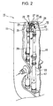
- FIG. 2 is a perspective view showing a jet pump installed in a downcomer portion in the reactor pressure vessel of FIG. 1 .
- FIG. 3 is an elevational view showing the jet pump of FIG. 2 .
- FIG. 4 is an enlarged perspective view showing an upper portion of the jet pump of FIG. 3 .
- a boiling water reactor 10 includes a reactor core 12 which is accommodated in a reactor pressure vessel 11. Steam -liquid separators 13 and steam dryers 14 are installed in such order above the reactor core 12.
- the reactor core 12 is surrounded by a cylindrical core shroud 16.
- An annular downcomer portion 17 is formed between the core shroud 16 and the reactor pressure vessel 11.
- the downcomer portion 17 includes a plurality of sets, e.g., ten sets of, twenty jet pumps 18.
- the jet pumps 18 are connected to an external reactor recirculation system (not shown) in the reactor pressure vessel 11, and configured to forcefully feed cooling water into the reactor core 12.
- a jet pump 18 includes a riser 20 serving as a cooling water supply pipe, a transition piece 21, an inlet mixer 22 constituting a pair of elbow parts, and diffusers 23.
- the transition piece 21 is integrally configured with an upper portion of the riser 20 to form a bifurcated branch portion at the top of the riser.
- transition piece posts 25, 25 are fixed to both sides of the bifurcated branch portion of the transition piece 21 so as to be opposed to each other and erected vertically upward.
- the pair of transition piece posts 25, 25 have pockets 26, 26 of engaging groove shape in their mutually-opposed inner surface sides. Both ends of jet pump beams 27, or plate spring members, made of a nickel-base alloy are inserted into and supported by the pockets 26, 26, whereby the jet pump beams 27 are laid across in a generally horizontal direction.
- the jet pump beams 27 are in contact with and support the top of the inlet mixer 22 forming the elbow parts so that the top of the inlet mixer 22 is pressed from above.
- the inlet mixer 22 is installed on a seal surface of the bifurcated portion of the transition piece 21 to form reversing channels of cooling water that rises through the riser 20.
- Both ends of the jet pump beams 27 are in surface contact with, engaged with, and supported by upper surfaces of the pockets 26, 26.
- Protrusions 28 with through-holes for having are formed on the inlet mixer 22.
- a vertical screw hole 29 (shown in FIG. 6 ) orthogonal to a beam axis direction is formed in the center of each jet pump beam 27.
- a male screw 31 of a head bolt made of a polygonal bolt such as a hex bolt is threadedly coupled with the vertical screw hole 29.
- An extremity (lower end) of the male screw 31 makes contact with and supports the top of the inlet mixer 22 so as to press the top.
- a predetermined axial force is thus applied to a head bolt 30 so that the inlet mixer 22 is fixed to the riser 20 by resilience of the jet pump beam 27 which is a plate spring member.
- the inlet mixer 22 is detachably installed onto the transition piece 21 at the top of the riser 20 by using bolt fixing devices 35 of the jet pump beams 27.
- FIG. 5 is a plan view showing a first embodiment of the bolt fixing device of a jet pump beam according to the present invention.
- FIG. 6 is a sectional elevational view showing the bolt fixing device of FIG. 5 .
- a bolt fixing device 35 includes a head bolt 30 which is threadedly coupled with a vertical screw hole 29 of a jet pump beam 27, a lock cap 36 serving as a moving member which is capable of integral rotation with a polygonal head portion 32 of the head bolt 30 and is axially movable up and down, a body housing 37 which can accommodate the lock cap 36 in a fixing position or a rotatable position selectively, and a spring member 40 serving as an elastic member which is accommodated in the body housing 37 and applies elastic force to the lock cap 36 toward an integral rotation side above.
- the lock cap 36 is fitted to and combined with the head bolt 30 which fixes the inlet mixer 22 to the riser 20, and is arranged inside the body housing 37.
- the body housing 37 includes an integrally-formed base plate 39 which is intended for installation onto the top (upper surface) 27a of the jet pump beam 27 via a washer 38.
- the base plate 39 is fixed to the top 27a of the jet pump beam 27 by positioning pins 41 and machine screws 42 such as flat head screws.
- FIG. 7 is a plan view showing the body housing of FIG. 6 .
- FIG. 8 is a partially sectional elevational view showing the body housing of FIG. 6 .
- FIG. 9 is an enlarged side view showing lower surface teeth of FIG. 8.
- FIG. 10 is an enlarged bottom view showing the lower surface teeth of FIG. 8 .
- a locking flange 37a is integrally formed on an inner peripheral side of the upper surface of the body housing 37.
- a plurality of downward, inclined lower surface teeth 44 as shown in FIGS. 9 and 10 are circumferentially formed on the lower surface of the locking flange 37a.
- a circular opening 37b is formed in the upper surface of the body housing 37.
- a sleeve portion 36c (shown in FIG. 12 ) of the lock cap 36 is arranged on the inner peripheral side of the opening 37b. Since the flange portion 36a of the lock cap 36 and the spring member 40 are arranged inside the body housing 37, the height dimension of the body housing 37 is determined in consideration of the heights of the flange portion 36a and the spring member 40.
- the body housing 37 has an outer diameter capable of handling by a not-shown handling device. Torque due to loosening of the bolt causes torsional stress on the barrel portion of the body housing 37.
- the barrel portion of the body housing 37 thus has a thickness satisfying allowable stress.
- a lower surface tooth 44 includes a vertical surface that extends vertically downward with respect to the direction of rotation of the head bolt 30 when the head bolt 30 loosens (hereinafter, referred to as the loosening direction of the head bolt 30) and an inclined surface that is inclined with respect to the direction of rotation of the head bolt 30 when the head bolt 30 tightens (hereinafter, referred to as the tightening direction of the head bolt 30), the vertical and inclined surfaces being formed with a horizontal surface therebetween.
- a plurality of such lower surface teeth 44 are formed along the circumferential direction.
- FIG. 11 is a plan view showing the lock cap of FIG. 6 .
- FIG. 12 is a partially sectional elevational view showing the lock cap of FIG. 6 .
- FIG. 13 is an enlarged side view showing upper surface teeth of FIG. 12 .
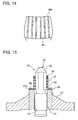
- FIG. 14 is an enlarged plan view showing the upper surface teeth of FIG. 12 .
- a hole 36b having a hexagonal shape similar to the outer shape of the head bolt 30 is formed in the inner peripheral side of the lock cap 36.
- the head bolt 30 having a hexagonal outer peripheral surface is fitted to the hexagonal hole 36b of the lock cap 36.
- the flange portion 36a extending radially outward as described above is integrally formed on the lock cap 36.
- a plurality of inclined upper surface teeth 45 to mesh with the lower surface teeth 44 of the body housing 37 are circumferentially formed on the upper surface of the flange portion 36a.
- the upper surface teeth 45 of the body housing 37 are formed in a serrated shape like the lower surface teeth 44.
- an upper surface tooth 45 includes a vertical surface that extends vertically upward with respect to the loosening direction of the head bolt 30 and an inclined surface that is inclined with respect to the tightening direction of the head bolt 30, the vertical and inclined surfaces being formed with a horizontal surface therebetween.
- a plurality of such upper surface teeth 45 are formed along the circumferential direction.
- the upper surface teeth 45 of the lock cap 36 and the lower surface teeth 44 of the body housing 37 are formed in serrated shapes and include vertical surfaces extending vertically that face each other in contact with each other when the head bolt 30 is rotated to be loosened.
- the sleeve portion 36c is configured to protrude vertically upward from the locking flange 37a of the body housing 37 when the lock cap 36 is pushed up by the elastic force of the spring member 40.
- the lock cap 36 and the body housing 37 are made of hard material such as a nickel-based alloy. At least the lower surface teeth 44 of the body housing 37 and the upper surface teeth 45 of the lock cap 36 are made of hard material.
- the average diameter and wire diameter of the spring member 40 are determined within the range of the limited space.
- the height of the body housing 37 is determined so that the spring member 40 has a height greater than or equal to its solid height when the lock cap 36 is pushed down. If elastic force needed to push up the lock cap 36 cannot be obtained, the body housing 37 is formed higher and the head bolt 30 longer to set dimensions at which the necessary elastic force of the spring member 40 can be obtained.
- An upper end of the spring member 40 is in contact with the bottom surface of the flange portion 36a of the lock cap 36.
- a lower end of the spring member 40 is supported by the upper surface of the washer 38. Since the lower end of the spring member 40 is supported by the washer 38, the spring member 40 is prevented from falling into the screw hole 29 of the jet pump beam 27. As a result, the spring member 40 can reliably push up the lock cap 36 by its elastic force.
- FIG. 15 is an elevational sectional view showing a state where the lock cap of FIG. 6 is pushed in.
- FIGS. 16(a), 16(b), 16(c), and 16(d) are enlarged views showing the order of meshing of the upper surface teeth and the lower surface teeth according to the first embodiment.
- FIG. 15 shows a state where, for example, an operator on an operation floor pushes in the sleeve portion 36c of the lock cap 36 protruding vertically upward from the upper surface of the body housing 37 by using a tool such as a not-shown hex wrench.
- the dimension from the upper surface of the body housing 37 to the position of the polygonal head portion 32 where the six sides of the head bolt 30 are formed constitutes a grip portion for applying tightening torque to the head bolt 30. Dimensions enough to apply torque shall be secured.
- the operator When tightening the head bolt 30, the operator starts to tighten the head bolt 30 by using a tool such as a not-shown hex wrench in the state shown in FIG. 15 .
- the lock cap 36 usually co-rotates with the head bolt 30.
- the sleeve portion 36c of the lock cap 36 is pushed in, as shown in FIG. 16(a) , the head bolt 30 can rotate without the lower surface teeth 44 of the body housing 37 and the upper surface teeth 45 of the lock cap 36 interfering with each other.
- the pressing force on the sleeve portion 36c of the lock cap 36 is removed (released) when certain torque occurs.
- the lock cap 36 is pushed vertically upward by the elastic force of the spring member 40 to a position where the upper surface teeth 45 of the lock cap 36 are in contact with the lower surface teeth 44 of the body housing 37.
- the lower surface teeth 44 and the upper surface teeth 45 make contact with each other in different states in the positional relationship of FIG. 16(b) or 16(c) , depending on the point in time when the sleeve portion 36c of the lock cap 36 is released.
- the lock cap 36 co-rotates with the head bolt 30 to start rotating in the loosening direction. As the rotation continues, the lower surface teeth 44 of the body housing 37 and the upper surface teeth 45 of the lock cap 36 come into the completely-meshing positional relationship of FIG. 16(d) .
- the tightening force of the jet pump beam 27 loosens from the maximum tightening force to the position where the teeth mesh with each other.
- the maximum amount of loosening needs to be within a tolerance range of the tightening force.
- the maximum amount of loosening is the tooth pitch. The tooth pitch is thus determined by converting the tolerance range of the tightening force of the head bolt 30 into an allowable rotation angle of the head bolt 30.
- the head bolt 30 can be easily and reliably locked against rotation when dismounting the inlet mixer 22 from the jet pump 18 or when reinstalling the inlet mixer 22 on the jet pump 18.
- the head bolt 30 can be easily and reliably fixed to the jet pump beam 27 by meshing the upper surface teeth 45 of the lock cap 36 with the lower surface teeth 44 of the body housing 37.
- the upper surface teeth 45 and the lower surface teeth 44 can be easily and reliably meshed with each other, the upper surface teeth 45 and the lower surface teeth 44 do not need precision machining. This can increase the machining efficiency.
- the lock cap 36 can be simply pushed down against the elastic force of the spring member 40 to unmesh the upper surface teeth 45 of the lock cap 36 from the lower surface teeth 44 of the body housing 37.
- the lock cap 36 can thus be simply and easily made rotatable with respect to the body housing 37.
- the head bolt 30 can be easily and reliably fixed and unfixed by operating the lock cap 36 to slide in the axial direction of the head bolt 30.
- the inlet mixer 22 is installed on the seat surface of the transition piece 21 on the upper portion of the riser 20 of the jet pump 18 as pressed and supported by the bolt fixing device 35 by utilizing the jet pump beam 27.
- the bolt fixing device 35 of the present embodiment mechanical rotation locking is provided when installing the inlet mixer 22 of the cooling water circulation jet pump 18 which is arranged in the downcomer portion 17 of the boiling water reactor 10.
- the head bolt 30 of the jet pump beam 27 thereby can be easily and accurately locked against rotation, and can be easily unlocked as well.
- the inlet mixer 22 when reinstalling the inlet mixer 22, the inlet mixer 22 can be easily dismounted and reinstalled in a short time.
- the head bolt 30 can be rotated without the teeth interfering with each other, which can reduce the wear of the teeth.
- the upper surface teeth 45 of the lock cap 36 and the lower surface teeth 44 of the body housing 37 are formed in a serrated shape, including vertical surfaces that extend vertically with respect to the loosening direction of the head bolt 30. This prevents the occurrence of a vertically downward force component on the spring member 40 due to the loosening torque of the head bolt 30.
- the upper surface teeth 45 of the lock cap 36 and the lower surface teeth 44 of the body housing 37 are prevented from accidental unmeshing.
- the vertical force of the spring member 40 always acts upward, which can improve the reliability as a bolt fixing device.
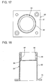
- FIG. 17 is a plan view showing a body housing in a second embodiment of the bolt fixing device of a jet pump beam according to the present invention.
- FIG. 18 is an elevational sectional view of FIG. 17 .
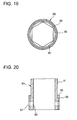
- FIG. 19 is a plan view showing a lock cap in the second embodiment of the bolt fixing device of a jet pump beam according to the present invention.
- FIG. 20 is an elevational sectional view of FIG. 19 .
- the body housing 37 and the lock cap 36 both have an integral structure, including a complicated tooth structure each.
- a body housing 50 and a lock cap 60 have a divided structure for improved tooth machinability.
- the body housing 50 is divided between a housing 52 on which a flange 51 is integrally formed and a tooth forming unit 55 which has lower surface teeth 56 formed on its lower end.
- a plurality of fixing holes 53 are formed in the housing 52.
- the lower surface teeth 56 are formed on the lower end of the tooth forming unit 55.
- the tooth forming unit 55 also has fixing holes 57 which are formed in portions that come to the same positions as the fixing holes 53 when the tooth forming unit 55 is combined with the housing 52.
- the housing 52 and the tooth forming unit 55 are coupled with each other by inserting fixing members such as a not-shown pin into the fixing holes 53 of the housing 52 and the fixing holes 53 of the tooth forming unit 55.
- the body housing 50 is configured to be divided between the housing 52 and the tooth forming unit 55, the lower surface teeth 56 can be machined with a relief.
- the lock cap 60 is divided between a cap body 61 and a tooth forming unit 65.
- a plurality of fixing holes 62 are formed in the cap body 61.
- Upper surface teeth 66 are formed on the upper end of the tooth forming unit 65.
- the tooth forming unit 65 also has fixing holes 67 which are formed in portions that come to the same positions as the fixing holes 62 when the tooth forming unit 65 is combined with the cap body 61.
- the cap body 61 and the tooth forming unit 65 are coupled with each other by inserting fixing members such as a not-shown pin into the fixing holes 62 of the cap body 61 and the fixing holes 67 of the tooth forming unit 55.
- the lock cap 60 is configured to be divided between the cap body 61 and the tooth forming unit 65, the upper surface teeth 66 can be machined with a relief.
- the body housing 50 and the lock cap 60 each have a divided structure, which increases the height dimensions.
- the height dimension of the head bolt 30 is thus desirably increased to secure dimensions for applying torque because the portion from the upper surface of the body housing 50 to the position where the polygonal head portion 32 of the head bolt 30 is formed serves as the grip portion for applying tightening torque.
- the body housing 50 and the lock cap 60 include the tooth forming units 55 and 65 of divided structure, respectively. This can improve the machinability of the body housing 50 and the lock cap 60.
- FIG. 21 is an elevational sectional view showing a third embodiment of the bolt fixing device of a jet pump beam according to the present invention.
- the base plate 39 of the body housing 37 is fixed to the jet pump beam 27 by the positioning pins 41 and the machine screws 42.
- the present embodiment includes a base plate 75.
- a body housing 70 is fixed to the base plate 75.
- the base plate 75 is fixed to the jet pump beam 27 by the positioning pins 41 and the machine screws 42.
- FIG. 22 is a plan view showing the body housing of FIG. 21 .
- FIG. 23 is a partially sectional elevational view showing the body housing of FIG. 21 .
- a locking flange 70a is integrally formed on the inner peripheral side of the upper surface of the body housing 70.
- a plurality of downward, inclined lower surface teeth 44 are circumferentially formed on the lower surface of the locking flange 70a.
- a circular opening 70b is formed in the upper surface of the body housing 70.
- the lock cap 36 is arranged inside the opening 70b.
- Tabs 71 extending radially outward are formed on the body housing 70 in circumferentially opposite positions.
- FIG. 24 is a plan view showing the base plate of FIG. 21 .
- FIG. 25 is a partially sectional elevational view showing the base plate of FIG. 21 .
- a circular stepped hole 75a having upper and lower, two stages of diameters is formed in the center of the base plate 75.
- Notches 76 are formed in the underside of the base plate 75 in the same circumferential positions as those of the tabs 71 of the body housing 70.
- the lower surface of the upper stage of the stepped hole 75a in the base plate 75 holds down a tapered portion in a lower part of the body housing 70, whereby the force of the spring member 40 acting vertically upward is prevented from lifting.
- the tabs 71 formed on the lower part of the body housing 70 fit to the notches 76 in the base plate 75. This prevents force acting in the direction of rotation due to the loosening torque of the head bolt 30.
- the tabs 71 of the body housing 70 and the notches 76 in the base plate 75 may have a difference in width, without the tabs 71 fitting to the notches 76.
- the difference is set to allow circumferential rotation of the body housing 70.
- the amount of the difference between the widths can be adjusted to arbitrarily adjust the amount of rotation of the body housing 70 in the circumferential direction.
- the foregoing first embodiment is configured so that the positional relationship between the lower surface teeth 44 of the body housing 37 and the upper surface teeth 45 of the lock cap 36 cannot be adjusted after the tightening of the head bolt 30.
- the teeth mesh with each other when loosening torque occurs.
- the present embodiment allows rotation of the body housing 70.
- the tightening of the head bolt 30 can thus be completed with the lower surface teeth 44 of the body housing 70 and the upper surface teeth 45 of the lock cap 36 fully meshed with each other.
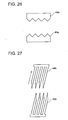
- FIG. 26 is an enlarged view showing upper surface teeth and lower surface teeth in a fourth embodiment of the bolt fixing device of a jet pump beam according to the present invention.
- the lower surface teeth 44 of the body housing 37 and the upper surface teeth 45 of the lock cap 36 are formed in a serrated shape.
- the lower surface teeth 44a of the body housing 37 and the upper surface teeth 45a of the lock cap 36 are formed in a triangular shape having equal angles of inclination.
- the lower surface teeth 44a and the upper surface teeth 45a have inclined surfaces that are inclined both in the tightening direction and the loosening direction.
- the upper surface teeth 45a of the lock cap 36 and the lower surface teeth 44a of the body housing 37 include forwardly inclined surfaces that face each other in contact with each other when the head bolt 30 is rotated to be loosened and when the head bolt 30 is rotated to be tightened.
- the inclined surfaces in the loosening direction of the head bolt 30 produce vertically downward force when loosening torque occurs. Loosening can be prevented by increasing the elastic force of the spring member 40.
- the lower surface teeth 44a and the upper surface teeth 45a have the inclined surfaces inclined both in the tightening direction of the head bolt 30 and the loosening direction of the head bolt 30.
- a rotational load can be applied to force rotation in the tightening direction and the loosening direction even in a meshing state.
- FIG. 27 is an enlarged view showing upper surface teeth and lower surface teeth in a fifth embodiment of the bolt fixing device of a jet pump beam according to the present invention.
- the lower surface teeth 44b of the body housing 37 and the upper surface teeth 45b of the lock cap 36 are formed in parallel with each other and so as to be inclined in the tightening direction of the head bolt 30.
- the pitches of the lower surface teeth 44b and the upper surface teeth 45b determine the tolerance of the tightening force. Even if loosening occurs as much as a pitch of the lower surface teeth 44b and the upper surface teeth 45b, turning force is applied in the tightening direction in the process of being pushed up by the elastic force of the spring member 40.
- the lower surface teeth 44b and the upper surface teeth 45b are formed in parallel with each other and inclined in the tightening direction of the head bolt 30. Even if loosening occurs as much as a tooth pitch, the amount of loosening can be reduced by the application of the turning force in the tightening direction.
- the foregoing embodiments have dealt with the cases where a compression spring is used as the spring member 40.
- a compression spring is used as the spring member 40.
- this is not restrictive.
- a leaf spring, rubber, and other elastic members may be used.
- a plurality of upper surface teeth 45, 45a, 45b, or 66 are formed on the upper surface of the flange portion 36a, or the tooth forming unit 65 of the lock cap 36, 60 a plurality of lower surface teeth 44, 44a, 44b, or 56 are formed on the lower surface of the locking flange 37a 70a or tooth forming unit 55 of the body housing 37, 70 50 and the teeth are meshed with each other.
- a pin may be attached to the upper surface of the flange portion 36a of the lock cap 36 to form an engaging portion, and a hole serving as a to-be-engaged portion to be engaged with the pin may be formed in the lower surface of the locking flange 37a of the body housing 37.
- the engaging portion and the to-be-engaged portion may be such that the engaging portion is a hole and the to-be-engaged portion is a pin.
- the engaging portion and the to-be-engaged portion are not limited to a combination of a pin and a hole, and may have other shapes capable of fitting, such as a recess and a projection.
Landscapes
- Engineering & Computer Science (AREA)
- General Engineering & Computer Science (AREA)
- Physics & Mathematics (AREA)
- Mechanical Engineering (AREA)
- Plasma & Fusion (AREA)
- High Energy & Nuclear Physics (AREA)
- Fluid Mechanics (AREA)
- Jet Pumps And Other Pumps (AREA)
Abstract
Description
- Embodiments of the present invention relate to a jet pump installed in a downcomer portion of a reactor pressure vessel of a boiling water reactor, and a bolt fixing device of a jet pump beam.
- A boiling water reactor is typically equipped with an external circulation system for forcefully feeding coolant into a reactor core. A plurality of sets of jet pumps connected to the external circulation system are arranged in an annular downcomer portion between a core shroud and a reactor pressure vessel.
- A jet pump mainly includes a riser, a diffuser, and an inlet mixer. To install the jet pump in the reactor pressure vessel, the riser, the diffuser, and the inlet mixer are installed in such order. The diffuser is welded and mounted onto a baffle plate in the reactor pressure vessel.
- The inlet mixer is installed by passing a lower end of the inlet mixer through a riser bracket attached to a side surface of the riser pipe, and then inserting the lower end into an opening in the top of the diffuser. A seat surface of an elbow part of the inlet mixer is placed on the top of the riser. A head bolt of a jet pump beam for installing the inlet mixer is then tightened to fix the inlet mixer to the upper portion of the riser.
- After the head bolt is tightened to install the inlet mixer on the top of the riser via the jet pump beam, the head bolt threadedly coupled with the jet pump beam needs to be locked against rotation.
- Among conventional bolt fixing devices for a jet pump beam there is a technique, for example, described in Patent Document 1. The technique includes providing an axially-slidable, integrally-rotating lock cap on a polygonal head portion of the head bolt, and arranging a body housing accommodating the lock cap on an upper surface of the jet pump beam. A plurality of tapered external teeth are formed on an outer peripheral side surface of the lock cap. The body housing has internal tooth-like grooves to selectively mesh with the external teeth of the lock cap. The external teeth of the lock cap and the internal tooth-like grooves are meshed with each other, whereby the head bolt of the jet pump beam is fixed.
- Patent Document 1: Japanese Patent Application Laid-Open Publication No.
2010-14674 - According to the technique described in Patent Document 1, the lock cap needs to be moved upward to mesh the external teeth with the internal tooth-like grooves of the body housing. The meshing may be difficult unless the dimensions of the external teeth of the lock cap and the internal tooth-like grooves of the body housing are accurately set. Since the dimensions of the external teeth of the lock cap and the internal tooth-like grooves of the body housing need to be accurately set, the external teeth of the lock cap and the internal tooth-like grooves of the body housing both need precise machining.
- An object of embodiments of the present invention is to provide a jet pump and a bolt fixing device of a jet pump beam by which a head bolt of the jet pump beam can be easily and reliably locked against rotation when installing an inlet mixer.
- In order to achieve the above-mentioned object, according to an embodiment, there is provided a bolt fixing device of a jet pump beam for fixing a head bolt of a jet pump beam pressing an inlet mixer from vertically above, the inlet mixer being arranged on an upper portion of a riser of a jet pump of a boiling water reactor and forming a reversing channel of cooling water, the bolt fixing device of a jet pump beam comprising: a lock cap that fits to a polygonal head portion of the head bolt, is movable in a vertical axis direction, and is integrally rotatable with the head bolt; a body housing that accommodates the lock cap and is arranged on an upper surface of the jet pump beam; and an elastic member that is arranged in the body housing below the lock cap and applies vertically upward elastic force to the lock cap, the lock cap being pushed up by the elastic force of the elastic member so that a plurality of upper surface teeth circumferentially formed on an upper surface of a flange of the lock cap mesh with a plurality of lower surface teeth circumferentially formed on a lower surface of a locking flange of the body housing, whereby the head bolt of the jet pump beam is fixed.
- Furthermore in order to achieve the above-mentioned object, according to an embodiment, there is provided a bolt fixing device of a jet pump beam for fixing a head bolt of a jet pump beam pressing an inlet mixer from vertically above, the inlet mixer being arranged on an upper portion of a riser of a jet pump of a boiling water reactor and forming a reversing channel of cooling water, the bolt fixing device of a jet pump beam comprising: a lock cap that fits to a polygonal head portion of the head bolt, is movable in a vertical axial direction, and is integrally rotatable with the head bolt; a body housing that accommodates the lock cap and is arranged on an upper surface of the jet pump beam; and an elastic member that is arranged in the body housing below the lock cap and applies vertically upward elastic force to the lock cap, the lock cap being pushed up by the elastic force of the elastic member so that an engaging portion circumferentially formed on an upper surface of a flange of the lock cap is engaged with a to-be-engaged portion circumferentially formed on a lower surface of a locking flange of the body housing, whereby the head bolt of the jet pump beam is fixed.
- Furthermore in order to achieve the above-mentioned object, according to an embodiment, there is provided a jet pump of a boiling water reactor including a bolt fixing device of a jet pump beam for fixing a head bolt of a jet pump beam pressing an inlet mixer from vertically above, the inlet mixer being arranged on an upper portion of a riser and forming a reversing channel of cooling water, the bolt fixing device of a jet pump beam comprising: a lock cap that fits to a polygonal head portion of the head bolt, is movable in a vertical axial direction, and is integrally rotatable with the head bolt; a body housing that accommodates the lock cap and is arranged on an upper surface of the jet pump beam; and an elastic member that is arranged in the body housing below the lock cap and applies vertically upward elastic force to the lock cap, the lock cap being pushed up by the elastic force of the elastic member so that a plurality of upper surface teeth circumferentially formed on an upper surface of a flange of the lock cap mesh with a plurality of lower surface teeth circumferentially formed on a lower surface of a locking flange of the body housing, whereby the head bolt of the jet pump beam is fixed.
- According to the embodiments of the present invention, the bolt of the jet pump beam can be easily and reliably locked against rotation when installing the inlet mixer.
-
-
FIG. 1 is an elevational sectional configuration diagram showing an overview of a reactor pressure vessel of a boiling water reactor to which the present invention is applied. -
FIG. 2 is a perspective view showing a jet pump installed in a downcomer portion in the reactor pressure vessel ofFIG. 1 . -
FIG. 3 is an elevational view showing the jet pump ofFIG. 2 . -
FIG. 4 is an enlarged perspective view showing an upper portion of the jet pump ofFIG. 3 . -
FIG. 5 is a plan view showing a first embodiment of the bolt fixing device of a jet pump beam according to the present invention. -
FIG. 6 is an elevational sectional view showing the bolt fixing device ofFIG. 5 . -
FIG. 7 is a plan view showing a body housing ofFIG. 6 . -
FIG. 8 is a partially sectional elevational view showing the body housing ofFIG. 6 . -
FIG. 9 is an enlarged side view showing lower surface teeth ofFIG. 8 . -
FIG. 10 is an enlarged bottom view showing the lower surface teeth ofFIG. 8 . -
FIG. 11 is a plan view showing a lock cap ofFIG. 6 . -
FIG. 12 is a partially sectional elevational view showing the lock cap ofFIG. 6 . -
FIG. 13 is an enlarged side view showing upper surface teeth ofFIG. 12 . -
FIG. 14 is an enlarged plan view showing the upper surface teeth ofFIG. 12 . -
FIG. 15 is an elevational sectional view showing a state where the lock cap ofFIG. 6 is pushed in. -
FIGS. 16(a), 16(b), 16(c), and 16(d) are enlarged views showing the order of meshing of the upper surface teeth and the lower surface teeth according to the first embodiment. -
FIG. 17 is a plan view showing a body housing in a second embodiment of the bolt fixing device of a jet pump beam according to the present invention. -
FIG. 18 is an elevational sectional view ofFIG. 17 . -
FIG. 19 is a plan view showing a lock cap in the second embodiment of the bolt fixing device of a jet pump beam according to the present invention. -
FIG. 20 is an elevational sectional view ofFIG. 19 . -
FIG. 21 is an elevational sectional view showing a third embodiment of the bolt fixing device of a jet pump beam according to the present invention. -
FIG. 22 is a plan view showing a body housing ofFIG. 21 . -
FIG. 23 is a partially sectional elevational view showing the body housing ofFIG. 21 . -
FIG. 24 is a plan view showing a base plate ofFIG. 21 . -
FIG. 25 is a partially sectional elevational view showing the base plate ofFIG. 21 . -
FIG. 26 is an enlarged view showing upper surface teeth and lower surface teeth in a fourth embodiment of the bolt fixing device of a jet pump beam according to the present invention. -
FIG. 27 is an enlarged view showing upper surface teeth and lower surface teeth in a fifth embodiment of the bolt fixing device of a jet pump beam according to the present invention. - Embodiments of the bolt fixing device of a jet pump beam according to the present invention will be described below with reference to the drawings.
- A configuration of a reactor pressure vessel and a jet pump will initially be described.
-
FIG. 1 is an elevational sectional configuration diagram showing a general configuration of a reactor pressure vessel of a boiling water reactor to which the present invention is applied.FIG. 2 is a perspective view showing a jet pump installed in a downcomer portion in the reactor pressure vessel ofFIG. 1 .FIG. 3 is an elevational view showing the jet pump ofFIG. 2 .FIG. 4 is an enlarged perspective view showing an upper portion of the jet pump ofFIG. 3 . - As shown in
FIG. 1 , a boilingwater reactor 10 includes areactor core 12 which is accommodated in areactor pressure vessel 11. Steam -liquid separators 13 andsteam dryers 14 are installed in such order above thereactor core 12. - The
reactor core 12 is surrounded by acylindrical core shroud 16. Anannular downcomer portion 17 is formed between thecore shroud 16 and thereactor pressure vessel 11. Thedowncomer portion 17 includes a plurality of sets, e.g., ten sets of, twenty jet pumps 18. The jet pumps 18 are connected to an external reactor recirculation system (not shown) in thereactor pressure vessel 11, and configured to forcefully feed cooling water into thereactor core 12. - As shown in
FIGS. 2 and3 , ajet pump 18 includes ariser 20 serving as a cooling water supply pipe, atransition piece 21, aninlet mixer 22 constituting a pair of elbow parts, anddiffusers 23. Thetransition piece 21 is integrally configured with an upper portion of theriser 20 to form a bifurcated branch portion at the top of the riser. - As shown in
FIGS. 3 and4 , transition piece posts 25, 25 are fixed to both sides of the bifurcated branch portion of thetransition piece 21 so as to be opposed to each other and erected vertically upward. The pair of transition piece posts 25, 25 havepockets pockets - The jet pump beams 27 are in contact with and support the top of the
inlet mixer 22 forming the elbow parts so that the top of theinlet mixer 22 is pressed from above. Theinlet mixer 22 is installed on a seal surface of the bifurcated portion of thetransition piece 21 to form reversing channels of cooling water that rises through theriser 20. - Both ends of the jet pump beams 27 are in surface contact with, engaged with, and supported by upper surfaces of the
pockets Protrusions 28 with through-holes for having are formed on theinlet mixer 22. - A vertical screw hole 29 (shown in
FIG. 6 ) orthogonal to a beam axis direction is formed in the center of eachjet pump beam 27. Amale screw 31 of a head bolt made of a polygonal bolt such as a hex bolt is threadedly coupled with thevertical screw hole 29. An extremity (lower end) of themale screw 31 makes contact with and supports the top of theinlet mixer 22 so as to press the top. A predetermined axial force is thus applied to ahead bolt 30 so that theinlet mixer 22 is fixed to theriser 20 by resilience of thejet pump beam 27 which is a plate spring member. - The
inlet mixer 22 is detachably installed onto thetransition piece 21 at the top of theriser 20 by usingbolt fixing devices 35 of the jet pump beams 27. - Next, the
bolt fixing device 35 of the jet pump beams 27 according to the present embodiment will be described.FIG. 5 is a plan view showing a first embodiment of the bolt fixing device of a jet pump beam according to the present invention.FIG. 6 is a sectional elevational view showing the bolt fixing device ofFIG. 5 . - As shown in
FIGS. 5 and6 , abolt fixing device 35 includes ahead bolt 30 which is threadedly coupled with avertical screw hole 29 of ajet pump beam 27, alock cap 36 serving as a moving member which is capable of integral rotation with apolygonal head portion 32 of thehead bolt 30 and is axially movable up and down, abody housing 37 which can accommodate thelock cap 36 in a fixing position or a rotatable position selectively, and aspring member 40 serving as an elastic member which is accommodated in thebody housing 37 and applies elastic force to thelock cap 36 toward an integral rotation side above. - In other words, the
lock cap 36 is fitted to and combined with thehead bolt 30 which fixes theinlet mixer 22 to theriser 20, and is arranged inside thebody housing 37. - The
body housing 37 includes an integrally-formedbase plate 39 which is intended for installation onto the top (upper surface) 27a of thejet pump beam 27 via awasher 38. Thebase plate 39 is fixed to the top 27a of thejet pump beam 27 by positioningpins 41 andmachine screws 42 such as flat head screws. - Next, the configuration of the
body housing 37 will be described in detail. -
FIG. 7 is a plan view showing the body housing ofFIG. 6 .FIG. 8 is a partially sectional elevational view showing the body housing ofFIG. 6 .FIG. 9 is an enlarged side view showing lower surface teeth ofFIG. 8. FIG. 10 is an enlarged bottom view showing the lower surface teeth ofFIG. 8 . - As shown in
FIGS. 7 and8 , a lockingflange 37a is integrally formed on an inner peripheral side of the upper surface of thebody housing 37. A plurality of downward, inclinedlower surface teeth 44 as shown inFIGS. 9 and 10 are circumferentially formed on the lower surface of the lockingflange 37a. - As shown in
FIGS. 7 and8 , acircular opening 37b is formed in the upper surface of thebody housing 37. Asleeve portion 36c (shown inFIG. 12 ) of thelock cap 36 is arranged on the inner peripheral side of theopening 37b. Since theflange portion 36a of thelock cap 36 and thespring member 40 are arranged inside thebody housing 37, the height dimension of thebody housing 37 is determined in consideration of the heights of theflange portion 36a and thespring member 40. - The
body housing 37 has an outer diameter capable of handling by a not-shown handling device. Torque due to loosening of the bolt causes torsional stress on the barrel portion of thebody housing 37. The barrel portion of thebody housing 37 thus has a thickness satisfying allowable stress. - As shown in
FIGS. 9 and 10 , thelower surface teeth 44 of thebody housing 37 are formed in a serrated shape. Specifically, alower surface tooth 44 includes a vertical surface that extends vertically downward with respect to the direction of rotation of thehead bolt 30 when thehead bolt 30 loosens (hereinafter, referred to as the loosening direction of the head bolt 30) and an inclined surface that is inclined with respect to the direction of rotation of thehead bolt 30 when thehead bolt 30 tightens (hereinafter, referred to as the tightening direction of the head bolt 30), the vertical and inclined surfaces being formed with a horizontal surface therebetween. A plurality of suchlower surface teeth 44 are formed along the circumferential direction. - Next, the configuration of the
lock cap 36 will be described in detail. -
FIG. 11 is a plan view showing the lock cap ofFIG. 6 .FIG. 12 is a partially sectional elevational view showing the lock cap ofFIG. 6 .FIG. 13 is an enlarged side view showing upper surface teeth ofFIG. 12 .FIG. 14 is an enlarged plan view showing the upper surface teeth ofFIG. 12 . - As shown in
FIGS. 11 and 12 , ahole 36b having a hexagonal shape similar to the outer shape of thehead bolt 30 is formed in the inner peripheral side of thelock cap 36. Thehead bolt 30 having a hexagonal outer peripheral surface is fitted to thehexagonal hole 36b of thelock cap 36. When thelock cap 36 is combined with thebody housing 37, thesleeve portion 36c of thelock cap 36 is positioned inside thebody housing 37. - The
flange portion 36a extending radially outward as described above is integrally formed on thelock cap 36. A plurality of inclinedupper surface teeth 45 to mesh with thelower surface teeth 44 of thebody housing 37 are circumferentially formed on the upper surface of theflange portion 36a. When thelock cap 36 is pushed up by the elastic force of thespring member 40, thelower surface teeth 44 of thebody housing 37 and theupper surface teeth 45 of thelock cap 36 do mesh with each other to fix thehead bolt 30, whereby thehead bolt 30 can be locked against rotation. - As shown in
FIGS. 13 and14 , theupper surface teeth 45 of thebody housing 37 are formed in a serrated shape like thelower surface teeth 44. Specifically, like thelower surface teeth 44, anupper surface tooth 45 includes a vertical surface that extends vertically upward with respect to the loosening direction of thehead bolt 30 and an inclined surface that is inclined with respect to the tightening direction of thehead bolt 30, the vertical and inclined surfaces being formed with a horizontal surface therebetween. A plurality of suchupper surface teeth 45 are formed along the circumferential direction. In other words, theupper surface teeth 45 of thelock cap 36 and thelower surface teeth 44 of thebody housing 37 are formed in serrated shapes and include vertical surfaces extending vertically that face each other in contact with each other when thehead bolt 30 is rotated to be loosened. - The
sleeve portion 36c is configured to protrude vertically upward from the lockingflange 37a of thebody housing 37 when thelock cap 36 is pushed up by the elastic force of thespring member 40. - If, for example, an operator on an operation floor pushes down the protruding
sleeve portion 36c to push down thespring member 40 against its elastic force by using a tool such as a not-shown hex wrench, thelock cap 36 slides vertically downward. This unmeshes and unlocks theupper surface teeth 45 of thelock cap 36 from thelower surface teeth 44 of thebody housing 37. As a result, thelock cap 36 co-rotating with thehead bolt 30 is unlocked, and thehead bolt 30 becomes rotatable without meshing with thelower surface teeth 44 of thebody housing 37. - The
lock cap 36 and thebody housing 37 are made of hard material such as a nickel-based alloy. At least thelower surface teeth 44 of thebody housing 37 and theupper surface teeth 45 of thelock cap 36 are made of hard material. - Since the
spring member 40 is arranged between the outer periphery of thehead bolt 30 and the inner periphery of thebody housing 37, the average diameter and wire diameter of thespring member 40 are determined within the range of the limited space. The height of thebody housing 37 is determined so that thespring member 40 has a height greater than or equal to its solid height when thelock cap 36 is pushed down. If elastic force needed to push up thelock cap 36 cannot be obtained, the thebody housing 37 is formed higher and thehead bolt 30 longer to set dimensions at which the necessary elastic force of thespring member 40 can be obtained. - An upper end of the
spring member 40 is in contact with the bottom surface of theflange portion 36a of thelock cap 36. A lower end of thespring member 40 is supported by the upper surface of thewasher 38. Since the lower end of thespring member 40 is supported by thewasher 38, thespring member 40 is prevented from falling into thescrew hole 29 of thejet pump beam 27. As a result, thespring member 40 can reliably push up thelock cap 36 by its elastic force. - Next, an operation of the present embodiment will be described.
-
FIG. 15 is an elevational sectional view showing a state where the lock cap ofFIG. 6 is pushed in.FIGS. 16(a), 16(b), 16(c), and 16(d) are enlarged views showing the order of meshing of the upper surface teeth and the lower surface teeth according to the first embodiment. -
FIG. 15 shows a state where, for example, an operator on an operation floor pushes in thesleeve portion 36c of thelock cap 36 protruding vertically upward from the upper surface of thebody housing 37 by using a tool such as a not-shown hex wrench. - As shown in
FIG. 15 , the dimension from the upper surface of thebody housing 37 to the position of thepolygonal head portion 32 where the six sides of thehead bolt 30 are formed constitutes a grip portion for applying tightening torque to thehead bolt 30. Dimensions enough to apply torque shall be secured. - When tightening the
head bolt 30, the operator starts to tighten thehead bolt 30 by using a tool such as a not-shown hex wrench in the state shown inFIG. 15 . Thelock cap 36 usually co-rotates with thehead bolt 30. When thesleeve portion 36c of thelock cap 36 is pushed in, as shown inFIG. 16(a) , thehead bolt 30 can rotate without thelower surface teeth 44 of thebody housing 37 and theupper surface teeth 45 of thelock cap 36 interfering with each other. - After the start of the tightening of the
head bolt 30, the pressing force on thesleeve portion 36c of thelock cap 36 is removed (released) when certain torque occurs. When the pressing force on thesleeve portion 36c of thelock cap 36 is removed, thelock cap 36 is pushed vertically upward by the elastic force of thespring member 40 to a position where theupper surface teeth 45 of thelock cap 36 are in contact with thelower surface teeth 44 of thebody housing 37. Here, thelower surface teeth 44 and theupper surface teeth 45 make contact with each other in different states in the positional relationship ofFIG. 16(b) or 16(c) , depending on the point in time when thesleeve portion 36c of thelock cap 36 is released. - After the pressing force on the
sleeve portion 36c of thelock cap 36 is removed, the tightening of thehead bolt 30 is started again. Thehead bolt 30 is tightened until prescribed torque is obtained. Here, the states ofFIGS. 16(b) and 16(c) are repeated to reach the prescribed torque. - After the tightening of the
head bolt 30, the operator cannot get the positional relationship between thelower surface teeth 44 of thebody housing 37 and theupper surface teeth 45 of thelock cap 36. The operator thus ends the tightening in a state where thehead bolt 30 is tightened with the needed torque, which is shown inFIG. 16(b) or 16(c) . Thelower surface teeth 44 of thebody housing 37 and theupper surface teeth 45 of thelock cap 36 do not always mesh completely with each other. - However, if the
head bolt 30 undergoes loosening torque, thelock cap 36 co-rotates with thehead bolt 30 to start rotating in the loosening direction. As the rotation continues, thelower surface teeth 44 of thebody housing 37 and theupper surface teeth 45 of thelock cap 36 come into the completely-meshing positional relationship ofFIG. 16(d) . - Assuming that the foregoing prescribed torque is the maximum tightening force of the
jet pump beam 27, the tightening force of thejet pump beam 27 loosens from the maximum tightening force to the position where the teeth mesh with each other. To obtain a minimum tightening torque in such a state, the maximum amount of loosening needs to be within a tolerance range of the tightening force. The maximum amount of loosening is the tooth pitch. The tooth pitch is thus determined by converting the tolerance range of the tightening force of thehead bolt 30 into an allowable rotation angle of thehead bolt 30. - In such a manner, according to the present embodiment, the
head bolt 30 can be easily and reliably locked against rotation when dismounting theinlet mixer 22 from thejet pump 18 or when reinstalling theinlet mixer 22 on thejet pump 18. - The
head bolt 30 can be easily and reliably fixed to thejet pump beam 27 by meshing theupper surface teeth 45 of thelock cap 36 with thelower surface teeth 44 of thebody housing 37. Incidentally, since theupper surface teeth 45 and thelower surface teeth 44 can be easily and reliably meshed with each other, theupper surface teeth 45 and thelower surface teeth 44 do not need precision machining. This can increase the machining efficiency. - To unfix the
head bolt 30, thelock cap 36 can be simply pushed down against the elastic force of thespring member 40 to unmesh theupper surface teeth 45 of thelock cap 36 from thelower surface teeth 44 of thebody housing 37. Thelock cap 36 can thus be simply and easily made rotatable with respect to thebody housing 37. Thehead bolt 30 can be easily and reliably fixed and unfixed by operating thelock cap 36 to slide in the axial direction of thehead bolt 30. - In such a manner, according to the
bolt fixing device 35 of thejet pump beam 27 of the present embodiment, theinlet mixer 22 is installed on the seat surface of thetransition piece 21 on the upper portion of theriser 20 of thejet pump 18 as pressed and supported by thebolt fixing device 35 by utilizing thejet pump beam 27. - According to the
bolt fixing device 35 of the present embodiment, mechanical rotation locking is provided when installing theinlet mixer 22 of the cooling watercirculation jet pump 18 which is arranged in thedowncomer portion 17 of the boilingwater reactor 10. Thehead bolt 30 of thejet pump beam 27 thereby can be easily and accurately locked against rotation, and can be easily unlocked as well. - According to the present embodiment, when reinstalling the
inlet mixer 22, theinlet mixer 22 can be easily dismounted and reinstalled in a short time. Thehead bolt 30 can be rotated without the teeth interfering with each other, which can reduce the wear of the teeth. - Moreover, according to the present embodiment, the
upper surface teeth 45 of thelock cap 36 and thelower surface teeth 44 of thebody housing 37 are formed in a serrated shape, including vertical surfaces that extend vertically with respect to the loosening direction of thehead bolt 30. This prevents the occurrence of a vertically downward force component on thespring member 40 due to the loosening torque of thehead bolt 30. - Consequently, according to the present embodiment, the
upper surface teeth 45 of thelock cap 36 and thelower surface teeth 44 of thebody housing 37 are prevented from accidental unmeshing. The vertical force of thespring member 40 always acts upward, which can improve the reliability as a bolt fixing device. -
FIG. 17 is a plan view showing a body housing in a second embodiment of the bolt fixing device of a jet pump beam according to the present invention.FIG. 18 is an elevational sectional view ofFIG. 17 .FIG. 19 is a plan view showing a lock cap in the second embodiment of the bolt fixing device of a jet pump beam according to the present invention.FIG. 20 is an elevational sectional view ofFIG. 19 . - In the following embodiment, a configuration, operation, and effects different from those of the foregoing first embodiment will be described. A redundant description is omitted. The same applies to the other embodiments.
- In the foregoing first embodiment, the
body housing 37 and thelock cap 36 both have an integral structure, including a complicated tooth structure each. In the present embodiment, abody housing 50 and alock cap 60 have a divided structure for improved tooth machinability. - As shown in
FIGS. 17 and 18 , thebody housing 50 is divided between ahousing 52 on which aflange 51 is integrally formed and atooth forming unit 55 which haslower surface teeth 56 formed on its lower end. A plurality of fixingholes 53 are formed in thehousing 52. - The
lower surface teeth 56 are formed on the lower end of thetooth forming unit 55. Thetooth forming unit 55 also has fixingholes 57 which are formed in portions that come to the same positions as the fixing holes 53 when thetooth forming unit 55 is combined with thehousing 52. - The
housing 52 and thetooth forming unit 55 are coupled with each other by inserting fixing members such as a not-shown pin into the fixing holes 53 of thehousing 52 and the fixing holes 53 of thetooth forming unit 55. - Since the
body housing 50 is configured to be divided between thehousing 52 and thetooth forming unit 55, thelower surface teeth 56 can be machined with a relief. - As shown in
FIGS. 19 and 20 , thelock cap 60 is divided between acap body 61 and atooth forming unit 65. A plurality of fixingholes 62 are formed in thecap body 61. -
Upper surface teeth 66 are formed on the upper end of thetooth forming unit 65. Thetooth forming unit 65 also has fixingholes 67 which are formed in portions that come to the same positions as the fixing holes 62 when thetooth forming unit 65 is combined with thecap body 61. - The
cap body 61 and thetooth forming unit 65 are coupled with each other by inserting fixing members such as a not-shown pin into the fixing holes 62 of thecap body 61 and the fixing holes 67 of thetooth forming unit 55. - Since the
lock cap 60 is configured to be divided between thecap body 61 and thetooth forming unit 65, theupper surface teeth 66 can be machined with a relief. - In the present embodiment, the
body housing 50 and thelock cap 60 each have a divided structure, which increases the height dimensions. The height dimension of thehead bolt 30 is thus desirably increased to secure dimensions for applying torque because the portion from the upper surface of thebody housing 50 to the position where thepolygonal head portion 32 of thehead bolt 30 is formed serves as the grip portion for applying tightening torque. - As described above, according to the present embodiment, the
body housing 50 and thelock cap 60 include thetooth forming units body housing 50 and thelock cap 60. -
FIG. 21 is an elevational sectional view showing a third embodiment of the bolt fixing device of a jet pump beam according to the present invention. - In the foregoing first embodiment, the
base plate 39 of thebody housing 37 is fixed to thejet pump beam 27 by the positioning pins 41 and the machine screws 42. - As shown in
FIG. 21 , the present embodiment includes abase plate 75. Abody housing 70 is fixed to thebase plate 75. Thebase plate 75 is fixed to thejet pump beam 27 by the positioning pins 41 and the machine screws 42. - Next, the configuration of the
body housing 70 will be described in detail. -
FIG. 22 is a plan view showing the body housing ofFIG. 21 .FIG. 23 is a partially sectional elevational view showing the body housing ofFIG. 21 . - As shown in
FIGS. 22 and23 , a lockingflange 70a is integrally formed on the inner peripheral side of the upper surface of thebody housing 70. A plurality of downward, inclinedlower surface teeth 44 are circumferentially formed on the lower surface of the lockingflange 70a. - As shown in
FIGS. 22 and23 , acircular opening 70b is formed in the upper surface of thebody housing 70. Thelock cap 36 is arranged inside theopening 70b.Tabs 71 extending radially outward are formed on thebody housing 70 in circumferentially opposite positions. - Next, the configuration of the
base plate 75 will be described in detail. -
FIG. 24 is a plan view showing the base plate ofFIG. 21 .FIG. 25 is a partially sectional elevational view showing the base plate ofFIG. 21 . - As shown in
FIGS. 24 and 25 , a circular steppedhole 75a having upper and lower, two stages of diameters is formed in the center of thebase plate 75.Notches 76 are formed in the underside of thebase plate 75 in the same circumferential positions as those of thetabs 71 of thebody housing 70. - Consequently, in the present embodiment, the lower surface of the upper stage of the stepped
hole 75a in thebase plate 75 holds down a tapered portion in a lower part of thebody housing 70, whereby the force of thespring member 40 acting vertically upward is prevented from lifting. - The
tabs 71 formed on the lower part of thebody housing 70 fit to thenotches 76 in thebase plate 75. This prevents force acting in the direction of rotation due to the loosening torque of thehead bolt 30. - In the present embodiment, the
tabs 71 of thebody housing 70 and thenotches 76 in thebase plate 75 may have a difference in width, without thetabs 71 fitting to thenotches 76. The difference is set to allow circumferential rotation of thebody housing 70. In other words, the amount of the difference between the widths can be adjusted to arbitrarily adjust the amount of rotation of thebody housing 70 in the circumferential direction. - The foregoing first embodiment is configured so that the positional relationship between the
lower surface teeth 44 of thebody housing 37 and theupper surface teeth 45 of thelock cap 36 cannot be adjusted after the tightening of thehead bolt 30. The teeth mesh with each other when loosening torque occurs. - In contrast, the present embodiment allows rotation of the
body housing 70. The tightening of thehead bolt 30 can thus be completed with thelower surface teeth 44 of thebody housing 70 and theupper surface teeth 45 of thelock cap 36 fully meshed with each other. -
FIG. 26 is an enlarged view showing upper surface teeth and lower surface teeth in a fourth embodiment of the bolt fixing device of a jet pump beam according to the present invention. - In the foregoing first embodiment, the
lower surface teeth 44 of thebody housing 37 and theupper surface teeth 45 of thelock cap 36 are formed in a serrated shape. - In the present embodiment, as shown in
FIG. 26 , thelower surface teeth 44a of thebody housing 37 and theupper surface teeth 45a of thelock cap 36 are formed in a triangular shape having equal angles of inclination. - In other words, according to the present embodiment, the
lower surface teeth 44a and theupper surface teeth 45a have inclined surfaces that are inclined both in the tightening direction and the loosening direction. Theupper surface teeth 45a of thelock cap 36 and thelower surface teeth 44a of thebody housing 37 include forwardly inclined surfaces that face each other in contact with each other when thehead bolt 30 is rotated to be loosened and when thehead bolt 30 is rotated to be tightened. - In the present embodiment, the inclined surfaces in the loosening direction of the
head bolt 30 produce vertically downward force when loosening torque occurs. Loosening can be prevented by increasing the elastic force of thespring member 40. - According to the present embodiment, the
lower surface teeth 44a and theupper surface teeth 45a have the inclined surfaces inclined both in the tightening direction of thehead bolt 30 and the loosening direction of thehead bolt 30. A rotational load can be applied to force rotation in the tightening direction and the loosening direction even in a meshing state. -
FIG. 27 is an enlarged view showing upper surface teeth and lower surface teeth in a fifth embodiment of the bolt fixing device of a jet pump beam according to the present invention. - As shown in
FIG. 27 , in the present embodiment, thelower surface teeth 44b of thebody housing 37 and theupper surface teeth 45b of thelock cap 36 are formed in parallel with each other and so as to be inclined in the tightening direction of thehead bolt 30. - In the present embodiment, the pitches of the
lower surface teeth 44b and theupper surface teeth 45b determine the tolerance of the tightening force. Even if loosening occurs as much as a pitch of thelower surface teeth 44b and theupper surface teeth 45b, turning force is applied in the tightening direction in the process of being pushed up by the elastic force of thespring member 40. - As described above, according to the present embodiment, the
lower surface teeth 44b and theupper surface teeth 45b are formed in parallel with each other and inclined in the tightening direction of thehead bolt 30. Even if loosening occurs as much as a tooth pitch, the amount of loosening can be reduced by the application of the turning force in the tightening direction. - The embodiments of the present invention have been described above. Such embodiments have been presented by way of example and not intended to limit the scope of the invention. The new embodiments may be practiced in various other forms, and various omissions, substitutions, and modifications may be made without departing from the gist of the invention. Such embodiments and modifications are covered by the scope and gist of the invention, and embraced in the inventions set forth in the claims and the range of equivalency thereof.
- For example, the foregoing embodiments have dealt with the cases where a compression spring is used as the
spring member 40. However, this is not restrictive. A leaf spring, rubber, and other elastic members may be used. - In the foregoing embodiments, a plurality of
upper surface teeth flange portion 36a, or thetooth forming unit 65 of thelock cap 36, 60 a plurality oflower surface teeth flange 37atooth forming unit 55 of thebody housing flange portion 36a of thelock cap 36 to form an engaging portion, and a hole serving as a to-be-engaged portion to be engaged with the pin may be formed in the lower surface of the lockingflange 37a of thebody housing 37. The engaging portion and the to-be-engaged portion may be such that the engaging portion is a hole and the to-be-engaged portion is a pin. The engaging portion and the to-be-engaged portion are not limited to a combination of a pin and a hole, and may have other shapes capable of fitting, such as a recess and a projection. -
- 10: boiling water reactor
- 11: reactor pressure vessel
- 12: reactor core
- 13: vapor-liquid separator
- 14: vapor dryer
- 16: core shroud
- 17: downcomer portion
- 18: jet pump
- 20: riser
- 21: transition piece
- 22: inlet mixer
- 23: diffuser
- 25: transition piece post
- 26: pocket
- 27: jet pump beam
- 27a: top
- 28: hanging bolt
- 29: vertical screw hole
- 30: head bolt
- 31: male screw of a head bolt
- 32: polygonal head portion
- 35: bolt fixing device
- 36: lock cap
- 36a: flange portion
- 36b: hexagonal hole
- 36c: sleeve portion
- 37: body housing
- 37a: locking flange
- 37b: opening
- 38: washer
- 39: base plate
- 40: spring member (elastic member)
- 41: positioning pin
- 42: machine screw
- 44: lower surface tooth
- 45: upper surface tooth
- 50: body housing
- 51: flange
- 52: housing
- 53: fixing hole
- 55: tooth forming unit
- 56: lower surface tooth
- 57: fixing hole
- 60: lock cap
- 61: cap body
- 62: fixing hole
- 65: tooth forming unit
- 66: upper surface tooth
- 67: fixing hole
- 70: body housing
- 70a: locking flange
- 70b: opening
- 71: tab
- 75: base plate
- 75a: stepped hole
- 76: notch
Claims (11)
- A bolt fixing device of a jet pump beam for fixing a head bolt of a jet pump beam pressing an inlet mixer from vertically above, the inlet mixer being arranged on an upper portion of a riser of the jet pump of a boiling water reactor and forming a reversing channel of cooling water, the bolt fixing device comprising:a lock cap that fits to a polygonal head portion of the head bolt, is movable in a vertical axis direction, and is integrally rotatable with the head bolt;a body housing that accommodates the lock cap and is arranged on an upper surface of the jet pump beam; andan elastic member that is arranged in the body housing below the lock cap and applies vertically upward elastic force to the lock cap,the lock cap being pushed up by the elastic force of the elastic member so that a plurality of upper surface teeth circumferentially formed on an upper surface of a flange of the lock cap mesh with a plurality of lower surface teeth circumferentially formed on a lower surface of a locking flange of the body housing, whereby the head bolt of the jet pump beam is fixed.
- The bolt fixing device of a jet pump beam according to claim 1, wherein the upper surface teeth of the lock cap and the lower surface teeth of the body housing are formed in serrated shapes and include vertical surfaces extending vertically that face each other in contact with each other when the head bolt is rotated to be loosened.
- The bolt fixing device of a jet pump beam according to claim 1, wherein the upper surface teeth of the lock cap and the lower surface teeth of the body housing include forwardly inclined surfaces that face each other in contact with each other when the head bolt is rotated to be loosened and when the head bolt is rotated to be tightened.
- The bolt fixing device of a jet pump beam according to claim 1, wherein the upper surface teeth of the lock cap and the lower surface teeth of the body housing are formed in parallel with each other and inclined in a direction of rotation of the head bolt when the head bolt tightens.
- The bolt fixing device of a jet pump beam according to any one of claims 1 to 4, wherein
the body housing is configured to be divided between a housing and a tooth forming unit, and formed by combining the housing and the tooth forming unit, the lower surface teeth being formed on the tooth forming unit. - The bolt fixing device of a jet pump beam according to any one of claims 1 to 5, wherein
the lock cap is configured to be divided between a cap body and a tooth forming unit, and formed by combining the cap body and the tooth forming unit, the upper surface teeth being formed on the tooth forming unit. - The bolt fixing device of a jet pump beam according to any one of claims 1 to 6, wherein
the body housing is configured to be divided from a base plate to be fixed to the jet pump beam, so that the body housing is capable of circumferential rotation. - The bolt fixing device of a jet pump beam according to any one of claims 1 to 7, wherein
a sleeve portion of the lock cap protrudes vertically upward from the locking flange of the body housing when the upper surface teeth of the lock cap are in mesh with the lower surface teeth of the body housing, and
the sleeve portion is pushed down to unmesh the lower surface teeth from the upper surface teeth so that the head bolt can rotate. - The bolt fixing device of a jet pump beam according to any one of claims 1 to 8, wherein
a pitch of the upper surface teeth of the lock cap and a pitch of the lower surface teeth of the body housing are determined by converting a tolerance range of tightening force of the head bolt into an allowable rotation angle of the head bolt. - A bolt fixing device of a jet pump beam for fixing a head bolt of a jet pump beam pressing an inlet mixer from vertically above, the inlet mixer being arranged on an upper portion of a riser of the jet pump of a boiling water reactor and forming a reversing channel of cooling water, the bolt fixing device comprising:a lock cap that fits to a polygonal head portion of the head bolt, is movable in a vertical axial direction, and is integrally rotatable with the head bolt;a body housing that accommodates the lock cap and is arranged on an upper surface of the jet pump beam; andan elastic member that is arranged in the body housing below the lock cap and applies vertically upward elastic force to the lock cap,the lock cap being pushed up by the elastic force of the elastic member so that an engaging portion circumferentially formed on an upper surface of a flange of the lock cap is engaged with a to-be-engaged portion circumferentially formed on a lower surface of a locking flange of the body housing, whereby the head bolt of the jet pump beam is fixed.
- A jet pump of a boiling water reactor including a bolt fixing device according to any one of claims 1 to 8.
Applications Claiming Priority (2)
| Application Number | Priority Date | Filing Date | Title |
|---|---|---|---|
| JP2011280714A JP5755562B2 (en) | 2011-12-22 | 2011-12-22 | Bolt fixing device for jet pump and jet pump beam |
| PCT/JP2012/008106 WO2013094191A1 (en) | 2011-12-22 | 2012-12-19 | Jet pump, and bolt affixing device for jet pump beam |
Publications (3)
| Publication Number | Publication Date |
|---|---|
| EP2801978A1 true EP2801978A1 (en) | 2014-11-12 |
| EP2801978A4 EP2801978A4 (en) | 2015-09-02 |
| EP2801978B1 EP2801978B1 (en) | 2017-02-01 |
Family
ID=48668109
Family Applications (1)
| Application Number | Title | Priority Date | Filing Date |
|---|---|---|---|
| EP12860452.7A Active EP2801978B1 (en) | 2011-12-22 | 2012-12-19 | Jet pump, and bolt affixing device for jet pump beam |
Country Status (6)
| Country | Link |
|---|---|
| US (1) | US9371853B2 (en) |
| EP (1) | EP2801978B1 (en) |
| JP (1) | JP5755562B2 (en) |
| ES (1) | ES2622580T3 (en) |
| TW (1) | TWI507615B (en) |
| WO (1) | WO2013094191A1 (en) |
Cited By (1)
| Publication number | Priority date | Publication date | Assignee | Title |
|---|---|---|---|---|
| CN111102554A (en) * | 2019-12-16 | 2020-05-05 | 东方电气(广州)重型机器有限公司 | Rapid installation method of large-scale assembly |
Family Cites Families (9)
| Publication number | Priority date | Publication date | Assignee | Title |
|---|---|---|---|---|
| US5515407A (en) * | 1994-08-25 | 1996-05-07 | Westinghouse Electric Corporation | Jet pump assembly for recirculating coolant through a recirculation loop of a boiling water reactor vessel |
| US5978433A (en) * | 1998-12-21 | 1999-11-02 | General Electric Company | Jet pump wedge locking support apparatus |
| US6434208B1 (en) | 2001-01-31 | 2002-08-13 | General Electric Company | Jet pump beam lock |
| JP2003120643A (en) * | 2001-10-12 | 2003-04-23 | Tsunehiro Yoshida | Bolt-nut having looseness preventive mechanism |
| US6726395B2 (en) | 2002-07-26 | 2004-04-27 | Alexander Yu | Collapsible support rod with adjustable threaded joint |
| US7764760B2 (en) * | 2004-12-23 | 2010-07-27 | General Electric Company | Apparatus and method for measuring rotation during jet pump tensioning |
| JP4580908B2 (en) * | 2006-07-24 | 2010-11-17 | 株式会社東芝 | How to remove the jet pump retainer |
| JP5426117B2 (en) * | 2008-07-07 | 2014-02-26 | 株式会社東芝 | Bolt fixing device for jet pump beam |
| JP2010138476A (en) | 2008-12-15 | 2010-06-24 | Toshiba Corp | Jet pump beam and method for manufacturing the same |
-
2011
- 2011-12-22 JP JP2011280714A patent/JP5755562B2/en active Active
-
2012
- 2012-12-19 ES ES12860452.7T patent/ES2622580T3/en active Active
- 2012-12-19 WO PCT/JP2012/008106 patent/WO2013094191A1/en not_active Ceased
- 2012-12-19 US US14/363,709 patent/US9371853B2/en active Active
- 2012-12-19 EP EP12860452.7A patent/EP2801978B1/en active Active
- 2012-12-21 TW TW101148980A patent/TWI507615B/en active
Cited By (2)
| Publication number | Priority date | Publication date | Assignee | Title |
|---|---|---|---|---|
| CN111102554A (en) * | 2019-12-16 | 2020-05-05 | 东方电气(广州)重型机器有限公司 | Rapid installation method of large-scale assembly |
| CN111102554B (en) * | 2019-12-16 | 2021-10-15 | 东方电气(广州)重型机器有限公司 | Rapid installation method of large-scale assembly |
Also Published As
| Publication number | Publication date |
|---|---|
| ES2622580T3 (en) | 2017-07-06 |
| US9371853B2 (en) | 2016-06-21 |
| EP2801978A4 (en) | 2015-09-02 |
| WO2013094191A1 (en) | 2013-06-27 |
| JP5755562B2 (en) | 2015-07-29 |
| EP2801978B1 (en) | 2017-02-01 |
| TW201344069A (en) | 2013-11-01 |
| JP2013130493A (en) | 2013-07-04 |
| TWI507615B (en) | 2015-11-11 |
| US20140321937A1 (en) | 2014-10-30 |
Similar Documents
| Publication | Publication Date | Title |
|---|---|---|
| JP7480162B2 (en) | Anti-rotation arrangement for thermal sleeve | |
| JP6530320B2 (en) | Lock washer assembly and mounting assembly | |
| US7272204B2 (en) | Method and apparatus for clamping a riser brace assembly in nuclear reactor | |
| JP2014500444A (en) | Shape lock connection to correct position error | |
| JP6542765B2 (en) | Fastening element and fastening assembly | |
| CN105339683A (en) | Device for fixing two parts together | |
| JP4052377B2 (en) | Jet pump beam fixing device | |
| US20040037615A1 (en) | Method and apparatus for repairing a riser brace in nuclear reactor | |
| JP5426117B2 (en) | Bolt fixing device for jet pump beam | |
| US6647083B1 (en) | Method and apparatus for stiffening a riser brace in nuclear reactor | |
| US9371853B2 (en) | Jet pump and bolt fixing device of jet pump beam | |
| JP4519514B2 (en) | Fixing nut | |
| EP2333782A2 (en) | Apparatus and system for restricting the movement of a component | |
| EP2128504B1 (en) | System for dampening the vibration experienced by a line | |
| KR20130085213A (en) | Assembly jig supporting apparatus for bucket of turbin rotor | |
| US20240355490A1 (en) | Anti-rotation arrangements for thermal sleeves | |
| JP5289545B2 (en) | Nut, bolt and nut fastening structure | |
| JP2009031281A (en) | Core spray sparger T box clamp assembly and method of using the same | |
| EP2450906B1 (en) | BWR jet pump inlet-mixer main wedge with inserts | |
| JP2017510805A (en) | Tip bracket pin clamp for BWR water sparger | |
| EP4394189A1 (en) | Threaded fastening arrangement | |
| JP5675685B2 (en) | Bolt fixing method for jet pump beam | |
| JP2013024758A (en) | Control rod drive mechanism and atomic reactor | |
| JP6307094B2 (en) | WELDLESS KEEPER lock plate for jet pump beam | |
| CN119641781A (en) | Anti-loosening external riveting nut and riveting method thereof |
Legal Events
| Date | Code | Title | Description |
|---|---|---|---|
| PUAI | Public reference made under article 153(3) epc to a published international application that has entered the european phase |
Free format text: ORIGINAL CODE: 0009012 |
|
| 17P | Request for examination filed |
Effective date: 20140703 |
|
| AK | Designated contracting states |
Kind code of ref document: A1 Designated state(s): AL AT BE BG CH CY CZ DE DK EE ES FI FR GB GR HR HU IE IS IT LI LT LU LV MC MK MT NL NO PL PT RO RS SE SI SK SM TR |
|
| DAX | Request for extension of the european patent (deleted) | ||
| RA4 | Supplementary search report drawn up and despatched (corrected) |
Effective date: 20150804 |
|
| RIC1 | Information provided on ipc code assigned before grant |
Ipc: G21C 19/02 20060101ALI20150729BHEP Ipc: G21C 15/25 20060101AFI20150729BHEP |
|
| REG | Reference to a national code |
Ref country code: DE Ref legal event code: R079 Ref document number: 602012028460 Country of ref document: DE Free format text: PREVIOUS MAIN CLASS: G21C0015250000 Ipc: F04F0005440000 |
|
| GRAP | Despatch of communication of intention to grant a patent |
Free format text: ORIGINAL CODE: EPIDOSNIGR1 |
|
| RIC1 | Information provided on ipc code assigned before grant |
Ipc: G21C 15/25 20060101ALI20160610BHEP Ipc: F04F 5/44 20060101AFI20160610BHEP Ipc: F16B 37/14 20060101ALI20160610BHEP Ipc: G21C 19/20 20060101ALI20160610BHEP Ipc: F16B 39/10 20060101ALI20160610BHEP Ipc: G21C 19/02 20060101ALI20160610BHEP Ipc: F16B 39/282 20060101ALI20160610BHEP |
|
| INTG | Intention to grant announced |
Effective date: 20160706 |
|
| RAP1 | Party data changed (applicant data changed or rights of an application transferred) |
Owner name: KABUSHIKI KAISHA TOSHIBA |
|
| STAA | Information on the status of an ep patent application or granted ep patent |
Free format text: STATUS: GRANT OF PATENT IS INTENDED |
|
| GRAS | Grant fee paid |
Free format text: ORIGINAL CODE: EPIDOSNIGR3 |
|
| GRAA | (expected) grant |
Free format text: ORIGINAL CODE: 0009210 |
|
| STAA | Information on the status of an ep patent application or granted ep patent |
Free format text: STATUS: THE PATENT HAS BEEN GRANTED |
|
| AK | Designated contracting states |
Kind code of ref document: B1 Designated state(s): AL AT BE BG CH CY CZ DE DK EE ES FI FR GB GR HR HU IE IS IT LI LT LU LV MC MK MT NL NO PL PT RO RS SE SI SK SM TR |
|
| REG | Reference to a national code |
Ref country code: GB Ref legal event code: FG4D |
|
| REG | Reference to a national code |
Ref country code: CH Ref legal event code: EP Ref country code: AT Ref legal event code: REF Ref document number: 865843 Country of ref document: AT Kind code of ref document: T Effective date: 20170215 |
|
| REG | Reference to a national code |
Ref country code: IE Ref legal event code: FG4D |
|
| REG | Reference to a national code |
Ref country code: CH Ref legal event code: NV Representative=s name: SERVOPATENT GMBH, CH |
|
| REG | Reference to a national code |
Ref country code: DE Ref legal event code: R096 Ref document number: 602012028460 Country of ref document: DE |
|
| REG | Reference to a national code |
Ref country code: NL Ref legal event code: MP Effective date: 20170201 |
|
| REG | Reference to a national code |
Ref country code: LT Ref legal event code: MG4D |
|
| REG | Reference to a national code |
Ref country code: AT Ref legal event code: MK05 Ref document number: 865843 Country of ref document: AT Kind code of ref document: T Effective date: 20170201 |
|
| REG | Reference to a national code |
Ref country code: ES Ref legal event code: FG2A Ref document number: 2622580 Country of ref document: ES Kind code of ref document: T3 Effective date: 20170706 |
|
| PG25 | Lapsed in a contracting state [announced via postgrant information from national office to epo] |
Ref country code: GR Free format text: LAPSE BECAUSE OF FAILURE TO SUBMIT A TRANSLATION OF THE DESCRIPTION OR TO PAY THE FEE WITHIN THE PRESCRIBED TIME-LIMIT Effective date: 20170502 Ref country code: LT Free format text: LAPSE BECAUSE OF FAILURE TO SUBMIT A TRANSLATION OF THE DESCRIPTION OR TO PAY THE FEE WITHIN THE PRESCRIBED TIME-LIMIT Effective date: 20170201 Ref country code: HR Free format text: LAPSE BECAUSE OF FAILURE TO SUBMIT A TRANSLATION OF THE DESCRIPTION OR TO PAY THE FEE WITHIN THE PRESCRIBED TIME-LIMIT Effective date: 20170201 Ref country code: NO Free format text: LAPSE BECAUSE OF FAILURE TO SUBMIT A TRANSLATION OF THE DESCRIPTION OR TO PAY THE FEE WITHIN THE PRESCRIBED TIME-LIMIT Effective date: 20170501 Ref country code: FI Free format text: LAPSE BECAUSE OF FAILURE TO SUBMIT A TRANSLATION OF THE DESCRIPTION OR TO PAY THE FEE WITHIN THE PRESCRIBED TIME-LIMIT Effective date: 20170201 Ref country code: IS Free format text: LAPSE BECAUSE OF FAILURE TO SUBMIT A TRANSLATION OF THE DESCRIPTION OR TO PAY THE FEE WITHIN THE PRESCRIBED TIME-LIMIT Effective date: 20170601 |
|
| PG25 | Lapsed in a contracting state [announced via postgrant information from national office to epo] |
Ref country code: BG Free format text: LAPSE BECAUSE OF FAILURE TO SUBMIT A TRANSLATION OF THE DESCRIPTION OR TO PAY THE FEE WITHIN THE PRESCRIBED TIME-LIMIT Effective date: 20170501 Ref country code: NL Free format text: LAPSE BECAUSE OF FAILURE TO SUBMIT A TRANSLATION OF THE DESCRIPTION OR TO PAY THE FEE WITHIN THE PRESCRIBED TIME-LIMIT Effective date: 20170201 Ref country code: RS Free format text: LAPSE BECAUSE OF FAILURE TO SUBMIT A TRANSLATION OF THE DESCRIPTION OR TO PAY THE FEE WITHIN THE PRESCRIBED TIME-LIMIT Effective date: 20170201 Ref country code: LV Free format text: LAPSE BECAUSE OF FAILURE TO SUBMIT A TRANSLATION OF THE DESCRIPTION OR TO PAY THE FEE WITHIN THE PRESCRIBED TIME-LIMIT Effective date: 20170201 Ref country code: PT Free format text: LAPSE BECAUSE OF FAILURE TO SUBMIT A TRANSLATION OF THE DESCRIPTION OR TO PAY THE FEE WITHIN THE PRESCRIBED TIME-LIMIT Effective date: 20170601 Ref country code: AT Free format text: LAPSE BECAUSE OF FAILURE TO SUBMIT A TRANSLATION OF THE DESCRIPTION OR TO PAY THE FEE WITHIN THE PRESCRIBED TIME-LIMIT Effective date: 20170201 Ref country code: PL Free format text: LAPSE BECAUSE OF FAILURE TO SUBMIT A TRANSLATION OF THE DESCRIPTION OR TO PAY THE FEE WITHIN THE PRESCRIBED TIME-LIMIT Effective date: 20170201 Ref country code: SE Free format text: LAPSE BECAUSE OF FAILURE TO SUBMIT A TRANSLATION OF THE DESCRIPTION OR TO PAY THE FEE WITHIN THE PRESCRIBED TIME-LIMIT Effective date: 20170201 |
|
| PG25 | Lapsed in a contracting state [announced via postgrant information from national office to epo] |
Ref country code: CZ Free format text: LAPSE BECAUSE OF FAILURE TO SUBMIT A TRANSLATION OF THE DESCRIPTION OR TO PAY THE FEE WITHIN THE PRESCRIBED TIME-LIMIT Effective date: 20170201 Ref country code: RO Free format text: LAPSE BECAUSE OF FAILURE TO SUBMIT A TRANSLATION OF THE DESCRIPTION OR TO PAY THE FEE WITHIN THE PRESCRIBED TIME-LIMIT Effective date: 20170201 Ref country code: IT Free format text: LAPSE BECAUSE OF FAILURE TO SUBMIT A TRANSLATION OF THE DESCRIPTION OR TO PAY THE FEE WITHIN THE PRESCRIBED TIME-LIMIT Effective date: 20170201 Ref country code: SK Free format text: LAPSE BECAUSE OF FAILURE TO SUBMIT A TRANSLATION OF THE DESCRIPTION OR TO PAY THE FEE WITHIN THE PRESCRIBED TIME-LIMIT Effective date: 20170201 Ref country code: EE Free format text: LAPSE BECAUSE OF FAILURE TO SUBMIT A TRANSLATION OF THE DESCRIPTION OR TO PAY THE FEE WITHIN THE PRESCRIBED TIME-LIMIT Effective date: 20170201 |
|
| REG | Reference to a national code |
Ref country code: DE Ref legal event code: R097 Ref document number: 602012028460 Country of ref document: DE |
|
| PG25 | Lapsed in a contracting state [announced via postgrant information from national office to epo] |
Ref country code: DK Free format text: LAPSE BECAUSE OF FAILURE TO SUBMIT A TRANSLATION OF THE DESCRIPTION OR TO PAY THE FEE WITHIN THE PRESCRIBED TIME-LIMIT Effective date: 20170201 Ref country code: SM Free format text: LAPSE BECAUSE OF FAILURE TO SUBMIT A TRANSLATION OF THE DESCRIPTION OR TO PAY THE FEE WITHIN THE PRESCRIBED TIME-LIMIT Effective date: 20170201 |
|
| PLBE | No opposition filed within time limit |
Free format text: ORIGINAL CODE: 0009261 |
|
| STAA | Information on the status of an ep patent application or granted ep patent |
Free format text: STATUS: NO OPPOSITION FILED WITHIN TIME LIMIT |
|
| 26N | No opposition filed |
Effective date: 20171103 |
|
| PG25 | Lapsed in a contracting state [announced via postgrant information from national office to epo] |
Ref country code: SI Free format text: LAPSE BECAUSE OF FAILURE TO SUBMIT A TRANSLATION OF THE DESCRIPTION OR TO PAY THE FEE WITHIN THE PRESCRIBED TIME-LIMIT Effective date: 20170201 |
|
| REG | Reference to a national code |
Ref country code: DE Ref legal event code: R119 Ref document number: 602012028460 Country of ref document: DE |
|
| GBPC | Gb: european patent ceased through non-payment of renewal fee |
Effective date: 20171219 |
|
| REG | Reference to a national code |
Ref country code: IE Ref legal event code: MM4A |
|
| PG25 | Lapsed in a contracting state [announced via postgrant information from national office to epo] |
Ref country code: LU Free format text: LAPSE BECAUSE OF NON-PAYMENT OF DUE FEES Effective date: 20171219 Ref country code: MT Free format text: LAPSE BECAUSE OF NON-PAYMENT OF DUE FEES Effective date: 20171219 |
|
| REG | Reference to a national code |
Ref country code: FR Ref legal event code: ST Effective date: 20180831 |
|
| REG | Reference to a national code |
Ref country code: BE Ref legal event code: MM Effective date: 20171231 |
|
| PG25 | Lapsed in a contracting state [announced via postgrant information from national office to epo] |
Ref country code: IE Free format text: LAPSE BECAUSE OF NON-PAYMENT OF DUE FEES Effective date: 20171219 Ref country code: DE Free format text: LAPSE BECAUSE OF NON-PAYMENT OF DUE FEES Effective date: 20180703 Ref country code: FR Free format text: LAPSE BECAUSE OF NON-PAYMENT OF DUE FEES Effective date: 20180102 |
|
| PG25 | Lapsed in a contracting state [announced via postgrant information from national office to epo] |
Ref country code: GB Free format text: LAPSE BECAUSE OF NON-PAYMENT OF DUE FEES Effective date: 20171219 Ref country code: BE Free format text: LAPSE BECAUSE OF NON-PAYMENT OF DUE FEES Effective date: 20171231 |
|
| PG25 | Lapsed in a contracting state [announced via postgrant information from national office to epo] |
Ref country code: HU Free format text: LAPSE BECAUSE OF FAILURE TO SUBMIT A TRANSLATION OF THE DESCRIPTION OR TO PAY THE FEE WITHIN THE PRESCRIBED TIME-LIMIT; INVALID AB INITIO Effective date: 20121219 Ref country code: MC Free format text: LAPSE BECAUSE OF FAILURE TO SUBMIT A TRANSLATION OF THE DESCRIPTION OR TO PAY THE FEE WITHIN THE PRESCRIBED TIME-LIMIT Effective date: 20170201 |
|
| PG25 | Lapsed in a contracting state [announced via postgrant information from national office to epo] |
Ref country code: CY Free format text: LAPSE BECAUSE OF FAILURE TO SUBMIT A TRANSLATION OF THE DESCRIPTION OR TO PAY THE FEE WITHIN THE PRESCRIBED TIME-LIMIT Effective date: 20170201 |
|
| PG25 | Lapsed in a contracting state [announced via postgrant information from national office to epo] |
Ref country code: MK Free format text: LAPSE BECAUSE OF FAILURE TO SUBMIT A TRANSLATION OF THE DESCRIPTION OR TO PAY THE FEE WITHIN THE PRESCRIBED TIME-LIMIT Effective date: 20170201 |
|
| PG25 | Lapsed in a contracting state [announced via postgrant information from national office to epo] |
Ref country code: TR Free format text: LAPSE BECAUSE OF FAILURE TO SUBMIT A TRANSLATION OF THE DESCRIPTION OR TO PAY THE FEE WITHIN THE PRESCRIBED TIME-LIMIT Effective date: 20170201 |
|
| REG | Reference to a national code |
Ref country code: CH Ref legal event code: PCAR Free format text: NEW ADDRESS: WANNERSTRASSE 9/1, 8045 ZUERICH (CH) |
|
| PG25 | Lapsed in a contracting state [announced via postgrant information from national office to epo] |
Ref country code: AL Free format text: LAPSE BECAUSE OF FAILURE TO SUBMIT A TRANSLATION OF THE DESCRIPTION OR TO PAY THE FEE WITHIN THE PRESCRIBED TIME-LIMIT Effective date: 20170201 |
|
| REG | Reference to a national code |
Ref country code: CH Ref legal event code: U11 Free format text: ST27 STATUS EVENT CODE: U-0-0-U10-U11 (AS PROVIDED BY THE NATIONAL OFFICE) Effective date: 20260101 |
|
| PGFP | Annual fee paid to national office [announced via postgrant information from national office to epo] |
Ref country code: ES Payment date: 20260115 Year of fee payment: 14 |
|
| PGFP | Annual fee paid to national office [announced via postgrant information from national office to epo] |
Ref country code: CH Payment date: 20260101 Year of fee payment: 14 |