EP2801878A2 - Dynamically detecting resonating frequencies of resonating structures - Google Patents
Dynamically detecting resonating frequencies of resonating structures Download PDFInfo
- Publication number
- EP2801878A2 EP2801878A2 EP14166555.4A EP14166555A EP2801878A2 EP 2801878 A2 EP2801878 A2 EP 2801878A2 EP 14166555 A EP14166555 A EP 14166555A EP 2801878 A2 EP2801878 A2 EP 2801878A2
- Authority
- EP
- European Patent Office
- Prior art keywords
- frequency
- filters
- resonating
- filter
- signal
- Prior art date
- Legal status (The legal status is an assumption and is not a legal conclusion. Google has not performed a legal analysis and makes no representation as to the accuracy of the status listed.)
- Granted
Links
Images




Classifications
-
- H—ELECTRICITY
- H03—ELECTRONIC CIRCUITRY
- H03H—IMPEDANCE NETWORKS, e.g. RESONANT CIRCUITS; RESONATORS
- H03H7/00—Multiple-port networks comprising only passive electrical elements as network components
- H03H7/01—Frequency selective two-port networks
- H03H7/0153—Electrical filters; Controlling thereof
-
- B—PERFORMING OPERATIONS; TRANSPORTING
- B64—AIRCRAFT; AVIATION; COSMONAUTICS
- B64C—AEROPLANES; HELICOPTERS
- B64C27/00—Rotorcraft; Rotors peculiar thereto
- B64C27/001—Vibration damping devices
-
- G—PHYSICS
- G05—CONTROLLING; REGULATING
- G05B—CONTROL OR REGULATING SYSTEMS IN GENERAL; FUNCTIONAL ELEMENTS OF SUCH SYSTEMS; MONITORING OR TESTING ARRANGEMENTS FOR SUCH SYSTEMS OR ELEMENTS
- G05B21/00—Systems involving sampling of the variable controlled
- G05B21/02—Systems involving sampling of the variable controlled electric
-
- B—PERFORMING OPERATIONS; TRANSPORTING
- B64—AIRCRAFT; AVIATION; COSMONAUTICS
- B64C—AEROPLANES; HELICOPTERS
- B64C2220/00—Active noise reduction systems
Definitions
- the application relates generally to the detection of resonating frequencies and more particularly, to the detection of dynamically variable resonating frequencies.
- notch filter to attenuate the resonating frequency components from feedback signals.
- the notch filter may be designed to eliminate a single frequency or a narrow band of frequencies.
- a control system for dynamically setting a parameter of an adaptive compensator for attenuating a variable frequency from a resonating structure in an aircraft.
- the system comprises: a filtering unit comprising a first set of a plurality of frequency filters spaced along a frequency detection range for receiving a sensed signal and outputting a plurality of attenuated power signals.
- a frequency detection unit is operatively connected to the filtering unit for receiving the plurality of attenuated power signals, identifying two of the frequency filters having a relatively lowest power, and determining a resonating frequency by averaging center frequencies of the two identified frequency filters.
- An adaptive compensator is operatively connected to the frequency detection unit and has a variable parameter to be set in accordance with the resonating frequency as determined by the frequency detection unit.
- a method for dynamically setting a variable parameter of an adaptive compensator for attenuating a variable frequency from a resonating structure in an aircraft comprises filtering a sensed signal through a first set of a plurality of frequency filters spaced along a frequency detection range and outputting a plurality of attenuated power signals; identifying two of the frequency filters having a relatively lowest power; determining a resonating frequency by averaging center frequencies of the two identified frequency filters; and setting the variable parameter of the adaptive compensator in accordance with the resonating frequency.
- a control system for dynamically setting a parameter of an adaptive filter for attenuating a variable resonating frequency from a resonating structure in an aircraft.
- the system comprises a first pre-processing filter connected to an input of the frequency filters for receiving and enhancing a sensed signal from a helicopter rotor system, removing a signal mean therefrom, and outputting a pre-processed signal.
- a first set of a plurality of overlapping notch filters are spaced along a frequency detection range for receiving the pre-processed signal and outputting a plurality of attenuated signals.
- a multiplier is connected to an output of each one of the notch filters, for squaring a corresponding attenuated signal from each one of the notch filters and obtaining a corresponding attenuated power signal.
- An accumulator is connected to an output of each one of the multipliers, for summing the attenuated power signals over a preset interval.
- An aggregator is connected to the accumulators, for identifying a sub-range within the frequency detection range in which a resonating frequency is located by identifying two of the notch filters having a relatively lowest power, and determining the resonating frequency by averaging center frequencies of the two notch filters as identified, and an adaptive filter is connected to the frequency detection unit and having a variable center frequency to be set in accordance with the resonating frequency as determined by the frequency detection unit.
- FIG 1 a An exemplary system for detecting a resonant frequency occurring in a structure having resonant properties.
- a control system 100 is connected to the structure having resonant properties 200.
- the control system 100 dynamically computes a frequency of structural resonance in real-time during normal closed-loop operation and accordingly sets the parameters of an adaptive compensator, such as a filter, a control loop, or other types of compensators, as will be explained in more detail below.
- the control system 100 may be used for any structure having resonant properties 200, such as but not limited to, gimbaled turrets, control of helicopters, stabilization platforms, gyroscopic rate sensors, computer hard drives, and flexible robotic manipulators.
- a rotor shaft 24 may mechanically couple via a gearbox 26 to a main rotor 30 and a tail rotor 32 of a helicopter.
- Viscous lag dampers 34 may be coupled between blades 36 of the main rotor 30 and a rotor hub 38 to increase the damping of the torsional oscillations of the main rotor 30 and of the tail rotor 32, such oscillations illustratively occurring at frequencies in a range of 2 to 8 Hz.
- the dampers 34 may be positioned between each blade 36.
- a rotor drive train illustratively comprises the gearbox 26, the main rotor blades 36, the rotor hub 38, and the tail rotor 32.
- a sensor 42 may further be coupled to the rotor shaft 24 to provide an output signal representative of engine speed.
- the control system 100 may receive the turbine speed or torque measurement along with additional engine parameters and output signals used for controlling the operation of an engine 10.
- the control system 100 may be used to modulate a flow of fuel to the engine 10 in order to increase the damping of the torsional oscillations of the rotor drive train.
- the natural torsional oscillations of the rotor drive system may be attenuated from the measured signal to prevent the control system 100 from reacting, leading to dynamic instability.
- the control system 100 may be used to filter out unwanted frequencies elsewhere in an aircraft or in a gas turbine engine, such as natural modes.
- the aircraft-based control system may also be used for aircrafts other than helicopters (such as fixed wing aircrafts) and other engine types.
- Fig. 2 illustrates an exemplary engine 10, namely a gas turbine engine, comprising an inlet 12, through which ambient air is propelled, a compressor section 14 for pressurizing the air, a combustor 16 in which the compressed air is mixed with fuel and ignited for generating an annular stream of hot combustion gases, and a turbine section 18 for extracting energy from the combustion gases.
- the turbine section 18 illustratively comprises a compressor turbine 20, which drives the compressor assembly and accessories, and at least one power or free turbine 22, which is independent from the compressor turbine 20 and drives the rotor shaft 24 through the reduction gearbox 26. Hot gases may then be evacuated through exhaust stubs 28.
- the gas generator 29 of the engine 10 illustratively comprises the compressor section 14, the combustor 16, and the turbine section 18.
- the control system 100 may be part of a Full Authority Digital Engine Control (FADEC) used to manage operation of the engine 10 by modulating fuel flow thereto, thereby controlling the engine 10 through acceleration, deceleration, and steady state operation.
- FADEC Full Authority Digital Engine Control
- the control system 100 may comprise a digital computer or Engine Control Unit (ECU, not shown) in communication with the hardware of the engine 10 for controlling an operation of the latter.
- ECU Engine Control Unit
- the control system 100 may then be implemented as a processor-based system where the term processor may refer to a microprocessor, application specific integrated circuits (ASIC), logic circuits, or any other suitable processor or circuit know to those skilled in the art.
- ASIC application specific integrated circuits
- the control system 100 illustratively comprises an adaptive pre-compensating module 301 comprising a filtering unit 302, a frequency detection unit 304 and an adaptive compensator, which will be referred to as an adaptive filter 306 for the purposes of the present description.
- the control system also comprises a feedback controller 318.
- the filtering unit 302 comprises a bank of filters spaced along a frequency detection range.
- a sensed signal needing to be filtered is received by both the filtering unit 302 and the adaptive filter 306.
- the sensed signal may be any signal shaping/filtering function in a control system, such as torque, speed, and pressure measurements.
- the filtering unit 302 filters the sensed signal at a plurality of frequencies within the frequency detection range using the bank of filters and outputs a plurality of attenuated power signals.
- the frequency detection unit 304 operatively connected to the filtering unit 302, receives the attenuated power signals and identifies two filters from the bank of filters with the relatively lowest power. The range between the center frequencies of the two filters is indicative that the structure 200 has a resonating frequency within this frequency range.
- the frequency detection unit 304 determines the resonating frequency by averaging the center frequencies of the two frequency filters using a weighted average paradigm, where the weights are respectively proportional to the level of attenuation of each filter. The resulting value is used to set the center frequency of the adaptive filter 306 in order to suppress the resonance from the sensed signal.
- FIG. 3b illustrates a first exemplary embodiment for the filtering unit 302 and the frequency detection unit 304.
- the filtering unit 302 illustratively comprises a band-pass filter 308, a bank of filters 1 to N (collectively referred to as 310), and a corresponding multiplier (collectively referred to as 312) for each filter 1 to N.
- the bank of filters 310 may be filters that pass most frequencies unaltered but attenuate those in a specific range to very low levels, i.e. band-stop filters or band-rejection filters, such as notch filters. Other types of filters, such as combinations of high and low pass filters, may also be used.
- the number of filters 310 may be set as desired to cover a predetermined frequency range.
- the spacing between the filters may also be set as desired, as a function of the number of filters in the bank of filters 310 and the frequency range to be covered. Accuracy may be a factor in deciding how to space the filters in the bank of filters 310, as accuracy is reduced when spacing is increased, and desired computational speed may impose a limit on the number of filters. For example, six filters may be spaced over a range of 2Hz, with 0.4 Hz between the center frequencies of each filter in the bank 310. Other examples with the same spacing between center frequencies include having twelve filters over a range of 4 Hz and eighteen filters over a range of 6 Hz.
- the filters do not need to be evenly spaced but even spacing provides a same degree of frequency detection accuracy across the detection range. If unevenly spaced, it may be desirable to keep the spacing low in order to increase accuracy. Similarly, the filters do not need to overlap, although accuracy may also be affected in such a case.
- the filters in the bank 310 may be provided with a same width and/or depth, or have some minor variances therebetween. They may be fixed filters or adaptive filters capable of having their center frequency modified post-design. In some embodiments, the center frequencies of the adaptive filters in the bank 310 may be set dynamically such that their overall range is continuously centered around the resonating frequency. This range centering function provides an extended working range for the frequency detection.
- the band-pass filter 308, or any other type of pre-processing may be used to enhance the sensed signal at a predetermined frequency detection range, as well as zero out the mean of the original signal.
- the zeroing of the signal mean provides a comparable signal power which is calculated after the band-passed signal is passed through the bank of filters 310. Having the filters in the bank 310 be spaced apart and each falling within the predetermined frequency detection range provides a comparatively distinguishable degree of attenuation from each filter.
- the output of each filter from the bank 310 is squared by the multipliers 312 in order to obtain the attenuated signal power, which are then passed on to the frequency detection unit 304.
- the frequency detection unit 304 illustratively comprises a set of accumulators (collectively referred to as 314) and an aggregator 316.
- the accumulators 314 receive the attenuated signal powers from the multipliers 312 and accumulate each sum signal power over a small preset interval, such as six frames of 20ms intervals, for example.
- the aggregator 316 locates the resonating frequency between two adjacent filters from the bank 310 with the lowest relative power. The resonating frequency is then calculated by averaging center frequencies of the two frequency filters using a weighted average paradigm where the weights are respectively proportional to the level of attenuation of each filter.
- the frequency is identified by used the pattern of the frequency on two or more signals, such as the signal and its derivative.
- a derivative path is added to the filtering unit 302 in order to reduce small flickers in the detected frequency due to additional noise of other frequencies in the sensed signal.
- the derivative path illustratively comprises a derivative filter 320, a second bank of filters 1 to N (collectively referred to as 322), a multiplier 312 after each filter, and a set of summers (collectively referred to as 324).
- the derivative filter 320 receives as input the band-passed signal from band-pass filter 308 and outputs its derivative, which is then passed through the second bank of filters 322.
- the outputs are squared by the multipliers 312 to obtain the attenuated signal power and these signal powers are summed with the signal powers of the first bank of filters 310 by summers 324. That is to say, the power from filter 1 of bank 310 is added to the power of filter 1 of bank 322, the power of filter 2 of bank 310 is added to the power of filter 2 of bank 322, and the power of filter N of bank 310 is added to the power of filter N of bank 322.
- the summation of two corresponding attenuated signal powers one being the derivative of the other, helps enhance the localization of the resonating frequency and may also help improve detection speed.
- a lead filter can be used instead of a derivative filter.
- the depth and/or width of adaptive filter 306 may be set dynamically. This is illustrated in figure 3d , wherein a filter size setting unit 326 illustratively receives the resonating frequency as calculated from the frequency detection unit 304, in this case the aggregator 316, and sets at least one of width and depth accordingly. As the resonating frequency may vary slightly after detection, a wider filter will provide the adaptive filter 306 with flexibility to capture the variations. However, it may be desirable to have a deeper adaptive filter 306 to ensure more attenuating of the resonating frequency. A fluctuating signal may require a wider filter 306 while a stable signal may allow for a deeper filter 306.
- the filter size setting unit 326 may thus be adapted to optimize the depth and width to meet desired criteria with regards to attenuating and post-detection variations. Similarly, the filter size setting unit 326 may be used to dynamically set the depth and/or width of filters 310, 322. This adaptation of filter(s) depth and width can be functioning simultaneously with frequency variation. In application, the approach to vary the width can be based on the time-weighted amplitude variation of the detected frequency, i.e., widen the notch filter when the detected frequency is hunting (oscillating) and narrow the width (which in turns deepen) when the frequency locks in.
- the filter size setting unit 326 is also adapted to take into account lag effects within the feedback control loop of the system.
- the adaptive filter 306 may send the filtered signal to a feedback controller 318, which may be, for example, a proportional-integral-derivative (PID) controller as used in several industrial control systems.
- PID proportional-integral-derivative
- the feedback controller 318 may be affected if the adaptive filter 306 is too wide or too close to the bandwidth of the feedback controller 318, thus causing a lag. If the lag is too high, the feedback loop may then be affected.
- a lag effect may be defined as a function of the filter(s) width/depth. This parameter may then be used by the filter size setting unit 326 to limit the width/depth variation to maintain a desired control performance.
- the out of range detection unit 328 may be used to detect out of range signals and freeze the resonating frequency of the adaptive filter 306 to the last known detected value.
- Various algorithms may be used to detect out of range signals.
- the center frequencies of the filters in the bank 310 may be set dynamically such that their overall range is continuously centered around the resonating frequency.
- This range centering function provides an extended working range for the frequency detection.
- a dynamic range centering unit 327 is illustrated in figure 3f , and receives as input a signal from band-pass filter 308, the outputs of the accumulators 314, and the output of the aggregator 316. Its output is then sent to the bank of filters 310/312 and to the aggregator 316.
- Various algorithms may be used to continuously vary and center the frequency detection range around the detected resonating frequency.
- One exemplary algorithm can be to keep the spacing of adaptive filters 310, 322 fixed and employ the last detected frequency as the center frequency of range and redistribute the center frequencies of individual adaptive filters evenly around the range center.
- the redistributed adaptive filters will be used for frequency detection in the next cycle.
- this redistribution or re-centering step can be a function of weighted and/or time delayed history of the detected frequency.
- the spacing of filters 310, 322 can also be expanded with or without widening the individual filters 310, 322 if the detected frequency is oscillating. When the detected frequency settles, the spacing and width can gradually return to their optimal designed values.
- the dynamic frequency centering unit 327 may provide a wider range of detectable frequencies while ensuring accuracy.
- the band-pass filtered signal power from band-pass filter 308 is compared to the power from the first filter of bank 310 and "Range-F" is obtained. The same signal power is compared to the power from the last filter of bank 310 and "Range-L” is obtained. A condition is set such that if the band-pass filtered signal power is lower than "Range-F” OR “Range-L", then the resonating frequency is out of range.
- the band-pass filtered signal power from band-pass filter 308 is compared to the minimum power from the bank of filters 310, which corresponds to "Range-All". The condition set is such that if the band-pass filtered signal power is lower than "Range-All", then the signal is out of range. Other algorithms to detect out of range signals may also be used.
- FIG 5 there is illustrated a method for dynamically setting the attenuation frequency of an adaptive filter, as performed by the control system 100 illustrated in figure 3a .
- a sensed signal is filtered through a first set of a plurality of frequency filters spaced along a frequency detection range 502 and a plurality of attenuated power signals are output.
- the two filters having the relatively lowest power are identified 504.
- the resonating frequency is determined 506 by aggregating the center frequencies of the two filters and their corresponding attenuated power signals, and the center frequency of the adaptive filter is set to the resonating frequency 508.
- Figure 6a illustratively shows an exemplary embodiment for filtering the sensed signal through the filtering unit 502, as performed by the embodiment of the filtering unit 302 illustrated in figure 3c .
- the sensed signal is enhanced and the signal mean is removed therefrom 602.
- the resulting signal is filtered through a first bank of filters 604 and the output of each filter from the first bank is squared 606 to obtain the attenuated signal power.
- a derivative of the resulting signal is filtered through a second bank of filters 608 and the output of each filter from the second bank is squared 610 to obtain the attenuated signal power.
- the attenuated signal powers from both banks of filters are summed together 612.
- Figure 6b illustratively shows an exemplary embodiment for determining the resonating frequency 506, as performed by the frequency detection unit 304 illustrated in figure 3c .
- the attenuated power signals, as received from the filtering unit 302, are summed over a preset interval 614.
- the center frequencies of the two filters with the lowest relative power, as identified in step 504, are aggregated with the attenuated power signals of the same two filters.
- the resulting value is the resonating frequency of the structure, which will be used to set the center frequency of the adaptive filter 306.
Landscapes
- Engineering & Computer Science (AREA)
- Physics & Mathematics (AREA)
- General Physics & Mathematics (AREA)
- Automation & Control Theory (AREA)
- Mechanical Engineering (AREA)
- Aviation & Aerospace Engineering (AREA)
- Feedback Control In General (AREA)
- Measurement Of Mechanical Vibrations Or Ultrasonic Waves (AREA)
Abstract
Description
- The application relates generally to the detection of resonating frequencies and more particularly, to the detection of dynamically variable resonating frequencies.
- Many aircraft-based systems having mechanical structures, for example helicopter rotor systems, exhibit mechanical resonances at natural frequencies during operation. These resonating frequencies sometimes propagate to control signals of the system, thereby having a negative impact such as unwanted oscillations. A common approach to address this issue is to use a notch filter to attenuate the resonating frequency components from feedback signals. The notch filter may be designed to eliminate a single frequency or a narrow band of frequencies.
- In certain aircraft-based systems, it may be difficult to predict with great precision at what frequency the resonating will occur. A notch filter designed for a given frequency may therefore be inadequate to attenuate the resonating frequencies of the system for which it was intended. Thus, there is a need for a system and method that may be used in such instances.
- There is described herein a real-time scheme, implementable in software, hardware, or a combination thereof, to detect a resonating frequency of a structure from a sensed signal and dynamically set the center frequency of an adaptive compensator for effective attenuation of the resonating frequency.
- In one aspect, there is provided a control system for dynamically setting a parameter of an adaptive compensator for attenuating a variable frequency from a resonating structure in an aircraft. The system comprises: a filtering unit comprising a first set of a plurality of frequency filters spaced along a frequency detection range for receiving a sensed signal and outputting a plurality of attenuated power signals. A frequency detection unit is operatively connected to the filtering unit for receiving the plurality of attenuated power signals, identifying two of the frequency filters having a relatively lowest power, and determining a resonating frequency by averaging center frequencies of the two identified frequency filters. An adaptive compensator is operatively connected to the frequency detection unit and has a variable parameter to be set in accordance with the resonating frequency as determined by the frequency detection unit.
- In another aspect, there is provided a method for dynamically setting a variable parameter of an adaptive compensator for attenuating a variable frequency from a resonating structure in an aircraft. The method comprises filtering a sensed signal through a first set of a plurality of frequency filters spaced along a frequency detection range and outputting a plurality of attenuated power signals; identifying two of the frequency filters having a relatively lowest power; determining a resonating frequency by averaging center frequencies of the two identified frequency filters; and setting the variable parameter of the adaptive compensator in accordance with the resonating frequency.
- In a further aspect, there is provided a control system for dynamically setting a parameter of an adaptive filter for attenuating a variable resonating frequency from a resonating structure in an aircraft. The system comprises a first pre-processing filter connected to an input of the frequency filters for receiving and enhancing a sensed signal from a helicopter rotor system, removing a signal mean therefrom, and outputting a pre-processed signal. A first set of a plurality of overlapping notch filters are spaced along a frequency detection range for receiving the pre-processed signal and outputting a plurality of attenuated signals. A multiplier is connected to an output of each one of the notch filters, for squaring a corresponding attenuated signal from each one of the notch filters and obtaining a corresponding attenuated power signal. An accumulator is connected to an output of each one of the multipliers, for summing the attenuated power signals over a preset interval. An aggregator is connected to the accumulators, for identifying a sub-range within the frequency detection range in which a resonating frequency is located by identifying two of the notch filters having a relatively lowest power, and determining the resonating frequency by averaging center frequencies of the two notch filters as identified, and an adaptive filter is connected to the frequency detection unit and having a variable center frequency to be set in accordance with the resonating frequency as determined by the frequency detection unit.
- Reference is now made to the accompanying figures in which:
-
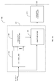
Fig. 1a is a block diagram of an exemplary system for filtering a resonant frequency occurring in a structure having resonant properties; -
Fig. 1b is a schematic diagram of an exemplary system for filtering a resonant frequency occurring in a helicopter rotor; -
Fig. 2 is a schematic side cross-sectional view of an exemplary gas turbine engine; -
Fig. 3a is a block diagram of an exemplary embodiment of the control system ofFigs. 1a and1b ; -
Fig. 3b is a block diagram showing exemplary embodiments for the filtering unit and frequency detection unit offigure 3a ; -
Fig. 3c . is a block diagram of another exemplary embodiment of the filtering unit with an added derivative path; -
Fig. 3d . is a block diagram of an exemplary embodiment of the control system with an added filter size (i.e. width and/or depth) setting unit; -
Fig. 3e . is a block diagram of another exemplary embodiment of the control system with an added out of range detection unit; -
Fig. 3f is a block diagram of another exemplary embodiment of the control system with an added dynamic range centering unit; -
Fig. 4 is a Bode plot of the bank filters; -
Fig. 5 is a flowchart of an exemplary method for dynamically setting an attenuation frequency of an adaptive filter; -
Fig. 6a is a flowchart of an exemplary method of filtering; and -
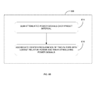
Fig. 6b is a flowchart of an exemplary method of determining a resonating frequency. - There is illustrated in
figure 1 a an exemplary system for detecting a resonant frequency occurring in a structure having resonant properties. Acontrol system 100 is connected to the structure havingresonant properties 200. Thecontrol system 100 dynamically computes a frequency of structural resonance in real-time during normal closed-loop operation and accordingly sets the parameters of an adaptive compensator, such as a filter, a control loop, or other types of compensators, as will be explained in more detail below. Thecontrol system 100 may be used for any structure havingresonant properties 200, such as but not limited to, gimbaled turrets, control of helicopters, stabilization platforms, gyroscopic rate sensors, computer hard drives, and flexible robotic manipulators. - Referring to
Fig. 1b , there is shown an exemplary embodiment for thestructure 200 corresponding to a helicopter rotor-damper system. Arotor shaft 24 may mechanically couple via agearbox 26 to amain rotor 30 and atail rotor 32 of a helicopter. Viscouslag dampers 34 may be coupled betweenblades 36 of themain rotor 30 and arotor hub 38 to increase the damping of the torsional oscillations of themain rotor 30 and of thetail rotor 32, such oscillations illustratively occurring at frequencies in a range of 2 to 8 Hz. Alternatively, thedampers 34 may be positioned between eachblade 36. A rotor drive train illustratively comprises thegearbox 26, themain rotor blades 36, therotor hub 38, and thetail rotor 32. - A
sensor 42 may further be coupled to therotor shaft 24 to provide an output signal representative of engine speed. Thecontrol system 100 may receive the turbine speed or torque measurement along with additional engine parameters and output signals used for controlling the operation of anengine 10. In particular, thecontrol system 100 may be used to modulate a flow of fuel to theengine 10 in order to increase the damping of the torsional oscillations of the rotor drive train. Alternatively to active damping, the natural torsional oscillations of the rotor drive system may be attenuated from the measured signal to prevent thecontrol system 100 from reacting, leading to dynamic instability. As more load is usually present on themain rotor blades 36, torsional oscillations of themain rotor 30 may be dominant, and thus more problematic, and it may therefore be desirable to mainly attenuate the main rotor resonance. Still, although the description below refers to attenuating of the resonance of themain rotor 30, it should be understood that the resonance of thetail rotor 32 may also be attenuated. Thecontrol system 100 may be used to filter out unwanted frequencies elsewhere in an aircraft or in a gas turbine engine, such as natural modes. The aircraft-based control system may also be used for aircrafts other than helicopters (such as fixed wing aircrafts) and other engine types. -
Fig. 2 illustrates anexemplary engine 10, namely a gas turbine engine, comprising aninlet 12, through which ambient air is propelled, acompressor section 14 for pressurizing the air, acombustor 16 in which the compressed air is mixed with fuel and ignited for generating an annular stream of hot combustion gases, and aturbine section 18 for extracting energy from the combustion gases. Theturbine section 18 illustratively comprises acompressor turbine 20, which drives the compressor assembly and accessories, and at least one power orfree turbine 22, which is independent from thecompressor turbine 20 and drives therotor shaft 24 through thereduction gearbox 26. Hot gases may then be evacuated throughexhaust stubs 28. The gas generator 29 of theengine 10 illustratively comprises thecompressor section 14, thecombustor 16, and theturbine section 18. - The
control system 100 may be part of a Full Authority Digital Engine Control (FADEC) used to manage operation of theengine 10 by modulating fuel flow thereto, thereby controlling theengine 10 through acceleration, deceleration, and steady state operation. As such, thecontrol system 100 may comprise a digital computer or Engine Control Unit (ECU, not shown) in communication with the hardware of theengine 10 for controlling an operation of the latter. Thecontrol system 100 may then be implemented as a processor-based system where the term processor may refer to a microprocessor, application specific integrated circuits (ASIC), logic circuits, or any other suitable processor or circuit know to those skilled in the art. - Referring to
Fig. 3a , thecontrol system 100 illustratively comprises an adaptivepre-compensating module 301 comprising afiltering unit 302, afrequency detection unit 304 and an adaptive compensator, which will be referred to as anadaptive filter 306 for the purposes of the present description. The control system also comprises afeedback controller 318. Thefiltering unit 302 comprises a bank of filters spaced along a frequency detection range. A sensed signal needing to be filtered is received by both thefiltering unit 302 and theadaptive filter 306. The sensed signal may be any signal shaping/filtering function in a control system, such as torque, speed, and pressure measurements. Thefiltering unit 302 filters the sensed signal at a plurality of frequencies within the frequency detection range using the bank of filters and outputs a plurality of attenuated power signals. Thefrequency detection unit 304, operatively connected to thefiltering unit 302, receives the attenuated power signals and identifies two filters from the bank of filters with the relatively lowest power. The range between the center frequencies of the two filters is indicative that thestructure 200 has a resonating frequency within this frequency range. Thefrequency detection unit 304 determines the resonating frequency by averaging the center frequencies of the two frequency filters using a weighted average paradigm, where the weights are respectively proportional to the level of attenuation of each filter. The resulting value is used to set the center frequency of theadaptive filter 306 in order to suppress the resonance from the sensed signal. -
Figure 3b illustrates a first exemplary embodiment for thefiltering unit 302 and thefrequency detection unit 304. Thefiltering unit 302 illustratively comprises a band-pass filter 308, a bank offilters 1 to N (collectively referred to as 310), and a corresponding multiplier (collectively referred to as 312) for eachfilter 1 to N. The bank offilters 310 may be filters that pass most frequencies unaltered but attenuate those in a specific range to very low levels, i.e. band-stop filters or band-rejection filters, such as notch filters. Other types of filters, such as combinations of high and low pass filters, may also be used. - The number of
filters 310 may be set as desired to cover a predetermined frequency range. The spacing between the filters may also be set as desired, as a function of the number of filters in the bank offilters 310 and the frequency range to be covered. Accuracy may be a factor in deciding how to space the filters in the bank offilters 310, as accuracy is reduced when spacing is increased, and desired computational speed may impose a limit on the number of filters. For example, six filters may be spaced over a range of 2Hz, with 0.4 Hz between the center frequencies of each filter in thebank 310. Other examples with the same spacing between center frequencies include having twelve filters over a range of 4 Hz and eighteen filters over a range of 6 Hz. Other values for spacing between filters may also be used, such as 0.2 Hz, 0.4Hz, 0.5 Hz, etc. The filters do not need to be evenly spaced but even spacing provides a same degree of frequency detection accuracy across the detection range. If unevenly spaced, it may be desirable to keep the spacing low in order to increase accuracy. Similarly, the filters do not need to overlap, although accuracy may also be affected in such a case. The filters in thebank 310 may be provided with a same width and/or depth, or have some minor variances therebetween. They may be fixed filters or adaptive filters capable of having their center frequency modified post-design. In some embodiments, the center frequencies of the adaptive filters in thebank 310 may be set dynamically such that their overall range is continuously centered around the resonating frequency. This range centering function provides an extended working range for the frequency detection. - The band-
pass filter 308, or any other type of pre-processing, may be used to enhance the sensed signal at a predetermined frequency detection range, as well as zero out the mean of the original signal. The zeroing of the signal mean provides a comparable signal power which is calculated after the band-passed signal is passed through the bank offilters 310. Having the filters in thebank 310 be spaced apart and each falling within the predetermined frequency detection range provides a comparatively distinguishable degree of attenuation from each filter. The output of each filter from thebank 310 is squared by themultipliers 312 in order to obtain the attenuated signal power, which are then passed on to thefrequency detection unit 304. - The
frequency detection unit 304 illustratively comprises a set of accumulators (collectively referred to as 314) and anaggregator 316. Theaccumulators 314 receive the attenuated signal powers from themultipliers 312 and accumulate each sum signal power over a small preset interval, such as six frames of 20ms intervals, for example. At the end of each interval, theaggregator 316 locates the resonating frequency between two adjacent filters from thebank 310 with the lowest relative power. The resonating frequency is then calculated by averaging center frequencies of the two frequency filters using a weighted average paradigm where the weights are respectively proportional to the level of attenuation of each filter. - In some embodiments, the frequency is identified by used the pattern of the frequency on two or more signals, such as the signal and its derivative. A derivative path is added to the
filtering unit 302 in order to reduce small flickers in the detected frequency due to additional noise of other frequencies in the sensed signal. This is illustrated infigure 3c , where the derivative path illustratively comprises aderivative filter 320, a second bank offilters 1 to N (collectively referred to as 322), amultiplier 312 after each filter, and a set of summers (collectively referred to as 324). Thederivative filter 320 receives as input the band-passed signal from band-pass filter 308 and outputs its derivative, which is then passed through the second bank offilters 322. The outputs are squared by themultipliers 312 to obtain the attenuated signal power and these signal powers are summed with the signal powers of the first bank offilters 310 bysummers 324. That is to say, the power fromfilter 1 ofbank 310 is added to the power offilter 1 ofbank 322, the power offilter 2 ofbank 310 is added to the power offilter 2 ofbank 322, and the power of filter N ofbank 310 is added to the power of filter N ofbank 322. The summation of two corresponding attenuated signal powers, one being the derivative of the other, helps enhance the localization of the resonating frequency and may also help improve detection speed. In an alternative example, a lead filter can be used instead of a derivative filter. - In some embodiments, the depth and/or width of
adaptive filter 306 may be set dynamically. This is illustrated infigure 3d , wherein a filtersize setting unit 326 illustratively receives the resonating frequency as calculated from thefrequency detection unit 304, in this case theaggregator 316, and sets at least one of width and depth accordingly. As the resonating frequency may vary slightly after detection, a wider filter will provide theadaptive filter 306 with flexibility to capture the variations. However, it may be desirable to have a deeperadaptive filter 306 to ensure more attenuating of the resonating frequency. A fluctuating signal may require awider filter 306 while a stable signal may allow for adeeper filter 306. The filtersize setting unit 326 may thus be adapted to optimize the depth and width to meet desired criteria with regards to attenuating and post-detection variations. Similarly, the filtersize setting unit 326 may be used to dynamically set the depth and/or width offilters - In some embodiments, the filter
size setting unit 326 is also adapted to take into account lag effects within the feedback control loop of the system. As illustratively shown, theadaptive filter 306 may send the filtered signal to afeedback controller 318, which may be, for example, a proportional-integral-derivative (PID) controller as used in several industrial control systems. Thefeedback controller 318 may be affected if theadaptive filter 306 is too wide or too close to the bandwidth of thefeedback controller 318, thus causing a lag. If the lag is too high, the feedback loop may then be affected. Since the control loop performance is affected by the phase lag inherently introduced by the filter(s), depending on their width and their location (frequency) from the control loop bandwidth, a lag effect may be defined as a function of the filter(s) width/depth. This parameter may then be used by the filtersize setting unit 326 to limit the width/depth variation to maintain a desired control performance. - In some embodiments, it may be desirable to determine if the resonating frequency is beyond the intended detection range. This may be done using an out of
range detection unit 328, as illustrated infigure 3e . The out ofrange detection unit 328 may be used to detect out of range signals and freeze the resonating frequency of theadaptive filter 306 to the last known detected value. Various algorithms may be used to detect out of range signals. - As indicated above, the center frequencies of the filters in the
bank 310 may be set dynamically such that their overall range is continuously centered around the resonating frequency. This range centering function provides an extended working range for the frequency detection. A dynamicrange centering unit 327 is illustrated infigure 3f , and receives as input a signal from band-pass filter 308, the outputs of theaccumulators 314, and the output of theaggregator 316. Its output is then sent to the bank offilters 310/312 and to theaggregator 316. Various algorithms may be used to continuously vary and center the frequency detection range around the detected resonating frequency. One exemplary algorithm can be to keep the spacing ofadaptive filters filters individual filters frequency centering unit 327 may provide a wider range of detectable frequencies while ensuring accuracy. - Referring to
figure 4 , two exemplary algorithms are described. In a first algorithm, the band-pass filtered signal power from band-pass filter 308 is compared to the power from the first filter ofbank 310 and "Range-F" is obtained. The same signal power is compared to the power from the last filter ofbank 310 and "Range-L" is obtained. A condition is set such that if the band-pass filtered signal power is lower than "Range-F" OR "Range-L", then the resonating frequency is out of range. In a second algorithm, the band-pass filtered signal power from band-pass filter 308 is compared to the minimum power from the bank offilters 310, which corresponds to "Range-All". The condition set is such that if the band-pass filtered signal power is lower than "Range-All", then the signal is out of range. Other algorithms to detect out of range signals may also be used. - Referring now to
figure 5 , there is illustrated a method for dynamically setting the attenuation frequency of an adaptive filter, as performed by thecontrol system 100 illustrated infigure 3a . As per the above description, a sensed signal is filtered through a first set of a plurality of frequency filters spaced along afrequency detection range 502 and a plurality of attenuated power signals are output. The two filters having the relatively lowest power are identified 504. The resonating frequency is determined 506 by aggregating the center frequencies of the two filters and their corresponding attenuated power signals, and the center frequency of the adaptive filter is set to theresonating frequency 508. -
Figure 6a illustratively shows an exemplary embodiment for filtering the sensed signal through thefiltering unit 502, as performed by the embodiment of thefiltering unit 302 illustrated infigure 3c . The sensed signal is enhanced and the signal mean is removed therefrom 602. The resulting signal is filtered through a first bank offilters 604 and the output of each filter from the first bank is squared 606 to obtain the attenuated signal power. In parallel, a derivative of the resulting signal is filtered through a second bank offilters 608 and the output of each filter from the second bank is squared 610 to obtain the attenuated signal power. The attenuated signal powers from both banks of filters are summed together 612. -
Figure 6b illustratively shows an exemplary embodiment for determining theresonating frequency 506, as performed by thefrequency detection unit 304 illustrated infigure 3c . The attenuated power signals, as received from thefiltering unit 302, are summed over apreset interval 614. The center frequencies of the two filters with the lowest relative power, as identified instep 504, are aggregated with the attenuated power signals of the same two filters. The resulting value is the resonating frequency of the structure, which will be used to set the center frequency of theadaptive filter 306. - The above description is meant to be exemplary only, and one skilled in the art will recognize that changes may be made to the embodiments described without departing from the scope of the invention disclosed. Modifications which fall within the scope of the present invention will be apparent to those skilled in the art, in light of a review of this disclosure, and such modifications are intended to fall within the appended claims.
Claims (15)
- A control system (100) for dynamically setting a parameter of an adaptive compensator (306) for attenuating a variable frequency from a resonating structure in an aircraft, the system comprising:a filtering unit (302) comprising a first set of a plurality of frequency filters (310) spaced along a frequency detection range for receiving a sensed signal and outputting a plurality of attenuated power signals;a frequency detection unit (304) operatively connected to the filtering unit (302) for receiving the plurality of attenuated power signals, identifying two of the frequency filters (310) having a relatively lowest power, and determining a resonating frequency by averaging center frequencies of the two identified frequency filters (314); andan adaptive compensator (306) operatively connected to the frequency detection unit (304) and having a variable parameter to be set in accordance with the resonating frequency as determined by the frequency detection unit (304).
- The system of claim 1, wherein the filtering unit (302) comprises:a first pre-processing filter (308) operatively connected to an input of the frequency filters (310) for receiving and enhancing a sensed signal, removing a signal mean therefrom, and outputting a pre-processed signal to the frequency filters (310); anda multiplier (312) operatively connected to an output of each one of the frequency filters (310), for squaring a corresponding attenuated signal from each one of the frequency filters (310) and obtaining a corresponding attenuated power signal.
- The system of claim 2, wherein the filtering unit (302) comprises:a derivative filter (320) operatively connected to the first pre-processing filter (308) for receiving the pre-processing signal and outputting a derivative thereof;a second set of the plurality of frequency filters (322), for receiving the derivative output and outputting a plurality of derivative attenuated power signals, the second set of frequency filters (322) also having multipliers (312) operatively connected at an output thereof; anda summer (324) operatively connected between each frequency filter from the first set (310) and a corresponding frequency filter from the second set (322), via the multipliers (312), and the frequency detection unit (304).
- The system of any one of claims 2 to 3, wherein the frequency detection unit (304) comprises:an accumulator (314) operatively connected to an output of each one of the multipliers (312), for summing signal power over a preset interval; andan aggregator (316) operatively connected to the accumulators (314), for averaging the center frequencies of the two identified frequency filters (310).
- The system of any one of claims 1 to 4, further comprising a filter size setting unit (326) operatively connected between the frequency detection unit (304) and the adaptive compensator (306), for dynamically setting at least one of a width and a depth of the adaptive compensator (306) as a function of the resonating frequency, and wherein, optionally, the filter size setting unit (326) is also operatively connected to a feedback controller (318) to receive a signal indicative of a lag time of a feedback loop, and is adapted to limit the width of the adaptive compensator (306) as a function of the lag time.
- The system of any one of claims 1 to 5, further comprising an out of range detection unit (328) operatively connected between the filtering unit (302) and the frequency detection unit (304), for determining if the sensed signal is outside of the frequency detection range and setting the variable parameter of the adaptive compensator (306) in accordance with a last known value within the frequency detection range when the sensed signal is outside of the frequency detection range.
- The system of any one of claims 1 to 6, further comprising a dynamic range centering unit (327) operatively connected between the filtering unit (302) and the frequency detection unit (304), for dynamically setting center frequencies of the plurality of frequency filters (310) such that an overall detection range is centered around the resonating frequency.
- The system of any one of claims 1 to 7, wherein the adaptive compensator (306) comprises an adaptive filter (306) and the variable parameter is a center frequency of the adaptive filter (306), and wherein the filtering unit (302) is adapted to receive the sensed signal from a helicopter rotor system, and/or wherein the frequency filters (310) are overlapping and have evenly spaced center frequencies.
- A method for dynamically setting a variable parameter of an adaptive compensator (306) for attenuating a variable frequency from a resonating structure (200) in an aircraft, the method comprising:filtering a sensed signal through a first set of a plurality of frequency filters (310) spaced along a frequency detection range and outputting a plurality of attenuated power signals;identifying two of the frequency filters (310) having a relatively lowest power;determining a resonating frequency by averaging center frequencies of the two identified frequency filters (310); andsetting the variable parameter of the adaptive compensator in accordance with the resonating frequency.
- The method of claim 9, wherein filtering the sensed signal comprises:enhancing the sensed signal and removing a signal mean therefrom before filtering through the plurality of frequency filters (310); andsquaring an output of each one of the frequency filters (310) to obtain the attenuated power signals;and optionally:summing squared outputs from the first set of frequency filters (310) with squared outputs from the second set of frequency filters (322).filtering a derivative of the sensed signal through a second set of the plurality of frequency filters (322); andsquaring an output of each one of the frequency filters from the second set (322); and
- The method of any one of claims 9 to 10, wherein determining the resonating frequency comprises summing the attenuated power signals over a preset interval before averaging the center frequencies of the two identified frequency filters (310).
- The method of any one of claims 9 to 11, further comprising dynamically setting at least one of a width and a depth of the adaptive compensator (306) as a function of the resonating frequency, and, optionally, limiting the width of the adaptive compensator (306) as a function of one of a lag time and a phase lag effect of a feedback loop.
- The method of any one of claims 9 to 12, further comprising determining if the sensed signal is outside of the frequency detection range and setting the variable parameter of the adaptive compensator (306) in accordance with a last known value within the frequency detection range when the sensed signal is outside of the frequency detection range.
- The method of any one of claims 9 to 13, further comprising dynamically setting center frequencies of the plurality of frequency filters (310) such that an overall detection range is centered around the resonating frequency.
- The method of any one of claims 9 to 14, wherein the adaptive compensator (306) comprises an adaptive filter (306) and the variable parameter is a center frequency of the adaptive filter (306), and wherein filtering the sensed signal comprises receiving the sensed signal from a helicopter rotor system.
Applications Claiming Priority (1)
| Application Number | Priority Date | Filing Date | Title |
|---|---|---|---|
| US13/888,032 US9099980B2 (en) | 2013-05-06 | 2013-05-06 | Dynamically detecting resonating frequencies of resonating structures |
Publications (3)
| Publication Number | Publication Date |
|---|---|
| EP2801878A2 true EP2801878A2 (en) | 2014-11-12 |
| EP2801878A3 EP2801878A3 (en) | 2016-06-29 |
| EP2801878B1 EP2801878B1 (en) | 2020-03-11 |
Family
ID=50841563
Family Applications (1)
| Application Number | Title | Priority Date | Filing Date |
|---|---|---|---|
| EP14166555.4A Active EP2801878B1 (en) | 2013-05-06 | 2014-04-30 | Dynamically detecting resonating frequencies of resonating structures |
Country Status (3)
| Country | Link |
|---|---|
| US (2) | US9099980B2 (en) |
| EP (1) | EP2801878B1 (en) |
| CA (1) | CA2850888C (en) |
Cited By (1)
| Publication number | Priority date | Publication date | Assignee | Title |
|---|---|---|---|---|
| DE102022129477A1 (en) | 2022-11-08 | 2024-05-08 | Audi Aktiengesellschaft | Control device and method for controlling an engine of a drive train of a motor vehicle and correspondingly designed motor vehicle |
Families Citing this family (8)
| Publication number | Priority date | Publication date | Assignee | Title |
|---|---|---|---|---|
| US9002615B2 (en) * | 2012-01-18 | 2015-04-07 | General Electric Company | Methods and systems for managing power of an engine |
| US9261026B2 (en) * | 2013-06-27 | 2016-02-16 | Pratt & Whitney Canada Corp. | System and method for conditioning noisy signals |
| US9852744B2 (en) * | 2014-12-16 | 2017-12-26 | Psyx Research, Inc. | System and method for dynamic recovery of audio data |
| FR3067325B1 (en) * | 2017-06-13 | 2022-02-18 | Airbus Helicopters | REGULATION SYSTEM FOR CONTROLLING THE VIBRATIONAL BEHAVIOR AND/OR THE TORSIONAL STABILITY OF A KINEMATIC CHAIN, GIRAVION EQUIPPED WITH SUCH A REGULATION SYSTEM AND ASSOCIATED REGULATION METHOD |
| FR3076361B1 (en) * | 2018-01-04 | 2019-12-13 | Safran Aircraft Engines | ADAPTIVE FILTERING PROCESS |
| CN110949689B (en) * | 2019-12-06 | 2022-07-22 | 江西洪都航空工业集团有限责任公司 | Method for measuring full-motion horizontal tail rotation mode of airplane |
| CN115235444B (en) * | 2022-07-19 | 2023-02-24 | 青岛哈尔滨工程大学创新发展中心 | Method for measuring control loop bandwidth of full-angle hemispherical resonator gyroscope |
| CN117600050B (en) * | 2023-12-21 | 2026-04-21 | 湖南三一智能控制设备有限公司 | Method, device and leveling system for adaptive adjustment of center frequency of ultrasonic transducer |
Family Cites Families (13)
| Publication number | Priority date | Publication date | Assignee | Title |
|---|---|---|---|---|
| US4430744A (en) * | 1981-12-18 | 1984-02-07 | Gte Automatic Electric Incorporated | Adaptive IF equalizer for digital transmission |
| US5189620A (en) | 1989-10-06 | 1993-02-23 | United Technologies Corporation | Control system for gas turbine helicopter engines and the like |
| EP0693212B1 (en) * | 1993-04-07 | 1999-12-08 | Noise Cancellation Technologies, Inc. | Hybrid analog/digital vibration control system |
| US5717772A (en) * | 1995-08-07 | 1998-02-10 | Motorola, Inc. | Method and apparatus for suppressing acoustic feedback in an audio system |
| US5710720A (en) * | 1996-04-30 | 1998-01-20 | Board Of Regents Of The University Of Nebraska | Phase lock loop based system and method for decomposing and tracking decomposed frequency components of a signal, with application to vibration compensation system |
| US6487295B1 (en) * | 1998-09-25 | 2002-11-26 | Ortivus Ab | Adaptive filtering system and method |
| AU2002244175A1 (en) * | 2001-02-27 | 2002-09-12 | Sikorsky Aircraft Corporation | System for computationally efficient active control of tonal sound or vibration |
| FR2834563B1 (en) * | 2002-01-08 | 2004-04-02 | Thales Sa | METHOD FOR SUPPRESSING PULSE RADIO-ELECTRIC SIGNALS AND DEVICE FOR IMPLEMENTING THE METHOD |
| US6867642B1 (en) | 2003-08-25 | 2005-03-15 | Lockheed Martin Corporation | Realtime adaptive notch compensator |
| JP4324736B2 (en) | 2004-05-17 | 2009-09-02 | 株式会社島津製作所 | Magnetic bearing control device |
| US7839304B2 (en) * | 2008-05-01 | 2010-11-23 | The United States Of America As Represented By The Secretary Of The Navy | Method and system for alerting aircrew to unsafe vibration levels |
| GB201004469D0 (en) | 2010-03-18 | 2010-05-05 | Rolls Royce Plc | Controlling blade pitch angle |
| US8829701B2 (en) * | 2012-10-11 | 2014-09-09 | Pratt & Whitney Canada Corp. | Resonant mode damping system and method |
-
2013
- 2013-05-06 US US13/888,032 patent/US9099980B2/en active Active
-
2014
- 2014-04-28 CA CA2850888A patent/CA2850888C/en active Active
- 2014-04-30 EP EP14166555.4A patent/EP2801878B1/en active Active
-
2015
- 2015-05-26 US US14/721,751 patent/US9906201B2/en active Active
Non-Patent Citations (1)
| Title |
|---|
| None |
Cited By (1)
| Publication number | Priority date | Publication date | Assignee | Title |
|---|---|---|---|---|
| DE102022129477A1 (en) | 2022-11-08 | 2024-05-08 | Audi Aktiengesellschaft | Control device and method for controlling an engine of a drive train of a motor vehicle and correspondingly designed motor vehicle |
Also Published As
| Publication number | Publication date |
|---|---|
| EP2801878A3 (en) | 2016-06-29 |
| US20150333721A1 (en) | 2015-11-19 |
| CA2850888A1 (en) | 2014-11-06 |
| EP2801878B1 (en) | 2020-03-11 |
| CA2850888C (en) | 2021-02-09 |
| US9906201B2 (en) | 2018-02-27 |
| US20140327489A1 (en) | 2014-11-06 |
| US9099980B2 (en) | 2015-08-04 |
Similar Documents
| Publication | Publication Date | Title |
|---|---|---|
| CA2850888C (en) | Dynamically detecting resonating frequencies of resonating structures | |
| CN102282450B (en) | Method and system for monitoring vibration phenomena generated during operation of a gas turbine engine | |
| CA2812253C (en) | Resonant mode damping system and method | |
| EP3626628B1 (en) | System and method for synchrophasing aircraft engines | |
| US9382847B2 (en) | Rotor resonance disturbance rejection controller | |
| EP2221699A2 (en) | Continuous performance analysis system and method | |
| US9068512B2 (en) | Method for protecting a gas turbine engine against high dynamical process values and gas turbine engine for conducting the method | |
| JP2003148171A (en) | Engine control system | |
| CN112746875B (en) | Active control system and method for complex vibration of rotor shaft system of aircraft engine | |
| US20220170819A1 (en) | Method and system for monitoring a status of a reducer of a gas turbine | |
| US20180278188A1 (en) | Torsional damping for generators | |
| KR102515403B1 (en) | Blade pitch controller for wind turbines | |
| EP3401527A1 (en) | Turbocharger surging detection method and surging detection device | |
| CN115949550B (en) | Wave pitching motion control method and system for offshore floating wind turbine generator | |
| CN108688648A (en) | The control device and hybrid vehicle of hybrid vehicle | |
| CN110794681A (en) | A FxLMS Filtering Method for Narrowband Active Vibration Systems | |
| CN112539136B (en) | A torsional vibration suppression control method for coping with persistent turbulent excitation | |
| KR20180052711A (en) | Method for controlling power system and generator voltage | |
| US7848854B2 (en) | Prime mover output control system | |
| RU2351807C2 (en) | Method of protecting gas turbine engine against surge | |
| CN112881025B (en) | Method for vibration control and energy collection of aircraft engine | |
| EP3931085B1 (en) | Active vibration control system in a gunfire vibration environment | |
| CN113726236A (en) | Wind generating set and control system thereof | |
| US10730613B2 (en) | Regulation system for controlling the vibratory behavior and/or the twisting stability of a drivetrain, a rotorcraft fitted with such a regulation system, and an associated regulation method | |
| CN121184844A (en) | Control methods, devices and electronic equipment for range hoods |
Legal Events
| Date | Code | Title | Description |
|---|---|---|---|
| PUAI | Public reference made under article 153(3) epc to a published international application that has entered the european phase |
Free format text: ORIGINAL CODE: 0009012 |
|
| 17P | Request for examination filed |
Effective date: 20140430 |
|
| AK | Designated contracting states |
Kind code of ref document: A2 Designated state(s): AL AT BE BG CH CY CZ DE DK EE ES FI FR GB GR HR HU IE IS IT LI LT LU LV MC MK MT NL NO PL PT RO RS SE SI SK SM TR |
|
| AX | Request for extension of the european patent |
Extension state: BA ME |
|
| PUAL | Search report despatched |
Free format text: ORIGINAL CODE: 0009013 |
|
| AK | Designated contracting states |
Kind code of ref document: A3 Designated state(s): AL AT BE BG CH CY CZ DE DK EE ES FI FR GB GR HR HU IE IS IT LI LT LU LV MC MK MT NL NO PL PT RO RS SE SI SK SM TR |
|
| AX | Request for extension of the european patent |
Extension state: BA ME |
|
| RIC1 | Information provided on ipc code assigned before grant |
Ipc: H03H 7/01 20060101ALI20160523BHEP Ipc: G05B 21/02 20060101AFI20160523BHEP |
|
| R17P | Request for examination filed (corrected) |
Effective date: 20160919 |
|
| RBV | Designated contracting states (corrected) |
Designated state(s): AL AT BE BG CH CY CZ DE DK EE ES FI FR GB GR HR HU IE IS IT LI LT LU LV MC MK MT NL NO PL PT RO RS SE SI SK SM TR |
|
| REG | Reference to a national code |
Ref country code: DE Ref legal event code: R079 Ref document number: 602014062073 Country of ref document: DE Free format text: PREVIOUS MAIN CLASS: G05B0021020000 Ipc: B64C0027000000 |
|
| RIC1 | Information provided on ipc code assigned before grant |
Ipc: B64C 27/00 20060101AFI20190628BHEP |
|
| GRAP | Despatch of communication of intention to grant a patent |
Free format text: ORIGINAL CODE: EPIDOSNIGR1 |
|
| STAA | Information on the status of an ep patent application or granted ep patent |
Free format text: STATUS: GRANT OF PATENT IS INTENDED |
|
| INTG | Intention to grant announced |
Effective date: 20190918 |
|
| GRAS | Grant fee paid |
Free format text: ORIGINAL CODE: EPIDOSNIGR3 |
|
| GRAA | (expected) grant |
Free format text: ORIGINAL CODE: 0009210 |
|
| STAA | Information on the status of an ep patent application or granted ep patent |
Free format text: STATUS: THE PATENT HAS BEEN GRANTED |
|
| AK | Designated contracting states |
Kind code of ref document: B1 Designated state(s): AL AT BE BG CH CY CZ DE DK EE ES FI FR GB GR HR HU IE IS IT LI LT LU LV MC MK MT NL NO PL PT RO RS SE SI SK SM TR |
|
| REG | Reference to a national code |
Ref country code: GB Ref legal event code: FG4D |
|
| REG | Reference to a national code |
Ref country code: CH Ref legal event code: EP |
|
| REG | Reference to a national code |
Ref country code: AT Ref legal event code: REF Ref document number: 1242856 Country of ref document: AT Kind code of ref document: T Effective date: 20200315 |
|
| REG | Reference to a national code |
Ref country code: IE Ref legal event code: FG4D |
|
| REG | Reference to a national code |
Ref country code: DE Ref legal event code: R096 Ref document number: 602014062073 Country of ref document: DE |
|
| PG25 | Lapsed in a contracting state [announced via postgrant information from national office to epo] |
Ref country code: NO Free format text: LAPSE BECAUSE OF FAILURE TO SUBMIT A TRANSLATION OF THE DESCRIPTION OR TO PAY THE FEE WITHIN THE PRESCRIBED TIME-LIMIT Effective date: 20200611 Ref country code: RS Free format text: LAPSE BECAUSE OF FAILURE TO SUBMIT A TRANSLATION OF THE DESCRIPTION OR TO PAY THE FEE WITHIN THE PRESCRIBED TIME-LIMIT Effective date: 20200311 Ref country code: FI Free format text: LAPSE BECAUSE OF FAILURE TO SUBMIT A TRANSLATION OF THE DESCRIPTION OR TO PAY THE FEE WITHIN THE PRESCRIBED TIME-LIMIT Effective date: 20200311 |
|
| REG | Reference to a national code |
Ref country code: NL Ref legal event code: MP Effective date: 20200311 |
|
| PG25 | Lapsed in a contracting state [announced via postgrant information from national office to epo] |
Ref country code: GR Free format text: LAPSE BECAUSE OF FAILURE TO SUBMIT A TRANSLATION OF THE DESCRIPTION OR TO PAY THE FEE WITHIN THE PRESCRIBED TIME-LIMIT Effective date: 20200612 Ref country code: LV Free format text: LAPSE BECAUSE OF FAILURE TO SUBMIT A TRANSLATION OF THE DESCRIPTION OR TO PAY THE FEE WITHIN THE PRESCRIBED TIME-LIMIT Effective date: 20200311 Ref country code: SE Free format text: LAPSE BECAUSE OF FAILURE TO SUBMIT A TRANSLATION OF THE DESCRIPTION OR TO PAY THE FEE WITHIN THE PRESCRIBED TIME-LIMIT Effective date: 20200311 Ref country code: HR Free format text: LAPSE BECAUSE OF FAILURE TO SUBMIT A TRANSLATION OF THE DESCRIPTION OR TO PAY THE FEE WITHIN THE PRESCRIBED TIME-LIMIT Effective date: 20200311 Ref country code: BG Free format text: LAPSE BECAUSE OF FAILURE TO SUBMIT A TRANSLATION OF THE DESCRIPTION OR TO PAY THE FEE WITHIN THE PRESCRIBED TIME-LIMIT Effective date: 20200611 |
|
| REG | Reference to a national code |
Ref country code: LT Ref legal event code: MG4D |
|
| PG25 | Lapsed in a contracting state [announced via postgrant information from national office to epo] |
Ref country code: NL Free format text: LAPSE BECAUSE OF FAILURE TO SUBMIT A TRANSLATION OF THE DESCRIPTION OR TO PAY THE FEE WITHIN THE PRESCRIBED TIME-LIMIT Effective date: 20200311 |
|
| PG25 | Lapsed in a contracting state [announced via postgrant information from national office to epo] |
Ref country code: CZ Free format text: LAPSE BECAUSE OF FAILURE TO SUBMIT A TRANSLATION OF THE DESCRIPTION OR TO PAY THE FEE WITHIN THE PRESCRIBED TIME-LIMIT Effective date: 20200311 Ref country code: RO Free format text: LAPSE BECAUSE OF FAILURE TO SUBMIT A TRANSLATION OF THE DESCRIPTION OR TO PAY THE FEE WITHIN THE PRESCRIBED TIME-LIMIT Effective date: 20200311 Ref country code: LT Free format text: LAPSE BECAUSE OF FAILURE TO SUBMIT A TRANSLATION OF THE DESCRIPTION OR TO PAY THE FEE WITHIN THE PRESCRIBED TIME-LIMIT Effective date: 20200311 Ref country code: IS Free format text: LAPSE BECAUSE OF FAILURE TO SUBMIT A TRANSLATION OF THE DESCRIPTION OR TO PAY THE FEE WITHIN THE PRESCRIBED TIME-LIMIT Effective date: 20200711 Ref country code: SK Free format text: LAPSE BECAUSE OF FAILURE TO SUBMIT A TRANSLATION OF THE DESCRIPTION OR TO PAY THE FEE WITHIN THE PRESCRIBED TIME-LIMIT Effective date: 20200311 Ref country code: PT Free format text: LAPSE BECAUSE OF FAILURE TO SUBMIT A TRANSLATION OF THE DESCRIPTION OR TO PAY THE FEE WITHIN THE PRESCRIBED TIME-LIMIT Effective date: 20200805 Ref country code: SM Free format text: LAPSE BECAUSE OF FAILURE TO SUBMIT A TRANSLATION OF THE DESCRIPTION OR TO PAY THE FEE WITHIN THE PRESCRIBED TIME-LIMIT Effective date: 20200311 Ref country code: EE Free format text: LAPSE BECAUSE OF FAILURE TO SUBMIT A TRANSLATION OF THE DESCRIPTION OR TO PAY THE FEE WITHIN THE PRESCRIBED TIME-LIMIT Effective date: 20200311 |
|
| REG | Reference to a national code |
Ref country code: AT Ref legal event code: MK05 Ref document number: 1242856 Country of ref document: AT Kind code of ref document: T Effective date: 20200311 |
|
| REG | Reference to a national code |
Ref country code: CH Ref legal event code: PL |
|
| REG | Reference to a national code |
Ref country code: DE Ref legal event code: R097 Ref document number: 602014062073 Country of ref document: DE |
|
| PG25 | Lapsed in a contracting state [announced via postgrant information from national office to epo] |
Ref country code: MC Free format text: LAPSE BECAUSE OF FAILURE TO SUBMIT A TRANSLATION OF THE DESCRIPTION OR TO PAY THE FEE WITHIN THE PRESCRIBED TIME-LIMIT Effective date: 20200311 |
|
| PLBE | No opposition filed within time limit |
Free format text: ORIGINAL CODE: 0009261 |
|
| STAA | Information on the status of an ep patent application or granted ep patent |
Free format text: STATUS: NO OPPOSITION FILED WITHIN TIME LIMIT |
|
| PG25 | Lapsed in a contracting state [announced via postgrant information from national office to epo] |
Ref country code: ES Free format text: LAPSE BECAUSE OF FAILURE TO SUBMIT A TRANSLATION OF THE DESCRIPTION OR TO PAY THE FEE WITHIN THE PRESCRIBED TIME-LIMIT Effective date: 20200311 Ref country code: LI Free format text: LAPSE BECAUSE OF NON-PAYMENT OF DUE FEES Effective date: 20200430 Ref country code: DK Free format text: LAPSE BECAUSE OF FAILURE TO SUBMIT A TRANSLATION OF THE DESCRIPTION OR TO PAY THE FEE WITHIN THE PRESCRIBED TIME-LIMIT Effective date: 20200311 Ref country code: AT Free format text: LAPSE BECAUSE OF FAILURE TO SUBMIT A TRANSLATION OF THE DESCRIPTION OR TO PAY THE FEE WITHIN THE PRESCRIBED TIME-LIMIT Effective date: 20200311 Ref country code: CH Free format text: LAPSE BECAUSE OF NON-PAYMENT OF DUE FEES Effective date: 20200430 Ref country code: LU Free format text: LAPSE BECAUSE OF NON-PAYMENT OF DUE FEES Effective date: 20200430 Ref country code: IT Free format text: LAPSE BECAUSE OF FAILURE TO SUBMIT A TRANSLATION OF THE DESCRIPTION OR TO PAY THE FEE WITHIN THE PRESCRIBED TIME-LIMIT Effective date: 20200311 |
|
| REG | Reference to a national code |
Ref country code: BE Ref legal event code: MM Effective date: 20200430 |
|
| 26N | No opposition filed |
Effective date: 20201214 |
|
| PG25 | Lapsed in a contracting state [announced via postgrant information from national office to epo] |
Ref country code: BE Free format text: LAPSE BECAUSE OF NON-PAYMENT OF DUE FEES Effective date: 20200430 Ref country code: PL Free format text: LAPSE BECAUSE OF FAILURE TO SUBMIT A TRANSLATION OF THE DESCRIPTION OR TO PAY THE FEE WITHIN THE PRESCRIBED TIME-LIMIT Effective date: 20200311 Ref country code: SI Free format text: LAPSE BECAUSE OF FAILURE TO SUBMIT A TRANSLATION OF THE DESCRIPTION OR TO PAY THE FEE WITHIN THE PRESCRIBED TIME-LIMIT Effective date: 20200311 |
|
| PG25 | Lapsed in a contracting state [announced via postgrant information from national office to epo] |
Ref country code: IE Free format text: LAPSE BECAUSE OF NON-PAYMENT OF DUE FEES Effective date: 20200430 |
|
| PG25 | Lapsed in a contracting state [announced via postgrant information from national office to epo] |
Ref country code: TR Free format text: LAPSE BECAUSE OF FAILURE TO SUBMIT A TRANSLATION OF THE DESCRIPTION OR TO PAY THE FEE WITHIN THE PRESCRIBED TIME-LIMIT Effective date: 20200311 Ref country code: MT Free format text: LAPSE BECAUSE OF FAILURE TO SUBMIT A TRANSLATION OF THE DESCRIPTION OR TO PAY THE FEE WITHIN THE PRESCRIBED TIME-LIMIT Effective date: 20200311 Ref country code: CY Free format text: LAPSE BECAUSE OF FAILURE TO SUBMIT A TRANSLATION OF THE DESCRIPTION OR TO PAY THE FEE WITHIN THE PRESCRIBED TIME-LIMIT Effective date: 20200311 |
|
| PG25 | Lapsed in a contracting state [announced via postgrant information from national office to epo] |
Ref country code: MK Free format text: LAPSE BECAUSE OF FAILURE TO SUBMIT A TRANSLATION OF THE DESCRIPTION OR TO PAY THE FEE WITHIN THE PRESCRIBED TIME-LIMIT Effective date: 20200311 Ref country code: AL Free format text: LAPSE BECAUSE OF FAILURE TO SUBMIT A TRANSLATION OF THE DESCRIPTION OR TO PAY THE FEE WITHIN THE PRESCRIBED TIME-LIMIT Effective date: 20200311 |
|
| P01 | Opt-out of the competence of the unified patent court (upc) registered |
Effective date: 20230530 |
|
| PGFP | Annual fee paid to national office [announced via postgrant information from national office to epo] |
Ref country code: DE Payment date: 20250319 Year of fee payment: 12 |
|
| PGFP | Annual fee paid to national office [announced via postgrant information from national office to epo] |
Ref country code: GB Payment date: 20260319 Year of fee payment: 13 |
|
| PGFP | Annual fee paid to national office [announced via postgrant information from national office to epo] |
Ref country code: FR Payment date: 20260320 Year of fee payment: 13 |