EP2801328A1 - Intervertebral device - Google Patents
Intervertebral device Download PDFInfo
- Publication number
- EP2801328A1 EP2801328A1 EP13305591.3A EP13305591A EP2801328A1 EP 2801328 A1 EP2801328 A1 EP 2801328A1 EP 13305591 A EP13305591 A EP 13305591A EP 2801328 A1 EP2801328 A1 EP 2801328A1
- Authority
- EP
- European Patent Office
- Prior art keywords
- intervertebral device
- porous layer
- groove
- spacer
- spinous processes
- Prior art date
- Legal status (The legal status is an assumption and is not a legal conclusion. Google has not performed a legal analysis and makes no representation as to the accuracy of the status listed.)
- Withdrawn
Links
Images

Classifications
-
- A—HUMAN NECESSITIES
- A61—MEDICAL OR VETERINARY SCIENCE; HYGIENE
- A61B—DIAGNOSIS; SURGERY; IDENTIFICATION
- A61B17/00—Surgical instruments, devices or methods, e.g. tourniquets
- A61B17/56—Surgical instruments or methods for treatment of bones or joints; Devices specially adapted therefor
- A61B17/58—Surgical instruments or methods for treatment of bones or joints; Devices specially adapted therefor for osteosynthesis, e.g. bone plates, screws, setting implements or the like
- A61B17/68—Internal fixation devices, including fasteners and spinal fixators, even if a part thereof projects from the skin
- A61B17/70—Spinal positioners or stabilisers ; Bone stabilisers comprising fluid filler in an implant
- A61B17/7062—Devices acting on, attached to, or simulating the effect of, vertebral processes, vertebral facets or ribs ; Tools for such devices
Definitions
- the present disclosure relates to an intervertebral device to be placed between two spinous processes of two adjacent vertebrae.
- a device is sometimes called an "interspinous device” or an “interspinous implant”. It is used for holding two vertebrae in a desired relative position.
- the spine is formed of superposed vertebrae, from the lumbar vertebrae to the cervical vertebrae, each having an anterior part, which is the vertebral body, and a posterior part, which is the vertebral arch (or neural arch), the anterior and posterior parts enclosing the vertebral foramen.
- Each vertebral arch is formed by a pair of pedicles and a pair of laminae, and has transverse processes and/or a spinous process (or neural spine) projecting therefrom. The transverse and spinous processes project opposite to the vertebral foramen.
- An intervertebral disc lies between each pair of adjacent vertebrae, i.e. between the vertebral bodies of these vertebrae. Each disc forms a cartilaginous joint to hold the two adjacent vertebrae together while allowing relative movements between these vertebrae.
- an intervertebral disk is damaged (e.g. worn out or degenerated), it becomes unable to prevent excessive relative movements between the two vertebrae contiguous to the disk, during flexion (forward movement) or extension (backward movement) of the spine.
- An abnormal excessive relative movement between two adjacent vertebrae may cause discomfort and/or pain to the patient.
- an intervertebral device between the spinous processes of the two adjacent vertebrae.
- Such a device limits the extent to which the posterior parts of the two vertebrae can move with respect to each other when the spine is extended and/or flexed.
- the device provides stabilization between the vertebrae. This stabilization may be more or less “dynamic” depending on the amount of relative movement allowed between the vertebrae. The less the amount of relative movement allowed, the less dynamic or the more "static" the stabilization.
- intervertebral devices are disclosed, for instance, in US patents No. 7087083 , 7163558 and 7520887 . Those devices provide dynamic stabilization.
- fusion is known in which vertebrae are fixedly connected to each other. It is known, for example, to use so-called cages which are inserted between the vertebrae, as disclosed in European patent No. 1299054 . Such surgery is much more invasive that an interspinous surgery, as commonly e.g. the disc needs to be removed and the surgeon needs to work around the spinal nerves. It is moreover known to affect fusion by means of rigid posterior rod systems which are attached to either pedicles or laminae of the vertebrae by means of hooks or screws. Such systems require access to further structures of the vertebrae themselves, compared to access to the spinous processes only. Such systems are known for example from European patent No. 348272 .
- an intervertebral device to be placed between two spinous processes of two vertebrae.
- the intervertebral device comprises a spacer having two opposite or opposing grooves, each groove being configured to engage a spinous process, wherein at least one porous layer is provided on an inner face of each groove, this porous layer being adapted to interface with the spinous process by allowing bone growth in the porous layer.
- Such a device allows, besides other advantages, rigid or largely rigid connection between two vertebrae by a surgery which is as little invasive as dynamic stabilization by means of an interspinous spacer.
- Such a material may be formed from a reticulated vitreous carbon foam substrate which is infiltrated and coated with a biocompatible metal, such as tantalum, etc., by a chemical vapor deposition ("CVD") process in the manner disclosed in detail in U.S. Patent No. 5282861, issued February 1, 1994 , entitled “open cell tantalum structures for cancellous bone implants and cell and tissue receptors", the entirety of which is included herein by reference, and in Levine, B.R., et al., “Experimental and Clinical Performance of Porous Tantalum in Orthopedic Surgery", Biomaterials 27 (2006) 4671-4681 . Further methods of producing porous metal structures, such as Trabecular MetalTM structures, are provided in WO 2012/065729 .
- tantalum In addition to tantalum, other metals such as niobium or alloys of tantalum and niobium with one another or with other metals may also be used. Bone-ingrowth materials other than Trabecular MetalTM may also be used. For instance, Trabecular TitaniumTM available from Lima Corporate may be used.
- the porous layers may be fixed onto the inner faces of the grooves by pressing, friction, swaging, clamping, gluing, interlocking or any other appropriate fixing technique.
- the porous layers may be fitted into recesses of complementary shape provided in the spacer.
- the two spinous processes are directly bound to the porous layers which are fixed to the spacer. Accordingly, the spinous processes are held together via the spacer.
- the spacer and, more particularly, the central part of it may be slightly deformable in some instances.
- the central part When the central part is slightly deformable, it may allow a limited amount of relative movement between the vertebrae. In other instances, the spacer may generally not be deformable, i.e., rigid.
- the intervertebral device provides static stabilization. Such a device providing static stabilization may provide a desired effect for spinal fusion surgery.
- Spinal fusion is a surgical technique used to permanently join adjacent vertebrae by creating a motionless junction between the vertebrae (i.e. the vertebrae are immobilized with respect to each other).
- the spacer may be made of any desired material, such as polymer and/or metallic materials.
- the spacer may be formed of polyetheretherketone (PEEK) or titanium alloy.
- the intervertebral device may include one or more securement features configured to engage the spinous processes in order to secure the intervertebral device to the spinous processes prior to establishing bone ingrowth into the pores of the porous layer.
- the intervertebral device comprises at least one elongated member adapted to surround the spinous processes for maintaining the spinous processes engaged into the grooves.
- the elongated member allows the spinous processes to be held in position with respect to the spacer and the porous layers, which fosters bone growth in the porous layer.
- the intervertebral device may include pins, spikes, or other fasteners to initially secure the intervertebral device to the spinous processes.
- passing the elongated member(s) around the spinous processes is less invasive than passing pins or spikes through the spinous processes.
- the elongated member may be a tie having a band shape, a cord shape or other shapes. For example, it may be made by weaving or as a cable. It may be made from a polymeric material such as, for example, polyester, polyethylene (for example, polyethylene terephthalate, i.e. PET), polyetheretherketone (PEEK).
- a polymeric material such as, for example, polyester, polyethylene (for example, polyethylene terephthalate, i.e. PET), polyetheretherketone (PEEK).
- a single elongated member may be passed around the two spinous processes or one elongated member may be passed around each spinous process.
- the elongated member or members may form a loop around each spinous process, this loop being tightened against the spinous process, for instance by pulling on the end(s) of the elongated member.
- the elongated member may be fastened to the spacer by any appropriate fastening technique and/or system, such as knotting, sewing, a self-locking system, a clip-fixing system, a clamping system, or a combination thereof.
- each groove is defined between two branches and a porous layer is provided at least on the inner face of the distal part of each branch.
- a porous layer may be provided at a base or bottom of each groove.
- the porous layer may comprise or be made from a material consisting of a web of interconnected rods.
- the rods may leave interconnected voids between them.
- the rods may have a metallic surface and/or be made from a metal or alloy.
- the metallic surface may be made from tantalum, niobium, titanium or an alloy of any two or more thereof.
- the rods may consist of metal coated pyrolized polymeric material.
- the porous layer may have a highly open porosity that imitates the morphology of cancellous bone.
- the above-mentioned rods may form a three dimensional structure, said structure being, in particular, a trabecular structure as found in cancellous bone.
- each groove is defined between two branches extending from a central part of the spacer and at least one branch is deformable toward the other branch.
- the two branches may be deformable toward each other.
- the branches may be deformed toward each other to clamp the spinous process between them.
- at least a portion of each branch, in particular the distal part of the branch i.e., the end of the branch furthest from the central part of the spacer
- tensioning the elongated member(s) may draw the distal parts of the branches toward one another and bring the porous layer into contact with the spinous processes.
- a porous layer is provided on the inner face of the distal parts, the contact between the porous layers and the spinous process is thus improved.
- the elongated member passes along an outer face of each branch.
- the branches are deformable, they may thus be deformed and brought into closer contact with the spinous process by tightening the elongated member around the branches and the spinous process.
- an insert extends within the spacer, between the two opposite grooves, the insert having two opposite ends, each end defining a porous layer at the bottom of each groove. Accordingly, bone growths from the two spinous processes take place in the same insert, thus creating a rigid bone fusion between the adjacent spinous processes.
- a method for stabilizing at least two adjacent vertebrae comprising the steps of providing an intervertebral device according to the present disclosure and impeding relative movement between the vertebrae by placing the intervertebral device between two spinous processes of the vertebrae.
- Such a method is used, in particular, in spinal fusion surgery.
- This method has the advantages derived from using an intervertebral device according to the present disclosure.
- FIG. 1 The appended drawings show examples of intervertebral devices 1. Those devices are adapted to be placed between two adjacent spinous processes SP1, SP2 of two vertebrae, as illustrated in FIG 3 .
- the intervertebral device 1 comprises a spacer 10 having two opposite grooves 14A, 14B adapted to receive the two spinous processes SP1, SP2, respectively, therein and engage the two spinous processes SP1, SP2, respectively.
- Each groove 14A (14B) is defined between two legs or branches 16A, 18A (16B, 18B).
- the branches 16A, 18A (16B, 18B) may be high enough (see their height H1 in FIG 3 ) to cover more than one-half (1/2) of the height H2 of the spinous process SP1 (SP2) concerned, in particular, more than two-thirds (2/3) of the height H2 and, especially, about or more than three-quarters (3/4) of the height H2, the heights H1 and H2 being measured along the central axis of the groove.
- the legs or branches 16A, 18A (16B, 18B) may have a length sufficient to extend along 50% or more, 66% or more, or 75% or more of the height H2 of the spinous process SP1 (SP2), in some instances. Since heights H2 of the spinous processes may vary from one patient to another, kits of several intervertebral devices 1 with various groove heights H1 and/or branch lengths may be provided.
- the device 1 is quasi-symmetrical with respect to a center point 0 (see FIG 1 ) located in the middle of the central part 12 of the spacer 10.
- the spacer 10 comprises two quasi-symmetrical halves 10A, 10B and parts or elements of these two halves having identical or analogous functions, are identified by the same reference number followed by "A" for one part and "B" for the other part.
- the device 1 need not be symmetrical, and in such instances parts or elements of the device 1 associated with, interacting with, or directed toward the first spinous process SP1 may be identified with a reference number followed by "A" while similar parts or elements of the device 1 associated with, interacting with, or directed toward the second spinous process SP2 may be identified with a reference number followed by "B".
- the device 1 may comprise two elongated members (see FIG 2 ), each being formed by a tie 30A, 30B having a band shape, and each tie 30A (30B) having a first, proximal end 32A (32B) and a second, distal end 34A (34B).
- the proximal end 32A (32B) of each tie 30A (30B) may be permanently fastened to the spacer 10.
- the proximal end 32A (32B) may be sewed into a loop, this loop surrounding a part of the spacer 10.
- the distal end 34A (34B) of each tie 30A (30B) may be passed through a fastening system 40A (40B).
- the fastening system 40A (40B) is a self-locking system analogous to the one described in French patent application No. FR2897771 and is clipped onto the spacer 10.
- Each tie 30A (30B) may extend across the groove 14A (14B) from one branch 16A (18A) to the other branch 16B (18B) to capture the spinous process SP1 (SP2) in the groove 14A (14B).
- each tie 30A (30B) may pass along the outer face 26 of one branch 16A (18A), over the groove 14A (14B), along the outer face 29 of the other branch 16B (18B), and through the fastening system 40A (40B).
- the branches 16A, 18A (16B, 18B) may comprise a guide for guiding the tie 30A along their outer face.
- each branch 16A, 18A (16B, 18B) has a rib 31 extending longitudinally along the outer face of the branch, from the spacer 10 to the distal end of the branch.
- the rib 31 may be located on one lateral edge of the branch. For instance, on the lateral edge close to the vertebral foramen when the spacer 10 is implanted.
- the tie 30A may abut against or extend along the rib 31 and, thus, is guided and prevented from sliding off the branch.
- each branch 16A, 18A may comprise two ribs 31, one on each of its lateral edges, with the tie 30A extending therebetween.
- each tie 30A (30B) is tightened around the spinous processes SP1 (SP2), by pulling on the free, distal end 34A (34B) of the tie 30A (30B).
- the spinous processes SP1, SP2 may be retained by the ties 30A, 30B in the grooves 14A, 14B (see FIG 3 ).
- the distal parts of the branch 16A, 18A, 16B, 18B are deformable, these distal parts may move towards each other when the tie 30A, 30B is tightened, thereby clamping the spinous processes SP1, SP2 between them.
- porous layers 51A, 52A, 53A are fixed onto the inner face of each groove 14A (14B), or otherwise positioned to face and contact the spinous process SP1 (SP2) retained in the groove 14A (14B).
- two porous layers 51A, 53A may be fixed on the inner faces 27, 29 of the branches 16A, 18A of the groove 14A and one porous layer 52A may be fixed on the bottom of the groove 14A.
- Each porous layer 51A, 52A, 53A is adapted to interface with the spinous process SP1 by allowing bone growth from the spinous process SP1 into pores of the porous layer.
- Each porous layer may be made of one or several bone-ingrowth materials such as, for instance, Trabecular MetalTM.
- the porous layers 51A, 52A, 53A may be respectively fitted into recesses 56A, 57A, 58A of complementary shape provided in the spacer 10.
- the porous layers 51A, 52A, 53A may be an integrally formed, continuous layer extending around the groove 14A (14B), or the porous layers 51A, 52A, 53A (51B, 52B, 53B) may be separate, discrete, discontinuous segments positioned around the groove 14A (14B).
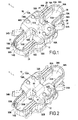
- FIG 2 Another example of an intervertebral device is shown in FIG 2 .
- This example differs from that of FIGS 1 and 3 in that the porous layers 52A, 52B located at the bottom of each groove 14A, 14B, belong to one insert 60 extending within the spacer 10, between the grooves 14A, 14B.
- the porous layer 52A, 52B are defined by two opposite ends of the insert 60.
- the insert 60 may be partially (i.e. at least at its ends extending into the groove 14A (14B) for engagement with the spinous process) or completely porous. It may be partially or completely made of one or several bone-ingrowth materials such as, for instance, Trabecular MetalTM.
- the insert 60 may be fitted into a through hole 61 of complementary shape provided in the spacer 10, or the spacer 10 may be molded or otherwise formed around the insert 60, for example.
- each porous layer 51A, 52A, 53A may protrude from the inner face of the groove 14A (14B), which allows a closer contact between the porous layer and the spinous process SP1 (SP2) and, therefore, fosters bone growth in the porous layer.
- proximal portions 32A, 32B and/or distal portions 34A, 34B of the ties 30A, 30B may be pre-assembled to the spacer 10 before packaging the device.
- the ties 30A, 30B may be intraoperatively assembled with the spacer 10.
- the device 1 may be packaged in a sterilized container (e.g. a bag) under an aseptic condition. The packaged device 1 may be then stored and/or delivered to a physician, or other operative.
- the intervertebral device 1 may be used as follows:
- the spinous processes SP1, SP2 are directly bound or fused to the porous layers 51A-53A, 51B-53B which are fixed to the spacer 10. Accordingly, the spinous processes SP1, SP2 are secured together via the spacer 10 and stabilization is provided between the vertebrae having the spinous processes SP1, SP2.
Abstract
Description
- The present disclosure relates to an intervertebral device to be placed between two spinous processes of two adjacent vertebrae. Such a device is sometimes called an "interspinous device" or an "interspinous implant". It is used for holding two vertebrae in a desired relative position.
- The spine is formed of superposed vertebrae, from the lumbar vertebrae to the cervical vertebrae, each having an anterior part, which is the vertebral body, and a posterior part, which is the vertebral arch (or neural arch), the anterior and posterior parts enclosing the vertebral foramen. Each vertebral arch is formed by a pair of pedicles and a pair of laminae, and has transverse processes and/or a spinous process (or neural spine) projecting therefrom. The transverse and spinous processes project opposite to the vertebral foramen.
- An intervertebral disc lies between each pair of adjacent vertebrae, i.e. between the vertebral bodies of these vertebrae. Each disc forms a cartilaginous joint to hold the two adjacent vertebrae together while allowing relative movements between these vertebrae. When an intervertebral disk is damaged (e.g. worn out or degenerated), it becomes unable to prevent excessive relative movements between the two vertebrae contiguous to the disk, during flexion (forward movement) or extension (backward movement) of the spine.
- An abnormal excessive relative movement between two adjacent vertebrae, whether due to a damaged disk or any other reasons, may cause discomfort and/or pain to the patient.
- As a remedy to this problem, it is known to place an intervertebral device between the spinous processes of the two adjacent vertebrae. Such a device limits the extent to which the posterior parts of the two vertebrae can move with respect to each other when the spine is extended and/or flexed. In other words, the device provides stabilization between the vertebrae. This stabilization may be more or less "dynamic" depending on the amount of relative movement allowed between the vertebrae. The less the amount of relative movement allowed, the less dynamic or the more "static" the stabilization.
- Known examples of intervertebral devices are disclosed, for instance, in
US patents No. 7087083 ,7163558 and7520887 . Those devices provide dynamic stabilization. - Another example of an intervertebral device is disclosed in
US patent No. 5645599 . This device provides more static stabilization than the above-mentioned ones. However, implantation of this device can be traumatic and invasive because pins or crimped spikes are inserted into the spinous processes of the vertebrae. - Further, so-called fusion is known in which vertebrae are fixedly connected to each other. It is known, for example, to use so-called cages which are inserted between the vertebrae, as disclosed in European patent No.
1299054 . Such surgery is much more invasive that an interspinous surgery, as commonly e.g. the disc needs to be removed and the surgeon needs to work around the spinal nerves. It is moreover known to affect fusion by means of rigid posterior rod systems which are attached to either pedicles or laminae of the vertebrae by means of hooks or screws. Such systems require access to further structures of the vertebrae themselves, compared to access to the spinous processes only. Such systems are known for example from European patent No.348272 - According to one embodiment, there is provided an intervertebral device to be placed between two spinous processes of two vertebrae. The intervertebral device comprises a spacer having two opposite or opposing grooves, each groove being configured to engage a spinous process, wherein at least one porous layer is provided on an inner face of each groove, this porous layer being adapted to interface with the spinous process by allowing bone growth in the porous layer.
- Such a device allows, besides other advantages, rigid or largely rigid connection between two vertebrae by a surgery which is as little invasive as dynamic stabilization by means of an interspinous spacer.
- The porous layer may be made of material(s) commonly known as "bone-ingrowth material(s)" configured to allow bone ingrowth into the pores of the porous material. It is made of one or several porous materials, such as porous metals and/or porous ceramics, for example. The porous layer may comprise sub-layers of different materials and/or properties (e.g. different porosities). For example, the porous layer may be formed using Trabecular Metal™ technology available from Zimmer, Inc., of Warsaw, Indiana. Trabecular Metal™ is a trademark of Zimmer Technology, Inc. Such a material may be formed from a reticulated vitreous carbon foam substrate which is infiltrated and coated with a biocompatible metal, such as tantalum, etc., by a chemical vapor deposition ("CVD") process in the manner disclosed in detail in
U.S. Patent No. 5282861, issued February 1, 1994 , entitled "open cell tantalum structures for cancellous bone implants and cell and tissue receptors", the entirety of which is included herein by reference, and in Levine, B.R., et al., "Experimental and Clinical Performance of Porous Tantalum in Orthopedic Surgery", Biomaterials 27 (2006) 4671-4681. Further methods of producing porous metal structures, such as Trabecular Metal™ structures, are provided inWO 2012/065729 . In addition to tantalum, other metals such as niobium or alloys of tantalum and niobium with one another or with other metals may also be used. Bone-ingrowth materials other than Trabecular Metal™ may also be used. For instance, Trabecular Titanium™ available from Lima Corporate may be used. - The porous layers may be fixed onto the inner faces of the grooves by pressing, friction, swaging, clamping, gluing, interlocking or any other appropriate fixing technique. For instance, the porous layers may be fitted into recesses of complementary shape provided in the spacer.
- After bone growth is achieved into the porous layer, the two spinous processes are directly bound to the porous layers which are fixed to the spacer. Accordingly, the spinous processes are held together via the spacer.
- The spacer and, more particularly, the central part of it may be slightly deformable in some instances. When the central part is slightly deformable, it may allow a limited amount of relative movement between the vertebrae. In other instances, the spacer may generally not be deformable, i.e., rigid. When the central part is not deformable, the amount of relative movement allowed between the vertebrae is zero: the intervertebral device provides static stabilization. Such a device providing static stabilization may provide a desired effect for spinal fusion surgery. Spinal fusion is a surgical technique used to permanently join adjacent vertebrae by creating a motionless junction between the vertebrae (i.e. the vertebrae are immobilized with respect to each other).
- The spacer may be made of any desired material, such as polymer and/or metallic materials. For example, in some instances the spacer may be formed of polyetheretherketone (PEEK) or titanium alloy.
- In some embodiments, the intervertebral device may include one or more securement features configured to engage the spinous processes in order to secure the intervertebral device to the spinous processes prior to establishing bone ingrowth into the pores of the porous layer.
- In certain embodiments, the intervertebral device comprises at least one elongated member adapted to surround the spinous processes for maintaining the spinous processes engaged into the grooves. Thus, the elongated member allows the spinous processes to be held in position with respect to the spacer and the porous layers, which fosters bone growth in the porous layer. Alternatively or cumulatively,, the intervertebral device may include pins, spikes, or other fasteners to initially secure the intervertebral device to the spinous processes. However, passing the elongated member(s) around the spinous processes is less invasive than passing pins or spikes through the spinous processes.
- The elongated member may be a tie having a band shape, a cord shape or other shapes. For example, it may be made by weaving or as a cable. It may be made from a polymeric material such as, for example, polyester, polyethylene (for example, polyethylene terephthalate, i.e. PET), polyetheretherketone (PEEK).
- A single elongated member may be passed around the two spinous processes or one elongated member may be passed around each spinous process. The elongated member or members may form a loop around each spinous process, this loop being tightened against the spinous process, for instance by pulling on the end(s) of the elongated member. The elongated member may be fastened to the spacer by any appropriate fastening technique and/or system, such as knotting, sewing, a self-locking system, a clip-fixing system, a clamping system, or a combination thereof.
- In certain embodiments, each groove is defined between two branches and a porous layer is provided at least on the inner face of the distal part of each branch. Thus, after bone growth is achieved into the porous layers, the two branches are joined via the spinous process fitted in the groove. Alternatively or cumulatively, a porous layer may be provided at a base or bottom of each groove. Thus, after bone growth in the porous layers, the two spinous processes fitted in the grooves are joined via the spacer.
- The porous layer may comprise or be made from a material consisting of a web of interconnected rods. The rods may leave interconnected voids between them. The rods may have a metallic surface and/or be made from a metal or alloy. The metallic surface may be made from tantalum, niobium, titanium or an alloy of any two or more thereof. The rods may consist of metal coated pyrolized polymeric material.
- In certain embodiments, the porous layer may have a highly open porosity that imitates the morphology of cancellous bone. For instance, the above-mentioned rods may form a three dimensional structure, said structure being, in particular, a trabecular structure as found in cancellous bone.
- In certain embodiments, each groove is defined between two branches extending from a central part of the spacer and at least one branch is deformable toward the other branch. The two branches may be deformable toward each other. Then, the branches may be deformed toward each other to clamp the spinous process between them. In some embodiments, at least a portion of each branch, in particular the distal part of the branch (i.e., the end of the branch furthest from the central part of the spacer), is deformable. For example, tensioning the elongated member(s) may draw the distal parts of the branches toward one another and bring the porous layer into contact with the spinous processes. When a porous layer is provided on the inner face of the distal parts, the contact between the porous layers and the spinous process is thus improved.
- In certain embodiments, the elongated member passes along an outer face of each branch. When the branches are deformable, they may thus be deformed and brought into closer contact with the spinous process by tightening the elongated member around the branches and the spinous process.
- In certain embodiments, an insert extends within the spacer, between the two opposite grooves, the insert having two opposite ends, each end defining a porous layer at the bottom of each groove. Accordingly, bone growths from the two spinous processes take place in the same insert, thus creating a rigid bone fusion between the adjacent spinous processes.
- According to another aspect of the present disclosure, there is provided a method for stabilizing at least two adjacent vertebrae, comprising the steps of providing an intervertebral device according to the present disclosure and impeding relative movement between the vertebrae by placing the intervertebral device between two spinous processes of the vertebrae.
- Such a method is used, in particular, in spinal fusion surgery.
- This method has the advantages derived from using an intervertebral device according to the present disclosure.
- Other features and advantages of the invention will become apparent from the following detailed description, taken in conjunction with the accompanying drawings, which illustrate, by way of example, the principles of the invention.
- In the drawings, like reference signs generally refer to the same parts throughout the different views.
-
FIG 1 is a perspective view of an example of an intervertebral spacer. -
FIG 2 is a perspective view of another example of an intervertebral spacer. -
FIG 3 is a front view of the intervertebral device ofFIG 1 in position between two spinous processes. - In the following detailed description, it is referred to the accompanying drawings showing examples of intervertebral devices. It is intended that these examples be considered as illustrative only, the scope of the invention not being limited to these examples.
- To avoid details not necessary to enable those skilled in the art to practice the invention, the present description may omit certain information known to those skilled in the art.
- The appended drawings show examples of intervertebral devices 1. Those devices are adapted to be placed between two adjacent spinous processes SP1, SP2 of two vertebrae, as illustrated in
FIG 3 . - In the example of
FIGS 1 and3 , the intervertebral device 1 comprises aspacer 10 having twoopposite grooves groove 14A (14B) is defined between two legs orbranches branches FIG 3 ) to cover more than one-half (1/2) of the height H2 of the spinous process SP1 (SP2) concerned, in particular, more than two-thirds (2/3) of the height H2 and, especially, about or more than three-quarters (3/4) of the height H2, the heights H1 and H2 being measured along the central axis of the groove. In other words, the legs orbranches - In the illustrated example, the device 1 is quasi-symmetrical with respect to a center point 0 (see
FIG 1 ) located in the middle of thecentral part 12 of thespacer 10. Thus, thespacer 10 comprises twoquasi-symmetrical halves - The device 1 may comprise two elongated members (see
FIG 2 ), each being formed by atie tie 30A (30B) having a first,proximal end 32A (32B) and a second,distal end 34A (34B). Theproximal end 32A (32B) of eachtie 30A (30B) may be permanently fastened to thespacer 10. For instance, theproximal end 32A (32B) may be sewed into a loop, this loop surrounding a part of thespacer 10. Thedistal end 34A (34B) of eachtie 30A (30B) may be passed through afastening system 40A (40B). Here, thefastening system 40A (40B) is a self-locking system analogous to the one described in French patent application No.FR2897771 spacer 10. - Each
tie 30A (30B) may extend across thegroove 14A (14B) from onebranch 16A (18A) to theother branch 16B (18B) to capture the spinous process SP1 (SP2) in thegroove 14A (14B). For example, from itsproximal end 32A (32B) to itsdistal end 34A (34B), eachtie 30A (30B) may pass along theouter face 26 of onebranch 16A (18A), over thegroove 14A (14B), along the outer face 29 of theother branch 16B (18B), and through thefastening system 40A (40B). - The
branches tie 30A along their outer face. In the illustrated example, eachbranch rib 31 extending longitudinally along the outer face of the branch, from thespacer 10 to the distal end of the branch. Therib 31 may be located on one lateral edge of the branch. For instance, on the lateral edge close to the vertebral foramen when thespacer 10 is implanted. Thetie 30A may abut against or extend along therib 31 and, thus, is guided and prevented from sliding off the branch. Alternatively, eachbranch ribs 31, one on each of its lateral edges, with thetie 30A extending therebetween. - As illustrated in
FIG 3 , eachtie 30A (30B) is tightened around the spinous processes SP1 (SP2), by pulling on the free,distal end 34A (34B) of thetie 30A (30B). Thus, the spinous processes SP1, SP2 may be retained by theties grooves FIG 3 ). In addition, when the distal parts of thebranch tie - As illustrated,
porous layers groove 14A (14B), or otherwise positioned to face and contact the spinous process SP1 (SP2) retained in thegroove 14A (14B). In particular, twoporous layers branches groove 14A and oneporous layer 52A may be fixed on the bottom of thegroove 14A. Eachporous layer porous layers recesses spacer 10. In some instances, theporous layers groove 14A (14B), or theporous layers groove 14A (14B). - Another example of an intervertebral device is shown in
FIG 2 . This example differs from that ofFIGS 1 and3 in that theporous layers groove insert 60 extending within thespacer 10, between thegrooves porous layer insert 60. Theinsert 60 may be partially (i.e. at least at its ends extending into thegroove 14A (14B) for engagement with the spinous process) or completely porous. It may be partially or completely made of one or several bone-ingrowth materials such as, for instance, Trabecular Metal™. Theinsert 60 may be fitted into a throughhole 61 of complementary shape provided in thespacer 10, or thespacer 10 may be molded or otherwise formed around theinsert 60, for example. - In general, each
porous layer groove 14A (14B), which allows a closer contact between the porous layer and the spinous process SP1 (SP2) and, therefore, fosters bone growth in the porous layer. - Now that the structure of the intervertebral device 1 has been described, the operation of the device 1 is quickly described below.
- In some instances the
proximal portions distal portions ties spacer 10 before packaging the device. However, in other instances theties spacer 10. The device 1 may be packaged in a sterilized container (e.g. a bag) under an aseptic condition. The packaged device 1 may be then stored and/or delivered to a physician, or other operative. - In operative conditions, the intervertebral device 1 may be used as follows:
- a posterior access to spinous processes SP1, SP2 is created through an incision in the patient;
- the device 1 is inserted between the spinous processes SP1, SP2;
- the
ties fastening systems - tension is applied to the
ties distal ends ties grooves 14A, 14B.Thus, once theties spacer 10 with the spinous processes SP1, SP2 contacting or pressing against theporous layers 51A-53A, 51B-53B. The apposition of the spinous processes SP1, SP2 with the porous layers fosters subsequent bone growth from the spinous processes SP1, SP2 into theporous layers 51A-53A, 51B-53B. It is noted that bone bleeding improves the bone growth from the spinous processes into the porous layers. Accordingly, the spinous processes may be abraded before putting thespacer 10 in place. - Once bone has grown into the pores of the
porous layers 51A-53A, 51B-53B, the spinous processes SP1, SP2 are directly bound or fused to theporous layers 51A-53A, 51B-53B which are fixed to thespacer 10. Accordingly, the spinous processes SP1, SP2 are secured together via thespacer 10 and stabilization is provided between the vertebrae having the spinous processes SP1, SP2. - "Comprises/comprising" when used herein is taken to specify the presence of stated features but does not preclude the presence or addition of one or more other features.
- The above description is given by way of example, and not limitation. Given the above disclosure, one skilled in the art could devise variations that are within the scope of the invention. Further, the various features of the embodiments or examples disclosed herein can be used alone or in varying combinations with each other, and are not intended to be limited to the specific combinations disclosed herein.
Claims (15)
- An intervertebral device to be placed between two spinous processes of two adjacent vertebrae, comprising a spacer (10) having two opposite grooves (14A, 14B), each groove being configured to engage a spinous process (SP1, SP2), wherein at least one porous layer (51A, 52A, 53A, 51B, 52B, 53B) is provided on an inner face of each groove, this porous layer being adapted to interface with the spinous process by allowing bone growth in the porous layer.
- The intervertebral device of claim 1, comprising at least one elongated member (30A, 30B) adapted to surround the spinous processes (SP1, SP2) for maintaining the spinous processes engaged into the grooves (14A, 14B).
- The intervertebral device of claim 1 or 2, wherein each groove (14A, 14B) is defined between two branches (16A, 18A, 16B, 18B) extending from a central part of the spacer (10) and wherein a porous layer (51A, 53A, 51B, 53B) is provided on the inner face of each branch.
- The intervertebral device of any one of claims 1 to 3, wherein each groove (14A, 14B) is defined between two branches (16A, 18A, 16B, 18B) extending from a central part of the spacer and wherein at least one branch is deformable toward the other branch.
- The intervertebral device of claim 3 or 4, wherein the elongated member (30A, 30B) passes along an outer face of each branch.
- The intervertebral device of any one of claims 1 to 5, wherein a porous layer (52A, 52B) is provided at a base of each groove (14A, 14B).
- The intervertebral device of any one of claims 1 to 6, wherein an insert (60) extends within the spacer (10), between the two opposite grooves (14A, 14B), the insert (60) having two opposite ends, each end defining a porous layer (52A, 52B) at a base of each groove.
- The intervertebral device of any one of claims 1 to 7, wherein the porous layer (51A, 52A, 53A, 51B, 52B, 53B) comprises porous metal.
- The intervertebral device of any one of claims 1 to 8, wherein the porous layer (51A, 52A, 53A, 51B, 52B, 53B) is made from a material consisting of a web of interconnected rods.
- The intervertebral device of claim 9, wherein the rods leave interconnected voids between them.
- The intervertebral device of claim 9 or 10, wherein the rods form a three dimensional structure, said structure in particular being a trabecular structure as found in cancellous bone.
- The intervertebral device of any one of claims 9 to 11, wherein the rods have a metallic surface and/or are made from a metal or an alloy.
- The intervertebral device of claim 12, wherein the metallic surface is made from tantalum, niobium, titanium or an alloy of any two or more thereof.
- The intervertebral device of any one of claims 9 to 13, wherein the rods consist of metal coated pyrolized polymeric material.
- A method for stabilizing at least two adjacent vertebrae, comprising the steps of providing an intervertebral device (1) according to any one of claims 1 to 14 and impeding relative movement between the vertebrae by placing the intervertebral device (1) between two spinous processes (SP1, SP2) of the vertebrae.
Priority Applications (2)
| Application Number | Priority Date | Filing Date | Title |
|---|---|---|---|
| EP13305591.3A EP2801328A1 (en) | 2013-05-06 | 2013-05-06 | Intervertebral device |
| PCT/EP2014/059234 WO2014180844A1 (en) | 2013-05-06 | 2014-05-06 | Intervertebral device |
Applications Claiming Priority (1)
| Application Number | Priority Date | Filing Date | Title |
|---|---|---|---|
| EP13305591.3A EP2801328A1 (en) | 2013-05-06 | 2013-05-06 | Intervertebral device |
Publications (1)
| Publication Number | Publication Date |
|---|---|
| EP2801328A1 true EP2801328A1 (en) | 2014-11-12 |
Family
ID=48613540
Family Applications (1)
| Application Number | Title | Priority Date | Filing Date |
|---|---|---|---|
| EP13305591.3A Withdrawn EP2801328A1 (en) | 2013-05-06 | 2013-05-06 | Intervertebral device |
Country Status (2)
| Country | Link |
|---|---|
| EP (1) | EP2801328A1 (en) |
| WO (1) | WO2014180844A1 (en) |
Citations (15)
| Publication number | Priority date | Publication date | Assignee | Title |
|---|---|---|---|---|
| EP0348272A1 (en) | 1988-06-24 | 1989-12-27 | Societe De Fabrication De Materiel Orthopedique | Implant for a spiral osteosynthesis device, especially in traumatology |
| US5282861A (en) | 1992-03-11 | 1994-02-01 | Ultramet | Open cell tantalum structures for cancellous bone implants and cell and tissue receptors |
| US5645599A (en) | 1994-07-26 | 1997-07-08 | Fixano | Interspinal vertebral implant |
| EP1299054A1 (en) | 2000-07-12 | 2003-04-09 | Spine Next | Intersomatic implant |
| US7087083B2 (en) | 2001-03-13 | 2006-08-08 | Abbott Spine | Self locking fixable intervertebral implant |
| US7163558B2 (en) | 2001-11-30 | 2007-01-16 | Abbott Spine | Intervertebral implant with elastically deformable wedge |
| FR2897771A1 (en) | 2006-02-28 | 2007-08-31 | Abbott Spine Sa | Intervertebral implant for e.g. spines of patient`s vertebrae, has recesses defined by extensions extending respective insertion faces, where height of one of extensions with respect to base wall is lesser than height of other extension |
| US20080319550A1 (en) * | 2004-10-20 | 2008-12-25 | Moti Altarac | Interspinous spacer |
| US7520887B2 (en) | 2003-02-19 | 2009-04-21 | Warsaw Orthopedic, Inc. | Interspinous device for impeding the movements of two successive vertebrae, and method for making a pad designed for it |
| US20100179595A1 (en) * | 2009-01-09 | 2010-07-15 | Pioneer Surgical Technology, Inc. | Intervertebral Implant Devices and Methods for Insertion Thereof |
| US20100241167A1 (en) * | 2007-01-11 | 2010-09-23 | Lanx, Inc. | Spinous process implants and associated methods |
| US20110172711A1 (en) * | 2010-01-14 | 2011-07-14 | X-Spine Systems, Inc. | Modular interspinous fixation system and method |
| WO2012065729A1 (en) | 2010-11-17 | 2012-05-24 | Zimmer Gmbh | Porous metal structures made from polymer preforms |
| WO2013006830A1 (en) * | 2011-07-07 | 2013-01-10 | Samy Abdou | Devices and methods to prevent or limit spondlylolisthesis and other aberrant movements of the vertebral bones |
| WO2013022880A1 (en) * | 2011-08-08 | 2013-02-14 | Zimmer Spine, Inc. | Bone anchoring device |
-
2013
- 2013-05-06 EP EP13305591.3A patent/EP2801328A1/en not_active Withdrawn
-
2014
- 2014-05-06 WO PCT/EP2014/059234 patent/WO2014180844A1/en active Application Filing
Patent Citations (15)
| Publication number | Priority date | Publication date | Assignee | Title |
|---|---|---|---|---|
| EP0348272A1 (en) | 1988-06-24 | 1989-12-27 | Societe De Fabrication De Materiel Orthopedique | Implant for a spiral osteosynthesis device, especially in traumatology |
| US5282861A (en) | 1992-03-11 | 1994-02-01 | Ultramet | Open cell tantalum structures for cancellous bone implants and cell and tissue receptors |
| US5645599A (en) | 1994-07-26 | 1997-07-08 | Fixano | Interspinal vertebral implant |
| EP1299054A1 (en) | 2000-07-12 | 2003-04-09 | Spine Next | Intersomatic implant |
| US7087083B2 (en) | 2001-03-13 | 2006-08-08 | Abbott Spine | Self locking fixable intervertebral implant |
| US7163558B2 (en) | 2001-11-30 | 2007-01-16 | Abbott Spine | Intervertebral implant with elastically deformable wedge |
| US7520887B2 (en) | 2003-02-19 | 2009-04-21 | Warsaw Orthopedic, Inc. | Interspinous device for impeding the movements of two successive vertebrae, and method for making a pad designed for it |
| US20080319550A1 (en) * | 2004-10-20 | 2008-12-25 | Moti Altarac | Interspinous spacer |
| FR2897771A1 (en) | 2006-02-28 | 2007-08-31 | Abbott Spine Sa | Intervertebral implant for e.g. spines of patient`s vertebrae, has recesses defined by extensions extending respective insertion faces, where height of one of extensions with respect to base wall is lesser than height of other extension |
| US20100241167A1 (en) * | 2007-01-11 | 2010-09-23 | Lanx, Inc. | Spinous process implants and associated methods |
| US20100179595A1 (en) * | 2009-01-09 | 2010-07-15 | Pioneer Surgical Technology, Inc. | Intervertebral Implant Devices and Methods for Insertion Thereof |
| US20110172711A1 (en) * | 2010-01-14 | 2011-07-14 | X-Spine Systems, Inc. | Modular interspinous fixation system and method |
| WO2012065729A1 (en) | 2010-11-17 | 2012-05-24 | Zimmer Gmbh | Porous metal structures made from polymer preforms |
| WO2013006830A1 (en) * | 2011-07-07 | 2013-01-10 | Samy Abdou | Devices and methods to prevent or limit spondlylolisthesis and other aberrant movements of the vertebral bones |
| WO2013022880A1 (en) * | 2011-08-08 | 2013-02-14 | Zimmer Spine, Inc. | Bone anchoring device |
Non-Patent Citations (1)
| Title |
|---|
| LEVINE, B.R. ET AL.: "Experimental and Clinical Performance of Porous Tantalum in Orthopedic Surgery", BIOMATERIALS, vol. 27, 2006, pages 4671 - 4681, XP025097469, DOI: doi:10.1016/j.biomaterials.2006.04.041 |
Also Published As
| Publication number | Publication date |
|---|---|
| WO2014180844A1 (en) | 2014-11-13 |
Similar Documents
| Publication | Publication Date | Title |
|---|---|---|
| US8382801B2 (en) | Spinous process implants, instruments, and methods | |
| US8172882B2 (en) | Implant system and method to treat degenerative disorders of the spine | |
| JP6355925B2 (en) | Intervertebral joint fusion implant and fusion method | |
| US8114136B2 (en) | Implants and methods for inter-spinous process dynamic stabilization of a spinal motion segment | |
| JP4667465B2 (en) | Interspinous process graft containing binder | |
| EP2992844B1 (en) | Interspinous vertebral and lumbosacral stabilization devices | |
| JP7317797B2 (en) | Connector for use in systems and methods for reducing the risk of proximal-adjacent intervertebral kyphosis deformity | |
| JP7330944B2 (en) | Systems and methods for reducing the risk of proximal-adjacent intervertebral kyphosis deformity using bone anchors or other attachment points | |
| US20050055096A1 (en) | Functional spinal unit prosthetic | |
| US20130103088A1 (en) | Segmental Spinous Process Anchor System and Methods of Use | |
| US20090248082A1 (en) | Surgical systems and methods for joint fixation | |
| JP2010516397A (en) | Interspinous process implant including binder and method of transplantation | |
| JP2013501582A (en) | Interspinous implant and method | |
| EP2892453A1 (en) | Spine stabilization device | |
| US20220071663A1 (en) | Novel surgical methods for the treatment of spinal stenosis | |
| US20120271352A1 (en) | Facet joint implant | |
| EP2801328A1 (en) | Intervertebral device | |
| AU2005244913A1 (en) | Functional spinal unit prosthetic | |
| US20230172643A1 (en) | Implantable device, in particular of the intervertebral spacer type | |
| US20200170677A1 (en) | Novel surgical methods for the treatment of spinal stenosis | |
| AU2014313892B2 (en) | Spine stabilization device |
Legal Events
| Date | Code | Title | Description |
|---|---|---|---|
| PUAI | Public reference made under article 153(3) epc to a published international application that has entered the european phase |
Free format text: ORIGINAL CODE: 0009012 |
|
| 17P | Request for examination filed |
Effective date: 20130506 |
|
| AK | Designated contracting states |
Kind code of ref document: A1 Designated state(s): AL AT BE BG CH CY CZ DE DK EE ES FI FR GB GR HR HU IE IS IT LI LT LU LV MC MK MT NL NO PL PT RO RS SE SI SK SM TR |
|
| AX | Request for extension of the european patent |
Extension state: BA ME |
|
| R17P | Request for examination filed (corrected) |
Effective date: 20150512 |
|
| RBV | Designated contracting states (corrected) |
Designated state(s): AL AT BE BG CH CY CZ DE DK EE ES FI FR GB GR HR HU IE IS IT LI LT LU LV MC MK MT NL NO PL PT RO RS SE SI SK SM TR |
|
| STAA | Information on the status of an ep patent application or granted ep patent |
Free format text: STATUS: EXAMINATION IS IN PROGRESS |
|
| 17Q | First examination report despatched |
Effective date: 20180319 |
|
| STAA | Information on the status of an ep patent application or granted ep patent |
Free format text: STATUS: EXAMINATION IS IN PROGRESS |
|
| GRAP | Despatch of communication of intention to grant a patent |
Free format text: ORIGINAL CODE: EPIDOSNIGR1 |
|
| STAA | Information on the status of an ep patent application or granted ep patent |
Free format text: STATUS: GRANT OF PATENT IS INTENDED |
|
| INTG | Intention to grant announced |
Effective date: 20210816 |
|
| STAA | Information on the status of an ep patent application or granted ep patent |
Free format text: STATUS: THE APPLICATION IS DEEMED TO BE WITHDRAWN |
|
| 18D | Application deemed to be withdrawn |
Effective date: 20220104 |