EP2800290A1 - Method and device for transmitting channel state information - Google Patents
Method and device for transmitting channel state information Download PDFInfo
- Publication number
- EP2800290A1 EP2800290A1 EP12863608.1A EP12863608A EP2800290A1 EP 2800290 A1 EP2800290 A1 EP 2800290A1 EP 12863608 A EP12863608 A EP 12863608A EP 2800290 A1 EP2800290 A1 EP 2800290A1
- Authority
- EP
- European Patent Office
- Prior art keywords
- csi
- resources
- resource
- over
- ports
- Prior art date
- Legal status (The legal status is an assumption and is not a legal conclusion. Google has not performed a legal analysis and makes no representation as to the accuracy of the status listed.)
- Granted
Links
Images

Classifications
-
- H—ELECTRICITY
- H04—ELECTRIC COMMUNICATION TECHNIQUE
- H04L—TRANSMISSION OF DIGITAL INFORMATION, e.g. TELEGRAPHIC COMMUNICATION
- H04L5/00—Arrangements affording multiple use of the transmission path
- H04L5/003—Arrangements for allocating sub-channels of the transmission path
- H04L5/0053—Allocation of signalling, i.e. of overhead other than pilot signals
-
- H—ELECTRICITY
- H04—ELECTRIC COMMUNICATION TECHNIQUE
- H04B—TRANSMISSION
- H04B7/00—Radio transmission systems, i.e. using radiation field
- H04B7/02—Diversity systems; Multi-antenna system, i.e. transmission or reception using multiple antennas
- H04B7/022—Site diversity; Macro-diversity
- H04B7/024—Co-operative use of antennas of several sites, e.g. in co-ordinated multipoint or co-operative multiple-input multiple-output [MIMO] systems
-
- H—ELECTRICITY
- H04—ELECTRIC COMMUNICATION TECHNIQUE
- H04B—TRANSMISSION
- H04B7/00—Radio transmission systems, i.e. using radiation field
- H04B7/02—Diversity systems; Multi-antenna system, i.e. transmission or reception using multiple antennas
- H04B7/04—Diversity systems; Multi-antenna system, i.e. transmission or reception using multiple antennas using two or more spaced independent antennas
- H04B7/06—Diversity systems; Multi-antenna system, i.e. transmission or reception using multiple antennas using two or more spaced independent antennas at the transmitting station
- H04B7/0613—Diversity systems; Multi-antenna system, i.e. transmission or reception using multiple antennas using two or more spaced independent antennas at the transmitting station using simultaneous transmission
- H04B7/0615—Diversity systems; Multi-antenna system, i.e. transmission or reception using multiple antennas using two or more spaced independent antennas at the transmitting station using simultaneous transmission of weighted versions of same signal
- H04B7/0619—Diversity systems; Multi-antenna system, i.e. transmission or reception using multiple antennas using two or more spaced independent antennas at the transmitting station using simultaneous transmission of weighted versions of same signal using feedback from receiving side
- H04B7/0621—Feedback content
- H04B7/0626—Channel coefficients, e.g. channel state information [CSI]
-
- H—ELECTRICITY
- H04—ELECTRIC COMMUNICATION TECHNIQUE
- H04B—TRANSMISSION
- H04B7/00—Radio transmission systems, i.e. using radiation field
- H04B7/02—Diversity systems; Multi-antenna system, i.e. transmission or reception using multiple antennas
- H04B7/04—Diversity systems; Multi-antenna system, i.e. transmission or reception using multiple antennas using two or more spaced independent antennas
- H04B7/06—Diversity systems; Multi-antenna system, i.e. transmission or reception using multiple antennas using two or more spaced independent antennas at the transmitting station
- H04B7/0613—Diversity systems; Multi-antenna system, i.e. transmission or reception using multiple antennas using two or more spaced independent antennas at the transmitting station using simultaneous transmission
- H04B7/0615—Diversity systems; Multi-antenna system, i.e. transmission or reception using multiple antennas using two or more spaced independent antennas at the transmitting station using simultaneous transmission of weighted versions of same signal
- H04B7/0619—Diversity systems; Multi-antenna system, i.e. transmission or reception using multiple antennas using two or more spaced independent antennas at the transmitting station using simultaneous transmission of weighted versions of same signal using feedback from receiving side
- H04B7/0621—Feedback content
- H04B7/0634—Antenna weights or vector/matrix coefficients
-
- H—ELECTRICITY
- H04—ELECTRIC COMMUNICATION TECHNIQUE
- H04B—TRANSMISSION
- H04B7/00—Radio transmission systems, i.e. using radiation field
- H04B7/02—Diversity systems; Multi-antenna system, i.e. transmission or reception using multiple antennas
- H04B7/04—Diversity systems; Multi-antenna system, i.e. transmission or reception using multiple antennas using two or more spaced independent antennas
- H04B7/06—Diversity systems; Multi-antenna system, i.e. transmission or reception using multiple antennas using two or more spaced independent antennas at the transmitting station
- H04B7/0613—Diversity systems; Multi-antenna system, i.e. transmission or reception using multiple antennas using two or more spaced independent antennas at the transmitting station using simultaneous transmission
- H04B7/0615—Diversity systems; Multi-antenna system, i.e. transmission or reception using multiple antennas using two or more spaced independent antennas at the transmitting station using simultaneous transmission of weighted versions of same signal
- H04B7/0619—Diversity systems; Multi-antenna system, i.e. transmission or reception using multiple antennas using two or more spaced independent antennas at the transmitting station using simultaneous transmission of weighted versions of same signal using feedback from receiving side
- H04B7/0636—Feedback format
- H04B7/0643—Feedback on request
-
- H—ELECTRICITY
- H04—ELECTRIC COMMUNICATION TECHNIQUE
- H04L—TRANSMISSION OF DIGITAL INFORMATION, e.g. TELEGRAPHIC COMMUNICATION
- H04L1/00—Arrangements for detecting or preventing errors in the information received
- H04L1/0001—Systems modifying transmission characteristics according to link quality, e.g. power backoff
- H04L1/0023—Systems modifying transmission characteristics according to link quality, e.g. power backoff characterised by the signalling
- H04L1/0026—Transmission of channel quality indication
-
- H—ELECTRICITY
- H04—ELECTRIC COMMUNICATION TECHNIQUE
- H04L—TRANSMISSION OF DIGITAL INFORMATION, e.g. TELEGRAPHIC COMMUNICATION
- H04L5/00—Arrangements affording multiple use of the transmission path
- H04L5/003—Arrangements for allocating sub-channels of the transmission path
- H04L5/0032—Distributed allocation, i.e. involving a plurality of allocating devices, each making partial allocation
- H04L5/0035—Resource allocation in a cooperative multipoint environment
-
- H—ELECTRICITY
- H04—ELECTRIC COMMUNICATION TECHNIQUE
- H04L—TRANSMISSION OF DIGITAL INFORMATION, e.g. TELEGRAPHIC COMMUNICATION
- H04L5/00—Arrangements affording multiple use of the transmission path
- H04L5/003—Arrangements for allocating sub-channels of the transmission path
- H04L5/0048—Allocation of pilot signals, i.e. of signals known to the receiver
-
- H—ELECTRICITY
- H04—ELECTRIC COMMUNICATION TECHNIQUE
- H04L—TRANSMISSION OF DIGITAL INFORMATION, e.g. TELEGRAPHIC COMMUNICATION
- H04L5/00—Arrangements affording multiple use of the transmission path
- H04L5/003—Arrangements for allocating sub-channels of the transmission path
- H04L5/0053—Allocation of signalling, i.e. of overhead other than pilot signals
- H04L5/0057—Physical resource allocation for CQI
-
- H—ELECTRICITY
- H04—ELECTRIC COMMUNICATION TECHNIQUE
- H04B—TRANSMISSION
- H04B7/00—Radio transmission systems, i.e. using radiation field
- H04B7/02—Diversity systems; Multi-antenna system, i.e. transmission or reception using multiple antennas
- H04B7/04—Diversity systems; Multi-antenna system, i.e. transmission or reception using multiple antennas using two or more spaced independent antennas
- H04B7/06—Diversity systems; Multi-antenna system, i.e. transmission or reception using multiple antennas using two or more spaced independent antennas at the transmitting station
- H04B7/0613—Diversity systems; Multi-antenna system, i.e. transmission or reception using multiple antennas using two or more spaced independent antennas at the transmitting station using simultaneous transmission
- H04B7/0615—Diversity systems; Multi-antenna system, i.e. transmission or reception using multiple antennas using two or more spaced independent antennas at the transmitting station using simultaneous transmission of weighted versions of same signal
- H04B7/0619—Diversity systems; Multi-antenna system, i.e. transmission or reception using multiple antennas using two or more spaced independent antennas at the transmitting station using simultaneous transmission of weighted versions of same signal using feedback from receiving side
- H04B7/0636—Feedback format
- H04B7/0639—Using selective indices, e.g. of a codebook, e.g. pre-distortion matrix index [PMI] or for beam selection
Definitions
- the present invention relates to the field of communications and particularly to a method and apparatus for transmitting channel state information.
- LTE-A Long Term Evolution-Advanced
- CoMP Coordinated Multiple-Point
- DPS Dynamic Point Selection
- CBF Coordinated Beam-Forming
- JT Joint Transmission
- DPS Dynamic Point Selection
- CBF Coordinated Beam-Forming
- JT Joint Transmission
- DPS and CBF can be combined to select a plurality of points dynamically for coordinated beam-forming.
- a "point" can be defined as a set of geographically co-located transmit antennas, and different sectors with the same site location correspond to different points.
- the system configures different Channel State Information-Reference Signal (CSI-RS) resources so that a User Equipment (UE) can measure downlink channels of respective "points", that is, estimate the downlink channels of the different "points” with use of different CSI-RSs, where a "CSI-RS resource” refers to a combination of a "resource configuration” and a "sub-frame configuration", both of which are configured by higher-layer signaling.
- CSI-RS resource refers to a combination of a "resource configuration” and a "sub-frame configuration”, both of which are configured by higher-layer signaling.
- the "point” may not be a physical point but may be a virtual point, and each virtual point corresponds to a CSI-RS resource and is consisted of one or more physical points, or a physical point includes a plurality of virtual points.
- Channel State Information (CSI) needed for the transmission scheme is fed back after the downlink channels are measured.
- the various transmission schemes need to be supported by corresponding channel state information.
- the DPS needs channel state information of a plurality of points, or channel state information of a specific point and CSI-RS index information corresponding to the specific transmission point.
- the JT needs channel state information of respective transmission points and relative phase information of the respective transmission points, or joint channel state information of a plurality of transmission points.
- the "coordination set" is defined as points participating directly and/or indirectly in transmission of data to a user, and a "transmission point” is defined as a point transmitting data directly to the UE.
- An aggregated feedback of a plurality of CSI-RS resources can be made in practice, that is, CSI of a joint channel of the plurality of CSI-RS resources can be fed back, wherein the CSI can include an RI, a Pre-coding Matrix Indicator (PMI) and a Channel Quality Indicator (CQI).
- PMI Pre-coding Matrix Indicator
- CQI Channel Quality Indicator
- a Physical Downlink Shared Channel (PDSCH) transmission scheme assumed for CSI in the CoMP transmission mode may be defined based upon a UE-Specific Reference Signal (UERS), and the CSI is measured based on a CSI-RS. Consequently it is impossible at present to apply a measurement result based on a CSI-RS to the transmission scheme based on physical downlink shared channel, due to that no feedback in the CoMP transmission mode can be made.
- UERS UE-Specific Reference Signal
- Embodiments of the invention provide a method and apparatus for transmitting channel state information so as to transmit the channel information in CoMP.
- a method for transmitting channel state information, applied to the user equipment side, the method includes:
- a method for transmitting channel state information, applied to the base station side, the method includes:
- a user equipment includes:
- a bases station includes:
- a PDSCH or a UERS signal a k , l p transmitted in the ( k , l ) -th resource element over a UERS resource generates the same result as a signal a ⁇ k , l p transmitted in the ( k , l ) -th resource element over a CSI-RS resource.
- a CSI feedback of a joint channel matrix constructed after a user equipment measures a plurality of CSI-RS resources can be made to thereby support transmission of channel state information in CoMP transmission.
- a PDSCH or a UERS signal a k , l p transmitted in the ( k , l ) -th resource element over a UERS resource generates the same result as a signal a ⁇ k , l p transmitted in the ( k , l )-th resource element over a CSI-RS resource.
- a CSI feedback of a joint channel matrix constructed after a user equipment measures a plurality of CSI-RS resources can be made to thereby support transmission of channel state information in CoMP transmission.
- This embodiment can be applied to CoMP, so a CSI-RS resource corresponds to a point which is a physical point or a virtual point.
- a flow chart of transmitting CSI at a user equipment in this embodiment is as follows:
- Step 101 A user equipment receives, from a base station, control signaling to instruct the user equipment to feed back channel information, where the control signaling includes indication information of a plurality of CSI-RS resources for an aggregated feedback.
- the control signaling can further include feedback mode indication information of the CSI feedback, etc.
- Step 102 The user equipment performs channel estimation based on the plurality of CSI-RS resources obtained from the indication information and constructs a channel matrix according to a result of channel estimation.
- Step 103 The user equipment determines CSI according to a preset PDSCH transmission scheme over a CSI reference resource, a correspondence relationship between signals over the plurality of CSI-RS resources and signals on UERS ports and the constructed channel matrix, and then the user equipment transmits the CSI to the base station at least for the base station to use the technology of CoMP over a UERS based PDSCH.
- the CSI includes a Rank Indication (RI), a Pre-coding Matrix Indicator (PMI) and a Channel Quality Indicator (CQI).
- RI Rank Indication
- PMI Pre-coding Matrix Indicator
- CQI Channel Quality Indicator
- CSI reference resource can be defined as:
- the CSI reference resource is consisted of a bandwidth corresponding to a set of downlink physical resource blocks and particularly determined by the feedback mode.
- the CSI reference resource is defined by a downlink sub-frame n- n CQI_ref , where n represents the sub-frame for the CSI reporting, and n CQI_ref is an integer and determined particularly as follows:
- n CQI_ref is the least value which is no less than 4 such that the CSI reference sub-frame is a valid downlink sub-frame
- n CQI_ref is the difference between the sub-frame containing the downlink control signaling and the subframe for CSI reporting;
- n CQI_ref is 4 and n- n CQI_ref corresponds to a valid downlink sub-frame.
- the CSI reference resource is determined by the RI and the PMI based upon which the CQI is calculated.
- a PDSCH or a UERS signal a k , l p transmitted on UERS antenna port ⁇ 7,...,6+ ⁇ ( ⁇ represents the number of layers and a port number starts with 7) over the (k, l ) -th resource element (including time-domain and frequency-domain resources, where k represents a sub-carrier, and l represents an OFDM symbol) generates the same result as a signal a ⁇ k , l p transmitted on CSI-RS antenna port ⁇ 15,...,14+ P 1 ⁇ 1 , ⁇ 15,...,14+ P 2 ⁇ 2 , ⁇ , ⁇ 15,...,14+ P N ⁇ N ⁇ over the ( k , l )-th resource element, that is, a ⁇ k , l 15 1 ⁇ a ⁇ k , l 14 + P N N ⁇
- the step in which the user equipment determines the CSI according to the constructed channel matrix includes: for the joint of the plurality of CSI-RS resources, the user equipment determines the pre-coding matrix according to the constructed channel matrix and determines the CSI according to the determined pre-coding matrix.
- This solution is primarily applicable to a scenario in which the transmission mode of a PDSCH is the Joint Transmission (JT) mode.
- W W 1 ⁇ W N , where W n represents a pre-coding matrix corresponding to a reported PMI for the n-th CSI-RS resource applied on the ( k , l ) -th resource element.
- the step in which the user equipment determines the CSI according to the constructed channel matrix includes: the user equipment determines a pre-coding matrix according to the constructed channel matrix for each resource element over the plurality of CSI-RS resources, and determines the CSI according to the determined the pre-coding matrix.
- This solution is primarily applicable to a scenario in which the transmission mode of the PDSCH is the incoherent JT.
- W W 1 ⁇ ⁇ N ⁇ W N , where W n represents a pre-coding matrix corresponding to a reported PMI for the n-th CSI-RS resource applied on the ( k , l ) -th resource element, and ⁇ n represents correlation information between the CSI-RS resources and generally correlation information of the n-th CSI-RS resource relative to the 1st CSI-RS resource of the ( k , l ) -th resource element.
- the step in which the user equipment determines the CSI according to the constructed channel matrix includes: the user equipment determines a pre-coding matrix according to the constructed channel matrix and the correlation information between the plurality of CSI-RS resources for each resource element over the plurality of CSI-RS resources, and determines the CSI according to the determined the pre-coding matrix.
- This solution is primarily applicable to a scenario in which the transmission mode of the PDSCH is coherent JT.
- the base station In contrast to the user equipment side, the base station needs to transmit the control signaling to the user equipment to instruct the user equipment to feed back CSI for the plurality of CSI-RS resources.
- a flow of a method for transmitting CSI at a base station in the embodiment is as follows:
- Step 201 Abase station sends control signaling to a user equipment to instruct the user equipment to feed back channel information, where the control signaling includes indication information of a plurality of CSI-RS resources for an aggregated feedback.
- Step 202 The base station receives CSI from the user equipment for the plurality of CSI-RS resources.
- the CSI received, by the base station, from the user equipment for the plurality of CSI-RS resources is determined according to a preset PDSCH transmission scheme over a CSI reference resource, a correspondence relationship between signals over the plurality of CSI-RS resources and signals on UERS ports and a constructed channel matrix.
- a ⁇ k , l 15 1 ⁇ a ⁇ k , l 14 + P N , N W ⁇ a k , l 7 ⁇ a k , l 6 + ⁇ , where a k , l represents a PDSCH or a UERS signal transmitted on UERS antenna port ⁇ 7,..., 6 + ⁇ over the ( k , l ) -th resource element, u represents the number of layers, k represents a sub-carrier index in the frequency domain, and l represents an OFDM symbol index in the time domain, a ⁇ k , l represents a signal transmitted on CSI-RS antenna port ⁇ 15,...,14+ P 1 ⁇ 1 , ⁇ 15,...,14+ P 2 ⁇ 2 , ⁇ , ⁇ 15,...,14+ P N ⁇ N ⁇ over the ( k , l )-th resource element, ⁇ 15,...,14+ P n ⁇ n represents
- W is 1; otherwise, W represents a pre-coding matrix corresponding to a reported PMI applied on the ( k , l ) -th resource element.
- W W 1 ⁇ W N , and if the total number of CSI-RS ports over the N CSI-RS resources is 1, then W n is 1; otherwise, W n represents a pre-coding matrix corresponding to a reported PMI for the n-th CSI-RS resource applied on the (k, l ) -th resource element.
- W W 1 ⁇ ⁇ N ⁇ W N , and if the total number of CSI-RS ports over the N CSI-RS resources is 1, then W n is 1; otherwise, W n represents a pre-coding matrix corresponding to a reported PMI for the n-th CSI-RS resource applied on the ( k , /) -th resource element, and ⁇ n represents correlation information between the CSI-RS resources.
- the correlation information between the CSI-RS resources includes phase information and/or amplitude information.
- a flow of a method for transmitting CSI in this embodiment is as follows:
- Step 301 Abase station determines a plurality of CSI-RS resources for an aggregated feedback.
- Step 302 The base station sends control signaling to a user equipment to instruct the user equipment to feed back channel information, where the control signaling includes indication information of the plurality of CSI-RS resources for an aggregated feedback and a feedback mode.
- Step 303 The user equipment receives the control signaling from the base station.
- Step 304 The user equipment constructs a channel matrix for CSI reference signals over the plurality of CSI-RS resources based upon the indication information.
- Step 305 The user equipment determines CSI according to a preset PDSCH transmission scheme over a CSI reference resource, a correspondence relationship between signals over the plurality of CSI-RS resources and signals on UERS ports and the constructed channel matrix.
- Step 306 The user equipment feeds back the CSI to the base station in the feedback mode indicated by the control signaling.
- the step 307 The base station receives the CSI and schedules the user equipment according to the CSI.
- a user equipment in this embodiment includes an interface module 401, a channel estimation module 402 and a CSI determination module 403.
- the interface module 401 is configured to receive control signaling, from a base station, to instruct the user equipment to feed back channel information, where the control signaling includes indication information of a plurality of CSI-RS resources for an aggregated feedback.
- the channel estimation module 402 is configured to perform channel estimation based on the plurality of CSI-RS resources obtained from the indication information and to construct a channel matrix according to a result of channel estimation.
- the CSI determination module 403 is configured to determine CSI according to a preset PDSCH transmission scheme over a CSI reference resource, a correspondence relationship between signals over the plurality of CSI-RS resources and signals on UERS ports and the constructed channel matrix, and to instruct the interface module to transmit the CSI to the base station.
- W is 1; otherwise, W represents a pre-coding matrix corresponding to a reported PMI applied on the ( k , /) -th resource element.
- W W 1 ⁇ W N , and if the total number of CSI-RS ports over the N CSI-RS resources is 1, then W n is 1; otherwise, W n represents a pre-coding matrix corresponding to a reported PMI for the n-th CSI-RS resource applied on the ( k , /) -th resource element.
- W W 1 ⁇ ⁇ N ⁇ W N , and if the total number of CSI-RS ports over the N CSI-RS resources is 1, then W n is 1; otherwise, W n represents a pre-coding matrix corresponding to a reported PMI for the n-th CSI-RS resource applied on the ( k , /) -th resource element, and ⁇ n represents correlation information between the CSI-RS resources of the (k, l ) -th resource element.
- the correlation information between the CSI-RS resources includes phase information and/or amplitude information.
- a base station in this embodiment includes a sending module 501 and a reception module 502.
- the sending module 501 is configured to send control signaling to a user equipment to instruct the user equipment to feed back channel information, where the control signaling includes indication information of a plurality of CSI-RS resources for an aggregated feedback;
- the reception module 502 is configured to receive CSI from the user equipment for the plurality of CSI-RS resources.
- the CSI received, by the reception module 502, from the user equipment for the plurality of CSI-RS resources is determined according to a preset PDSCH transmission scheme over a CSI reference resource, a correspondence relationship between signals over the plurality of CSI-RS resources and signals on UERS ports and a constructed channel matrix.
- a ⁇ k , l 15 1 ⁇ a ⁇ k , l 14 + P N , N W ⁇ a k , l 7 ⁇ a k , l 6 + ⁇ , where a k , l represents a PDSCH or a UERS signal transmitted on UERS antenna port ⁇ 7,..., 6 + ⁇ over the ( k , l ) -th resource element, u represents the number of layers, k represents a sub-carrier index in the frequency domain, and l represents an OFDM symbol index in the time domain, a ⁇ k , l represents a signal transmitted on CSI-RS antenna port ⁇ 15,...,14+ P 1 ⁇ 1 , ⁇ 15,...,14+ P 2 ⁇ 2 , ⁇ , ⁇ 15,...,14+ P N ⁇ N ⁇ over the ( k , l )-th resource element, ⁇ 15,...,14+ P n ⁇ n represents
- W is 1; otherwise, W represents a pre-coding matrix corresponding to a reported PMI applied on the ( k , /) -th resource element.
- W W 1 ⁇ W N , and if the total number of CSI-RS ports over the N CSI-RS resources is 1, then W n is 1; otherwise, W n represents a pre-coding matrix corresponding to a reported PMI for the n-th CSI-RS resource applied on the ( k , /) -th resource element.
- W W 1 ⁇ ⁇ N ⁇ W N , and if the total number of CSI-RS ports over the N CSI-RS resources is 1, then W n is 1; otherwise, W n represents a pre-coding matrix corresponding to a reported PMI for the n-th CSI-RS resource applied on the ( k , /) -th resource element, and ⁇ n represents correlation information between the CSI-RS resources.
- the correlation information between the CSI-RS resources includes phase information and/or amplitude information.
- a user equipment in the embodiment of the invention constructs a channel matrix for a plurality of CSI-RS resources other than performing channel measurement on the CSI-RS resources as in the prior art.
- CSI is determined according to the channel matrix and reported to thereby support transmission of channel state information in CoMP transmission.
- the embodiments of the invention can be embodied as a method, a system or a computer program product. Therefore the invention can be embodied in the form of an all-hardware embodiment, an all-software embodiment or an embodiment of software and hardware in combination. Furthermore the invention can be embodied in the form of a computer program product embodied in one or more computer useable storage mediums (including but not limited to a disk memory, an optical memory, etc.) in which computer useable program codes are contained.
- These computer program instructions can also be stored into a computer readable memory capable of directing the computer or the other programmable data processing device to operate in a specific manner so that the instructions stored in the computer readable memory create an article of manufacture including instruction means which perform the functions specified in the flow(s) of the flow chart and/or the block(s) of the block diagram.
- These computer program instructions can also be loaded onto the computer or the other programmable data processing device so that a series of operational steps are performed on the computer or the other programmable data processing device to create a computer implemented process so that the instructions executed on the computer or the other programmable device provide steps for performing the functions specified in the flow(s) of the flow chart and/or the block(s) of the block diagram.
Landscapes
- Engineering & Computer Science (AREA)
- Signal Processing (AREA)
- Computer Networks & Wireless Communication (AREA)
- Quality & Reliability (AREA)
- Physics & Mathematics (AREA)
- Mathematical Physics (AREA)
- Mobile Radio Communication Systems (AREA)
Abstract
Description
- This application claims the benefit of Chinese Patent Application No.
201110460423.8 - The present invention relates to the field of communications and particularly to a method and apparatus for transmitting channel state information.
- Same-frequency network deployment is adopted in a Long Term Evolution-Advanced (LTE-A) system to greatly improve the utilization ratio of spectrums while causing serious attenuation of a user signal at a cell edge and also suffering from high interference from another cell, and experience of an edge user will be seriously degraded if the issues of signal attenuation and interference are not handled. The technology of Coordinated Multiple-Point (CoMP) can improve the quality of a signal and also lower inter-cell interference by introducing information interaction and joint transmission between a plurality of cells to thereby greatly improve the performance of data transmission for the cell edge user.
- Existing transmission schemes of coordinated multi-point can fall roughly into three categories including Dynamic Point Selection (DPS), Coordinated Beam-Forming (CBF) and Joint Transmission (JT) or can be a hybrid scheme of these three transmission schemes. For example the DPS and the CBF can be combined to select a plurality of points dynamically for coordinated beam-forming. A "point" can be defined as a set of geographically co-located transmit antennas, and different sectors with the same site location correspond to different points.
- The system configures different Channel State Information-Reference Signal (CSI-RS) resources so that a User Equipment (UE) can measure downlink channels of respective "points", that is, estimate the downlink channels of the different "points" with use of different CSI-RSs, where a "CSI-RS resource" refers to a combination of a "resource configuration" and a "sub-frame configuration", both of which are configured by higher-layer signaling. It should be noted that the "point" may not be a physical point but may be a virtual point, and each virtual point corresponds to a CSI-RS resource and is consisted of one or more physical points, or a physical point includes a plurality of virtual points.
- Channel State Information (CSI) needed for the transmission scheme is fed back after the downlink channels are measured. The various transmission schemes need to be supported by corresponding channel state information. For example, the DPS needs channel state information of a plurality of points, or channel state information of a specific point and CSI-RS index information corresponding to the specific transmission point. The CBF needs channel state information of a transmission point without a limited Rank Indication (RI) and channel state information of other points at the RI=1 in a coordination set. The JT needs channel state information of respective transmission points and relative phase information of the respective transmission points, or joint channel state information of a plurality of transmission points. The "coordination set" is defined as points participating directly and/or indirectly in transmission of data to a user, and a "transmission point" is defined as a point transmitting data directly to the UE.
- An aggregated feedback of a plurality of CSI-RS resources can be made in practice, that is, CSI of a joint channel of the plurality of CSI-RS resources can be fed back, wherein the CSI can include an RI, a Pre-coding Matrix Indicator (PMI) and a Channel Quality Indicator (CQI).
- However a Physical Downlink Shared Channel (PDSCH) transmission scheme assumed for CSI in the CoMP transmission mode may be defined based upon a UE-Specific Reference Signal (UERS), and the CSI is measured based on a CSI-RS. Consequently it is impossible at present to apply a measurement result based on a CSI-RS to the transmission scheme based on physical downlink shared channel, due to that no feedback in the CoMP transmission mode can be made.
- Embodiments of the invention provide a method and apparatus for transmitting channel state information so as to transmit the channel information in CoMP.
- A method for transmitting channel state information, applied to the user equipment side, the method includes:
- receiving, by a user equipment, control signaling, from a base station, to instruct the user equipment to feed back channel information, wherein the control signaling includes indication information of a plurality of CSI-RS resources for an aggregated feedback;
- performing, by the user equipment, channel estimation based on the plurality of CSI-RS resources obtained from the indication information and constructing a channel matrix according to a result of channel estimation; and
- determining, by the user equipment, CSI according to a preset PDSCH transmission scheme over a CSI reference resource, a correspondence relationship between signals over the plurality of CSI-RS resources and signals on UERS ports and the constructed channel matrix, and transmitting the CSI to the base station.
- A method for transmitting channel state information, applied to the base station side, the method includes:
- sending, by a base station, control signaling to a user equipment to instruct the user equipment to feed back channel information, wherein the control signaling includes indication information of a plurality of CSI-RS resources for an aggregated feedback; and
- receiving, by the base station, CSI from the user equipment for the plurality of CSI-RS resources.
- A user equipment includes:
- an interface module configured to receive control signaling, from a base station, to instruct the user equipment to feed back channel information, wherein the control signaling includes indication information of a plurality of CSI-RS resources for an aggregated feedback;
- a channel estimation module configured to perform channel estimation based on the plurality of CSI-RS resources obtained from the indication information and to construct a channel matrix according to a result of channel estimation;
- a CSI determination module configured to determine CSI according to a preset PDSCH transmission scheme over a CSI reference resource, a correspondence relationship between signals over the plurality of CSI-RS resources and signals on UERS ports and the constructed channel matrix, and to instruct the interface module to transmit the CSI to the base station.
- A bases station includes:
- a sending module configured to send control signaling to a user equipment to instruct the user equipment to feed back channel information, wherein the control signaling includes indication information of a plurality of CSI-RS resources for an aggregated feedback; and
- a reception module configured to receive CSI from the user equipment for the plurality of CSI-RS resources.
- In the embodiments of the invention, initially assumed that PMI and RI feedbacks are configured, and a PDSCH or a UERS signal


-
-
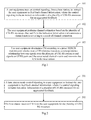
Fig.1 is a flow chart of a method for transmitting CSI at a user equipment according to an embodiment of the invention; -
Fig.2 is a flow chart of a method for transmitting CSI at a base station according to an embodiment of the invention; -
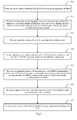
Fig.3 is a flow chart of a method for transmitting CSI at a user equipment and a base station according to an embodiment of the invention; -
Fig.4 is a structural diagram of a user equipment according to an embodiment of the invention; and -
Fig.5 is a structural diagram of a base station according to an embodiment of the invention. - In an embodiment of the invention, initially it is assumed that PMI and RI feedbacks are configured, and a PDSCH or a UERS signal


- This embodiment can be applied to CoMP, so a CSI-RS resource corresponds to a point which is a physical point or a virtual point.
- Referring to
Fig.1 , a flow chart of transmitting CSI at a user equipment in this embodiment is as follows: - Step 101: A user equipment receives, from a base station, control signaling to instruct the user equipment to feed back channel information, where the control signaling includes indication information of a plurality of CSI-RS resources for an aggregated feedback. The control signaling can further include feedback mode indication information of the CSI feedback, etc.
- Step 102: The user equipment performs channel estimation based on the plurality of CSI-RS resources obtained from the indication information and constructs a channel matrix according to a result of channel estimation.
- Step 103: The user equipment determines CSI according to a preset PDSCH transmission scheme over a CSI reference resource, a correspondence relationship between signals over the plurality of CSI-RS resources and signals on UERS ports and the constructed channel matrix, and then the user equipment transmits the CSI to the base station at least for the base station to use the technology of CoMP over a UERS based PDSCH. Specifically the CSI includes a Rank Indication (RI), a Pre-coding Matrix Indicator (PMI) and a Channel Quality Indicator (CQI). An optimum pre-coding matrix is determined by the channel matrix to further determine the PMI, and the RI is determined by a rank corresponding to the determined pre-coding matrix, and the CQI is determined by the PMI and the RI.
- Specifically the CSI reference resource can be defined as:
- In the frequency domain, the CSI reference resource is consisted of a bandwidth corresponding to a set of downlink physical resource blocks and particularly determined by the feedback mode.
- In the time domain, the CSI reference resource is defined by a downlink sub-frame n- n CQI_ref, where n represents the sub-frame for the CSI reporting, and n CQI_ref is an integer and determined particularly as follows:
- For a periodic CSI feedback, n CQI_ref is the least value which is no less than 4 such that the CSI reference sub-frame is a valid downlink sub-frame;
- For an aperiodic CSI feedback triggered by a downlink control signaling for the uplink grant, n CQI_ref is the difference between the sub-frame containing the downlink control signaling and the subframe for CSI reporting; and
- For an aperiodic CSI feedback triggered by a random access response, n CQI_ref is 4 and n- n CQI_ref corresponds to a valid downlink sub-frame.
- In the layer domain, the CSI reference resource is determined by the RI and the PMI based upon which the CQI is calculated.
- Assumed that an overhead of a UERS is the same as that of a recently reported RI when PMI and RI feedbacks are configured, then a PDSCH or a UERS signal


- Following this assumption, the step in which the user equipment determines the CSI according to the constructed channel matrix includes: for the joint of the plurality of CSI-RS resources, the user equipment determines the pre-coding matrix according to the constructed channel matrix and determines the CSI according to the determined pre-coding matrix. This solution is primarily applicable to a scenario in which the transmission mode of a PDSCH is the Joint Transmission (JT) mode.
- Preferably assumed that an overhead of a UERS is the same as that of a recently reported RI when PMI and RI feedbacks are configured, and a PDSCH or a UERS signal


- Following this assumption, the step in which the user equipment determines the CSI according to the constructed channel matrix includes: the user equipment determines a pre-coding matrix according to the constructed channel matrix for each resource element over the plurality of CSI-RS resources, and determines the CSI according to the determined the pre-coding matrix. This solution is primarily applicable to a scenario in which the transmission mode of the PDSCH is the incoherent JT.
- Alternatively assumed that an overhead of a UERS is the same as that of a recently reported RI when PMI and RI feedbacks are configured, and a PDSCH or a UERS signal


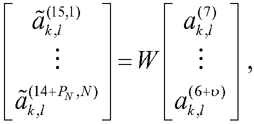


- Following this assumption, the step in which the user equipment determines the CSI according to the constructed channel matrix includes: the user equipment determines a pre-coding matrix according to the constructed channel matrix and the correlation information between the plurality of CSI-RS resources for each resource element over the plurality of CSI-RS resources, and determines the CSI according to the determined the pre-coding matrix. This solution is primarily applicable to a scenario in which the transmission mode of the PDSCH is coherent JT.
- In contrast to the user equipment side, the base station needs to transmit the control signaling to the user equipment to instruct the user equipment to feed back CSI for the plurality of CSI-RS resources. Reference can be made to the following embodiment for an implementation process thereof.
- Referring to
Fig.2 , a flow of a method for transmitting CSI at a base station in the embodiment is as follows: - Step 201: Abase station sends control signaling to a user equipment to instruct the user equipment to feed back channel information, where the control signaling includes indication information of a plurality of CSI-RS resources for an aggregated feedback.
- Step 202: The base station receives CSI from the user equipment for the plurality of CSI-RS resources.
- The CSI received, by the base station, from the user equipment for the plurality of CSI-RS resources is determined according to a preset PDSCH transmission scheme over a CSI reference resource, a correspondence relationship between signals over the plurality of CSI-RS resources and signals on UERS ports and a constructed channel matrix.
- The correspondence relationship is
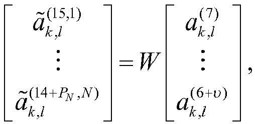


- If the total number of CSI-RS ports over the N CSI-RS resources is 1, then W is 1; otherwise, W represents a pre-coding matrix corresponding to a reported PMI applied on the (k, l) -th resource element.
- Preferably

- Alternatively

- The correlation information between the CSI-RS resources includes phase information and/or amplitude information.
- The implementation process of transmitting CSI has been introduced above respectively for the user equipment side and base station side, and an implementation process thereof at both of the sides will be introduced below.
- Referring to
Fig.3 , a flow of a method for transmitting CSI in this embodiment is as follows: - Step 301: Abase station determines a plurality of CSI-RS resources for an aggregated feedback.
- Step 302: The base station sends control signaling to a user equipment to instruct the user equipment to feed back channel information, where the control signaling includes indication information of the plurality of CSI-RS resources for an aggregated feedback and a feedback mode.
- Step 303: The user equipment receives the control signaling from the base station.
- Step 304: The user equipment constructs a channel matrix for CSI reference signals over the plurality of CSI-RS resources based upon the indication information.
- Step 305: The user equipment determines CSI according to a preset PDSCH transmission scheme over a CSI reference resource, a correspondence relationship between signals over the plurality of CSI-RS resources and signals on UERS ports and the constructed channel matrix.
- Step 306: The user equipment feeds back the CSI to the base station in the feedback mode indicated by the control signaling.
- The step 307: The base station receives the CSI and schedules the user equipment according to the CSI.
- The implementation process of transmitting CSI at the user equipment and the base station has been described, and internal structures of the user equipment and the base station will be introduced below.
- Referring to
Fig.4 , a user equipment in this embodiment includes aninterface module 401, achannel estimation module 402 and aCSI determination module 403. - The
interface module 401 is configured to receive control signaling, from a base station, to instruct the user equipment to feed back channel information, where the control signaling includes indication information of a plurality of CSI-RS resources for an aggregated feedback. - The
channel estimation module 402 is configured to perform channel estimation based on the plurality of CSI-RS resources obtained from the indication information and to construct a channel matrix according to a result of channel estimation. - The
CSI determination module 403 is configured to determine CSI according to a preset PDSCH transmission scheme over a CSI reference resource, a correspondence relationship between signals over the plurality of CSI-RS resources and signals on UERS ports and the constructed channel matrix, and to instruct the interface module to transmit the CSI to the base station. - The
CSI determination module 403 is configured to determine a pre-coding matrix according to the preset PDSCH transmission scheme over the CSI reference resource, the correspondence relationship


- If the total number of CSI-RS ports over the N CSI-RS resources is 1, then W is 1; otherwise, W represents a pre-coding matrix corresponding to a reported PMI applied on the (k, /) -th resource element.
- Preferably

- Alternatively

- Where the correlation information between the CSI-RS resources includes phase information and/or amplitude information.
- Referring to
Fig.5 , a base station in this embodiment includes a sendingmodule 501 and areception module 502. - The sending
module 501 is configured to send control signaling to a user equipment to instruct the user equipment to feed back channel information, where the control signaling includes indication information of a plurality of CSI-RS resources for an aggregated feedback; and - The
reception module 502 is configured to receive CSI from the user equipment for the plurality of CSI-RS resources. - The CSI received, by the
reception module 502, from the user equipment for the plurality of CSI-RS resources is determined according to a preset PDSCH transmission scheme over a CSI reference resource, a correspondence relationship between signals over the plurality of CSI-RS resources and signals on UERS ports and a constructed channel matrix. - The correspondence relationship is


- If the total number of CSI-RS ports over the N CSI-RS resources is 1, then W is 1; otherwise, W represents a pre-coding matrix corresponding to a reported PMI applied on the (k, /) -th resource element.
- Preferably

- Alternatively

- The correlation information between the CSI-RS resources includes phase information and/or amplitude information.
- In the embodiment of the invention, initially assumed that PMI and RI feedbacks are configured, and a PDSCH or a UERS signal


- Those skilled in the art shall appreciate that the embodiments of the invention can be embodied as a method, a system or a computer program product. Therefore the invention can be embodied in the form of an all-hardware embodiment, an all-software embodiment or an embodiment of software and hardware in combination. Furthermore the invention can be embodied in the form of a computer program product embodied in one or more computer useable storage mediums (including but not limited to a disk memory, an optical memory, etc.) in which computer useable program codes are contained.
- The invention has been described in a flow chart and/or a block diagram of the method, the device (system) and the computer program product according to the embodiments of the invention. It shall be appreciated that respective flows and/or blocks in the flow chart and/or the block diagram and combinations of the flows and/or the blocks in the flow chart and/or the block diagram can be embodied in computer program instructions. These computer program instructions can be loaded onto a general-purpose computer, a specific-purpose computer, an embedded processor or a processor of another programmable data processing device to produce a machine so that the instructions executed on the computer or the processor of the other programmable data processing device create means for performing the functions specified in the flow(s) of the flow chart and/or the block(s) of the block diagram.
- These computer program instructions can also be stored into a computer readable memory capable of directing the computer or the other programmable data processing device to operate in a specific manner so that the instructions stored in the computer readable memory create an article of manufacture including instruction means which perform the functions specified in the flow(s) of the flow chart and/or the block(s) of the block diagram.
- These computer program instructions can also be loaded onto the computer or the other programmable data processing device so that a series of operational steps are performed on the computer or the other programmable data processing device to create a computer implemented process so that the instructions executed on the computer or the other programmable device provide steps for performing the functions specified in the flow(s) of the flow chart and/or the block(s) of the block diagram.
- Evidently those skilled in the art can make various modifications and variations to the invention without departing from the spirit and scope of the invention. Thus the invention is also intended to encompass these modifications and variations thereto so long as the modifications and variations come into the scope of the claims appended to the invention and their equivalents.
Claims (26)
- A method for transmitting Channel State Information, CSI, comprising:receiving, by a user equipment, control signaling, from a base station, to instruct the user equipment to feed back channel information, wherein the control signaling includes indication information of a plurality of Channel State Information-Reference Signal, CSI-RS, resources for an aggregated feedback;performing, by the user equipment, channel estimation based on the plurality of CSI-RS resources obtained from the indication information and constructing a channel matrix according to a result of channel estimation; anddetermining, by the user equipment, CSI according to a preset Physical Downlink Shared Channel, PDSCH, transmission scheme over a CSI reference resource, a correspondence relationship between signals over the plurality of CSI-RS resources and signals on UERS ports and the constructed channel matrix, and transmitting the CSI to the base station.
- The method according to claim 1, wherein determining by the user equipment the CSI according to the preset PDSCH transmission scheme over the CSI reference resource, the correspondence relationship between signals over the plurality of CSI-RS resources and signals on UERS ports and the constructed channel matrix comprises:determining, by the user equipment, a pre-coding matrix according to the preset PDSCH transmission scheme over the CSI reference resource, the correspondence relationship


- The method according to claim 2, wherein if the total number of CSI-RS ports over the N CSI-RS resources is 1, then W is 1; otherwise, W represents a pre-coding matrix corresponding to a reported Pre-coding Matrix Indicator, PMI, applied on the (k, l) -th resource element.
- The method according to claim 2, wherein

- The method according to claim 2, wherein

- The method according to claim 5, wherein the correlation information between the CSI-RS resources comprises phase information and/or amplitude information.
- A method for transmitting CSI, comprising the steps of:sending, by a base station, control signaling to a user equipment to instruct the user equipment to feed back channel information, wherein the control signaling includes indication information of a plurality of CSI-RS resources for an aggregated feedback; andreceiving, by the base station, CSI from the user equipment for the plurality of CSI-RS resources.
- The method according to claim 7, wherein the CSI received, by the base station, from the user equipment for the plurality of CSI-RS resources is determined according to a preset PDSCH transmission scheme over a CSI reference resource, a correspondence relationship between signals over the plurality of CSI-RS resources and signals on UERS ports and a constructed channel matrix.
- The method according to claim 8, wherein the correspondence relationship is


- The method according to claim 9, wherein if the total number of CSI-RS ports over the N CSI-RS resources is 1, then W is 1; otherwise, W represents a pre-coding matrix corresponding to a reported PMI applied on the (k, l) -th resource element.
- The method according to claim 9, wherein

- The method according to claim 9, wherein

- The method according to claim 12, wherein the correlation information between the CSI-RS resources comprises phase information and/or amplitude information.
- A user equipment, comprising:an interface module configured to receive control signaling, from a base station, to instruct the user equipment to feed back channel information, wherein the control signaling includes indication information of a plurality of CSI-RS resources for an aggregated feedback;a channel estimation module configured to perform channel estimation based on the plurality of CSI-RS resources obtained from the indication information and to construct a channel matrix according to a result of channel estimation;a CSI determination module configured to determine CSI according to a preset Physical Downlink Shared Channel, PDSCH, transmission scheme over a CSI reference resource, a correspondence relationship between signals over the plurality of CSI-RS resources and signals on UERS ports and the constructed channel matrix, and to instruct the interface module to transmit the CSI to the base station.
- The user equipment according to claim 14, wherein the CSI determination module is configured to determine a pre-coding matrix according to the preset PDSCH transmission scheme over the CSI reference resource, the correspondence relationship


- The user equipment according to claim 15, wherein if the total number of CSI-RS ports over the N CSI-RS resources is 1, then W is 1; otherwise, W represents a pre-coding matrix corresponding to a reported PMI applied on the (k, l) -th resource element.
- The user equipment according to claim 15, wherein

- The user equipment according to claim 15, wherein

- The user equipment according to claim 18, wherein the correlation information between the CSI-RS resources comprises phase information and/or amplitude information.
- Abase station, comprising:a sending module configured to send control signaling to a user equipment to instruct the user equipment to feed back channel information, wherein the control signaling includes indication information of a plurality of CSI-RS resources for an aggregated feedback; anda reception module configured to receive CSI from the user equipment for the plurality of CSI-RS resources.
- The base station according to claim 20, wherein the CSI received, by the reception module, from the user equipment for the plurality of CSI-RS resources is determined according to a preset PDSCH transmission scheme over a CSI reference resource, a correspondence relationship between signals over the plurality of CSI-RS resources and signals on UERS ports and a constructed channel matrix.
- The base station according to claim 21, wherein the correspondence relationship is


- The base station according to claim 22, wherein if the total number of CSI-RS ports over the N CSI-RS resources is 1, then W is 1; otherwise, W represents a pre-coding matrix corresponding to a reported PMI applied on the (k, /) -th resource element.
- The base station according to claim 22, wherein

- The base station according to claim 22, wherein

- The base station according to claim 25, wherein the correlation information between the CSI-RS resources comprises phase information and/or amplitude information.
Applications Claiming Priority (2)
| Application Number | Priority Date | Filing Date | Title |
|---|---|---|---|
| CN2011104604238A CN102546110A (en) | 2011-12-31 | 2011-12-31 | Channel state information transmission method and device |
| PCT/CN2012/081925 WO2013097502A1 (en) | 2011-12-31 | 2012-09-25 | Method and device for transmitting channel state information |
Publications (3)
| Publication Number | Publication Date |
|---|---|
| EP2800290A1 true EP2800290A1 (en) | 2014-11-05 |
| EP2800290A4 EP2800290A4 (en) | 2014-11-19 |
| EP2800290B1 EP2800290B1 (en) | 2015-11-18 |
Family
ID=46352137
Family Applications (1)
| Application Number | Title | Priority Date | Filing Date |
|---|---|---|---|
| EP12863608.1A Active EP2800290B1 (en) | 2011-12-31 | 2012-09-25 | Method and device for processing channel state information |
Country Status (4)
| Country | Link |
|---|---|
| US (1) | US9503243B2 (en) |
| EP (1) | EP2800290B1 (en) |
| CN (1) | CN102546110A (en) |
| WO (2) | WO2013097500A1 (en) |
Cited By (3)
| Publication number | Priority date | Publication date | Assignee | Title |
|---|---|---|---|---|
| CN107623561A (en) * | 2016-07-13 | 2018-01-23 | 中国移动通信有限公司研究院 | A kind of information transmission method and base station |
| CN110495127A (en) * | 2017-02-06 | 2019-11-22 | 瑞典爱立信有限公司 | Dynamic Indication for Channel State Information Feedback |
| EP3537620A4 (en) * | 2016-11-04 | 2020-04-29 | ZTE Corporation | CHANNEL INFORMATION QUANTIFICATION FEEDBACK METHOD AND APPARATUS, ELECTRONIC DEVICE AND INFORMATION MEDIUM |
Families Citing this family (38)
| Publication number | Priority date | Publication date | Assignee | Title |
|---|---|---|---|---|
| CN102546110A (en) * | 2011-12-31 | 2012-07-04 | 电信科学技术研究院 | Channel state information transmission method and device |
| WO2014019173A1 (en) * | 2012-08-01 | 2014-02-06 | 富士通株式会社 | Method and apparatus for determining channel state information reference resource |
| EP2880892A4 (en) * | 2012-08-03 | 2016-03-23 | Nokia Solutions & Networks Oy | Method and apparatus |
| US8976698B2 (en) * | 2012-08-09 | 2015-03-10 | Qualcomm Incorporated | Methods and apparatus for radio link monitoring in new carrier type (NCT) in a long term evolution (LTE) system |
| WO2014047797A1 (en) | 2012-09-26 | 2014-04-03 | 华为技术有限公司 | Channel state information measurement method, device and system |
| CN103905161A (en) * | 2012-12-26 | 2014-07-02 | 中兴通讯股份有限公司 | Precoding matrix selection method and device |
| CN104038319B (en) | 2013-03-04 | 2018-12-21 | 夏普株式会社 | The information feedback and user equipment of multiple exit point partner systems |
| CN104303445B (en) * | 2013-05-14 | 2017-12-22 | 华为技术有限公司 | The CSI feedback method and user equipment of the Physical Downlink Control Channel of enhancing |
| US9768924B2 (en) * | 2013-08-14 | 2017-09-19 | Hewlett Packard Enterprise Development Lp | Transmit antenna selection |
| RU2627739C1 (en) * | 2013-09-11 | 2017-08-11 | Хуавей Текнолоджиз Ко., Лтд. | Method of configuring signal information on state of channel and basic station |
| WO2015168925A1 (en) | 2014-05-09 | 2015-11-12 | Qualcomm Incorporated | Restricted aperiodic csi measurement reporting in enhanced interference management and traffic adaptation |
| CN105322995B (en) * | 2014-07-30 | 2019-04-02 | 电信科学技术研究院 | Pilot sending method, channel measuring method and device in mimo system |
| WO2016086971A1 (en) * | 2014-12-02 | 2016-06-09 | Nokia Solutions And Networks Management International Gmbh | Coded allocation of channel state information reference signals |
| CN106162887B (en) * | 2015-04-09 | 2019-09-17 | 北京邮电大学 | A kind of matched method and system of resource-sharing |
| US10554280B2 (en) * | 2015-05-01 | 2020-02-04 | Futurewei Technologies, Inc. | Device, network, and method for CSI feedback of hybrid beamforming |
| WO2017075803A1 (en) | 2015-11-06 | 2017-05-11 | Qualcomm Incorporated | Csi feedback processing and reporting for eb/fd-mimo |
| CN107204794B (en) | 2016-03-18 | 2020-02-21 | 电信科学技术研究院 | A CSI feedback method and device |
| CN107294578B (en) * | 2016-04-01 | 2021-01-29 | 华为技术有限公司 | Data transmission method and device |
| CN107370582A (en) * | 2016-05-12 | 2017-11-21 | 株式会社Ntt都科摩 | reference signal sending method, detection method, base station and mobile station |
| WO2017193331A1 (en) * | 2016-05-12 | 2017-11-16 | Qualcomm Incorporated | Hybrid class b fd-mimo |
| WO2018058559A1 (en) | 2016-09-30 | 2018-04-05 | Qualcomm Incorporated | Channel state information (csi) acquisition for dynamic mimo transmission |
| GB2558217B (en) * | 2016-12-22 | 2020-08-19 | Samsung Electronics Co Ltd | Using feedback from user equipment to determine mode of joint transmission |
| CN110233655B (en) * | 2017-01-06 | 2020-10-27 | 华为技术有限公司 | A signal transmission method, network device and terminal device |
| CN115664476B (en) * | 2017-02-06 | 2024-09-27 | 中兴通讯股份有限公司 | A channel information feedback and receiving method and device |
| CN109391404B (en) * | 2017-08-10 | 2021-02-09 | 电信科学技术研究院有限公司 | CSI feedback and control method and device thereof |
| CN108039903B (en) * | 2017-09-11 | 2021-06-01 | 华为技术有限公司 | A communication method and device |
| CN110190941B (en) | 2018-01-12 | 2022-05-10 | 华为技术有限公司 | Method, device and system for transmitting terminal equipment capacity |
| CN110138527B (en) * | 2018-02-09 | 2022-05-27 | 大唐移动通信设备有限公司 | Resource indicating and determining method and device |
| CN112840587B (en) * | 2018-08-10 | 2024-07-05 | 高通股份有限公司 | Quasi-co-location indication of non-zero power channel state information reference signal port group |
| CN111294101B (en) | 2018-12-10 | 2022-02-25 | 华为技术有限公司 | CSI measuring method and device |
| CN109450605B (en) * | 2018-12-26 | 2022-08-19 | 杭州铭智云教育科技有限公司 | High-safety scheduling method based on double-measurement-method feedback |
| US20210143878A1 (en) * | 2019-11-08 | 2021-05-13 | Huawei Technologies Co., Ltd. | Method and apparatus for channel state information feedback for joint transmission |
| EP4128560B1 (en) * | 2020-03-31 | 2024-11-13 | Telefonaktiebolaget LM Ericsson (publ.) | Channel quality indication (cqi) saturation mitigation |
| CN115486171B (en) * | 2020-05-15 | 2025-01-07 | 中兴通讯股份有限公司 | Methods used to report configuration |
| CN113746573B (en) * | 2020-05-30 | 2023-01-06 | 华为技术有限公司 | Channel measurement method and device |
| US12088378B2 (en) * | 2020-09-18 | 2024-09-10 | Qualcomm Incorporated | Low overhead and high accuracy channel state feedback using neural networks |
| CN116032416A (en) * | 2021-10-25 | 2023-04-28 | 维沃软件技术有限公司 | Channel state information reporting method, device, terminal and network side equipment |
| US12526027B2 (en) * | 2023-06-14 | 2026-01-13 | Qualcomm Incorporated | Network node antenna grouping for power reduction on ue |
Family Cites Families (15)
| Publication number | Priority date | Publication date | Assignee | Title |
|---|---|---|---|---|
| WO2010101431A2 (en) * | 2009-03-04 | 2010-09-10 | Lg Electronics Inc. | Method for performing comp operation and transmitting feedback information in a wireless communication system |
| KR101754970B1 (en) * | 2010-01-12 | 2017-07-06 | 삼성전자주식회사 | DEVICE AND METHOD FOR COMMUNCATING CSI-RS(Channel State Information reference signal) IN WIRELESS COMMUNICATION SYSTEM |
| US9407409B2 (en) | 2010-02-23 | 2016-08-02 | Qualcomm Incorporated | Channel state information reference signals |
| JP5396306B2 (en) * | 2010-02-24 | 2014-01-22 | 株式会社Nttドコモ | Precoding weight generation method and control apparatus |
| CN102045762B (en) * | 2010-12-02 | 2013-07-24 | 大唐移动通信设备有限公司 | Method and device for reporting channel state |
| CN102111246B (en) * | 2011-01-12 | 2017-03-29 | 中兴通讯股份有限公司 | The method and user equipment of feeding back channel state information |
| CN102843209B (en) * | 2011-06-22 | 2015-09-30 | 华为技术有限公司 | The method and apparatus of control channel |
| CN102255689B (en) * | 2011-07-08 | 2018-05-04 | 中兴通讯股份有限公司 | A kind of processing method of channel condition information, apparatus and system |
| CN102256358B (en) * | 2011-07-08 | 2013-11-20 | 电信科学技术研究院 | Data transmission and receiving method, device and system |
| CN102291212B (en) * | 2011-08-12 | 2014-06-18 | 电信科学技术研究院 | Feedback method and device of channel state information |
| CN102291839B (en) | 2011-08-16 | 2014-07-09 | 电信科学技术研究院 | Method and device for transmitting CQI (channel quality indicator) information |
| WO2013062386A1 (en) * | 2011-10-27 | 2013-05-02 | 엘지전자 주식회사 | Method and apparatus for feeding back aggregated channel state information in cooperative multipoint communication system |
| GB2493224B (en) * | 2011-11-07 | 2013-07-03 | Renesas Mobile Corp | Wireless communication network |
| CN103188827A (en) * | 2011-12-29 | 2013-07-03 | 夏普株式会社 | Channel state information feedback method and user equipment in multiple base station cooperation process |
| CN102546110A (en) * | 2011-12-31 | 2012-07-04 | 电信科学技术研究院 | Channel state information transmission method and device |
-
2011
- 2011-12-31 CN CN2011104604238A patent/CN102546110A/en active Pending
-
2012
- 2012-09-25 WO PCT/CN2012/081914 patent/WO2013097500A1/en not_active Ceased
- 2012-09-25 US US14/370,033 patent/US9503243B2/en active Active
- 2012-09-25 WO PCT/CN2012/081925 patent/WO2013097502A1/en not_active Ceased
- 2012-09-25 EP EP12863608.1A patent/EP2800290B1/en active Active
Cited By (5)
| Publication number | Priority date | Publication date | Assignee | Title |
|---|---|---|---|---|
| CN107623561A (en) * | 2016-07-13 | 2018-01-23 | 中国移动通信有限公司研究院 | A kind of information transmission method and base station |
| CN107623561B (en) * | 2016-07-13 | 2020-01-07 | 中国移动通信有限公司研究院 | Information transmission method and base station |
| EP3537620A4 (en) * | 2016-11-04 | 2020-04-29 | ZTE Corporation | CHANNEL INFORMATION QUANTIFICATION FEEDBACK METHOD AND APPARATUS, ELECTRONIC DEVICE AND INFORMATION MEDIUM |
| CN110495127A (en) * | 2017-02-06 | 2019-11-22 | 瑞典爱立信有限公司 | Dynamic Indication for Channel State Information Feedback |
| US11825325B2 (en) | 2017-02-06 | 2023-11-21 | Telefonaktiebolaget Lm Ericsson (Publ) | Dynamic indication for channel state information feedback |
Also Published As
| Publication number | Publication date |
|---|---|
| CN102546110A (en) | 2012-07-04 |
| EP2800290B1 (en) | 2015-11-18 |
| US9503243B2 (en) | 2016-11-22 |
| WO2013097502A1 (en) | 2013-07-04 |
| US20140369291A1 (en) | 2014-12-18 |
| EP2800290A4 (en) | 2014-11-19 |
| WO2013097500A1 (en) | 2013-07-04 |
Similar Documents
| Publication | Publication Date | Title |
|---|---|---|
| EP2800290B1 (en) | Method and device for processing channel state information | |
| US11705950B2 (en) | Method and apparatus for resource-based CSI acquisition in advanced wireless communication systems | |
| US11044065B2 (en) | Method and apparatus for transmitting and receiving feedback information in mobile communication system using multiple antennas | |
| EP2701425B1 (en) | Method, device, and system for reporting channel quality indicator | |
| EP2701423B1 (en) | Method and device for measuring interference in coordinated multipoint transmission | |
| JP6410054B2 (en) | Feedback method and apparatus in mobile communication system | |
| EP2648445B1 (en) | Method and device for reporting channel state | |
| US11956765B2 (en) | UE RX beam switching during UE beam training | |
| US9655109B2 (en) | Channel state information reference resource indication and measurement method and device | |
| EP3104541A1 (en) | Csi reporting for a set of csi-rs resources | |
| CN102474408B (en) | Method for operating a radio station in a mobile network | |
| CN108111199A (en) | Channel state information feedback, receiving method and device, equipment, storage medium | |
| AU2016241468A2 (en) | Resource allocation device and method in large-scale antenna system | |
| US9363064B2 (en) | Comp transmission feedback method, device and system | |
| KR20180129875A (en) | Method and apparatus for enabling uplink MIMO | |
| US9615280B2 (en) | Calculating and reporting channel characteristics | |
| WO2013020445A1 (en) | Method, system and device for configuring and reporting measurement information | |
| CN102291229A (en) | Channel state information feedback method, receiving method and equipment |
Legal Events
| Date | Code | Title | Description |
|---|---|---|---|
| PUAI | Public reference made under article 153(3) epc to a published international application that has entered the european phase |
Free format text: ORIGINAL CODE: 0009012 |
|
| 17P | Request for examination filed |
Effective date: 20140626 |
|
| AK | Designated contracting states |
Kind code of ref document: A1 Designated state(s): AL AT BE BG CH CY CZ DE DK EE ES FI FR GB GR HR HU IE IS IT LI LT LU LV MC MK MT NL NO PL PT RO RS SE SI SK SM TR |
|
| A4 | Supplementary search report drawn up and despatched |
Effective date: 20141020 |
|
| RIC1 | Information provided on ipc code assigned before grant |
Ipc: H04L 5/00 20060101ALI20141014BHEP Ipc: H04B 7/02 20060101ALI20141014BHEP Ipc: H04B 7/06 20060101ALI20141014BHEP Ipc: H04L 1/00 20060101AFI20141014BHEP |
|
| DAX | Request for extension of the european patent (deleted) | ||
| GRAP | Despatch of communication of intention to grant a patent |
Free format text: ORIGINAL CODE: EPIDOSNIGR1 |
|
| INTG | Intention to grant announced |
Effective date: 20150617 |
|
| GRAS | Grant fee paid |
Free format text: ORIGINAL CODE: EPIDOSNIGR3 |
|
| GRAA | (expected) grant |
Free format text: ORIGINAL CODE: 0009210 |
|
| AK | Designated contracting states |
Kind code of ref document: B1 Designated state(s): AL AT BE BG CH CY CZ DE DK EE ES FI FR GB GR HR HU IE IS IT LI LT LU LV MC MK MT NL NO PL PT RO RS SE SI SK SM TR |
|
| REG | Reference to a national code |
Ref country code: GB Ref legal event code: FG4D |
|
| REG | Reference to a national code |
Ref country code: CH Ref legal event code: EP |
|
| REG | Reference to a national code |
Ref country code: AT Ref legal event code: REF Ref document number: 762005 Country of ref document: AT Kind code of ref document: T Effective date: 20151215 |
|
| REG | Reference to a national code |
Ref country code: IE Ref legal event code: FG4D |
|
| REG | Reference to a national code |
Ref country code: DE Ref legal event code: R096 Ref document number: 602012012529 Country of ref document: DE |
|
| REG | Reference to a national code |
Ref country code: NL Ref legal event code: MP Effective date: 20160218 |
|
| REG | Reference to a national code |
Ref country code: LT Ref legal event code: MG4D |
|
| REG | Reference to a national code |
Ref country code: AT Ref legal event code: MK05 Ref document number: 762005 Country of ref document: AT Kind code of ref document: T Effective date: 20151118 |
|
| PG25 | Lapsed in a contracting state [announced via postgrant information from national office to epo] |
Ref country code: HR Free format text: LAPSE BECAUSE OF FAILURE TO SUBMIT A TRANSLATION OF THE DESCRIPTION OR TO PAY THE FEE WITHIN THE PRESCRIBED TIME-LIMIT Effective date: 20151118 Ref country code: IT Free format text: LAPSE BECAUSE OF FAILURE TO SUBMIT A TRANSLATION OF THE DESCRIPTION OR TO PAY THE FEE WITHIN THE PRESCRIBED TIME-LIMIT Effective date: 20151118 Ref country code: IS Free format text: LAPSE BECAUSE OF FAILURE TO SUBMIT A TRANSLATION OF THE DESCRIPTION OR TO PAY THE FEE WITHIN THE PRESCRIBED TIME-LIMIT Effective date: 20160318 Ref country code: NL Free format text: LAPSE BECAUSE OF FAILURE TO SUBMIT A TRANSLATION OF THE DESCRIPTION OR TO PAY THE FEE WITHIN THE PRESCRIBED TIME-LIMIT Effective date: 20151118 Ref country code: LT Free format text: LAPSE BECAUSE OF FAILURE TO SUBMIT A TRANSLATION OF THE DESCRIPTION OR TO PAY THE FEE WITHIN THE PRESCRIBED TIME-LIMIT Effective date: 20151118 Ref country code: ES Free format text: LAPSE BECAUSE OF FAILURE TO SUBMIT A TRANSLATION OF THE DESCRIPTION OR TO PAY THE FEE WITHIN THE PRESCRIBED TIME-LIMIT Effective date: 20151118 Ref country code: NO Free format text: LAPSE BECAUSE OF FAILURE TO SUBMIT A TRANSLATION OF THE DESCRIPTION OR TO PAY THE FEE WITHIN THE PRESCRIBED TIME-LIMIT Effective date: 20160218 |
|
| PG25 | Lapsed in a contracting state [announced via postgrant information from national office to epo] |
Ref country code: FI Free format text: LAPSE BECAUSE OF FAILURE TO SUBMIT A TRANSLATION OF THE DESCRIPTION OR TO PAY THE FEE WITHIN THE PRESCRIBED TIME-LIMIT Effective date: 20151118 Ref country code: PL Free format text: LAPSE BECAUSE OF FAILURE TO SUBMIT A TRANSLATION OF THE DESCRIPTION OR TO PAY THE FEE WITHIN THE PRESCRIBED TIME-LIMIT Effective date: 20151118 Ref country code: PT Free format text: LAPSE BECAUSE OF FAILURE TO SUBMIT A TRANSLATION OF THE DESCRIPTION OR TO PAY THE FEE WITHIN THE PRESCRIBED TIME-LIMIT Effective date: 20160318 Ref country code: RS Free format text: LAPSE BECAUSE OF FAILURE TO SUBMIT A TRANSLATION OF THE DESCRIPTION OR TO PAY THE FEE WITHIN THE PRESCRIBED TIME-LIMIT Effective date: 20151118 Ref country code: SE Free format text: LAPSE BECAUSE OF FAILURE TO SUBMIT A TRANSLATION OF THE DESCRIPTION OR TO PAY THE FEE WITHIN THE PRESCRIBED TIME-LIMIT Effective date: 20151118 Ref country code: AT Free format text: LAPSE BECAUSE OF FAILURE TO SUBMIT A TRANSLATION OF THE DESCRIPTION OR TO PAY THE FEE WITHIN THE PRESCRIBED TIME-LIMIT Effective date: 20151118 Ref country code: GR Free format text: LAPSE BECAUSE OF FAILURE TO SUBMIT A TRANSLATION OF THE DESCRIPTION OR TO PAY THE FEE WITHIN THE PRESCRIBED TIME-LIMIT Effective date: 20160219 Ref country code: LV Free format text: LAPSE BECAUSE OF FAILURE TO SUBMIT A TRANSLATION OF THE DESCRIPTION OR TO PAY THE FEE WITHIN THE PRESCRIBED TIME-LIMIT Effective date: 20151118 |
|
| PG25 | Lapsed in a contracting state [announced via postgrant information from national office to epo] |
Ref country code: CZ Free format text: LAPSE BECAUSE OF FAILURE TO SUBMIT A TRANSLATION OF THE DESCRIPTION OR TO PAY THE FEE WITHIN THE PRESCRIBED TIME-LIMIT Effective date: 20151118 |
|
| REG | Reference to a national code |
Ref country code: DE Ref legal event code: R097 Ref document number: 602012012529 Country of ref document: DE |
|
| PG25 | Lapsed in a contracting state [announced via postgrant information from national office to epo] |
Ref country code: SM Free format text: LAPSE BECAUSE OF FAILURE TO SUBMIT A TRANSLATION OF THE DESCRIPTION OR TO PAY THE FEE WITHIN THE PRESCRIBED TIME-LIMIT Effective date: 20151118 Ref country code: DK Free format text: LAPSE BECAUSE OF FAILURE TO SUBMIT A TRANSLATION OF THE DESCRIPTION OR TO PAY THE FEE WITHIN THE PRESCRIBED TIME-LIMIT Effective date: 20151118 Ref country code: EE Free format text: LAPSE BECAUSE OF FAILURE TO SUBMIT A TRANSLATION OF THE DESCRIPTION OR TO PAY THE FEE WITHIN THE PRESCRIBED TIME-LIMIT Effective date: 20151118 Ref country code: RO Free format text: LAPSE BECAUSE OF FAILURE TO SUBMIT A TRANSLATION OF THE DESCRIPTION OR TO PAY THE FEE WITHIN THE PRESCRIBED TIME-LIMIT Effective date: 20151118 Ref country code: SK Free format text: LAPSE BECAUSE OF FAILURE TO SUBMIT A TRANSLATION OF THE DESCRIPTION OR TO PAY THE FEE WITHIN THE PRESCRIBED TIME-LIMIT Effective date: 20151118 |
|
| PLBE | No opposition filed within time limit |
Free format text: ORIGINAL CODE: 0009261 |
|
| STAA | Information on the status of an ep patent application or granted ep patent |
Free format text: STATUS: NO OPPOSITION FILED WITHIN TIME LIMIT |
|
| REG | Reference to a national code |
Ref country code: FR Ref legal event code: PLFP Year of fee payment: 5 |
|
| 26N | No opposition filed |
Effective date: 20160819 |
|
| PG25 | Lapsed in a contracting state [announced via postgrant information from national office to epo] |
Ref country code: SI Free format text: LAPSE BECAUSE OF FAILURE TO SUBMIT A TRANSLATION OF THE DESCRIPTION OR TO PAY THE FEE WITHIN THE PRESCRIBED TIME-LIMIT Effective date: 20151118 |
|
| PG25 | Lapsed in a contracting state [announced via postgrant information from national office to epo] |
Ref country code: MC Free format text: LAPSE BECAUSE OF FAILURE TO SUBMIT A TRANSLATION OF THE DESCRIPTION OR TO PAY THE FEE WITHIN THE PRESCRIBED TIME-LIMIT Effective date: 20151118 |
|
| REG | Reference to a national code |
Ref country code: CH Ref legal event code: PL |
|
| REG | Reference to a national code |
Ref country code: IE Ref legal event code: MM4A |
|
| PG25 | Lapsed in a contracting state [announced via postgrant information from national office to epo] |
Ref country code: CH Free format text: LAPSE BECAUSE OF NON-PAYMENT OF DUE FEES Effective date: 20160930 Ref country code: LI Free format text: LAPSE BECAUSE OF NON-PAYMENT OF DUE FEES Effective date: 20160930 Ref country code: IE Free format text: LAPSE BECAUSE OF NON-PAYMENT OF DUE FEES Effective date: 20160925 |
|
| PG25 | Lapsed in a contracting state [announced via postgrant information from national office to epo] |
Ref country code: LU Free format text: LAPSE BECAUSE OF NON-PAYMENT OF DUE FEES Effective date: 20160925 |
|
| REG | Reference to a national code |
Ref country code: FR Ref legal event code: PLFP Year of fee payment: 6 |
|
| PG25 | Lapsed in a contracting state [announced via postgrant information from national office to epo] |
Ref country code: HU Free format text: LAPSE BECAUSE OF FAILURE TO SUBMIT A TRANSLATION OF THE DESCRIPTION OR TO PAY THE FEE WITHIN THE PRESCRIBED TIME-LIMIT; INVALID AB INITIO Effective date: 20120925 |
|
| PG25 | Lapsed in a contracting state [announced via postgrant information from national office to epo] |
Ref country code: MT Free format text: LAPSE BECAUSE OF NON-PAYMENT OF DUE FEES Effective date: 20160930 Ref country code: CY Free format text: LAPSE BECAUSE OF FAILURE TO SUBMIT A TRANSLATION OF THE DESCRIPTION OR TO PAY THE FEE WITHIN THE PRESCRIBED TIME-LIMIT Effective date: 20151118 Ref country code: MK Free format text: LAPSE BECAUSE OF FAILURE TO SUBMIT A TRANSLATION OF THE DESCRIPTION OR TO PAY THE FEE WITHIN THE PRESCRIBED TIME-LIMIT Effective date: 20151118 |
|
| PG25 | Lapsed in a contracting state [announced via postgrant information from national office to epo] |
Ref country code: BG Free format text: LAPSE BECAUSE OF FAILURE TO SUBMIT A TRANSLATION OF THE DESCRIPTION OR TO PAY THE FEE WITHIN THE PRESCRIBED TIME-LIMIT Effective date: 20151118 |
|
| REG | Reference to a national code |
Ref country code: FR Ref legal event code: PLFP Year of fee payment: 7 |
|
| PG25 | Lapsed in a contracting state [announced via postgrant information from national office to epo] |
Ref country code: TR Free format text: LAPSE BECAUSE OF FAILURE TO SUBMIT A TRANSLATION OF THE DESCRIPTION OR TO PAY THE FEE WITHIN THE PRESCRIBED TIME-LIMIT Effective date: 20151118 Ref country code: AL Free format text: LAPSE BECAUSE OF FAILURE TO SUBMIT A TRANSLATION OF THE DESCRIPTION OR TO PAY THE FEE WITHIN THE PRESCRIBED TIME-LIMIT Effective date: 20151118 |
|
| REG | Reference to a national code |
Ref country code: DE Ref legal event code: R081 Ref document number: 602012012529 Country of ref document: DE Owner name: DATANG MOBILE COMMUNICATIONS EQUIPMENT CO., LT, CN Free format text: FORMER OWNER: CHINA ACADEMY OF TELECOMMUNICATIONS TECHNOLOGY, BEIJING, CN |
|
| REG | Reference to a national code |
Ref country code: BE Ref legal event code: PD Owner name: DATANG MOBILE COMMUNICATIONS EQUIPMENT CO., LTD.; CN Free format text: DETAILS ASSIGNMENT: CHANGE OF OWNER(S), ASSIGNMENT; FORMER OWNER NAME: CHINA ACADEMY OF TELECOMMUNICATIONS TECHNOLOGY Effective date: 20210816 |
|
| REG | Reference to a national code |
Ref country code: GB Ref legal event code: 732E Free format text: REGISTERED BETWEEN 20211007 AND 20211013 |
|
| P01 | Opt-out of the competence of the unified patent court (upc) registered |
Effective date: 20230512 |
|
| PGFP | Annual fee paid to national office [announced via postgrant information from national office to epo] |
Ref country code: DE Payment date: 20250919 Year of fee payment: 14 |
|
| PGFP | Annual fee paid to national office [announced via postgrant information from national office to epo] |
Ref country code: BE Payment date: 20250918 Year of fee payment: 14 Ref country code: GB Payment date: 20250918 Year of fee payment: 14 |
|
| PGFP | Annual fee paid to national office [announced via postgrant information from national office to epo] |
Ref country code: FR Payment date: 20250922 Year of fee payment: 14 |