EP2800249A1 - Motor - Google Patents
Motor Download PDFInfo
- Publication number
- EP2800249A1 EP2800249A1 EP11878578.1A EP11878578A EP2800249A1 EP 2800249 A1 EP2800249 A1 EP 2800249A1 EP 11878578 A EP11878578 A EP 11878578A EP 2800249 A1 EP2800249 A1 EP 2800249A1
- Authority
- EP
- European Patent Office
- Prior art keywords
- collar
- load side
- brake
- motor
- opposite load
- Prior art date
- Legal status (The legal status is an assumption and is not a legal conclusion. Google has not performed a legal analysis and makes no representation as to the accuracy of the status listed.)
- Withdrawn
Links
Images





Classifications
-
- H—ELECTRICITY
- H02—GENERATION; CONVERSION OR DISTRIBUTION OF ELECTRIC POWER
- H02K—DYNAMO-ELECTRIC MACHINES
- H02K7/00—Arrangements for handling mechanical energy structurally associated with dynamo-electric machines, e.g. structural association with mechanical driving motors or auxiliary dynamo-electric machines
- H02K7/10—Structural association with clutches, brakes, gears, pulleys or mechanical starters
- H02K7/102—Structural association with clutches, brakes, gears, pulleys or mechanical starters with friction brakes
- H02K7/1021—Magnetically influenced friction brakes
- H02K7/1023—Magnetically influenced friction brakes using electromagnets
-
- H—ELECTRICITY
- H02—GENERATION; CONVERSION OR DISTRIBUTION OF ELECTRIC POWER
- H02K—DYNAMO-ELECTRIC MACHINES
- H02K7/00—Arrangements for handling mechanical energy structurally associated with dynamo-electric machines, e.g. structural association with mechanical driving motors or auxiliary dynamo-electric machines
- H02K7/10—Structural association with clutches, brakes, gears, pulleys or mechanical starters
- H02K7/102—Structural association with clutches, brakes, gears, pulleys or mechanical starters with friction brakes
- H02K7/1021—Magnetically influenced friction brakes
- H02K7/1023—Magnetically influenced friction brakes using electromagnets
- H02K7/1025—Magnetically influenced friction brakes using electromagnets using axial electromagnets with generally annular air gap
-
- F—MECHANICAL ENGINEERING; LIGHTING; HEATING; WEAPONS; BLASTING
- F16—ENGINEERING ELEMENTS AND UNITS; GENERAL MEASURES FOR PRODUCING AND MAINTAINING EFFECTIVE FUNCTIONING OF MACHINES OR INSTALLATIONS; THERMAL INSULATION IN GENERAL
- F16D—COUPLINGS FOR TRANSMITTING ROTATION; CLUTCHES; BRAKES
- F16D59/00—Self-acting brakes, e.g. coming into operation at a predetermined speed
- F16D59/02—Self-acting brakes, e.g. coming into operation at a predetermined speed spring-loaded and adapted to be released by mechanical, fluid, or electromagnetic means
-
- F—MECHANICAL ENGINEERING; LIGHTING; HEATING; WEAPONS; BLASTING
- F16—ENGINEERING ELEMENTS AND UNITS; GENERAL MEASURES FOR PRODUCING AND MAINTAINING EFFECTIVE FUNCTIONING OF MACHINES OR INSTALLATIONS; THERMAL INSULATION IN GENERAL
- F16D—COUPLINGS FOR TRANSMITTING ROTATION; CLUTCHES; BRAKES
- F16D55/00—Brakes with substantially-radial braking surfaces pressed together in axial direction, e.g. disc brakes
- F16D2055/0004—Parts or details of disc brakes
- F16D2055/0058—Fully lined, i.e. braking surface extending over the entire disc circumference
-
- F—MECHANICAL ENGINEERING; LIGHTING; HEATING; WEAPONS; BLASTING
- F16—ENGINEERING ELEMENTS AND UNITS; GENERAL MEASURES FOR PRODUCING AND MAINTAINING EFFECTIVE FUNCTIONING OF MACHINES OR INSTALLATIONS; THERMAL INSULATION IN GENERAL
- F16D—COUPLINGS FOR TRANSMITTING ROTATION; CLUTCHES; BRAKES
- F16D2121/00—Type of actuator operation force
- F16D2121/18—Electric or magnetic
- F16D2121/20—Electric or magnetic using electromagnets
- F16D2121/22—Electric or magnetic using electromagnets for releasing a normally applied brake
Definitions
- the disclosed embodiment relates to a motor having a brake.
- a motor having a brake (electromagnetic brake) holding a rotary shaft (motor shaft) is known (for example, see Patent Document 1).
- the motor has a field core (brake stator) in which a coil is housed, an armature that is supported movably in the shaft direction relative to the field core, and a brake disc (rotary disc) with which the armature is engaged frictionally by a spring.
- the field core is attached to an opposite load side bracket of the motor via an attaching bolt and a collar (spacer).
- the collar secures a gap between the brake disc and the opposite load side bracket by interposing between the field core and the opposite load side bracket, and plays a role of preventing the rotation of the armature by engaging with a notch disposed on the armature.
- a work of attaching a brake to a motor is generally performed by a following procedure. First, a collar is arranged on a screw hole of an opposite load side bracket. Next, a rotary shaft is inserted into a brake disc and, the brake is attached while the collar is passed through a notch of an armature. Subsequently, a field core is fixed to the opposite load side bracket with a bolt.
- An object of the present invention is to provide a motor capable of improving the workability in attaching a brake.
- a motor including a motor body unit configured to output rotation power, a brake unit fixed to a housing of the motor body unit with a bolt, and a collar arranged between the motor body unit and the brake unit, in which the bolt is inserted, the collar forming a space between the housing of the motor body unit and a fixing member of the brake unit, wherein the collar is fixed with its end portion being inserted into at least one of the housing and the fixing member.
- the workability in attaching the brake can be improved.
- a motor 100 in relation to the embodiment has a motor body unit 1 that outputs rotation power, and a brake unit 2.
- the motor body unit 1 includes a rotary shaft 3, a frame 4, a load side bracket 5 disposed on a load side (the right side in Fig. 1 , the same is applied below) end of the frame 4, and an opposite load side bracket 6 disposed on an opposite load side (the side opposite to the load side, left side in Fig. 1 , the same is applied below) end of the frame 4.
- the bracket 5, 6 includes aluminum or the like that has lightweight and good thermal conductivity.
- the load side bearing 7 is configured to have a size larger than that of the opposite load side bearing 8.
- the opposite load side bracket 6 corresponds to a housing.
- the motor body unit 1 has a rotor 9 disposed on the rotary shaft 3, and a stator 10 that is disposed on the inner circumference face of the frame 4 so as to be arranged radially, facing the rotor 9 via a magnetic air gap.
- the brake unit 2 is fixed to the opposite load side bracket 6 of the motor body unit 1 with a bolt, and performs braking or holding of the rotary shaft 3. Meanwhile, in the embodiment, the brake unit 2 is arranged on the opposite load side of the motor body unit 1, but it may be arranged on the load side of the motor body unit 1.
- the brake unit 2 is covered with a brake cover 11 disposed on the opposite load side of the opposite load side bracket 6.
- the brake unit 2 has a cylindrical field core 12, an annular armature 13 arranged, facing the load side of the field core 12, a braking spring 14, and a brake disc 15. Meanwhile, the field core 12 corresponds to a fixing member.
- the field core 12 includes an inner cylindrical portion 12A, an outer cylindrical portion 12B, and a base plate portion 12C.
- a ring-like space in the radius direction between the inner cylindrical portion 12A and the outer cylindrical portion 12B serves as a concave portion 18 for coil that opens on one side in the cylindrical axis direction.
- a coil 19 which gives magnetic attractive force toward the opposite load side to the armature 13 in a conduction state, is housed.
- faces of the inner cylindrical portion 12A and the outer cylindrical portion 12B on the load side that is, the face of the field core 12 on the side facing the armature 13
- each of these concave portions 20 for a spring plural concave portions 20 for a spring are disposed at suitable regular spaces in a circumferential direction.
- the braking spring 14 is housed so as to be interposed between the field core 12 and the armature 13.
- These brake springs 14 apply an urging force on the armature 13 for pressing toward the load side.
- through holes 32 for a bolt 31 are disposed at suitable regular spaces in a circumferential direction.
- the field core 12 is fixed to the opposite load side bracket 6 with plural bolts 31 via a collar 33 to be described later.
- the collar 33 is a cylindrical member including, for example, non-magnetic stainless steel.
- the collar 33 is arranged in plural between the motor body unit 1 and the brake unit 2 and is inserted with the bolt 31, and forms a gap between the opposite load side bracket 6 and the field core 12.
- Each of the collars 33 is arranged in a position corresponding to the through hole 32 of the field core 12 in the circumference direction.
- the load side end is insert-molded on the opposite load side bracket 6 and fixed thereto. In the example, the load side end of the collar 33 is in a state of being inserted into the opposite load side bracket 6 so that a load side end face 33a of the collar 33 is approximately flush with an inside surface 6a of the opposite load side bracket 6.
- a female screw 33b is formed, and the bolt 31 passes through the through hole 32 (no screw is formed) of the field core 12 and is screwed with the female screw 33b of the collar 33.
- An opposite load side end face 33c of the collar 33 butts on the magnetic pole face of the field core 12.
- the collar 33 having such configuration adjusts the space between the opposite load side bracket 6 and the field core 12 at a portion projecting from the opposite load side bracket 6, and secures a gap G between the brake disc 15 (in detail, a flange 15D to be described later) and the opposite load side bracket 6. Further, it engages with a notch 34 formed in the outer circumference portion of the armature 13 to prevent the rotation of the armature 13.
- the armature 13 includes a magnetic body (a steel plate or the like), and is supported movably relative to the field core 12 in the shaft direction of the rotary shaft 3.
- the armature 13 is pressed to the load side by a spring force of the braking spring 14, and is engaged frictionally with the opposite load side face of the brake disc 15 (in detail, a flange 15D to be described later) via a friction plate 26 to be described later. Further, in the outer circumference portion in the radius direction of the armature 13, plural notches 34 to engage with the collar 33 are formed.
- the brake disc 15 has a cylindrical boss portion 15C that passes through the central portion of the armature 13 and the field core 12, and a flange 15D disposed on the load side end of the boss portion 15C.
- a ring-like friction plate 26 is attached to the face on the opposite load side on the outer circumference side in the flange 15D (the face on the side facing the armature 13).
- the boss portion 15C is formed in a length so that the opposite load side end projects from the field core 12, and, on the outer circumference face of the projecting portion, a screw hole 28 for a fixing screw 27 is disposed. With the fixing screw 27, the brake disc 15 is fixed to the rotary shaft 3.
- the armature 13 In the brake unit 2, in a state where the coil 19 is not applied with power (non-excited state), the armature 13 is pressed toward the load side by the spring force of the braking spring 14 and the armature 13 engages frictionally with the brake disc 15 via the friction plate 26.
- the armature 13 is configured not to rotate at this time by the engagement of the collar 33 with the notch 34 of the armature 13.
- the brake disc 15 is braked and the rotation of the rotary shaft 3 is braked.
- the brake unit 2 causes the rotary shaft 3 in the inertial rotation to stop moving, or, when force for rotation is applied from an outside to the rotary shaft 3 that is at rest, maintains the state of rest of the rotary shaft 3 by holding the rotary shaft 3.
- points different from a motor 100 in relation to the embodiment are a point in which a collar 33' is included instead of the collar 33, and a point in which the opposite load side bracket 6 includes a screw hole 6b for the bolt 31.
- the collar 33' does not have a configuration in which the end thereof is inserted into the opposite load side bracket 6, differing from the collar 33, but is disposed, being interposed between the opposite load side bracket 6 and the field core 12. Further, no female screw is formed inside the collar 33', but the bolt 31 passes through the through hole 32 of the field core 12 and the collar 33', and is screwed into the screw hole 6b of the opposite load side bracket 6.
- the other configurations are the same as those of the embodiment. Meanwhile, in Fig. 2 , the same symbols are attached to the same structures as those in Fig. 1 .
- the attaching work of the brake is performed by a following procedure.
- the brake unit 2 the field core 12, the armature 13 and the brake disc 15 are built up integrally with a fixing member which is not illustrated, before the attaching to the motor body unit 1.
- the fixing member is a member for building up integrally the field core 12, the armature 13 and the brake disc 15, while adjusting the space between the armature 13 and the field core 12, by being fixed to the boss portion 15C of the brake disc 15 in the state of abutting on the face of the field core 12 on the opposite load side.
- the collar 33' is arranged on the screw hole 6b of the opposite load side bracket 6, in a state where the opposite load side of the motor body unit 1 is directed upward.
- the rotary shaft 3 is inserted, and the brake unit 2 is attached to the motor body unit 1 so that the collar 33' goes through the notch 34 of the armature 13.
- the bolt 31 is caused to pass through the through hole 32 of the field core 12 and the collar 33', and is tightened to the screw hole 6b of the opposite load side bracket 6 to fix the field core 12 to the opposite load side bracket 6.
- the brake disc 15 is fixed to the rotary shaft 3 with a fixing screw 27, and the fixing member is removed.
- the attaching of the brake unit 2 is performed in a state where the collar 33' is simply placed on the opposite load side bracket 6 and, therefore, there is a problem of poor workability, because the armature 13 or the like may contact with the collar 33' on the opposite load side bracket 6 to generate the falling down or falling off of the collar 33'.
- the opposite load side bracket 6 is to be made of stainless steel, which has thermal conductivity lower than that of aluminum or the like and has larger weight. Therefore, heat radiating property of the motor 100 deteriorates and the weight increases.
- each can include a suitable material and the workability in the brake attaching can be improved. That is, when causing the bracket 5, 6 to include aluminum or the like and the collar 33 to include non-magnetic stainless steel or the like, the weight reduction of the motor can be achieved with good heat radiating property, and the strength of the collar 33 can be secured sufficiently.
- a configuration in which a collar itself is not disposed, is also considered.
- a configuration in which a flange is disposed in the outer circumference portion of the field core and is attached to a projection disposed on the opposite load side bracket thereby to secure the gap between the field core and the opposite load side bracket according to the height of the projection, etc., are considered.
- the pin or the like has lower strength as compared with the collar, and, since it is considered to be disposed on an inner circumference side as compared with the collar, the holding power of the armature may become insufficient. In particular, as the size of a motor becomes larger, the brake torque also increases, and, therefore, the insufficiency of holding power of the armature is concerned.
- the collar 33 since the collar 33 is disposed, and, in addition, the collar 33 includes non-magnetic stainless steel or the like to secure the strength sufficiently, the rotation of the armature in brake operation can be prevented reliably even in a motor of a large size. Accordingly, the motor 100 with high reliability on the brake can be actualized.
- the collar 33 is insert-molded on the opposite load side bracket 6 and the collar 33 and the opposite load side bracket 6 are configured integrally. Consequently, a work of arranging the collar 33 on the opposite load side bracket 6 in attaching the brake unit 2 becomes unnecessary and a man-hour can be reduced. Further, by insert-molding the collar 33 on the opposite load side bracket 6, as compared with the structure in Comparative Example in which the collar 33' is arranged on the bracket 6 as shown in Fig. 2 , the contact area between the collar 33 and the opposite load side bracket 6 can be increased. Consequently, heat generated on the motor body unit 1 side can easily be transmitted to the brake unit 2 side via heat conduction between the opposite load side bracket 6 and the collar 33, and the heat radiation property of the motor 100 can be improved.
- the female screw 33b is formed inside the collar 33 and the field core attaching bolt 31 is screwed into the female screw 33b of the collar 33. Consequently, as compared with the structure in Comparative Example shown in Fig. 2 , the tightening length of the bolt 31 (in the embodiment, it is approximately the same as the length of the collar 33, but, in Comparative Example, it is approximately the same as the thickness of the bracket 6) can be increased, and the bolt can be tightened to the collar 33 including stainless steel or the like having strength larger than the bracket 6 including aluminum or the like. Accordingly, it becomes possible to increase the tightening force significantly by the bolt 31 and the attaching stability of the brake unit 2 can be improved significantly.
- the length of the bolt 31 is set to be the same length as that in Comparative Example, but, when designing the tightening force to be the same degree as that in Comparative Example, it is sufficient to cause the bolt 31 to be screwed into a part of the portion projecting from the bracket 6 in the collar 33.
- the bolt 31 may be shortened as compared with Comparative Example. Accordingly, the embodiment can contribute to size reduction of parts and reduction of the motor weight.
- the collar 33 includes non-magnetic stainless steel or the like. Consequently, while maintaining sufficiently the strength of the collar 33, no influence is given to the motion of the armature 13 being a magnetic body. Accordingly, the motor 100 with high reliability can be actualized.
- the embodiment is not limited to the above contents, but various modifications are possible in the range that does not deviate from the gist and the technical idea thereof. Hereinafter, such modified examples will be explained in order.
- a collar 33A of the modified example has a cylindrical collar body portion 331 with a female screw 33b formed inside, and a flange 332 disposed in the outer circumference of the collar body portion 331.
- the flange 332 is formed with an outer diameter larger than that of other parts of the collar body portion 331, and is disposed on a part to be inserted into the opposite load side bracket 6 in the insert-molding of the collar 33A.
- Configurations other than the collar 33A are the same as those in the embodiment.
- the flange 332 is disposed continuously over a round of the outer circumference face of the collar body portion 331, but it may be disposed partially or discontinuously in the circumference direction.
- a rotation preventing structure may be disposed on the collar 33.
- FIGs. 5A and 5B and Figs. 6A and 6B an example of the rotation preventing structure is shown.
- a collar 33B has the cylindrical collar body portion 331 with the female screw 33b formed inside, the flange 332, and plural (four in the example) protruding portions 333 disposed on the outer circumference face of the collar body portion 331, extending along a cylindrical axis direction (in Fig. 5B , the right-left direction).
- Each of the protruding portions 333 projects from the outer circumference face of the collar body portion 331 toward the outside in the diameter direction, and the shape of cross-section (cross-section in the axis direction) thereof is approximately rectangular. Further, each of the protruding portions 333 is disposed at approximately 90-degree intervals in the circumference direction.
- the protruding portion 333 is disposed only on one side of the flange 332 (in Fig. 5B , the left side), but it may be disposed on both sides of the flange 332.
- the number of the protruding portions 333 is not limited to four, but may be more than one, and the cross-sectional shape thereof is not limited to a rectangle but may be a triangle, an ellipsoid, or the like.
- the protruding portion 333 may be disposed over the entire cylindrical axis direction.
- the collar 33C has the cylindrical collar body portion 331 with the female screw 33b formed inside, the flange 332, and the D cut portion 334 disposed on the outer circumference face of the collar body portion 331.
- the D cut portion 334 engages with the opposite load side bracket 6, the rotation of the collar 33C can be prevented.
- the D cut portion 334 is disposed only on one side of the flange 332 (in Fig. 6B , the left side), but it may be disposed on both sides of the flange 332. Further, without disposing the flange 332 on the outer circumference face of the collar body portion 331, the D cut portion 334 may be disposed over the entire cylindrical axis direction.
- the protruding portion 333 or the D cut portion 334 on the outer circumference face of the collar 33B, 33C, the rotation of the collar 33B, 33C relative to the opposite load side bracket 6 in fastening a bolt can be prevented. Therefore, it becomes possible to fasten sufficiently the bolt 31 and the attaching stability of the brake can be improved further.
- the collar is insert-molded on the opposite load side bracket side, but it may be insert-molded on the field core side.
- a collar 33D is insert-molded on the field core 12 and fixed thereto.
- the collar 33D includes non-magnetic stainless steel or the like as is the case for the collar 33, but, differing from the collar 33, no female screw is formed inside. That is, the bolt 31 passes through the through hole 32 of the field core 12 and the collar 33D, and is screwed into the screw hole 6b of the opposite load side bracket 6.
- Other configurations are the same as those in the embodiment.
- the surface of the opposite load side bracket 6 on the brake unit 2 side is occasionally subjected to a flattening processing in order to make the gap between the opposite load side bracket 6 and the brake disc 15 (for achieving size reduction of the motor 100D in the axis direction) minute, but, when the collar 33D is molded integrally on the opposite load side bracket 6 side, the processing cannot be performed.
- the collar 33D since the collar 33D is molded integrally on the field core 12 side, the surface processing of the opposite load side bracket 6 can be performed, and the size reduction of the motor 100D can be achieved.
- the collar 33D also includes a magnetic body, which may influence on the motion of the armature 13 located in the vicinity.
- the field core 12 since such a configuration is adopted that the field core 12 is set to be an independent body from the collar 33D and then is inserted. Therefore, when the collar 33D includes a non-magnetic body (non-magnetic stainless steel or the like), it gives no influence on the motion of the armature 13 being a magnetic body.
- the collar 33 is insert-molded on the opposite load side bracket 6 and fixed, but the collar 33 is not necessarily to be fixed.
- a concave portion for inserting the collar is disposed on at least one of the opposite load side bracket 6 and the field core 12, and then the collar may be inserted into the concave portion in attaching a brake.
- Fig. 8 an example is shown.
- a concave portion 6c is disposed on the surface of a part on brake side corresponding to the screw hole 6b of the opposite load side bracket 6.
- a collar 33E has been inserted.
- the concave portion 6c and the collar 33E are not fixed in particular, but may be fixed with an adhesive or the like.
- the collar 33E is inserted into the concave portion 6c of the opposite load side bracket 6 in attaching a brake. At this time, an adhesive may be applied to the concave portion 6c. Subsequently, the brake unit 2 is attached to the motor body unit 1.
- the concave portion 6c is disposed on the opposite load side bracket 6, but a concave portion may be disposed on the field core 12, or a concave portion may be disposed on both the opposite load side bracket 6 and the field core 12.
- the brake unit 2 explained in the embodiment is an example, and the structure of the brake is not limited to this.
- the invention may be applied irrespective of the shape and type of a brake, only if it is one which is fixed to the housing of the motor body unit with a bolt and forms a gap between the housing of the motor body unit and the fixing member of the brake unit with a collar.
Landscapes
- Physics & Mathematics (AREA)
- Electromagnetism (AREA)
- Engineering & Computer Science (AREA)
- General Engineering & Computer Science (AREA)
- Power Engineering (AREA)
- Mechanical Engineering (AREA)
- Braking Arrangements (AREA)
- Motor Or Generator Frames (AREA)
- Connection Of Motors, Electrical Generators, Mechanical Devices, And The Like (AREA)
Abstract
Description
- The disclosed embodiment relates to a motor having a brake.
- Conventionally, a motor having a brake (electromagnetic brake) holding a rotary shaft (motor shaft) is known (for example, see Patent Document 1). The motor has a field core (brake stator) in which a coil is housed, an armature that is supported movably in the shaft direction relative to the field core, and a brake disc (rotary disc) with which the armature is engaged frictionally by a spring. The field core is attached to an opposite load side bracket of the motor via an attaching bolt and a collar (spacer).
-
Patent Document 1JP, A, 2008-236996 Fig. 1 ) - The collar secures a gap between the brake disc and the opposite load side bracket by interposing between the field core and the opposite load side bracket, and plays a role of preventing the rotation of the armature by engaging with a notch disposed on the armature.
- Here, a work of attaching a brake to a motor is generally performed by a following procedure. First, a collar is arranged on a screw hole of an opposite load side bracket. Next, a rotary shaft is inserted into a brake disc and, the brake is attached while the collar is passed through a notch of an armature. Subsequently, a field core is fixed to the opposite load side bracket with a bolt.
- In the configuration of the prior art described above, there is a problem of poor workability, because the armature may contact with the collar arranged on the opposite load side bracket in the attaching work of the brake to generate the falling down or falling off of the collar.
- An object of the present invention is to provide a motor capable of improving the workability in attaching a brake.
- In order to solve the above-mentioned problem, according to an aspect of the present invention, there is provided a motor including a motor body unit configured to output rotation power, a brake unit fixed to a housing of the motor body unit with a bolt, and a collar arranged between the motor body unit and the brake unit, in which the bolt is inserted, the collar forming a space between the housing of the motor body unit and a fixing member of the brake unit, wherein the collar is fixed with its end portion being inserted into at least one of the housing and the fixing member.
- According to the motor of the present invention, the workability in attaching the brake can be improved.
-
-
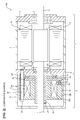
Fig. 1 is a vertical cross-sectional view showing an entire configuration of a motor in relation to an embodiment. -
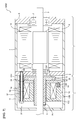
Fig. 2 is a vertical cross-sectional view showing an entire configuration of a motor in relation to Comparative Example. -
Fig. 3 is a vertical cross-sectional view showing an entire configuration of a motor in relation to a modified example in which a flange is disposed in a collar. -
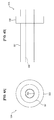
Fig. 4A is a front view showing an entire configuration of the collar with the flange. -
Fig. 4B is a side view showing an entire configuration of the collar with the flange. -
Fig. 5A is a front view showing an entire configuration of the collar with a protruding portion. -
Fig. 5B is a side view showing an entire configuration of the collar with a protruding portion. -
Fig. 6A is a front view showing the entire configuration of a collar with a D cut portion. -
Fig. 6B is a side view showing the entire configuration of a collar with a D cut portion. -
Fig. 7 is a vertical cross-sectional view showing the entire configuration of a motor in relation to a modified example in which the collar is insert-molded on a field core. -
Fig. 8 is a vertical cross-sectional view showing the entire configuration of a motor in relation to a modified example in which the collar is inserted into a concave portion of an opposite load side bracket. - Hereinafter, an embodiment will be explained with reference to the drawings.
- As shown in
Fig. 1 , amotor 100 in relation to the embodiment has amotor body unit 1 that outputs rotation power, and abrake unit 2. Themotor body unit 1 includes arotary shaft 3, aframe 4, aload side bracket 5 disposed on a load side (the right side inFig. 1 , the same is applied below) end of theframe 4, and an oppositeload side bracket 6 disposed on an opposite load side (the side opposite to the load side, left side inFig. 1 , the same is applied below) end of theframe 4. Thebracket load side bracket 5 and the oppositeload side bracket 6, there are disposed a load side bearing 7 and an opposite load side bearing 8, respectively, that rotatably support therotary shaft 3. In the example, the load side bearing 7 is configured to have a size larger than that of the opposite load side bearing 8. Meanwhile, the oppositeload side bracket 6 corresponds to a housing. - Further, the
motor body unit 1 has arotor 9 disposed on therotary shaft 3, and astator 10 that is disposed on the inner circumference face of theframe 4 so as to be arranged radially, facing therotor 9 via a magnetic air gap. - The
brake unit 2 is fixed to the oppositeload side bracket 6 of themotor body unit 1 with a bolt, and performs braking or holding of therotary shaft 3. Meanwhile, in the embodiment, thebrake unit 2 is arranged on the opposite load side of themotor body unit 1, but it may be arranged on the load side of themotor body unit 1. Thebrake unit 2 is covered with abrake cover 11 disposed on the opposite load side of the oppositeload side bracket 6. Thebrake unit 2 has acylindrical field core 12, anannular armature 13 arranged, facing the load side of thefield core 12, abraking spring 14, and abrake disc 15. Meanwhile, thefield core 12 corresponds to a fixing member. - The
field core 12 includes an innercylindrical portion 12A, an outercylindrical portion 12B, and abase plate portion 12C. A ring-like space in the radius direction between the innercylindrical portion 12A and the outercylindrical portion 12B serves as aconcave portion 18 for coil that opens on one side in the cylindrical axis direction. In theconcave portion 18 for a coil, acoil 19, which gives magnetic attractive force toward the opposite load side to thearmature 13 in a conduction state, is housed. Meanwhile, faces of the innercylindrical portion 12A and the outercylindrical portion 12B on the load side (that is, the face of thefield core 12 on the side facing the armature 13) serve as a magnetic pole face that attracts magnetically thearmature 13. On the load side face of the outercylindrical portion 12B, pluralconcave portions 20 for a spring are disposed at suitable regular spaces in a circumferential direction. In each of theseconcave portions 20 for a spring, thebraking spring 14 is housed so as to be interposed between thefield core 12 and thearmature 13. Thesebrake springs 14 apply an urging force on thearmature 13 for pressing toward the load side. Furthermore, on the outercylindrical portion 12B, throughholes 32 for abolt 31 are disposed at suitable regular spaces in a circumferential direction. Thefield core 12 is fixed to the oppositeload side bracket 6 withplural bolts 31 via acollar 33 to be described later. - The
collar 33 is a cylindrical member including, for example, non-magnetic stainless steel. Thecollar 33 is arranged in plural between themotor body unit 1 and thebrake unit 2 and is inserted with thebolt 31, and forms a gap between the oppositeload side bracket 6 and thefield core 12. Each of thecollars 33 is arranged in a position corresponding to the throughhole 32 of thefield core 12 in the circumference direction. As to each of thecollars 33, the load side end is insert-molded on the oppositeload side bracket 6 and fixed thereto. In the example, the load side end of thecollar 33 is in a state of being inserted into the oppositeload side bracket 6 so that a loadside end face 33a of thecollar 33 is approximately flush with aninside surface 6a of the oppositeload side bracket 6. Inside thecollar 33, afemale screw 33b is formed, and thebolt 31 passes through the through hole 32 (no screw is formed) of thefield core 12 and is screwed with thefemale screw 33b of thecollar 33. An opposite loadside end face 33c of thecollar 33 butts on the magnetic pole face of thefield core 12. Thecollar 33 having such configuration adjusts the space between the oppositeload side bracket 6 and thefield core 12 at a portion projecting from the oppositeload side bracket 6, and secures a gap G between the brake disc 15 (in detail, aflange 15D to be described later) and the oppositeload side bracket 6. Further, it engages with anotch 34 formed in the outer circumference portion of thearmature 13 to prevent the rotation of thearmature 13. - The
armature 13 includes a magnetic body (a steel plate or the like), and is supported movably relative to thefield core 12 in the shaft direction of therotary shaft 3. Thearmature 13 is pressed to the load side by a spring force of thebraking spring 14, and is engaged frictionally with the opposite load side face of the brake disc 15 (in detail, aflange 15D to be described later) via afriction plate 26 to be described later. Further, in the outer circumference portion in the radius direction of thearmature 13,plural notches 34 to engage with thecollar 33 are formed. - The
brake disc 15 has acylindrical boss portion 15C that passes through the central portion of thearmature 13 and thefield core 12, and aflange 15D disposed on the load side end of theboss portion 15C. To the face on the opposite load side on the outer circumference side in theflange 15D (the face on the side facing the armature 13), a ring-like friction plate 26 is attached. Theboss portion 15C is formed in a length so that the opposite load side end projects from thefield core 12, and, on the outer circumference face of the projecting portion, ascrew hole 28 for a fixingscrew 27 is disposed. With the fixingscrew 27, thebrake disc 15 is fixed to therotary shaft 3. - In the
brake unit 2, in a state where thecoil 19 is not applied with power (non-excited state), thearmature 13 is pressed toward the load side by the spring force of thebraking spring 14 and thearmature 13 engages frictionally with thebrake disc 15 via thefriction plate 26. Thearmature 13 is configured not to rotate at this time by the engagement of thecollar 33 with thenotch 34 of thearmature 13. As the result, thebrake disc 15 is braked and the rotation of therotary shaft 3 is braked. As described above, thebrake unit 2 causes therotary shaft 3 in the inertial rotation to stop moving, or, when force for rotation is applied from an outside to therotary shaft 3 that is at rest, maintains the state of rest of therotary shaft 3 by holding therotary shaft 3. On the other hand, when thecoil 19 is in a conduction state (excited state), since thecoil 19 gives magnetic attractive force to thearmature 13 toward the opposite load side, thearmature 13 moves to the opposite load side while resisting the spring force of thebraking spring 14. As the result, thebrake disc 15 is released from the braking and therotary shaft 3 becomes rotatable. - Here, before explaining the effect of the embodiment that has been explained above, Comparative Example for explaining the effect of the embodiment will be explained below.
- As shown in
Fig. 2 , in a motor 100' in relation to Comparative Example, points different from amotor 100 in relation to the embodiment are a point in which a collar 33' is included instead of thecollar 33, and a point in which the oppositeload side bracket 6 includes ascrew hole 6b for thebolt 31. The collar 33' does not have a configuration in which the end thereof is inserted into the oppositeload side bracket 6, differing from thecollar 33, but is disposed, being interposed between the oppositeload side bracket 6 and thefield core 12. Further, no female screw is formed inside the collar 33', but thebolt 31 passes through the throughhole 32 of thefield core 12 and the collar 33', and is screwed into thescrew hole 6b of the oppositeload side bracket 6. The other configurations are the same as those of the embodiment. Meanwhile, inFig. 2 , the same symbols are attached to the same structures as those inFig. 1 . - In the motor 100' of the above configuration, the attaching work of the brake is performed by a following procedure. Meanwhile, in the
brake unit 2, thefield core 12, thearmature 13 and thebrake disc 15 are built up integrally with a fixing member which is not illustrated, before the attaching to themotor body unit 1. The fixing member is a member for building up integrally thefield core 12, thearmature 13 and thebrake disc 15, while adjusting the space between thearmature 13 and thefield core 12, by being fixed to theboss portion 15C of thebrake disc 15 in the state of abutting on the face of thefield core 12 on the opposite load side. - When attaching the
brake unit 2 built up integrally by the fixing member to themotor body unit 1, first, the collar 33' is arranged on thescrew hole 6b of the oppositeload side bracket 6, in a state where the opposite load side of themotor body unit 1 is directed upward. Next, after applying an adhesive onto theboss portion 15C of thebrake disc 15, therotary shaft 3 is inserted, and thebrake unit 2 is attached to themotor body unit 1 so that the collar 33' goes through thenotch 34 of thearmature 13. Then, thebolt 31 is caused to pass through the throughhole 32 of thefield core 12 and the collar 33', and is tightened to thescrew hole 6b of the oppositeload side bracket 6 to fix thefield core 12 to the oppositeload side bracket 6. Subsequently, thebrake disc 15 is fixed to therotary shaft 3 with a fixingscrew 27, and the fixing member is removed. - As described above, in the brake attaching work of the motor 100' in Comparative Example, the attaching of the
brake unit 2 is performed in a state where the collar 33' is simply placed on the oppositeload side bracket 6 and, therefore, there is a problem of poor workability, because thearmature 13 or the like may contact with the collar 33' on the oppositeload side bracket 6 to generate the falling down or falling off of the collar 33'. - In contrast, in the
motor 100 of the embodiment shown inFig. 1 , although the brake attaching work is performed in the same procedure as above, since it is configured so that the end of thecollar 33 is inserted into the oppositeload side bracket 6, the generation of the falling down or falling off of thecollar 33 can be prevented in the attaching work of thebrake unit 2. Accordingly, the workability in the brake attaching can be improved. - Meanwhile, in order to prevent the falling down or falling off of the
collar 33, molding integrally the oppositeload side bracket 6 and thecollar 33 with the same material will be considered, but, since thebracket motor 100 is configured with aluminum or the like that has lightweight and good thermal conductivity as described above, thecollar 33 is to be of the same material. However, on thecollar 33, the rotation power of thearmature 13 engaging frictionally with thebrake disc 15 acts, and tensile force by the spring force of thebraking spring 14 also acts in the brake operation, and, therefore, high strength is necessary and the strength may be insufficient in the case of aluminum or the like. On the other hand, in order to dissolve the insufficient strength, when thecollar 33 and the oppositeload side bracket 6 are molded integrally with stainless steel or the like having large strength, the oppositeload side bracket 6 is to be made of stainless steel, which has thermal conductivity lower than that of aluminum or the like and has larger weight. Therefore, heat radiating property of themotor 100 deteriorates and the weight increases. - In the embodiment, since the opposite
load side bracket 6 and thecollar 33 are set to be independent bodies and, then, an inserted configuration is adopted, each can include a suitable material and the workability in the brake attaching can be improved. That is, when causing thebracket collar 33 to include non-magnetic stainless steel or the like, the weight reduction of the motor can be achieved with good heat radiating property, and the strength of thecollar 33 can be secured sufficiently. - Meanwhile, in order to prevent the falling down or falling off of the collar, a configuration, in which a collar itself is not disposed, is also considered. Specifically, a configuration, in which a flange is disposed in the outer circumference portion of the field core and is attached to a projection disposed on the opposite load side bracket thereby to secure the gap between the field core and the opposite load side bracket according to the height of the projection, etc., are considered. In this case, since the projection is arranged in the outer circumference of the field core, it becomes possible to widen the outer diameter of the brake disc up to the vicinity of the outer circumference of the field core, and, since the rotation radius of the friction face increases, such an effect that brake torque can be increased (when brake torque is set to be similar to that in the past, the size of the brake can be reduced because of the reduction of the field core) can be expected. In the configuration, since no collar is disposed, it is necessary to achieve the prevention of rotation of the armature by inserting a pin or the like into the armature and the field core. However, the pin or the like has lower strength as compared with the collar, and, since it is considered to be disposed on an inner circumference side as compared with the collar, the holding power of the armature may become insufficient. In particular, as the size of a motor becomes larger, the brake torque also increases, and, therefore, the insufficiency of holding power of the armature is concerned.
- In the embodiment, since the
collar 33 is disposed, and, in addition, thecollar 33 includes non-magnetic stainless steel or the like to secure the strength sufficiently, the rotation of the armature in brake operation can be prevented reliably even in a motor of a large size. Accordingly, themotor 100 with high reliability on the brake can be actualized. - Further, in the embodiment in particular, the
collar 33 is insert-molded on the oppositeload side bracket 6 and thecollar 33 and the oppositeload side bracket 6 are configured integrally. Consequently, a work of arranging thecollar 33 on the oppositeload side bracket 6 in attaching thebrake unit 2 becomes unnecessary and a man-hour can be reduced. Further, by insert-molding thecollar 33 on the oppositeload side bracket 6, as compared with the structure in Comparative Example in which the collar 33' is arranged on thebracket 6 as shown inFig. 2 , the contact area between thecollar 33 and the oppositeload side bracket 6 can be increased. Consequently, heat generated on themotor body unit 1 side can easily be transmitted to thebrake unit 2 side via heat conduction between the oppositeload side bracket 6 and thecollar 33, and the heat radiation property of themotor 100 can be improved. - Further, in the embodiment in particular, the
female screw 33b is formed inside thecollar 33 and the fieldcore attaching bolt 31 is screwed into thefemale screw 33b of thecollar 33. Consequently, as compared with the structure in Comparative Example shown inFig. 2 , the tightening length of the bolt 31 (in the embodiment, it is approximately the same as the length of thecollar 33, but, in Comparative Example, it is approximately the same as the thickness of the bracket 6) can be increased, and the bolt can be tightened to thecollar 33 including stainless steel or the like having strength larger than thebracket 6 including aluminum or the like. Accordingly, it becomes possible to increase the tightening force significantly by thebolt 31 and the attaching stability of thebrake unit 2 can be improved significantly. Meanwhile, in the embodiment, the length of thebolt 31 is set to be the same length as that in Comparative Example, but, when designing the tightening force to be the same degree as that in Comparative Example, it is sufficient to cause thebolt 31 to be screwed into a part of the portion projecting from thebracket 6 in thecollar 33. In this case, thebolt 31 may be shortened as compared with Comparative Example. Accordingly, the embodiment can contribute to size reduction of parts and reduction of the motor weight. - Further, in the embodiment in particular, the
collar 33 includes non-magnetic stainless steel or the like. Consequently, while maintaining sufficiently the strength of thecollar 33, no influence is given to the motion of thearmature 13 being a magnetic body. Accordingly, themotor 100 with high reliability can be actualized. - Meanwhile, the embodiment is not limited to the above contents, but various modifications are possible in the range that does not deviate from the gist and the technical idea thereof. Hereinafter, such modified examples will be explained in order.
- On the
collar 33, since a tensile force by the spring force of thebraking spring 14 acts in brake operation, the prevention of thecollar 33 from falling off may be attempted. An example is shown inFig. 3 andFigs. 4A and 4B . - As shown in
Fig. 3 andFigs. 4A and 4B , acollar 33A of the modified example has a cylindricalcollar body portion 331 with afemale screw 33b formed inside, and aflange 332 disposed in the outer circumference of thecollar body portion 331. Theflange 332 is formed with an outer diameter larger than that of other parts of thecollar body portion 331, and is disposed on a part to be inserted into the oppositeload side bracket 6 in the insert-molding of thecollar 33A. Configurations other than thecollar 33A are the same as those in the embodiment. Meanwhile, in the example, theflange 332 is disposed continuously over a round of the outer circumference face of thecollar body portion 331, but it may be disposed partially or discontinuously in the circumference direction. - According to the modified example, since the falling down or falling off of the
collar 33A from the oppositeload side bracket 6 can be prevented, the attaching stability of the brake can be improved further. - Since the rotation power acts on the
collar 33 in fastening thebolt 31, a rotation preventing structure may be disposed on thecollar 33. InFigs. 5A and 5B andFigs. 6A and 6B , an example of the rotation preventing structure is shown. - In the example shown in
Figs. 5A and 5B , acollar 33B has the cylindricalcollar body portion 331 with thefemale screw 33b formed inside, theflange 332, and plural (four in the example) protrudingportions 333 disposed on the outer circumference face of thecollar body portion 331, extending along a cylindrical axis direction (inFig. 5B , the right-left direction). Each of the protrudingportions 333 projects from the outer circumference face of thecollar body portion 331 toward the outside in the diameter direction, and the shape of cross-section (cross-section in the axis direction) thereof is approximately rectangular. Further, each of the protrudingportions 333 is disposed at approximately 90-degree intervals in the circumference direction. As the result that these protrudingportions 333 engage with the oppositeload side bracket 6, the rotation of thecollar 33B can be prevented. Meanwhile, in the example, the protrudingportion 333 is disposed only on one side of the flange 332 (inFig. 5B , the left side), but it may be disposed on both sides of theflange 332. Further, the number of the protrudingportions 333 is not limited to four, but may be more than one, and the cross-sectional shape thereof is not limited to a rectangle but may be a triangle, an ellipsoid, or the like. Further, without disposing theflange 332 on the outer circumference face of thecollar body portion 331, the protrudingportion 333 may be disposed over the entire cylindrical axis direction. - In the example shown in
Figs. 6A and 6B , thecollar 33C has the cylindricalcollar body portion 331 with thefemale screw 33b formed inside, theflange 332, and the D cutportion 334 disposed on the outer circumference face of thecollar body portion 331. As the result that the D cutportion 334 engages with the oppositeload side bracket 6, the rotation of thecollar 33C can be prevented. Meanwhile, in the example, the D cutportion 334 is disposed only on one side of the flange 332 (inFig. 6B , the left side), but it may be disposed on both sides of theflange 332. Further, without disposing theflange 332 on the outer circumference face of thecollar body portion 331, the D cutportion 334 may be disposed over the entire cylindrical axis direction. - According to the modified example, by disposing the protruding
portion 333 or the D cutportion 334 on the outer circumference face of thecollar collar load side bracket 6 in fastening a bolt can be prevented. Therefore, it becomes possible to fasten sufficiently thebolt 31 and the attaching stability of the brake can be improved further. - In the embodiment, the collar is insert-molded on the opposite load side bracket side, but it may be insert-molded on the field core side.
- As shown in
Fig. 7 , in amotor 100D of the modified example, the opposite load side end of acollar 33D is insert-molded on thefield core 12 and fixed thereto. Thecollar 33D includes non-magnetic stainless steel or the like as is the case for thecollar 33, but, differing from thecollar 33, no female screw is formed inside. That is, thebolt 31 passes through the throughhole 32 of thefield core 12 and thecollar 33D, and is screwed into thescrew hole 6b of the oppositeload side bracket 6. Other configurations are the same as those in the embodiment. - In the modified example, since such a configuration is adopted that the end of the
collar 33D is inserted into thefield core 12, the generation of the falling down or falling off of thecollar 33D in the attaching work of thebrake unit 2 can be prevented. Accordingly, workability in attaching a brake can be improved. Further, a work of arranging thecollar 33D on the opposite load side bracket 6 (or on the field core 12) becomes unnecessary in attaching the brake and a man-hour can be reduced. - Furthermore, the surface of the opposite
load side bracket 6 on thebrake unit 2 side is occasionally subjected to a flattening processing in order to make the gap between the oppositeload side bracket 6 and the brake disc 15 (for achieving size reduction of themotor 100D in the axis direction) minute, but, when thecollar 33D is molded integrally on the oppositeload side bracket 6 side, the processing cannot be performed. In the modified example, since thecollar 33D is molded integrally on thefield core 12 side, the surface processing of the oppositeload side bracket 6 can be performed, and the size reduction of themotor 100D can be achieved. - Meanwhile, it is considered to mold integrally the
field core 12 and thecollar 33D with the same material in order to prevent the falling down or falling off of thecollar 33D, but, in the case, since thefield core 12 includes a magnetic body, thecollar 33D also includes a magnetic body, which may influence on the motion of thearmature 13 located in the vicinity. In the modified example, since such a configuration is adopted that thefield core 12 is set to be an independent body from thecollar 33D and then is inserted. Therefore, when thecollar 33D includes a non-magnetic body (non-magnetic stainless steel or the like), it gives no influence on the motion of thearmature 13 being a magnetic body. - In the embodiment, the
collar 33 is insert-molded on the oppositeload side bracket 6 and fixed, but thecollar 33 is not necessarily to be fixed. For example, a concave portion for inserting the collar is disposed on at least one of the oppositeload side bracket 6 and thefield core 12, and then the collar may be inserted into the concave portion in attaching a brake. InFig. 8 , an example is shown. - In the example shown in
Fig. 8 , aconcave portion 6c is disposed on the surface of a part on brake side corresponding to thescrew hole 6b of the oppositeload side bracket 6. In theconcave portion 6c, acollar 33E has been inserted. Theconcave portion 6c and thecollar 33E are not fixed in particular, but may be fixed with an adhesive or the like. In the modified example, thecollar 33E is inserted into theconcave portion 6c of the oppositeload side bracket 6 in attaching a brake. At this time, an adhesive may be applied to theconcave portion 6c. Subsequently, thebrake unit 2 is attached to themotor body unit 1. - In the modified example, too, since such a configuration is adopted that the end of the
collar 33E has been inserted into the oppositeload side bracket 6, such probability that the falling down or falling off of thecollar 33 is generated in the attaching work of thebrake unit 2 can be reduced. Accordingly, workability in attaching a brake can be improved. - Meanwhile, in the description, the
concave portion 6c is disposed on the oppositeload side bracket 6, but a concave portion may be disposed on thefield core 12, or a concave portion may be disposed on both the oppositeload side bracket 6 and thefield core 12. - The
brake unit 2 explained in the embodiment is an example, and the structure of the brake is not limited to this. The invention may be applied irrespective of the shape and type of a brake, only if it is one which is fixed to the housing of the motor body unit with a bolt and forms a gap between the housing of the motor body unit and the fixing member of the brake unit with a collar. - Further, in addition to matters described above, techniques by the embodiment and each of the modified examples may be combined suitably and utilized.
- In addition, although not exemplified point by point, the embodiment and each of the modified examples will be brought into practice after the addition of various changes in the range that does not deviate from the purport thereof.
-
- 1:
- motor body unit
- 2:
- brake unit
- 3:
- rotary shaft
- 6:
- opposite load side bracket (housing)
- 8:
- opposite load side bearing (bearing)
- 9:
- rotor
- 10:
- stator
- 12:
- field core (fixing member)
- 13:
- armature
- 15:
- brake disc
- 19:
- coil
- 31:
- bolt
- 33:
- collar
- 33b:
- female screw
- 33A - E:
- collar
- 34:
- notch
- 100:
- motor
- 100A, D, E:
- motor
- 332:
- flange
- 333:
- protruding portion (rotation preventing structure)
- 334:
- D cut portion (rotation preventing structure)
Claims (6)
- A motor comprising:a motor body unit configured to output rotation power;a brake unit fixed to a housing of the motor body unit with a bolt; anda collar arranged between the motor body unit and the brake unit, in which the bolt is inserted, the collar forming a space between the housing of the motor body unit and a fixing member of the brake unit, wherein:the collar is fixed with its end portion being inserted into at least one of the housing and the fixing member.
- The motor according to claim 1, wherein:the motor body unit comprisesa rotor disposed on a rotary shaft,a stator arranged to face the rotor in a radius direction via a magnetic air gap, andthe housing in which a bearing supporting the rotary shaft is disposed, andthe brake unit comprisesa field core as the fixing member fixed to the housing with the bolt, the field core housing a coil,an armature supported movably relative to the field core in a shaft direction of the rotary shaft, the armature comprising a notch engaging with the collar on an outer circumference portion, anda brake disc fixed to the rotary shaft, the brake disc being configured to engage frictionally with the armature.
- The motor according to claim 1 or 2, wherein:the collar is fixed with its end portion on the housing side being insert-molded in the housing.
- The motor according to claim 3, wherein:the collar comprises a flange in an insertion portion into the housing.
- The motor according to claim 3 or 4, wherein:a female screw into which the bolt is screwed is formed inside the collar.
- The motor according to claim 5, wherein:the collar comprises a rotation preventing structure preventing rotation relative to the housing.
Applications Claiming Priority (1)
| Application Number | Priority Date | Filing Date | Title |
|---|---|---|---|
| PCT/JP2011/080199 WO2013098936A1 (en) | 2011-12-27 | 2011-12-27 | Motor |
Publications (2)
| Publication Number | Publication Date |
|---|---|
| EP2800249A1 true EP2800249A1 (en) | 2014-11-05 |
| EP2800249A4 EP2800249A4 (en) | 2016-07-20 |
Family
ID=48696506
Family Applications (1)
| Application Number | Title | Priority Date | Filing Date |
|---|---|---|---|
| EP11878578.1A Withdrawn EP2800249A4 (en) | 2011-12-27 | 2011-12-27 | ENGINE |
Country Status (6)
| Country | Link |
|---|---|
| US (1) | US9112388B2 (en) |
| EP (1) | EP2800249A4 (en) |
| JP (1) | JP5267750B1 (en) |
| CN (1) | CN104054239B (en) |
| BR (1) | BR112014015685A8 (en) |
| WO (1) | WO2013098936A1 (en) |
Families Citing this family (9)
| Publication number | Priority date | Publication date | Assignee | Title |
|---|---|---|---|---|
| DE102015005360B3 (en) * | 2015-04-28 | 2016-06-23 | Sew-Eurodrive Gmbh & Co Kg | transmission system |
| FR3046307B1 (en) * | 2015-12-23 | 2018-07-06 | Moteurs Leroy-Somer | BRAKE FOR ROTATING ELECTRICAL MACHINE |
| US10576644B2 (en) * | 2017-03-31 | 2020-03-03 | Kinova Inc. | Articulated mechanism with internal brake assembly |
| CN107834763B (en) * | 2017-11-23 | 2024-09-10 | 浙江联宜电机有限公司 | Unidirectional rotating motor |
| CN110835065B (en) * | 2018-08-17 | 2022-02-01 | 奥的斯电梯公司 | Elevator braking device and elevator system |
| KR102532529B1 (en) | 2021-03-02 | 2023-05-15 | 경북대학교 산학협력단 | Motor and Motor Cooling System |
| KR20220127556A (en) | 2021-03-11 | 2022-09-20 | 경북대학교 산학협력단 | Motor and motor cooling system |
| KR102597645B1 (en) | 2021-04-06 | 2023-11-02 | 경북대학교 산학협력단 | Motor and Motor cooling system including cooling module |
| CN113659788A (en) * | 2021-08-13 | 2021-11-16 | 常州隆耐电驱动技术有限公司 | Birotor permanent magnet synchronous driving motor |
Family Cites Families (12)
| Publication number | Priority date | Publication date | Assignee | Title |
|---|---|---|---|---|
| US4142610A (en) * | 1977-11-14 | 1979-03-06 | Eaton Corporation | Self adjusting hoist brake |
| IT7923154U1 (en) * | 1979-11-16 | 1981-05-16 | Setti Luciano | IMPROVED ELECTROMAGNETIC BRAKE, FOR SELF-BRAKING MOTORS, EQUIPPED WITH MANUAL ADJUSTMENT OF THE CLEARANCE BETWEEN THE BRAKING PLATE AND THE ANCHOR |
| EP0250405B1 (en) * | 1985-02-20 | 1991-05-02 | ZF FRIEDRICHSHAFEN Aktiengesellschaft | Annular magnet for motor brakes |
| JP2569457Y2 (en) * | 1992-06-15 | 1998-04-22 | 横河プレシジョン株式会社 | Interface device for magnetic resolver |
| JP2598364Y2 (en) * | 1992-08-17 | 1999-08-09 | タブチテック株式会社 | Drive motor braking mechanism |
| US6459182B1 (en) * | 1998-05-14 | 2002-10-01 | Sew-Eurodrive Gmbh | Electric motor with brake |
| AT408394B (en) * | 1998-05-29 | 2001-11-26 | Atb Austria Antriebstech Ag | DEVICE FOR BRAKING ELECTRIC MOTORS |
| JP5168969B2 (en) * | 2007-03-23 | 2013-03-27 | 株式会社安川電機 | Brake rotor, electromagnetic brake thereof, and motor with electromagnetic brake using the same |
| CN100554130C (en) * | 2008-04-16 | 2009-10-28 | 苏州通润驱动设备股份有限公司 | Plate disc brake |
| US8227948B1 (en) * | 2009-01-09 | 2012-07-24 | Hydro-Gear Limited Partnership | Electric motor |
| CN101902090B (en) * | 2009-05-26 | 2012-12-05 | 建准电机工业股份有限公司 | Motor, fan and stator device thereof |
| JP2011190918A (en) * | 2010-03-17 | 2011-09-29 | Yaskawa Electric Corp | Brake device and rotating electric machine |
-
2011
- 2011-12-27 JP JP2012554551A patent/JP5267750B1/en not_active Expired - Fee Related
- 2011-12-27 WO PCT/JP2011/080199 patent/WO2013098936A1/en not_active Ceased
- 2011-12-27 BR BR112014015685A patent/BR112014015685A8/en not_active IP Right Cessation
- 2011-12-27 CN CN201180075937.XA patent/CN104054239B/en not_active Expired - Fee Related
- 2011-12-27 EP EP11878578.1A patent/EP2800249A4/en not_active Withdrawn
-
2014
- 2014-06-24 US US14/312,695 patent/US9112388B2/en not_active Expired - Fee Related
Also Published As
| Publication number | Publication date |
|---|---|
| BR112014015685A8 (en) | 2017-07-04 |
| CN104054239A (en) | 2014-09-17 |
| JPWO2013098936A1 (en) | 2015-04-30 |
| CN104054239B (en) | 2016-09-07 |
| US9112388B2 (en) | 2015-08-18 |
| JP5267750B1 (en) | 2013-08-21 |
| WO2013098936A1 (en) | 2013-07-04 |
| BR112014015685A2 (en) | 2017-06-13 |
| EP2800249A4 (en) | 2016-07-20 |
| US20140300229A1 (en) | 2014-10-09 |
Similar Documents
| Publication | Publication Date | Title |
|---|---|---|
| US9112388B2 (en) | Motor | |
| JP5397409B2 (en) | motor | |
| US9263923B2 (en) | Electric motor having first frame and second frame fastened together with through bolt | |
| US20140062245A1 (en) | Rotor for rotating electric machine | |
| US20110140557A1 (en) | Linear actuator | |
| US20140254632A1 (en) | Instrument for adjoining temperature detecting element | |
| KR101992818B1 (en) | Motor structure | |
| JP6238054B2 (en) | Inner rotor type motor | |
| US9557564B2 (en) | Rotary body driving apparatus | |
| JP2012122574A (en) | Electromagnetic brake and electric motor | |
| CN107869538B (en) | Electromagnetic brake | |
| US9906088B2 (en) | Rotor-holding structure of rotating electrical machine for hybrid vehicle | |
| JP5354308B2 (en) | Motor, motor brake, and motor manufacturing method | |
| JPH07245909A (en) | Motor with electromagnetic brake | |
| JP2008312402A (en) | Axial air gap type electric motor | |
| JP2016005375A (en) | Switched reluctance motor | |
| TW200809114A (en) | Spring actuated electromagnetic brake | |
| JP2006038808A (en) | Resolver stator fixing structure | |
| CN213243666U (en) | Integrated structure of axial magnetic field motor and double-friction-surface brake | |
| JP2014050274A (en) | Rotor for surface magnet affixed rotary electric machine | |
| US9106111B2 (en) | Outer body of an electromechanical energy converter | |
| CN117859256A (en) | Motor with braking device | |
| JP2008043157A (en) | Inner rotor, and generator with inner rotor | |
| US20080054754A1 (en) | End plate for electric motor | |
| JP2011200027A (en) | Motor with reduction gear, and mechanical device equipped with the motor |
Legal Events
| Date | Code | Title | Description |
|---|---|---|---|
| PUAI | Public reference made under article 153(3) epc to a published international application that has entered the european phase |
Free format text: ORIGINAL CODE: 0009012 |
|
| 17P | Request for examination filed |
Effective date: 20140618 |
|
| AK | Designated contracting states |
Kind code of ref document: A1 Designated state(s): AL AT BE BG CH CY CZ DE DK EE ES FI FR GB GR HR HU IE IS IT LI LT LU LV MC MK MT NL NO PL PT RO RS SE SI SK SM TR |
|
| DAX | Request for extension of the european patent (deleted) | ||
| RA4 | Supplementary search report drawn up and despatched (corrected) |
Effective date: 20160616 |
|
| RIC1 | Information provided on ipc code assigned before grant |
Ipc: F16D 55/02 20060101ALI20160610BHEP Ipc: H02K 7/102 20060101ALI20160610BHEP Ipc: H02K 5/04 20060101AFI20160610BHEP |
|
| STAA | Information on the status of an ep patent application or granted ep patent |
Free format text: STATUS: THE APPLICATION HAS BEEN WITHDRAWN |
|
| 18W | Application withdrawn |
Effective date: 20160719 |