EP2800111A2 - Wireless power transfer system transducers having interchangeable source resonator and capture resonator - Google Patents
Wireless power transfer system transducers having interchangeable source resonator and capture resonator Download PDFInfo
- Publication number
- EP2800111A2 EP2800111A2 EP14165669.4A EP14165669A EP2800111A2 EP 2800111 A2 EP2800111 A2 EP 2800111A2 EP 14165669 A EP14165669 A EP 14165669A EP 2800111 A2 EP2800111 A2 EP 2800111A2
- Authority
- EP
- European Patent Office
- Prior art keywords
- resonator
- capture
- transducer
- source
- transfer system
- Prior art date
- Legal status (The legal status is an assumption and is not a legal conclusion. Google has not performed a legal analysis and makes no representation as to the accuracy of the status listed.)
- Granted
Links
- 239000000463 material Substances 0.000 claims description 10
- RYGMFSIKBFXOCR-UHFFFAOYSA-N Copper Chemical compound [Cu] RYGMFSIKBFXOCR-UHFFFAOYSA-N 0.000 claims description 7
- 229910052802 copper Inorganic materials 0.000 claims description 7
- 239000010949 copper Substances 0.000 claims description 7
- 230000035699 permeability Effects 0.000 claims description 3
- 229910000859 α-Fe Inorganic materials 0.000 claims description 3
- 238000000034 method Methods 0.000 description 14
- 229910052782 aluminium Inorganic materials 0.000 description 6
- XAGFODPZIPBFFR-UHFFFAOYSA-N aluminium Chemical compound [Al] XAGFODPZIPBFFR-UHFFFAOYSA-N 0.000 description 6
- 239000004033 plastic Substances 0.000 description 6
- 229920003023 plastic Polymers 0.000 description 6
- 230000000712 assembly Effects 0.000 description 5
- 238000000429 assembly Methods 0.000 description 5
- 238000004519 manufacturing process Methods 0.000 description 5
- 239000000853 adhesive Substances 0.000 description 4
- 230000001070 adhesive effect Effects 0.000 description 4
- 238000001746 injection moulding Methods 0.000 description 3
- 229920001707 polybutylene terephthalate Polymers 0.000 description 3
- 229920000139 polyethylene terephthalate Polymers 0.000 description 3
- 239000005020 polyethylene terephthalate Substances 0.000 description 3
- -1 polypropylene Polymers 0.000 description 3
- 239000004677 Nylon Substances 0.000 description 2
- 239000004743 Polypropylene Substances 0.000 description 2
- 229910045601 alloy Inorganic materials 0.000 description 2
- 239000000956 alloy Substances 0.000 description 2
- 230000008901 benefit Effects 0.000 description 2
- 239000004020 conductor Substances 0.000 description 2
- 239000012811 non-conductive material Substances 0.000 description 2
- 229920001778 nylon Polymers 0.000 description 2
- 229920001155 polypropylene Polymers 0.000 description 2
- 229910000976 Electrical steel Inorganic materials 0.000 description 1
- XEEYBQQBJWHFJM-UHFFFAOYSA-N Iron Chemical compound [Fe] XEEYBQQBJWHFJM-UHFFFAOYSA-N 0.000 description 1
- 238000013459 approach Methods 0.000 description 1
- 239000003990 capacitor Substances 0.000 description 1
- 239000012141 concentrate Substances 0.000 description 1
- 239000000356 contaminant Substances 0.000 description 1
- 238000005260 corrosion Methods 0.000 description 1
- 230000007797 corrosion Effects 0.000 description 1
- 239000003989 dielectric material Substances 0.000 description 1
- 238000004146 energy storage Methods 0.000 description 1
- 230000007613 environmental effect Effects 0.000 description 1
- 230000004907 flux Effects 0.000 description 1
- 239000003292 glue Substances 0.000 description 1
- 239000012943 hotmelt Substances 0.000 description 1
- 238000003754 machining Methods 0.000 description 1
- 229910052751 metal Inorganic materials 0.000 description 1
- 239000002184 metal Substances 0.000 description 1
- 239000007769 metal material Substances 0.000 description 1
- 150000003839 salts Chemical class 0.000 description 1
- 229920002379 silicone rubber Polymers 0.000 description 1
- 239000004945 silicone rubber Substances 0.000 description 1
- XLYOFNOQVPJJNP-UHFFFAOYSA-N water Substances O XLYOFNOQVPJJNP-UHFFFAOYSA-N 0.000 description 1
- 238000004804 winding Methods 0.000 description 1
Images


Classifications
-
- H—ELECTRICITY
- H01—ELECTRIC ELEMENTS
- H01F—MAGNETS; INDUCTANCES; TRANSFORMERS; SELECTION OF MATERIALS FOR THEIR MAGNETIC PROPERTIES
- H01F38/00—Adaptations of transformers or inductances for specific applications or functions
- H01F38/14—Inductive couplings
-
- B—PERFORMING OPERATIONS; TRANSPORTING
- B60—VEHICLES IN GENERAL
- B60L—PROPULSION OF ELECTRICALLY-PROPELLED VEHICLES; SUPPLYING ELECTRIC POWER FOR AUXILIARY EQUIPMENT OF ELECTRICALLY-PROPELLED VEHICLES; ELECTRODYNAMIC BRAKE SYSTEMS FOR VEHICLES IN GENERAL; MAGNETIC SUSPENSION OR LEVITATION FOR VEHICLES; MONITORING OPERATING VARIABLES OF ELECTRICALLY-PROPELLED VEHICLES; ELECTRIC SAFETY DEVICES FOR ELECTRICALLY-PROPELLED VEHICLES
- B60L53/00—Methods of charging batteries, specially adapted for electric vehicles; Charging stations or on-board charging equipment therefor; Exchange of energy storage elements in electric vehicles
- B60L53/10—Methods of charging batteries, specially adapted for electric vehicles; Charging stations or on-board charging equipment therefor; Exchange of energy storage elements in electric vehicles characterised by the energy transfer between the charging station and the vehicle
- B60L53/12—Inductive energy transfer
- B60L53/122—Circuits or methods for driving the primary coil, e.g. supplying electric power to the coil
-
- B—PERFORMING OPERATIONS; TRANSPORTING
- B60—VEHICLES IN GENERAL
- B60L—PROPULSION OF ELECTRICALLY-PROPELLED VEHICLES; SUPPLYING ELECTRIC POWER FOR AUXILIARY EQUIPMENT OF ELECTRICALLY-PROPELLED VEHICLES; ELECTRODYNAMIC BRAKE SYSTEMS FOR VEHICLES IN GENERAL; MAGNETIC SUSPENSION OR LEVITATION FOR VEHICLES; MONITORING OPERATING VARIABLES OF ELECTRICALLY-PROPELLED VEHICLES; ELECTRIC SAFETY DEVICES FOR ELECTRICALLY-PROPELLED VEHICLES
- B60L53/00—Methods of charging batteries, specially adapted for electric vehicles; Charging stations or on-board charging equipment therefor; Exchange of energy storage elements in electric vehicles
- B60L53/10—Methods of charging batteries, specially adapted for electric vehicles; Charging stations or on-board charging equipment therefor; Exchange of energy storage elements in electric vehicles characterised by the energy transfer between the charging station and the vehicle
- B60L53/12—Inductive energy transfer
- B60L53/126—Methods for pairing a vehicle and a charging station, e.g. establishing a one-to-one relation between a wireless power transmitter and a wireless power receiver
-
- B—PERFORMING OPERATIONS; TRANSPORTING
- B60—VEHICLES IN GENERAL
- B60L—PROPULSION OF ELECTRICALLY-PROPELLED VEHICLES; SUPPLYING ELECTRIC POWER FOR AUXILIARY EQUIPMENT OF ELECTRICALLY-PROPELLED VEHICLES; ELECTRODYNAMIC BRAKE SYSTEMS FOR VEHICLES IN GENERAL; MAGNETIC SUSPENSION OR LEVITATION FOR VEHICLES; MONITORING OPERATING VARIABLES OF ELECTRICALLY-PROPELLED VEHICLES; ELECTRIC SAFETY DEVICES FOR ELECTRICALLY-PROPELLED VEHICLES
- B60L53/00—Methods of charging batteries, specially adapted for electric vehicles; Charging stations or on-board charging equipment therefor; Exchange of energy storage elements in electric vehicles
- B60L53/30—Constructional details of charging stations
- B60L53/34—Plug-like or socket-like devices specially adapted for contactless inductive charging of electric vehicles
-
- B—PERFORMING OPERATIONS; TRANSPORTING
- B60—VEHICLES IN GENERAL
- B60L—PROPULSION OF ELECTRICALLY-PROPELLED VEHICLES; SUPPLYING ELECTRIC POWER FOR AUXILIARY EQUIPMENT OF ELECTRICALLY-PROPELLED VEHICLES; ELECTRODYNAMIC BRAKE SYSTEMS FOR VEHICLES IN GENERAL; MAGNETIC SUSPENSION OR LEVITATION FOR VEHICLES; MONITORING OPERATING VARIABLES OF ELECTRICALLY-PROPELLED VEHICLES; ELECTRIC SAFETY DEVICES FOR ELECTRICALLY-PROPELLED VEHICLES
- B60L53/00—Methods of charging batteries, specially adapted for electric vehicles; Charging stations or on-board charging equipment therefor; Exchange of energy storage elements in electric vehicles
- B60L53/30—Constructional details of charging stations
- B60L53/35—Means for automatic or assisted adjustment of the relative position of charging devices and vehicles
- B60L53/36—Means for automatic or assisted adjustment of the relative position of charging devices and vehicles by positioning the vehicle
-
- B—PERFORMING OPERATIONS; TRANSPORTING
- B60—VEHICLES IN GENERAL
- B60L—PROPULSION OF ELECTRICALLY-PROPELLED VEHICLES; SUPPLYING ELECTRIC POWER FOR AUXILIARY EQUIPMENT OF ELECTRICALLY-PROPELLED VEHICLES; ELECTRODYNAMIC BRAKE SYSTEMS FOR VEHICLES IN GENERAL; MAGNETIC SUSPENSION OR LEVITATION FOR VEHICLES; MONITORING OPERATING VARIABLES OF ELECTRICALLY-PROPELLED VEHICLES; ELECTRIC SAFETY DEVICES FOR ELECTRICALLY-PROPELLED VEHICLES
- B60L53/00—Methods of charging batteries, specially adapted for electric vehicles; Charging stations or on-board charging equipment therefor; Exchange of energy storage elements in electric vehicles
- B60L53/30—Constructional details of charging stations
- B60L53/35—Means for automatic or assisted adjustment of the relative position of charging devices and vehicles
- B60L53/38—Means for automatic or assisted adjustment of the relative position of charging devices and vehicles specially adapted for charging by inductive energy transfer
-
- H—ELECTRICITY
- H01—ELECTRIC ELEMENTS
- H01F—MAGNETS; INDUCTANCES; TRANSFORMERS; SELECTION OF MATERIALS FOR THEIR MAGNETIC PROPERTIES
- H01F27/00—Details of transformers or inductances, in general
- H01F27/28—Coils; Windings; Conductive connections
- H01F27/2823—Wires
-
- H—ELECTRICITY
- H01—ELECTRIC ELEMENTS
- H01F—MAGNETS; INDUCTANCES; TRANSFORMERS; SELECTION OF MATERIALS FOR THEIR MAGNETIC PROPERTIES
- H01F27/00—Details of transformers or inductances, in general
- H01F27/28—Coils; Windings; Conductive connections
- H01F27/32—Insulating of coils, windings, or parts thereof
- H01F27/324—Insulation between coil and core, between different winding sections, around the coil; Other insulation structures
- H01F27/325—Coil bobbins
-
- Y—GENERAL TAGGING OF NEW TECHNOLOGICAL DEVELOPMENTS; GENERAL TAGGING OF CROSS-SECTIONAL TECHNOLOGIES SPANNING OVER SEVERAL SECTIONS OF THE IPC; TECHNICAL SUBJECTS COVERED BY FORMER USPC CROSS-REFERENCE ART COLLECTIONS [XRACs] AND DIGESTS
- Y02—TECHNOLOGIES OR APPLICATIONS FOR MITIGATION OR ADAPTATION AGAINST CLIMATE CHANGE
- Y02T—CLIMATE CHANGE MITIGATION TECHNOLOGIES RELATED TO TRANSPORTATION
- Y02T10/00—Road transport of goods or passengers
- Y02T10/60—Other road transportation technologies with climate change mitigation effect
- Y02T10/70—Energy storage systems for electromobility, e.g. batteries
-
- Y—GENERAL TAGGING OF NEW TECHNOLOGICAL DEVELOPMENTS; GENERAL TAGGING OF CROSS-SECTIONAL TECHNOLOGIES SPANNING OVER SEVERAL SECTIONS OF THE IPC; TECHNICAL SUBJECTS COVERED BY FORMER USPC CROSS-REFERENCE ART COLLECTIONS [XRACs] AND DIGESTS
- Y02—TECHNOLOGIES OR APPLICATIONS FOR MITIGATION OR ADAPTATION AGAINST CLIMATE CHANGE
- Y02T—CLIMATE CHANGE MITIGATION TECHNOLOGIES RELATED TO TRANSPORTATION
- Y02T10/00—Road transport of goods or passengers
- Y02T10/60—Other road transportation technologies with climate change mitigation effect
- Y02T10/7072—Electromobility specific charging systems or methods for batteries, ultracapacitors, supercapacitors or double-layer capacitors
-
- Y—GENERAL TAGGING OF NEW TECHNOLOGICAL DEVELOPMENTS; GENERAL TAGGING OF CROSS-SECTIONAL TECHNOLOGIES SPANNING OVER SEVERAL SECTIONS OF THE IPC; TECHNICAL SUBJECTS COVERED BY FORMER USPC CROSS-REFERENCE ART COLLECTIONS [XRACs] AND DIGESTS
- Y02—TECHNOLOGIES OR APPLICATIONS FOR MITIGATION OR ADAPTATION AGAINST CLIMATE CHANGE
- Y02T—CLIMATE CHANGE MITIGATION TECHNOLOGIES RELATED TO TRANSPORTATION
- Y02T90/00—Enabling technologies or technologies with a potential or indirect contribution to GHG emissions mitigation
- Y02T90/10—Technologies relating to charging of electric vehicles
- Y02T90/12—Electric charging stations
-
- Y—GENERAL TAGGING OF NEW TECHNOLOGICAL DEVELOPMENTS; GENERAL TAGGING OF CROSS-SECTIONAL TECHNOLOGIES SPANNING OVER SEVERAL SECTIONS OF THE IPC; TECHNICAL SUBJECTS COVERED BY FORMER USPC CROSS-REFERENCE ART COLLECTIONS [XRACs] AND DIGESTS
- Y02—TECHNOLOGIES OR APPLICATIONS FOR MITIGATION OR ADAPTATION AGAINST CLIMATE CHANGE
- Y02T—CLIMATE CHANGE MITIGATION TECHNOLOGIES RELATED TO TRANSPORTATION
- Y02T90/00—Enabling technologies or technologies with a potential or indirect contribution to GHG emissions mitigation
- Y02T90/10—Technologies relating to charging of electric vehicles
- Y02T90/14—Plug-in electric vehicles
-
- Y—GENERAL TAGGING OF NEW TECHNOLOGICAL DEVELOPMENTS; GENERAL TAGGING OF CROSS-SECTIONAL TECHNOLOGIES SPANNING OVER SEVERAL SECTIONS OF THE IPC; TECHNICAL SUBJECTS COVERED BY FORMER USPC CROSS-REFERENCE ART COLLECTIONS [XRACs] AND DIGESTS
- Y02—TECHNOLOGIES OR APPLICATIONS FOR MITIGATION OR ADAPTATION AGAINST CLIMATE CHANGE
- Y02T—CLIMATE CHANGE MITIGATION TECHNOLOGIES RELATED TO TRANSPORTATION
- Y02T90/00—Enabling technologies or technologies with a potential or indirect contribution to GHG emissions mitigation
- Y02T90/10—Technologies relating to charging of electric vehicles
- Y02T90/16—Information or communication technologies improving the operation of electric vehicles
Definitions
- the invention generally relates to a wireless power transfer system, and more particularly relates to a wireless power transfer system having substantially identical and interchangeable source and capture resonators.
- Wireless electrical power transfer systems are known to incorporate a first resonator structure, hereafter referred to as a source resonator that includes a tuned resonant circuit configured to convert electrical energy from an electrical power source to a magnetic field and to transfer the magnetic energy via the magnetic field to a spaced apart second resonator structure, hereafter referred to as a capture resonator.
- the capture resonator also includes a tuned resonant circuit configured for receiving the magnetic field and converting the magnetic field to electrical energy that is supplied to an electrical load, such as a motor or battery back.
- Such a wireless power transfer system may be used for electrically charging an energy storage device, such as the battery pack of an electric or hybrid electric vehicle.
- the source resonator may be located on, or embedded into, a surface for example the floor of a garage or the surface of a parking lot, and the capture resonator may be disposed on a vehicle.
- the source resonator may be embedded in a roadway and the capture resonator may receive energy to directly provide power to a vehicle motor or to charge the vehicle battery while the vehicle is moving.
- a wireless power transfer system hereafter referred to as the system.
- the system transmits electrical power from an electrical power source to an electrical load using a source resonator and a capture resonator that are inductively coupled.
- Each resonator includes an insulative split carrier-winder assembly having two substantially identical halves. Each half of the split carrier-winder defines an interior core retaining pocket and an outer coil retaining surface. A core tile formed of a material having high magnetic permeability is contained in the interior core retaining pocket of each carrier-winder assembly.
- Each resonator also includes a wire coil that is wound around the outer coil retaining surface of each carrier-winder assembly. Two substantially identical resonators may be used interchangeably as the source resonator or the capture resonator of the system.
- the system further includes a first housing that is configured to contain the source resonator and a first resonator holder that is configured to secure the source resonator within the first housing.
- the system also includes a second housing that is configured to contain the capture resonator and a second resonator holder that is configured to secure the capture resonator within the second housing.
- the first resonator holder and the second resonator holder are substantially identical and are interchangeable.
- the system further may include a first ground plate that is configured to provide an electrical ground plane for the source resonator and is configured to be secured to the first housing.
- the system also includes a second ground plate that is configured to provide an electrical ground plane for the capture resonator and is configured to be secured to the second housing.
- the first ground plate and the second ground plate are substantially identical and are interchangeable.
- the first ground plate and the second ground plate are formed of a copper material.
- the first housing contains a source resonator tuning network
- the second housing contains a capture resonator tuning network
- the inductance values of the source resonator tuning network are different than the inductance values of the capture resonator tuning network whereby the resonant frequency of the source resonator and the capture resonator may be separately tuned.
- the core tile is characterized as a substantially planar rectangular plate.
- the core tile is formed of a ferrite material.
- the outer coil retaining surface defines a plurality of grooves configured to at least partially contain the wire coil.
- Each resonator comprises a plurality of core tiles.
- Each half of the carrier-winder assembly defines a plurality of core retaining pockets.
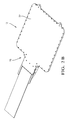
- Fig. 1 illustrates a non-limiting example of a wireless power transfer system 10 that includes two transducers that is suited for wirelessly charging an electric vehicle.
- the first transducer 12 is a source transducer 12 that is coupled to an electrical power supply 14, such as an electric vehicle battery charger.
- the second transducer 16 is a capture transducer 16 that is coupled to an electrical load 18, such as a battery pack of an electric or hybrid electric vehicle 20.
- the source transducer 12 is disposed on the parking surface 22 of a parking lot and the capture transducer 16 is attached to the vehicle 20.
- the source transducer 12 converts electrical energy from the electrical power supply 14 to magnetic energy that is transmitted to the capture transducer 16.
- the capture transducer 16 then converts the magnetic energy to electrical energy that is supplied to the electrical load 18.
- the source transducer 12 includes a source resonator 24 contained within a source transducer housing 26.
- the source transducer housing26 includes a source transducer cover 28, a source transducer seal 30, and source transducer mounting plate 32.
- the capture transducer 16 includes a capture resonator 24 contained within a capture transducer housing 34.
- the capture transducer housing 34 includes a capture transducer cover 36, a capture transducer seal 38, and a capture transducer mounting plate 40. Differences between the source transducer housing 26 and the capture transducer housing 34 are driven by the different operating environments and mounting requirements of each transducer housing 26, 34.
- the source resonator 24 and the capture resonator 24 mounted within the transducer housings 26, 34 are designed so that two substantially identical resonator assemblies 24 may be used interchangeably as the source resonator 24 or the capture resonator 24.
- the transducer covers 28, 36 are preferably formed of a non-conductive material, such as polypropylene (PP) plastic so that they do not affect the magnetic field between the source and capture resonators 24.
- the transducer covers 28, 36 may be fabricated using injection molding, sheet forming, or other plastic fabrication methods well known to those skilled in the art.
- the transducer covers 28, 36 define a cavity that is configured to hold the resonator assembly 24 as well as other components of the transducer 12, 16.
- the mounting plates 32, 40 are preferably formed of a corrosion resistant metal, such as anodized aluminum.
- aluminum refers to aluminum-based alloys as well as elemental aluminum.
- the environmental seals 30, 38 are formed of a complaint material, such as a silicone rubber, in order to seal the transducer cover 28, 36 to the mounting plate 32, 40 and inhibit contaminants such as water, dirt, and road salt from entering the transducer housing 26, 34 and coming in contact with the resonator assembly 24 and the other components contained within the transducer housing 26, 34.
- the mounting plates 32, 40 are secured to the transducer covers 28, 36 by treaded fasteners (not shown). However, other methods of fastening the transducer covers 28, 36 to the mounting plates 32, 40, such as adhesives, rivets, or heat staking may alternatively be employed.
- the mounting plates 32, 40 provide structure to the transducer housings 26, 34 and also provide the mounting features to enable mounting of the transducers 12, 16 to the vehicle 20 or the parking surface 22.
- the mounting plates 32, 40 are preferably formed by machining an aluminum plate. Because it is a machined part, the mounting features of each mounting plate 32, 40 may be customized for each application of the transducer 12, 16 without affecting the design of the transducer cover 28, 36 of the transducer housing 26, 34.
- the resonator assembly 24 includes a generally planar carrier-winder assembly 42, hereinafter referred to as the carrier-winder 42 that has two substantially identical carrier-winder halves 44.
- the carrier-winder 42 has a generally rectangular shape.
- Each carrier-winder half 44 defines a core retaining pocket 46 in the interior portion of the carrier-winder half 44 and an outer coil retaining surface 48 on the exterior portion of the carrier-winder half 44.
- interior and exterior portion refer to the interior and exterior as the carrier-winder halves 44 are oriented in the carrier-winder 42.
- the core retaining pockets 46 define a cavity in the interior portion of the carrier-winder 42.
- the features of the carrier-winder halves 44 are symmetrical so that these features align when two carrier-winder halves 44 are joined.
- the carrier-winder halves 44 are attached to one another by treaded fasteners (not shown). However, other methods of fastening the carrier-winder halves 44, such as adhesives, rivets, or heat staking may alternatively be employed.
- the carrier-winder 42 is formed of a dielectric material, such as polybutylene terephthalate (PBT) or polyethylene terephthalate (PET) plastic.
- PBT polybutylene terephthalate
- PET polyethylene terephthalate
- the carrier-winder halves 44 may be fabricated using injection molding or other plastic fabrication methods well known to those skilled in the art.
- the resonator also includes a core tile 50 that is formed of a material that has a high magnetic permeability, such a ferrite, silicon steel, carbonyl iron, or vitreous metal material.
- the core tile 50 is contained in the cavity of the core retaining pocket 46 in the carrier-winder 42.
- the core tile 50 is characterized as a substantially planar rectangular plate.
- the core tile 50 acts as a magnetic core to concentrate the lines of magnetic flux generated by the resonator assembly 24.
- the size of the core tile 50 that can be economically manufactured may be limited to a size that is smaller than the magnetic core required for the resonator.
- the carrier-winder 42 of each resonator assembly 24 may contain a plurality of smaller core tiles 50A-50F.
- the carrier-winder halves 44 may define a plurality of core retaining pockets 46.
- the resonator further includes a wire coil 52 that is wound around the coil retaining surface 48 of each carrier-winder 42.
- the carrier-winder 42 serves as a bobbin for the wire coil 52.
- the wire forming the wire coil 52 is preferably an insulated stranded wire, commonly known in the art as Litz wire.
- the wire coil 52 is formed of a copper or an aluminum material, although other conductive materials may be used. As used herein, copper may referrer to a copper-based alloy or elemental copper.
- the coil retaining source defines features, such as grooves, on the outer portion of the carrier-winder 42 that are configured to at least partially contain a portion of the wire coil 52 in order to help retain the wire coil 52 in place.
- the wire coil 52 may be secured to the carrier-winder 42, for example by nylon wire cable ties (not shown).
- the resonator assembly 24 illustrated in Fig. 4A has a generally planar rectangular shape.
- the rectangular shape provides a source transducer 12 and a capture transducer 16 that, in a vehicle application, provide adequate road clearance beneath the vehicle 20 and between the source and capture transducers 12, 16.
- Other embodiments of the resonator assembly 24 may be envisioned having other shapes, such as a toroidal shape.
- the resonator assemblies 24 are secured within the cavities of the transducer housings 26, 34 by resonator holders 54.
- Each resonator holder 54 is secured to one of the transducer covers 28, 36 by treaded fasteners (not shown).
- treaded fasteners not shown
- other methods of fastening the resonator holder 54 to the transducer cover 28, 36 such as adhesives, rivets, or heat staking may alternatively be employed.
- the resonator holder 54 used to secure the capture resonator 24 within are capture transducer housing 34 and the resonator holder 54 used to secure the source resonator 24 within the source transducer housing 26 are substantially identical and are interchangeable.
- the resonator holders 54 are preferably formed of a non-conductive material, such as PBT or PET plastic so that they do not affect the magnetic field between the source and capture resonators 24.
- the resonator holders 54 may be fabricated using injection molding or other plastic fabrication methods well known to those skilled in the art.
- the source transducer 12 and the capture transducer 16 each include a ground plate 56 that is configured to provide an electrical ground plane for the resonator.
- the ground plate 56 is preferably formed of a highly conductive material, such as copper.
- the source transducer ground plate 56 is secured to the source transducer housing 26.
- the capture transducer ground plate 56 is secured to the capture transducer housing 34.
- the source transducer ground plate 56 and the capture transducer ground plate 56 are substantially identical and are interchangeable.
- the source transducer 12 further includes a source transducer tuning network 58 and the capture transducer 16 contains a capture transducer tuning network 60.
- the mechanical form factor of the source transducer tuning network 58 and the capture transducer tuning network 60 may be the same, however, the inductance value of the source transducer tuning network 58 may be different than the inductance value of the capture transducer tuning network 60 so that the resonant frequency of the source resonator 24 and the resonant frequency the capture resonator 24 may be separately tuned.
- the capture transducer tuning network 60 and the source transducer tuning network 58 may include a capacitor network as well as other electronic components, such as resistors and/or inductors (not shown), that are mounted on a printed circuit board that is fastened within the respective transducer housing 26, 34.
- the dimensions of the carrier-winder 42, the core tile 50, the gauge and number of turns of the wire in the wire coil 52 and the material used for the wire coil 52 and the core tile 50 are some of the factors that will determine the resonant frequency of the resonator assembly 24.
- the methods used to determine the resonant frequency or the source and capture resonators 24 are well known to those skilled in the art.
- Fig. 6 illustrates a method 100 of assembling a source transducer 12 or a capture transducer 16 for a wireless power transfer system 10.
- the method 100 is the same for assembling either the source or capture transducers 12, 16.
- step 110 PROVIDE PAIR OF CARRIER-WINDER HALVES, two carrier-winder halves 44 are provided.
- step 112 PLACE CORE TILE WITHIN CORE RETAINING POCKET, a core tile 50 or a plurality of core tiles 50A-50F is placed in the core retaining pocket 46 of one of the carrier-winder halves 44.
- step 114 ATTACH CARRIER-WINDER HALVES TO EACH OTHER, one half 44 of the carrier-winder 42 is attached to the other half 44 of the carrier-winder 42 using threaded fasteners or other fastening means, thereby at least partially enclosing the core tile 50 within the carrier-winder 42.
- the wire coil 52 is formed by wrapping a predetermined length of Litz wire several times about the coil retaining surface 48 of the carrier-winder 42. The wire is inserted into grooves defined by the coil retaining surface 48 in order to provide proper spacing between the turns of the wire coil 52.
- the wire coil 52 may be attached to the carrier-winder 42 using nylon cable ties, adhesive such as hot melt glue, or other alternative means.
- step 118 PROVIDE TRANSDUCER COVER, a transducer cover 28, 36 is provided.
- step 120 PLACE RESONATOR ASSEMBLY WITHIN TRANSDUCER COVER, the assembled resonator 24 is placed within the cavity of the transducer cover 28, 36.
- step 122 ATTACH RESONATOR ASSEMBLY TO TRANSDUCER COVER WITH RESONATOR HOLDER
- the resonator assembly 24 is attached to the transducer cover 28, 36 by placing the resonator holder 54 over the resonator assembly 24 and fastening the resonator holder 54 to the transducer cover 28, 36 using threaded fasteners or other fastening means.
- a source transducer tuning network 58 or a capture transducer tuning network 60 is placed with the cavity of the transducer cover 28, 36 and attached to the transducer cover 28, 36 using threaded fasteners or other fastening means.
- the ends of the wire coil 52 are connected to the source transducer tuning network 58 or the capture transducer tuning network 60.
- Wires used for connecting the source transducer 12 to the electrical power supply 14 may also be connected to the source transducer tuning network 58 and wires used for connecting the capture transducer 16 to the electrical load 18 may also be connected to the capture transducer tuning network 60 and routed through a portal (not shown) defined in the transducer cover 28, 36.
- step 126 PLACE GROUND PLATE OVER RESONATOR HOLDER, the ground plate 56 is placed over the resonator holder 54 within the transducer cover 28 and the seal 30, 38 is placed in a seal channel defined in the perimeter of the transducer cover 28, 36.
- step 1208 ATTACH MOUNTING PLATE TO TRANSDUCER COVER, the mounting plate 32, 40 is placed on the transducer cover 28, 36 so as to engage the seal 30, 38 and the mounting plate 32, 40 is attached to the transducer cover 28, 36 using threaded fasteners or other fastening means.
- a wireless power transfer system 10 having substantially identical and interchangeable source and capture resonator assemblies 24 is provided.
- the system 10 provides the benefit of reduced manufacturing costs because both the source transducer 12 and the capture transducer 16 share common resonator assemblies 24, resonator holders 54, and ground plates 56. Only the transducer housings 26, 34 (transducer covers 28, 36, seals 30, 38, and mounting plates 32, 40) and resonator tuning networks 58, 60 differ between the source transducer 12 and the capture transducer 16.
- the rectangular resonator assembly 24 also reduces manufacturing cost compared to toroidal resonator assemblies since it is easier to wrap the wire coil around the rectangular carrier-winder 42 than a toroidal carrier winder because the wire coil does not need to be threaded through a hole in the center of the carrier winder each time the wire coil is wrapped around the toroidal carrier winder nor does radial spacing need to be maintained between the windings of the wire coil.
- a method 100 of assembling a source transducer 12 and capture transducer 16 is also provided. The method 100 is a common process for both the source transducer 12 and the capture transducer 16. The process uses the transducer cover 28, 36 as a holder for all of the components of the transducer 12, 16 as they are assembled.
- first, second, etc. does not denote any order of importance, but rather the terms first, second, etc. are used to distinguish one element from another.
- the use of the terms a, an, etc. do not denote a limitation of quantity, but rather denote the presence of at least one of the referenced items.
Landscapes
- Engineering & Computer Science (AREA)
- Power Engineering (AREA)
- Transportation (AREA)
- Mechanical Engineering (AREA)
- Computer Networks & Wireless Communication (AREA)
- Charge And Discharge Circuits For Batteries Or The Like (AREA)
- Electric Propulsion And Braking For Vehicles (AREA)
- Current-Collector Devices For Electrically Propelled Vehicles (AREA)
Abstract
Description
- The invention generally relates to a wireless power transfer system, and more particularly relates to a wireless power transfer system having substantially identical and interchangeable source and capture resonators.
- Wireless electrical power transfer systems are known to incorporate a first resonator structure, hereafter referred to as a source resonator that includes a tuned resonant circuit configured to convert electrical energy from an electrical power source to a magnetic field and to transfer the magnetic energy via the magnetic field to a spaced apart second resonator structure, hereafter referred to as a capture resonator. The capture resonator also includes a tuned resonant circuit configured for receiving the magnetic field and converting the magnetic field to electrical energy that is supplied to an electrical load, such as a motor or battery back. Such a wireless power transfer system may be used for electrically charging an energy storage device, such as the battery pack of an electric or hybrid electric vehicle. In such a system, the source resonator may be located on, or embedded into, a surface for example the floor of a garage or the surface of a parking lot, and the capture resonator may be disposed on a vehicle. Alternatively, the source resonator may be embedded in a roadway and the capture resonator may receive energy to directly provide power to a vehicle motor or to charge the vehicle battery while the vehicle is moving.
- The subject matter discussed in the background section should not be assumed to be prior art merely as a result of its mention in the background section. Similarly, a problem mentioned in the background section or associated with the subject matter of the background section should not be assumed to have been previously recognized in the prior art. The subject matter in the background section merely represents different approaches, which in and of themselves may also be inventions.
- In accordance with one embodiment of this invention, a wireless power transfer system, hereafter referred to as the system, is provided. The system transmits electrical power from an electrical power source to an electrical load using a source resonator and a capture resonator that are inductively coupled. Each resonator includes an insulative split carrier-winder assembly having two substantially identical halves. Each half of the split carrier-winder defines an interior core retaining pocket and an outer coil retaining surface. A core tile formed of a material having high magnetic permeability is contained in the interior core retaining pocket of each carrier-winder assembly. Each resonator also includes a wire coil that is wound around the outer coil retaining surface of each carrier-winder assembly. Two substantially identical resonators may be used interchangeably as the source resonator or the capture resonator of the system.
- The system further includes a first housing that is configured to contain the source resonator and a first resonator holder that is configured to secure the source resonator within the first housing. The system also includes a second housing that is configured to contain the capture resonator and a second resonator holder that is configured to secure the capture resonator within the second housing. The first resonator holder and the second resonator holder are substantially identical and are interchangeable.
- The system further may include a first ground plate that is configured to provide an electrical ground plane for the source resonator and is configured to be secured to the first housing. The system also includes a second ground plate that is configured to provide an electrical ground plane for the capture resonator and is configured to be secured to the second housing. The first ground plate and the second ground plate are substantially identical and are interchangeable. The first ground plate and the second ground plate are formed of a copper material. The first housing contains a source resonator tuning network, wherein the second housing contains a capture resonator tuning network, and wherein the inductance values of the source resonator tuning network are different than the inductance values of the capture resonator tuning network whereby the resonant frequency of the source resonator and the capture resonator may be separately tuned. The core tile is characterized as a substantially planar rectangular plate. The core tile is formed of a ferrite material. The outer coil retaining surface defines a plurality of grooves configured to at least partially contain the wire coil. Each resonator comprises a plurality of core tiles. Each half of the carrier-winder assembly defines a plurality of core retaining pockets.
- Further features and advantages of the invention will appear more clearly on a reading of the following detailed description of the preferred embodiment of the invention, which is given by way of non-limiting example only and with reference to the accompanying drawings.
- The present invention will now be described, by way of example with reference to the accompanying drawings, in which:
-
Fig. 1 is side view of a wireless power transfer system in accordance with one embodiment; -
Fig. 2A is a top perspective view of a source transducer of the wireless power transfer system ofFig. 1 in accordance with one embodiment; -
Fig. 2B is a bottom perspective view of the source transducer of the wireless power transfer system ofFig. 1 in accordance with one embodiment; -
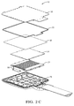
Fig. 2C is an exploded perspective view of the source transducer of the wireless power transfer system ofFig. 1 in accordance with one embodiment; -
Fig. 3A is a top perspective view of a capture transducer of the wireless power transfer system ofFig. 1 in accordance with one embodiment; -
Fig. 3B is a bottom perspective view of the capture transducer of the wireless power transfer system ofFig. 1 in accordance with one embodiment; -
Fig. 3C is an exploded perspective view of the capture transducer of the wireless power transfer system ofFig. 1 in accordance with one embodiment; -
Fig. 4A is a perspective view of a resonator assembly of the source transducer ofFigs. 2A-2C or the capture transducer ofFigs. 3A-3C in accordance with one embodiment; -
Fig. 4B is an exploded perspective view of a resonator assembly of the source transducer ofFigs. 2A-2C or the capture transducer ofFigs. 3A-3C in accordance with one embodiment; and -
Fig. 5 is a flowchart of a method of assembling the source transducer ofFigs. 2A-2C or the capture transducer ofFigs. 3A-3C in accordance with one embodiment. -
Fig. 1 illustrates a non-limiting example of a wirelesspower transfer system 10 that includes two transducers that is suited for wirelessly charging an electric vehicle. Thefirst transducer 12 is asource transducer 12 that is coupled to anelectrical power supply 14, such as an electric vehicle battery charger. Thesecond transducer 16 is acapture transducer 16 that is coupled to anelectrical load 18, such as a battery pack of an electric or hybridelectric vehicle 20. As shown inFig. 1 , thesource transducer 12 is disposed on theparking surface 22 of a parking lot and thecapture transducer 16 is attached to thevehicle 20. Thesource transducer 12 converts electrical energy from theelectrical power supply 14 to magnetic energy that is transmitted to thecapture transducer 16. Thecapture transducer 16 then converts the magnetic energy to electrical energy that is supplied to theelectrical load 18. - A non-limiting example of a
source transducer 12 is illustrated inFigs. 2A-2C Thesource transducer 12 includes asource resonator 24 contained within asource transducer housing 26. The source transducer housing26 includes asource transducer cover 28, asource transducer seal 30, and sourcetransducer mounting plate 32. - A non-limiting example of a
capture transducer 16 is illustrated inFigs. 3A-3C . Thecapture transducer 16 includes acapture resonator 24 contained within acapture transducer housing 34. Thecapture transducer housing 34 includes acapture transducer cover 36, acapture transducer seal 38, and a capturetransducer mounting plate 40. Differences between thesource transducer housing 26 and thecapture transducer housing 34 are driven by the different operating environments and mounting requirements of eachtransducer housing source resonator 24 and thecapture resonator 24 mounted within thetransducer housings identical resonator assemblies 24 may be used interchangeably as thesource resonator 24 or thecapture resonator 24. - The transducer covers 28, 36 are preferably formed of a non-conductive material, such as polypropylene (PP) plastic so that they do not affect the magnetic field between the source and capture
resonators 24. The transducer covers 28, 36 may be fabricated using injection molding, sheet forming, or other plastic fabrication methods well known to those skilled in the art. The transducer covers 28, 36 define a cavity that is configured to hold theresonator assembly 24 as well as other components of thetransducer plates environmental seals transducer cover plate transducer housing resonator assembly 24 and the other components contained within thetransducer housing plates plates plates transducer housings transducers vehicle 20 or theparking surface 22. The mountingplates plate transducer transducer cover transducer housing - A non-limiting example of a
resonator assembly 24 is illustrated inFigs. 4A and 4B . Theresonator assembly 24 includes a generally planar carrier-winder assembly 42, hereinafter referred to as the carrier-winder 42 that has two substantially identical carrier-winder halves 44. The carrier-winder 42 has a generally rectangular shape. Each carrier-winder half 44 defines acore retaining pocket 46 in the interior portion of the carrier-winder half 44 and an outercoil retaining surface 48 on the exterior portion of the carrier-winder half 44. As used herein, interior and exterior portion refer to the interior and exterior as the carrier-winder halves 44 are oriented in the carrier-winder 42. The core retaining pockets 46 define a cavity in the interior portion of the carrier-winder 42. The features of the carrier-winder halves 44, such as the core retaining pockets 46, thecoil retaining surface 48, and other features are symmetrical so that these features align when two carrier-winder halves 44 are joined. The carrier-winder halves 44 are attached to one another by treaded fasteners (not shown). However, other methods of fastening the carrier-winder halves 44, such as adhesives, rivets, or heat staking may alternatively be employed. The carrier-winder 42 is formed of a dielectric material, such as polybutylene terephthalate (PBT) or polyethylene terephthalate (PET) plastic. The carrier-winder halves 44 may be fabricated using injection molding or other plastic fabrication methods well known to those skilled in the art. - The resonator also includes a core tile 50 that is formed of a material that has a high magnetic permeability, such a ferrite, silicon steel, carbonyl iron, or vitreous metal material. The core tile 50 is contained in the cavity of the
core retaining pocket 46 in the carrier-winder 42. The core tile 50 is characterized as a substantially planar rectangular plate. The core tile 50 acts as a magnetic core to concentrate the lines of magnetic flux generated by theresonator assembly 24. The size of the core tile 50 that can be economically manufactured may be limited to a size that is smaller than the magnetic core required for the resonator. In that case, the carrier-winder 42 of eachresonator assembly 24 may contain a plurality ofsmaller core tiles 50A-50F. In order to accommodate a plurality of core tiles50A-50F, the carrier-winder halves 44 may define a plurality of core retaining pockets 46. - The resonator further includes a
wire coil 52 that is wound around thecoil retaining surface 48 of each carrier-winder 42. The carrier-winder 42 serves as a bobbin for thewire coil 52. The wire forming thewire coil 52 is preferably an insulated stranded wire, commonly known in the art as Litz wire. Thewire coil 52 is formed of a copper or an aluminum material, although other conductive materials may be used. As used herein, copper may referrer to a copper-based alloy or elemental copper. The coil retaining source defines features, such as grooves, on the outer portion of the carrier-winder 42 that are configured to at least partially contain a portion of thewire coil 52 in order to help retain thewire coil 52 in place. Thewire coil 52 may be secured to the carrier-winder 42, for example by nylon wire cable ties (not shown). - The
resonator assembly 24 illustrated inFig. 4A has a generally planar rectangular shape. The rectangular shape provides asource transducer 12 and acapture transducer 16 that, in a vehicle application, provide adequate road clearance beneath thevehicle 20 and between the source and capturetransducers resonator assembly 24 may be envisioned having other shapes, such as a toroidal shape. - Returning to
Figs. 2C and3C , theresonator assemblies 24 are secured within the cavities of thetransducer housings resonator holders 54. Eachresonator holder 54 is secured to one of the transducer covers 28, 36 by treaded fasteners (not shown). However, other methods of fastening theresonator holder 54 to thetransducer cover resonator holder 54 used to secure thecapture resonator 24 within arecapture transducer housing 34 and theresonator holder 54 used to secure thesource resonator 24 within thesource transducer housing 26 are substantially identical and are interchangeable. Theresonator holders 54 are preferably formed of a non-conductive material, such as PBT or PET plastic so that they do not affect the magnetic field between the source and captureresonators 24. Theresonator holders 54 may be fabricated using injection molding or other plastic fabrication methods well known to those skilled in the art. - As illustrated in
Figs. 2C and3C , thesource transducer 12 and thecapture transducer 16 each include aground plate 56 that is configured to provide an electrical ground plane for the resonator. Theground plate 56 is preferably formed of a highly conductive material, such as copper. As shown inFig. 2C , the sourcetransducer ground plate 56 is secured to thesource transducer housing 26. As shown inFig. 3C , the capturetransducer ground plate 56 is secured to thecapture transducer housing 34. The source transducerground plate 56 and the capturetransducer ground plate 56 are substantially identical and are interchangeable. - As illustrated in
Figs. 2C and3C , thesource transducer 12 further includes a sourcetransducer tuning network 58 and thecapture transducer 16 contains a capturetransducer tuning network 60. The mechanical form factor of the sourcetransducer tuning network 58 and the capturetransducer tuning network 60 may be the same, however, the inductance value of the sourcetransducer tuning network 58 may be different than the inductance value of the capturetransducer tuning network 60 so that the resonant frequency of thesource resonator 24 and the resonant frequency thecapture resonator 24 may be separately tuned. The capturetransducer tuning network 60 and the sourcetransducer tuning network 58 may include a capacitor network as well as other electronic components, such as resistors and/or inductors (not shown), that are mounted on a printed circuit board that is fastened within therespective transducer housing - The dimensions of the carrier-
winder 42, the core tile 50, the gauge and number of turns of the wire in thewire coil 52 and the material used for thewire coil 52 and the core tile 50 are some of the factors that will determine the resonant frequency of theresonator assembly 24. The methods used to determine the resonant frequency or the source and captureresonators 24 are well known to those skilled in the art. - Fig. 6 illustrates a method 100 of assembling a
source transducer 12 or acapture transducer 16 for a wirelesspower transfer system 10. The method 100 is the same for assembling either the source or capturetransducers - In
step 110, PROVIDE PAIR OF CARRIER-WINDER HALVES, two carrier-winder halves 44 are provided. - In
step 112, PLACE CORE TILE WITHIN CORE RETAINING POCKET, a core tile 50 or a plurality ofcore tiles 50A-50F is placed in thecore retaining pocket 46 of one of the carrier-winder halves 44. - In
step 114, ATTACH CARRIER-WINDER HALVES TO EACH OTHER, one half 44 of the carrier-winder 42 is attached to the other half 44 of the carrier-winder 42 using threaded fasteners or other fastening means, thereby at least partially enclosing the core tile 50 within the carrier-winder 42. - In
step 116, FORM WIRE COIL BY WRAPPING WIRE ABOUT CARRIER-WINDER, thewire coil 52 is formed by wrapping a predetermined length of Litz wire several times about thecoil retaining surface 48 of the carrier-winder 42. The wire is inserted into grooves defined by thecoil retaining surface 48 in order to provide proper spacing between the turns of thewire coil 52. Thewire coil 52 may be attached to the carrier-winder 42 using nylon cable ties, adhesive such as hot melt glue, or other alternative means. - In
step 118, PROVIDE TRANSDUCER COVER, atransducer cover - In
step 120, PLACE RESONATOR ASSEMBLY WITHIN TRANSDUCER COVER, the assembledresonator 24 is placed within the cavity of thetransducer cover - In
step 122, ATTACH RESONATOR ASSEMBLY TO TRANSDUCER COVER WITH RESONATOR HOLDER, theresonator assembly 24 is attached to thetransducer cover resonator holder 54 over theresonator assembly 24 and fastening theresonator holder 54 to thetransducer cover - In
step 124, ATTACH RESONATOR TUNING NETWORK TO TRANSDUCER COVER, a sourcetransducer tuning network 58 or a capturetransducer tuning network 60 is placed with the cavity of thetransducer cover transducer cover wire coil 52 are connected to the sourcetransducer tuning network 58 or the capturetransducer tuning network 60. Wires used for connecting thesource transducer 12 to theelectrical power supply 14 may also be connected to the sourcetransducer tuning network 58 and wires used for connecting thecapture transducer 16 to theelectrical load 18 may also be connected to the capturetransducer tuning network 60 and routed through a portal (not shown) defined in thetransducer cover - In
step 126, PLACE GROUND PLATE OVER RESONATOR HOLDER, theground plate 56 is placed over theresonator holder 54 within thetransducer cover 28 and theseal transducer cover - In
step 128, ATTACH MOUNTING PLATE TO TRANSDUCER COVER, the mountingplate transducer cover seal plate transducer cover - Accordingly, a wireless
power transfer system 10 having substantially identical and interchangeable source and captureresonator assemblies 24 is provided. Thesystem 10 provides the benefit of reduced manufacturing costs because both thesource transducer 12 and thecapture transducer 16 sharecommon resonator assemblies 24,resonator holders 54, andground plates 56. Only thetransducer housings 26, 34 (transducer covers 28, 36, seals 30, 38, and mountingplates 32, 40) andresonator tuning networks source transducer 12 and thecapture transducer 16. Therectangular resonator assembly 24 also reduces manufacturing cost compared to toroidal resonator assemblies since it is easier to wrap the wire coil around the rectangular carrier-winder 42 than a toroidal carrier winder because the wire coil does not need to be threaded through a hole in the center of the carrier winder each time the wire coil is wrapped around the toroidal carrier winder nor does radial spacing need to be maintained between the windings of the wire coil. A method 100 of assembling asource transducer 12 andcapture transducer 16 is also provided. The method 100 is a common process for both thesource transducer 12 and thecapture transducer 16. The process uses thetransducer cover transducer - The use of the terms first, second, etc. does not denote any order of importance, but rather the terms first, second, etc. are used to distinguish one element from another. Furthermore, the use of the terms a, an, etc. do not denote a limitation of quantity, but rather denote the presence of at least one of the referenced items.
Claims (10)
- A wireless power transfer system (10) that transmits electrical power from an electrical power source to an electrical load (18) using a source resonator (24) and a capture resonator (24) that are inductively coupled, characterized in that each resonator (24) comprises:an insulative split carrier-winder assembly (42) having two substantially identical halves (44A, 44B), each half (44) defining an interior core retaining pocket (46) and an outer coil retaining surface (48);a core tile (50) formed of a material having high magnetic permeability and contained in the interior core retaining pocket (46) of each carrier-winder assembly (42), anda wire coil (52) wound around the outer coil retaining surface (48) of each carrier-winder assembly (42), wherein two substantially identical resonators (24) may be used interchangeably as the source resonator (24) or the capture resonator (24).
- Wireless power transfer system (10) according to claim 1, further comprising:a first housing (26) configured to contain the source resonator (24);a first resonator holder (54) configured to secure the source resonator (24) within the first housing (26);a second housing (34) configured to contain the capture resonator (24); anda second resonator holder (54) configured to secure the capture resonator (24) within the second housing (34), wherein the first resonator holder (54) and the second resonator holder (54) are substantially identical and are interchangeable.
- Wireless power transfer system (10) according to claim 2, further comprising:a first ground plate (56) configured to provide an electrical ground plane for the source resonator (24) and configured to be secured to the first housing (26); anda second ground plate (56) configured to provide an electrical ground plane for the capture resonator (24) and configured to be secured to the second housing (34), wherein the first ground plate (56) and the second ground plate (56) are substantially identical and are interchangeable.
- Wireless power transfer system (10) according to claim 3, wherein the first ground plate (56) and the second ground plate (56) are formed of a copper material.
- Wireless power transfer system (10) according to any one of claims 2 to 4, wherein said first housing (26) contains a source resonator tuning network (58), wherein said second housing (34) contains a capture resonator tuning network (60), and wherein the inductance values of the source resonator tuning network (58) are different than the inductance values of the capture resonator tuning network (60) whereby the resonant frequency of the source resonator (24) and the capture resonator (24) may be separately tuned.
- Wireless power transfer system (10) according to any one of the preceding claims, wherein the core tile (50) is characterized as a substantially planar rectangular plate.
- Wireless power transfer system (10) according to any one of the preceding claims, wherein the core tile (50) is formed of a ferrite material.
- Wireless power transfer system (10) according to any one of the preceding claims, wherein the outer coil retaining surface (48) defines a plurality of grooves configured to at least partially contain the wire coil (52).
- The wireless power transfer system (10) according to any one of the preceding claims, wherein each resonator (24) comprises a plurality of core tiles (50A-50F).
- The wireless power transfer system (10) according to any one of the preceding claims, wherein each half of said carrier-winder assembly (42) defines a plurality of core retaining pockets (46).
Applications Claiming Priority (1)
| Application Number | Priority Date | Filing Date | Title |
|---|---|---|---|
| US13/874,823 US9472339B2 (en) | 2013-05-01 | 2013-05-01 | Wireless power transfer system transducers having interchangeable source resonator and capture resonator |
Publications (3)
| Publication Number | Publication Date |
|---|---|
| EP2800111A2 true EP2800111A2 (en) | 2014-11-05 |
| EP2800111A3 EP2800111A3 (en) | 2015-01-07 |
| EP2800111B1 EP2800111B1 (en) | 2016-09-07 |
Family
ID=50639266
Family Applications (1)
| Application Number | Title | Priority Date | Filing Date |
|---|---|---|---|
| EP14165669.4A Not-in-force EP2800111B1 (en) | 2013-05-01 | 2014-04-23 | Wireless power transfer system transducers having interchangeable source resonator and capture resonator |
Country Status (3)
| Country | Link |
|---|---|
| US (1) | US9472339B2 (en) |
| EP (1) | EP2800111B1 (en) |
| JP (1) | JP2014220499A (en) |
Cited By (3)
| Publication number | Priority date | Publication date | Assignee | Title |
|---|---|---|---|---|
| WO2018033298A1 (en) * | 2016-08-16 | 2018-02-22 | Audi Ag | Energy storage device for a motor vehicle, and motor vehicle |
| CN108382220A (en) * | 2018-01-26 | 2018-08-10 | 清华大学 | Wireless charging magnetic coupler between the electronic automobile-used traveling of one kind |
| CN109109677A (en) * | 2017-06-22 | 2019-01-01 | 本田技研工业株式会社 | Non-contact electric power transmission system |
Families Citing this family (7)
| Publication number | Priority date | Publication date | Assignee | Title |
|---|---|---|---|---|
| JP2015015452A (en) * | 2013-06-06 | 2015-01-22 | Tdk株式会社 | Coil device for wireless power transmission |
| EP2992776B1 (en) * | 2014-09-04 | 2019-11-06 | WITS Co., Ltd. | Case and apparatus including the same |
| CN104505918A (en) * | 2015-01-16 | 2015-04-08 | 蔡乌力吉 | Parking lot |
| CN104505914A (en) * | 2015-01-16 | 2015-04-08 | 蔡乌力吉 | Parking lot |
| WO2017029713A1 (en) * | 2015-08-18 | 2017-02-23 | 株式会社 東芝 | Inductor and wireless power transmission device |
| CN107512182A (en) * | 2017-07-12 | 2017-12-26 | 江苏财经职业技术学院 | High security electric automobile wireless charging cabinet |
| DE102023116108A1 (en) * | 2023-06-20 | 2024-12-24 | Magnetec Gmbh | Transmitting and/or receiving unit, charging device, energy transmission unit, motor vehicle, method for producing a transmitting and/or receiving unit, use of a metallic glass material and use of magnetic field sensitive particles |
Family Cites Families (17)
| Publication number | Priority date | Publication date | Assignee | Title |
|---|---|---|---|---|
| US7263388B2 (en) | 2001-06-29 | 2007-08-28 | Nokia Corporation | Charging system for portable equipment |
| KR100898463B1 (en) | 2003-02-04 | 2009-05-21 | 액세스 비지니스 그룹 인터내셔날 엘엘씨 | Inductive coil assembly |
| US20070131505A1 (en) | 2005-07-16 | 2007-06-14 | Kim Bryan H J | Magnetic Induction Charging System for Vehicles |
| US8169185B2 (en) | 2006-01-31 | 2012-05-01 | Mojo Mobility, Inc. | System and method for inductive charging of portable devices |
| US8304935B2 (en) | 2008-09-27 | 2012-11-06 | Witricity Corporation | Wireless energy transfer using field shaping to reduce loss |
| US20120313742A1 (en) | 2008-09-27 | 2012-12-13 | Witricity Corporation | Compact resonators for wireless energy transfer in vehicle applications |
| US9105959B2 (en) * | 2008-09-27 | 2015-08-11 | Witricity Corporation | Resonator enclosure |
| US9577436B2 (en) | 2008-09-27 | 2017-02-21 | Witricity Corporation | Wireless energy transfer for implantable devices |
| WO2010036980A1 (en) | 2008-09-27 | 2010-04-01 | Witricity Corporation | Wireless energy transfer systems |
| KR101455825B1 (en) | 2008-12-18 | 2014-10-30 | 삼성전자 주식회사 | Resonator for wireless power transmission |
| KR101948276B1 (en) | 2009-02-05 | 2019-02-14 | 오클랜드 유니서비시즈 리미티드 | Inductive power transfer apparatus |
| US9178369B2 (en) | 2011-01-18 | 2015-11-03 | Mojo Mobility, Inc. | Systems and methods for providing positioning freedom, and support of different voltages, protocols, and power levels in a wireless power system |
| WO2012099170A1 (en) | 2011-01-19 | 2012-07-26 | 株式会社 テクノバ | Contactless power transfer system |
| CA2844062C (en) | 2011-08-04 | 2017-03-28 | Witricity Corporation | Tunable wireless power architectures |
| CN104335450A (en) | 2012-05-09 | 2015-02-04 | 丰田自动车株式会社 | Vehicle capable of contact-free power reception |
| KR101697418B1 (en) * | 2012-05-09 | 2017-01-17 | 도요타지도샤가부시키가이샤 | Vehicle |
| KR20150003894A (en) | 2012-06-04 | 2015-01-09 | 도요타지도샤가부시키가이샤 | Power reception device, power transmission device, and vehicle |
-
2013
- 2013-05-01 US US13/874,823 patent/US9472339B2/en not_active Expired - Fee Related
-
2014
- 2014-04-23 EP EP14165669.4A patent/EP2800111B1/en not_active Not-in-force
- 2014-04-28 JP JP2014092309A patent/JP2014220499A/en not_active Withdrawn
Non-Patent Citations (1)
| Title |
|---|
| None |
Cited By (4)
| Publication number | Priority date | Publication date | Assignee | Title |
|---|---|---|---|---|
| WO2018033298A1 (en) * | 2016-08-16 | 2018-02-22 | Audi Ag | Energy storage device for a motor vehicle, and motor vehicle |
| CN109109677A (en) * | 2017-06-22 | 2019-01-01 | 本田技研工业株式会社 | Non-contact electric power transmission system |
| CN109109677B (en) * | 2017-06-22 | 2021-10-01 | 本田技研工业株式会社 | Contactless Electric Power Transmission System |
| CN108382220A (en) * | 2018-01-26 | 2018-08-10 | 清华大学 | Wireless charging magnetic coupler between the electronic automobile-used traveling of one kind |
Also Published As
| Publication number | Publication date |
|---|---|
| US20140327317A1 (en) | 2014-11-06 |
| EP2800111A3 (en) | 2015-01-07 |
| US9472339B2 (en) | 2016-10-18 |
| JP2014220499A (en) | 2014-11-20 |
| EP2800111B1 (en) | 2016-09-07 |
Similar Documents
| Publication | Publication Date | Title |
|---|---|---|
| EP2800111B1 (en) | Wireless power transfer system transducers having interchangeable source resonator and capture resonator | |
| JP5293851B2 (en) | Coil unit and non-contact power supply system | |
| CN101867203B (en) | Inductive chargers and inductive charging systems for portable electronic devices | |
| US11232900B2 (en) | Device for a wireless power transfer system | |
| US10686333B2 (en) | Method for manufacturing wireless power-transmitting device, and resonator | |
| CN111527666B (en) | wireless power transmission device | |
| US20130249303A1 (en) | Magnetically permeable structures | |
| US9947461B2 (en) | Reactor | |
| US11217387B2 (en) | Device for a wireless power transfer system for a vehicle | |
| CN107275063A (en) | Power coil unit, wireless power supply and Contactless power transmission device | |
| KR20140144699A (en) | Wireless power transfer apparatus and method of manufacture | |
| US20150348696A1 (en) | Induction charging coil device | |
| US9960745B2 (en) | Noise filter and wire harness | |
| CN106451817A (en) | Power transmission apparatus and power reception apparatus | |
| US10177603B2 (en) | Coil unit and power supply system including the same | |
| US11211189B2 (en) | Coil device | |
| CN104810904B (en) | Secondary coil module | |
| CN105874678A (en) | Inductive charging device | |
| US20160159227A1 (en) | Wireless charging device for charging a battery of a vehicle | |
| JP6285810B2 (en) | Coil unit in non-contact power feeder | |
| KR102408534B1 (en) | Device for inductively charging an electrical storage unit | |
| KR101589609B1 (en) | Wireless Electric Power Supply Apparatus | |
| JP6225551B2 (en) | Resonator | |
| KR101693538B1 (en) | wireless charging transmission module for car |
Legal Events
| Date | Code | Title | Description |
|---|---|---|---|
| PUAI | Public reference made under article 153(3) epc to a published international application that has entered the european phase |
Free format text: ORIGINAL CODE: 0009012 |
|
| 17P | Request for examination filed |
Effective date: 20140423 |
|
| AK | Designated contracting states |
Kind code of ref document: A2 Designated state(s): AL AT BE BG CH CY CZ DE DK EE ES FI FR GB GR HR HU IE IS IT LI LT LU LV MC MK MT NL NO PL PT RO RS SE SI SK SM TR |
|
| AX | Request for extension of the european patent |
Extension state: BA ME |
|
| PUAL | Search report despatched |
Free format text: ORIGINAL CODE: 0009013 |
|
| AK | Designated contracting states |
Kind code of ref document: A3 Designated state(s): AL AT BE BG CH CY CZ DE DK EE ES FI FR GB GR HR HU IE IS IT LI LT LU LV MC MK MT NL NO PL PT RO RS SE SI SK SM TR |
|
| AX | Request for extension of the european patent |
Extension state: BA ME |
|
| RIC1 | Information provided on ipc code assigned before grant |
Ipc: H01F 27/32 20060101ALI20141201BHEP Ipc: B60L 11/18 20060101ALI20141201BHEP Ipc: H01F 38/14 20060101AFI20141201BHEP Ipc: H01F 27/28 20060101ALI20141201BHEP |
|
| R17P | Request for examination filed (corrected) |
Effective date: 20150707 |
|
| RBV | Designated contracting states (corrected) |
Designated state(s): AL AT BE BG CH CY CZ DE DK EE ES FI FR GB GR HR HU IE IS IT LI LT LU LV MC MK MT NL NO PL PT RO RS SE SI SK SM TR |
|
| 17Q | First examination report despatched |
Effective date: 20150831 |
|
| GRAP | Despatch of communication of intention to grant a patent |
Free format text: ORIGINAL CODE: EPIDOSNIGR1 |
|
| INTG | Intention to grant announced |
Effective date: 20160122 |
|
| GRAS | Grant fee paid |
Free format text: ORIGINAL CODE: EPIDOSNIGR3 |
|
| GRAR | Information related to intention to grant a patent recorded |
Free format text: ORIGINAL CODE: EPIDOSNIGR71 |
|
| GRAA | (expected) grant |
Free format text: ORIGINAL CODE: 0009210 |
|
| INTG | Intention to grant announced |
Effective date: 20160722 |
|
| AK | Designated contracting states |
Kind code of ref document: B1 Designated state(s): AL AT BE BG CH CY CZ DE DK EE ES FI FR GB GR HR HU IE IS IT LI LT LU LV MC MK MT NL NO PL PT RO RS SE SI SK SM TR |
|
| REG | Reference to a national code |
Ref country code: GB Ref legal event code: FG4D |
|
| REG | Reference to a national code |
Ref country code: CH Ref legal event code: EP |
|
| REG | Reference to a national code |
Ref country code: IE Ref legal event code: FG4D |
|
| REG | Reference to a national code |
Ref country code: AT Ref legal event code: REF Ref document number: 827508 Country of ref document: AT Kind code of ref document: T Effective date: 20161015 |
|
| REG | Reference to a national code |
Ref country code: DE Ref legal event code: R096 Ref document number: 602014003460 Country of ref document: DE |
|
| REG | Reference to a national code |
Ref country code: LT Ref legal event code: MG4D |
|
| REG | Reference to a national code |
Ref country code: NL Ref legal event code: MP Effective date: 20160907 |
|
| PG25 | Lapsed in a contracting state [announced via postgrant information from national office to epo] |
Ref country code: FI Free format text: LAPSE BECAUSE OF FAILURE TO SUBMIT A TRANSLATION OF THE DESCRIPTION OR TO PAY THE FEE WITHIN THE PRESCRIBED TIME-LIMIT Effective date: 20160907 Ref country code: HR Free format text: LAPSE BECAUSE OF FAILURE TO SUBMIT A TRANSLATION OF THE DESCRIPTION OR TO PAY THE FEE WITHIN THE PRESCRIBED TIME-LIMIT Effective date: 20160907 Ref country code: LT Free format text: LAPSE BECAUSE OF FAILURE TO SUBMIT A TRANSLATION OF THE DESCRIPTION OR TO PAY THE FEE WITHIN THE PRESCRIBED TIME-LIMIT Effective date: 20160907 Ref country code: RS Free format text: LAPSE BECAUSE OF FAILURE TO SUBMIT A TRANSLATION OF THE DESCRIPTION OR TO PAY THE FEE WITHIN THE PRESCRIBED TIME-LIMIT Effective date: 20160907 Ref country code: NO Free format text: LAPSE BECAUSE OF FAILURE TO SUBMIT A TRANSLATION OF THE DESCRIPTION OR TO PAY THE FEE WITHIN THE PRESCRIBED TIME-LIMIT Effective date: 20161207 |
|
| REG | Reference to a national code |
Ref country code: AT Ref legal event code: MK05 Ref document number: 827508 Country of ref document: AT Kind code of ref document: T Effective date: 20160907 |
|
| PG25 | Lapsed in a contracting state [announced via postgrant information from national office to epo] |
Ref country code: SE Free format text: LAPSE BECAUSE OF FAILURE TO SUBMIT A TRANSLATION OF THE DESCRIPTION OR TO PAY THE FEE WITHIN THE PRESCRIBED TIME-LIMIT Effective date: 20160907 Ref country code: LV Free format text: LAPSE BECAUSE OF FAILURE TO SUBMIT A TRANSLATION OF THE DESCRIPTION OR TO PAY THE FEE WITHIN THE PRESCRIBED TIME-LIMIT Effective date: 20160907 Ref country code: GR Free format text: LAPSE BECAUSE OF FAILURE TO SUBMIT A TRANSLATION OF THE DESCRIPTION OR TO PAY THE FEE WITHIN THE PRESCRIBED TIME-LIMIT Effective date: 20161208 Ref country code: ES Free format text: LAPSE BECAUSE OF FAILURE TO SUBMIT A TRANSLATION OF THE DESCRIPTION OR TO PAY THE FEE WITHIN THE PRESCRIBED TIME-LIMIT Effective date: 20160907 Ref country code: NL Free format text: LAPSE BECAUSE OF FAILURE TO SUBMIT A TRANSLATION OF THE DESCRIPTION OR TO PAY THE FEE WITHIN THE PRESCRIBED TIME-LIMIT Effective date: 20160907 |
|
| REG | Reference to a national code |
Ref country code: FR Ref legal event code: PLFP Year of fee payment: 4 |
|
| PG25 | Lapsed in a contracting state [announced via postgrant information from national office to epo] |
Ref country code: RO Free format text: LAPSE BECAUSE OF FAILURE TO SUBMIT A TRANSLATION OF THE DESCRIPTION OR TO PAY THE FEE WITHIN THE PRESCRIBED TIME-LIMIT Effective date: 20160907 Ref country code: EE Free format text: LAPSE BECAUSE OF FAILURE TO SUBMIT A TRANSLATION OF THE DESCRIPTION OR TO PAY THE FEE WITHIN THE PRESCRIBED TIME-LIMIT Effective date: 20160907 |
|
| PG25 | Lapsed in a contracting state [announced via postgrant information from national office to epo] |
Ref country code: SM Free format text: LAPSE BECAUSE OF FAILURE TO SUBMIT A TRANSLATION OF THE DESCRIPTION OR TO PAY THE FEE WITHIN THE PRESCRIBED TIME-LIMIT Effective date: 20160907 Ref country code: AT Free format text: LAPSE BECAUSE OF FAILURE TO SUBMIT A TRANSLATION OF THE DESCRIPTION OR TO PAY THE FEE WITHIN THE PRESCRIBED TIME-LIMIT Effective date: 20160907 Ref country code: PT Free format text: LAPSE BECAUSE OF FAILURE TO SUBMIT A TRANSLATION OF THE DESCRIPTION OR TO PAY THE FEE WITHIN THE PRESCRIBED TIME-LIMIT Effective date: 20170109 Ref country code: SK Free format text: LAPSE BECAUSE OF FAILURE TO SUBMIT A TRANSLATION OF THE DESCRIPTION OR TO PAY THE FEE WITHIN THE PRESCRIBED TIME-LIMIT Effective date: 20160907 Ref country code: BG Free format text: LAPSE BECAUSE OF FAILURE TO SUBMIT A TRANSLATION OF THE DESCRIPTION OR TO PAY THE FEE WITHIN THE PRESCRIBED TIME-LIMIT Effective date: 20161207 Ref country code: BE Free format text: LAPSE BECAUSE OF FAILURE TO SUBMIT A TRANSLATION OF THE DESCRIPTION OR TO PAY THE FEE WITHIN THE PRESCRIBED TIME-LIMIT Effective date: 20160907 Ref country code: IS Free format text: LAPSE BECAUSE OF FAILURE TO SUBMIT A TRANSLATION OF THE DESCRIPTION OR TO PAY THE FEE WITHIN THE PRESCRIBED TIME-LIMIT Effective date: 20170107 Ref country code: CZ Free format text: LAPSE BECAUSE OF FAILURE TO SUBMIT A TRANSLATION OF THE DESCRIPTION OR TO PAY THE FEE WITHIN THE PRESCRIBED TIME-LIMIT Effective date: 20160907 Ref country code: PL Free format text: LAPSE BECAUSE OF FAILURE TO SUBMIT A TRANSLATION OF THE DESCRIPTION OR TO PAY THE FEE WITHIN THE PRESCRIBED TIME-LIMIT Effective date: 20160907 |
|
| REG | Reference to a national code |
Ref country code: DE Ref legal event code: R097 Ref document number: 602014003460 Country of ref document: DE |
|
| PG25 | Lapsed in a contracting state [announced via postgrant information from national office to epo] |
Ref country code: IT Free format text: LAPSE BECAUSE OF FAILURE TO SUBMIT A TRANSLATION OF THE DESCRIPTION OR TO PAY THE FEE WITHIN THE PRESCRIBED TIME-LIMIT Effective date: 20160907 |
|
| PLBE | No opposition filed within time limit |
Free format text: ORIGINAL CODE: 0009261 |
|
| STAA | Information on the status of an ep patent application or granted ep patent |
Free format text: STATUS: NO OPPOSITION FILED WITHIN TIME LIMIT |
|
| PG25 | Lapsed in a contracting state [announced via postgrant information from national office to epo] |
Ref country code: DK Free format text: LAPSE BECAUSE OF FAILURE TO SUBMIT A TRANSLATION OF THE DESCRIPTION OR TO PAY THE FEE WITHIN THE PRESCRIBED TIME-LIMIT Effective date: 20160907 |
|
| PGFP | Annual fee paid to national office [announced via postgrant information from national office to epo] |
Ref country code: DE Payment date: 20170427 Year of fee payment: 4 Ref country code: FR Payment date: 20170426 Year of fee payment: 4 |
|
| 26N | No opposition filed |
Effective date: 20170608 |
|
| PG25 | Lapsed in a contracting state [announced via postgrant information from national office to epo] |
Ref country code: SI Free format text: LAPSE BECAUSE OF FAILURE TO SUBMIT A TRANSLATION OF THE DESCRIPTION OR TO PAY THE FEE WITHIN THE PRESCRIBED TIME-LIMIT Effective date: 20160907 |
|
| REG | Reference to a national code |
Ref country code: CH Ref legal event code: PL |
|
| REG | Reference to a national code |
Ref country code: IE Ref legal event code: MM4A |
|
| PG25 | Lapsed in a contracting state [announced via postgrant information from national office to epo] |
Ref country code: MC Free format text: LAPSE BECAUSE OF FAILURE TO SUBMIT A TRANSLATION OF THE DESCRIPTION OR TO PAY THE FEE WITHIN THE PRESCRIBED TIME-LIMIT Effective date: 20160907 |
|
| PG25 | Lapsed in a contracting state [announced via postgrant information from national office to epo] |
Ref country code: LU Free format text: LAPSE BECAUSE OF NON-PAYMENT OF DUE FEES Effective date: 20170423 Ref country code: LI Free format text: LAPSE BECAUSE OF NON-PAYMENT OF DUE FEES Effective date: 20170430 Ref country code: CH Free format text: LAPSE BECAUSE OF NON-PAYMENT OF DUE FEES Effective date: 20170430 |
|
| PG25 | Lapsed in a contracting state [announced via postgrant information from national office to epo] |
Ref country code: IE Free format text: LAPSE BECAUSE OF NON-PAYMENT OF DUE FEES Effective date: 20170423 |
|
| PG25 | Lapsed in a contracting state [announced via postgrant information from national office to epo] |
Ref country code: MT Free format text: LAPSE BECAUSE OF NON-PAYMENT OF DUE FEES Effective date: 20170423 |
|
| PG25 | Lapsed in a contracting state [announced via postgrant information from national office to epo] |
Ref country code: AL Free format text: LAPSE BECAUSE OF FAILURE TO SUBMIT A TRANSLATION OF THE DESCRIPTION OR TO PAY THE FEE WITHIN THE PRESCRIBED TIME-LIMIT Effective date: 20160907 |
|
| REG | Reference to a national code |
Ref country code: DE Ref legal event code: R119 Ref document number: 602014003460 Country of ref document: DE |
|
| GBPC | Gb: european patent ceased through non-payment of renewal fee |
Effective date: 20180423 |
|
| PG25 | Lapsed in a contracting state [announced via postgrant information from national office to epo] |
Ref country code: DE Free format text: LAPSE BECAUSE OF NON-PAYMENT OF DUE FEES Effective date: 20181101 |
|
| PG25 | Lapsed in a contracting state [announced via postgrant information from national office to epo] |
Ref country code: GB Free format text: LAPSE BECAUSE OF NON-PAYMENT OF DUE FEES Effective date: 20180423 |
|
| PG25 | Lapsed in a contracting state [announced via postgrant information from national office to epo] |
Ref country code: FR Free format text: LAPSE BECAUSE OF NON-PAYMENT OF DUE FEES Effective date: 20180430 |
|
| PG25 | Lapsed in a contracting state [announced via postgrant information from national office to epo] |
Ref country code: HU Free format text: LAPSE BECAUSE OF FAILURE TO SUBMIT A TRANSLATION OF THE DESCRIPTION OR TO PAY THE FEE WITHIN THE PRESCRIBED TIME-LIMIT; INVALID AB INITIO Effective date: 20140423 |
|
| PG25 | Lapsed in a contracting state [announced via postgrant information from national office to epo] |
Ref country code: CY Free format text: LAPSE BECAUSE OF FAILURE TO SUBMIT A TRANSLATION OF THE DESCRIPTION OR TO PAY THE FEE WITHIN THE PRESCRIBED TIME-LIMIT Effective date: 20160907 |
|
| PG25 | Lapsed in a contracting state [announced via postgrant information from national office to epo] |
Ref country code: MK Free format text: LAPSE BECAUSE OF FAILURE TO SUBMIT A TRANSLATION OF THE DESCRIPTION OR TO PAY THE FEE WITHIN THE PRESCRIBED TIME-LIMIT Effective date: 20160907 |
|
| PG25 | Lapsed in a contracting state [announced via postgrant information from national office to epo] |
Ref country code: TR Free format text: LAPSE BECAUSE OF FAILURE TO SUBMIT A TRANSLATION OF THE DESCRIPTION OR TO PAY THE FEE WITHIN THE PRESCRIBED TIME-LIMIT Effective date: 20160907 |