EP2800079B1 - Home appliance, home appliance system, and method of controlling the same - Google Patents
Home appliance, home appliance system, and method of controlling the same Download PDFInfo
- Publication number
- EP2800079B1 EP2800079B1 EP14163847.8A EP14163847A EP2800079B1 EP 2800079 B1 EP2800079 B1 EP 2800079B1 EP 14163847 A EP14163847 A EP 14163847A EP 2800079 B1 EP2800079 B1 EP 2800079B1
- Authority
- EP
- European Patent Office
- Prior art keywords
- home appliance
- terminal
- network
- tag unit
- unit
- Prior art date
- Legal status (The legal status is an assumption and is not a legal conclusion. Google has not performed a legal analysis and makes no representation as to the accuracy of the status listed.)
- Not-in-force
Links
Images







Classifications
-
- G—PHYSICS
- G06—COMPUTING OR CALCULATING; COUNTING
- G06K—GRAPHICAL DATA READING; PRESENTATION OF DATA; RECORD CARRIERS; HANDLING RECORD CARRIERS
- G06K17/00—Methods or arrangements for effecting co-operative working between equipments covered by two or more of main groups G06K1/00 - G06K15/00, e.g. automatic card files incorporating conveying and reading operations
-
- G—PHYSICS
- G08—SIGNALLING
- G08C—TRANSMISSION SYSTEMS FOR MEASURED VALUES, CONTROL OR SIMILAR SIGNALS
- G08C13/00—Arrangements for influencing the relationship between signals at input and output, e.g. differentiating, delaying
- G08C13/02—Arrangements for influencing the relationship between signals at input and output, e.g. differentiating, delaying to yield a signal which is a function of two or more signals, e.g. sum or product
-
- G—PHYSICS
- G08—SIGNALLING
- G08C—TRANSMISSION SYSTEMS FOR MEASURED VALUES, CONTROL OR SIMILAR SIGNALS
- G08C17/00—Arrangements for transmitting signals characterised by the use of a wireless electrical link
- G08C17/02—Arrangements for transmitting signals characterised by the use of a wireless electrical link using a radio link
-
- H—ELECTRICITY
- H04—ELECTRIC COMMUNICATION TECHNIQUE
- H04B—TRANSMISSION
- H04B5/00—Near-field transmission systems, e.g. inductive or capacitive transmission systems
- H04B5/20—Near-field transmission systems, e.g. inductive or capacitive transmission systems characterised by the transmission technique; characterised by the transmission medium
-
- H—ELECTRICITY
- H04—ELECTRIC COMMUNICATION TECHNIQUE
- H04B—TRANSMISSION
- H04B5/00—Near-field transmission systems, e.g. inductive or capacitive transmission systems
- H04B5/70—Near-field transmission systems, e.g. inductive or capacitive transmission systems specially adapted for specific purposes
-
- G—PHYSICS
- G08—SIGNALLING
- G08C—TRANSMISSION SYSTEMS FOR MEASURED VALUES, CONTROL OR SIMILAR SIGNALS
- G08C2201/00—Transmission systems of control signals via wireless link
- G08C2201/40—Remote control systems using repeaters, converters, gateways
- G08C2201/42—Transmitting or receiving remote control signals via a network
-
- G—PHYSICS
- G08—SIGNALLING
- G08C—TRANSMISSION SYSTEMS FOR MEASURED VALUES, CONTROL OR SIMILAR SIGNALS
- G08C2201/00—Transmission systems of control signals via wireless link
- G08C2201/50—Receiving or transmitting feedback, e.g. replies, status updates, acknowledgements, from the controlled devices
- G08C2201/51—Remote controlling of devices based on replies, status thereof
Definitions
- This disclosure relates to a home appliance, a home appliance system, and a method of controlling the home appliance and the home appliance system, and more particularly, to a home appliance, a home appliance system, and a method of controlling the home appliance and the home appliance system that change and control communication settings of the home appliance through data transmission and reception with a terminal.
- Document US 2010/156639 A1 discloses a home appliance according to the preamble of claim 1, wherein configuration data between a terminal and an electronic device are transferred.
- the electronic device stores the configuration data locally at a wireless receiver and a core processor interrogates the wireless receiver when the electronic device is powered up.
- Document US 2005/0037707 A1 discloses a wireless communication device including a passive radio frequency tag having a memory for receiving and storing initial configuration information utilized by the device.
- the initial configuration information is written to the wireless communication device without requiring that the device is fully assembled, operational, powered up, removed from packaging, etc..
- An RF controller transmits initial configuration information to the passive tag using an RF signal.
- US 2008/0204199 A1 discloses a method and system for remotely configuring and/or provisioning a device that is non-operational.
- This device may be an electronic device including at least one setting that can be programmatically or otherwise established or adjusted to configure and/or provision of the device for its operation.
- laundry processing devices include a washing machine, a dryer, and a washing machine having a dryer function.
- a washing machine In order to remove pollutants from the laundry such as clothes and bedding using water and detergent and a mechanical operation, a washing machine is a device that performs a process such as washing, rinsing, and dehydration. Such washing machines are classified into a top load type washing machine of rotating a drum in which the laundry is filled about a vertical axis and a front load type washing machine of rotating a drum in which the laundry is filled about a horizontal axis.
- the dryer is a device that dries the laundry to be dried by applying warm air to the laundry to be dried and that injects the laundry to be dried into a rotating drum and that dries the laundry by applying warm wind or cold wind into the drum.
- the washing machine having a dryer function has both a washing function and a dry function and is a device in which the laundry such as clothes is injected into a rotating drum, a desired function is selected and that performs washing or drying.
- a home appliance using a network is important.
- connection setting thereof is necessary, but a keyboard or an input device similar thereto may not be provided in an entire home appliance and thus a way of connecting the home appliance to the network is requested.
- a home appliance comprising a communication unit for transmitting and receiving data; a tag unit for performing Near Field Communication (NFC) with a terminal; and a controller configured to (i) store product information at the tag unit, (ii) receive data stored at the tag unit, (iii) change an operation setting, and (iv) control a operation state, wherein the controller is configured to determine network connection information that is stored at the tag unit, to set the network connection information in the communication unit, and to transmit and receive data through a predetermined network through the communication unit.
- NFC Near Field Communication
- a home appliance may include a display unit that outputs an operation setting and an operation state; a tag unit that performs Near Field Communication (NFC) with a terminal; and a controller that (i) stores product information at the tag unit, (ii) receives data stored at the tag unit, (iii) changes the operation setting, (iv) controls the operation state, and (v) outputs the changed operation setting to the display unit, where the controller determines network connection information that is stored at the tag unit, e.g. by the terminal, sets the network connection information, e.g. in a communication unit of the home appliance, and transmits and receives data through a predetermined network.
- data are received wirelessly through a communication unit of the home appliance.
- a home appliance having a tag unit for NFC, which is configured to store product information at the tag unit, and to be connected to a predetermined network according to network connection information stored at the tag unit.
- a home appliance system may include a terminal having Near Field Communication function, and a home appliance according to any of the herein described embodiments, wherein the terminal receives the product information stored at the tag unit when contacting the tag unit, stores the network connection information at the tag unit and stores the product information associated with the home appliance.
- a server that stores and manages data associated with a plurality of home appliances is also provided in the system.
- the tag unit may include a tag storage unit that stores at least one of the product information and the network connection information.
- the tag unit may include a transmitting and receiving unit that recognizes that the terminal contacts the tag unit and/or is within a predetermined distance to the tag unit.
- the controller may instruct the display unit to display a connection state, in response to the home appliance being connected to the network according to the network connection information.
- the controller may instruct the display unit to display an error message, in response to the home appliance not being connected to the network.
- the controller may transmit data associated with the home appliance according to a request received from the terminal and/or an external server.
- the controller may control operation of the home appliance according to a received control instruction in response to the home appliance being connected to the network through the communication unit.
- the controller may be configured to at least one of determining a state of the tag unit, receiving new data, and updating network connection information, a control program, and/or a control operation to correspond to new data, preferably in response to power of the home appliance being turned on.
- the controller may be configured to control an operation to correspond to new data, preferably in response to power of the home appliance being turned on.
- the tag unit may store data received from the terminal at the tag storage unit in response to the home appliance contacting the terminal, preferably independent of the home appliance being turned on.
- the tag unit may be detachably provided on the home appliance.
- a terminal having a Near Field Communication (NFC) function wherein the terminal (i) is configured to receive product information associated with a home appliance and stored at a tag unit when contacting the tag unit, (ii) to store network connection information at the tag unit, and (iii) to store the product information associated with the home appliance, e.g. at a server for storing and managing data associated with a plurality of home appliances.
- NFC Near Field Communication
- the home appliance may be any of the above described embodiments.
- the terminal may be configured according to any embodiments described below.
- a home appliance system is provided including the terminal and the home appliance.
- a home appliance system that includes a terminal having a Near Field Communication (NFC) function; a server that stores and manages data associated with a plurality of home appliances; and a home appliance that (i) has a tag unit for NFC, (ii) stores product information at the tag unit, and (iii) is connected to a predetermined network according to network connection information stored at the tag unit by the terminal, where the terminal (i) receives the product information stored at the tag unit when contacting the tag unit, (ii) stores the network connection information at the tag unit, and (iii) stores the product information associated with the home appliance at the server.
- the home appliance may be any of the above described embodiments.
- the server may be omitted.
- the terminal may receive the product information by contacting the tag unit and/or store the network connection information at the tag unit.
- the terminal may store an application for controlling the home appliance.
- the terminal may perform product registration through an NFC module based on a registered product existing in response to the application being executed.
- the terminal (i) may search for a network to which the terminal can connect. It may connect to the network and store the network connection information.
- the terminal may output guidance associated with the tag unit, in response to registering a product. It may (ii) store network connection information at the tag unit in response to the tag unit being recognized.
- the terminal may register the home appliance at the server by matching product information of the home appliance to a network identifier associated with the server.
- the terminal may receive and/or display information associated with the home appliance matched to the network identifier in response to the home appliance being registered.
- Another innovative aspect of the subject matter described in this specification may be embodied in a method of controlling a home appliance system that includes the actions of starting product registration of a home appliance at a terminal; collecting network connection information associated with an available network and storing the network connection information associated with the available network; receiving product information associated with the home appliance stored at a tag unit of the home appliance; storing the network connection information associated with the available network at the tag unit in response to the terminal interacting with the tag unit of the home appliance using Near Field Communication (NFC); and releasing tag contact information, matching product information to a network identifier, and registering the product information at a server.
- NFC Near Field Communication
- the method may be performed in any of the above described systems.
- the actions may further include at least one of collecting network information associated with other available networks, connecting to an available network of the other available networks, and storing network connection information associated with the available network of the other available networks; and displaying a tag method using NFC in response to storing the network connection information associated with the available network of the other available networks.
- the actions may further include completing product registration according to a response from the server; and/or receiving and/or displaying data associated with the network identifier.
- a method of controlling a home appliance that includes the actions of determining a state of a tag unit for Near Field Communication (NFC); in response to determining the state of the tag unit for Near Field Communication (NFC), receiving network connection information stored at a tag unit; connecting to a network according to the network connection information; transmitting data and determining registration status of the home appliance by connecting to a server in response to the home appliance being connected to the network; transmitting data associated with an operation and a state of the home appliance to a terminal associated with a registered network identifier; and controlling operation of the home appliance based on data received from the terminal.
- NFC Near Field Communication
- the network connection information may be stored at the tag unit by the terminal using NFC.
- the actions may further include displaying a connection state in response to the home appliance being connected to the network; and/or displaying an error state in response to an error occurring in a connection state.
- the actions may further include storing product information at the tag unit.
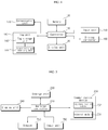
- FIG. 1 illustrates an example configuration of a home appliance system formed with a home appliance and a mobile terminal
- FIG. 2 illustrates an example configuration of a home appliance system formed with a home appliance, a mobile terminal, and a server.
- the home appliance system includes a home appliance 1 and a mobile terminal 2 that communicates with the home appliance using Near Field Communication (NFC). Further, as shown in FIG. 2 , the home appliance system may further include a server 3 that communicates with at least one of the home appliance 1 and the terminal 2.
- NFC Near Field Communication
- the home appliance 1 includes a tag unit 14 that stores data, e.g. including product information, an operation state, and/or failure information of the home appliance, and that transmits and receives data with NFC with the terminal 2.
- data e.g. including product information, an operation state, and/or failure information of the home appliance
- the tag unit 14 may be detachably formed from the home appliance 1.
- the home appliance 1 includes at least one of a display unit 12 that displays various information about an operation state and operation setting of the home appliance, an input unit 13 that inputs operation setting, and a door 11 that injects the laundry such as clothing into the washing machine.
- the display unit 12 may be formed with a liquid crystal display (LCD) and a light emitting diode (LED) and may be formed with a touch screen in some implementations.
- the input unit 13 may include at least one button or switch or a touchpad that inputs data by a touch manipulation, and when the display unit is formed with a touch screen, the touch screen functions as an input unit.
- the home appliance may be, for example, a washing machine.
- the washing machine 1 includes a drum rotatably provided within a case that forms an external appearance to receive the laundry such as clothing, and at an inner circumferential surface of the drum, a lift is provided, and when the drum rotates, the lift may move clothes upward and downward to remove a foreign substance from the laundry. Further, the washing machine 1 further includes a plurality of sensors that detect water supply, drain, and an operation state.
- the home appliance may be a washing machine having a steam spray function, a washing machine having a dry function, a dryer, or another type of home appliance having an NFC function.
- the terminal 2 includes a communication module that transmits and receives data with NFC, an input unit, and a display unit and transmits specific data to the home appliance and displays data of the home appliance.
- the terminal 2 contacts with the tag unit 14 of the home appliance through the communication module, receives data of the home appliance, and records and stores data in the tag unit.
- the terminal 2 may exchange data with the tag unit of the home appliance 1, when a contact is established.
- a contact includes a case in which the terminal and the tag unit recognize each other, and a case in which the terminal and the tag unit approach within a predetermined distance without a physical contact, e.g. by IR, Bluetooth, RF, etc, as well as a physical contact between the terminal and the tag unit, such as a wired connection or plugged connection.
- the terminal 2 has an application that transmits and receives and controls data with the home appliance 1, executes the application, displays information of the home appliance 1 received through a contact with the tag unit 14, controls the home appliance, and diagnoses whether the home appliance is in a failure state, or that performs only one or more of these functions.
- the terminal 2 executes an application
- the terminal 2 connects to the server 3, matches information of the home appliance 1 to a network identifier for connection to the server, and registers the home appliance 1 to the server 3, thereby monitoring and controlling the home appliance 1 through the network.
- the server 3 includes a database that stores information of the home appliance matched to the network identifier, and when the home appliance is connected to the network, the server 3 collects and stores information from the home appliance. In this case, the server 3 registers and stores home appliance information through the terminal 2. When the home appliance is not connected to the network, the server 3 collects and stores information of the home appliance through connection to the terminal 2.
- the server 3 may store data of failure diagnosis and provide addition data according to failure diagnosis according to a request of the terminal 2.
- FIG. 3 illustrates an example of communication through contact between a terminal and a home appliance.
- a user may determine information of the home appliance 1 through the terminal.
- the terminal 2 When the terminal 2 approaches within a predetermined distance from the tag unit 14 of the home appliance 1 and maintains for a predetermined time or more, the terminal 2 receives data stored at the tag unit of the home appliance, transmits setting data of the home appliance to the tag unit, and stores the setting data at the tag unit.
- guidance may be displayed to maintain a contact state for a predetermined time on a screen 451 of the display unit of the terminal 2.
- Guidance may be displayed with a message or an image and may be simultaneously output with a sound.
- the terminal 2 may display guidance according to communication completion on the screen and output a predetermined effect sound corresponding thereto through the speaker.
- FIG. 4 illustrates an example configuration of a home appliance.
- the home appliance (hereinafter, the washing machine 1) includes a tag unit 140, a communication unit 170, a memory 120, a display unit 130, an input unit 150, a driving controller 160, and a controller 110 that controls entire operations, as described above.
- the washing machine 1 includes a plurality of sensors and further includes elements such as a detection unit that detects a state of the washing machine and a power supply unit and a description of other elements will be omitted.
- the detection unit includes a sensor that detects a temperature, a pressure, a voltage, a current, a water level, and the rotation number and applies detected or measured data to the controller 110. For example, when supplying water to a wash processing device or when draining water from a wash processing device, the detection unit measures a water level and a temperature of supplied water, and a rotation speed of a washing tank or a drum.
- the driving controller 160 controls operation of the washing machine 1 so that the washing machine 1 performs a preset operation to correspond to a control signal applied from the controller 110. Accordingly, the washing machine 1 performs a series of strokes such as a washing stroke, a rinse stroke, and a dehydration stroke, thereby removing pollutants of the laundry.
- the driving controller 160 controls a motor that rotates a drum according to a control instruction of the controller 110, controls opening and closing of various valves provided in the washing machine, and controls operation of a drain pump.
- the driving controller 160 is separately divided according to a configuration like a motor controller and a pump controller to control the washing machine.
- At the memory 120 at least one of control data for controlling operation of the washing machine, operation data according to a washing machine course or a program, setting data input through the input unit 150, interface data in which information displayed on a screen of the display unit 130 is stored, measurement data detected while operating the washing machine, and failure data of operation when an error occurs are stored.
- the memory 120 data input from the terminal 2 through the tag unit 140 and connection data for server connection are stored, and when the washing machine is connected to the server 3, data transmitted and received from the server 3 are stored.
- the memory 120 may include a non-volatile memory such as at least one magnetic disk storage device, flash memory device, or other non-volatile solid phase memory devices.
- a non-volatile memory such as at least one magnetic disk storage device, flash memory device, or other non-volatile solid phase memory devices.
- the memory 120 may include an Electronically Erasable and Programmable Read-Only Memory (EE-PROM).
- EE-PROM Electronically Erasable and Programmable Read-Only Memory
- the EE-PROM may write and erase information by the controller 110. As power is turned off, even if power supply is stopped, the EE-PROM may be a storage device that does not erase but maintains information stored therein.
- the input unit 150 has at least one input means that inputs a predetermined signal or data to the washing machine by a user manipulation and receives an input of data such as an operation course and operation setting according to operation of the washing machine to apply the data to the controller 110.
- the input unit 150 may be formed with at least one of a button, a dome switch, a touch pad (capacitive/resistive), a jog wheel, a jog switch, a finger mouse, a rotary switch, and a jog dial or may be applied to any device that generates predetermined input data by a manipulation such as press, a rotation, a pressure, and a contact.
- the display unit 130 displays information input by the input unit 150, operation information and/or state information of the washing machine to correspond to a control instruction of the controller 110.
- the display unit 130 may display a connection state when performing a tag contact with the terminal 2 to correspond to a control instruction of the controller 110 and display a connection state, when the washing machine is connected to the network according to preset connection information.
- Such a display unit 130 is a light emitting body of a form such as a light emitting diode (LED), a liquid crystal display (LCD), and organic electroluminescence (EL) and visualizes and displays state information or failure information of the washing machine 1.
- the display unit 130 displays information of the washing machine in at least one form of a character, an image, a numeral, and a special character.
- the washing machine 1 includes an output means such as a lighting or flickering lamp, a vibration element, and a speaker in addition to the display unit 130.
- an output means such as a lighting or flickering lamp, a vibration element, and a speaker in addition to the display unit 130.
- the communication unit 170 includes at least one wire or wireless communication module and transmits and receives data by connecting to the network according to connection setting.
- the communication unit 170 transmits and receives data to and from the server 3 when connecting to the network and transmits data of the washing machine according to a request of the terminal 2.
- the communication unit 170 connects based on intrinsic information of the washing machine when connecting to the server and transmits and receives data through user authentication using ID when connecting to the terminal 2.
- the controller 110 may control an input and output of data by the input unit 150 and the display unit 130, manage data of the memory 120, and control data transmission and reception by the communication unit 170 and the tag unit 140.
- the controller 110 may store data of the washing machine at the tag unit 140, call data recorded at the tag unit 140, and/or change and control setting of the washing machine.
- the controller 110 determines a state of the tag unit 140 and reads or records data.
- the controller 110 determines whether the washing machine is connecting to the terminal 2 according to flag setting of the tag unit 140 and determines whether new data exists.
- the controller 110 reads header data of the tag unit, determines whether the washing machine is connecting to the terminal 2, and determines a data state according to flag setting.
- the controller 110 When the tag unit is in a standby state, the controller 110 reads data stored at the tag unit, resets a state of the tag unit, and when washing machine data is generated, the controller 110 stores the washing machine data at the tag unit. For example, when an error occurs in the washing machine, the controller 110 records diagnosis data according to the error at the tag unit.
- the tag unit 140 may include a tag storage unit 142 that stores data and/or a transmitting and receiving unit 144 that performs data transmission between the terminal 2 and the controller 110.
- the tag unit 140 may operate with a simple contact (tag operation) with the terminal 2 according to a NFC method and process and transmit and receive data with a desired method.
- NFC can be used in various devices, and when entire terminals including an NFC module correspond to a data specification, data can be synchronized.
- NFC can be generally performed within a communication distance of less than ten centimeters. Because NFC has a small communication distance, personal information may be less likely to be leaked.
- the tag unit 140 may read or write data through a tagged device.
- the tag unit 140 When contacting with the terminal 2, the tag unit 140 represents that the washing machine is contacting with the terminal by setting a flag, and even when new data exists, the tag unit 140 sets a flag thereof and displays a data state.
- data received and recorded from the terminal 2 and washing machine data recorded by the controller 110 are each divided and stored.
- setting data for changing washing machine setting by the terminal 2, and operation control data for controlling operation may be stored, and diagnose data for diagnosing an operation state of the washing machine or diagnose result data with a combination of data detected when operating the washing machine may be stored, and data about a present operation state of the washing machine may be stored.
- intrinsic information and model information of the washing machine 1 is stored at the tag storage unit 142.
- the model information may include a production company and a model name of the washing machine and information on whether the washing machine can communicate.
- the terminal 2 receives model information and intrinsic information of the washing machine stored at the tag storage unit 142, distinguishes the washing machine, and registers the corresponding washing machine at the server 3.
- the transmitting and receiving unit 144 transmits data stored at the tag storage unit 142 or stores received data at the tag storage unit 142 when contacting with the terminal 2. In this case, the transmitting and receiving unit 144 communicates with the terminal 2 according to an NFC method.
- the tag unit 140 may separately operate from the washing machine and may be detachably formed from the washing machine 1 in some cases.
- the tag unit 140 may transmit previously stored data to the terminal 2 and receive data from the terminal 2, and display existence of new data with a flag.
- the controller 110 determines a state of the tag unit 140, receives data of the tag unit 140 recorded in a turn-off state, and changes setting thereof or performs operation.
- the controller 110 controls the washing machine or stores specific data at the tag unit 140 based on data recorded in the tag unit 140, and particularly, when data stored at the tag unit 140 is network connection information, the controller 110 stores the network connection information at the memory 120, applies the network connection information to the communication unit 170, connects to a designated Access Point (AP) through the communication unit 170, and is connected to the network.
- AP Access Point
- the controller 110 transmits washing machine information to the server 3 by connecting to the server 3.
- the controller 110 is registered at the server 3 by the terminal 2 and is thus connected to the server 3 based on the intrinsic information such as model information of the washing machine. Further, when a network connection through the communication unit 170 is succeeded, the controller 110 may transmit information of the washing machine to the terminal 2 through the communication unit 170 without a contact through the tag unit 140.
- FIG. 5 illustrates an example configuration of a mobile terminal 2.
- the mobile terminal may be a folding type, a bar type, a swing type, a slider type, or other type of mobile terminal having an NFC function.
- FIG. 5 illustrates an example bar type mobile terminal having a front surface touch screen is described as a terminal 2.
- the terminal 2 includes a communication unit 230, a storage unit 220, a display unit 240, an input unit 260, a speaker 250, and a terminal controller 210 that controls entire operations of the terminal.
- the storage unit 220 stores control data for controlling operation of the terminal, operation data of an operation state of the terminal, a plurality of application data for performing a specific function, and data input by a user.
- the display unit 240 displays an operation state of a terminal or data of the washing machine received through the communication unit on the screen according to a control instruction of the terminal controller 210.
- the display unit 240 is a means that visually displays information and for example, the display unit 240 may include at least one of a liquid crystal display (LCD), a thin film transistor-liquid crystal display (TFT-LCD), an organic light-emitting diode (OLED), a flexible display, and a three-dimensional display (3D display).
- the display unit 240 may exist in at least two according to an implementation form of the terminal.
- the terminal may simultaneously have an external display unit and an internal display unit.
- the display unit 240 functions as an input unit 260 to input information by a user's touch by operating as a touch screen.
- the input unit 260 may include at least one button or switch, include a separate touchpad, and input an instruction such as communication, mouse point movement, screen scrolling, start, and end.
- the speaker 250 may be provided in a form of a receiver or a speaker. Further, a camera may be provided in a form appropriate to photograph an image or a moving picture of a user. A microphone may be provided in a form appropriate to input a user's voice and other voices.
- the communication unit 230 includes a tag communication module 232 that transmits and receives data by contacting with the tag unit 140 of the washing machine 1 and an Internet module 234 that transmits and receives data to and from the server 3 through a predetermined network connection. Further, the communication unit 230 may include a mobile communication module that transmits and receives data by connecting to the mobile communication network.
- the terminal controller 210 executes an application corresponding to data input through the input unit 260 and controls the terminal to perform a specific operation.
- the terminal controller 210 stores data input through the input unit 260 or the communication unit 230 at the storage unit 220 and controls to output the data through the display unit 240 or the speaker 250.
- the terminal controller 210 controls to display data of the washing machine received through the tag communication module 232 of the communication unit 230 on the screen through the display unit 240 and stores the data at the storage unit 220.
- the terminal controller 210 matches model information and intrinsic information of the washing machine 1 to a network identifier and registers the model information and the intrinsic information at the server 3 connected through the Internet module 234 of the communication unit.
- the terminal controller 210 remotely controls and monitors the washing machine using matched ID.
- the terminal controller 210 sets network connection information of the washing machine 1 to correspond to data input through the input unit 260, and when contacting with a tag of the washing machine 1 through the tag communication module 232, the terminal controller 210 records network connection information at the tag unit 140 of the washing machine 1.
- the terminal controller 210 when setting wireless communication, searches for an Access Point (AP) that can connect, sets network connection information including information of the selected AP, a password thereof, and security setting, and transmits the network connection information to the washing machine.
- AP Access Point
- the washing machine 1 stores network connection information received through the tag unit 140 and is connected to the network by connecting to a selected AP.
- the terminal controller 210 controls the display unit 240 to display an error.
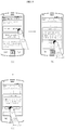
- FIGS. 6 to 10 illustrate example methods in which a terminal communicates with a home appliance.
- FIG. 6 illustrates a menu screen output to the display unit 240 when an application for controlling the washing machine of a terminal is executed.
- each of menus that execute control, information display, setting, and diagnostic of the washing machine through a contact with the tag unit 140 of the washing machine 1 is displayed with a predetermined icon.
- a guide that describes a function of the selected icon may be displayed, and in some cases, an image that implies a function may be displayed.
- a guide of a method of transmitting and receiving data through contact with the tag unit 140 of the washing machine may be displayed together with a tag on sub-menu.
- the terminal controller 210 When an application is executed, the terminal controller 210 receives an input of a network identifier and is connected to the server 3 through the communication unit 230, and when an application is initially executed, the terminal controller 210 registers a new network identifier.
- the terminal controller 210 controls to display a product registration menu of the washing machine on the screen to register the washing machine, as shown in FIG. 6(b) .
- the terminal controller 210 matches washing machine information to a network identifier to register the washing machine at the server 3.
- the terminal controller 210 receives information of the washing machine through the tag communication module 232, registers the washing machine 1, and sets the washing machine to be connected to the network.
- the terminal controller 210 sets network connection information and transmits the network connection information to the tag unit 140 of the washing machine 1 through the tag communication module 232, thereby enabling the washing machine to connect to the network, and matches washing machine information received from the tag unit 140 to a network identifier to register the washing machine to the server 3. Therefore, when the washing machine is registered, upon executing a next application, information of the washing machine corresponding to the network identifier may be automatically displayed according to data received from the server 3.
- the washing machine model may be a model that can be connected to the network.
- FIG. 7 illustrates an example NFC simple registration method of FIG. 6 .
- the terminal controller 210 searches for an AP that can be connected by wireless and outputs an AP list that can connect on a screen, as shown in FIG. 7(a) .
- a password input screen of the selected AP is displayed, as shown in FIG. 7(b) .
- security setting information of the selected AP and information about signal strength may be displayed, and a password input window may be displayed.
- a key input menu that can input a character or a numeral is displayed in a partial area on the screen.
- a guide of tag on information i.e., a position of the tag unit of the washing machine or a method of contacting with the tag unit is displayed with a message or an image.
- the tag communication module 232 of the terminal 2 and the transmitting and receiving unit of the tag unit 140 of the washing machine 1 recognize each other, and data are thus transmitted and received, i.e. exchanged.
- a guidance message representing a connection state may be displayed in the display unit 240 of the terminal 2, as shown in FIG. 7(d) , and when data are transmitted and received, an advancing state may be displayed according to product registration, as shown in FIG. 7(e) .
- the tag communication module 232 of the terminal 2 stores network connection information at the tag unit of the washing machine 1, and when information of the washing machine stored at the tag unit is received, the terminal controller 210 matches a network identifier and information of the washing machine and registers the washing machine at the server 3 through the Internet module 234. In some implementations, by applying network connection information received through the tag unit 140 to the communication unit 170 of the washing machine, the controller 110 of the washing machine sets a network connection.
- a guide message according to product registration completion is displayed on the screen, as shown in FIG. 7(f) .
- the washing machine 1 is connected to the network by connecting to a specific AP according to network connection information transmitted by the terminal 2.
- a network connection state may be displayed with an image or an icon in the display unit of the washing machine 1.
- FIG. 8 illustrates an example menu screen for changing network connection information of the washing machine.
- the washing machine can be connected only to a previously registered AP, when an AP that can connect is changed due to moving or network change, the washing machine is in a network connection impossible state.
- washing machine information reception using the network is impossible and thus network connection information of the washing machine may be reset through the tag communication module 232 of the terminal 2.
- peripheral APs that can connect are searched for and are output in a list, and when authentication information of a selected AP is input, by setting connection information, new network connection information may be set to the washing machine 1 through a contact with the tag unit 140 of the washing machine 1.
- the controller 110 of the washing machine 1 is connected to the network.
- FIGS. 9 and 10 illustrate an example error screen according to product registration.
- a product registration menu is output to the display unit of the terminal 2, as shown in FIG. 9(a) .
- NFC simple registration when NFC simple registration is selected, if the tag communication module 232 is not provided in the terminal 2, an error message is displayed on the screen, as shown in FIG. 9(b) .
- a message that guides to activate communication using the tag communication module is displayed, as shown in FIG. 9(c) .
- the screen is changed to a setting menu of NFC communication using the tag communication module.
- connection information in a product registration process When an error occurs in connection information in a product registration process, an error message according to a connection failure is displayed, as shown in FIG. 10(a) .
- connection passwords of a selected AP do not correspond, or strength of a signal is less than a predetermined value and thus when a problem exists in data transmission and reception, an error may be displayed.
- a check button When a check button is selected, an AP list is displayed on the screen and thus another AP is selected.
- network connection information may be added, as shown in FIG. 10(b) .
- new network information in order to connect a new network, by inputting an AP name, a security method, and a password, new network information may be added.
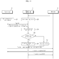
- FIG. 11 illustrates an example data flow between a washing machine, a terminal, and a server.
- the terminal 2 when executing an application for controlling the washing machine, registers information of a product, which is a target to control.
- the terminal controller 210 sets connection information so that the washing machine can be connected to a network while registering the washing machine through an NFC simple registration function (S1).
- the washing machine 1 determines a state of the provided tag unit 140 and may store intrinsic information, for example, model information of the washing machine at the tag unit 140 (S3). Further, the washing machine 1 may store information about an operation state of the washing machine and diagnosis information, when an error occurs, at the tag unit.
- connection information setting is complete, guidance may be displayed in the display unit of the terminal 2 to contact with the tag unit 140 of the washing machine 1, and thus when the terminal 2 contacts with the tag unit 140 (S2), the tag communication module 232 of the terminal 2 determines a state of the tag unit 140, may receive information, for example, model information of the washing machine previously stored at the tag unit 140, and may store preset connection information at the tag unit 140. In some implementations, the terminal 2 receives washing machine information with a contact of one time and transmits connection information to the tag unit.
- the controller 110 of the washing machine 1 checks connection termination, receives connection information stored at the tag unit 140, and applies the connection information to the communication unit 170 of the washing machine (S4).
- power of the washing machine 1 is turned off and re-operated by a user input.
- the washing machine 1 may be immediately connected to the network without re-operation.
- the communication unit 170 of the washing machine connects to a specific AP according to preset connection information to be connected to the network.
- the controller 110 determines whether the washing machine is normally connected to the network through the communication unit 170 (S5), and if the washing machine is normally connected to the network, the controller 110 controls the display unit 130 to display a connection state (S6), and when an error occurs in a connection state, the display unit 130 displays an error (S7).
- the terminal 2 further matches washing machine information received from the washing machine to a network identifier and transmits the matched washing machine information to the server 3 (S8).
- server registration by the terminal may be performed before connecting the washing machine to the network.
- the server 3 may then register the washing machine at a database according to received information and transmits a response thereof to the terminal 2 (S9).
- the washing machine 1 when the washing machine 1 is normally connected to the network, the washing machine 1 may be connected to the server 3 and transmit data of the washing machine to the server 3 (S10).
- the terminal 2 When an application is executed, the terminal 2 displays information of the washing machine corresponding to the network identifier.
- the terminal 2 may receive data from the washing machine through the network or may receive and display information of the washing machine stored at the server.
- the terminal 2 remotely monitors and controls the washing machine 1.
- FIG. 12 illustrates an example method of operating a terminal.
- the terminal 2 matches the washing machine to ID and sets the washing machine to connect to the network.
- the terminal controller 210 sets network connection information (S320). This may include searching for and controlling to display an AP list that can connect, and receiving an input of information about a selected AP. When the washing machine is not normally connected to the AP, the terminal controller 210 may control to display an error, and a menu is displayed to reset the AP.
- S320 network connection information
- the terminal controller 210 determines whether the washing machine is normally connected to the selected AP according to network connection information (S330). If the washing machine is normally connected to the selected AP, the terminal controller 210 may control to display tag guidance on a screen of the display unit 240 (S340). In some implementations, guidance of a tag method such as a guide message, i.e., a method of contacting with the tag unit including a tag unit position of the washing machine is displayed with a message or an image.
- a tag method such as a guide message, i.e., a method of contacting with the tag unit including a tag unit position of the washing machine is displayed with a message or an image.
- the tag communication module of the terminal 2 and the transmitting and receiving unit of the tag unit 140 recognize each other and transmit and receive data (S350).
- the terminal controller 210 may check whether the terminal or the washing machine supports an NFC function and determine whether the washing machine can be connected to the network (S360). When at least one of the terminal or the washing machine does not support an NFC function, the terminal controller 210 may output an error (S420) and stops registration.
- the tag communication module 232 stores the preset connection information at the tag unit 140 (S370). This step may include that the tag communication module 232 receives and analyzes information of the washing machine stored at the tag unit 140 and transmits preset connection information to the tag unit 140.
- the terminal controller 210 may check an error of data received through the tag communication module 232 (S380), and if data is normal, the terminal controller 210 sets a flag of the tag unit 140 (S390) and terminates a connection (S400).
- the terminal 2 receives information of the washing machine within a short time with a contact of one time and simultaneously stores network connection information at the tag unit of the washing machine.
- the terminal 2 may output guidance of communication completion to the display unit 240, matches received information of the washing machine and the network identifier, and may register the washing machine at the server 3 (S410).
- the server 3 may determine whether the washing machine is previously registered with another network identifier, register the washing machine in a database, and transmit a response according to registration completion to the terminal 2.
- the terminal 2 receives data of the washing machine through the network, receives data stored at the server, and remotely monitors or controls the washing machine.
- FIG. 13 illustrates an example method of controlling a washing machine.
- the controller 110 of the washing machine 1 When the controller 110 of the washing machine 1 is initially driven, the controller 110 of the washing machine 1 stores the washing machine information at the tag unit 140. The controller 110 determines a state of the provided tag unit 140 (S450) and determines whether the tag unit 140 is available (S460).
- the terminal 2 when the terminal 2 contacts with the tag unit 140, the terminal 2 awaits according to flag setting, and when communication with the terminal is complete, flag setting is changed and the tag unit 140 is in an available state.
- the controller 110 determines whether new data exists at the tag unit 140 (S470), and when new data exists, the controller 110 receives the new data from the storage unit of the tag unit 140 (S480). Further, the controller 110 may store operation information of the washing machine or failure information, when an error occurs in the washing machine, at the tag unit. In some implementations, by resetting a data flag, the controller 110 control to display that data is checked or that new data was recorded (S490).
- the controller 110 determines whether new data recorded by the terminal is network connection information (S500). If new data is network connection information, the controller 110 applies network connection information to the communication unit 170 and sets a network connection of the communication unit 170 (S510). The controller 110 controls the terminal to be in a state that can contact by changing a flag of the tag unit (S520).
- the communication unit 170 is connected to the network by connecting to a specific AP according to network connection information (S530).
- the controller 110 determines whether the washing machine is normally connected to the network (S540), if the washing machine is normally connected to the network, the controller 110 controls the display unit 140 to display a connection state (S560).
- the controller 110 transmits washing machine data by connecting to the server 3 through the communication unit 170 (S570) and changes operation of the washing machine or transmits state information of the washing machine to the terminal according to a request of the terminal by communicating with the terminal 2.
- the controller 110 controls to display an error (S550).
- the controller 110 may receive and reset new network connection information through the tag unit through the terminal 2.
- the washing machine when the washing machine is re-operated, registered network connection information is applied, but in some implementations, by immediately applying without re-operating the washing machine, the washing machine may be connected to the network.
- the controller 110 analyzes received data, changes a tag state (S580), changes washing machine setting according to data, controls operation of the washing machine, or updates course information or control data of the washing machine (S590).
- washing machine can be simultaneously connected to the network.
- the washing machine can be connected to the network without an input key or a connection program for connection to the network and change network connection information, as needed. Accordingly, the washing machine can be remotely controlled and monitored through the terminal or the server by connecting to the network.
Landscapes
- Engineering & Computer Science (AREA)
- Computer Networks & Wireless Communication (AREA)
- Physics & Mathematics (AREA)
- General Physics & Mathematics (AREA)
- Signal Processing (AREA)
- Theoretical Computer Science (AREA)
- Control Of Washing Machine And Dryer (AREA)
- Selective Calling Equipment (AREA)
- Telephonic Communication Services (AREA)
- Telephone Function (AREA)
- Business, Economics & Management (AREA)
- Emergency Management (AREA)
- Management, Administration, Business Operations System, And Electronic Commerce (AREA)
- Computer And Data Communications (AREA)
Description
- This application claims the priority benefit of Korean Patent Application No.
10-2013-0038785, filed on April 9, 2013 - This disclosure relates to a home appliance, a home appliance system, and a method of controlling the home appliance and the home appliance system, and more particularly, to a home appliance, a home appliance system, and a method of controlling the home appliance and the home appliance system that change and control communication settings of the home appliance through data transmission and reception with a terminal.
- Document
US 2010/156639 A1 discloses a home appliance according to the preamble ofclaim 1, wherein configuration data between a terminal and an electronic device are transferred. The electronic device stores the configuration data locally at a wireless receiver and a core processor interrogates the wireless receiver when the electronic device is powered up. - Document
US 2005/0037707 A1 discloses a wireless communication device including a passive radio frequency tag having a memory for receiving and storing initial configuration information utilized by the device. The initial configuration information is written to the wireless communication device without requiring that the device is fully assembled, operational, powered up, removed from packaging, etc.. An RF controller transmits initial configuration information to the passive tag using an RF signal. -
US 2008/0204199 A1 discloses a method and system for remotely configuring and/or provisioning a device that is non-operational. This device may be an electronic device including at least one setting that can be programmatically or otherwise established or adjusted to configure and/or provision of the device for its operation. - In general, laundry processing devices include a washing machine, a dryer, and a washing machine having a dryer function.
- In order to remove pollutants from the laundry such as clothes and bedding using water and detergent and a mechanical operation, a washing machine is a device that performs a process such as washing, rinsing, and dehydration. Such washing machines are classified into a top load type washing machine of rotating a drum in which the laundry is filled about a vertical axis and a front load type washing machine of rotating a drum in which the laundry is filled about a horizontal axis.
- The dryer is a device that dries the laundry to be dried by applying warm air to the laundry to be dried and that injects the laundry to be dried into a rotating drum and that dries the laundry by applying warm wind or cold wind into the drum.
- The washing machine having a dryer function has both a washing function and a dry function and is a device in which the laundry such as clothes is injected into a rotating drum, a desired function is selected and that performs washing or drying.
- Nowadays, as Internet is generally used within a home, a home appliance using a network is important. However, for Internet connection, connection setting thereof is necessary, but a keyboard or an input device similar thereto may not be provided in an entire home appliance and thus a way of connecting the home appliance to the network is requested.
- The objects are solved by the features of the independent claims. An innovative aspect of the subject matter described in this specification may be embodied in a home appliance comprising a communication unit for transmitting and receiving data; a tag unit for performing Near Field Communication (NFC) with a terminal; and a controller configured to (i) store product information at the tag unit, (ii) receive data stored at the tag unit, (iii) change an operation setting, and (iv) control a operation state, wherein the controller is configured to determine network connection information that is stored at the tag unit, to set the network connection information in the communication unit, and to transmit and receive data through a predetermined network through the communication unit. According to another aspect, a home appliance may include a display unit that outputs an operation setting and an operation state; a tag unit that performs Near Field Communication (NFC) with a terminal; and a controller that (i) stores product information at the tag unit, (ii) receives data stored at the tag unit, (iii) changes the operation setting, (iv) controls the operation state, and (v) outputs the changed operation setting to the display unit, where the controller determines network connection information that is stored at the tag unit, e.g. by the terminal, sets the network connection information, e.g. in a communication unit of the home appliance, and transmits and receives data through a predetermined network. Preferably, data are received wirelessly through a communication unit of the home appliance. According to another embodiment, a home appliance is provided having a tag unit for NFC, which is configured to store product information at the tag unit, and to be connected to a predetermined network according to network connection information stored at the tag unit. According to a further aspect, a home appliance system may include a terminal having Near Field Communication function, and a home appliance according to any of the herein described embodiments, wherein the terminal receives the product information stored at the tag unit when contacting the tag unit, stores the network connection information at the tag unit and stores the product information associated with the home appliance. Preferably, a server that stores and manages data associated with a plurality of home appliances is also provided in the system.
- These and other embodiments can each optionally include one or more of the following features. The tag unit may include a tag storage unit that stores at least one of the product information and the network connection information. The tag unit may include a transmitting and receiving unit that recognizes that the terminal contacts the tag unit and/or is within a predetermined distance to the tag unit. The controller may instruct the display unit to display a connection state, in response to the home appliance being connected to the network according to the network connection information. The controller may instruct the display unit to display an error message, in response to the home appliance not being connected to the network.
- The controller may transmit data associated with the home appliance according to a request received from the terminal and/or an external server. The controller may control operation of the home appliance according to a received control instruction in response to the home appliance being connected to the network through the communication unit. The controller may be configured to at least one of determining a state of the tag unit, receiving new data, and updating network connection information, a control program, and/or a control operation to correspond to new data, preferably in response to power of the home appliance being turned on. The controller may be configured to control an operation to correspond to new data, preferably in response to power of the home appliance being turned on. The tag unit may store data received from the terminal at the tag storage unit in response to the home appliance contacting the terminal, preferably independent of the home appliance being turned on. The tag unit may be detachably provided on the home appliance.
- Another innovative aspect of the subject matter described in this specification may be embodied in a terminal having a Near Field Communication (NFC) function, wherein the terminal (i) is configured to receive product information associated with a home appliance and stored at a tag unit when contacting the tag unit, (ii) to store network connection information at the tag unit, and (iii) to store the product information associated with the home appliance, e.g. at a server for storing and managing data associated with a plurality of home appliances. Here, the home appliance may be any of the above described embodiments. The terminal may be configured according to any embodiments described below. Further, a home appliance system is provided including the terminal and the home appliance.
- Another innovative aspect of the subject matter described in this specification may be embodied in a home appliance system that includes a terminal having a Near Field Communication (NFC) function; a server that stores and manages data associated with a plurality of home appliances; and a home appliance that (i) has a tag unit for NFC, (ii) stores product information at the tag unit, and (iii) is connected to a predetermined network according to network connection information stored at the tag unit by the terminal, where the terminal (i) receives the product information stored at the tag unit when contacting the tag unit, (ii) stores the network connection information at the tag unit, and (iii) stores the product information associated with the home appliance at the server. Here, the home appliance may be any of the above described embodiments. Further, the server may be omitted.
- These and other embodiments can each optionally include one or more of the following features. The terminal may receive the product information by contacting the tag unit and/or store the network connection information at the tag unit. The terminal may store an application for controlling the home appliance. The terminal may perform product registration through an NFC module based on a registered product existing in response to the application being executed. The terminal (i) may search for a network to which the terminal can connect. It may connect to the network and store the network connection information. The terminal may output guidance associated with the tag unit, in response to registering a product. It may (ii) store network connection information at the tag unit in response to the tag unit being recognized. The terminal may register the home appliance at the server by matching product information of the home appliance to a network identifier associated with the server. The terminal may receive and/or display information associated with the home appliance matched to the network identifier in response to the home appliance being registered.
- Another innovative aspect of the subject matter described in this specification may be embodied in a method of controlling a home appliance system that includes the actions of starting product registration of a home appliance at a terminal; collecting network connection information associated with an available network and storing the network connection information associated with the available network; receiving product information associated with the home appliance stored at a tag unit of the home appliance; storing the network connection information associated with the available network at the tag unit in response to the terminal interacting with the tag unit of the home appliance using Near Field Communication (NFC); and releasing tag contact information, matching product information to a network identifier, and registering the product information at a server. The method may be performed in any of the above described systems.
- These and other embodiments can each optionally include one or more of the following features. The actions may further include at least one of collecting network information associated with other available networks, connecting to an available network of the other available networks, and storing network connection information associated with the available network of the other available networks; and displaying a tag method using NFC in response to storing the network connection information associated with the available network of the other available networks. The actions may further include completing product registration according to a response from the server; and/or receiving and/or displaying data associated with the network identifier.
- Another innovative aspect of the subject matter described in this specification may be embodied in a method of controlling a home appliance that includes the actions of determining a state of a tag unit for Near Field Communication (NFC); in response to determining the state of the tag unit for Near Field Communication (NFC), receiving network connection information stored at a tag unit; connecting to a network according to the network connection information; transmitting data and determining registration status of the home appliance by connecting to a server in response to the home appliance being connected to the network; transmitting data associated with an operation and a state of the home appliance to a terminal associated with a registered network identifier; and controlling operation of the home appliance based on data received from the terminal.
- These and other embodiments can each optionally include one or more of the following features. The network connection information may be stored at the tag unit by the terminal using NFC. The actions may further include displaying a connection state in response to the home appliance being connected to the network; and/or displaying an error state in response to an error occurring in a connection state. The actions may further include storing product information at the tag unit.
-
-
FIG. 1 is a diagram illustrating an example configuration of a home appliance system formed with a home appliance and a terminal; -
FIG. 2 is a diagram illustrating an example configuration of a home appliance system formed with a home appliance, a terminal, and a server; -
FIG. 3 is a diagram illustrating an example of communication through contact between a terminal and a home appliance; -
FIG. 4 is a block diagram illustrating an example configuration of a home appliance; -
FIG. 5 is a block diagram illustrating an example configuration of a terminal; -
FIGS. 6 to 10 are terminal screens illustrating an example method in which a terminal communicates with a home appliance; -
FIG. 11 is a flowchart illustrating an example data flow between a home appliance, a terminal, and a server; -
FIG. 12 is a flowchart illustrating an example method of operating a terminal; and -
FIG. 13 is a flowchart illustrating an example method of controlling a home appliance. -
FIG. 1 illustrates an example configuration of a home appliance system formed with a home appliance and a mobile terminal, andFIG. 2 illustrates an example configuration of a home appliance system formed with a home appliance, a mobile terminal, and a server. - Referring to
FIG. 1 , the home appliance system includes ahome appliance 1 and amobile terminal 2 that communicates with the home appliance using Near Field Communication (NFC). Further, as shown inFIG. 2 , the home appliance system may further include aserver 3 that communicates with at least one of thehome appliance 1 and theterminal 2. - The
home appliance 1 includes atag unit 14 that stores data, e.g. including product information, an operation state, and/or failure information of the home appliance, and that transmits and receives data with NFC with theterminal 2. In some implementations, when the terminal 2 contacts with thetag unit 14 or approaches within a predetermined distance from thetag unit 14, theterminal 2 and thetag unit 14 exchange data. In some implementations, thetag unit 14 may be detachably formed from thehome appliance 1. - Further, the
home appliance 1 includes at least one of adisplay unit 12 that displays various information about an operation state and operation setting of the home appliance, aninput unit 13 that inputs operation setting, and adoor 11 that injects the laundry such as clothing into the washing machine. - The
display unit 12 may be formed with a liquid crystal display (LCD) and a light emitting diode (LED) and may be formed with a touch screen in some implementations. Further, theinput unit 13 may include at least one button or switch or a touchpad that inputs data by a touch manipulation, and when the display unit is formed with a touch screen, the touch screen functions as an input unit. - The home appliance may be, for example, a washing machine. The
washing machine 1 includes a drum rotatably provided within a case that forms an external appearance to receive the laundry such as clothing, and at an inner circumferential surface of the drum, a lift is provided, and when the drum rotates, the lift may move clothes upward and downward to remove a foreign substance from the laundry. Further, thewashing machine 1 further includes a plurality of sensors that detect water supply, drain, and an operation state. In some implementations, the home appliance may be a washing machine having a steam spray function, a washing machine having a dry function, a dryer, or another type of home appliance having an NFC function. - The
terminal 2 includes a communication module that transmits and receives data with NFC, an input unit, and a display unit and transmits specific data to the home appliance and displays data of the home appliance. - The terminal 2 contacts with the
tag unit 14 of the home appliance through the communication module, receives data of the home appliance, and records and stores data in the tag unit. In this case, theterminal 2 may exchange data with the tag unit of thehome appliance 1, when a contact is established. Here, a contact includes a case in which the terminal and the tag unit recognize each other, and a case in which the terminal and the tag unit approach within a predetermined distance without a physical contact, e.g. by IR, Bluetooth, RF, etc, as well as a physical contact between the terminal and the tag unit, such as a wired connection or plugged connection. - The
terminal 2 has an application that transmits and receives and controls data with thehome appliance 1, executes the application, displays information of thehome appliance 1 received through a contact with thetag unit 14, controls the home appliance, and diagnoses whether the home appliance is in a failure state, or that performs only one or more of these functions. - In this case, when the
terminal 2 executes an application, theterminal 2 connects to theserver 3, matches information of thehome appliance 1 to a network identifier for connection to the server, and registers thehome appliance 1 to theserver 3, thereby monitoring and controlling thehome appliance 1 through the network. - The
server 3 includes a database that stores information of the home appliance matched to the network identifier, and when the home appliance is connected to the network, theserver 3 collects and stores information from the home appliance. In this case, theserver 3 registers and stores home appliance information through theterminal 2. When the home appliance is not connected to the network, theserver 3 collects and stores information of the home appliance through connection to theterminal 2. - Further, when failure diagnosis of the home appliance is executed in the
terminal 2, theserver 3 may store data of failure diagnosis and provide addition data according to failure diagnosis according to a request of theterminal 2. -
FIG. 3 illustrates an example of communication through contact between a terminal and a home appliance. - Referring to
FIG. 3 , as the terminal 2 contacts with thetag unit 14 of thehome appliance 1, a user may determine information of thehome appliance 1 through the terminal. - When the terminal 2 approaches within a predetermined distance from the
tag unit 14 of thehome appliance 1 and maintains for a predetermined time or more, theterminal 2 receives data stored at the tag unit of the home appliance, transmits setting data of the home appliance to the tag unit, and stores the setting data at the tag unit. - In this case, for data transmission and reception with the home appliance, guidance may be displayed to maintain a contact state for a predetermined time on a
screen 451 of the display unit of theterminal 2. Guidance may be displayed with a message or an image and may be simultaneously output with a sound. - When data transmission and reception is complete, the
terminal 2 may display guidance according to communication completion on the screen and output a predetermined effect sound corresponding thereto through the speaker. -
FIG. 4 illustrates an example configuration of a home appliance. - Referring to
FIG. 4 , the home appliance (hereinafter, the washing machine 1) includes atag unit 140, acommunication unit 170, amemory 120, adisplay unit 130, aninput unit 150, a drivingcontroller 160, and acontroller 110 that controls entire operations, as described above. - Further, the
washing machine 1 includes a plurality of sensors and further includes elements such as a detection unit that detects a state of the washing machine and a power supply unit and a description of other elements will be omitted. In this case, the detection unit includes a sensor that detects a temperature, a pressure, a voltage, a current, a water level, and the rotation number and applies detected or measured data to thecontroller 110. For example, when supplying water to a wash processing device or when draining water from a wash processing device, the detection unit measures a water level and a temperature of supplied water, and a rotation speed of a washing tank or a drum. - The driving
controller 160 controls operation of thewashing machine 1 so that thewashing machine 1 performs a preset operation to correspond to a control signal applied from thecontroller 110. Accordingly, thewashing machine 1 performs a series of strokes such as a washing stroke, a rinse stroke, and a dehydration stroke, thereby removing pollutants of the laundry. - The driving
controller 160 controls a motor that rotates a drum according to a control instruction of thecontroller 110, controls opening and closing of various valves provided in the washing machine, and controls operation of a drain pump. In this case, the drivingcontroller 160 is separately divided according to a configuration like a motor controller and a pump controller to control the washing machine. - At the
memory 120, at least one of control data for controlling operation of the washing machine, operation data according to a washing machine course or a program, setting data input through theinput unit 150, interface data in which information displayed on a screen of thedisplay unit 130 is stored, measurement data detected while operating the washing machine, and failure data of operation when an error occurs are stored. - Further, at the
memory 120, data input from theterminal 2 through thetag unit 140 and connection data for server connection are stored, and when the washing machine is connected to theserver 3, data transmitted and received from theserver 3 are stored. - In some implementations, the
memory 120 may include a non-volatile memory such as at least one magnetic disk storage device, flash memory device, or other non-volatile solid phase memory devices. - For example, the
memory 120 may include an Electronically Erasable and Programmable Read-Only Memory (EE-PROM). The EE-PROM may write and erase information by thecontroller 110. As power is turned off, even if power supply is stopped, the EE-PROM may be a storage device that does not erase but maintains information stored therein. - The
input unit 150 has at least one input means that inputs a predetermined signal or data to the washing machine by a user manipulation and receives an input of data such as an operation course and operation setting according to operation of the washing machine to apply the data to thecontroller 110. - The
input unit 150 may be formed with at least one of a button, a dome switch, a touch pad (capacitive/resistive), a jog wheel, a jog switch, a finger mouse, a rotary switch, and a jog dial or may be applied to any device that generates predetermined input data by a manipulation such as press, a rotation, a pressure, and a contact. - The
display unit 130 displays information input by theinput unit 150, operation information and/or state information of the washing machine to correspond to a control instruction of thecontroller 110. Thedisplay unit 130 may display a connection state when performing a tag contact with theterminal 2 to correspond to a control instruction of thecontroller 110 and display a connection state, when the washing machine is connected to the network according to preset connection information. - Such a
display unit 130 is a light emitting body of a form such as a light emitting diode (LED), a liquid crystal display (LCD), and organic electroluminescence (EL) and visualizes and displays state information or failure information of thewashing machine 1. In this case, thedisplay unit 130 displays information of the washing machine in at least one form of a character, an image, a numeral, and a special character. - Further, the
washing machine 1 includes an output means such as a lighting or flickering lamp, a vibration element, and a speaker in addition to thedisplay unit 130. - The
communication unit 170 includes at least one wire or wireless communication module and transmits and receives data by connecting to the network according to connection setting. Thecommunication unit 170 transmits and receives data to and from theserver 3 when connecting to the network and transmits data of the washing machine according to a request of theterminal 2. In some implementations, thecommunication unit 170 connects based on intrinsic information of the washing machine when connecting to the server and transmits and receives data through user authentication using ID when connecting to theterminal 2. - The
controller 110 may control an input and output of data by theinput unit 150 and thedisplay unit 130, manage data of thememory 120, and control data transmission and reception by thecommunication unit 170 and thetag unit 140. - The
controller 110 may store data of the washing machine at thetag unit 140, call data recorded at thetag unit 140, and/or change and control setting of the washing machine. Thecontroller 110 determines a state of thetag unit 140 and reads or records data. - The
controller 110 determines whether the washing machine is connecting to theterminal 2 according to flag setting of thetag unit 140 and determines whether new data exists. Thecontroller 110 reads header data of the tag unit, determines whether the washing machine is connecting to theterminal 2, and determines a data state according to flag setting. - When the tag unit is in a standby state, the
controller 110 reads data stored at the tag unit, resets a state of the tag unit, and when washing machine data is generated, thecontroller 110 stores the washing machine data at the tag unit. For example, when an error occurs in the washing machine, thecontroller 110 records diagnosis data according to the error at the tag unit. - The
tag unit 140 may include atag storage unit 142 that stores data and/or a transmitting and receivingunit 144 that performs data transmission between the terminal 2 and thecontroller 110. - The
tag unit 140 may operate with a simple contact (tag operation) with theterminal 2 according to a NFC method and process and transmit and receive data with a desired method. NFC can be used in various devices, and when entire terminals including an NFC module correspond to a data specification, data can be synchronized. NFC can be generally performed within a communication distance of less than ten centimeters. Because NFC has a small communication distance, personal information may be less likely to be leaked. When a NFC function is activated, thetag unit 140 may read or write data through a tagged device. - When contacting with the
terminal 2, thetag unit 140 represents that the washing machine is contacting with the terminal by setting a flag, and even when new data exists, thetag unit 140 sets a flag thereof and displays a data state. - In the
tag storage unit 142, data received and recorded from theterminal 2 and washing machine data recorded by thecontroller 110 are each divided and stored. For example, in thetag storage unit 142, setting data for changing washing machine setting by theterminal 2, and operation control data for controlling operation may be stored, and diagnose data for diagnosing an operation state of the washing machine or diagnose result data with a combination of data detected when operating the washing machine may be stored, and data about a present operation state of the washing machine may be stored. - Further, intrinsic information and model information of the
washing machine 1 is stored at thetag storage unit 142. In some implementations, the model information may include a production company and a model name of the washing machine and information on whether the washing machine can communicate. In some implementations, theterminal 2 receives model information and intrinsic information of the washing machine stored at thetag storage unit 142, distinguishes the washing machine, and registers the corresponding washing machine at theserver 3. - The transmitting and receiving
unit 144 transmits data stored at thetag storage unit 142 or stores received data at thetag storage unit 142 when contacting with theterminal 2. In this case, the transmitting and receivingunit 144 communicates with theterminal 2 according to an NFC method. - Even when the
washing machine 1 is turned off and does not operate, thetag unit 140 may separately operate from the washing machine and may be detachably formed from thewashing machine 1 in some cases. - In some implementations, in a state in which the washing machine is turned off, when the terminal 2 contacts with the
tag unit 140, thetag unit 140 may transmit previously stored data to theterminal 2 and receive data from theterminal 2, and display existence of new data with a flag. - When power is turned on and operation of the washing machine is started, the
controller 110 determines a state of thetag unit 140, receives data of thetag unit 140 recorded in a turn-off state, and changes setting thereof or performs operation. - The
controller 110 controls the washing machine or stores specific data at thetag unit 140 based on data recorded in thetag unit 140, and particularly, when data stored at thetag unit 140 is network connection information, thecontroller 110 stores the network connection information at thememory 120, applies the network connection information to thecommunication unit 170, connects to a designated Access Point (AP) through thecommunication unit 170, and is connected to the network. - When a network connection through the
communication unit 170 is successful, thecontroller 110 transmits washing machine information to theserver 3 by connecting to theserver 3. In some implementations, thecontroller 110 is registered at theserver 3 by theterminal 2 and is thus connected to theserver 3 based on the intrinsic information such as model information of the washing machine. Further, when a network connection through thecommunication unit 170 is succeeded, thecontroller 110 may transmit information of the washing machine to theterminal 2 through thecommunication unit 170 without a contact through thetag unit 140. -
FIG. 5 illustrates an example configuration of amobile terminal 2. - The mobile terminal may be a folding type, a bar type, a swing type, a slider type, or other type of mobile terminal having an NFC function.
FIG. 5 illustrates an example bar type mobile terminal having a front surface touch screen is described as aterminal 2. - Referring to
FIG. 5 , theterminal 2 includes acommunication unit 230, astorage unit 220, adisplay unit 240, aninput unit 260, aspeaker 250, and aterminal controller 210 that controls entire operations of the terminal. - The
storage unit 220 stores control data for controlling operation of the terminal, operation data of an operation state of the terminal, a plurality of application data for performing a specific function, and data input by a user. - The
display unit 240 displays an operation state of a terminal or data of the washing machine received through the communication unit on the screen according to a control instruction of theterminal controller 210. - The
display unit 240 is a means that visually displays information and for example, thedisplay unit 240 may include at least one of a liquid crystal display (LCD), a thin film transistor-liquid crystal display (TFT-LCD), an organic light-emitting diode (OLED), a flexible display, and a three-dimensional display (3D display). In this case, thedisplay unit 240 may exist in at least two according to an implementation form of the terminal. For example, the terminal may simultaneously have an external display unit and an internal display unit. - Further, as touchpads are overlapped in a layer structure, the
display unit 240 functions as aninput unit 260 to input information by a user's touch by operating as a touch screen. - The
input unit 260 may include at least one button or switch, include a separate touchpad, and input an instruction such as communication, mouse point movement, screen scrolling, start, and end. - The
speaker 250 may be provided in a form of a receiver or a speaker. Further, a camera may be provided in a form appropriate to photograph an image or a moving picture of a user. A microphone may be provided in a form appropriate to input a user's voice and other voices. - The
communication unit 230 includes atag communication module 232 that transmits and receives data by contacting with thetag unit 140 of thewashing machine 1 and anInternet module 234 that transmits and receives data to and from theserver 3 through a predetermined network connection. Further, thecommunication unit 230 may include a mobile communication module that transmits and receives data by connecting to the mobile communication network. - The
terminal controller 210 executes an application corresponding to data input through theinput unit 260 and controls the terminal to perform a specific operation. Theterminal controller 210 stores data input through theinput unit 260 or thecommunication unit 230 at thestorage unit 220 and controls to output the data through thedisplay unit 240 or thespeaker 250. - The
terminal controller 210 controls to display data of the washing machine received through thetag communication module 232 of thecommunication unit 230 on the screen through thedisplay unit 240 and stores the data at thestorage unit 220. In some implementations, theterminal controller 210 matches model information and intrinsic information of thewashing machine 1 to a network identifier and registers the model information and the intrinsic information at theserver 3 connected through theInternet module 234 of the communication unit. When the washing machine is normally registered to correspond to a response of theserver 3, theterminal controller 210 remotely controls and monitors the washing machine using matched ID. - Further, the
terminal controller 210 sets network connection information of thewashing machine 1 to correspond to data input through theinput unit 260, and when contacting with a tag of thewashing machine 1 through thetag communication module 232, theterminal controller 210 records network connection information at thetag unit 140 of thewashing machine 1. - In some implementations, when setting wireless communication, the
terminal controller 210 searches for an Access Point (AP) that can connect, sets network connection information including information of the selected AP, a password thereof, and security setting, and transmits the network connection information to the washing machine. - Accordingly, the
washing machine 1 stores network connection information received through thetag unit 140 and is connected to the network by connecting to a selected AP. - In some implementations, when the
washing machine 1 is a model in which a network connection is impossible, upon registering to theserver 3, if thewashing machine 1 is a previously registered washing machine, when an error exists in washing machine information, theterminal controller 210 controls thedisplay unit 240 to display an error. -
FIGS. 6 to 10 illustrate example methods in which a terminal communicates with a home appliance. -
FIG. 6 illustrates a menu screen output to thedisplay unit 240 when an application for controlling the washing machine of a terminal is executed. - As shown in
FIG. 6(a) , when an application for controlling the washing machine is executed, each of menus that execute control, information display, setting, and diagnostic of the washing machine through a contact with thetag unit 140 of thewashing machine 1 is displayed with a predetermined icon. - When a predetermined icon is selected, a guide that describes a function of the selected icon may be displayed, and in some cases, an image that implies a function may be displayed. For example, when a tag on menu is selected, in the
display unit 240, a guide of a method of transmitting and receiving data through contact with thetag unit 140 of the washing machine may be displayed together with a tag on sub-menu. - When an application is executed, the
terminal controller 210 receives an input of a network identifier and is connected to theserver 3 through thecommunication unit 230, and when an application is initially executed, theterminal controller 210 registers a new network identifier. - When a registered washing machine does not exist at a network identifier, i.e., when registration of a new washing machine is necessary, the
terminal controller 210 controls to display a product registration menu of the washing machine on the screen to register the washing machine, as shown inFIG. 6(b) . In some implementations, theterminal controller 210 matches washing machine information to a network identifier to register the washing machine at theserver 3. - When NFC simple registration is selected by a touch or a button input in a product registration menu displayed on the screen, the
terminal controller 210 receives information of the washing machine through thetag communication module 232, registers thewashing machine 1, and sets the washing machine to be connected to the network. - The
terminal controller 210 sets network connection information and transmits the network connection information to thetag unit 140 of thewashing machine 1 through thetag communication module 232, thereby enabling the washing machine to connect to the network, and matches washing machine information received from thetag unit 140 to a network identifier to register the washing machine to theserver 3. Therefore, when the washing machine is registered, upon executing a next application, information of the washing machine corresponding to the network identifier may be automatically displayed according to data received from theserver 3. In some implementations, the washing machine model may be a model that can be connected to the network. -
FIG. 7 illustrates an example NFC simple registration method ofFIG. 6 . - When NFC simple registration is selected, the
terminal controller 210 searches for an AP that can be connected by wireless and outputs an AP list that can connect on a screen, as shown inFIG. 7(a) . - When one of the APs of the list is selected, a password input screen of the selected AP is displayed, as shown in
FIG. 7(b) . - In this case, security setting information of the selected AP and information about signal strength may be displayed, and a password input window may be displayed. When the password input window is selected, a key input menu that can input a character or a numeral is displayed in a partial area on the screen.
- As a password input is complete, when a connection key is selected, a message that guides so that the terminal 2 contacts with the
tag unit 140 of thewashing machine 1 is displayed on the screen, as shown inFIG. 7(c) . - In some implementations, a guide of tag on information, i.e., a position of the tag unit of the washing machine or a method of contacting with the tag unit is displayed with a message or an image.
- When the terminal 2 approaches within a predetermined distance from the
tag unit 140 of thewashing machine 1 or contacts with thetag unit 140, thetag communication module 232 of theterminal 2 and the transmitting and receiving unit of thetag unit 140 of thewashing machine 1 recognize each other, and data are thus transmitted and received, i.e. exchanged. - A guidance message representing a connection state may be displayed in the
display unit 240 of theterminal 2, as shown inFIG. 7(d) , and when data are transmitted and received, an advancing state may be displayed according to product registration, as shown inFIG. 7(e) . - The
tag communication module 232 of the terminal 2 stores network connection information at the tag unit of thewashing machine 1, and when information of the washing machine stored at the tag unit is received, theterminal controller 210 matches a network identifier and information of the washing machine and registers the washing machine at theserver 3 through theInternet module 234. In some implementations, by applying network connection information received through thetag unit 140 to thecommunication unit 170 of the washing machine, thecontroller 110 of the washing machine sets a network connection. - When product registration is complete, a guide message according to product registration completion is displayed on the screen, as shown in
FIG. 7(f) . After power of thewashing machine 1 is turned off according to guidance, when thewashing machine 1 is re-operated, thewashing machine 1 is connected to the network by connecting to a specific AP according to network connection information transmitted by theterminal 2. When being connecting to the network, a network connection state may be displayed with an image or an icon in the display unit of thewashing machine 1. -
FIG. 8 illustrates an example menu screen for changing network connection information of the washing machine. - Because the washing machine can be connected only to a previously registered AP, when an AP that can connect is changed due to moving or network change, the washing machine is in a network connection impossible state. When the washing machine is not connected to the network, washing machine information reception using the network is impossible and thus network connection information of the washing machine may be reset through the
tag communication module 232 of theterminal 2. - As shown in
FIG. 8(a) , when a setting menu of menu items of an application is selected, information of a registered product, i.e., information of the washing machine as well as setting of an application may be changed. - When product registration setting is selected to change, a product registration menu is displayed on the screen, as shown in
FIG. 8(b) . - In some implementations, when NFC product registration is selected, as described in
FIG. 7 , peripheral APs that can connect are searched for and are output in a list, and when authentication information of a selected AP is input, by setting connection information, new network connection information may be set to thewashing machine 1 through a contact with thetag unit 140 of thewashing machine 1. - By applying network connection information newly stored at the
tag unit 140 to thecommunication unit 170, thecontroller 110 of thewashing machine 1 is connected to the network. -
FIGS. 9 and10 illustrate an example error screen according to product registration. - As described above, when initially registering a product or when changing setting of a previously registered product, a product registration menu is output to the display unit of the
terminal 2, as shown inFIG. 9(a) . - In some implementations, when NFC simple registration is selected, if the
tag communication module 232 is not provided in theterminal 2, an error message is displayed on the screen, as shown inFIG. 9(b) . - In some implementations, when the tag communication module is provided in the
terminal 2, but does not operate, a message that guides to activate communication using the tag communication module is displayed, as shown inFIG. 9(c) . In some implementations, when 'yes' is selected, the screen is changed to a setting menu of NFC communication using the tag communication module. - When an error occurs in connection information in a product registration process, an error message according to a connection failure is displayed, as shown in
FIG. 10(a) . When connection passwords of a selected AP do not correspond, or strength of a signal is less than a predetermined value and thus when a problem exists in data transmission and reception, an error may be displayed. When a check button is selected, an AP list is displayed on the screen and thus another AP is selected. - When connecting to an AP that is not displayed in the list, network connection information may be added, as shown in
FIG. 10(b) . - In some implementations, in order to connect a new network, by inputting an AP name, a security method, and a password, new network information may be added.
-
FIG. 11 illustrates an example data flow between a washing machine, a terminal, and a server. - Referring to
FIG. 11 , when executing an application for controlling the washing machine, theterminal 2 registers information of a product, which is a target to control. In some implementations, theterminal controller 210 sets connection information so that the washing machine can be connected to a network while registering the washing machine through an NFC simple registration function (S1). - The
washing machine 1 determines a state of the providedtag unit 140 and may store intrinsic information, for example, model information of the washing machine at the tag unit 140 (S3). Further, thewashing machine 1 may store information about an operation state of the washing machine and diagnosis information, when an error occurs, at the tag unit. - When the
terminal 2 performs simple registration, if connection information setting is complete, guidance may be displayed in the display unit of theterminal 2 to contact with thetag unit 140 of thewashing machine 1, and thus when the terminal 2 contacts with the tag unit 140 (S2), thetag communication module 232 of theterminal 2 determines a state of thetag unit 140, may receive information, for example, model information of the washing machine previously stored at thetag unit 140, and may store preset connection information at thetag unit 140. In some implementations, theterminal 2 receives washing machine information with a contact of one time and transmits connection information to the tag unit. - When a connection of the
terminal 2 to thetag unit 140 is terminated, thecontroller 110 of thewashing machine 1 checks connection termination, receives connection information stored at thetag unit 140, and applies the connection information to thecommunication unit 170 of the washing machine (S4). - In some implementations, power of the
washing machine 1 is turned off and re-operated by a user input. In some implementations, thewashing machine 1 may be immediately connected to the network without re-operation. - After re-operation, the
communication unit 170 of the washing machine connects to a specific AP according to preset connection information to be connected to the network. Thecontroller 110 determines whether the washing machine is normally connected to the network through the communication unit 170 (S5), and if the washing machine is normally connected to the network, thecontroller 110 controls thedisplay unit 130 to display a connection state (S6), and when an error occurs in a connection state, thedisplay unit 130 displays an error (S7). - Preferably, the
terminal 2 further matches washing machine information received from the washing machine to a network identifier and transmits the matched washing machine information to the server 3 (S8). In some implementations, server registration by the terminal may be performed before connecting the washing machine to the network. - The
server 3 may then register the washing machine at a database according to received information and transmits a response thereof to the terminal 2 (S9). - Further, when the
washing machine 1 is normally connected to the network, thewashing machine 1 may be connected to theserver 3 and transmit data of the washing machine to the server 3 (S10). - When an application is executed, the
terminal 2 displays information of the washing machine corresponding to the network identifier. When thewashing machine 1 is connected to the network, theterminal 2 may receive data from the washing machine through the network or may receive and display information of the washing machine stored at the server. - Accordingly, the
terminal 2 remotely monitors and controls thewashing machine 1. -
FIG. 12 illustrates an example method of operating a terminal. - As shown in
FIG. 12 , when simple registration is selected in a product registration menu (S310), the terminal 2 matches the washing machine to ID and sets the washing machine to connect to the network. - The
terminal controller 210 sets network connection information (S320). This may include searching for and controlling to display an AP list that can connect, and receiving an input of information about a selected AP. When the washing machine is not normally connected to the AP, theterminal controller 210 may control to display an error, and a menu is displayed to reset the AP. - The
terminal controller 210 determines whether the washing machine is normally connected to the selected AP according to network connection information (S330). If the washing machine is normally connected to the selected AP, theterminal controller 210 may control to display tag guidance on a screen of the display unit 240 (S340). In some implementations, guidance of a tag method such as a guide message, i.e., a method of contacting with the tag unit including a tag unit position of the washing machine is displayed with a message or an image. - When the
terminal 2 adjacently positions within a predetermined distance from thetag unit 140 of thewashing machine 1 or contacts with the tag unit, the tag communication module of theterminal 2 and the transmitting and receiving unit of thetag unit 140 recognize each other and transmit and receive data (S350). - In some implementations, the
terminal controller 210 may check whether the terminal or the washing machine supports an NFC function and determine whether the washing machine can be connected to the network (S360). When at least one of the terminal or the washing machine does not support an NFC function, theterminal controller 210 may output an error (S420) and stops registration. - When the terminal and the washing machine support the NFC function, the
tag communication module 232 stores the preset connection information at the tag unit 140 (S370). This step may include that thetag communication module 232 receives and analyzes information of the washing machine stored at thetag unit 140 and transmits preset connection information to thetag unit 140. Theterminal controller 210 may check an error of data received through the tag communication module 232 (S380), and if data is normal, theterminal controller 210 sets a flag of the tag unit 140 (S390) and terminates a connection (S400). - In some implementations, the
terminal 2 receives information of the washing machine within a short time with a contact of one time and simultaneously stores network connection information at the tag unit of the washing machine. - The
terminal 2 may output guidance of communication completion to thedisplay unit 240, matches received information of the washing machine and the network identifier, and may register the washing machine at the server 3 (S410). - In some implementations, the
server 3 may determine whether the washing machine is previously registered with another network identifier, register the washing machine in a database, and transmit a response according to registration completion to theterminal 2. - Thereafter, when the washing machine is connected to the network, the
terminal 2 receives data of the washing machine through the network, receives data stored at the server, and remotely monitors or controls the washing machine. -
FIG. 13 illustrates an example method of controlling a washing machine. - When the
controller 110 of thewashing machine 1 is initially driven, thecontroller 110 of thewashing machine 1 stores the washing machine information at thetag unit 140. Thecontroller 110 determines a state of the provided tag unit 140 (S450) and determines whether thetag unit 140 is available (S460). - In some implementations, when the terminal 2 contacts with the
tag unit 140, theterminal 2 awaits according to flag setting, and when communication with the terminal is complete, flag setting is changed and thetag unit 140 is in an available state. - The
controller 110 determines whether new data exists at the tag unit 140 (S470), and when new data exists, thecontroller 110 receives the new data from the storage unit of the tag unit 140 (S480). Further, thecontroller 110 may store operation information of the washing machine or failure information, when an error occurs in the washing machine, at the tag unit. In some implementations, by resetting a data flag, thecontroller 110 control to display that data is checked or that new data was recorded (S490). - The
controller 110 determines whether new data recorded by the terminal is network connection information (S500). If new data is network connection information, thecontroller 110 applies network connection information to thecommunication unit 170 and sets a network connection of the communication unit 170 (S510). Thecontroller 110 controls the terminal to be in a state that can contact by changing a flag of the tag unit (S520). - The
communication unit 170 is connected to the network by connecting to a specific AP according to network connection information (S530). - The
controller 110 determines whether the washing machine is normally connected to the network (S540), if the washing machine is normally connected to the network, thecontroller 110 controls thedisplay unit 140 to display a connection state (S560). Thecontroller 110 transmits washing machine data by connecting to theserver 3 through the communication unit 170 (S570) and changes operation of the washing machine or transmits state information of the washing machine to the terminal according to a request of the terminal by communicating with theterminal 2. - If the washing machine is not normally connected to the network, the
controller 110 controls to display an error (S550). In some implementations, thecontroller 110 may receive and reset new network connection information through the tag unit through theterminal 2. - In some implementations, when the washing machine is re-operated, registered network connection information is applied, but in some implementations, by immediately applying without re-operating the washing machine, the washing machine may be connected to the network.
- If new data is not network connection information at S500, the
controller 110 analyzes received data, changes a tag state (S580), changes washing machine setting according to data, controls operation of the washing machine, or updates course information or control data of the washing machine (S590). - Therefore, product information of the washing machine is registered at the terminal and the server through NFC with the terminal, and the washing machine can be simultaneously connected to the network. The washing machine can be connected to the network without an input key or a connection program for connection to the network and change network connection information, as needed. Accordingly, the washing machine can be remotely controlled and monitored through the terminal or the server by connecting to the network.
Claims (13)
- A home appliance (1) comprising:a communication unit (170) for transmitting and receiving data;a tag unit (140) for performing Near Field Communication, NFC, with a terminal (2); anda controller (110) configured to (i) store product information at the tag unit, (ii) receive data stored at the tag unit, (iii) change an operation setting, and (iv) control a operation state,wherein the controller (110) is configured to determine network connection information that is stored at the tag unit (140), to set the network connection information in the communication unit (170), and to transmit and receive data through a predetermined network through the communication unit (170),characterized in that the controller (110) is configured to transmit, in case a network connection through the communication unit (170) is successful, data of the home appliance (1) to the server (3) based on a product information of the home appliance (1),wherein after the home appliance (1) is registered to the server (3) by the terminal (2), the operation of the home appliance (1) is controlled based on data received from the terminal (2).
- The home appliance of claim 1, wherein the tag unit (140) comprises at least one of:a tag storage unit for storing the product information and/or the network connection information; anda transmitting and receiving unit for recognizing the terminal (2) that contacts the tag unit (140) or is within a predetermined distance to the tag unit (140), and for transmitting and receiving data.
- The home appliance of claim 1 or 2, wherein the controller controls to transmit the data of the home appliance (1) according to a request received from the terminal (2) or an external server (3) and controls operation of the home appliance (1) according to a received control instruction in response to the home appliance (1) being connected to the network through the communication unit (170).
- The home appliance of any one of the preceding claims, wherein the controller (110) is configured for at least one of determining a state of the tag unit (140), receiving new data, and updating network connection information, a control program, and/or control operation to correspond to new data.
- The home appliance of any one of the preceding claims, wherein the tag unit (140) is detachably provided on the home appliance (1).
- A home appliance system, comprising:a terminal (2) having a Near Field Communication, NFC, function; anda home appliance (1) that (i) has a tag unit (140) for NFC, and is configured to (ii) store product information at the tag unit (140), and (iii) to be connected to a predetermined network according to network connection information stored at the tag unit (140) by the terminal (2),wherein the terminal is configured to (i) receive the product information stored at the tag unit when contacting the tag unit, (ii) store the network connection information at the tag unit (140), and (iii) store the product information associated with the home appliance (1), characterized in that the terminal (2) is configured to register the home appliance (1) at the server (3) by matching product information of the home appliance (1) to a network identifier, receive and display data of the home appliance (1) matched to the network identifier, and remotely control the home appliance (1).
- The home appliance system of claim 6, wherein:the terminal stores an application for controlling the home appliance, and/orthe terminal performs product registration through an NFC module based on a registered product existing in response to an application being executed.
- The home appliance system of claim 6 or 7, wherein the terminal is configured to (i) search for a network to which the terminal can connect, to connect to the network, to store the network connection information, and to output guidance associated with the tag unit, in response to registering a product and (ii) to store the network connection information at the tag unit in response to the tag unit being recognized.
- A method of controlling a home appliance system, the method comprising:starting product registration of a home appliance (1) at a terminal (2);collecting network connection information associated with an available network and storing the network connection information associated with the available network;receiving product information associated with the home appliance (1) stored at a tag unit (140) of the home appliance (1);storing the network connection information associated with the available network at the tag unit (140) in response to the terminal interacting with the tag unit (140) of the home appliance (1) using Near Field Communication, NFC; releasing tag contact and registering the home appliance (1) at the server (3) by matching product information of the home appliance (1) to a network identifier, when the home appliance (1) is registered to the server (3) by the terminal (2), receiving and displaying data of the home appliance (1) matched to the network identifier, andremotely controlling the home appliance (1).
- The method of claim 9, further comprising:collecting network information associated with other available networks, connecting to an available network of the other available networks, and storing network connection information associated with the available network of the other available networks; anddisplaying a tag method using NFC in response to storing the network connection information associated with the available network of the other available networks.
- A method of controlling a home appliance, the method comprising:determining a state of a tag unit (140) for Near Field Communication, NFC; in response to determining the state of the tag unit (140) for Near Field Communication, NFC, storing product information at the tag unit and receiving network connection information stored at a tag unit (140);connecting to a network according to the network connection information;transmitting data and determining registration status of the home appliance (1) by connecting to a server (3) in response to the home appliance (1) being connected to the network;transmitting data associated with an operation and a state of the home appliance (1) to a server (3); andcontrolling operation of the home appliance (1) based on data received from the terminal (2),wherein the home appliance (1) is registered to the server (3) by the terminal (2), and connects to the server (3) based on a product information of the home appliance (1)
- The method of claim 11, wherein the network connection information is stored at the tag unit by the terminal using NFC.
- The method of claim 11 or 12, further comprising:displaying a connection state in response to the home appliance being connected to the network; and/ordisplaying an error state in response to an error occurring in a connection state.
Applications Claiming Priority (1)
| Application Number | Priority Date | Filing Date | Title |
|---|---|---|---|
| KR1020130038785A KR102051369B1 (en) | 2013-04-09 | 2013-04-09 | A Home Appliance, System AND A Controlling Method for A Home Appliance |
Publications (3)
| Publication Number | Publication Date |
|---|---|
| EP2800079A2 EP2800079A2 (en) | 2014-11-05 |
| EP2800079A3 EP2800079A3 (en) | 2015-01-07 |
| EP2800079B1 true EP2800079B1 (en) | 2018-07-25 |
Family
ID=50439287
Family Applications (1)
| Application Number | Title | Priority Date | Filing Date |
|---|---|---|---|
| EP14163847.8A Not-in-force EP2800079B1 (en) | 2013-04-09 | 2014-04-08 | Home appliance, home appliance system, and method of controlling the same |
Country Status (8)
| Country | Link |
|---|---|
| US (1) | US9722668B2 (en) |
| EP (1) | EP2800079B1 (en) |
| JP (1) | JP6006255B2 (en) |
| KR (1) | KR102051369B1 (en) |
| CN (1) | CN104104565B (en) |
| AU (1) | AU2014201961B2 (en) |
| BR (1) | BR102014008066B1 (en) |
| RU (1) | RU2577219C2 (en) |
Families Citing this family (39)
| Publication number | Priority date | Publication date | Assignee | Title |
|---|---|---|---|---|
| KR101924962B1 (en) * | 2012-10-04 | 2018-12-04 | 엘지전자 주식회사 | Mobile terminal, home appliance, and nethod for operating the same |
| JP6312503B2 (en) * | 2014-04-01 | 2018-04-18 | キヤノン株式会社 | Printing system, information processing apparatus, control method, program |
| TWI559966B (en) * | 2014-11-04 | 2016-12-01 | Mooredoll Inc | Method and device of community interaction with toy as the center |
| CN104328623A (en) * | 2014-11-11 | 2015-02-04 | 南京乐金熊猫电器有限公司 | Method for transmitting washing program to washer from mobile equipment |
| CN104536299B (en) * | 2014-12-09 | 2017-11-10 | 广东欧珀移动通信有限公司 | Start the method, apparatus and system and central control equipment of household electrical appliances |
| CN104730930B (en) * | 2015-01-16 | 2017-12-29 | 小米科技有限责任公司 | Clothing method for sorting, clothes washing method and device |
| KR20160111211A (en) * | 2015-03-16 | 2016-09-26 | 삼성전자주식회사 | Method for communicating data and electronic device there |
| CZ306378B6 (en) * | 2015-03-26 | 2016-12-28 | Rieter Cz S.R.O. | Yarn producing or processing textile machine provided with wireless communication interface |
| CN106292565A (en) * | 2015-06-05 | 2017-01-04 | 博西华电器(江苏)有限公司 | The control method of home appliance and control system |
| KR101676388B1 (en) * | 2015-06-08 | 2016-11-15 | 재단법인 실감교류인체감응솔루션연구단 | Remote device control system with menu device and method thereof |
| US10003653B2 (en) * | 2015-08-13 | 2018-06-19 | Delaware Capital Formation, Inc. | Wireless interface module for chemical dispensing system |
| EP3716182A1 (en) | 2015-09-17 | 2020-09-30 | Laundry 2.0, LLC | System for commercial laundry services and facilities |
| JP6232037B2 (en) * | 2015-12-04 | 2017-11-15 | 株式会社日本トリム | Electrolyzed water generation system |
| CN108604215B (en) | 2016-02-19 | 2022-04-05 | 三星电子株式会社 | Dongle device and method for controlling the same |
| CN107151895A (en) * | 2016-03-03 | 2017-09-12 | 松下家电研究开发(杭州)有限公司 | A kind of washing machine and its application method without operation display panel |
| KR101695213B1 (en) * | 2016-04-19 | 2017-01-11 | 재단법인 실감교류인체감응솔루션연구단 | Remote device control system with menu device and method thereof |
| KR102602847B1 (en) * | 2016-06-03 | 2023-11-16 | 엘지전자 주식회사 | Clothes treating apparatus |
| PL3290565T3 (en) * | 2016-08-31 | 2021-10-11 | Electrolux Appliances Aktiebolag | Household appliance with a touch display |
| CN106533850A (en) * | 2016-10-14 | 2017-03-22 | 杭州鸿雁智能科技有限公司 | Panel scene control method based on NFC card mode |
| KR102458441B1 (en) * | 2017-06-16 | 2022-10-25 | 삼성전자주식회사 | Washing machine system having the same and controlling method of washing machine |
| CN109881430A (en) * | 2017-12-06 | 2019-06-14 | 青岛海尔洗衣机有限公司 | A remote configuration method of washing machine control program |
| KR102572483B1 (en) * | 2018-05-25 | 2023-08-30 | 삼성전자주식회사 | Electronic device and method for controlling an external electronic device |
| US10423869B1 (en) | 2018-06-28 | 2019-09-24 | Haier Us Appliance Solutions, Inc. | Interchangeable tag communications systems for consumer appliances |
| CN111341034A (en) * | 2018-12-19 | 2020-06-26 | 青岛海尔洗衣机有限公司 | Networked master control laundry treatment system |
| CN112305924B (en) * | 2019-07-31 | 2024-07-19 | 广东美的制冷设备有限公司 | Control method, device, electronic device and storage medium for household appliances |
| KR102786647B1 (en) * | 2019-09-04 | 2025-03-25 | 엘지전자 주식회사 | Method, apparatus and system of detecting foreign objects in washing/dryer machine |
| JP2021094258A (en) * | 2019-12-18 | 2021-06-24 | 東芝ライフスタイル株式会社 | Washing system, server, control method, and program |
| JP7560094B2 (en) * | 2020-06-05 | 2024-10-02 | 株式会社川本製作所 | COMMUNICATION DEVICE, COMMUNICATION PROGRAM, AND COMMUNICATION SYSTEM |
| CN112187591A (en) * | 2020-09-23 | 2021-01-05 | 合肥美的电冰箱有限公司 | Label information management method, terminal, server, refrigerator and readable storage medium |
| US12647296B2 (en) | 2021-01-18 | 2026-06-02 | Mitsubishi Electric Corporation | Appliance control system, home appliance, and notification control method for home appliance |
| CN114815634A (en) * | 2021-01-27 | 2022-07-29 | 青岛海尔洗衣机有限公司 | Intelligent control method of NFC household appliance |
| KR20220129353A (en) * | 2021-03-16 | 2022-09-23 | 삼성전자주식회사 | Apparatus and method for providing internet of things service |
| CN115616924B (en) * | 2021-07-15 | 2025-07-18 | 芜湖美的厨卫电器制造有限公司 | Method and device for confirming rights of household appliances |
| KR102566967B1 (en) * | 2021-12-14 | 2023-08-16 | 안희철 | Iot service system based on wireless tag |
| KR20230116531A (en) | 2022-01-28 | 2023-08-04 | 삼성전자주식회사 | Electronic apparatus and control method thereof |
| US20250168904A1 (en) * | 2022-02-28 | 2025-05-22 | Samsung Electronics Co., Ltd. | Method and device for device registration management and control |
| WO2024210534A1 (en) * | 2023-04-04 | 2024-10-10 | 주식회사 웰케어스 | Electronic tag-based iot device and method and apparatus for controlling same |
| KR102727189B1 (en) * | 2023-04-04 | 2024-11-25 | 주식회사 웰케어스 | Electronic Tag-Based IoT Device and Method and Apparatus for Controlling the Same |
| CN116446145B (en) * | 2023-05-09 | 2025-11-11 | 四川虹美智能科技有限公司 | Control method of intelligent washing machine |
Family Cites Families (20)
| Publication number | Priority date | Publication date | Assignee | Title |
|---|---|---|---|---|
| US6876295B1 (en) * | 1998-12-16 | 2005-04-05 | Symbol Technologies, Inc. | Wireless communication devices configurable via passive tags |
| DE10340627A1 (en) | 2003-09-03 | 2005-04-07 | Infineon Technologies Ag | Controlled domestic and/or industrial appliance system e.g. refrigerator, washing machine, includes memory unit for storing domestic- and/or industrial- control program |
| KR20060023410A (en) * | 2004-09-09 | 2006-03-14 | 엘지전자 주식회사 | Laundry system and its control method |
| JPWO2007099609A1 (en) * | 2006-02-28 | 2009-07-16 | パナソニック株式会社 | Device authentication system, mobile terminal, information device, device authentication server, and device authentication method |
| US7852198B2 (en) * | 2006-07-18 | 2010-12-14 | Hewlett-Packard Development Company, L.P. | RF tag |
| AU2007288668B2 (en) * | 2006-08-23 | 2010-09-09 | Lg Electronics Inc. | Multiple laundry treating machine |
| US8098160B2 (en) * | 2007-01-22 | 2012-01-17 | Cisco Technology, Inc. | Method and system for remotely provisioning and/or configuring a device |
| TW200849886A (en) * | 2007-06-15 | 2008-12-16 | D Link Corp | Network device with display module |
| CN101364911B (en) | 2007-08-06 | 2011-11-09 | 海尔集团公司 | Household appliance network system capable of realizing equipment recognition |
| US20100156639A1 (en) * | 2008-12-18 | 2010-06-24 | Nathaniel Christopher Herwig | Device configuration system and method |
| CN101894452B (en) | 2010-04-30 | 2013-06-26 | 中山大学 | Mobile communication network-based intelligent home control method and system |
| CN101848126A (en) | 2010-04-30 | 2010-09-29 | 中山大学 | Interactive method for controlling intelligent home equipment and home network system |
| EP2573247B1 (en) * | 2010-05-17 | 2021-01-27 | LG Electronics Inc. | Home appliance, home appliance system, and method for operating same |
| CN101998695B (en) | 2010-11-04 | 2014-03-26 | 深圳市江波龙电子有限公司 | Method, device and system for configuring WiFi setting parameters of terminal equipment |
| FR2976103B1 (en) * | 2011-06-03 | 2013-05-17 | St Microelectronics Rousset | ASSISTING THE POSITIONING OF A TRANSPONDER |
| US9850613B2 (en) * | 2011-09-09 | 2017-12-26 | Panasonic Intellectual Property Management Co., Ltd. | Laundry system, communication device, communication method, communication program and washing machine |
| EP2755374B1 (en) * | 2011-09-09 | 2018-08-22 | Panasonic Corporation | Communication method and apparatus |
| US9641596B2 (en) * | 2012-01-25 | 2017-05-02 | Panasonic Intellectual Property Management Co., Ltd. | Home appliance information management apparatus, home appliance information sharing method, and home appliance information sharing system |
| EP2624081B1 (en) * | 2012-01-31 | 2018-01-10 | Nxp B.V. | Configuration method, configuration device, computer program product and control system |
| EP2842360A4 (en) * | 2012-04-26 | 2015-12-23 | Nokia Technologies Oy | Method and apparatus for wireless network access parameter sharing |
-
2013
- 2013-04-09 KR KR1020130038785A patent/KR102051369B1/en active Active
-
2014
- 2014-04-03 BR BR102014008066-0A patent/BR102014008066B1/en not_active IP Right Cessation
- 2014-04-07 AU AU2014201961A patent/AU2014201961B2/en not_active Ceased
- 2014-04-08 RU RU2014113756/12A patent/RU2577219C2/en not_active IP Right Cessation
- 2014-04-08 EP EP14163847.8A patent/EP2800079B1/en not_active Not-in-force
- 2014-04-08 US US14/247,863 patent/US9722668B2/en not_active Expired - Fee Related
- 2014-04-09 JP JP2014080377A patent/JP6006255B2/en not_active Expired - Fee Related
- 2014-04-09 CN CN201410140808.XA patent/CN104104565B/en not_active Expired - Fee Related
Non-Patent Citations (1)
| Title |
|---|
| None * |
Also Published As
| Publication number | Publication date |
|---|---|
| EP2800079A2 (en) | 2014-11-05 |
| RU2014113756A (en) | 2015-10-20 |
| RU2577219C2 (en) | 2016-03-10 |
| KR20140122108A (en) | 2014-10-17 |
| US20140300450A1 (en) | 2014-10-09 |
| EP2800079A3 (en) | 2015-01-07 |
| BR102014008066B1 (en) | 2022-05-31 |
| CN104104565A (en) | 2014-10-15 |
| US9722668B2 (en) | 2017-08-01 |
| AU2014201961B2 (en) | 2016-01-28 |
| CN104104565B (en) | 2018-04-06 |
| BR102014008066A2 (en) | 2016-04-05 |
| JP6006255B2 (en) | 2016-10-12 |
| KR102051369B1 (en) | 2019-12-03 |
| AU2014201961A1 (en) | 2014-10-23 |
| JP2014200692A (en) | 2014-10-27 |
Similar Documents
| Publication | Publication Date | Title |
|---|---|---|
| AU2014201961B2 (en) | Home appliance, home appliance system, and method of controlling the same | |
| AU2014201963A1 (en) | Home appliance and method of controlling the same | |
| EP3042506B1 (en) | Mobile terminal and method of operating thereof with a washing machine | |
| KR102504104B1 (en) | Washing machine, Mobile, Method for controlling mobile and Method for controlling washing machine | |
| EP2789725B1 (en) | Washing machine control system and method of controlling the same | |
| EP2430765B1 (en) | Mobile terminal controlling washing machine, method of operating the mobile terminal, washing machine, and method of operating the washing machine | |
| KR20110126436A (en) | Home appliance system and its operation method | |
| KR101709480B1 (en) | Home appliance and operating method | |
| JP5945693B2 (en) | Washing machine communication system | |
| JP5945694B2 (en) | Washing machine communication system | |
| CN114816555A (en) | NFC household appliance control method | |
| WO2022242385A1 (en) | Household appliance control method and apparatus | |
| KR20150043880A (en) | A home appliance and a controlling system thereof |
Legal Events
| Date | Code | Title | Description |
|---|---|---|---|
| PUAI | Public reference made under article 153(3) epc to a published international application that has entered the european phase |
Free format text: ORIGINAL CODE: 0009012 |
|
| 17P | Request for examination filed |
Effective date: 20140408 |
|
| AK | Designated contracting states |
Kind code of ref document: A2 Designated state(s): AL AT BE BG CH CY CZ DE DK EE ES FI FR GB GR HR HU IE IS IT LI LT LU LV MC MK MT NL NO PL PT RO RS SE SI SK SM TR |
|
| AX | Request for extension of the european patent |
Extension state: BA ME |
|
| PUAL | Search report despatched |
Free format text: ORIGINAL CODE: 0009013 |
|
| AK | Designated contracting states |
Kind code of ref document: A3 Designated state(s): AL AT BE BG CH CY CZ DE DK EE ES FI FR GB GR HR HU IE IS IT LI LT LU LV MC MK MT NL NO PL PT RO RS SE SI SK SM TR |
|
| AX | Request for extension of the european patent |
Extension state: BA ME |
|
| RIC1 | Information provided on ipc code assigned before grant |
Ipc: G08C 17/02 20060101AFI20141128BHEP |
|
| R17P | Request for examination filed (corrected) |
Effective date: 20150706 |
|
| RBV | Designated contracting states (corrected) |
Designated state(s): AL AT BE BG CH CY CZ DE DK EE ES FI FR GB GR HR HU IE IS IT LI LT LU LV MC MK MT NL NO PL PT RO RS SE SI SK SM TR |
|
| GRAP | Despatch of communication of intention to grant a patent |
Free format text: ORIGINAL CODE: EPIDOSNIGR1 |
|
| STAA | Information on the status of an ep patent application or granted ep patent |
Free format text: STATUS: GRANT OF PATENT IS INTENDED |
|
| INTG | Intention to grant announced |
Effective date: 20180219 |
|
| RAP1 | Party data changed (applicant data changed or rights of an application transferred) |
Owner name: LG ELECTRONICS INC. |
|
| GRAS | Grant fee paid |
Free format text: ORIGINAL CODE: EPIDOSNIGR3 |
|
| GRAA | (expected) grant |
Free format text: ORIGINAL CODE: 0009210 |
|
| STAA | Information on the status of an ep patent application or granted ep patent |
Free format text: STATUS: THE PATENT HAS BEEN GRANTED |
|
| AK | Designated contracting states |
Kind code of ref document: B1 Designated state(s): AL AT BE BG CH CY CZ DE DK EE ES FI FR GB GR HR HU IE IS IT LI LT LU LV MC MK MT NL NO PL PT RO RS SE SI SK SM TR |
|
| REG | Reference to a national code |
Ref country code: GB Ref legal event code: FG4D |
|
| REG | Reference to a national code |
Ref country code: CH Ref legal event code: EP |
|
| REG | Reference to a national code |
Ref country code: AT Ref legal event code: REF Ref document number: 1022595 Country of ref document: AT Kind code of ref document: T Effective date: 20180815 |
|
| REG | Reference to a national code |
Ref country code: IE Ref legal event code: FG4D |
|
| REG | Reference to a national code |
Ref country code: DE Ref legal event code: R096 Ref document number: 602014028982 Country of ref document: DE |
|
| REG | Reference to a national code |
Ref country code: NL Ref legal event code: MP Effective date: 20180725 |
|
| REG | Reference to a national code |
Ref country code: LT Ref legal event code: MG4D |
|
| PG25 | Lapsed in a contracting state [announced via postgrant information from national office to epo] |
Ref country code: NL Free format text: LAPSE BECAUSE OF FAILURE TO SUBMIT A TRANSLATION OF THE DESCRIPTION OR TO PAY THE FEE WITHIN THE PRESCRIBED TIME-LIMIT Effective date: 20180725 |
|
| REG | Reference to a national code |
Ref country code: AT Ref legal event code: MK05 Ref document number: 1022595 Country of ref document: AT Kind code of ref document: T Effective date: 20180725 |
|
| PG25 | Lapsed in a contracting state [announced via postgrant information from national office to epo] |
Ref country code: FI Free format text: LAPSE BECAUSE OF FAILURE TO SUBMIT A TRANSLATION OF THE DESCRIPTION OR TO PAY THE FEE WITHIN THE PRESCRIBED TIME-LIMIT Effective date: 20180725 Ref country code: AT Free format text: LAPSE BECAUSE OF FAILURE TO SUBMIT A TRANSLATION OF THE DESCRIPTION OR TO PAY THE FEE WITHIN THE PRESCRIBED TIME-LIMIT Effective date: 20180725 Ref country code: RS Free format text: LAPSE BECAUSE OF FAILURE TO SUBMIT A TRANSLATION OF THE DESCRIPTION OR TO PAY THE FEE WITHIN THE PRESCRIBED TIME-LIMIT Effective date: 20180725 Ref country code: IS Free format text: LAPSE BECAUSE OF FAILURE TO SUBMIT A TRANSLATION OF THE DESCRIPTION OR TO PAY THE FEE WITHIN THE PRESCRIBED TIME-LIMIT Effective date: 20181125 Ref country code: NO Free format text: LAPSE BECAUSE OF FAILURE TO SUBMIT A TRANSLATION OF THE DESCRIPTION OR TO PAY THE FEE WITHIN THE PRESCRIBED TIME-LIMIT Effective date: 20181025 Ref country code: SE Free format text: LAPSE BECAUSE OF FAILURE TO SUBMIT A TRANSLATION OF THE DESCRIPTION OR TO PAY THE FEE WITHIN THE PRESCRIBED TIME-LIMIT Effective date: 20180725 Ref country code: BG Free format text: LAPSE BECAUSE OF FAILURE TO SUBMIT A TRANSLATION OF THE DESCRIPTION OR TO PAY THE FEE WITHIN THE PRESCRIBED TIME-LIMIT Effective date: 20181025 Ref country code: LT Free format text: LAPSE BECAUSE OF FAILURE TO SUBMIT A TRANSLATION OF THE DESCRIPTION OR TO PAY THE FEE WITHIN THE PRESCRIBED TIME-LIMIT Effective date: 20180725 Ref country code: PL Free format text: LAPSE BECAUSE OF FAILURE TO SUBMIT A TRANSLATION OF THE DESCRIPTION OR TO PAY THE FEE WITHIN THE PRESCRIBED TIME-LIMIT Effective date: 20180725 |
|
| PG25 | Lapsed in a contracting state [announced via postgrant information from national office to epo] |
Ref country code: HR Free format text: LAPSE BECAUSE OF FAILURE TO SUBMIT A TRANSLATION OF THE DESCRIPTION OR TO PAY THE FEE WITHIN THE PRESCRIBED TIME-LIMIT Effective date: 20180725 Ref country code: LV Free format text: LAPSE BECAUSE OF FAILURE TO SUBMIT A TRANSLATION OF THE DESCRIPTION OR TO PAY THE FEE WITHIN THE PRESCRIBED TIME-LIMIT Effective date: 20180725 Ref country code: AL Free format text: LAPSE BECAUSE OF FAILURE TO SUBMIT A TRANSLATION OF THE DESCRIPTION OR TO PAY THE FEE WITHIN THE PRESCRIBED TIME-LIMIT Effective date: 20180725 |
|
| REG | Reference to a national code |
Ref country code: DE Ref legal event code: R097 Ref document number: 602014028982 Country of ref document: DE |
|
| PG25 | Lapsed in a contracting state [announced via postgrant information from national office to epo] |
Ref country code: RO Free format text: LAPSE BECAUSE OF FAILURE TO SUBMIT A TRANSLATION OF THE DESCRIPTION OR TO PAY THE FEE WITHIN THE PRESCRIBED TIME-LIMIT Effective date: 20180725 Ref country code: CZ Free format text: LAPSE BECAUSE OF FAILURE TO SUBMIT A TRANSLATION OF THE DESCRIPTION OR TO PAY THE FEE WITHIN THE PRESCRIBED TIME-LIMIT Effective date: 20180725 Ref country code: ES Free format text: LAPSE BECAUSE OF FAILURE TO SUBMIT A TRANSLATION OF THE DESCRIPTION OR TO PAY THE FEE WITHIN THE PRESCRIBED TIME-LIMIT Effective date: 20180725 Ref country code: EE Free format text: LAPSE BECAUSE OF FAILURE TO SUBMIT A TRANSLATION OF THE DESCRIPTION OR TO PAY THE FEE WITHIN THE PRESCRIBED TIME-LIMIT Effective date: 20180725 Ref country code: IT Free format text: LAPSE BECAUSE OF FAILURE TO SUBMIT A TRANSLATION OF THE DESCRIPTION OR TO PAY THE FEE WITHIN THE PRESCRIBED TIME-LIMIT Effective date: 20180725 |
|
| PG25 | Lapsed in a contracting state [announced via postgrant information from national office to epo] |
Ref country code: DK Free format text: LAPSE BECAUSE OF FAILURE TO SUBMIT A TRANSLATION OF THE DESCRIPTION OR TO PAY THE FEE WITHIN THE PRESCRIBED TIME-LIMIT Effective date: 20180725 Ref country code: SM Free format text: LAPSE BECAUSE OF FAILURE TO SUBMIT A TRANSLATION OF THE DESCRIPTION OR TO PAY THE FEE WITHIN THE PRESCRIBED TIME-LIMIT Effective date: 20180725 Ref country code: SK Free format text: LAPSE BECAUSE OF FAILURE TO SUBMIT A TRANSLATION OF THE DESCRIPTION OR TO PAY THE FEE WITHIN THE PRESCRIBED TIME-LIMIT Effective date: 20180725 |
|
| PLBE | No opposition filed within time limit |
Free format text: ORIGINAL CODE: 0009261 |
|
| STAA | Information on the status of an ep patent application or granted ep patent |
Free format text: STATUS: NO OPPOSITION FILED WITHIN TIME LIMIT |
|
| 26N | No opposition filed |
Effective date: 20190426 |
|
| PG25 | Lapsed in a contracting state [announced via postgrant information from national office to epo] |
Ref country code: SI Free format text: LAPSE BECAUSE OF FAILURE TO SUBMIT A TRANSLATION OF THE DESCRIPTION OR TO PAY THE FEE WITHIN THE PRESCRIBED TIME-LIMIT Effective date: 20180725 |
|
| REG | Reference to a national code |
Ref country code: CH Ref legal event code: PL |
|
| REG | Reference to a national code |
Ref country code: BE Ref legal event code: MM Effective date: 20190430 |
|
| GBPC | Gb: european patent ceased through non-payment of renewal fee |
Effective date: 20190408 |
|
| PG25 | Lapsed in a contracting state [announced via postgrant information from national office to epo] |
Ref country code: MC Free format text: LAPSE BECAUSE OF FAILURE TO SUBMIT A TRANSLATION OF THE DESCRIPTION OR TO PAY THE FEE WITHIN THE PRESCRIBED TIME-LIMIT Effective date: 20180725 Ref country code: LU Free format text: LAPSE BECAUSE OF NON-PAYMENT OF DUE FEES Effective date: 20190408 |
|
| PG25 | Lapsed in a contracting state [announced via postgrant information from national office to epo] |
Ref country code: GB Free format text: LAPSE BECAUSE OF NON-PAYMENT OF DUE FEES Effective date: 20190408 Ref country code: CH Free format text: LAPSE BECAUSE OF NON-PAYMENT OF DUE FEES Effective date: 20190430 Ref country code: LI Free format text: LAPSE BECAUSE OF NON-PAYMENT OF DUE FEES Effective date: 20190430 |
|
| PG25 | Lapsed in a contracting state [announced via postgrant information from national office to epo] |
Ref country code: BE Free format text: LAPSE BECAUSE OF NON-PAYMENT OF DUE FEES Effective date: 20190430 |
|
| PG25 | Lapsed in a contracting state [announced via postgrant information from national office to epo] |
Ref country code: TR Free format text: LAPSE BECAUSE OF FAILURE TO SUBMIT A TRANSLATION OF THE DESCRIPTION OR TO PAY THE FEE WITHIN THE PRESCRIBED TIME-LIMIT Effective date: 20180725 |
|
| PG25 | Lapsed in a contracting state [announced via postgrant information from national office to epo] |
Ref country code: IE Free format text: LAPSE BECAUSE OF NON-PAYMENT OF DUE FEES Effective date: 20190408 |
|
| PG25 | Lapsed in a contracting state [announced via postgrant information from national office to epo] |
Ref country code: PT Free format text: LAPSE BECAUSE OF FAILURE TO SUBMIT A TRANSLATION OF THE DESCRIPTION OR TO PAY THE FEE WITHIN THE PRESCRIBED TIME-LIMIT Effective date: 20181125 |
|
| PG25 | Lapsed in a contracting state [announced via postgrant information from national office to epo] |
Ref country code: CY Free format text: LAPSE BECAUSE OF FAILURE TO SUBMIT A TRANSLATION OF THE DESCRIPTION OR TO PAY THE FEE WITHIN THE PRESCRIBED TIME-LIMIT Effective date: 20180725 |
|
| PG25 | Lapsed in a contracting state [announced via postgrant information from national office to epo] |
Ref country code: GR Free format text: LAPSE BECAUSE OF FAILURE TO SUBMIT A TRANSLATION OF THE DESCRIPTION OR TO PAY THE FEE WITHIN THE PRESCRIBED TIME-LIMIT Effective date: 20180725 |
|
| PG25 | Lapsed in a contracting state [announced via postgrant information from national office to epo] |
Ref country code: HU Free format text: LAPSE BECAUSE OF FAILURE TO SUBMIT A TRANSLATION OF THE DESCRIPTION OR TO PAY THE FEE WITHIN THE PRESCRIBED TIME-LIMIT; INVALID AB INITIO Effective date: 20140408 Ref country code: MT Free format text: LAPSE BECAUSE OF FAILURE TO SUBMIT A TRANSLATION OF THE DESCRIPTION OR TO PAY THE FEE WITHIN THE PRESCRIBED TIME-LIMIT Effective date: 20180725 |
|
| PG25 | Lapsed in a contracting state [announced via postgrant information from national office to epo] |
Ref country code: MK Free format text: LAPSE BECAUSE OF FAILURE TO SUBMIT A TRANSLATION OF THE DESCRIPTION OR TO PAY THE FEE WITHIN THE PRESCRIBED TIME-LIMIT Effective date: 20180725 |
|
| PGFP | Annual fee paid to national office [announced via postgrant information from national office to epo] |
Ref country code: FR Payment date: 20240306 Year of fee payment: 11 |
|
| PGFP | Annual fee paid to national office [announced via postgrant information from national office to epo] |
Ref country code: DE Payment date: 20240305 Year of fee payment: 11 |
|
| REG | Reference to a national code |
Ref country code: DE Ref legal event code: R119 Ref document number: 602014028982 Country of ref document: DE |
|
| PG25 | Lapsed in a contracting state [announced via postgrant information from national office to epo] |
Ref country code: DE Free format text: LAPSE BECAUSE OF NON-PAYMENT OF DUE FEES Effective date: 20251104 |
|
| PG25 | Lapsed in a contracting state [announced via postgrant information from national office to epo] |
Ref country code: FR Free format text: LAPSE BECAUSE OF NON-PAYMENT OF DUE FEES Effective date: 20250430 |