EP2800067A2 - Reader device and associated method - Google Patents
Reader device and associated method Download PDFInfo
- Publication number
- EP2800067A2 EP2800067A2 EP14164004.5A EP14164004A EP2800067A2 EP 2800067 A2 EP2800067 A2 EP 2800067A2 EP 14164004 A EP14164004 A EP 14164004A EP 2800067 A2 EP2800067 A2 EP 2800067A2
- Authority
- EP
- European Patent Office
- Prior art keywords
- reader device
- electronic
- configuration
- data
- access key
- Prior art date
- Legal status (The legal status is an assumption and is not a legal conclusion. Google has not performed a legal analysis and makes no representation as to the accuracy of the status listed.)
- Granted
Links
Images

Classifications
-
- G—PHYSICS
- G07—CHECKING-DEVICES
- G07C—TIME OR ATTENDANCE REGISTERS; REGISTERING OR INDICATING THE WORKING OF MACHINES; GENERATING RANDOM NUMBERS; VOTING OR LOTTERY APPARATUS; ARRANGEMENTS, SYSTEMS OR APPARATUS FOR CHECKING NOT PROVIDED FOR ELSEWHERE
- G07C9/00—Individual registration on entry or exit
- G07C9/00174—Electronically operated locks; Circuits therefor; Nonmechanical keys therefor, e.g. passive or active electrical keys or other data carriers without mechanical keys
- G07C9/00817—Electronically operated locks; Circuits therefor; Nonmechanical keys therefor, e.g. passive or active electrical keys or other data carriers without mechanical keys where the code of the lock can be programmed
-
- G—PHYSICS
- G07—CHECKING-DEVICES
- G07C—TIME OR ATTENDANCE REGISTERS; REGISTERING OR INDICATING THE WORKING OF MACHINES; GENERATING RANDOM NUMBERS; VOTING OR LOTTERY APPARATUS; ARRANGEMENTS, SYSTEMS OR APPARATUS FOR CHECKING NOT PROVIDED FOR ELSEWHERE
- G07C9/00—Individual registration on entry or exit
- G07C9/00174—Electronically operated locks; Circuits therefor; Nonmechanical keys therefor, e.g. passive or active electrical keys or other data carriers without mechanical keys
- G07C9/00309—Electronically operated locks; Circuits therefor; Nonmechanical keys therefor, e.g. passive or active electrical keys or other data carriers without mechanical keys operated with bidirectional data transmission between data carrier and locks
-
- G—PHYSICS
- G07—CHECKING-DEVICES
- G07C—TIME OR ATTENDANCE REGISTERS; REGISTERING OR INDICATING THE WORKING OF MACHINES; GENERATING RANDOM NUMBERS; VOTING OR LOTTERY APPARATUS; ARRANGEMENTS, SYSTEMS OR APPARATUS FOR CHECKING NOT PROVIDED FOR ELSEWHERE
- G07C9/00—Individual registration on entry or exit
- G07C9/00174—Electronically operated locks; Circuits therefor; Nonmechanical keys therefor, e.g. passive or active electrical keys or other data carriers without mechanical keys
-
- G—PHYSICS
- G07—CHECKING-DEVICES
- G07C—TIME OR ATTENDANCE REGISTERS; REGISTERING OR INDICATING THE WORKING OF MACHINES; GENERATING RANDOM NUMBERS; VOTING OR LOTTERY APPARATUS; ARRANGEMENTS, SYSTEMS OR APPARATUS FOR CHECKING NOT PROVIDED FOR ELSEWHERE
- G07C9/00—Individual registration on entry or exit
- G07C9/20—Individual registration on entry or exit involving the use of a pass
- G07C9/27—Individual registration on entry or exit involving the use of a pass with central registration
-
- G—PHYSICS
- G07—CHECKING-DEVICES
- G07C—TIME OR ATTENDANCE REGISTERS; REGISTERING OR INDICATING THE WORKING OF MACHINES; GENERATING RANDOM NUMBERS; VOTING OR LOTTERY APPARATUS; ARRANGEMENTS, SYSTEMS OR APPARATUS FOR CHECKING NOT PROVIDED FOR ELSEWHERE
- G07C9/00—Individual registration on entry or exit
- G07C9/20—Individual registration on entry or exit involving the use of a pass
- G07C9/28—Individual registration on entry or exit involving the use of a pass the pass enabling tracking or indicating presence
-
- G—PHYSICS
- G07—CHECKING-DEVICES
- G07C—TIME OR ATTENDANCE REGISTERS; REGISTERING OR INDICATING THE WORKING OF MACHINES; GENERATING RANDOM NUMBERS; VOTING OR LOTTERY APPARATUS; ARRANGEMENTS, SYSTEMS OR APPARATUS FOR CHECKING NOT PROVIDED FOR ELSEWHERE
- G07C9/00—Individual registration on entry or exit
- G07C9/00174—Electronically operated locks; Circuits therefor; Nonmechanical keys therefor, e.g. passive or active electrical keys or other data carriers without mechanical keys
- G07C9/00571—Electronically operated locks; Circuits therefor; Nonmechanical keys therefor, e.g. passive or active electrical keys or other data carriers without mechanical keys operated by interacting with a central unit
Definitions
- the invention relates to a reader device arranged to determine access rights of an electronic access key.
- near field wireless access keys it is known to use near field wireless access keys to allow or deny access to physical locks, controlling whether it is possible to open a door or not.
- reader devices are used on the lock side to read access information stored on the near field wireless access keys.
- reader devices need to be appropriate for the correct protocol or protocols to be used in a particular installation.
- a reader device arranged to read access rights of an electronic access key for gaining access to open an electronically controlled physical lock.
- the reader device supports a plurality of electronic access key protocols and the reader device comprises: a near field radio frequency communication device arranged to read configuration data from an electronic configuration key; a controller arranged to inactivate at least one electronic access key protocol in the reader device based on the configuration data; wherein the near field radio frequency communication device is further arranged to read access data from an electronic access key; and the reader device is arranged to send the access data to a controller unit for determining whether the electronic access key is eligible to open the electronically controlled physical lock.
- the configuration of the reader device is effected using only local communication. This is a more secure way to configure the reader device compared to e.g. remote configuration from a central administration node.
- the electronic configuration key could e.g. be locked away in a safe location such as a safe.
- this reader device could be provided with a great amount of electronic access key protocols enabled from the start, and the reader device is then configured by inactivating protocols which are not to be used, using the electronic configuration key.
- an installation operator could e.g. have a stock of generic, unconfigured, multiprotocol reader devices in stock. This reduces or even eliminates the need to keep installation specific reader devices.
- These generic reader devices are then easily configured for a particular installation by simply using an electronic configuration key, without any need of the reader device being connected to any external devices; it is sufficient that the reader device is only connected to power.
- the reader device is only responsive to configuration data during a configuration period, the configuration period ending a configuration duration after when the reader device is powered up. This reduces the risk of random people being able to reconfigure the lock, e.g. to circumvent access control of the reader device.
- the configuration data may comprise a communication control command section and a communication control parameter section. In this way, a configuration specific to a particular installation site can be achieved.
- the controller may be further arranged to apply an installation specific configuration for at least one electronic access key protocol, based on the configuration data.
- Installation specific is here to be interpreted as specific to a specific installation, such as a site or a company. In this way, security can be improved and/or customised compared to the generic configuration of the reader device.
- the near field radio frequency communication device is further arranged to read reset data from an electronic reset key; and the controller may be arranged to reset the reader device based on the reset data, to thereby enable all of the supported plurality of electronic access key protocols in the reader device.
- the reader device can again be set in a generic mode, allowing a new configuration to be applied. This can e.g. be useful in the case of a changed configuration of an existing installation (such as due to an upgrade to a more secure protocol) or for reuse of the reader device in another installation.
- the electronic reset key may support an electronic access key protocol which is supported by the reader device and which has not been inactivated. In other words, it is here ensured that the reader device is able to read the electronic reset key without any need of modification.
- the near field radio frequency communication device may be operable around a centre frequency of 13.56 MHZ.
- a method for reading access rights of an electronic access key for gaining access to open an electronically controlled physical lock is performed in a reader device supporting a plurality of electronic access key protocols.
- the method comprises the steps of: reading configuration data from an electronic configuration key; inactivating at least one electronic access key protocol in the reader device based on the configuration data; reading access data from an electronic access key; and sending the access data to a controller unit for determining whether the electronic access key is eligible to open the electronically controlled physical lock.
- the method may further comprise the step of ending a configuration period at a time being a configuration duration after when the reader device is powered up; and wherein the step of inactivating is only performed during the configuration period.
- the configuration data may comprise a communication control command section and a communication control parameter section.
- the method may further comprise the step, after the step of reading the configuration data, of: applying an installation specific configuration for at least one electronic access key protocol, based on the configuration data.
- the method may further comprise the steps of: reading reset data from an electronic reset key; and resetting the reader device based on the reset data, to thereby enable all of the supported plurality of electronic access key protocols in the reader device.
- the step of reading the reset data may comprise using an electronic access key protocol which is supported by the reader device and which has not been inactivated.
- the step of reading the configuration data and the step of reading the data may comprise reading around a centre frequency of 13.56 MHZ.
- Fig 1 is a schematic diagram illustrating a system where embodiments presented herein can be applied.
- An electronically controlled physical lock 8 is controlled by a local control unit 7.
- the electronically controlled physical lock 8 can also be controlled by a conventional mechanical key.
- a reader device 1 communicates with an electronic access key 10, in possession of a user, using near field radio frequency communication.
- a user interface device 9 allows the user to input data into and read data from the system.
- the electronically controlled physical lock 8 is controllable by the local control unit 7 to be in a locked or unlocked state, depending on the electronic access key 10. In this way, access to a physical space can be controlled. For example a door can be controlled to be able to be opened when the electronically controlled physical lock 8 is in an unlocked state and not to be able to be opened when the electronically controlled physical lock 8 is in a locked state.
- the local control unit 7 is configured to use additional security measures to gain access, e.g. by requiring a code to be entered using the user interface device 9 or using biometrics.
- a central control unit 5 enables administration of the system and can configure one or more local control units 7.
- the central control unit allows the reader device 1 to receive software upgrades remotely.
- the reader device 1 can subsequently be configured to make use of the software upgrade, e.g. to use a new electronic access key protocol, using an electronic configuration key readable by the reader device 1.
- Each local control unit 7 can e.g. be a computer with a central processing unit, memory, input/output unit(s), etc.
- the communication between the local control unit 7, user interface device 9, reader device 1 and the electronically controlled physical lock 8 can occur using any suitable electronic access key protocol, e.g. using a controller area network (CAN) bus, Ethernet, universal serial bus (USB), serial connections (e.g. RS-232, RS-422, etc.) and/or parallel connections (e.g. Centronics).
- CAN controller area network
- USB universal serial bus
- serial connections e.g. RS-232, RS-422, etc.
- parallel connections e.g. Centronics
- the communication between the local control unit 7 and the central control unit 5 can e.g. occur using a wide area protocol such as Internet Protocol (IP), whereby the local control unit 7 and the central control unit can be situated in remote locations far from each other and can e.g. communicate via the Internet (e.g. using an encrypted connection).
- IP Internet Protocol
- the central control unit 5 can e.g. be a general purpose computer with display, keyboard, etc., with appropriate software installed, allowing an operator to configure one or more connected local control unit, e.g. belonging to one company or installation.
- the local control unit 7, user interface device 9, reader device 1, and electronically controllable physical lock 8 can be e.g. powered by a connection to a mains AC (alternating current) source, optionally via a chargeable backup power storage device such as a rechargeable battery.
- a mains AC (alternating current) source optionally via a chargeable backup power storage device such as a rechargeable battery.
- one or more of the local control unit 7, user interface device 9, reader device 1, and electronically controllable physical lock 8 can be combined in a single physical device.
- Fig 2 is a schematic diagram illustrating a reader device 1 of Fig 1 and its communication with various electronic keys 10-12 according to one embodiment.
- the reader device 1 comprises a controller 4 using any combination of one or more of a suitable central processing unit (CPU), multiprocessor, microcontroller, digital signal processor (DSP), application specific integrated circuit (ASIC), field programmable gate array (FPGA) etc., capable of execution inherent to the controller 4 and/or according to software instructions stored in a computer program product 6.
- the computer program product 6 is memory being any combination of read and write memory (RAM) and read only memory (ROM).
- the memory comprises persistent storage, which, for example, can be any single one or combination of magnetic memory, optical memory, solid state memory or even remotely mounted memory.
- the controller 4 can be configured to execute the method described with reference to Fig 9 below.
- the reader device 1 also comprises a near field radio frequency communication device 3 arranged to communicate with one or more of electronic keys 10-12 using near field communication.
- Near field is here to interpreted as a distance between the reader and the electronic key where electric and magnetic components produced directly by currents and charge-separations dominate.
- the reader device 1 supports a plurality of electronic access key protocols. However, as explained in more detail below, one or more electronic access key protocols can be inactivated using an electronic configuration key 11.
- the near field radio frequency communication device 3 comprises appropriate transmitter and receiver circuitry to read data from a nearby electronic key 10-12.
- the near field radio frequency communication device 3 can comprise circuitry to send a signal to the electronic key 10-12 which energises the electronic key such that data stored on the electronic key is sent to and received by the near field radio frequency communication device 3.
- the reader device 1 can communicate with an electronic access key 10, an electronic configuration key 11 and/or an electronic reset key.
- the electronic access key 10 is read by the reader device 1, and evaluated by the local control unit 7 to allow or deny access.
- the local control unit 7 is thus arranged to determine, based on access data read from the electronic access key 10, whether the electronic access key 10 is eligible to open the electronically controlled physical lock 8.
- the near field radio frequency communication device 3 is arranged to read configuration data from an electronic configuration key 11.
- the controller 4 is arranged to inactivate electronic access key protocol in the reader device based on the configuration data 20. Moreover, installation specific configuration can be applied. This is explained in more detail with reference to Fig 6 below.
- the near field radio frequency communication device 3 is further arranged to read reset data from an electronic reset key 12. Based on the reset data, the controller 4 is arranged to conditionally reset the reader device, to thereby enable all of the supported plurality of electronic access key protocols in the reader device. Also, the reset can optionally remove any installation specific configuration to thereby reset the reader device to a generic state.
- the reader device 1 can support any combination of the following protocols using 13.56 MHz centre frequency (in effect 13.553 MHZ to 13.567 MHZ): MIFARE Classic, MIFARE Ultralight, MIFARE Ultralight EV1, MIFARE Ultralight C, MIFARE DESFire, MIFARE DESFire EV1, MIFARE Plus, MIFARE sam av2, and Near Field Communication (NFC).
- Fig 3 is a schematic diagram illustrating an electronic configuration key 11 of Fig 2 according to one embodiment.
- the electronic configuration key 11 comprises a memory 15 holding configuration data 20 which, when read by a reader device in a configuration period, makes the reader device 1 inactivate one or more electronic access key protocols.
- the configuration data 20 can control how the electronic access key protocol is to function, e.g. which sectors to read on the electronic access key, etc.
- the configuration data 20 comprises a communication control command section 21 and a communication control parameter section 22.
- the electronic configuration key 11 can use any protocol supported by the reader device 1.
- the electronic configuration key 11 supports one of the electronic access key protocol used by the reader device.
- Fig 4 is a schematic diagram illustrating an electronic reset key 12 of Fig 2 according to one embodiment.
- the electronic reset key 12 comprises a memory 15' holding reset data 25 which, when read by a reader device in a configuration period, makes the reader device 1 inactivate one or more electronic access key protocols. Since the electronic reset key 12 is used to reset the reader device, it supports an electronic access key protocol which an, already configured reader device, is configured to support.
- Fig 5 is a schematic diagram illustrating an electronic access key 10 of Fig 2 according to one embodiment.
- the electronic access key 10 comprises a memory 15" holding access data 26 which, when read by a reader device in a configuration period, allows the reader device determine whether to grant or deny access.
- the electronic access key 10 supports an electronic access key protocol which is supported by the reader device 1.
- Fig 6 is a schematic graph illustrating operation of the reader device 1 of Figs 1 and 2 according to one embodiment.
- the reader device is powered up.
- the reader device is arranged to read any electronic configuration key 11 provided within range of the near field radio frequency communication device 3.
- the configuration period ends at time t1, which is a configuration duration after the power on time to.
- the configuration duration represents an amount of time (e.g. a certain number of seconds) and can e.g. be a parameter which is stored in the reader device.
- the reader device 1 After the time t1, the reader device 1 is in a normal operation period 31 and grants or denies access using the electronically controlled physical lock in dependence on what electronica access keys are provided in the vicinity of its near field radio frequency communication device 3.
- the reader device is also only responsive to electronic reset keys in the configuration period 30, and not during the normal operation period 31.
- a greater degree of security is provided, since a configuration, and optionally reset, of the reader device using appropriate electronic keys can only be performed during a relatively short period. This reduces the risk of unauthorised attempts to configure and/or reset the reader device 1, e.g. to gain unlawful access to a physical space.
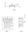
- Fig 7 is a schematic diagram illustrating a user interface device of the user interface device 9 of Fig 2 according to one embodiment.
- the user interface device 9 comprises a plurality of operation indicators 35a-e, an optional display 37 and an alphanumeric keypad 36.
- the operation indicators 35a-e can for instance indicate when access is allowed, access is denied, or that a code sequence needs to be entered on the keypad.
- the operation indicators 35a-e can be provided using different coloured lights and/or different symbols.
- operation indicators using green and red are provided at either end of the set of operation indicators.
- the first operation indicator 35a can be red and the last operation indicator 35e can be green, or vice versa.
- a green operation indicator can indicate that an intrusion detection system is disarmed and a red operation indicator can indicate that an intrusion detection system is armed.
- Fig 7 illustrates five operation indicators 35a-e, any suitable number of operation indicators can be provided.
- the display 37 is used to convey configurable information to the user.
- the display 37 is used to, upon granted access, display until how long the electronic access key is valid, e.g. en end validity date.
- the reader device 1 is integrated with the user interface device 9.
- Fig 8 is a schematic side view of the user interface device 9 of Figs 1 and 7 according to one embodiment. It is here shown how a cable 45 connects the user interface device 9 with other components of the system (see Fig 1 ).
- the cable 45 is guided by a frame 41. In the space behind the frame 41, any excess cable can be stored. In this way, installation of an outer shell 40 can be done after the cable 45 is provided in a suitable way, which simplifies installation of the user interface device.
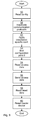
- Fig 9 is a flow chart illustrating one embodiment of a method performed in the reader device of Fig 1 and 2 .
- a read config step 50 configuration data is read from an electronic configuration key.
- an inactivate electronic access key protocol step 52 one or more electronic access key protocols in the reader device are inactivated based on the configuration data.
- an installation specific installation is applied for at least one electronic access key protocol, based on the configuration data. This can be used to improve and customise the security from the generic configuration.
- a configuration period (see 30 of Fig 6 ) is ended at a time which is a configuration duration after when the reader device 1 is powered up. In this way, the inactivate electronic access key protocol step 52 is only performed during the configuration period.
- a read access data step 54 access data is read from an electronic access key. This step can be performed a significant amount of time after the previous steps.
- a send access data step 56 the reader device sends the access data, e.g. to the local control unit.
- the local control unit can determine, based on the access data read from the electronic access key, whether the electronic access key is eligible to gain access to the electronically controlled physical lock.
- the electronically controlled physical lock is set in the unlocked state. Otherwise, the electronically controlled physical lock is set (or remains) in the locked state.
- the method can repeat the read access data step 54 and send access data step 56 as necessary, in a normal operation mode of the reader device.
- reset data is read from an electronic reset key.
- the reading of the reset data comprises using an electronic access key protocol which is supported by the reader device and which has previously been inactivated.
- the reader device is conditionally reset based on the reset data, i.e. when the reset data is considered to be valid reset data. In this way, all of the supported plurality of electronic access key protocols are enabled in the reader device to allow reconfiguration of the reader device.
Landscapes
- Physics & Mathematics (AREA)
- General Physics & Mathematics (AREA)
- Engineering & Computer Science (AREA)
- Computer Networks & Wireless Communication (AREA)
- Lock And Its Accessories (AREA)
Abstract
Description
- The invention relates to a reader device arranged to determine access rights of an electronic access key.
- It is known to use near field wireless access keys to allow or deny access to physical locks, controlling whether it is possible to open a door or not. In such systems, reader devices are used on the lock side to read access information stored on the near field wireless access keys.
- There are many different protocols used for reading the access information. Hence, reader devices need to be appropriate for the correct protocol or protocols to be used in a particular installation.
- It would be greatly beneficial if there were a way to simplify the installation of reader devices.
- It is an object to simplify installation of reader devices.
- According to a first aspect, it is presented a reader device arranged to read access rights of an electronic access key for gaining access to open an electronically controlled physical lock. The reader device supports a plurality of electronic access key protocols and the reader device comprises: a near field radio frequency communication device arranged to read configuration data from an electronic configuration key; a controller arranged to inactivate at least one electronic access key protocol in the reader device based on the configuration data; wherein the near field radio frequency communication device is further arranged to read access data from an electronic access key; and the reader device is arranged to send the access data to a controller unit for determining whether the electronic access key is eligible to open the electronically controlled physical lock.
- By using the electronic configuration key, the configuration of the reader device is effected using only local communication. This is a more secure way to configure the reader device compared to e.g. remote configuration from a central administration node. After installation, the electronic configuration key could e.g. be locked away in a safe location such as a safe. Moreover, this reader device could be provided with a great amount of electronic access key protocols enabled from the start, and the reader device is then configured by inactivating protocols which are not to be used, using the electronic configuration key. In this way, an installation operator could e.g. have a stock of generic, unconfigured, multiprotocol reader devices in stock. This reduces or even eliminates the need to keep installation specific reader devices. These generic reader devices are then easily configured for a particular installation by simply using an electronic configuration key, without any need of the reader device being connected to any external devices; it is sufficient that the reader device is only connected to power.
- In one embodiment, the reader device is only responsive to configuration data during a configuration period, the configuration period ending a configuration duration after when the reader device is powered up. This reduces the risk of random people being able to reconfigure the lock, e.g. to circumvent access control of the reader device.
- The configuration data may comprise a communication control command section and a communication control parameter section. In this way, a configuration specific to a particular installation site can be achieved.
- The controller may be further arranged to apply an installation specific configuration for at least one electronic access key protocol, based on the configuration data. Installation specific is here to be interpreted as specific to a specific installation, such as a site or a company. In this way, security can be improved and/or customised compared to the generic configuration of the reader device.
- The near field radio frequency communication device is further arranged to read reset data from an electronic reset key; and the controller may be arranged to reset the reader device based on the reset data, to thereby enable all of the supported plurality of electronic access key protocols in the reader device. By resetting the radio device, the reader device can again be set in a generic mode, allowing a new configuration to be applied. This can e.g. be useful in the case of a changed configuration of an existing installation (such as due to an upgrade to a more secure protocol) or for reuse of the reader device in another installation.
- The electronic reset key may support an electronic access key protocol which is supported by the reader device and which has not been inactivated. In other words, it is here ensured that the reader device is able to read the electronic reset key without any need of modification.
- The near field radio frequency communication device may be operable around a centre frequency of 13.56 MHZ.
- According to a second aspect, it is presented a method for reading access rights of an electronic access key for gaining access to open an electronically controlled physical lock. The method is performed in a reader device supporting a plurality of electronic access key protocols. The method comprises the steps of: reading configuration data from an electronic configuration key; inactivating at least one electronic access key protocol in the reader device based on the configuration data; reading access data from an electronic access key; and sending the access data to a controller unit for determining whether the electronic access key is eligible to open the electronically controlled physical lock.
- The method may further comprise the step of ending a configuration period at a time being a configuration duration after when the reader device is powered up; and wherein the step of inactivating is only performed during the configuration period.
- The configuration data may comprise a communication control command section and a communication control parameter section.
- The method may further comprise the step, after the step of reading the configuration data, of: applying an installation specific configuration for at least one electronic access key protocol, based on the configuration data.
- The method may further comprise the steps of: reading reset data from an electronic reset key; and resetting the reader device based on the reset data, to thereby enable all of the supported plurality of electronic access key protocols in the reader device.
- The step of reading the reset data may comprise using an electronic access key protocol which is supported by the reader device and which has not been inactivated.
- The step of reading the configuration data and the step of reading the data may comprise reading around a centre frequency of 13.56 MHZ.
- It is to be noted that the term "electronic access key protocol", whenever used in the claims or description of this document, is to be interpreted as a way in which a reader device reads data from an electronic access key.
- Generally, all terms used in the claims are to be interpreted according to their ordinary meaning in the technical field, unless explicitly defined otherwise herein. All references to "a/an/the element, apparatus, component, means, step, etc." are to be interpreted openly as referring to at least one instance of the element, apparatus, component, means, step, etc., unless explicitly stated otherwise. The steps of any method disclosed herein do not have to be performed in the exact order disclosed, unless explicitly stated.
- The invention is now described, by way of example, with reference to the accompanying drawings, in which:
-
Fig 1 is a schematic diagram illustrating an environment where embodiments presented herein can be applied; -
Fig 2 is a schematic diagram illustrating a reader device ofFig 1 and its communication with various electronic keys according to one embodiment; -
Fig 3 is a schematic diagram illustrating an electronic configuration key ofFig 2 according to one embodiment; -
Fig 4 is a schematic diagram illustrating an electronic reset key ofFig 2 according to one embodiment; -
Fig 5 is a schematic diagram illustrating an electronic configuration key ofFig 2 according to one embodiment; -
Fig 6 is a schematic graph illustrating operation of the reader device ofFigs 1 and 2 according to one embodiment; -
Fig 7 is a schematic diagram illustrating a user interface device of the reader device ofFig 2 according to one embodiment; -
Fig 8 is a schematic side view of the user interface device ofFig 7 according to one embodiment; and -
Fig 9 is a flow chart illustrating one embodiment of a method performed in the reader device ofFig 1 and 2 . - The invention will now be described more fully hereinafter with reference to the accompanying drawings, in which certain embodiments of the invention are shown. This invention may, however, be embodied in many different forms and should not be construed as limited to the embodiments set forth herein; rather, these embodiments are provided by way of example so that this disclosure will be thorough and complete, and will fully convey the scope of the invention to those skilled in the art. Like numbers refer to like elements throughout the description.
-
Fig 1 is a schematic diagram illustrating a system where embodiments presented herein can be applied. An electronically controlledphysical lock 8 is controlled by alocal control unit 7. Optionally, the electronically controlledphysical lock 8 can also be controlled by a conventional mechanical key. - A
reader device 1 communicates with anelectronic access key 10, in possession of a user, using near field radio frequency communication. Auser interface device 9 allows the user to input data into and read data from the system. - The electronically controlled
physical lock 8 is controllable by thelocal control unit 7 to be in a locked or unlocked state, depending on theelectronic access key 10. In this way, access to a physical space can be controlled. For example a door can be controlled to be able to be opened when the electronically controlledphysical lock 8 is in an unlocked state and not to be able to be opened when the electronically controlledphysical lock 8 is in a locked state. Optionally, thelocal control unit 7 is configured to use additional security measures to gain access, e.g. by requiring a code to be entered using theuser interface device 9 or using biometrics. - A
central control unit 5 enables administration of the system and can configure one or morelocal control units 7. In one embodiment, the central control unit allows thereader device 1 to receive software upgrades remotely. As explained in more detail below, thereader device 1 can subsequently be configured to make use of the software upgrade, e.g. to use a new electronic access key protocol, using an electronic configuration key readable by thereader device 1. - Each
local control unit 7 can e.g. be a computer with a central processing unit, memory, input/output unit(s), etc. The communication between thelocal control unit 7,user interface device 9,reader device 1 and the electronically controlledphysical lock 8 can occur using any suitable electronic access key protocol, e.g. using a controller area network (CAN) bus, Ethernet, universal serial bus (USB), serial connections (e.g. RS-232, RS-422, etc.) and/or parallel connections (e.g. Centronics). - The communication between the
local control unit 7 and thecentral control unit 5 can e.g. occur using a wide area protocol such as Internet Protocol (IP), whereby thelocal control unit 7 and the central control unit can be situated in remote locations far from each other and can e.g. communicate via the Internet (e.g. using an encrypted connection). - The
central control unit 5 can e.g. be a general purpose computer with display, keyboard, etc., with appropriate software installed, allowing an operator to configure one or more connected local control unit, e.g. belonging to one company or installation. - The
local control unit 7,user interface device 9,reader device 1, and electronically controllablephysical lock 8 can be e.g. powered by a connection to a mains AC (alternating current) source, optionally via a chargeable backup power storage device such as a rechargeable battery. - Optionally, one or more of the
local control unit 7,user interface device 9,reader device 1, and electronically controllablephysical lock 8 can be combined in a single physical device. -
Fig 2 is a schematic diagram illustrating areader device 1 ofFig 1 and its communication with various electronic keys 10-12 according to one embodiment. Thereader device 1 comprises acontroller 4 using any combination of one or more of a suitable central processing unit (CPU), multiprocessor, microcontroller, digital signal processor (DSP), application specific integrated circuit (ASIC), field programmable gate array (FPGA) etc., capable of execution inherent to thecontroller 4 and/or according to software instructions stored in acomputer program product 6. Thecomputer program product 6 is memory being any combination of read and write memory (RAM) and read only memory (ROM). The memory comprises persistent storage, which, for example, can be any single one or combination of magnetic memory, optical memory, solid state memory or even remotely mounted memory. - The
controller 4 can be configured to execute the method described with reference toFig 9 below. - The
reader device 1 also comprises a near field radiofrequency communication device 3 arranged to communicate with one or more of electronic keys 10-12 using near field communication. Near field is here to interpreted as a distance between the reader and the electronic key where electric and magnetic components produced directly by currents and charge-separations dominate. Thereader device 1 supports a plurality of electronic access key protocols. However, as explained in more detail below, one or more electronic access key protocols can be inactivated using anelectronic configuration key 11. The near field radiofrequency communication device 3 comprises appropriate transmitter and receiver circuitry to read data from a nearby electronic key 10-12. For example, the near field radiofrequency communication device 3 can comprise circuitry to send a signal to the electronic key 10-12 which energises the electronic key such that data stored on the electronic key is sent to and received by the near field radiofrequency communication device 3. - Using the near field radio
frequency communication device 3, thereader device 1 can communicate with anelectronic access key 10, anelectronic configuration key 11 and/or an electronic reset key. As explained above, theelectronic access key 10 is read by thereader device 1, and evaluated by thelocal control unit 7 to allow or deny access. Thelocal control unit 7 is thus arranged to determine, based on access data read from theelectronic access key 10, whether theelectronic access key 10 is eligible to open the electronically controlledphysical lock 8. - Furthermore, the near field radio
frequency communication device 3 is arranged to read configuration data from anelectronic configuration key 11. Thecontroller 4 is arranged to inactivate electronic access key protocol in the reader device based on theconfiguration data 20. Moreover, installation specific configuration can be applied. This is explained in more detail with reference toFig 6 below. - Optionally, the near field radio
frequency communication device 3 is further arranged to read reset data from anelectronic reset key 12. Based on the reset data, thecontroller 4 is arranged to conditionally reset the reader device, to thereby enable all of the supported plurality of electronic access key protocols in the reader device. Also, the reset can optionally remove any installation specific configuration to thereby reset the reader device to a generic state. For example, thereader device 1 can support any combination of the following protocols using 13.56 MHz centre frequency (in effect 13.553 MHZ to 13.567 MHZ): MIFARE Classic, MIFARE Ultralight, MIFARE Ultralight EV1, MIFARE Ultralight C, MIFARE DESFire, MIFARE DESFire EV1, MIFARE Plus, MIFARE sam av2, and Near Field Communication (NFC). -
Fig 3 is a schematic diagram illustrating anelectronic configuration key 11 ofFig 2 according to one embodiment. Theelectronic configuration key 11 comprises amemory 15 holdingconfiguration data 20 which, when read by a reader device in a configuration period, makes thereader device 1 inactivate one or more electronic access key protocols. Moreover, theconfiguration data 20 can control how the electronic access key protocol is to function, e.g. which sectors to read on the electronic access key, etc. Optionally, theconfiguration data 20 comprises a communicationcontrol command section 21 and a communicationcontrol parameter section 22. Theelectronic configuration key 11 can use any protocol supported by thereader device 1. Theelectronic configuration key 11 supports one of the electronic access key protocol used by the reader device. -
Fig 4 is a schematic diagram illustrating anelectronic reset key 12 ofFig 2 according to one embodiment. Theelectronic reset key 12 comprises a memory 15' holding resetdata 25 which, when read by a reader device in a configuration period, makes thereader device 1 inactivate one or more electronic access key protocols. Since theelectronic reset key 12 is used to reset the reader device, it supports an electronic access key protocol which an, already configured reader device, is configured to support. -
Fig 5 is a schematic diagram illustrating anelectronic access key 10 ofFig 2 according to one embodiment. Theelectronic access key 10 comprises amemory 15" holdingaccess data 26 which, when read by a reader device in a configuration period, allows the reader device determine whether to grant or deny access. Theelectronic access key 10 supports an electronic access key protocol which is supported by thereader device 1. -
Fig 6 is a schematic graph illustrating operation of thereader device 1 ofFigs 1 and 2 according to one embodiment. At time to, the reader device is powered up. During aconfiguration period 30, the reader device is arranged to read anyelectronic configuration key 11 provided within range of the near field radiofrequency communication device 3. The configuration period ends at time t1, which is a configuration duration after the power on time to. The configuration duration represents an amount of time (e.g. a certain number of seconds) and can e.g. be a parameter which is stored in the reader device. - After the time t1, the
reader device 1 is in anormal operation period 31 and grants or denies access using the electronically controlled physical lock in dependence on what electronica access keys are provided in the vicinity of its near field radiofrequency communication device 3. - Optionally, the reader device is also only responsive to electronic reset keys in the
configuration period 30, and not during thenormal operation period 31. - Using the
configuration period 30, a greater degree of security is provided, since a configuration, and optionally reset, of the reader device using appropriate electronic keys can only be performed during a relatively short period. This reduces the risk of unauthorised attempts to configure and/or reset thereader device 1, e.g. to gain unlawful access to a physical space. -
Fig 7 is a schematic diagram illustrating a user interface device of theuser interface device 9 ofFig 2 according to one embodiment. Theuser interface device 9 comprises a plurality ofoperation indicators 35a-e, anoptional display 37 and analphanumeric keypad 36. - The
operation indicators 35a-e can for instance indicate when access is allowed, access is denied, or that a code sequence needs to be entered on the keypad. Theoperation indicators 35a-e can be provided using different coloured lights and/or different symbols. In one embodiment, operation indicators using green and red are provided at either end of the set of operation indicators. For example, thefirst operation indicator 35a can be red and thelast operation indicator 35e can be green, or vice versa. In this way, there is less risk of colour blind users confusing a green operation indicator for a red operation indicator or vice versa, since the user will eventually learn from experience which end corresponds to which coloured operation indicator. For example, a green operation indicator can indicate that an intrusion detection system is disarmed and a red operation indicator can indicate that an intrusion detection system is armed. WhileFig 7 illustrates fiveoperation indicators 35a-e, any suitable number of operation indicators can be provided. - The
display 37 is used to convey configurable information to the user. In one embodiment, thedisplay 37 is used to, upon granted access, display until how long the electronic access key is valid, e.g. en end validity date. - Optionally, the
reader device 1 is integrated with theuser interface device 9. -
Fig 8 is a schematic side view of theuser interface device 9 ofFigs 1 and7 according to one embodiment. It is here shown how acable 45 connects theuser interface device 9 with other components of the system (seeFig 1 ). Thecable 45 is guided by aframe 41. In the space behind theframe 41, any excess cable can be stored. In this way, installation of anouter shell 40 can be done after thecable 45 is provided in a suitable way, which simplifies installation of the user interface device. -
Fig 9 is a flow chart illustrating one embodiment of a method performed in the reader device ofFig 1 and 2 . - In a read config step 50, configuration data is read from an electronic configuration key.
- In an inactivate electronic access
key protocol step 52, one or more electronic access key protocols in the reader device are inactivated based on the configuration data. - In an optional apply installation specific configuration step (51) an installation specific installation is applied for at least one electronic access key protocol, based on the configuration data. This can be used to improve and customise the security from the generic configuration.
- In an optional end configuration period step 53, a configuration period (see 30 of
Fig 6 ) is ended at a time which is a configuration duration after when thereader device 1 is powered up. In this way, the inactivate electronic accesskey protocol step 52 is only performed during the configuration period. - In a read
access data step 54, access data is read from an electronic access key. This step can be performed a significant amount of time after the previous steps. - In a send
access data step 56, the reader device sends the access data, e.g. to the local control unit. Thereby, the local control unit can determine, based on the access data read from the electronic access key, whether the electronic access key is eligible to gain access to the electronically controlled physical lock. When access is granted, the electronically controlled physical lock is set in the unlocked state. Otherwise, the electronically controlled physical lock is set (or remains) in the locked state. The method can repeat the read access data step 54 and send access data step 56 as necessary, in a normal operation mode of the reader device. - In an optional read reset
data step 58, reset data is read from an electronic reset key. The reading of the reset data comprises using an electronic access key protocol which is supported by the reader device and which has previously been inactivated. - In an optional reset
reader device step 60, the reader device is conditionally reset based on the reset data, i.e. when the reset data is considered to be valid reset data. In this way, all of the supported plurality of electronic access key protocols are enabled in the reader device to allow reconfiguration of the reader device. - The invention has mainly been described above with reference to a few embodiments. However, as is readily appreciated by a person skilled in the art, other embodiments than the ones disclosed above are equally possible within the scope of the invention, as defined by the appended patent claims.
Claims (14)
- A reader device (1) arranged to read access rights of an electronic access key (10) for gaining access to open an electronically controlled physical lock (8), the reader device (1) supporting a plurality of electronic access key protocols and the reader device (1) comprising:a near field radio frequency communication device (3) arranged to read configuration data (20) from an electronic configuration key (11);a controller (4) arranged to inactivate at least one electronic access key protocol in the reader device based on the configuration data (20);wherein the near field radio frequency communication device (3) is further arranged to read access data (26) from an electronic access key (10); and the reader device is arranged to send the access data (26) to a controller unit for determining whether the electronic access key (10) is eligible to open the electronically controlled physical lock (8).
- The reader device (1) according to claim 1, wherein the reader device (1) is only responsive to configuration data during a configuration period, the configuration period ending a configuration duration after when the reader device (1) is powered up.
- The reader device (1) according to any one of the preceding claims, wherein the configuration data (20) comprises a communication control command section (21) and a communication control parameter section (22).
- The reader device (1) according to any one of the preceding claims, wherein the controller (4) is further arranged to apply an installation specific configuration for at least one electronic access key protocol, based on the configuration data (20).
- The reader device (1) according to any one of the preceding claims, wherein the near field radio frequency communication device (3) is further arranged to read reset data from an electronic reset key (12); and
the controller (4) is arranged to reset the reader device based on the reset data, to thereby enable all of the supported plurality of electronic access key protocols in the reader device. - The reader device (1) according to claim 5, wherein the electronic reset key (12) supports an electronic access key protocol which is supported by the reader device (1) and which has not been inactivated.
- The reader device (1) according to any one of the preceding claims, wherein the near field radio frequency communication device (3) is operable around a centre frequency of 13.56 MHZ.
- A method for reading access rights of an electronic access key (10) for gaining access to open an electronically controlled physical lock (8), the method being performed in a reader device (1) supporting a plurality of electronic access key protocols, the method comprising the steps of:reading (50) configuration data (20) from an electronic configuration key (11);inactivating (52) at least one electronic access key protocol in the reader device based on the configuration data (20);reading (54) access data (26) from an electronic access key (10); andsending (56) the access data (26) to a controller unit for determining whether the electronic access key (10) is eligible to open the electronically controlled physical lock (8).
- The method according to claim 8, further comprising the step of ending (53) a configuration period at a time being a configuration duration after when the reader device (1) is powered up; and wherein the step of inactivating (52) is only performed during the configuration period.
- The method according claim 8 or 9, wherein the configuration data (20) comprises a communication control command section (21) and a communication control parameter section (22).
- The method according to any one of claims 8 to 10, further comprising the step, after the step of reading the configuration data, of:applying (51) an installation specific configuration for at least one electronic access key protocol, based on the configuration data (20).
- The method according to any one of claims 8 to 11, further comprising the steps of:reading (58) reset data from an electronic reset key (12); andresetting (60) the reader device (1) based on the reset data, to thereby enable all of the supported plurality of electronic access key protocols in the reader device.
- The method according to claim 12, wherein the step of reading (58) the reset data comprises using an electronic access key protocol which is supported by the reader device (1) and which has not been inactivated.
- The method according to any one of claims 8 to 13, wherein the step of reading the configuration data (50) and the step of reading the data (54) comprises reading around a centre frequency of 13.56 MHZ.
Applications Claiming Priority (1)
| Application Number | Priority Date | Filing Date | Title |
|---|---|---|---|
| SE1350544A SE539039C2 (en) | 2013-05-03 | 2013-05-03 | Reader device for an electronic access key for a lock and method for configuring a reader device |
Publications (3)
| Publication Number | Publication Date |
|---|---|
| EP2800067A2 true EP2800067A2 (en) | 2014-11-05 |
| EP2800067A3 EP2800067A3 (en) | 2018-01-03 |
| EP2800067B1 EP2800067B1 (en) | 2022-05-04 |
Family
ID=50440580
Family Applications (1)
| Application Number | Title | Priority Date | Filing Date |
|---|---|---|---|
| EP14164004.5A Active EP2800067B1 (en) | 2013-05-03 | 2014-04-09 | Reader device and associated method |
Country Status (2)
| Country | Link |
|---|---|
| EP (1) | EP2800067B1 (en) |
| SE (1) | SE539039C2 (en) |
Cited By (1)
| Publication number | Priority date | Publication date | Assignee | Title |
|---|---|---|---|---|
| EP3182384A1 (en) * | 2015-12-17 | 2017-06-21 | Axis AB | Improved physical access control system |
Family Cites Families (4)
| Publication number | Priority date | Publication date | Assignee | Title |
|---|---|---|---|---|
| US7376839B2 (en) * | 2001-05-04 | 2008-05-20 | Cubic Corporation | Smart card access control system |
| US7706778B2 (en) * | 2005-04-05 | 2010-04-27 | Assa Abloy Ab | System and method for remotely assigning and revoking access credentials using a near field communication equipped mobile phone |
| EP2332386A4 (en) * | 2008-09-30 | 2014-07-23 | Honeywell Int Inc | Systems and methods for interacting with access control devices |
| DE102011054637B4 (en) * | 2011-10-20 | 2025-01-23 | Marc Gaston Zacher | Procedure for configuring an electromechanical lock |
-
2013
- 2013-05-03 SE SE1350544A patent/SE539039C2/en unknown
-
2014
- 2014-04-09 EP EP14164004.5A patent/EP2800067B1/en active Active
Non-Patent Citations (1)
| Title |
|---|
| None |
Cited By (6)
| Publication number | Priority date | Publication date | Assignee | Title |
|---|---|---|---|---|
| EP3182384A1 (en) * | 2015-12-17 | 2017-06-21 | Axis AB | Improved physical access control system |
| CN106897750A (en) * | 2015-12-17 | 2017-06-27 | 安讯士有限公司 | Improved physical access control system |
| EP3182384B1 (en) | 2015-12-17 | 2017-11-29 | Axis AB | Improved physical access control system |
| US9852557B2 (en) | 2015-12-17 | 2017-12-26 | Axis Ab | Physical access control system |
| CN106897750B (en) * | 2015-12-17 | 2018-08-07 | 安讯士有限公司 | Improved physical access control system |
| EP3182384B2 (en) † | 2015-12-17 | 2020-09-23 | Axis AB | Improved physical access control system |
Also Published As
| Publication number | Publication date |
|---|---|
| SE1350544A1 (en) | 2014-11-04 |
| EP2800067B1 (en) | 2022-05-04 |
| EP2800067A3 (en) | 2018-01-03 |
| SE539039C2 (en) | 2017-03-28 |
Similar Documents
| Publication | Publication Date | Title |
|---|---|---|
| CN107667369B (en) | Use of a mobile device with a lock | |
| EP3029906B1 (en) | Authentication system and transmit terminal for authenticating the light signal | |
| EP2973442B1 (en) | Controlling physical access to secure areas via client devices in a networked environment | |
| US11189117B2 (en) | Method and system for controlling a smart lock | |
| US10380815B2 (en) | Transient asset management systems and methods | |
| EP3129569B1 (en) | Temporarily pairing a mobile device with a peripheral device | |
| CN111542027B (en) | Method, system and article for controlling safety equipment | |
| CN107466463A (en) | Remote monitoring and control system for barrier operators | |
| US20210099880A1 (en) | Technologies for access control communications | |
| CN104581726A (en) | An authentication method and system | |
| EP3291184B1 (en) | Resetting access to an access object | |
| TWI902810B (en) | Apparatus to electronic control locking devices and method for operating the same | |
| WO2019060834A1 (en) | Peripheral controller in an access control system | |
| US11151240B2 (en) | Access key card that cancels automatically for safety and security | |
| EP3714363A1 (en) | Upgrade of network equipment | |
| WO2017021408A1 (en) | Secure mobile access for automation systems | |
| US9779566B2 (en) | Resource management based on physical authentication and authorization | |
| CA3006190C (en) | Electric lock and control method thereof | |
| EP4027309A1 (en) | Universal smart interface for electronic locks | |
| EP2800067B1 (en) | Reader device and associated method | |
| CN110827449A (en) | Intelligent door lock control system and control method | |
| JP2016095740A (en) | Gateway device, communication system, information change control method, and information change control program | |
| US10467830B2 (en) | Electronic credential reader | |
| CN113763603B (en) | Information processing device, method, computer-readable storage medium and portable terminal | |
| KR102361081B1 (en) | Method and system for managing kiosk based on programmable logic controller |
Legal Events
| Date | Code | Title | Description |
|---|---|---|---|
| PUAI | Public reference made under article 153(3) epc to a published international application that has entered the european phase |
Free format text: ORIGINAL CODE: 0009012 |
|
| 17P | Request for examination filed |
Effective date: 20140409 |
|
| AK | Designated contracting states |
Kind code of ref document: A2 Designated state(s): AL AT BE BG CH CY CZ DE DK EE ES FI FR GB GR HR HU IE IS IT LI LT LU LV MC MK MT NL NO PL PT RO RS SE SI SK SM TR |
|
| AX | Request for extension of the european patent |
Extension state: BA ME |
|
| RIN1 | Information on inventor provided before grant (corrected) |
Inventor name: BLOMQVIST, FREDRIK Inventor name: SEVALLIUS, PATRIK Inventor name: BOVIN, PERLA Inventor name: BERGLUND, JENS Inventor name: JOHANSSON KJERSTAD, OVE |
|
| PUAL | Search report despatched |
Free format text: ORIGINAL CODE: 0009013 |
|
| AK | Designated contracting states |
Kind code of ref document: A3 Designated state(s): AL AT BE BG CH CY CZ DE DK EE ES FI FR GB GR HR HU IE IS IT LI LT LU LV MC MK MT NL NO PL PT RO RS SE SI SK SM TR |
|
| AX | Request for extension of the european patent |
Extension state: BA ME |
|
| RIC1 | Information provided on ipc code assigned before grant |
Ipc: G07C 9/00 20060101AFI20171124BHEP |
|
| STAA | Information on the status of an ep patent application or granted ep patent |
Free format text: STATUS: REQUEST FOR EXAMINATION WAS MADE |
|
| R17P | Request for examination filed (corrected) |
Effective date: 20180709 |
|
| RBV | Designated contracting states (corrected) |
Designated state(s): AL AT BE BG CH CY CZ DE DK EE ES FI FR GB GR HR HU IE IS IT LI LT LU LV MC MK MT NL NO PL PT RO RS SE SI SK SM TR |
|
| STAA | Information on the status of an ep patent application or granted ep patent |
Free format text: STATUS: EXAMINATION IS IN PROGRESS |
|
| 17Q | First examination report despatched |
Effective date: 20200525 |
|
| RAP1 | Party data changed (applicant data changed or rights of an application transferred) |
Owner name: ASSA ABLOY OPENING SOLUTIONS SWEDEN AB |
|
| GRAP | Despatch of communication of intention to grant a patent |
Free format text: ORIGINAL CODE: EPIDOSNIGR1 |
|
| STAA | Information on the status of an ep patent application or granted ep patent |
Free format text: STATUS: GRANT OF PATENT IS INTENDED |
|
| INTG | Intention to grant announced |
Effective date: 20211125 |
|
| GRAS | Grant fee paid |
Free format text: ORIGINAL CODE: EPIDOSNIGR3 |
|
| GRAA | (expected) grant |
Free format text: ORIGINAL CODE: 0009210 |
|
| STAA | Information on the status of an ep patent application or granted ep patent |
Free format text: STATUS: THE PATENT HAS BEEN GRANTED |
|
| RIN1 | Information on inventor provided before grant (corrected) |
Inventor name: JOHANSSON KJERSTAD, OVE Inventor name: BLOMQVIST, FREDRIK Inventor name: SEVALLIUS, PATRIK Inventor name: MUNHOZ, PERLA Inventor name: BERGLUND, JENS |
|
| AK | Designated contracting states |
Kind code of ref document: B1 Designated state(s): AL AT BE BG CH CY CZ DE DK EE ES FI FR GB GR HR HU IE IS IT LI LT LU LV MC MK MT NL NO PL PT RO RS SE SI SK SM TR |
|
| REG | Reference to a national code |
Ref country code: GB Ref legal event code: FG4D |
|
| REG | Reference to a national code |
Ref country code: CH Ref legal event code: EP |
|
| REG | Reference to a national code |
Ref country code: AT Ref legal event code: REF Ref document number: 1489930 Country of ref document: AT Kind code of ref document: T Effective date: 20220515 |
|
| REG | Reference to a national code |
Ref country code: DE Ref legal event code: R096 Ref document number: 602014083507 Country of ref document: DE |
|
| REG | Reference to a national code |
Ref country code: IE Ref legal event code: FG4D |
|
| REG | Reference to a national code |
Ref country code: LT Ref legal event code: MG9D |
|
| REG | Reference to a national code |
Ref country code: NL Ref legal event code: MP Effective date: 20220504 |
|
| REG | Reference to a national code |
Ref country code: AT Ref legal event code: MK05 Ref document number: 1489930 Country of ref document: AT Kind code of ref document: T Effective date: 20220504 |
|
| PG25 | Lapsed in a contracting state [announced via postgrant information from national office to epo] |
Ref country code: SE Free format text: LAPSE BECAUSE OF FAILURE TO SUBMIT A TRANSLATION OF THE DESCRIPTION OR TO PAY THE FEE WITHIN THE PRESCRIBED TIME-LIMIT Effective date: 20220504 Ref country code: PT Free format text: LAPSE BECAUSE OF FAILURE TO SUBMIT A TRANSLATION OF THE DESCRIPTION OR TO PAY THE FEE WITHIN THE PRESCRIBED TIME-LIMIT Effective date: 20220905 Ref country code: NO Free format text: LAPSE BECAUSE OF FAILURE TO SUBMIT A TRANSLATION OF THE DESCRIPTION OR TO PAY THE FEE WITHIN THE PRESCRIBED TIME-LIMIT Effective date: 20220804 Ref country code: NL Free format text: LAPSE BECAUSE OF FAILURE TO SUBMIT A TRANSLATION OF THE DESCRIPTION OR TO PAY THE FEE WITHIN THE PRESCRIBED TIME-LIMIT Effective date: 20220504 Ref country code: LT Free format text: LAPSE BECAUSE OF FAILURE TO SUBMIT A TRANSLATION OF THE DESCRIPTION OR TO PAY THE FEE WITHIN THE PRESCRIBED TIME-LIMIT Effective date: 20220504 Ref country code: HR Free format text: LAPSE BECAUSE OF FAILURE TO SUBMIT A TRANSLATION OF THE DESCRIPTION OR TO PAY THE FEE WITHIN THE PRESCRIBED TIME-LIMIT Effective date: 20220504 Ref country code: GR Free format text: LAPSE BECAUSE OF FAILURE TO SUBMIT A TRANSLATION OF THE DESCRIPTION OR TO PAY THE FEE WITHIN THE PRESCRIBED TIME-LIMIT Effective date: 20220805 Ref country code: FI Free format text: LAPSE BECAUSE OF FAILURE TO SUBMIT A TRANSLATION OF THE DESCRIPTION OR TO PAY THE FEE WITHIN THE PRESCRIBED TIME-LIMIT Effective date: 20220504 Ref country code: ES Free format text: LAPSE BECAUSE OF FAILURE TO SUBMIT A TRANSLATION OF THE DESCRIPTION OR TO PAY THE FEE WITHIN THE PRESCRIBED TIME-LIMIT Effective date: 20220504 Ref country code: BG Free format text: LAPSE BECAUSE OF FAILURE TO SUBMIT A TRANSLATION OF THE DESCRIPTION OR TO PAY THE FEE WITHIN THE PRESCRIBED TIME-LIMIT Effective date: 20220804 Ref country code: AT Free format text: LAPSE BECAUSE OF FAILURE TO SUBMIT A TRANSLATION OF THE DESCRIPTION OR TO PAY THE FEE WITHIN THE PRESCRIBED TIME-LIMIT Effective date: 20220504 |
|
| PG25 | Lapsed in a contracting state [announced via postgrant information from national office to epo] |
Ref country code: RS Free format text: LAPSE BECAUSE OF FAILURE TO SUBMIT A TRANSLATION OF THE DESCRIPTION OR TO PAY THE FEE WITHIN THE PRESCRIBED TIME-LIMIT Effective date: 20220504 Ref country code: PL Free format text: LAPSE BECAUSE OF FAILURE TO SUBMIT A TRANSLATION OF THE DESCRIPTION OR TO PAY THE FEE WITHIN THE PRESCRIBED TIME-LIMIT Effective date: 20220504 Ref country code: LV Free format text: LAPSE BECAUSE OF FAILURE TO SUBMIT A TRANSLATION OF THE DESCRIPTION OR TO PAY THE FEE WITHIN THE PRESCRIBED TIME-LIMIT Effective date: 20220504 Ref country code: IS Free format text: LAPSE BECAUSE OF FAILURE TO SUBMIT A TRANSLATION OF THE DESCRIPTION OR TO PAY THE FEE WITHIN THE PRESCRIBED TIME-LIMIT Effective date: 20220904 |
|
| PG25 | Lapsed in a contracting state [announced via postgrant information from national office to epo] |
Ref country code: SM Free format text: LAPSE BECAUSE OF FAILURE TO SUBMIT A TRANSLATION OF THE DESCRIPTION OR TO PAY THE FEE WITHIN THE PRESCRIBED TIME-LIMIT Effective date: 20220504 Ref country code: SK Free format text: LAPSE BECAUSE OF FAILURE TO SUBMIT A TRANSLATION OF THE DESCRIPTION OR TO PAY THE FEE WITHIN THE PRESCRIBED TIME-LIMIT Effective date: 20220504 Ref country code: RO Free format text: LAPSE BECAUSE OF FAILURE TO SUBMIT A TRANSLATION OF THE DESCRIPTION OR TO PAY THE FEE WITHIN THE PRESCRIBED TIME-LIMIT Effective date: 20220504 Ref country code: EE Free format text: LAPSE BECAUSE OF FAILURE TO SUBMIT A TRANSLATION OF THE DESCRIPTION OR TO PAY THE FEE WITHIN THE PRESCRIBED TIME-LIMIT Effective date: 20220504 Ref country code: DK Free format text: LAPSE BECAUSE OF FAILURE TO SUBMIT A TRANSLATION OF THE DESCRIPTION OR TO PAY THE FEE WITHIN THE PRESCRIBED TIME-LIMIT Effective date: 20220504 Ref country code: CZ Free format text: LAPSE BECAUSE OF FAILURE TO SUBMIT A TRANSLATION OF THE DESCRIPTION OR TO PAY THE FEE WITHIN THE PRESCRIBED TIME-LIMIT Effective date: 20220504 |
|
| REG | Reference to a national code |
Ref country code: DE Ref legal event code: R097 Ref document number: 602014083507 Country of ref document: DE |
|
| PLBE | No opposition filed within time limit |
Free format text: ORIGINAL CODE: 0009261 |
|
| STAA | Information on the status of an ep patent application or granted ep patent |
Free format text: STATUS: NO OPPOSITION FILED WITHIN TIME LIMIT |
|
| PG25 | Lapsed in a contracting state [announced via postgrant information from national office to epo] |
Ref country code: AL Free format text: LAPSE BECAUSE OF FAILURE TO SUBMIT A TRANSLATION OF THE DESCRIPTION OR TO PAY THE FEE WITHIN THE PRESCRIBED TIME-LIMIT Effective date: 20220504 |
|
| 26N | No opposition filed |
Effective date: 20230207 |
|
| PG25 | Lapsed in a contracting state [announced via postgrant information from national office to epo] |
Ref country code: SI Free format text: LAPSE BECAUSE OF FAILURE TO SUBMIT A TRANSLATION OF THE DESCRIPTION OR TO PAY THE FEE WITHIN THE PRESCRIBED TIME-LIMIT Effective date: 20220504 |
|
| REG | Reference to a national code |
Ref country code: CH Ref legal event code: PL |
|
| PG25 | Lapsed in a contracting state [announced via postgrant information from national office to epo] |
Ref country code: LU Free format text: LAPSE BECAUSE OF NON-PAYMENT OF DUE FEES Effective date: 20230409 |
|
| REG | Reference to a national code |
Ref country code: BE Ref legal event code: MM Effective date: 20230430 |
|
| PG25 | Lapsed in a contracting state [announced via postgrant information from national office to epo] |
Ref country code: MC Free format text: LAPSE BECAUSE OF FAILURE TO SUBMIT A TRANSLATION OF THE DESCRIPTION OR TO PAY THE FEE WITHIN THE PRESCRIBED TIME-LIMIT Effective date: 20220504 |
|
| PG25 | Lapsed in a contracting state [announced via postgrant information from national office to epo] |
Ref country code: MC Free format text: LAPSE BECAUSE OF FAILURE TO SUBMIT A TRANSLATION OF THE DESCRIPTION OR TO PAY THE FEE WITHIN THE PRESCRIBED TIME-LIMIT Effective date: 20220504 Ref country code: LI Free format text: LAPSE BECAUSE OF NON-PAYMENT OF DUE FEES Effective date: 20230430 Ref country code: IT Free format text: LAPSE BECAUSE OF FAILURE TO SUBMIT A TRANSLATION OF THE DESCRIPTION OR TO PAY THE FEE WITHIN THE PRESCRIBED TIME-LIMIT Effective date: 20220504 Ref country code: CH Free format text: LAPSE BECAUSE OF NON-PAYMENT OF DUE FEES Effective date: 20230430 |
|
| REG | Reference to a national code |
Ref country code: IE Ref legal event code: MM4A |
|
| PG25 | Lapsed in a contracting state [announced via postgrant information from national office to epo] |
Ref country code: BE Free format text: LAPSE BECAUSE OF NON-PAYMENT OF DUE FEES Effective date: 20230430 |
|
| PG25 | Lapsed in a contracting state [announced via postgrant information from national office to epo] |
Ref country code: IE Free format text: LAPSE BECAUSE OF NON-PAYMENT OF DUE FEES Effective date: 20230409 |
|
| PG25 | Lapsed in a contracting state [announced via postgrant information from national office to epo] |
Ref country code: IE Free format text: LAPSE BECAUSE OF NON-PAYMENT OF DUE FEES Effective date: 20230409 |
|
| PG25 | Lapsed in a contracting state [announced via postgrant information from national office to epo] |
Ref country code: BG Free format text: LAPSE BECAUSE OF FAILURE TO SUBMIT A TRANSLATION OF THE DESCRIPTION OR TO PAY THE FEE WITHIN THE PRESCRIBED TIME-LIMIT Effective date: 20220504 |
|
| PG25 | Lapsed in a contracting state [announced via postgrant information from national office to epo] |
Ref country code: BG Free format text: LAPSE BECAUSE OF FAILURE TO SUBMIT A TRANSLATION OF THE DESCRIPTION OR TO PAY THE FEE WITHIN THE PRESCRIBED TIME-LIMIT Effective date: 20220504 |
|
| PGFP | Annual fee paid to national office [announced via postgrant information from national office to epo] |
Ref country code: FR Payment date: 20250321 Year of fee payment: 12 |
|
| PGFP | Annual fee paid to national office [announced via postgrant information from national office to epo] |
Ref country code: GB Payment date: 20250313 Year of fee payment: 12 |
|
| PGFP | Annual fee paid to national office [announced via postgrant information from national office to epo] |
Ref country code: DE Payment date: 20250311 Year of fee payment: 12 |
|
| PG25 | Lapsed in a contracting state [announced via postgrant information from national office to epo] |
Ref country code: CY Free format text: LAPSE BECAUSE OF FAILURE TO SUBMIT A TRANSLATION OF THE DESCRIPTION OR TO PAY THE FEE WITHIN THE PRESCRIBED TIME-LIMIT; INVALID AB INITIO Effective date: 20140409 |
|
| PG25 | Lapsed in a contracting state [announced via postgrant information from national office to epo] |
Ref country code: HU Free format text: LAPSE BECAUSE OF FAILURE TO SUBMIT A TRANSLATION OF THE DESCRIPTION OR TO PAY THE FEE WITHIN THE PRESCRIBED TIME-LIMIT; INVALID AB INITIO Effective date: 20140409 |
|
| PG25 | Lapsed in a contracting state [announced via postgrant information from national office to epo] |
Ref country code: TR Free format text: LAPSE BECAUSE OF FAILURE TO SUBMIT A TRANSLATION OF THE DESCRIPTION OR TO PAY THE FEE WITHIN THE PRESCRIBED TIME-LIMIT Effective date: 20220504 |