EP2799861B1 - Ultrasonic component inspection apparatus and method with a conformable guide member - Google Patents
Ultrasonic component inspection apparatus and method with a conformable guide member Download PDFInfo
- Publication number
- EP2799861B1 EP2799861B1 EP13165902.1A EP13165902A EP2799861B1 EP 2799861 B1 EP2799861 B1 EP 2799861B1 EP 13165902 A EP13165902 A EP 13165902A EP 2799861 B1 EP2799861 B1 EP 2799861B1
- Authority
- EP
- European Patent Office
- Prior art keywords
- component
- guide member
- guide
- shape
- ultrasonic waves
- Prior art date
- Legal status (The legal status is an assumption and is not a legal conclusion. Google has not performed a legal analysis and makes no representation as to the accuracy of the status listed.)
- Active
Links
Images


Classifications
-
- G—PHYSICS
- G01—MEASURING; TESTING
- G01N—INVESTIGATING OR ANALYSING MATERIALS BY DETERMINING THEIR CHEMICAL OR PHYSICAL PROPERTIES
- G01N29/00—Investigating or analysing materials by the use of ultrasonic, sonic or infrasonic waves; Visualisation of the interior of objects by transmitting ultrasonic or sonic waves through the object
- G01N29/22—Details, e.g. general constructional or apparatus details
- G01N29/26—Arrangements for orientation or scanning by relative movement of the head and the sensor
- G01N29/265—Arrangements for orientation or scanning by relative movement of the head and the sensor by moving the sensor relative to a stationary material
-
- G—PHYSICS
- G01—MEASURING; TESTING
- G01N—INVESTIGATING OR ANALYSING MATERIALS BY DETERMINING THEIR CHEMICAL OR PHYSICAL PROPERTIES
- G01N29/00—Investigating or analysing materials by the use of ultrasonic, sonic or infrasonic waves; Visualisation of the interior of objects by transmitting ultrasonic or sonic waves through the object
- G01N29/22—Details, e.g. general constructional or apparatus details
- G01N29/225—Supports, positioning or alignment in moving situation
-
- G—PHYSICS
- G01—MEASURING; TESTING
- G01N—INVESTIGATING OR ANALYSING MATERIALS BY DETERMINING THEIR CHEMICAL OR PHYSICAL PROPERTIES
- G01N29/00—Investigating or analysing materials by the use of ultrasonic, sonic or infrasonic waves; Visualisation of the interior of objects by transmitting ultrasonic or sonic waves through the object
- G01N29/22—Details, e.g. general constructional or apparatus details
- G01N29/26—Arrangements for orientation or scanning by relative movement of the head and the sensor
- G01N29/262—Arrangements for orientation or scanning by relative movement of the head and the sensor by electronic orientation or focusing, e.g. with phased arrays
-
- G—PHYSICS
- G01—MEASURING; TESTING
- G01N—INVESTIGATING OR ANALYSING MATERIALS BY DETERMINING THEIR CHEMICAL OR PHYSICAL PROPERTIES
- G01N2291/00—Indexing codes associated with group G01N29/00
- G01N2291/26—Scanned objects
- G01N2291/263—Surfaces
- G01N2291/2638—Complex surfaces
-
- G—PHYSICS
- G01—MEASURING; TESTING
- G01N—INVESTIGATING OR ANALYSING MATERIALS BY DETERMINING THEIR CHEMICAL OR PHYSICAL PROPERTIES
- G01N2291/00—Indexing codes associated with group G01N29/00
- G01N2291/26—Scanned objects
- G01N2291/269—Various geometry objects
- G01N2291/2693—Rotor or turbine parts
Definitions
- the present disclosure relates to a non-destructive material inspection, and, more particularly, to an apparatus and a method for ultrasonic inspection of components, including but not limited to, low pressure last stage steam turbine blades.
- Non-destructive material inspection using ultrasonic waves for the detection of flaws in components are well known conventionally.
- the tool comprises a sensor holder that is shaped to conform to the shape of a test body and further made of a material that enables rapid prototyping. By means of an adjustable corner portion the sensor holder's shape may be adjusted to take into accout various widths of the test body along its length.
- the sensor fixed to the holder may be an ultrasonic inspection device.
- the tool comprises a rail for guiding the carriage that is used to hold a test heading configured for nondestructively material testing.
- the rail is made of, for example, epoxy resin thus enabling quickly manufactured of a rail that conforms to the surface shape of a test body.
- the rail further includes grooves in which guiding rollers of the carriage can be inserted, that guide the carriage along the length of the rail. This enables the testing head, which is mounted on the carriage, to direct a testing device along a defined path of the test body.
- Such conventional tools may be quite in practice, and may have generally been considered satisfactory for their intended purposes, but may be unsatisfactory in terms of adaptability thereof with respect to varying shapes, size and geometries of the blades.
- the present disclosure describes an apparatus and a method for ultrasonic inspection of a component, like low pressure last stage turbine blades, that will be presented in the following simplified summary to provide a basic understanding of one or more aspects of the disclosure that are intended to overcome the discussed drawbacks, but to include all advantages thereof, along with providing some additional advantages.
- This summary is not an extensive overview of the disclosure. It is intended to neither identify key or critical elements of the disclosure, nor to delineate the scope of the present disclosure. Rather, the sole purpose of this summary is to present some concepts of the disclosure, its aspects and advantages in a simplified form as a prelude to the more detailed description that is presented hereinafter.
- An object of the present disclosure is to describe an apparatus and a method, which may be adaptable in terms of being modified for ultrasonic inspection of a component, like low pressure last stage turbine blades of varying shapes, size and geometries.
- Another object of the present disclosure is to describe an apparatus and a method, which are convenient to use in an effective and economical way.
- an apparatus for ultrasonic inspection of a component may be achieved by a method for ultrasonic inspection of a component.
- a method for ultrasonic inspection of a component examples of the components, where such apparatus and method may be utilized, including but not limited to, are low pressure last stage turbine blades, aerofoil and filet radius, etc.. While the disclosure will be described in conjunction with the turbine blades for the purpose of better understanding, the scope of the disclosure will extend to all such components where the present apparatus and method may be successfully utilized.
- the guide member has a first surface and a distal second surface.
- the first surface is configured to adaptably mirror a shape of a portion of the component, such that the guide member 110 is adaptably changeable to the shape of a portion of the component.
- the guide adapting member is capable of releasably attaching to the second surface of the guide member.
- the scanning probes are located on the guide adapting member in a manner configured to be movable along the second surface of the guide member to generate and receive ultrasonic waves used to inspect the component.
- the apparatus may further include a processing unit, which may be utilized to at least visualise and process the ultrasonic waves received by the scanning probes.
- the guide adapting member may be a flexible steel rail arrangement bendably and releasably attachable to the guide member depending upon the shape thereof.
- the guide member may be a water-cut mask made from one of a rubber, plastic, wood or metal.
- a shape of the second surface of the guide member may be adaptable to a surface shape of a portion of the component to render positioning of the scanning probes to enable the ultrasonic waves to appropriately approach the component.
- the scanning probes are positioned such that the ultrasonic waves from the scanning probes approach the component radially to the surface of the component.
- a method for ultrasonic inspection of a component according to claim 7 includes selecting a guide member as per a shape of a portion of the component to be inspected.
- the guide member is same as summarized above.
- the selected guide member from its second surface is releasably attached to a guide adapting member.
- the guide adapting member is same as summarized above, and includes scanning probes, similar to summarized above. Thereafter, the guide member, releasably attached to the guide adapting member, is directed onto a surface of the component, whereat the scanning probes generate and receive ultrasonic waves based on the shape of the component.
- the method may further include at least visualizing and processing of the received ultrasonic waves from the scanning probes.
- generating and receiving ultrasonic waves include adapting a shape of the second surface the guide member to a surface shape of a portion of the component to render positioning of the scanning probes to enable the ultrasonic waves to appropriately approach the component.
- the ultrasonic waves from the scanning probes may radially approach the component to the surface of the component.
- FIGS. 1 and 2 examples of a component inspection apparatus 100 (hereinafter 'apparatus 100') for an ultrasonic inspection of a component 'C,' (shown in FIGS. 3A and 3B ), are illustrated in accordance with an exemplary embodiment of the present disclosure.
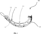
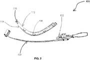
- FIG. 1 illustrates an assembled view whereas FIG. 2 illustrates an exploded view of the apparatus 100.
- various associated elements may be well-known to those skilled in the art, it is not deemed necessary for purposes of acquiring an understanding of the present disclosure that there be recited herein all of the constructional details and explanation thereof. Rather, it is deemed sufficient to simply note that as shown in FIGS. 1 and 2 , in the apparatus 100, only those components are shown that are relevant for the description of various embodiments of the present disclosure.
- the apparatus 100 includes a guide member 110, a guide adapting member 120 and scanning probes 122 in a configuration.
- the guide member 110 includes a first surface 112 and a second surface 114 distal from the first surface 112. Particularly, the first and second surfaces 112, 114 are opposite to each other.
- the first surface 112 is designed in a manner to adaptably mirror a shape of a portion of the component C to be inspected.
- the guide member 110 may be a water-cut mask made from one of rubber, plastic or metal.
- the guide member 110 may be made from any other material, such as wood, partial board, etc., by using suitable techniques.
- Such guide member 110 is configured to the guide adapting member 120.
- the guide adapting member 120 is capable of releasably attaching the guide member 110 from the second surface 114 of the guide member 110 by releasable attachments 130.
- This is one a salient feature of the apparatus 100 that the guide member 110 is adaptably changeable as per the shape of the portion of the component C, to be releasably attached over the guide adapting member 120 via the releasable attachments 130.
- releasable attachments 130 may be snap fit attachments, riveted attachments, nut-bolt attachments, and the like.
- the guide adapting member 120 may be a flexible steel rail arrangement bendable to adapt a shape of the second surface 114 of the guide member 110 to releasably attach the guide member 110 depending upon the shape of the guide member 110.
- the guide adapting member 120 may be made of any suitable material having required flexibility and bendability to adapt the shape of the second surface 114 of the guide member 110 and to releasably attach the guide member 110.
- the scanning probes 122 may be located on the guide adapting member 120 for being configured to be movable along the second surface 114 of the guide member 110 to generate and receive ultrasonic waves used to inspect the component C.
- the scanning probes 122 may be phased array scanning probes, which allow beam steer and skew, i. e. the beam can be steered in two planes. Using such phased array scanning probes, an area or portion which can be inspected from a specific position of the component C may be increased.
- phased array scanning probes may be moveably positioned along the second surface 114 on the guide member 110, between the guide member 110 and the guide adapting member 120, and may be coupled to a coupler placed proximate to the first surface 112 of the guide member 110 to transmit and receive ultrasonic waves towards and from the second surface 114 for inspection of the portion of the component C.
- the shape of the second surface 114 of the guide member 110 is adaptable to the surface shape of the portion of the component C to render positioning of the scanning probes 122 to enable the ultrasonic waves to appropriately approach the components C, if required by such coupler.
- the scanning probes 122 may be positioned such that the ultrasonic waves from the scanning probes 122 radially approach the component C to the surface of the component C.
- the apparatus 100 may include a processing unit for at least visualizing and processing the received ultrasonic waves from the scanning probes 122 for analyzing flaws, such as crakes in the component C.
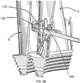
- FIGS. 3A and 3B which illustrate ultrasonic inspection of the component C, such as low pressure last stage steam turbine blades, using the apparatus 100.
- the guide member 110 as per the shape of the portion the component C is selected, and is releasably attached to the guide adapting member 120 by the releasable attachment 130 for configuring the apparatus 100 as shown in FIG. 3B to inspect the component C.
- the apparatus 100 may be placed between the turbine blades such that the second surface 114 of the guide member 110 faces that turbine blade which is to be inspected.
- the guide member 110 is designed, specifically the second surface 114 thereof, to adaptably mirror, i.e. to match the shape of the portion of the turbine blade. Since, the turbine blades are of varying profile, the apparatus 100 may be modified to adapt to any varying size, shape and geometry of the turbine blade to be inspected, by changing the guide member 110 as per the turbine blade profile or the portion of the turbine blade from the guide adapting member 120 to obtain the apparatus, such as the apparatus 100, suitable of a specific turbine blade or a portion of the turbine blade.
- the scanning probes 122 Upon matching of the profile of the guide member 110 with the turbine blade profile, the scanning probes 122, which is movable along the second surface 114 of the guide member 110 generate and receive ultrasonic waves for scanning the turbine blades.
- the apparatus 100 may be inserted between the turbine blades even in case of blades mounted inside the turbine, as specifically shown in FIG. 3B .
- the method 200 includes a selection of a guide member, such as the guide member 110, as described above, as per the shape of a portion of the component C.
- selection of the guide member may be made randomly by matching various guide members with the shape of the component C that is to be inspected, to determine a suitable guide member that mirrors the component C.
- the selection of the suitable profile of the guide member 110 as per the shape of the component C may be made by any other technique.
- the selected guide member is releasably attached to a guide adapting member by releasable attachments, such as the releasable attachments 130 as described above.
- the guide adapting member is same (guide adapting member 120) as described above, and includes scanning probes, similar to the scanning probes 122.
- the guide member, which is releasably attached to the guide adapting member is directed on the surface of the component C, and enabling the scanning probes, at 240, to generate and receive ultrasonic waves for inspection of the component C.
- the apparatus and the method for an ultrasonic inspection of the components of the present disclosure are advantageous in various scopes.
- the apparatus and method of the disclosure are adaptable in terms of being modified for ultrasonic inspection of a component, like low pressure last stage steam turbine blades of varying shapes, size and geometries.
- the guide member is changeable per the shape of the component to be releasably attached over the guide adapting member.
- the apparatus and method are convenient to use and economical.
Landscapes
- Physics & Mathematics (AREA)
- Health & Medical Sciences (AREA)
- Life Sciences & Earth Sciences (AREA)
- Chemical & Material Sciences (AREA)
- Analytical Chemistry (AREA)
- Biochemistry (AREA)
- General Health & Medical Sciences (AREA)
- General Physics & Mathematics (AREA)
- Immunology (AREA)
- Pathology (AREA)
- Investigating Or Analyzing Materials By The Use Of Ultrasonic Waves (AREA)
Description
- The present disclosure relates to a non-destructive material inspection, and, more particularly, to an apparatus and a method for ultrasonic inspection of components, including but not limited to, low pressure last stage steam turbine blades.
- Non-destructive material inspection using ultrasonic waves for the detection of flaws in components are well known conventionally.
- More often than not, challenges arrive while ultrasonic inspection of components, such as aerofoil, filet radius, and specifically, while inspection of low pressure last stage steam turbine blades due to its varying size, shapes and geometries, and compactness of the blades with respect to each other. Generally, for ultrasonic inspection for such turbine blades, conventionally known specialized tools are available those have varying shapes and designs and include probes. These conventionally know tools of varying shapes and size with the probes are inserted between the blades for inspection thereof. The probes release and receive ultrasonic waves on the blades to determine flaws in the blades. Among the various requirements for the accurate ultrasonic inspection of the blades by the conventional tool, one of the essential requirements is matching of the tool profile with the blade profile. This requirement makes it essential to produce various tools with probes with respect to each individual blade profile adding to overall cost of inspection of turbine blades.
- An example of a known tool is discussed in
U.S. patent application no. 2007/0044564 A1 . The tool comprises a sensor holder that is shaped to conform to the shape of a test body and further made of a material that enables rapid prototyping. By means of an adjustable corner portion the sensor holder's shape may be adjusted to take into accout various widths of the test body along its length. The sensor fixed to the holder may be an ultrasonic inspection device. - Another example of a known tool is discussed in
EP2096433A1 . The tool comprises a rail for guiding the carriage that is used to hold a test heading configured for nondestructively material testing. The rail is made of, for example, epoxy resin thus enabling quickly manufactured of a rail that conforms to the surface shape of a test body. The rail further includes grooves in which guiding rollers of the carriage can be inserted, that guide the carriage along the length of the rail. This enables the testing head, which is mounted on the carriage, to direct a testing device along a defined path of the test body. - Such conventional tools may be quite in practice, and may have generally been considered satisfactory for their intended purposes, but may be unsatisfactory in terms of adaptability thereof with respect to varying shapes, size and geometries of the blades.
- Accordingly, there exists a need for an ultrasonic inspection of components in an economical and adaptable manner.
- The present disclosure describes an apparatus and a method for ultrasonic inspection of a component, like low pressure last stage turbine blades, that will be presented in the following simplified summary to provide a basic understanding of one or more aspects of the disclosure that are intended to overcome the discussed drawbacks, but to include all advantages thereof, along with providing some additional advantages. This summary is not an extensive overview of the disclosure. It is intended to neither identify key or critical elements of the disclosure, nor to delineate the scope of the present disclosure. Rather, the sole purpose of this summary is to present some concepts of the disclosure, its aspects and advantages in a simplified form as a prelude to the more detailed description that is presented hereinafter.
- An object of the present disclosure is to describe an apparatus and a method, which may be adaptable in terms of being modified for ultrasonic inspection of a component, like low pressure last stage turbine blades of varying shapes, size and geometries. Another object of the present disclosure is to describe an apparatus and a method, which are convenient to use in an effective and economical way. Various other objects and features of the present disclosure will be apparent from the following detailed description and claims.
- The above noted and other objects, in one aspect, may be achieved by an apparatus for ultrasonic inspection of a component. In other aspects, above noted and other objects, may be achieved by a method for ultrasonic inspection of a component. Examples of the components, where such apparatus and method may be utilized, including but not limited to, are low pressure last stage turbine blades, aerofoil and filet radius, etc.. While the disclosure will be described in conjunction with the turbine blades for the purpose of better understanding, the scope of the disclosure will extend to all such components where the present apparatus and method may be successfully utilized.
- According to the above aspects of the present disclosure, a component inspection apparatus for ultrasonic inspection of a component according to claim 1 is disclosed. The apparatus includes a guide member, a guide adapting member and scanning probes. The guide member has a first surface and a distal second surface. The first surface is configured to adaptably mirror a shape of a portion of the component, such that the
guide member 110 is adaptably changeable to the shape of a portion of the component. The guide adapting member is capable of releasably attaching to the second surface of the guide member. The scanning probes are located on the guide adapting member in a manner configured to be movable along the second surface of the guide member to generate and receive ultrasonic waves used to inspect the component. - The apparatus may further include a processing unit, which may be utilized to at least visualise and process the ultrasonic waves received by the scanning probes.
- In one embodiment of the present disclosure, the guide adapting member may be a flexible steel rail arrangement bendably and releasably attachable to the guide member depending upon the shape thereof. In one embodiment, the guide member may be a water-cut mask made from one of a rubber, plastic, wood or metal. In one embodiment, a shape of the second surface of the guide member may be adaptable to a surface shape of a portion of the component to render positioning of the scanning probes to enable the ultrasonic waves to appropriately approach the component. In one form, the scanning probes are positioned such that the ultrasonic waves from the scanning probes approach the component radially to the surface of the component.
- In another aspect of the present disclosure, a method for ultrasonic inspection of a component according to claim 7 is disclosed. The method includes selecting a guide member as per a shape of a portion of the component to be inspected. The guide member is same as summarized above. The selected guide member from its second surface is releasably attached to a guide adapting member. The guide adapting member is same as summarized above, and includes scanning probes, similar to summarized above. Thereafter, the guide member, releasably attached to the guide adapting member, is directed onto a surface of the component, whereat the scanning probes generate and receive ultrasonic waves based on the shape of the component.
- The method may further include at least visualizing and processing of the received ultrasonic waves from the scanning probes.
- In one embodiment, generating and receiving ultrasonic waves include adapting a shape of the second surface the guide member to a surface shape of a portion of the component to render positioning of the scanning probes to enable the ultrasonic waves to appropriately approach the component. In one form, the ultrasonic waves from the scanning probes may radially approach the component to the surface of the component.
- These together with the other aspects of the present disclosure, along with the various features of novelty that characterize the present disclosure, are pointed out with particularity in the present disclosure. For a better understanding of the present disclosure, its operating advantages, and its uses, reference should be made to the accompanying drawings and descriptive matter in which there are illustrated exemplary embodiments of the present disclosure.
- The advantages and features of the present disclosure will be better understood with reference to the following detailed description and claims taken in conjunction with the accompanying drawing, wherein like elements are identified with like symbols, and in which:
-
FIG. 1 illustrates an example of an apparatus for ultrasonic inspection of components, in accordance with an exemplary embodiment of the present disclosure; -
FIG. 2 illustrates an exploded view of the apparatus ofFIG. 1 , in accordance with an exemplary embodiment of the present disclosure; -
FIGS. 3A and3B illustrate utilization of the apparatus ofFIG. 1 with a component, such as, low pressure last stage turbine blades, in accordance with an exemplary embodiment of the present disclosure; and -
FIG. 4 illustrates a flow diagram depicting a method for ultrasonic inspection utilizing the apparatus ofFIG. 1 , in accordance with an exemplary embodiment of the present disclosure. - Like reference numerals refer to like parts throughout the description of several views of the drawings.
- For a thorough understanding of the present disclosure, reference is to be made to the following detailed description, including the appended claims, in connection with the above described drawings. In the following description, for purposes of explanation, numerous specific details are set forth in order to provide a thorough understanding of the present disclosure. It will be apparent, however, to one skilled in the art that the present disclosure can be practiced without these specific details. In other instances, structures and apparatuses are shown in block diagrams form only, in order to avoid obscuring the disclosure. Reference in this specification to "one embodiment," "an embodiment," "another embodiment," "various embodiments," means that a particular feature, structure, or characteristic described in connection with the embodiment is included in at least one embodiment of the present disclosure. The appearance of the phrase "in one embodiment" in various places in the specification are not necessarily all referring to the same embodiment, nor are separate or alternative embodiments mutually exclusive of other embodiments. Moreover, various features are described which may be exhibited by some embodiments and not by others. Similarly, various requirements are described which may be requirements for some embodiments but may not be of other embodiment's requirement.
- Although the following description contains many specifics for the purposes of illustration, anyone skilled in the art will appreciate that many variations and/or alterations to these details are within the scope of the present disclosure. Similarly, although many of the features of the present disclosure are described in terms of each other, or in conjunction with each other, one skilled in the art will appreciate that many of these features can be provided independently of other features. Accordingly, this description of the present disclosure is set forth without any loss of generality to, and without imposing limitations upon, the present disclosure. Further, the relative terms, such as "first," "second," and the like, herein do not denote any order, elevation or importance, but rather are used to distinguish one element from another. Further, the terms "a" and "an" herein do not denote a limitation of quantity, but rather denote the presence of at least one of the referenced item.
- Referring now to
FIGS. 1 and2 , examples of a component inspection apparatus 100 (hereinafter 'apparatus 100') for an ultrasonic inspection of a component 'C,' (shown inFIGS. 3A and3B ), are illustrated in accordance with an exemplary embodiment of the present disclosure.FIG. 1 illustrates an assembled view whereasFIG. 2 illustrates an exploded view of theapparatus 100. In as much as the construction and arrangement of theapparatus 100, various associated elements may be well-known to those skilled in the art, it is not deemed necessary for purposes of acquiring an understanding of the present disclosure that there be recited herein all of the constructional details and explanation thereof. Rather, it is deemed sufficient to simply note that as shown inFIGS. 1 and2 , in theapparatus 100, only those components are shown that are relevant for the description of various embodiments of the present disclosure. - The
apparatus 100 includes aguide member 110, aguide adapting member 120 andscanning probes 122 in a configuration. Theguide member 110 includes afirst surface 112 and asecond surface 114 distal from thefirst surface 112. Particularly, the first andsecond surfaces first surface 112 is designed in a manner to adaptably mirror a shape of a portion of the component C to be inspected. In one embodiment, theguide member 110 may be a water-cut mask made from one of rubber, plastic or metal. However, without departing from the scope of the present disclosure, theguide member 110 may be made from any other material, such as wood, partial board, etc., by using suitable techniques.Such guide member 110 is configured to theguide adapting member 120. Specifically, theguide adapting member 120 is capable of releasably attaching theguide member 110 from thesecond surface 114 of theguide member 110 byreleasable attachments 130. This is one a salient feature of theapparatus 100 that theguide member 110 is adaptably changeable as per the shape of the portion of the component C, to be releasably attached over theguide adapting member 120 via thereleasable attachments 130. Examples of suchreleasable attachments 130 may be snap fit attachments, riveted attachments, nut-bolt attachments, and the like. - In one embodiment of the present disclosure, the
guide adapting member 120 may be a flexible steel rail arrangement bendable to adapt a shape of thesecond surface 114 of theguide member 110 to releasably attach theguide member 110 depending upon the shape of theguide member 110. However, without departing from the scope of the present disclosure, theguide adapting member 120 may be made of any suitable material having required flexibility and bendability to adapt the shape of thesecond surface 114 of theguide member 110 and to releasably attach theguide member 110. - The scanning probes 122 may be located on the
guide adapting member 120 for being configured to be movable along thesecond surface 114 of theguide member 110 to generate and receive ultrasonic waves used to inspect the component C. In one embodiment of the present disclosure, the scanning probes 122 may be phased array scanning probes, which allow beam steer and skew, i. e. the beam can be steered in two planes. Using such phased array scanning probes, an area or portion which can be inspected from a specific position of the component C may be increased. - In an example, such phased array scanning probes may be moveably positioned along the
second surface 114 on theguide member 110, between theguide member 110 and theguide adapting member 120, and may be coupled to a coupler placed proximate to thefirst surface 112 of theguide member 110 to transmit and receive ultrasonic waves towards and from thesecond surface 114 for inspection of the portion of the component C. The shape of thesecond surface 114 of theguide member 110 is adaptable to the surface shape of the portion of the component C to render positioning of the scanning probes 122 to enable the ultrasonic waves to appropriately approach the components C, if required by such coupler. In an example, the scanning probes 122 may be positioned such that the ultrasonic waves from the scanning probes 122 radially approach the component C to the surface of the component C. - The
apparatus 100 may include a processing unit for at least visualizing and processing the received ultrasonic waves from the scanning probes 122 for analyzing flaws, such as crakes in the component C. - Referring now to
FIGS. 3A and3B , which illustrate ultrasonic inspection of the component C, such as low pressure last stage steam turbine blades, using theapparatus 100. InFIG. 3A , theguide member 110 as per the shape of the portion the component C is selected, and is releasably attached to theguide adapting member 120 by thereleasable attachment 130 for configuring theapparatus 100 as shown inFIG. 3B to inspect the component C. - The
apparatus 100 may be placed between the turbine blades such that thesecond surface 114 of theguide member 110 faces that turbine blade which is to be inspected. Theguide member 110 is designed, specifically thesecond surface 114 thereof, to adaptably mirror, i.e. to match the shape of the portion of the turbine blade. Since, the turbine blades are of varying profile, theapparatus 100 may be modified to adapt to any varying size, shape and geometry of the turbine blade to be inspected, by changing theguide member 110 as per the turbine blade profile or the portion of the turbine blade from theguide adapting member 120 to obtain the apparatus, such as theapparatus 100, suitable of a specific turbine blade or a portion of the turbine blade. Upon matching of the profile of theguide member 110 with the turbine blade profile, the scanning probes 122, which is movable along thesecond surface 114 of theguide member 110 generate and receive ultrasonic waves for scanning the turbine blades. Theapparatus 100 may be inserted between the turbine blades even in case of blades mounted inside the turbine, as specifically shown inFIG. 3B . - Referring now to
FIG. 4 , a flow diagram of amethod 200 for an ultrasonic inspection of a component C, like low pressure last stage steam turbine blades, is illustrated, in accordance with exemplary embodiment of the present disclosure. Themethod 200, at 210, includes a selection of a guide member, such as theguide member 110, as described above, as per the shape of a portion of the component C. In one embodiment of the present disclosure, selection of the guide member may be made randomly by matching various guide members with the shape of the component C that is to be inspected, to determine a suitable guide member that mirrors the component C. However, without departing from the scope of the present disclosure, the selection of the suitable profile of theguide member 110 as per the shape of the component C may be made by any other technique. - Further, at 220, the selected guide member is releasably attached to a guide adapting member by releasable attachments, such as the
releasable attachments 130 as described above. The guide adapting member is same (guide adapting member 120) as described above, and includes scanning probes, similar to the scanning probes 122. Thereafter at 230, the guide member, which is releasably attached to the guide adapting member, is directed on the surface of the component C, and enabling the scanning probes, at 240, to generate and receive ultrasonic waves for inspection of the component C. - The apparatus and the method for an ultrasonic inspection of the components of the present disclosure are advantageous in various scopes. The apparatus and method of the disclosure are adaptable in terms of being modified for ultrasonic inspection of a component, like low pressure last stage steam turbine blades of varying shapes, size and geometries. Specifically, the guide member is changeable per the shape of the component to be releasably attached over the guide adapting member. Further, the apparatus and method are convenient to use and economical. Various other advantages and features of the present disclosure are apparent from the above detailed description and appendage claims.
-
- 100
- Apparatus for ultrasonic inspection
- 110
- Guide member
- 112
- First surface
- 114
- Second surface
- 120
- Guide adapting member
- 122
- Scanning probes
- 130
- Releasable attachment
- 200
- Method
- 210-240
- Method steps
- C
- Component
Claims (11)
- A component inspection apparatus 100 for ultrasonic inspection of a component C, including low pressure last stage steam turbine blades, the apparatus 100 comprising:a guide member 110 having a first surface 112 and a second surface 114 distal from the first surface 112, wherein the first surface 112 is configured to mirror a shape of a portion of the component C, such that the guide member 110 is adaptably changeable to the shape of the portion of the component C and the second surface 114 has a length between distal ends;a guide adapting member 120 configured to be releasably attachable to the second surface 114 of the guide member 110; andscanning probes 122 located on the guide adapting member 120 in a manner configured to be movable along the second surface 114 of the guide member 110 to generate and receive ultrasonic waves used to inspect the component C,characterised by the guiding adapting member 120 being configured to be adoptable to a shape of the second surface 114 and to be releasably attachable to the second surface 114 of the guide member 110 over the length of the second surface 114.
- The apparatus 100 as claimed in claim 1 further comprising a processing unit configured and arranged to at least visualise and process the ultrasonic waves received by the scanning probes 122.
- The apparatus 100 as claimed in claim 1, wherein the guide adapting member 120 is a flexible steel rail arrangement bendable to adopt a shape of the second surface 114 of the guide member 110 to releasably attach the guide member 110.
- The apparatus 100 as claimed in claim 1, wherein a shape of the second surface 114 of the guide member 110 is adaptable to a surface shape of a portion of the component C to render positioning of the scanning probes 122 to enable the ultrasonic waves to appropriately approach the components C.
- The apparatus 100 as claimed in claim 4, wherein the scanning probes 122 are positioned such that the ultrasonic waves from the scanning probes 122 radially approach to the portion of the component C.
- The apparatus 100 as claimed in claim 1, wherein the guide member 110 is a water-cut mask made from one of a selection of rubber, plastic, or metal.
- A method 200 for ultrasonic inspection of a component C, including low pressure last stage steam turbine blades, the method 200 comprising:selecting a guide member 110 as per a shape of a portion of the component C to be inspected, the guide member 110 having a first surface 112 and a distal second surface 114, wherein the first surface 112 is configured to mirror the shape of the portion of the component C and the second surface 114 has a length between distal ends; adopting a guide adapting member 120 to a shape of the second surface 114 and releasably attaching the guide adapting member 120 to the guide member 110 over the length of the second surface 114 of the guide member 110;directing the guide member 110, that is releasably attached to the guide adapting member 120, onto a surface of the component C; andgenerating and receiving ultrasonic waves by scanning probes 122, located on the guide adapting member 120 in a manner configured to be movable along the second surface 114 of the guide member 110, based on the component C.
- The method 200 as claimed in claim 7 further comprising at least visualizing and processing of the received ultrasonic waves from the scanning probes 122.
- The method 200 as claimed in claim 7, wherein the guide adapting member 120 is releasably, flexibly and bendably attached to the second surface 114 of the guide member 110.
- The method 200 as claimed in claim 7, wherein generating and receiving ultrasonic waves comprises adapting a shape of the second surface 114 of the guide member 110 to a surface shape of a portion of the component C to render positioning of the scanning probes 122 to enable the ultrasonic waves to appropriately approach the component C.
- The method 200 as claimed in claim 10, including arranging the scanning probes 122 such that ultrasonic waves from the scanning probes 122 radially approach the surface of the component C.
Priority Applications (5)
| Application Number | Priority Date | Filing Date | Title |
|---|---|---|---|
| EP13165902.1A EP2799861B1 (en) | 2013-04-30 | 2013-04-30 | Ultrasonic component inspection apparatus and method with a conformable guide member |
| CA2849139A CA2849139C (en) | 2013-04-30 | 2014-04-16 | Component inspection apparatus and method |
| IN1106DE2014 IN2014DE01106A (en) | 2013-04-30 | 2014-04-23 | |
| US14/262,883 US9964522B2 (en) | 2013-04-30 | 2014-04-28 | Component inspection apparatus and method |
| CN201410183957.4A CN104132994B (en) | 2013-04-30 | 2014-04-30 | Component checks device and method |
Applications Claiming Priority (1)
| Application Number | Priority Date | Filing Date | Title |
|---|---|---|---|
| EP13165902.1A EP2799861B1 (en) | 2013-04-30 | 2013-04-30 | Ultrasonic component inspection apparatus and method with a conformable guide member |
Publications (2)
| Publication Number | Publication Date |
|---|---|
| EP2799861A1 EP2799861A1 (en) | 2014-11-05 |
| EP2799861B1 true EP2799861B1 (en) | 2018-01-10 |
Family
ID=48236697
Family Applications (1)
| Application Number | Title | Priority Date | Filing Date |
|---|---|---|---|
| EP13165902.1A Active EP2799861B1 (en) | 2013-04-30 | 2013-04-30 | Ultrasonic component inspection apparatus and method with a conformable guide member |
Country Status (5)
| Country | Link |
|---|---|
| US (1) | US9964522B2 (en) |
| EP (1) | EP2799861B1 (en) |
| CN (1) | CN104132994B (en) |
| CA (1) | CA2849139C (en) |
| IN (1) | IN2014DE01106A (en) |
Families Citing this family (3)
| Publication number | Priority date | Publication date | Assignee | Title |
|---|---|---|---|---|
| CN105806942B (en) * | 2014-12-30 | 2018-09-28 | 中核武汉核电运行技术股份有限公司 | A kind of root of blade ultrasound automatic checking device |
| US9625286B2 (en) * | 2015-01-09 | 2017-04-18 | Olympus Scientific Solutions Americas Inc. | Adjustable probe holder assembly for an inspection sensor |
| EP3290894B1 (en) * | 2016-09-06 | 2022-12-07 | General Electric Technology GmbH | Inspection probe |
Family Cites Families (8)
| Publication number | Priority date | Publication date | Assignee | Title |
|---|---|---|---|---|
| US6772635B1 (en) * | 2002-03-06 | 2004-08-10 | The United States Of America As Represented By The United States Department Of Energy | Method and apparatus for remote delivery and manipulation of a miniature tool adjacent a work piece in a restricted space |
| CN2687667Y (en) | 2003-03-14 | 2005-03-23 | 中国科学院声学研究所 | Wheel type scanning probe capable of directly generating pure trans versal wave |
| US7174788B2 (en) * | 2003-12-15 | 2007-02-13 | General Electric Company | Methods and apparatus for rotary machinery inspection |
| US7617732B2 (en) * | 2005-08-26 | 2009-11-17 | The Boeing Company | Integrated curved linear ultrasonic transducer inspection apparatus, systems, and methods |
| CN2932390Y (en) | 2006-07-24 | 2007-08-08 | 枣庄供电公司 | Probe scanning mechanism |
| FR2921499B1 (en) | 2007-09-26 | 2009-11-13 | Snecma | CATHETER OR ENDOSCOPE-TYPE ORIENTABLE STRUCTURE |
| EP2096433A1 (en) * | 2008-02-26 | 2009-09-02 | Siemens Aktiengesellschaft | Device for non-destructive materials testing of a test specimen with ultrasonic waves |
| EP2447714A1 (en) * | 2010-10-28 | 2012-05-02 | Siemens Aktiengesellschaft | Automatic probe position-dependent angle of incidence adjustment for ultrasound probes |
-
2013
- 2013-04-30 EP EP13165902.1A patent/EP2799861B1/en active Active
-
2014
- 2014-04-16 CA CA2849139A patent/CA2849139C/en not_active Expired - Fee Related
- 2014-04-23 IN IN1106DE2014 patent/IN2014DE01106A/en unknown
- 2014-04-28 US US14/262,883 patent/US9964522B2/en active Active
- 2014-04-30 CN CN201410183957.4A patent/CN104132994B/en not_active Expired - Fee Related
Non-Patent Citations (1)
| Title |
|---|
| None * |
Also Published As
| Publication number | Publication date |
|---|---|
| CA2849139C (en) | 2016-06-07 |
| CN104132994A (en) | 2014-11-05 |
| US20140318257A1 (en) | 2014-10-30 |
| CN104132994B (en) | 2017-01-04 |
| EP2799861A1 (en) | 2014-11-05 |
| IN2014DE01106A (en) | 2015-06-05 |
| CA2849139A1 (en) | 2014-10-30 |
| US9964522B2 (en) | 2018-05-08 |
Similar Documents
| Publication | Publication Date | Title |
|---|---|---|
| US8347746B2 (en) | Crawling automated scanner for non-destructive inspection of aerospace structural elements | |
| Khaji et al. | Closed-form solutions for crack detection problem of Timoshenko beams with various boundary conditions | |
| US9964522B2 (en) | Component inspection apparatus and method | |
| EP2341324A3 (en) | Systems and methods for measuring turbine blade vibratory response | |
| US9255858B2 (en) | Method for measuring fiber cutting force | |
| US10422620B2 (en) | Contact-type position measuring device and measuring method using the same | |
| CN101393169A (en) | Device for inspecting the tangential recesses of a rotor disc | |
| EP2883046B1 (en) | Improvements to radius inspection tools | |
| US9518851B2 (en) | Probes for inspection system for substantially round hole | |
| WO2015148691A3 (en) | Ultrasonic diagnostic device and system | |
| US20190162531A1 (en) | Measurement system, machining system, measurement method, and computer-readable recording medium | |
| US10161914B2 (en) | Inspection methods with probe for substantially round hole | |
| DE502005000480D1 (en) | Method and device for determining the deflection of a connecting element | |
| EP4235091A3 (en) | Surface finish stylus | |
| Prata Jr et al. | Wind friction parametrisation used in emission models for wastewater treatment plants: A critical review | |
| CN103201622A (en) | Automatic incidence angle adjustment for ultrasound test heads which is dependent on the position of the test heads | |
| WO2010004167A3 (en) | Method and machine for multidimensional testing of an electronic device on the basis of a monodirectional probe | |
| CN106932491A (en) | Channel ultrasonic detects scanning frame | |
| CN213398345U (en) | Gas turbine compressor impeller blade root groove normal position ultrasonic detection frock | |
| US20200030892A1 (en) | Method, system, computer program and a computer program product for working of a workpiece | |
| US9116097B2 (en) | Part fixture for nondestructive inspection | |
| JP6489901B2 (en) | Ultrasonic inspection equipment | |
| CN103196999B (en) | For operating instrument and the method for sensor cluster | |
| Schwabe et al. | Ultrasonic testing machines with robot mechanics–a new approach to CFRP component testing | |
| CN113664823A (en) | Method for performing multiple operations in an area of a part using an end effector of a robot and a robot for performing the method |
Legal Events
| Date | Code | Title | Description |
|---|---|---|---|
| PUAI | Public reference made under article 153(3) epc to a published international application that has entered the european phase |
Free format text: ORIGINAL CODE: 0009012 |
|
| 17P | Request for examination filed |
Effective date: 20140402 |
|
| AK | Designated contracting states |
Kind code of ref document: A1 Designated state(s): AL AT BE BG CH CY CZ DE DK EE ES FI FR GB GR HR HU IE IS IT LI LT LU LV MC MK MT NL NO PL PT RO RS SE SI SK SM TR |
|
| AX | Request for extension of the european patent |
Extension state: BA ME |
|
| RAP1 | Party data changed (applicant data changed or rights of an application transferred) |
Owner name: GENERAL ELECTRIC TECHNOLOGY GMBH |
|
| RIC1 | Information provided on ipc code assigned before grant |
Ipc: G01N 29/22 20060101AFI20170712BHEP Ipc: G01N 29/26 20060101ALI20170712BHEP Ipc: G01N 29/265 20060101ALI20170712BHEP |
|
| GRAP | Despatch of communication of intention to grant a patent |
Free format text: ORIGINAL CODE: EPIDOSNIGR1 |
|
| INTG | Intention to grant announced |
Effective date: 20170906 |
|
| GRAS | Grant fee paid |
Free format text: ORIGINAL CODE: EPIDOSNIGR3 |
|
| GRAA | (expected) grant |
Free format text: ORIGINAL CODE: 0009210 |
|
| AK | Designated contracting states |
Kind code of ref document: B1 Designated state(s): AL AT BE BG CH CY CZ DE DK EE ES FI FR GB GR HR HU IE IS IT LI LT LU LV MC MK MT NL NO PL PT RO RS SE SI SK SM TR |
|
| REG | Reference to a national code |
Ref country code: CH Ref legal event code: EP Ref country code: AT Ref legal event code: REF Ref document number: 962957 Country of ref document: AT Kind code of ref document: T Effective date: 20180115 |
|
| REG | Reference to a national code |
Ref country code: IE Ref legal event code: FG4D |
|
| REG | Reference to a national code |
Ref country code: DE Ref legal event code: R096 Ref document number: 602013032031 Country of ref document: DE |
|
| REG | Reference to a national code |
Ref country code: NL Ref legal event code: MP Effective date: 20180110 |
|
| REG | Reference to a national code |
Ref country code: AT Ref legal event code: MK05 Ref document number: 962957 Country of ref document: AT Kind code of ref document: T Effective date: 20180110 |
|
| PG25 | Lapsed in a contracting state [announced via postgrant information from national office to epo] |
Ref country code: NL Free format text: LAPSE BECAUSE OF FAILURE TO SUBMIT A TRANSLATION OF THE DESCRIPTION OR TO PAY THE FEE WITHIN THE PRESCRIBED TIME-LIMIT Effective date: 20180110 |
|
| PG25 | Lapsed in a contracting state [announced via postgrant information from national office to epo] |
Ref country code: NO Free format text: LAPSE BECAUSE OF FAILURE TO SUBMIT A TRANSLATION OF THE DESCRIPTION OR TO PAY THE FEE WITHIN THE PRESCRIBED TIME-LIMIT Effective date: 20180410 Ref country code: HR Free format text: LAPSE BECAUSE OF FAILURE TO SUBMIT A TRANSLATION OF THE DESCRIPTION OR TO PAY THE FEE WITHIN THE PRESCRIBED TIME-LIMIT Effective date: 20180110 Ref country code: CY Free format text: LAPSE BECAUSE OF FAILURE TO SUBMIT A TRANSLATION OF THE DESCRIPTION OR TO PAY THE FEE WITHIN THE PRESCRIBED TIME-LIMIT Effective date: 20180110 Ref country code: FI Free format text: LAPSE BECAUSE OF FAILURE TO SUBMIT A TRANSLATION OF THE DESCRIPTION OR TO PAY THE FEE WITHIN THE PRESCRIBED TIME-LIMIT Effective date: 20180110 Ref country code: LT Free format text: LAPSE BECAUSE OF FAILURE TO SUBMIT A TRANSLATION OF THE DESCRIPTION OR TO PAY THE FEE WITHIN THE PRESCRIBED TIME-LIMIT Effective date: 20180110 Ref country code: ES Free format text: LAPSE BECAUSE OF FAILURE TO SUBMIT A TRANSLATION OF THE DESCRIPTION OR TO PAY THE FEE WITHIN THE PRESCRIBED TIME-LIMIT Effective date: 20180110 |
|
| PG25 | Lapsed in a contracting state [announced via postgrant information from national office to epo] |
Ref country code: PL Free format text: LAPSE BECAUSE OF FAILURE TO SUBMIT A TRANSLATION OF THE DESCRIPTION OR TO PAY THE FEE WITHIN THE PRESCRIBED TIME-LIMIT Effective date: 20180110 Ref country code: SE Free format text: LAPSE BECAUSE OF FAILURE TO SUBMIT A TRANSLATION OF THE DESCRIPTION OR TO PAY THE FEE WITHIN THE PRESCRIBED TIME-LIMIT Effective date: 20180110 Ref country code: AT Free format text: LAPSE BECAUSE OF FAILURE TO SUBMIT A TRANSLATION OF THE DESCRIPTION OR TO PAY THE FEE WITHIN THE PRESCRIBED TIME-LIMIT Effective date: 20180110 Ref country code: LV Free format text: LAPSE BECAUSE OF FAILURE TO SUBMIT A TRANSLATION OF THE DESCRIPTION OR TO PAY THE FEE WITHIN THE PRESCRIBED TIME-LIMIT Effective date: 20180110 Ref country code: GR Free format text: LAPSE BECAUSE OF FAILURE TO SUBMIT A TRANSLATION OF THE DESCRIPTION OR TO PAY THE FEE WITHIN THE PRESCRIBED TIME-LIMIT Effective date: 20180411 Ref country code: BG Free format text: LAPSE BECAUSE OF FAILURE TO SUBMIT A TRANSLATION OF THE DESCRIPTION OR TO PAY THE FEE WITHIN THE PRESCRIBED TIME-LIMIT Effective date: 20180410 Ref country code: RS Free format text: LAPSE BECAUSE OF FAILURE TO SUBMIT A TRANSLATION OF THE DESCRIPTION OR TO PAY THE FEE WITHIN THE PRESCRIBED TIME-LIMIT Effective date: 20180110 Ref country code: IS Free format text: LAPSE BECAUSE OF FAILURE TO SUBMIT A TRANSLATION OF THE DESCRIPTION OR TO PAY THE FEE WITHIN THE PRESCRIBED TIME-LIMIT Effective date: 20180510 |
|
| REG | Reference to a national code |
Ref country code: DE Ref legal event code: R097 Ref document number: 602013032031 Country of ref document: DE |
|
| PG25 | Lapsed in a contracting state [announced via postgrant information from national office to epo] |
Ref country code: EE Free format text: LAPSE BECAUSE OF FAILURE TO SUBMIT A TRANSLATION OF THE DESCRIPTION OR TO PAY THE FEE WITHIN THE PRESCRIBED TIME-LIMIT Effective date: 20180110 Ref country code: RO Free format text: LAPSE BECAUSE OF FAILURE TO SUBMIT A TRANSLATION OF THE DESCRIPTION OR TO PAY THE FEE WITHIN THE PRESCRIBED TIME-LIMIT Effective date: 20180110 Ref country code: IT Free format text: LAPSE BECAUSE OF FAILURE TO SUBMIT A TRANSLATION OF THE DESCRIPTION OR TO PAY THE FEE WITHIN THE PRESCRIBED TIME-LIMIT Effective date: 20180110 Ref country code: AL Free format text: LAPSE BECAUSE OF FAILURE TO SUBMIT A TRANSLATION OF THE DESCRIPTION OR TO PAY THE FEE WITHIN THE PRESCRIBED TIME-LIMIT Effective date: 20180110 |
|
| PGFP | Annual fee paid to national office [announced via postgrant information from national office to epo] |
Ref country code: GB Payment date: 20180427 Year of fee payment: 6 |
|
| PLBE | No opposition filed within time limit |
Free format text: ORIGINAL CODE: 0009261 |
|
| STAA | Information on the status of an ep patent application or granted ep patent |
Free format text: STATUS: NO OPPOSITION FILED WITHIN TIME LIMIT |
|
| PG25 | Lapsed in a contracting state [announced via postgrant information from national office to epo] |
Ref country code: CZ Free format text: LAPSE BECAUSE OF FAILURE TO SUBMIT A TRANSLATION OF THE DESCRIPTION OR TO PAY THE FEE WITHIN THE PRESCRIBED TIME-LIMIT Effective date: 20180110 Ref country code: SK Free format text: LAPSE BECAUSE OF FAILURE TO SUBMIT A TRANSLATION OF THE DESCRIPTION OR TO PAY THE FEE WITHIN THE PRESCRIBED TIME-LIMIT Effective date: 20180110 Ref country code: MC Free format text: LAPSE BECAUSE OF FAILURE TO SUBMIT A TRANSLATION OF THE DESCRIPTION OR TO PAY THE FEE WITHIN THE PRESCRIBED TIME-LIMIT Effective date: 20180110 Ref country code: DK Free format text: LAPSE BECAUSE OF FAILURE TO SUBMIT A TRANSLATION OF THE DESCRIPTION OR TO PAY THE FEE WITHIN THE PRESCRIBED TIME-LIMIT Effective date: 20180110 Ref country code: SM Free format text: LAPSE BECAUSE OF FAILURE TO SUBMIT A TRANSLATION OF THE DESCRIPTION OR TO PAY THE FEE WITHIN THE PRESCRIBED TIME-LIMIT Effective date: 20180110 |
|
| REG | Reference to a national code |
Ref country code: CH Ref legal event code: PL |
|
| 26N | No opposition filed |
Effective date: 20181011 |
|
| REG | Reference to a national code |
Ref country code: BE Ref legal event code: MM Effective date: 20180430 |
|
| REG | Reference to a national code |
Ref country code: IE Ref legal event code: MM4A |
|
| PG25 | Lapsed in a contracting state [announced via postgrant information from national office to epo] |
Ref country code: LU Free format text: LAPSE BECAUSE OF NON-PAYMENT OF DUE FEES Effective date: 20180430 |
|
| PG25 | Lapsed in a contracting state [announced via postgrant information from national office to epo] |
Ref country code: BE Free format text: LAPSE BECAUSE OF NON-PAYMENT OF DUE FEES Effective date: 20180430 Ref country code: SI Free format text: LAPSE BECAUSE OF FAILURE TO SUBMIT A TRANSLATION OF THE DESCRIPTION OR TO PAY THE FEE WITHIN THE PRESCRIBED TIME-LIMIT Effective date: 20180110 Ref country code: CH Free format text: LAPSE BECAUSE OF NON-PAYMENT OF DUE FEES Effective date: 20180430 Ref country code: LI Free format text: LAPSE BECAUSE OF NON-PAYMENT OF DUE FEES Effective date: 20180430 |
|
| PG25 | Lapsed in a contracting state [announced via postgrant information from national office to epo] |
Ref country code: IE Free format text: LAPSE BECAUSE OF NON-PAYMENT OF DUE FEES Effective date: 20180430 Ref country code: FR Free format text: LAPSE BECAUSE OF NON-PAYMENT OF DUE FEES Effective date: 20180430 |
|
| GBPC | Gb: european patent ceased through non-payment of renewal fee |
Effective date: 20190430 |
|
| PG25 | Lapsed in a contracting state [announced via postgrant information from national office to epo] |
Ref country code: GB Free format text: LAPSE BECAUSE OF NON-PAYMENT OF DUE FEES Effective date: 20190430 Ref country code: MT Free format text: LAPSE BECAUSE OF NON-PAYMENT OF DUE FEES Effective date: 20180430 |
|
| PG25 | Lapsed in a contracting state [announced via postgrant information from national office to epo] |
Ref country code: TR Free format text: LAPSE BECAUSE OF FAILURE TO SUBMIT A TRANSLATION OF THE DESCRIPTION OR TO PAY THE FEE WITHIN THE PRESCRIBED TIME-LIMIT Effective date: 20180110 |
|
| PG25 | Lapsed in a contracting state [announced via postgrant information from national office to epo] |
Ref country code: HU Free format text: LAPSE BECAUSE OF FAILURE TO SUBMIT A TRANSLATION OF THE DESCRIPTION OR TO PAY THE FEE WITHIN THE PRESCRIBED TIME-LIMIT; INVALID AB INITIO Effective date: 20130430 Ref country code: PT Free format text: LAPSE BECAUSE OF FAILURE TO SUBMIT A TRANSLATION OF THE DESCRIPTION OR TO PAY THE FEE WITHIN THE PRESCRIBED TIME-LIMIT Effective date: 20180110 |
|
| PG25 | Lapsed in a contracting state [announced via postgrant information from national office to epo] |
Ref country code: MK Free format text: LAPSE BECAUSE OF NON-PAYMENT OF DUE FEES Effective date: 20180110 |
|
| PGFP | Annual fee paid to national office [announced via postgrant information from national office to epo] |
Ref country code: DE Payment date: 20250319 Year of fee payment: 13 |