EP2799839A1 - Machine provided with lubricating oil deterioration sensor and industrial robot - Google Patents
Machine provided with lubricating oil deterioration sensor and industrial robot Download PDFInfo
- Publication number
- EP2799839A1 EP2799839A1 EP12862888.0A EP12862888A EP2799839A1 EP 2799839 A1 EP2799839 A1 EP 2799839A1 EP 12862888 A EP12862888 A EP 12862888A EP 2799839 A1 EP2799839 A1 EP 2799839A1
- Authority
- EP
- European Patent Office
- Prior art keywords
- lubricant
- gap
- light
- sensor
- deterioration
- Prior art date
- Legal status (The legal status is an assumption and is not a legal conclusion. Google has not performed a legal analysis and makes no representation as to the accuracy of the status listed.)
- Withdrawn
Links
Images





Classifications
-
- G—PHYSICS
- G01—MEASURING; TESTING
- G01N—INVESTIGATING OR ANALYSING MATERIALS BY DETERMINING THEIR CHEMICAL OR PHYSICAL PROPERTIES
- G01N21/00—Investigating or analysing materials by the use of optical means, i.e. using sub-millimetre waves, infrared, visible or ultraviolet light
- G01N21/17—Systems in which incident light is modified in accordance with the properties of the material investigated
- G01N21/25—Colour; Spectral properties, i.e. comparison of effect of material on the light at two or more different wavelengths or wavelength bands
- G01N21/31—Investigating relative effect of material at wavelengths characteristic of specific elements or molecules, e.g. atomic absorption spectrometry
-
- G—PHYSICS
- G01—MEASURING; TESTING
- G01N—INVESTIGATING OR ANALYSING MATERIALS BY DETERMINING THEIR CHEMICAL OR PHYSICAL PROPERTIES
- G01N21/00—Investigating or analysing materials by the use of optical means, i.e. using sub-millimetre waves, infrared, visible or ultraviolet light
- G01N21/84—Systems specially adapted for particular applications
- G01N21/85—Investigating moving fluids or granular solids
- G01N21/8507—Probe photometers, i.e. with optical measuring part dipped into fluid sample
Definitions
- the present invention relates to a machine provided with a lubricant deterioration sensor for detecting the deterioration of lubricant.
- an oil deterioration degree sensor for detecting the deterioration of lubricant of a machine.
- an oil entering gap portion for entering lubricant therein is formed on an optical path from an infrared LED (Light Emitting Diode) to a photo diode. Then, an amount of light absorption by the lubricant within the oil entering gap portion with respect to light emitted from the infrared LED is measured according to a light reception amount of the photo diode, to thereby determine a deterioration degree of the lubricant related to the light absorption amount thus measured (see patent literatures 1 and 2, for example).
- the oil deterioration degree sensor described in each of the patent literatures 1 and 2 has a problem that, although a density of insoluble content within the lubricant can be measured as the deterioration degree of the lubricant, kinds of contaminant within the lubricant can not be specified.
- Mo organic molybdenum
- MoDTC molybdenum dithiocarbamate
- MoDTP molybdenum dithiophosphate
- an object of this invention is to provide a machine which can suppress the degradation of performance of a lubricant deterioration sensor that can immediately specify the kinds and amounts of contaminant within lubricant.
- a machine which is configured to detect deterioration of lubricant, including:
- the lubricant deterioration sensor may further includes a supporting member which supports the light emitting element, the color light reception element and the gap forming member, and a fixing member to be fixed to the machine body.
- the fixing member may support the supporting member so as to be rotatable so that a direction of an opening of the oil gap changes when the supporting member rotates.
- the supporting member may be provided with a rotational driving force receiving portion which is a portion for receiving a rotational driving force with respect to the supporting member from outside by a contact force, at a position where the rotational driving force receiving portion does not contact with the lubricant in a state where the fixing member is fixed to the machine body.
- the lubricant deterioration sensor may further include a rotation preventing member preventing a rotation of the supporting member with respect to the fixing member by contacting with both the supporting member and the fixing member.
- the rotation preventing member may include a contact driving force receiving portion which is a portion for receiving a driving force for contacting with both the supporting member and the fixing member from outside by a contact force, at a position where the contact driving force receiving portion does not contact with the lubricant in a state where the fixing member is fixed to the machine body.
- the light emitting element may be a white LED which emits white light.
- the gap forming member may have a reflection surface for bending the optical path.
- the gap forming member may include two right-angle prisms each provided with the reflection surface for bending the optical path by 90 degrees, whereby the optical path is bent by 180 degrees by the reflection surfaces of the two right-angle prisms.
- the oil gap may be formed between the two right-angle prisms.
- the supporting member may have an optical path surrounding portion which surrounds at least a part of the optical path, and the optical path surrounding portion may have a surface which is treated to a treatment for preventing light reflection.
- the surface of the gap forming member forming the oil gap may be treated to an oil repelling treatment.
- the machine may be an industrial robot, the machine body may include an arm and a reducer used at an articular portion of the arm, and the lubricant may be lubricant for the reducer.
- the color light reception element detects colors with respect to the light having wavelengths not absorbed by the contaminant such as ion powder within the lubricant at the oil gap among the light emitted by the light emitting element.
- colors of the contaminant within the lubricant can be detected immediately. That is, the lubricant deterioration sensor for the machine according to this invention can immediately specify the kinds and amounts of the contaminant within the lubricant based on the colors detected by the color light reception element.
- the machine according to this invention since the lubricant does not contain molybdenum as additive, molybdenum can be prevented from adhering to the gap forming member as sludge.
- the machine according to this invention can suppress the generation of the adherence of the sludge to the gap forming member and hence the degradation of the performance of the lubricant deterioration sensor can be suppressed.
- the machine according to this invention can prevent the degradation of the performance of the lubricant deterioration sensor which can immediately specify the kinds and amounts of the contaminant within the lubricant.
- the direction of the opening of the oil gap in a state where the fixing member is fixed to the machine body can be adjusted so that the detection accuracy of the deterioration of the lubricant by the lubricant deterioration sensor becomes high.
- the direction of the opening of the oil gap in the state where the fixing member is fixed to the machine body can be adjusted so that the detection accuracy of the deterioration of the lubricant by the lubricant deterioration sensor becomes high.
- the direction of the opening of the oil gap in the state where the fixing member is fixed to the machine body can be fixed so that the detection accuracy of the deterioration of the lubricant by the lubricant deterioration sensor becomes high.
- the lubricant deterioration sensor can be miniaturized as compared with a configuration where the light emitting element is a lamp other than an LED, for example.
- the machine according to this invention can be miniaturized.
- the lubricant deterioration sensor can be miniaturized by disposing the light emitting element and the color light reception element close to each other.
- the gap forming member has a function of bending the optical path as well as a function of forming the oil gap.
- the number of the components of the lubricant deterioration sensor can be reduced as compared with a configuration where a member for bending the optical path is separately provided in place of the gap forming member.
- the machine according to this invention can be miniaturized and further reduce the number of the components.
- the lubricant deterioration sensor can be miniaturized with a simple configuration having a small number of the components.
- the machine according to this invention can be miniaturized with a simple configuration having a small number of the components.
- the color light reception element is prevented from receiving unnecessary reflection light.
- the detection accuracy of the colors of the contaminant within the lubricant by the lubricant deterioration sensor can be improved as compared with a configuration where the color light reception element receives unnecessary reflection light.
- the machine according to this invention can improve the prediction accuracy of a failure.
- the machine according to this invention is configured to easily flow the lubricant through the oil gap, the detection accuracy of the colors of the contaminant within the lubricant by the lubricant deterioration sensor can be improved as compared with a configuration where the lubricant likely remains at the oil gap. Further, in the machine according to this invention, when the surface forming the oil gap is treated to the oil repelling treatment, dirt is unlikely adhered to the surface forming the oil gap. Thus, the degradation of the detection accuracy of the colors of the contaminant within the lubricant by the lubricant deterioration sensor due to the adhesion of dirt can be suppressed. Thus, the machine according to this invention can improve the prediction accuracy of a failure.
- the industrial robot according to this invention can prevent the degradation of the performance of the lubricant deterioration sensor which can immediately specify the kinds and amounts of the contaminant within the lubricant.
- the industrial robot according to this invention can predict an immediate failure for a long time.
- This lubricant deterioration sensor (hereinafter referred to as a "new sensor”) is a lubricant deterioration sensor which is mounted in a machine and detects the deterioration of the lubricant of the machine.
- This sensor includes a light emitting element which emits light, a color light reception element which detects color of received light, and a gap forming member at which an oil gap as a gap for entering the lubricant therein is formed, wherein the gap forming member transmits the light emitted from the light emitting element, and the oil gap is disposed on an optical path from the light emitting element to the color light reception element.
- the inventors of the present application have found that when the new sensor is continuously mounted and used in the machine, the accuracy of the new sensor for specifying the kinds and amounts of contaminant within the lubricant degrades, that is, the performance of the new sensor degrades.
- the inventors of the present application have investigated a cause of the degradation of the performance of the new sensor.
- the inventors of the present application have ascertained that the degradation of the performance of the new sensor is caused by a fact that sludge (sediment) generated by the deterioration of the lubricant adheres to the gap forming member.
- the inventors of the present application have analyzed the sludge adhered to the gap forming member in order to ascertain the cause of the generation of the sludge. As a result, the inventors of the present application have ascertained that molybdenum (Mo) is contained in the sludge adhered to the gap forming member.
- Mo molybdenum
- an object of this invention is to provide a machine which can suppress the degradation of performance of a lubricant deterioration sensor that can immediately specify the kinds and amounts of contaminant within lubricant.
- Fig. 1 is a side view of the industrial robot 100 according to this embodiment.
- the industrial robot 100 includes an attachment portion 111 to be attached to a placing portion 900 such as a floor or a ceiling, arms 112 to 116, an articular portion 120 for connecting between the attachment portion 111 and the arm 112, an articular portion 130 for connecting between the arm 112 and an arm 113, an articular portion 140 for connecting between the arm 113 and an arm 114, an articular portion 150 for connecting between the arm 114 and an arm 115, an articular portion 160 for connecting between the arm 115 and an arm 116, and an articular portion 170 for connecting between the arm 116 and a not-shown hand.
- a placing portion 900 such as a floor or a ceiling
- arms 112 to 116 an articular portion 120 for connecting between the attachment portion 111 and the arm 112
- an articular portion 130 for connecting between the arm 112 and an arm 113
- an articular portion 140 for connecting between the arm 113 and an arm 114
- an articular portion 150 for connecting between the arm
- portions except for lubricant 131 a and the lubricant deterioration sensors such as lubricant deterioration sensors 137a, 137b, 139a, 139b described later constitute a machine body according to this invention.
- Fig. 2 is a sectional view of the articular portion 130.
- the operation of each of the articular portions 120 and 140 to 170 is substantially same.
- the articular portion 130 includes a reducer 131 for connecting between the arm 112 and the arm 113, a motor 138 fixed to the arm 112 by means of bolts 138a, and the lubricant deterioration sensors 139a, 139b each for detecting the deterioration of the lubricant 131 a for reducing friction generated at the movable portions of the reducer 131.
- the reducer 131 includes a reducer body 132 and the lubricant deterioration sensors 137a and 137b each for detecting the deterioration of the lubricant 131 a of the reducer body 132.
- the reducer body 132 includes a case 133 fixed to the arm 112 by means of bolts 133a, a supporting body 134 fixed to the arm 113 by means of bolts 134a, a gear 135a fixed to the output shaft of the motor 138, three gears 135b which are disposed around the center axis of the reducer 131 with a constant interval therebetween and mesh with the gear 135a, three crank shafts 135c which are disposed around the center axis of the reducer 131 with a constant interval therebetween and fixed to the gears 135b, respectively, and two external gears 136 which mesh with internal gears provided at the case 133.
- the supporting body 134 is rotatably supported by the case 133 via bearings 133b.
- a seal member 133c for preventing leakage of the lubricant 131 a is provided between the case 133 and the supporting body 134.
- crank shafts 135c is rotatably supported by the supporting body 134 via bearings 134b and further rotatably supported by the external gears 136 via bearings 136a.
- Each of the lubricant deterioration sensor 137a and the lubricant deterioration sensor 137b is fixed to the case 133.
- the lubricant deterioration sensor 139a is fixed to the arm 112.
- the lubricant deterioration sensor 139b is fixed to the arm 113.
- Fig. 3 is a front view of the lubricant deterioration sensor 139b.
- Fig. 4 is a front sectional view of the lubricant deterioration sensor 139b in an attached state to the arm 113.
- Fig. 5(a) is a plan view of the lubricant deterioration sensor 139b.
- Fig. 5(b) is a bottom view of the lubricant deterioration sensor 139b.
- each of the lubricant deterioration sensors such as the lubricant deterioration sensors 137a, 137b, 139a other than the lubricant deterioration sensor 139b is substantially same.
- the lubricant deterioration sensor 139b includes a housing 20 made of aluminum alloy for supporting the respective components of the lubricant deterioration sensor 139b, a supporting member 30 for supporting a white LED 72, an RGB sensor 73 and a gap forming member 60 described later, the gap forming member 60 held by the supporting member 30, and an electronic component group 70 having the white LED 72 and the RGB sensor 73.
- the supporting member 30 is fixed to the housing 20 by means of bolts 12 with hexagon holes.
- the supporting member 30 includes a holder 40 made of aluminum alloy, and a holder cap 50 made of aluminum alloy which is fixed to the holder 40 by means of bolts 13 with hexagon holes.
- the gap forming member 60 is constituted by two right-angle prisms 61, 62 made of glass.
- An oil gap 60a as a gap for entering the lubricant 131 a therein is formed between the two right-angle prisms 61, 62.
- the electronic component group 70 includes a circuit board 71 fixed to the supporting member 30 by means of screws 11, the white LED 72 mounted on the circuit board 71, the RGB sensor 73 mounted on the circuit board 71, a circuit board 74 disposed at one surface side of the circuit board 71 opposing to the white LED 72 and RGB sensor 73 side thereof, a plurality of pillars 75 for fixing the circuit board 71 and the circuit board 74, a circuit board 76 disposed on the opposite surface side of the circuit board 71 with respect to the circuit board 74, a plurality of pillars 77 for fixing the circuit board 74 and the circuit board 76, and a connector 78 mounted on one surface side of the circuit board 76 opposing to the circuit board 74 side thereof.
- a plurality of electronic components are mounted on each of the circuit board 71, the circuit board 74 and the circuit board 76.
- the circuit board 71, the circuit board 74 and the circuit board 76 are mutually connected electrically.
- the lubricant deterioration sensor 139b includes an O ring 14 for preventing the leakage of the lubricant 131 a from a gap between the housing 20 and the arm 113, an O ring 15 for preventing the leakage of the lubricant 131 a from a gap between the housing 20 and the holder 40, and an O ring 16 disposed between the housing 20 and the holder cap 50.
- Fig. 6(a) is a front view of the housing 20.
- Fig. 6(b) is a front sectional view of the housing 20.
- Fig. 7(a) is a side view of the housing 20.
- Fig. 7(b) is a side sectional view of the housing 20.
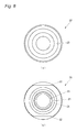
- Fig. 8(a) is a plan view of the housing 20.
- Fig. 8(b) is a bottom view of the housing 20.
- the housing 20 includes a screw portion 21 to be fixed to the screw hole 113a of the arm 113, a tool contact portion 22 which is grasped by a tool such as a wrench at the time of rotating the screw portion 21 with respect to the screw hole 113a of the arm 113, and a holder housing portion 23 in which the holder 40 is housed. Further, the housing 20 is provided with screw holes 24 into which the bolts 12 with hexagon holes are respectively screwed, a groove 25 into which the O ring 14 is fit, and a groove 26 into which the O ring 16 is fit.
- the housing 20 is configured to be fixed to the arm 113 of the industrial robot 100, that is, the machine body and hence constitutes a fixing member of this invention.
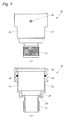
- Fig. 9(a) is a front view of the holder 40.
- Fig. 9(b) is a front sectional view of the holder 40.
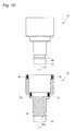
- Fig. 10(a) is a side view of the holder 40.
- Fig. 10(b) is a side sectional view of the holder 40.
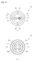
- Fig. 11 (a) is a plan view of the holder 40.
- Fig. 11(b) is a bottom view of the holder 40.
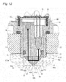
- Fig. 12 is a diagram showing an optical path 10a from the white LED 72 to the RGB sensor 73.
- the holder 40 includes a prism housing portion 41 for housing the right-angle prism 61, a prism housing portion 42 for housing the right-angle prism 62, an LED housing portion 43 for housing the white LED 72, and an RGB sensor housing portion 44 for housing the RGB sensor 73. Further, the holder 40 is provided with a hole 45 penetrating the prism housing portion 41 and the LED housing portion 43, a hole 46 penetrating the prism housing portion 42 and the RGB sensor housing portion 44, screw holes 47 in which the screws 11 are threaded, screw holes 48 in which the bolts 13 with hexagon holes are threaded, and a groove 49 in which the O ring 15 is fitted.
- the prism housing portion 41 includes two walls 41 a sandwiching the right-angle prism 61 therebetween.
- the right-angle prism 61 is fixed to the walls 41 a by means of adhesive.
- the prism housing portion 42 includes two walls 42a sandwiching the right-angle prism 62 therebetween.
- the right-angle prism 62 is fixed to the walls 42a by means of adhesive.
- the holder 40 surrounds at least a part of the optical path 10a from the white LED 72 to the RGB sensor 73 by means of the LED housing portion 43, the hole 45, the prism housing portion 41, the prism housing portion 42, the hole 46 and the RGB sensor housing portion 44, thereby constituting an optical path surrounding portion according to this invention.
- the surface of the holder 40 is treated to a treatment for preventing light reflection such as a black alumite treatment for matting.
- the holder 40 supports the white LED 72 and the RGB sensor 73 via the circuit board 71. Further, the holder 40 directly supports the gap forming member 60.
- the oil gap 60a of the gap forming member 60 is disposed on the optical path 10a from the white LED 72 to the RGB sensor 73.
- the right-angle prisms 61, 62 transmit light emitted from the white LED 72.
- the right-angle prism 61 is provided with a light incident surface 61a on which light emitted from the white LED 72 is made incident, a light reflection surface 61 b which reflects the light entered from the light incident surface 61 a in a manner of bending the propagation direction of the light by 90 degrees, and a light emission surface 61c which emits the light reflected by the light reflection surface 61b.
- the right-angle prism 62 is provided with a light incident surface 62a on which light emitted from the light emission surface 61 c of the right-angle prism 61 is made incident, a light reflection surface 62b which reflects the light entered from the light incident surface 62a in a manner of bending the propagation direction of the light by 90 degrees, and a light emission surface 62c which emits the light reflected by the light reflection surface 62b.
- Each of the light incident surface 61 a, the light reflection surface 61b and the light emission surface 61 c of the right-angle prism 61 and the light incident surface 62a, the light reflection surface 62b and the light emission surface 62c of the right-angle prism 62 is optically polished. Further, each of the light reflection surface 61b of the right-angle prism 61 and the light reflection surface 62b of the right-angle prism 62 is provided with an aluminum deposition film. Furthermore, an SiO2 film is formed on the aluminum deposition film in order to protect the aluminum deposition film which is low in a degree of hardness and an adhesive force.
- the optical path 10a is bent by 90 degrees by the light reflection surface 61 b of the right-angle prism 61 and also bent by 90 degrees by the light reflection surface 62b of the right-angle prism 62. That is, the optical path 10a is bent by 180 degrees by the gap forming member 60.
- the detection accuracy of the colors of the contaminant within the lubricant 131 a degrades.
- the length of the oil gap 60a is too long, the light emitted from the white LED 72 is excessively absorbed by the contaminant within the lubricant 131a within the oil gap 60a and hence unlikely reaches the RGB sensor 73.
- the detection accuracy of the colors of the contaminant within the lubricant 131a also degrades.
- the length of the oil gap 60a is set suitably so that the detection accuracy of the colors of the contaminant within the lubricant 131 a becomes high.
- a distance between the light emission surface 61 c of the right-angle prism 61 and the light incident surface 62a of the right-angle prism 62, that is, the length of the oil gap 60a is 1 mm, for example.
- the white LED 72 is an electronic component which emits white light and constitutes a light emitting element according to this invention.
- NSPW500GS-K1 manufactured by Nichia Corporation, for example, may be employed.
- the RGB sensor 73 is an electronic component which detects the colors of the received light and constitutes a color light reception element according to this invention.
- S9032-02 manufactured by Hamamatsu Photonics K.K., for example, may be employed.
- the connector 78 is configured in a manner that the connector 95 of the external device at the outside of the lubricant deterioration sensor 139b is connected thereto so as to be supplied with electric power via the connector 95 from the external device, and the detection result of the lubricant deterioration sensor 139b is outputted as an electric signal to the external device via the connector 95.
- Fig. 13(a) is a front view of the holder cap 50.
- Fig. 13(b) is a front sectional view of the holder cap 50.
- Fig. 14(a) is a plan view of the holder cap 50.
- Fig. 14(b) is a bottom view of the holder cap 50.
- the holder cap 50 is provided with a tool contact portion 51 for contacting with a tool such as a hexagonal wrench at the time of rotating the supporting member 30 with respect to the housing 20.
- the tool contact portion 51 is a portion for receiving a rotational driving force of the supporting member 30 with respect to the housing 20 from the outside by a contact force, and constitutes a rotational driving force receiving portion according to this invention.
- the tool contact portion 51 is disposed at a position not contacting with the lubricant 131 a when the housing 20 is fixed to the arm 113.
- the holder cap 50 is provided with a hole 52 in which the connector 78 is inserted and holes 53 in which the bolts 13 with hexagon holes are inserted.
- the surface of the holder cap 50 is treated to the treatment for preventing light reflection such as the black alumite treatment for matting.
- the bolts 12 with hexagon holes are configured so as to prevent the rotation of the supporting member 30 with respect to the housing 20 by contacting with both the supporting member 30 and the housing 20, and constitutes a rotation preventing member according to this invention.
- the bolt 12 with a hexagon hole has a tool contact portion 12a for contacting with a tool such as the hexagonal wrench.
- the tool contact portion 12a is a portion for receiving a driving force for contacting with both the supporting member 30 and the housing 20 from the outside by a contact force, and constitutes a contact driving force receiving portion according to this invention.
- the tool contact portion 12a is disposed at a position not contacting with the lubricant 131 a when the housing 20 is fixed to the arm 113.
- the assembling method of the lubricant deterioration sensor 139a will be explained.
- the explanation is made hereinafter as to the lubricant deterioration sensor 139b, the configuration of each of the lubricant deterioration sensors such as the lubricant deterioration sensors 137a, 137b, 139a other than the lubricant deterioration sensor 139b is substantially same.
- adhesive is pasted on the surface plane of the prism housing portion 41 of the holder 40 to be made in contact with the light incident surface 61 a of the right-angle prism 61, and also adhesive is pasted on the two surface planes of the right-angle prism 61 to be made in contact with the two walls 41 a of the prism housing portion 41. Then, the right-angle prism 61 is fixed to the prism housing portion 41 by the adhesive.
- adhesive is pasted on the surface plane of the prism housing portion 42 of the holder 40 to be made in contact with the light emission surface 62c of the right-angle prism 62, and also adhesive is pasted on the two surface planes of the right-angle prism 62 to be made in contact with the two walls 42a of the prism housing portion 42. Then, the right-angle prism 62 is fixed to the prism housing portion 42 by the adhesive. Furthermore, the white LED 72 is fixed to the LED housing portion 43 of the holder 40 by means of adhesive.
- the circuit board 71 mounting the RGB sensor 73 thereon is fixed to the holder 40 by means of the screws 11, and the white LED 72 is fixed to the circuit board 71 by means of soldering. Further, various kinds of electronic components such as the connector 78 are assembled, thereby supporting the electronic component group 70 by the holder 40.
- the holder cap 50 is fixed to the holder 40 by means of the bolts 13 with hexagon holes.
- the holder 40 attached with the O ring 15 is fixed, by means of the bolts 12 with hexagon holes, to the holder housing portion 23 of the housing 20 attached with the O ring 14 and the O ring 16.
- the tool contact portion 22 of the housing 20 is grasped by a tool and the screw portion 21 of the housing 20 is threaded into the screw hole 113a of the arm 113, thereby fixing the lubricant deterioration sensor 139b to the arm 113.
- the connector 95 of the external device at the outside of the lubricant deterioration sensor 139b is connected to the connector 78.
- the configuration of each of the lubricant deterioration sensors such as the lubricant deterioration sensors 137a, 137b, 139a other than the lubricant deterioration sensor 139b is substantially same.
- the lubricant deterioration sensor 139b emits white light from the white LED 72 in response to electric power supplied from the external device via the connector 78.
- the lubricant deterioration sensor 139b outputs light amounts of respective colors RGB of the light received by the RGB sensor 73 as an electric signal to the external device via the connector 78.
- the lubricant deterioration sensor 139b may additionally mount another sensor other than the RGB sensor 73.
- the temperature detected by the temperature sensor can also be outputted as an electric signal to the external device via the connector 78.
- the external device of the lubricant deterioration sensor 139b can specify the kinds and amounts of the contaminant within the lubricant 131a of the reducer 131 based on the colors detected by the RGB sensor 73. That is, the lubricant deterioration sensor 139b can detect the deterioration degree of the lubricant 131 a by detecting the colors of the contaminant within the lubricant 131 a.
- Fig. 15 is a diagram showing an example of the relation between the direction of the opening 60b of the oil gap 60a with respect to the flow of the lubricant 131a and a color difference ⁇ E of the colors detected by the RGB sensor 73 with respect to black.
- Fig. 16(a) is a diagram showing a state that the direction of the opening 60b of the oil gap 60a with respect to the flow of the lubricant 131 a is 0 degree.
- Fig. 16(b) is a diagram showing a state that the direction of the opening 60b of the oil gap 60a with respect to the flow of the lubricant 131 a is 45 degrees.
- Fig. 16(c) is a diagram showing a state that the direction of the opening 60b of the oil gap 60a with respect to the flow of the lubricant 131 a is 90 degrees.
- the color difference ⁇ E of the colors detected by the RGB sensor 73 with respect to black can be calculated by an expression shown by the following Math. 1 by using the respective values of the colors RGB detected by the RGB sensor 73.
- a "static state” represents a time period where the flow of the lubricant 131 a stops.
- the direction of the opening 60b of the oil gap 60a with respect to the flow of the lubricant 131a does not influence on the ⁇ E of the colors detected by the RGB sensor 73 with respect to black.
- the ⁇ E of the colors detected by the RGB sensor 73 with respect to black in the "static state” becomes a determination criterion of the relation between the direction of the opening 60b of the oil gap 60a with respect to the flow of the lubricant 131a and the color difference ⁇ E of the colors detected by the RGB sensor 73 with respect to black.
- each of 36 [rpm] and 45 [rpm] represents the rotation speed of the arm 113 with respect to the arm 112 as a revolution number per one minute. Since the lubricant deterioration sensor 139b is attached to the arm 113, this sensor moves within the lubricant 131 a in accordance with the rotation of the arm 113 with respect to the arm 112. Since the lubricant deterioration sensor 139b is attached to the arm 113, this sensor moves within the lubricant 131 a in accordance with the rotation of the arm 113 with respect to the arm 112. In other words, each of 36 [rpm] and 45 [rpm] indirectly represents the speed of the flow of the lubricant 131 a with respect to the lubricant deterioration sensor 139b.
- arrows other than those representing the oil gap 60a represent the flow of the lubricant 131 a.
- the detection accuracy of the deterioration of the lubricant 131a can be determined by the color difference ⁇ E of the colors detected by the RGB sensor 73 with respect to black.
- the detection accuracy of the deterioration of the lubricant 131 a degrades in a case that the rotation speed of the arm 113 with respect to the arm 112 is 45 [rpm] and the direction of the opening 60b of the oil gap 60a with respect to the flow of the lubricant 131 a is 0 degree or 45 degrees.
- the detection accuracy of the deterioration of the lubricant 131a degrades depending on the direction of the opening 60b of the oil gap 60a with respect to the flow of the lubricant 131 a.
- the lubricant deterioration sensor 139b is configured to be adjustable in the direction of the opening 60b of the oil gap 60a.
- each of the bolts 12 with hexagon holes is loosened by a tool inserted into the tool contact portion 12a so that the supporting member 30 becomes rotatable with respect to the housing 20.
- the supporting member 30 is rotated with respect to the housing 20 by the tool inserted into the tool contact portion 51.
- the direction of the opening 60b of the oil gap 60a changes in accordance with the rotation of the supporting member 30 with respect to the housing 20.
- each of the bolts 12 with hexagon holes is fastened by the tool inserted into the tool contact portion 12a so that the rotation of the supporting member 30 becomes impossible with respect to the housing 20.
- each of the lubricant deterioration sensors such as the lubricant deterioration sensor 139b can immediately detect the colors of the contaminant within the lubricant 131 a of the reducer 131. That is, each of the lubricant deterioration sensors can immediately specify the kinds and amounts of the contaminant within the lubricant 131a of the reducer 131 based on the colors detected by the RGB sensor 73, by using the external device such as a computer.
- Each of the lubricant deterioration sensors may be configured that the electronic component group 70 contains an electronic component which specifies the kinds and amounts of the contaminant within the lubricant based on the colors detected by the RGB sensor 73.
- each of the lubricant deterioration sensors of the industrial robot 100 can immediately specify the kinds and amounts of the contaminant within the lubricant 131 a of the reducer 131 based on the colors detected by the RGB sensor 73, by using the external device such as a computer.
- the industrial robot 100 and each of the reducers of the industrial robot 100 can predict a failure.
- additives such as friction reducing agent like organic molybdenum such as MoDTC or MoDTP for reducing the friction of a friction surface, extreme-pressure additive such as SP-based additive for improving extreme-pressure lubricity representing the performance for suppressing the sticking of the friction surface, and dispersing agent such as calcium sulfonate for suppressing the generation and adhesion of sludge.
- friction reducing agent like organic molybdenum such as MoDTC or MoDTP for reducing the friction of a friction surface
- extreme-pressure additive such as SP-based additive for improving extreme-pressure lubricity representing the performance for suppressing the sticking of the friction surface
- dispersing agent such as calcium sulfonate for suppressing the generation and adhesion of sludge.
- Each of the lubricant deterioration sensors can specify, based on the detected colors, not only an amount of ion powder within the lubricant 131 a but also a deterioration degree of the base oil and increase of the contaminant such as sludge due to the reduction of various kinds of additive added to the lubricant 131 a.
- each of the industrial robot 100 and the reducers of the industrial robot 100 can improve the prediction accuracy of a failure as compared with a technique where a failure of the reducer is predicted only based on a density of iron powder.
- the lubricant 131a does not contain molybdenum such as MoDTC or MoDTP as the additive.
- the inventors of the present application have performed the comparative experimentation as to the degradation of the performance of the lubricant deterioration sensor between the lubricant 131 a containing molybdenum as the additive and the lubricant 131 a not containing molybdenum as the additive.
- the lubricant used in this experimentation as the lubricant 131 a containing molybdenum as the additive contains organic molybdenum as the friction reducing agent, the extreme-pressure additive, the dispersing agent and antioxidant each in a rage of 0.1 % to 10% as the additive.
- the lubricant used in this experimentation as the lubricant 131a not containing molybdenum as the additive differs only in a point that the organic molybdenum as the friction reducing agent is not contained.
- the results of this experimentation are shown in Figs. 17 and 18 .
- Fig. 17(a) is a table showing the experimentation result of the chorological change of the difference ⁇ E in a case where the lubricant 131 a contains molybdenum as the additive.
- Fig. 17(b) is a graph of the experimentation result shown in Fig. 17(a) .
- Fig. 18(a) is a table showing the experimentation result of the chorological change of the difference ⁇ E in a case where the lubricant 131a does not contain molybdenum as the additive.
- Fig. 18(b) is a graph of the experimentation result shown in Fig. 18(a) .
- a rated conversion time was obtained in a manner that a time period during which the device for the experimentation was actually driven was converted into a time period of a case that the output rotation speed is 15 rpm and the load torque is the rated torque of the reducer 131, based on the output rotation speed and the load torque of the reducer 131 in a case where the device for the experimentation was actually driven.
- the life time of the reducer 131 is defined as 6,000 hours in a case where the reducer 131 is continuously driven under a condition that the output rotation speed is 15 rpm and the load torque is the rated torque of the reducer 131.
- the sampling measurement was performed in a manner that the lubricant 131 a was drained from the device for the experimentation each time of the measurement, and a color difference ⁇ E of the colors of the lubricant 131a drained from the device for the experimentation with respect to black was measured by using a lubricant deterioration sensor like the lubricant deterioration sensor 139b. Further, the real time measurement was performed in a manner that the color difference ⁇ E of the colors of the lubricant 131a within the device for the experimentation with respect to black was measured by using the lubricant deterioration sensor 139b attached to the device for the experimentation.
- the experimentation result of the sampling measurement represents the state of the lubricant 131a quite precisely.
- the right-angle prisms 61, 62 of the gap forming member 60 of the lubricant deterioration sensor 139b used at the time of the real time measurement are always made in contact with the lubricant 131 a, sludge generated by the deterioration of the lubricant 131 a adheres to the prisms.
- the experimentation result of the real time measurement is influenced by the sludge adhered to the right-angle prisms 61, 62.
- a difference between the experimentation result of the sampling measurement and the experimentation result of the real time measurement represents a degree of the influence of the sludge adhered to the right-angle prisms 61,62.
- each of the industrial robot 100 and the reducers of the industrial robot 100 can prevent a phenomenon that molybdenum adheres to the right-angle prisms of the gap forming member as the sludge.
- generation of the adhesion of the sludge to the right-angle prisms of the gap forming member can be suppressed and hence the degradation of the performance of the lubricant deterioration sensor can be suppressed.
- each of the industrial robot 100 and the reducers of the industrial robot 100 can prevent the degradation of the performance of the lubricant deterioration sensor which can immediately specify the kinds and amounts of the contaminant within the lubricant 131 a.
- the housing 20 supports the supporting member 30 so as to be rotatable so that the direction of the opening 60b of the oil gap 60a changes when the supporting member 30 rotates.
- the direction of the opening 60b of the oil gap 60a at the time of fixing the housing 20 to the industrial robot 100 can be adjusted so that the detection accuracy of the deterioration of the lubricant 131 a of the industrial robot 100 becomes high.
- each of the industrial robot 100 and the reducers of the industrial robot 100 can predict a failure with a high accuracy.
- the supporting member 30 includes the tool contact portion 51, as the portion for receiving the rotational driving force with respect to the housing 20 from the outside by the contact force, at a position not contacting with the lubricant 131a when the housing 20 is fixed to the industrial robot 100.
- the direction of the opening 60b of the oil gap 60a at the time of fixing the housing 20 to the industrial robot 100 can be adjusted so that the detection accuracy of the deterioration of the lubricant 131 a of the industrial robot 100 becomes high.
- each of the bolts 12 with hexagon holes configured so as to prevent the rotation of the supporting member 30 with respect to the housing 20 by contacting with both the supporting member 30 and the housing 20, includes the tool contact portion 12a, as the portion for receiving the driving force for contacting with both the supporting member 30 and the housing 20 from the outside by the contact force, at the position not contacting with the lubricant 131 a when the housing 20 is fixed to the industrial robot 100.
- the direction of the opening 60b of the oil gap 60a at the time of fixing the housing 20 to the industrial robot 100 can be fixed so that the detection accuracy of the deterioration of the lubricant 131 a of the industrial robot 100 becomes high.
- each of the lubricant deterioration sensors since the light emitting element is the white LED for emitting white light, the sensor can be miniaturized as compared with a configuration where the light emitting element is a lamp other than an LED, for example.
- the light emitting element according to this invention may be one other than the white LED.
- the light emitting element may be a lamp other than an LED.
- the light emitting element may be configured to include a red LED or a red lamp other than an LED, a green LED or a green lamp other than an LED and a blue LED or a blue lamp other than an LED, to thereby emit white light by composing light of respective colors emitted from these LEDs or these lamps other than LEDs.
- the gap forming member 60 is provided with the light reflection surfaces 61b, 62b for bending the optical path 10a.
- the entire configuration can be miniaturized by disposing the white LED 72 and the RGB sensor 73 close to each other.
- the gap forming member 60 has a function of bending the optical path 10a as well as a function of forming the oil gap 60a.
- the number of the components can be reduced as compared with a configuration where a member for bending the optical path 10a is separately provided in place of the gap forming member 60.
- each of the industrial robot 100 and the reducers of the industrial robot 100 can be miniaturized and also reduce the number of the components.
- each of the lubricant deterioration sensors is configured in a manner that the gap forming member 60 is formed by the two right-angle prisms 61, 62 respectively provided with the light reflection surfaces 61 b, 62b each for bending the optical path 10a by 90 degrees, and that the optical path 10a is bent by 180 degrees by the light reflection surfaces 61 b, 62b of the two right-angle prisms 61, 62 and the oil gap 60a is formed between the two right-angle prisms 61, 62.
- the sensor can be miniaturized with the simple configuration having a small number of the components.
- each of the industrial robot 100 and the reducers of the industrial robot 100 can be miniaturized with the simple configuration having the small number of the components.
- each of the lubricant deterioration sensors is configured in a manner that the sensor has the holder 40 surrounding at least a part of the optical path 10a and the surface of the holder 40 is treated to the treatment for preventing light reflection.
- the RGB sensor 73 can be prevented from receiving unnecessary reflection light.
- each of the lubricant deterioration sensors can improve the detection accuracy of the colors of the contaminant within the lubricant 131 a. Accordingly, each of the industrial robot 100 and the reducers of the industrial robot 100 can improve the prediction accuracy of a failure.
- an oil repelling treatment may be performed on the surface planes of the gap forming member 60 forming the oil gap 60a, that is, the light emission surface 61 c of the right-angle prism 61 and the light incident surface 62a of the right-angle prism 62.
- the lubricant 131a flows through the oil gap 60a easily.
- the detection accuracy of the colors of the contaminant within the lubricant 131 a can be improved. Furthermore, in each of the lubricant deterioration sensors, when each of the light emission surface 61 c of the right-angle prism 61 and the light incident surface 62a of the right-angle prism 62 is treated to the oil repelling treatment, dirt is unlikely adhered to each of the light emission surface 61 c of the right-angle prism 61 and the light incident surface 62a of the right-angle prism 62.
- each of the industrial robot 100 and the reducers of the industrial robot 100 can improve the prediction accuracy of a failure.
- the prediction accuracy of a failure of the reducer can be improved by jointly using the lubricant deterioration sensor according to this invention, the temperature sensor for measuring the temperature of the lubricant and a monitoring mechanism for a current value of the motor etc.
- each of the right-angle prisms 61, 62 of the gap forming member 60 is made of glass in this embodiment, each of them may be formed by material other than glass such as silicon resin.
- silicon resin When each of the prisms 61, 62 is formed by silicon resin, dirt can be unlikely adhered to the surface planes thereof forming the oil gap 60a.
- the gap forming member 60 is configured by the two right-angle prisms 61, 62 in this embodiment, the gap forming member may be configured by three or more prisms.
- the white LED 72 and the RGB sensor 73 may be configured in an arrangement other than that explained in this embodiment.
- the optical path 10a from the white LED 72 to the RGB sensor 73 may be straight
- the optical path 10a may be bent by employing a configuration other than the right-angle prisms.
- a battery such as a battery cell may be used as an electric power supply means, and a wireless communication may be employed as a means for outputting the detection result to the external device.
- each of the lubricant deterioration sensors is not limited to that shown in this embodiment, and preferably may be set suitably according to the usage etc. of the industrial robot 100.
- the industrial robot is used in the embodiment as the machine according to this invention, the machine other than the industrial robot may be used.
- Japanese Patent Application Japanese Patent Application No. 2011-287000 filed on December 27, 2011 , the content of which is incorporated herein by reference.
- the machine which can suppress the degradation of performance of the lubricant deterioration sensor that can immediately specify the kinds and amounts of the contaminant within the lubricant.
Landscapes
- Physics & Mathematics (AREA)
- General Health & Medical Sciences (AREA)
- Life Sciences & Earth Sciences (AREA)
- Chemical & Material Sciences (AREA)
- Analytical Chemistry (AREA)
- Biochemistry (AREA)
- Health & Medical Sciences (AREA)
- General Physics & Mathematics (AREA)
- Immunology (AREA)
- Pathology (AREA)
- Spectroscopy & Molecular Physics (AREA)
- Investigating Or Analysing Materials By Optical Means (AREA)
- Manipulator (AREA)
Abstract
Description
- The present invention relates to a machine provided with a lubricant deterioration sensor for detecting the deterioration of lubricant.
- Conventionally, as a lubricant deterioration sensor for detecting the deterioration of lubricant of a machine, an oil deterioration degree sensor has been known. In this sensor, an oil entering gap portion for entering lubricant therein is formed on an optical path from an infrared LED (Light Emitting Diode) to a photo diode. Then, an amount of light absorption by the lubricant within the oil entering gap portion with respect to light emitted from the infrared LED is measured according to a light reception amount of the photo diode, to thereby determine a deterioration degree of the lubricant related to the light absorption amount thus measured (see patent literatures 1 and 2, for example).
- However, the oil deterioration degree sensor described in each of the patent literatures 1 and 2 has a problem that, although a density of insoluble content within the lubricant can be measured as the deterioration degree of the lubricant, kinds of contaminant within the lubricant can not be specified.
- As a technique of specifying the kinds of contaminant within lubricant, a technique has been known in which an LED irradiates light toward a membrane filter having been used to filter the lubricant. Then, a light reception element converts reflection light from the contaminant on the membrane filter into digital values of RGB, to thereby specify the kinds of contaminant within the lubricant based on the RGB digital values thus converted (see non-patent literatures 1 and 2, for example).
- As the lubricant for a machine, there is known one in which organic molybdenum (Mo) such as molybdenum dithiocarbamate (MoDTC) or molybdenum dithiophosphate (MoDTP) is added as friction reducing agent for reducing the friction of the friction surface of the machine (see patent literatures 3 and 4, for example).
-
- Patent Literature 1:
JP-A-7-146233 - Patent Literature 2:
JP-A-10-104160 - Patent Literature 3:
JP-A-2004-339411 - Patent Literature 4:
JP-A-2010-24355 -
- Non-Patent Literature 1: Tomohiko Yamaguchi and four others, "METHOD OF DISCRIMINATING HUE OF CONTAMINANT WITHIN LUBRICANT", Fukui University, Faculty of Engineering, Research Report, March 2003,
- Non-Patent Literature 2: Tomonori Honda, "DETERIORATION DIAGNOSIS OF LUBRICANT INSPECTION TECHNOLOGY", Journal of Japan Society for Precision Engineering, 2009,
- Accordingly, an object of this invention is to provide a machine which can suppress the degradation of performance of a lubricant deterioration sensor that can immediately specify the kinds and amounts of contaminant within lubricant.
- According to this invention, there is provided with a machine which is configured to detect deterioration of lubricant, including:
- a machine body;
- lubricant for reducing friction generated at a movable portion of the machine body; and
- a lubricant deterioration sensor which is mounted in the machine body and configured to detect deterioration of the lubricant,
- a light emitting element configured to emit light;
- a color light reception element configured to detect color of received light; and
- a gap forming member forming an oil gap being a gap in which the lubricant enters,
- The lubricant deterioration sensor may further includes a supporting member which supports the light emitting element, the color light reception element and the gap forming member, and a fixing member to be fixed to the machine body. The fixing member may support the supporting member so as to be rotatable so that a direction of an opening of the oil gap changes when the supporting member rotates.
- The supporting member may be provided with a rotational driving force receiving portion which is a portion for receiving a rotational driving force with respect to the supporting member from outside by a contact force, at a position where the rotational driving force receiving portion does not contact with the lubricant in a state where the fixing member is fixed to the machine body.
- The lubricant deterioration sensor may further include a rotation preventing member preventing a rotation of the supporting member with respect to the fixing member by contacting with both the supporting member and the fixing member. The rotation preventing member may include a contact driving force receiving portion which is a portion for receiving a driving force for contacting with both the supporting member and the fixing member from outside by a contact force, at a position where the contact driving force receiving portion does not contact with the lubricant in a state where the fixing member is fixed to the machine body.
- The light emitting element may be a white LED which emits white light.
- The gap forming member may have a reflection surface for bending the optical path.
- The gap forming member may include two right-angle prisms each provided with the reflection surface for bending the optical path by 90 degrees, whereby the optical path is bent by 180 degrees by the reflection surfaces of the two right-angle prisms. The oil gap may be formed between the two right-angle prisms.
- The supporting member may have an optical path surrounding portion which surrounds at least a part of the optical path, and the optical path surrounding portion may have a surface which is treated to a treatment for preventing light reflection.
- The surface of the gap forming member forming the oil gap may be treated to an oil repelling treatment.
- The machine may be an industrial robot,
the machine body may include an arm and a reducer used at an articular portion of the arm, and
the lubricant may be lubricant for the reducer. - In the lubricant deterioration sensor for the machine according to this invention, the color light reception element detects colors with respect to the light having wavelengths not absorbed by the contaminant such as ion powder within the lubricant at the oil gap among the light emitted by the light emitting element. Thus, colors of the contaminant within the lubricant can be detected immediately. That is, the lubricant deterioration sensor for the machine according to this invention can immediately specify the kinds and amounts of the contaminant within the lubricant based on the colors detected by the color light reception element.
- Further, in the machine according to this invention, since the lubricant does not contain molybdenum as additive, molybdenum can be prevented from adhering to the gap forming member as sludge. Thus, the machine according to this invention can suppress the generation of the adherence of the sludge to the gap forming member and hence the degradation of the performance of the lubricant deterioration sensor can be suppressed.
- As a result, the machine according to this invention can prevent the degradation of the performance of the lubricant deterioration sensor which can immediately specify the kinds and amounts of the contaminant within the lubricant.
- In the machine according to this invention, in a case where the fixing member is fixed to the machine body, the direction of the opening of the oil gap in a state where the fixing member is fixed to the machine body can be adjusted so that the detection accuracy of the deterioration of the lubricant by the lubricant deterioration sensor becomes high.
- In the machine according to this invention, after the fixing member is fixed to the machine body, the direction of the opening of the oil gap in the state where the fixing member is fixed to the machine body can be adjusted so that the detection accuracy of the deterioration of the lubricant by the lubricant deterioration sensor becomes high.
- In the machine according to this invention, after the fixing member is fixed to the machine body, the direction of the opening of the oil gap in the state where the fixing member is fixed to the machine body can be fixed so that the detection accuracy of the deterioration of the lubricant by the lubricant deterioration sensor becomes high.
- In the machine according to this invention, the lubricant deterioration sensor can be miniaturized as compared with a configuration where the light emitting element is a lamp other than an LED, for example. Thus, the machine according to this invention can be miniaturized.
- In the machine according to this invention, as compared with a configuration where the optical path from the light emitting element to the color light reception element is straight, the lubricant deterioration sensor can be miniaturized by disposing the light emitting element and the color light reception element close to each other. Further, the gap forming member has a function of bending the optical path as well as a function of forming the oil gap. Thus, the number of the components of the lubricant deterioration sensor can be reduced as compared with a configuration where a member for bending the optical path is separately provided in place of the gap forming member. Thus, the machine according to this invention can be miniaturized and further reduce the number of the components.
- In the machine according to this invention, the lubricant deterioration sensor can be miniaturized with a simple configuration having a small number of the components. Thus, the machine according to this invention can be miniaturized with a simple configuration having a small number of the components.
- In the machine according to this invention, the color light reception element is prevented from receiving unnecessary reflection light. Thus, the detection accuracy of the colors of the contaminant within the lubricant by the lubricant deterioration sensor can be improved as compared with a configuration where the color light reception element receives unnecessary reflection light. Thus, the machine according to this invention can improve the prediction accuracy of a failure.
- Since the machine according to this invention is configured to easily flow the lubricant through the oil gap, the detection accuracy of the colors of the contaminant within the lubricant by the lubricant deterioration sensor can be improved as compared with a configuration where the lubricant likely remains at the oil gap. Further, in the machine according to this invention, when the surface forming the oil gap is treated to the oil repelling treatment, dirt is unlikely adhered to the surface forming the oil gap. Thus, the degradation of the detection accuracy of the colors of the contaminant within the lubricant by the lubricant deterioration sensor due to the adhesion of dirt can be suppressed. Thus, the machine according to this invention can improve the prediction accuracy of a failure.
- The industrial robot according to this invention can prevent the degradation of the performance of the lubricant deterioration sensor which can immediately specify the kinds and amounts of the contaminant within the lubricant. Thus, the industrial robot according to this invention can predict an immediate failure for a long time.
- It is possible to suppress the degradation of performance of the lubricant deterioration sensor which can immediately specify the kinds and amounts of the contaminant within the lubricant.
-
- [
Fig. 1] Fig. 1 is a side view of an industrial robot according to an embodiment of this invention. - [
Fig. 2] Fig. 2 is a sectional view of the articular portion of the industrial robot shown inFig. 1 . - [
Fig. 3] Fig. 3 is a front view of a lubricant deterioration sensor shown inFig. 2 . - [
Fig. 4] Fig. 4 is a front sectional view of the lubricant deterioration sensor shown inFig. 3 in an attached state to an arm. - [
Fig. 5] Fig. 5(a) is a plan view of the lubricant deterioration sensor shown inFig. 3 .Fig. 5(b) is a bottom view of the lubricant deterioration sensor shown inFig. 3 . - [
Fig. 6] Fig. 6(a) is a front view of a housing shown inFig. 3 .Fig. 6(b) is a front sectional view of the housing shown inFig. 3 . - [
Fig. 7] Fig. 7(a) is a side view of the housing shown inFig. 3 .Fig. 7(b) is a side sectional view of the housing shown inFig. 3 . - [
Fig. 8] Fig. 8(a) is a plan view of the housing shown inFig. 3 .Fig. 8(b) is a bottom view of the housing shown inFig. 3 . - [
Fig. 9] Fig. 9(a) is a front view of a holder shown inFig. 3 .Fig. 9(b) is a front sectional view of the holder shown inFig. 3 . - [
Fig. 10] Fig. 10(a) is a side view of the holder shown inFig. 3 .Fig. 10(b) is a side sectional view of the holder shown inFig. 3 . - [
Fig. 11] Fig. 11 (a) is a plan view of the holder shown inFig. 3 .Fig. 11 (b) is a bottom view of the holder shown inFig. 3 . - [
Fig. 12] Fig. 12 is a diagram showing an optical path from a white LED to an RGB sensor shown inFig. 4 . - [
Fig. 13] Fig. 13(a) is a front view of a holder cap shown inFig. 3 .Fig. 13(b) is a front sectional view of the holder cap shown inFig. 3 . - [
Fig. 14] Fig. 14(a) is a plan view of the holder cap shown inFig. 3 .Fig. 14(b) is a bottom view of the holder cap shown inFig. 3 . - [
Fig. 15] Fig. 15 is a diagram showing an example of the relation between the direction of the opening of an oil gap shown inFig. 3 with respect to the flow of lubricant and a color difference ΔE of colors detected by the RGB sensor with respect to black. - [
Fig. 16] Fig. 16(a) is a diagram showing a state that the direction of the opening of the oil gap shown inFig. 3 with respect to the flow of the lubricant is 0 degree.Fig. 16(b) is a diagram showing a state that the direction of the opening of the oil gap shown inFig. 3 with respect to the flow of the lubricant is 45 degrees.Fig. 16(c) is a diagram showing a state that the direction of the opening of the oil gap shown inFig. 3 with respect to the flow of the lubricant is 90 degrees. - [
Fig. 17] Fig. 17(a) is a table showing the experimentation result of the chronological change of the color difference ΔE in a case where the lubricant shown inFig. 2 contains molybdenum as additive.Fig. 17(b) is a graph of the experimentation result shown inFig. 17(a) . - [
Fig. 18] Fig. 18(a) is a table showing the experimentation result of the chronological change of the color difference ΔE in a case where the lubricant shown inFig. 2 does not contain molybdenum as additive.Fig. 18(b) is a graph of the experimentation result shown inFig. 18(a) . - Since the technique described in each of the non-patent literatures 1 and 2 requires to drain lubricant from a machine and filter the lubricant by a membrane filter, there arises a problem of lacking immediacy.
- In view of this, the inventors of the present application have developed a lubricant deterioration sensor which can immediately specify the kinds and amounts of contaminant within the lubricant of a machine. This lubricant deterioration sensor (hereinafter referred to as a "new sensor") is a lubricant deterioration sensor which is mounted in a machine and detects the deterioration of the lubricant of the machine. This sensor includes a light emitting element which emits light, a color light reception element which detects color of received light, and a gap forming member at which an oil gap as a gap for entering the lubricant therein is formed, wherein the gap forming member transmits the light emitted from the light emitting element, and the oil gap is disposed on an optical path from the light emitting element to the color light reception element.
- However, the inventors of the present application have found that when the new sensor is continuously mounted and used in the machine, the accuracy of the new sensor for specifying the kinds and amounts of contaminant within the lubricant degrades, that is, the performance of the new sensor degrades.
- Then, the inventors of the present application have investigated a cause of the degradation of the performance of the new sensor. As a result of the investigation, the inventors of the present application have ascertained that the degradation of the performance of the new sensor is caused by a fact that sludge (sediment) generated by the deterioration of the lubricant adheres to the gap forming member.
- Thus, the inventors of the present application have analyzed the sludge adhered to the gap forming member in order to ascertain the cause of the generation of the sludge. As a result, the inventors of the present application have ascertained that molybdenum (Mo) is contained in the sludge adhered to the gap forming member.
- Then, in order to investigate whether or not molybdenum contained in the lubricant as additive is a cause of the degradation of the performance of the new sensor, the inventors of the present application have performed comparative experimentation as to the degradation of the performance of the new sensor between the lubricant containing molybdenum as the additive and the lubricant not containing molybdenum as the additive. As a result, the inventors of the present application have concluded that molybdenum contained in the lubricant as the additive is at least one cause of the degradation of the performance of the new sensor.
- Accordingly, an object of this invention is to provide a machine which can suppress the degradation of performance of a lubricant deterioration sensor that can immediately specify the kinds and amounts of contaminant within lubricant.
- Hereinafter, an embodiment of this invention will be explained with reference to drawings.
- First, the configuration of an industrial robot as a machine according to this embodiment will be explained.
-
Fig. 1 is a side view of theindustrial robot 100 according to this embodiment. - As shown in
Fig. 1 , theindustrial robot 100 includes anattachment portion 111 to be attached to a placingportion 900 such as a floor or a ceiling,arms 112 to 116, anarticular portion 120 for connecting between theattachment portion 111 and thearm 112, anarticular portion 130 for connecting between thearm 112 and anarm 113, anarticular portion 140 for connecting between thearm 113 and anarm 114, anarticular portion 150 for connecting between thearm 114 and anarm 115, anarticular portion 160 for connecting between thearm 115 and anarm 116, and anarticular portion 170 for connecting between thearm 116 and a not-shown hand. - Of the
industrial robot 100, portions except forlubricant 131 a and the lubricant deterioration sensors such aslubricant deterioration sensors -
Fig. 2 is a sectional view of thearticular portion 130. Hereinafter, although the explanation is made as to thearticular portion 130, the operation of each of thearticular portions - As shown in
Fig. 2 , thearticular portion 130 includes areducer 131 for connecting between thearm 112 and thearm 113, amotor 138 fixed to thearm 112 by means ofbolts 138a, and thelubricant deterioration sensors lubricant 131 a for reducing friction generated at the movable portions of thereducer 131. - The
reducer 131 includes areducer body 132 and thelubricant deterioration sensors lubricant 131 a of thereducer body 132. - The
reducer body 132 includes acase 133 fixed to thearm 112 by means ofbolts 133a, a supportingbody 134 fixed to thearm 113 by means ofbolts 134a, agear 135a fixed to the output shaft of themotor 138, threegears 135b which are disposed around the center axis of thereducer 131 with a constant interval therebetween and mesh with thegear 135a, three crankshafts 135c which are disposed around the center axis of thereducer 131 with a constant interval therebetween and fixed to thegears 135b, respectively, and twoexternal gears 136 which mesh with internal gears provided at thecase 133. - The supporting
body 134 is rotatably supported by thecase 133 viabearings 133b. Aseal member 133c for preventing leakage of thelubricant 131 a is provided between thecase 133 and the supportingbody 134. - Each of the
crank shafts 135c is rotatably supported by the supportingbody 134 viabearings 134b and further rotatably supported by theexternal gears 136 viabearings 136a. - Each of the
lubricant deterioration sensor 137a and thelubricant deterioration sensor 137b is fixed to thecase 133. Thelubricant deterioration sensor 139a is fixed to thearm 112. Thelubricant deterioration sensor 139b is fixed to thearm 113. -
Fig. 3 is a front view of thelubricant deterioration sensor 139b.Fig. 4 is a front sectional view of thelubricant deterioration sensor 139b in an attached state to thearm 113.Fig. 5(a) is a plan view of thelubricant deterioration sensor 139b.Fig. 5(b) is a bottom view of thelubricant deterioration sensor 139b. Although the explanation is made hereinafter as to thelubricant deterioration sensor 139b, the configuration of each of the lubricant deterioration sensors such as thelubricant deterioration sensors lubricant deterioration sensor 139b is substantially same. - As shown in
Figs. 3 to 5 , thelubricant deterioration sensor 139b includes ahousing 20 made of aluminum alloy for supporting the respective components of thelubricant deterioration sensor 139b, a supportingmember 30 for supporting awhite LED 72, anRGB sensor 73 and agap forming member 60 described later, thegap forming member 60 held by the supportingmember 30, and anelectronic component group 70 having thewhite LED 72 and theRGB sensor 73. - The supporting
member 30 is fixed to thehousing 20 by means ofbolts 12 with hexagon holes. The supportingmember 30 includes aholder 40 made of aluminum alloy, and aholder cap 50 made of aluminum alloy which is fixed to theholder 40 by means ofbolts 13 with hexagon holes. - The
gap forming member 60 is constituted by two right-angle prisms oil gap 60a as a gap for entering thelubricant 131 a therein is formed between the two right-angle prisms - The
electronic component group 70 includes acircuit board 71 fixed to the supportingmember 30 by means ofscrews 11, thewhite LED 72 mounted on thecircuit board 71, theRGB sensor 73 mounted on thecircuit board 71, acircuit board 74 disposed at one surface side of thecircuit board 71 opposing to thewhite LED 72 andRGB sensor 73 side thereof, a plurality ofpillars 75 for fixing thecircuit board 71 and thecircuit board 74, acircuit board 76 disposed on the opposite surface side of thecircuit board 71 with respect to thecircuit board 74, a plurality ofpillars 77 for fixing thecircuit board 74 and thecircuit board 76, and aconnector 78 mounted on one surface side of thecircuit board 76 opposing to thecircuit board 74 side thereof. A plurality of electronic components are mounted on each of thecircuit board 71, thecircuit board 74 and thecircuit board 76. Thecircuit board 71, thecircuit board 74 and thecircuit board 76 are mutually connected electrically. - The
lubricant deterioration sensor 139b includes anO ring 14 for preventing the leakage of thelubricant 131 a from a gap between thehousing 20 and thearm 113, anO ring 15 for preventing the leakage of thelubricant 131 a from a gap between thehousing 20 and theholder 40, and anO ring 16 disposed between thehousing 20 and theholder cap 50. -
Fig. 6(a) is a front view of thehousing 20.Fig. 6(b) is a front sectional view of thehousing 20.Fig. 7(a) is a side view of thehousing 20.Fig. 7(b) is a side sectional view of thehousing 20.Fig. 8(a) is a plan view of thehousing 20.Fig. 8(b) is a bottom view of thehousing 20. - As shown in
Figs. 3 to 8 , thehousing 20 includes ascrew portion 21 to be fixed to thescrew hole 113a of thearm 113, atool contact portion 22 which is grasped by a tool such as a wrench at the time of rotating thescrew portion 21 with respect to thescrew hole 113a of thearm 113, and aholder housing portion 23 in which theholder 40 is housed. Further, thehousing 20 is provided with screw holes 24 into which thebolts 12 with hexagon holes are respectively screwed, agroove 25 into which theO ring 14 is fit, and agroove 26 into which theO ring 16 is fit. Thehousing 20 is configured to be fixed to thearm 113 of theindustrial robot 100, that is, the machine body and hence constitutes a fixing member of this invention. -
Fig. 9(a) is a front view of theholder 40.Fig. 9(b) is a front sectional view of theholder 40.Fig. 10(a) is a side view of theholder 40.Fig. 10(b) is a side sectional view of theholder 40.Fig. 11 (a) is a plan view of theholder 40.Fig. 11(b) is a bottom view of theholder 40.Fig. 12 is a diagram showing anoptical path 10a from thewhite LED 72 to theRGB sensor 73. - As shown in
Figs.3 to 5 andFigs. 9 to 12 , theholder 40 includes aprism housing portion 41 for housing the right-angle prism 61, aprism housing portion 42 for housing the right-angle prism 62, anLED housing portion 43 for housing thewhite LED 72, and an RGBsensor housing portion 44 for housing theRGB sensor 73. Further, theholder 40 is provided with ahole 45 penetrating theprism housing portion 41 and theLED housing portion 43, ahole 46 penetrating theprism housing portion 42 and the RGBsensor housing portion 44, screw holes 47 in which thescrews 11 are threaded, screw holes 48 in which thebolts 13 with hexagon holes are threaded, and agroove 49 in which theO ring 15 is fitted. - The
prism housing portion 41 includes twowalls 41 a sandwiching the right-angle prism 61 therebetween. The right-angle prism 61 is fixed to thewalls 41 a by means of adhesive. Theprism housing portion 42 includes twowalls 42a sandwiching the right-angle prism 62 therebetween. The right-angle prism 62 is fixed to thewalls 42a by means of adhesive. - The
holder 40 surrounds at least a part of theoptical path 10a from thewhite LED 72 to theRGB sensor 73 by means of theLED housing portion 43, thehole 45, theprism housing portion 41, theprism housing portion 42, thehole 46 and the RGBsensor housing portion 44, thereby constituting an optical path surrounding portion according to this invention. - The surface of the
holder 40 is treated to a treatment for preventing light reflection such as a black alumite treatment for matting. - The
holder 40 supports thewhite LED 72 and theRGB sensor 73 via thecircuit board 71. Further, theholder 40 directly supports thegap forming member 60. - As shown in
Fig. 12 , theoil gap 60a of thegap forming member 60 is disposed on theoptical path 10a from thewhite LED 72 to theRGB sensor 73. - The right-
angle prisms white LED 72. The right-angle prism 61 is provided with alight incident surface 61a on which light emitted from thewhite LED 72 is made incident, alight reflection surface 61 b which reflects the light entered from thelight incident surface 61 a in a manner of bending the propagation direction of the light by 90 degrees, and alight emission surface 61c which emits the light reflected by thelight reflection surface 61b. The right-angle prism 62 is provided with alight incident surface 62a on which light emitted from thelight emission surface 61 c of the right-angle prism 61 is made incident, alight reflection surface 62b which reflects the light entered from thelight incident surface 62a in a manner of bending the propagation direction of the light by 90 degrees, and a light emission surface 62c which emits the light reflected by thelight reflection surface 62b. - Each of the
light incident surface 61 a, thelight reflection surface 61b and thelight emission surface 61 c of the right-angle prism 61 and thelight incident surface 62a, thelight reflection surface 62b and the light emission surface 62c of the right-angle prism 62 is optically polished. Further, each of thelight reflection surface 61b of the right-angle prism 61 and thelight reflection surface 62b of the right-angle prism 62 is provided with an aluminum deposition film. Furthermore, an SiO2 film is formed on the aluminum deposition film in order to protect the aluminum deposition film which is low in a degree of hardness and an adhesive force. - The
optical path 10a is bent by 90 degrees by thelight reflection surface 61 b of the right-angle prism 61 and also bent by 90 degrees by thelight reflection surface 62b of the right-angle prism 62. That is, theoptical path 10a is bent by 180 degrees by thegap forming member 60. - When the length of the
oil gap 60a is too short, since the contaminant within thelubricant 131 a unlikely flows suitably through thegap 60a, the detection accuracy of the colors of the contaminant within thelubricant 131 a degrades. On the other hand, when the length of theoil gap 60a is too long, the light emitted from thewhite LED 72 is excessively absorbed by the contaminant within thelubricant 131a within theoil gap 60a and hence unlikely reaches theRGB sensor 73. Thus, the detection accuracy of the colors of the contaminant within thelubricant 131a also degrades. Accordingly, preferably, the length of theoil gap 60a is set suitably so that the detection accuracy of the colors of the contaminant within thelubricant 131 a becomes high. A distance between thelight emission surface 61 c of the right-angle prism 61 and thelight incident surface 62a of the right-angle prism 62, that is, the length of theoil gap 60a is 1 mm, for example. - The
white LED 72 is an electronic component which emits white light and constitutes a light emitting element according to this invention. As thewhite LED 72, NSPW500GS-K1 manufactured by Nichia Corporation, for example, may be employed. - The
RGB sensor 73 is an electronic component which detects the colors of the received light and constitutes a color light reception element according to this invention. As theRGB sensor 73, S9032-02 manufactured by Hamamatsu Photonics K.K., for example, may be employed. - As shown in
Fig. 4 , theconnector 78 is configured in a manner that theconnector 95 of the external device at the outside of thelubricant deterioration sensor 139b is connected thereto so as to be supplied with electric power via theconnector 95 from the external device, and the detection result of thelubricant deterioration sensor 139b is outputted as an electric signal to the external device via theconnector 95. -
Fig. 13(a) is a front view of theholder cap 50.Fig. 13(b) is a front sectional view of theholder cap 50.Fig. 14(a) is a plan view of theholder cap 50.Fig. 14(b) is a bottom view of theholder cap 50. - As shown in
Figs. 3 to 5 andFigs. 13 to 14 , theholder cap 50 is provided with atool contact portion 51 for contacting with a tool such as a hexagonal wrench at the time of rotating the supportingmember 30 with respect to thehousing 20. Thetool contact portion 51 is a portion for receiving a rotational driving force of the supportingmember 30 with respect to thehousing 20 from the outside by a contact force, and constitutes a rotational driving force receiving portion according to this invention. Thetool contact portion 51 is disposed at a position not contacting with thelubricant 131 a when thehousing 20 is fixed to thearm 113. Further, theholder cap 50 is provided with ahole 52 in which theconnector 78 is inserted and holes 53 in which thebolts 13 with hexagon holes are inserted. - The surface of the
holder cap 50 is treated to the treatment for preventing light reflection such as the black alumite treatment for matting. - As shown in
Figs. 3 and4 , thebolts 12 with hexagon holes are configured so as to prevent the rotation of the supportingmember 30 with respect to thehousing 20 by contacting with both the supportingmember 30 and thehousing 20, and constitutes a rotation preventing member according to this invention. Thebolt 12 with a hexagon hole has atool contact portion 12a for contacting with a tool such as the hexagonal wrench. Thetool contact portion 12a is a portion for receiving a driving force for contacting with both the supportingmember 30 and thehousing 20 from the outside by a contact force, and constitutes a contact driving force receiving portion according to this invention. Thetool contact portion 12a is disposed at a position not contacting with thelubricant 131 a when thehousing 20 is fixed to thearm 113. - Next, the assembling method of the
lubricant deterioration sensor 139a will be explained. Although the explanation is made hereinafter as to thelubricant deterioration sensor 139b, the configuration of each of the lubricant deterioration sensors such as thelubricant deterioration sensors lubricant deterioration sensor 139b is substantially same. - First, adhesive is pasted on the surface plane of the
prism housing portion 41 of theholder 40 to be made in contact with thelight incident surface 61 a of the right-angle prism 61, and also adhesive is pasted on the two surface planes of the right-angle prism 61 to be made in contact with the twowalls 41 a of theprism housing portion 41. Then, the right-angle prism 61 is fixed to theprism housing portion 41 by the adhesive. Further, adhesive is pasted on the surface plane of theprism housing portion 42 of theholder 40 to be made in contact with the light emission surface 62c of the right-angle prism 62, and also adhesive is pasted on the two surface planes of the right-angle prism 62 to be made in contact with the twowalls 42a of theprism housing portion 42. Then, the right-angle prism 62 is fixed to theprism housing portion 42 by the adhesive. Furthermore, thewhite LED 72 is fixed to theLED housing portion 43 of theholder 40 by means of adhesive. - Then, the
circuit board 71 mounting theRGB sensor 73 thereon is fixed to theholder 40 by means of thescrews 11, and thewhite LED 72 is fixed to thecircuit board 71 by means of soldering. Further, various kinds of electronic components such as theconnector 78 are assembled, thereby supporting theelectronic component group 70 by theholder 40. - Next, the
holder cap 50 is fixed to theholder 40 by means of thebolts 13 with hexagon holes. - Lastly, the
holder 40 attached with theO ring 15 is fixed, by means of thebolts 12 with hexagon holes, to theholder housing portion 23 of thehousing 20 attached with theO ring 14 and theO ring 16. - Next, the explanation will be made as to a method of mounting the
lubricant deterioration sensor 139b to thearm 113. Although the explanation is made hereinafter as to thelubricant deterioration sensor 139b, the configuration of each of the lubricant deterioration sensors such as thelubricant deterioration sensors lubricant deterioration sensor 139b is substantially same. - First, the
tool contact portion 22 of thehousing 20 is grasped by a tool and thescrew portion 21 of thehousing 20 is threaded into thescrew hole 113a of thearm 113, thereby fixing thelubricant deterioration sensor 139b to thearm 113. - Then, the
connector 95 of the external device at the outside of thelubricant deterioration sensor 139b is connected to theconnector 78. - Next, the operation of the
industrial robot 100 will be explained. - First, the operation of the
articular portion 130 will be explained. Hereinafter, although the explanation is made as to thearticular portion 130, the operation of each of thearticular portions - When the output shaft of the
motor 138 of thearticular portion 130 rotates, the rotation force of themotor 138 is reduced by thereducer 131, to thereby move thearm 113 fixed to the supportingbody 134 of therecorder 131 with respect to thearm 112 fixed to thecase 133 of thereducer 131. - Next, the operation of the
lubricant deterioration sensor 139b will be explained. Although the explanation is made hereinafter as to thelubricant deterioration sensor 139b, the configuration of each of the lubricant deterioration sensors such as thelubricant deterioration sensors lubricant deterioration sensor 139b is substantially same. - The
lubricant deterioration sensor 139b emits white light from thewhite LED 72 in response to electric power supplied from the external device via theconnector 78. - Then, the
lubricant deterioration sensor 139b outputs light amounts of respective colors RGB of the light received by theRGB sensor 73 as an electric signal to the external device via theconnector 78. - The
lubricant deterioration sensor 139b may additionally mount another sensor other than theRGB sensor 73. For example, in thelubricant deterioration sensor 139b, when a temperature sensor for detecting the temperature of thelubricant 131 a is contained in theelectronic component group 70, the temperature detected by the temperature sensor can also be outputted as an electric signal to the external device via theconnector 78. - Next, the explanation will be made as to a method of adjusting the direction of the
opening 60b of theoil gap 60a of thelubricant deterioration sensor 139b. Although the explanation is made hereinafter as to thelubricant deterioration sensor 139b, the configuration of each of the lubricant deterioration sensors such as thelubricant deterioration sensors lubricant deterioration sensor 139b is substantially same. - The external device of the
lubricant deterioration sensor 139b can specify the kinds and amounts of the contaminant within thelubricant 131a of thereducer 131 based on the colors detected by theRGB sensor 73. That is, thelubricant deterioration sensor 139b can detect the deterioration degree of thelubricant 131 a by detecting the colors of the contaminant within thelubricant 131 a. -
Fig. 15 is a diagram showing an example of the relation between the direction of theopening 60b of theoil gap 60a with respect to the flow of thelubricant 131a and a color difference ΔE of the colors detected by theRGB sensor 73 with respect to black.Fig. 16(a) is a diagram showing a state that the direction of theopening 60b of theoil gap 60a with respect to the flow of thelubricant 131 a is 0 degree.Fig. 16(b) is a diagram showing a state that the direction of theopening 60b of theoil gap 60a with respect to the flow of thelubricant 131 a is 45 degrees.Fig. 16(c) is a diagram showing a state that the direction of theopening 60b of theoil gap 60a with respect to the flow of thelubricant 131 a is 90 degrees. - The color difference ΔE of the colors detected by the
RGB sensor 73 with respect to black can be calculated by an expression shown by the following Math. 1 by using the respective values of the colors RGB detected by theRGB sensor 73.
- In the experiment where the relation shown in
Fig. 15 was derived, new oil with a low deterioration degree was used as thelubricant 131 a. - Further, in
Fig. 15 , a "static state" represents a time period where the flow of thelubricant 131 a stops. When the flow of thelubricant 131 a stops, the direction of theopening 60b of theoil gap 60a with respect to the flow of thelubricant 131a does not influence on the ΔE of the colors detected by theRGB sensor 73 with respect to black. Thus, the ΔE of the colors detected by theRGB sensor 73 with respect to black in the "static state" becomes a determination criterion of the relation between the direction of theopening 60b of theoil gap 60a with respect to the flow of thelubricant 131a and the color difference ΔE of the colors detected by theRGB sensor 73 with respect to black. - Further, in
Fig. 15 , each of 36 [rpm] and 45 [rpm] represents the rotation speed of thearm 113 with respect to thearm 112 as a revolution number per one minute. Since thelubricant deterioration sensor 139b is attached to thearm 113, this sensor moves within thelubricant 131 a in accordance with the rotation of thearm 113 with respect to thearm 112. Since thelubricant deterioration sensor 139b is attached to thearm 113, this sensor moves within thelubricant 131 a in accordance with the rotation of thearm 113 with respect to thearm 112. In other words, each of 36 [rpm] and 45 [rpm] indirectly represents the speed of the flow of thelubricant 131 a with respect to thelubricant deterioration sensor 139b. - In
Fig. 16 , arrows other than those representing theoil gap 60a represent the flow of thelubricant 131 a. - The detection accuracy of the deterioration of the
lubricant 131a can be determined by the color difference ΔE of the colors detected by theRGB sensor 73 with respect to black. In other words, inFig. 15 , the detection accuracy of the deterioration of thelubricant 131 a degrades in a case that the rotation speed of thearm 113 with respect to thearm 112 is 45 [rpm] and the direction of theopening 60b of theoil gap 60a with respect to the flow of thelubricant 131 a is 0 degree or 45 degrees. In this manner, the detection accuracy of the deterioration of thelubricant 131a degrades depending on the direction of theopening 60b of theoil gap 60a with respect to the flow of thelubricant 131 a. - The
lubricant deterioration sensor 139b is configured to be adjustable in the direction of theopening 60b of theoil gap 60a. - First, each of the
bolts 12 with hexagon holes is loosened by a tool inserted into thetool contact portion 12a so that the supportingmember 30 becomes rotatable with respect to thehousing 20. - Then, in a state that the rotation of the
housing 20 with respect to thearm 113 is prevented by grasping thetool contact portion 22 of thehousing 20 by the tool, the supportingmember 30 is rotated with respect to thehousing 20 by the tool inserted into thetool contact portion 51. The direction of theopening 60b of theoil gap 60a changes in accordance with the rotation of the supportingmember 30 with respect to thehousing 20. - Lastly, each of the
bolts 12 with hexagon holes is fastened by the tool inserted into thetool contact portion 12a so that the rotation of the supportingmember 30 becomes impossible with respect to thehousing 20. - As explained above, since the
RGB sensor 73 detects colors with respect to the light having wavelengths not absorbed by the contaminant within thelubricant 131 a at theoil gap 60a among the white light emitted by thewhite LED 72, each of the lubricant deterioration sensors such as thelubricant deterioration sensor 139b can immediately detect the colors of the contaminant within thelubricant 131 a of thereducer 131. That is, each of the lubricant deterioration sensors can immediately specify the kinds and amounts of the contaminant within thelubricant 131a of thereducer 131 based on the colors detected by theRGB sensor 73, by using the external device such as a computer. Each of the lubricant deterioration sensors may be configured that theelectronic component group 70 contains an electronic component which specifies the kinds and amounts of the contaminant within the lubricant based on the colors detected by theRGB sensor 73. - Generally, in the industrial robot, accuracy of the track of the arm etc. largely varies depending on the performance of the reducer used at the articular portion. Thus, it is important to suitably exchange the reducer for the industrial robot for new one when the performance of the reducer degrades. However, in the case of exchanging the reducer for the industrial robot, it is required to stop the industrial robot provided with this reducer for the industrial robot and a production line mounting the industrial robot. Thus, in order to grasp the exchange time of the reducer for the industrial robot, it is very important to suitably predict a failure of the reducer for the industrial robot. In this respect, as described above, each of the lubricant deterioration sensors of the
industrial robot 100 can immediately specify the kinds and amounts of the contaminant within thelubricant 131 a of thereducer 131 based on the colors detected by theRGB sensor 73, by using the external device such as a computer. Thus, theindustrial robot 100 and each of the reducers of theindustrial robot 100 can predict a failure. - To the
lubricant 131 a, there is sometimes added various kinds of additive such as friction reducing agent like organic molybdenum such as MoDTC or MoDTP for reducing the friction of a friction surface, extreme-pressure additive such as SP-based additive for improving extreme-pressure lubricity representing the performance for suppressing the sticking of the friction surface, and dispersing agent such as calcium sulfonate for suppressing the generation and adhesion of sludge. These additives are separated from thelubricant 131a in accordance with the deterioration of thelubricant 131 a in such a manner that the additive adheres to, binds with or settles on the metal surface of theindustrial robot 100 and the reducer. Each of the lubricant deterioration sensors can specify, based on the detected colors, not only an amount of ion powder within thelubricant 131 a but also a deterioration degree of the base oil and increase of the contaminant such as sludge due to the reduction of various kinds of additive added to thelubricant 131 a. Thus, each of theindustrial robot 100 and the reducers of theindustrial robot 100 can improve the prediction accuracy of a failure as compared with a technique where a failure of the reducer is predicted only based on a density of iron powder. - It is preferable that the
lubricant 131a does not contain molybdenum such as MoDTC or MoDTP as the additive. - As described above, in order to investigate whether or not molybdenum contained in the
lubricant 131 a as the additive is a cause of the degradation of the performance of the lubricant deterioration sensor, the inventors of the present application have performed the comparative experimentation as to the degradation of the performance of the lubricant deterioration sensor between thelubricant 131 a containing molybdenum as the additive and thelubricant 131 a not containing molybdenum as the additive. In a device for the experimentation prepared so as to have the substantially same configuration as thearticular portion 130, under a condition that the maximum output rotation speed was 15 rpm, the maximum load torque was 2.5 times as large as the rated torque of thereducer 131 and a load moment was the rated moment of thereducer 131, this experimentation was performed in a manner that a reciprocal rotation movement that the supportingbody 134 was rotated by 45 degrees in a reverse direction with respect to thecase 133 after rotating the supporting body by 45 degrees in a forward direction with respect to the case was repeatedly continued. The lubricant used in this experimentation as thelubricant 131 a containing molybdenum as the additive contains organic molybdenum as the friction reducing agent, the extreme-pressure additive, the dispersing agent and antioxidant each in a rage of 0.1 % to 10% as the additive. As compared with the lubricant used in this experimentation as thelubricant 131a containing molybdenum as the additive, the lubricant used in this experimentation as thelubricant 131a not containing molybdenum as the additive differs only in a point that the organic molybdenum as the friction reducing agent is not contained. The results of this experimentation are shown inFigs. 17 and18 . -
Fig. 17(a) is a table showing the experimentation result of the chorological change of the difference ΔE in a case where thelubricant 131 a contains molybdenum as the additive.Fig. 17(b) is a graph of the experimentation result shown inFig. 17(a) .Fig. 18(a) is a table showing the experimentation result of the chorological change of the difference ΔE in a case where thelubricant 131a does not contain molybdenum as the additive.Fig. 18(b) is a graph of the experimentation result shown inFig. 18(a) . - In
Figs. 17 and18 , a rated conversion time was obtained in a manner that a time period during which the device for the experimentation was actually driven was converted into a time period of a case that the output rotation speed is 15 rpm and the load torque is the rated torque of thereducer 131, based on the output rotation speed and the load torque of thereducer 131 in a case where the device for the experimentation was actually driven. The life time of thereducer 131 is defined as 6,000 hours in a case where thereducer 131 is continuously driven under a condition that the output rotation speed is 15 rpm and the load torque is the rated torque of thereducer 131. Further, the sampling measurement was performed in a manner that thelubricant 131 a was drained from the device for the experimentation each time of the measurement, and a color difference ΔE of the colors of thelubricant 131a drained from the device for the experimentation with respect to black was measured by using a lubricant deterioration sensor like thelubricant deterioration sensor 139b. Further, the real time measurement was performed in a manner that the color difference ΔE of the colors of thelubricant 131a within the device for the experimentation with respect to black was measured by using thelubricant deterioration sensor 139b attached to the device for the experimentation. - Since the right-angle prisms of the gap forming member of the lubricant deterioration sensor used at the time of the sampling measurement are made in contact with the
lubricant 131 a only at the time of the measurement, sludge generated by the deterioration of thelubricant 131 a does not adhere to the prisms. Thus, the experimentation result of the sampling measurement represents the state of thelubricant 131a quite precisely. - On the other hand, since the right-
angle prisms gap forming member 60 of thelubricant deterioration sensor 139b used at the time of the real time measurement are always made in contact with thelubricant 131 a, sludge generated by the deterioration of thelubricant 131 a adheres to the prisms. Thus, the experimentation result of the real time measurement is influenced by the sludge adhered to the right-angle prisms - Therefore, a difference between the experimentation result of the sampling measurement and the experimentation result of the real time measurement represents a degree of the influence of the sludge adhered to the right-
angle prisms - As shown in
Figs. 17 and18 , as compared with the case where thelubricant 131a contains molybdenum as the additive, when thelubricant 131a does not contain molybdenum as the additive, the difference between the experimentation result of the sampling measurement and the experimentation result of the real time measurement is small even if the experimentation time periods are substantially same therebetween. In other words, it is clear that this case is less influenced by the sludge adhered to the right-angle prisms - As explained above, when the
lubricant 131 a does not contain molybdenum as the additive, each of theindustrial robot 100 and the reducers of theindustrial robot 100 can prevent a phenomenon that molybdenum adheres to the right-angle prisms of the gap forming member as the sludge. Thus, generation of the adhesion of the sludge to the right-angle prisms of the gap forming member can be suppressed and hence the degradation of the performance of the lubricant deterioration sensor can be suppressed. As a result, each of theindustrial robot 100 and the reducers of theindustrial robot 100 can prevent the degradation of the performance of the lubricant deterioration sensor which can immediately specify the kinds and amounts of the contaminant within thelubricant 131 a. - Further, in each of the lubricant deterioration sensors such as the
lubricant deterioration sensor 139b, thehousing 20 supports the supportingmember 30 so as to be rotatable so that the direction of theopening 60b of theoil gap 60a changes when the supportingmember 30 rotates. Thus, in a case where thehousing 20 is fixed to theindustrial robot 100, the direction of theopening 60b of theoil gap 60a at the time of fixing thehousing 20 to theindustrial robot 100 can be adjusted so that the detection accuracy of the deterioration of thelubricant 131 a of theindustrial robot 100 becomes high. As a result, each of theindustrial robot 100 and the reducers of theindustrial robot 100 can predict a failure with a high accuracy. - Further, in each of the lubricant deterioration sensors such as the
lubricant deterioration sensor 139b, the supportingmember 30 includes thetool contact portion 51, as the portion for receiving the rotational driving force with respect to thehousing 20 from the outside by the contact force, at a position not contacting with thelubricant 131a when thehousing 20 is fixed to theindustrial robot 100. Thus, in each of the lubricant deterioration sensors, after thehousing 20 is fixed to theindustrial robot 100, the direction of theopening 60b of theoil gap 60a at the time of fixing thehousing 20 to theindustrial robot 100 can be adjusted so that the detection accuracy of the deterioration of thelubricant 131 a of theindustrial robot 100 becomes high. - Furthermore, in each of the lubricant deterioration sensors such as the
lubricant deterioration sensor 139b, each of thebolts 12 with hexagon holes, configured so as to prevent the rotation of the supportingmember 30 with respect to thehousing 20 by contacting with both the supportingmember 30 and thehousing 20, includes thetool contact portion 12a, as the portion for receiving the driving force for contacting with both the supportingmember 30 and thehousing 20 from the outside by the contact force, at the position not contacting with thelubricant 131 a when thehousing 20 is fixed to theindustrial robot 100. Thus, in each of the lubricant deterioration sensors, after thehousing 20 is fixed to theindustrial robot 100, the direction of theopening 60b of theoil gap 60a at the time of fixing thehousing 20 to theindustrial robot 100 can be fixed so that the detection accuracy of the deterioration of thelubricant 131 a of theindustrial robot 100 becomes high. - Furthermore, in each of the lubricant deterioration sensors, since the light emitting element is the white LED for emitting white light, the sensor can be miniaturized as compared with a configuration where the light emitting element is a lamp other than an LED, for example. Thus, each of the
industrial robot 100 and the reducers of theindustrial robot 100 can be miniaturized. The light emitting element according to this invention may be one other than the white LED. For example, the light emitting element may be a lamp other than an LED. Further, the light emitting element may be configured to include a red LED or a red lamp other than an LED, a green LED or a green lamp other than an LED and a blue LED or a blue lamp other than an LED, to thereby emit white light by composing light of respective colors emitted from these LEDs or these lamps other than LEDs. - Furthermore, in each of the lubricant deterioration sensors, the
gap forming member 60 is provided with the light reflection surfaces 61b, 62b for bending theoptical path 10a. Thus, as compared with the configuration where theoptical path 10a from thewhite LED 72 to theRGB sensor 73 is straight, the entire configuration can be miniaturized by disposing thewhite LED 72 and theRGB sensor 73 close to each other. Furthermore, in each of the lubricant deterioration sensors, thegap forming member 60 has a function of bending theoptical path 10a as well as a function of forming theoil gap 60a. Thus, the number of the components can be reduced as compared with a configuration where a member for bending theoptical path 10a is separately provided in place of thegap forming member 60. As a result, each of theindustrial robot 100 and the reducers of theindustrial robot 100 can be miniaturized and also reduce the number of the components. - In particular, each of the lubricant deterioration sensors is configured in a manner that the
gap forming member 60 is formed by the two right-angle prisms optical path 10a by 90 degrees, and that theoptical path 10a is bent by 180 degrees by the light reflection surfaces 61 b, 62b of the two right-angle prisms oil gap 60a is formed between the two right-angle prisms industrial robot 100 and the reducers of theindustrial robot 100 can be miniaturized with the simple configuration having the small number of the components. - Furthermore, each of the lubricant deterioration sensors is configured in a manner that the sensor has the
holder 40 surrounding at least a part of theoptical path 10a and the surface of theholder 40 is treated to the treatment for preventing light reflection. Thus, theRGB sensor 73 can be prevented from receiving unnecessary reflection light. As a result, as compared with a configuration where theRGB sensor 73 receives unnecessary reflection light, each of the lubricant deterioration sensors can improve the detection accuracy of the colors of the contaminant within thelubricant 131 a. Accordingly, each of theindustrial robot 100 and the reducers of theindustrial robot 100 can improve the prediction accuracy of a failure. - Furthermore, in each of the lubricant deterioration sensors, an oil repelling treatment may be performed on the surface planes of the
gap forming member 60 forming theoil gap 60a, that is, thelight emission surface 61 c of the right-angle prism 61 and thelight incident surface 62a of the right-angle prism 62. In each of the lubricant deterioration sensors, when each of thelight emission surface 61 c of the right-angle prism 61 and thelight incident surface 62a of the right-angle prism 62 is treated to the oil repelling treatment, thelubricant 131a flows through theoil gap 60a easily. Thus, as compared with a configuration where thelubricant 131 a likely remains at theoil gap 60a, the detection accuracy of the colors of the contaminant within thelubricant 131 a can be improved. Furthermore, in each of the lubricant deterioration sensors, when each of thelight emission surface 61 c of the right-angle prism 61 and thelight incident surface 62a of the right-angle prism 62 is treated to the oil repelling treatment, dirt is unlikely adhered to each of thelight emission surface 61 c of the right-angle prism 61 and thelight incident surface 62a of the right-angle prism 62. Thus, the degradation of the detection accuracy of the colors of the contaminant within thelubricant 131 a due to the adhesion of dirt can be suppressed. As a result, each of theindustrial robot 100 and the reducers of theindustrial robot 100 can improve the prediction accuracy of a failure. - The prediction accuracy of a failure of the reducer can be improved by jointly using the lubricant deterioration sensor according to this invention, the temperature sensor for measuring the temperature of the lubricant and a monitoring mechanism for a current value of the motor etc.
- Although each of the right-
angle prisms gap forming member 60 is made of glass in this embodiment, each of them may be formed by material other than glass such as silicon resin. When each of theprisms oil gap 60a. - Although the
gap forming member 60 is configured by the two right-angle prisms - In each of the lubricant deterioration sensors, the
white LED 72 and theRGB sensor 73 may be configured in an arrangement other than that explained in this embodiment. For example, in each of the lubricant deterioration sensors, theoptical path 10a from thewhite LED 72 to theRGB sensor 73 may be straight - Further, in each of the lubricant deterioration sensors, the
optical path 10a may be bent by employing a configuration other than the right-angle prisms. - In each of the lubricant deterioration sensors, for example, a battery such as a battery cell may be used as an electric power supply means, and a wireless communication may be employed as a means for outputting the detection result to the external device.
- Further, the mounting position of each of the lubricant deterioration sensors is not limited to that shown in this embodiment, and preferably may be set suitably according to the usage etc. of the
industrial robot 100. - Although the industrial robot is used in the embodiment as the machine according to this invention, the machine other than the industrial robot may be used.
- The present application is based on Japanese Patent Application (Japanese Patent Application No.
2011-287000) filed on December 27, 2011 - According to this invention, the machine is provided which can suppress the degradation of performance of the lubricant deterioration sensor that can immediately specify the kinds and amounts of the contaminant within the lubricant.
-
- 10a
- optical path
- 12
- bolt with hexagon hole (rotation preventing member)
- 12a
- tool contact portion (contact driving force receiving portion)
- 20
- housing (fixing member)
- 30
- supporting member
- 40
- holder (optical path surrounding portion)
- 51
- tool contact portion (rotational driving force receiving portion)
- 60
- gap forming member
- 60a
- oil gap
- 60b
- opening
- 61
- right-angle prism
- 61b
- light reflection surface
- 61c
- light emission surface (surface plane forming oil gap)
- 62
- right-angle prism
- 62a
- light incident surface (surface plane forming oil gap)
- 62b
- light reflection surface
- 72
- white LED (light emitting element)
- 73
- RGB sensor (color light reception element)
- 100
- industrial robot (machine)
- 112 - 116
- arm
- 120, 130, 140, 150, 160, 170
- articular portion
- 131
- reducer
- 131a
- lubricant
- 137a, 137b, 139a, 139b
- lubricant deterioration sensor
wherein the oil gap is disposed on an optical path from the light emitting element to the color light reception element, and
wherein the lubricant does not contain molybdenum as additive.
Claims (10)
- A machine configured to detect deterioration of lubricant, comprising:a machine body;lubricant for reducing friction generated at a movable portion of the machine body; anda lubricant deterioration sensor which is mounted in the machine body and configured to detect deterioration of the lubricant,wherein the lubricant deterioration sensor includes:a light emitting element configured to emit light;a color light reception element configured to detect color of received light; anda gap forming member forming an oil gap being a gap in which the lubricant enters,wherein the gap forming member transmits the light emitted from the light emitting element,wherein the oil gap is disposed on an optical path from the light emitting element to the color light reception element, andthe lubricant does not contain molybdenum as additive.
- The machine according to claim 1, wherein
the lubricant deterioration sensor further includes: a supporting member supporting the light emitting element, the color light reception element and the gap forming member; and a fixing member to be fixed to the machine body, and
the fixing member supports the supporting member so as to be rotatable so that a direction of an opening of the oil gap changes when the supporting member rotates. - The machine according to claim 2, wherein
the supporting member includes a rotational driving force receiving portion which is a portion for receiving a rotational driving force with respect to the supporting member from outside by a contact force, at a position where the rotational driving force receiving portion does not contact with the lubricant in a state where the fixing member is fixed to the machine body. - The machine according to claim 2 or 3, wherein
the lubricant deterioration sensor further includes: a rotation preventing member preventing a rotation of the supporting member with respect to the fixing member by contacting with both the supporting member and the fixing member, and
the rotation preventing member includes a contact driving force receiving portion which is as a portion for receiving a driving force for contacting with both the supporting member and the fixing member from outside by a contact force, at a position where the contact driving force receiving portion does not contact with the lubricant in a state where the fixing member is fixed to the machine body. - The machine according to any one of claims 1 to 4, wherein
the light emitting element is a white LED which emits white light. - The machine according to any one of claims 1 to 5, wherein
the gap forming member has a reflection surface for bending the optical path. - The machine according to claim 6, wherein
the gap forming member includes two right-angle prisms each provided with the reflection surface for bending the optical path by 90 degrees, the optical path being bent by 180 degrees by the reflection surfaces of the two right-angle prisms, and
the oil gap is formed between the two right-angle prisms. - The machine according to any one of claims 2 to 7, wherein
the supporting member has an optical path surrounding portion which surrounds at least a part of the optical path, and
the optical path surrounding portion has a surface which is treated for preventing light reflection. - The machine according to any one of claims 1 to 8, wherein a surface of the gap forming member forming the oil gap is treated to an oil repelling treatment.
- The machine according to any one of claims 1 to 9, wherein the machine is an industrial robot,
the machine body includes an arm and a reducer used at an articular portion of the arm, and
the lubricant is lubricant for the reducer.
Applications Claiming Priority (2)
| Application Number | Priority Date | Filing Date | Title |
|---|---|---|---|
| JP2011287000A JP5956152B2 (en) | 2011-12-27 | 2011-12-27 | Machine with lubricant deterioration sensor |
| PCT/JP2012/083159 WO2013099779A1 (en) | 2011-12-27 | 2012-12-20 | Machine provided with lubricating oil deterioration sensor and industrial robot |
Publications (2)
| Publication Number | Publication Date |
|---|---|
| EP2799839A1 true EP2799839A1 (en) | 2014-11-05 |
| EP2799839A4 EP2799839A4 (en) | 2015-11-11 |
Family
ID=48697268
Family Applications (1)
| Application Number | Title | Priority Date | Filing Date |
|---|---|---|---|
| EP12862888.0A Withdrawn EP2799839A4 (en) | 2011-12-27 | 2012-12-20 | MACHINE WITH LUBRICATING OIL DETERIORATION SENSOR AND INDUSTRIAL ROBOT |
Country Status (5)
| Country | Link |
|---|---|
| EP (1) | EP2799839A4 (en) |
| JP (1) | JP5956152B2 (en) |
| CN (1) | CN104024829B (en) |
| TW (1) | TW201337088A (en) |
| WO (1) | WO2013099779A1 (en) |
Cited By (1)
| Publication number | Priority date | Publication date | Assignee | Title |
|---|---|---|---|---|
| US10996164B2 (en) | 2017-04-28 | 2021-05-04 | Komatsu Ltd. | Oil state detection device, work machine, management system, and oil state detection method |
Families Citing this family (3)
| Publication number | Priority date | Publication date | Assignee | Title |
|---|---|---|---|---|
| DE102016215099A1 (en) * | 2016-08-12 | 2018-02-15 | Zf Friedrichshafen Ag | Method for measuring a lubricating gap between lubricated contact elements |
| JP7099816B2 (en) * | 2017-10-27 | 2022-07-12 | 株式会社日立製作所 | Lubricating oil deterioration diagnostic method, lubricating oil monitoring system and method for rotating machinery |
| CN117441102A (en) * | 2021-06-03 | 2024-01-23 | 日本精工株式会社 | Grease deterioration detection method and lubricant deterioration detection method |
Family Cites Families (15)
| Publication number | Priority date | Publication date | Assignee | Title |
|---|---|---|---|---|
| JP3266637B2 (en) * | 1992-02-14 | 2002-03-18 | 出光興産株式会社 | Method and apparatus for judging degree of deterioration of lubricating oil |
| JPH0634541A (en) * | 1992-07-14 | 1994-02-08 | Nippon Oil Co Ltd | Lubricant deterioration monitor |
| JPH07146233A (en) | 1993-09-30 | 1995-06-06 | Shimadzu Corp | Oil deterioration sensor |
| JPH10104160A (en) | 1996-09-30 | 1998-04-24 | Shimadzu Corp | Oil deterioration sensor |
| JP3484966B2 (en) * | 1998-02-20 | 2004-01-06 | 株式会社日立製作所 | Motor drive device equipped with deterioration diagnosis device |
| JP4371704B2 (en) | 2003-05-16 | 2009-11-25 | 協同油脂株式会社 | Lubricant composition for reducer and reducer |
| JP2005156297A (en) * | 2003-11-25 | 2005-06-16 | Nissan Motor Co Ltd | Engine oil liquid contamination diagnostic device and diagnostic method |
| JP4754308B2 (en) * | 2005-09-14 | 2011-08-24 | 川崎重工業株式会社 | Engine oil passage structure |
| WO2007083520A1 (en) * | 2006-01-23 | 2007-07-26 | Ntn Corporation | Lubricant deterioration detector and bearing with detector |
| KR100795373B1 (en) * | 2006-07-27 | 2008-01-17 | 한국과학기술연구원 | Oil degradation real time monitoring method and device |
| JP2008045918A (en) * | 2006-08-11 | 2008-02-28 | Ntn Corp | Inspection method for the amount of lubricant added |
| JP4833126B2 (en) * | 2007-03-26 | 2011-12-07 | Ntn株式会社 | Lubricant deterioration detection device and bearing with detection device |
| JP5299669B2 (en) | 2008-07-18 | 2013-09-25 | 協同油脂株式会社 | Lubricant composition for reducer and reducer |
| JP5457700B2 (en) * | 2009-03-26 | 2014-04-02 | 株式会社カラーテクノシステム | Lubricating oil deterioration monitoring device |
| US9062274B2 (en) * | 2009-07-03 | 2015-06-23 | Kabushiki Kaisha Toyota Chuo Kenkyusho | Low friction sliding member |
-
2011
- 2011-12-27 JP JP2011287000A patent/JP5956152B2/en not_active Expired - Fee Related
-
2012
- 2012-12-20 EP EP12862888.0A patent/EP2799839A4/en not_active Withdrawn
- 2012-12-20 CN CN201280064854.5A patent/CN104024829B/en not_active Expired - Fee Related
- 2012-12-20 WO PCT/JP2012/083159 patent/WO2013099779A1/en not_active Ceased
- 2012-12-25 TW TW101149914A patent/TW201337088A/en not_active IP Right Cessation
Cited By (1)
| Publication number | Priority date | Publication date | Assignee | Title |
|---|---|---|---|---|
| US10996164B2 (en) | 2017-04-28 | 2021-05-04 | Komatsu Ltd. | Oil state detection device, work machine, management system, and oil state detection method |
Also Published As
| Publication number | Publication date |
|---|---|
| JP2013134245A (en) | 2013-07-08 |
| TW201337088A (en) | 2013-09-16 |
| EP2799839A4 (en) | 2015-11-11 |
| CN104024829B (en) | 2017-05-10 |
| JP5956152B2 (en) | 2016-07-27 |
| TWI563163B (en) | 2016-12-21 |
| CN104024829A (en) | 2014-09-03 |
| WO2013099779A1 (en) | 2013-07-04 |
Similar Documents
| Publication | Publication Date | Title |
|---|---|---|
| EP2808668A1 (en) | Machine configured to detect degradation of lubricating oil, speed reducer for industrial robot, and industrial robot | |
| EP2848917B1 (en) | Lubricating oil degradation sensor and machine provided therewith | |
| EP2851675B1 (en) | Decelerator damage state notification device, mechanical system with decelerator damage state notification function, and medium on which decelerator damage state notification program is recorded | |
| EP2829864B1 (en) | Speed reducer breakage state-informing device, machine system with speed reducer breakage state-informing function, and medium having speed reducer breakage state-informing program recorded thereon | |
| EP2816343B1 (en) | Lubricant deterioration sensor and machine provided with same | |
| CN104024829B (en) | Machine provided with lubricating oil deterioration sensor and industrial robot | |
| EP2843393B1 (en) | Lubricating oil degradation sensor and machine provided therewith | |
| EP2775287B1 (en) | Lubricant oil degradation sensor, speed reducer for industrial robot, and industrial robot | |
| JP2013234898A (en) | Oil state sensor and machine comprising the same | |
| US20250354921A1 (en) | Oil diagnosis method and oil diagnosis system |
Legal Events
| Date | Code | Title | Description |
|---|---|---|---|
| PUAI | Public reference made under article 153(3) epc to a published international application that has entered the european phase |
Free format text: ORIGINAL CODE: 0009012 |
|
| 17P | Request for examination filed |
Effective date: 20140617 |
|
| AK | Designated contracting states |
Kind code of ref document: A1 Designated state(s): AL AT BE BG CH CY CZ DE DK EE ES FI FR GB GR HR HU IE IS IT LI LT LU LV MC MK MT NL NO PL PT RO RS SE SI SK SM TR |
|
| DAX | Request for extension of the european patent (deleted) | ||
| RIN1 | Information on inventor provided before grant (corrected) |
Inventor name: SHIMADA, HIDESHI Inventor name: NAKAMURA, KOJI |
|
| RIC1 | Information provided on ipc code assigned before grant |
Ipc: G01N 21/27 20060101AFI20150929BHEP |
|
| RA4 | Supplementary search report drawn up and despatched (corrected) |
Effective date: 20151009 |
|
| RIC1 | Information provided on ipc code assigned before grant |
Ipc: G01N 21/27 20060101AFI20151002BHEP |
|
| 17Q | First examination report despatched |
Effective date: 20181019 |
|
| STAA | Information on the status of an ep patent application or granted ep patent |
Free format text: STATUS: THE APPLICATION HAS BEEN WITHDRAWN |
|
| 18W | Application withdrawn |
Effective date: 20190225 |