EP2799837A2 - Pressure test containment vessel - Google Patents
Pressure test containment vessel Download PDFInfo
- Publication number
- EP2799837A2 EP2799837A2 EP20140167040 EP14167040A EP2799837A2 EP 2799837 A2 EP2799837 A2 EP 2799837A2 EP 20140167040 EP20140167040 EP 20140167040 EP 14167040 A EP14167040 A EP 14167040A EP 2799837 A2 EP2799837 A2 EP 2799837A2
- Authority
- EP
- European Patent Office
- Prior art keywords
- fluid
- test
- test specimen
- containment vessel
- containment
- Prior art date
- Legal status (The legal status is an assumption and is not a legal conclusion. Google has not performed a legal analysis and makes no representation as to the accuracy of the status listed.)
- Granted
Links
Images

Classifications
-
- G—PHYSICS
- G01—MEASURING; TESTING
- G01N—INVESTIGATING OR ANALYSING MATERIALS BY DETERMINING THEIR CHEMICAL OR PHYSICAL PROPERTIES
- G01N3/00—Investigating strength properties of solid materials by application of mechanical stress
- G01N3/08—Investigating strength properties of solid materials by application of mechanical stress by applying steady tensile or compressive forces
- G01N3/10—Investigating strength properties of solid materials by application of mechanical stress by applying steady tensile or compressive forces generated by pneumatic or hydraulic pressure
- G01N3/12—Pressure testing
-
- G—PHYSICS
- G01—MEASURING; TESTING
- G01M—TESTING STATIC OR DYNAMIC BALANCE OF MACHINES OR STRUCTURES; TESTING OF STRUCTURES OR APPARATUS, NOT OTHERWISE PROVIDED FOR
- G01M3/00—Investigating fluid-tightness of structures
- G01M3/02—Investigating fluid-tightness of structures by using fluid or vacuum
-
- G—PHYSICS
- G01—MEASURING; TESTING
- G01M—TESTING STATIC OR DYNAMIC BALANCE OF MACHINES OR STRUCTURES; TESTING OF STRUCTURES OR APPARATUS, NOT OTHERWISE PROVIDED FOR
- G01M3/00—Investigating fluid-tightness of structures
- G01M3/02—Investigating fluid-tightness of structures by using fluid or vacuum
- G01M3/04—Investigating fluid-tightness of structures by using fluid or vacuum by detecting the presence of fluid at the leakage point
-
- G—PHYSICS
- G01—MEASURING; TESTING
- G01M—TESTING STATIC OR DYNAMIC BALANCE OF MACHINES OR STRUCTURES; TESTING OF STRUCTURES OR APPARATUS, NOT OTHERWISE PROVIDED FOR
- G01M3/00—Investigating fluid-tightness of structures
- G01M3/02—Investigating fluid-tightness of structures by using fluid or vacuum
- G01M3/04—Investigating fluid-tightness of structures by using fluid or vacuum by detecting the presence of fluid at the leakage point
- G01M3/06—Investigating fluid-tightness of structures by using fluid or vacuum by detecting the presence of fluid at the leakage point by observing bubbles in a liquid pool
-
- G—PHYSICS
- G01—MEASURING; TESTING
- G01M—TESTING STATIC OR DYNAMIC BALANCE OF MACHINES OR STRUCTURES; TESTING OF STRUCTURES OR APPARATUS, NOT OTHERWISE PROVIDED FOR
- G01M3/00—Investigating fluid-tightness of structures
- G01M3/02—Investigating fluid-tightness of structures by using fluid or vacuum
- G01M3/26—Investigating fluid-tightness of structures by using fluid or vacuum by measuring rate of loss or gain of fluid, e.g. by pressure-responsive devices, by flow detectors
-
- G—PHYSICS
- G01—MEASURING; TESTING
- G01M—TESTING STATIC OR DYNAMIC BALANCE OF MACHINES OR STRUCTURES; TESTING OF STRUCTURES OR APPARATUS, NOT OTHERWISE PROVIDED FOR
- G01M3/00—Investigating fluid-tightness of structures
- G01M3/02—Investigating fluid-tightness of structures by using fluid or vacuum
- G01M3/26—Investigating fluid-tightness of structures by using fluid or vacuum by measuring rate of loss or gain of fluid, e.g. by pressure-responsive devices, by flow detectors
- G01M3/32—Investigating fluid-tightness of structures by using fluid or vacuum by measuring rate of loss or gain of fluid, e.g. by pressure-responsive devices, by flow detectors for containers, e.g. radiators
- G01M3/3281—Investigating fluid-tightness of structures by using fluid or vacuum by measuring rate of loss or gain of fluid, e.g. by pressure-responsive devices, by flow detectors for containers, e.g. radiators removably mounted in a test cell
- G01M3/329—Investigating fluid-tightness of structures by using fluid or vacuum by measuring rate of loss or gain of fluid, e.g. by pressure-responsive devices, by flow detectors for containers, e.g. radiators removably mounted in a test cell for verifying the internal pressure of closed containers
Definitions
- the present disclosure relates to methods and apparatuses to contain test samples undergoing pressure testing operations. More particularly, methods and apparatuses disclosed herein relate to portable vessels to contain test specimens being tested with liquids and gasses at elevated pressures.
- Oilfield operations like those of other industries, are increasingly carried out in varied and remote locations throughout the world. As a result, the ability to carry out tasks such as component testing, maintenance, and repair at the varied remote locations is highly desirable.
- One such task is the component pressure test.
- Oilfield components are typically placed in high-temperature (e.g ., in excess of 200 °C), high-pressure (e.g., in excess of 135 MPa, or 20 ksi), and high-shock (e.g., in excess of 20g, or 196 m/s 2 , of acceleration) service.
- Oilfield components and tools are frequently submerged in subterranean wells drilled several kilometers beneath the earth's surface (or sea floor) where all three extremes (temperature, pressure, and shock) exist simultaneously.
- such components include complex electronics, hydraulic regulation and distribution systems, and sensors that must be hydraulically or pneumatically isolated from their surroundings.
- equipment used at the surface of such well locations while not experiencing the same environments as their downhole counterparts, often interact with the downhole components such that their hydraulic and/or pneumatic integrity must also be tested and maintained if operations are to succeed.
- Such components typically include connecting a test volume of a component specimen to be tested to a high-pressure testing system and surrounding or encapsulating the specimen in some form of containment vessel in the event that the component specimen experiences a catastrophic failure during the test.
- tests performed with compressible fluids may produce catastrophic results in the event of such a failure as the compressible nature of the fluid allows the build-up of significant potential energy (in the form of the compressed gas) that may experience an explosive kinetic release should the hydraulic and/or pneumatic integrity of the component specimen fail the pressure test.
- compressible fluids e.g., gasses
- the present disclosure relates to a portable containment vessel to perform a pressure test to a test specimen.
- the portable containment vessel comprises a ballistic outer enclosure, a containment fluid to surround the test specimen while a pressurized fluid is applied to the test specimen, and a sensor to indicate a failure of the pressure test.
- the ballistic outer enclosure includes a plurality of walls, a door, and a lock to maintain the door in a closed position.
- the portable containment vessel further comprises a base skid.
- the ballistic outer enclosure may be connected to the base skid.
- the portable containment vessel further comprises a sample tray configured to support the test specimen.
- the sample tray may be operable through a doorway of the ballistic outer enclosure between a retracted position and an extended position.
- the portable containment vessel comprises a base skid, a ballistic outer enclosure connected to the base skid and including a plurality of walls, a door, and a lock to maintain the door in a closed position, a sample tray configured to support the test specimen, wherein the sample tray is operable through a doorway of the ballistic outer enclosure between a retracted position and an extended position, a containment fluid to surround the test specimen while a pressurized fluid is applied to the test specimen, and a sensor to indicate a failure of the pressure test.
- the portable containment vessel as defined in any of the embodiments above may further comprise at least one fluid tight membrane.
- the at least one fluid tight membrane may be positioned within the ballistic outer enclosure.
- one or more fluid tight membranes may be positioned adjacent to the door of the ballistic outer enclosure.
- the fluid tight membrane(s), when positioned adjacent to the door of the ballistic outer enclosure, may be retractable to allow access to an interior volume when the door is in an open position.
- the portable containment vessel as defined in any of the embodiments above may further comprise a manifold assembly to selectively apply the pressurized test fluid to the test specimen.
- the senor comprises a camera and/or a pressure gauge.
- the senor is configured to detect a presence of the test fluid in the containment liquid.
- the containment fluid comprises water, drilling mud or a gas.
- the portable containment vessel further comprises a pump to supply the containment fluid to an interior volume of the ballistic outer enclosure.
- the portable containment vessel further comprises a heater to increase the temperature of the test specimen.
- the portable containment vessel may comprise one or more of the features described above or in the following detailed description in any combination.
- the portable containment vessel may comprise a sample tray according to any of examples described herein, at least one fluid tight membrane according to any of examples described herein, a manifold assembly, a sensor according to any of examples described herein, containment fluid according to any of examples described herein, a pump according to any of examples described herein, and/or a heater according to any of examples described herein.
- the containment vessel may comprise an optional base skid, a ballistic outer enclosure connected to the optional base skid, at least one fluid-tight membrane positioned within the ballistic outer enclosure, a manifold assembly configured to selectively apply a pressurized test fluid to the test specimen, a containment fluid to surround the test specimen within the ballistic outer enclosure and at least one fluid-tight membrane while the pressurized test fluid is applied to the test specimen, and a sensor to indicate a failure of the pressure test.
- the at least one fluid-tight membrane may comprise a first fluid tight membrane which may be positioned adjacent to a door of the ballistic outer enclosure.
- the first fluid tight membrane may be retractable to allow access to an interior volume when the first fluid tight membrane is in an open position.
- the containment vessel in addition to the ballistic outer enclosure, the at least one fluid-tight membrane, the manifold assembly, the containment fluid and the sensor, may further comprise a sample tray to support the test specimen.
- the sample tray may be operable through a doorway of the ballistic outer enclosure between a retracted position and an extended position.
- the present disclosure relates to a method to test the internal pressure integrity of a test specimen including positioning the test specimen inside a ballistic outer enclosure, connecting the test specimen to a test fluid supply, sealing the test specimen within the ballistic enclosure, filling the ballistic enclosure with a containment fluid, increasing a pressure of the test fluid supply to a desired test pressure, and monitoring the test specimen to determine the internal pressure integrity of the test specimen.
- the method further comprises positioning the test specimen inside the ballistic outer enclosure, for example with an extendable sample tray.
- the sample tray may be configured to support the test specimen and may be operable through a doorway of the ballistic outer enclosure between a retracted position and an extended position.
- the method further comprises sealing the test specimen within the ballistic outer enclosure with at least one fluid-tight membrane.
- the method further comprises monitoring the test specimen through the fluid-tight membrane while a door of the ballistic outer enclosure is open.
- the method further comprises monitoring the test specimen with a camera.
- the method further comprises monitoring the test specimen with a sensor configured to detect the presence of the test fluid in the containment fluid.
- the method may comprise one or more of the monitoring described above or in the detailed description in combination.
- the method further comprises heating the test specimen.
- the method further comprises testing the test specimen at a first test pressure using a first test fluid supply and a first containment fluid, and testing the test specimen at a second test pressure using a second test fluid supply and a second containment fluid. Further test pressures using further test fluid supplies and further containment fluids are also possible.
- the method to test the internal pressure integrity of a test specimen may comprise one or more of the steps described above or in the following detailed description in any combination.
- the method to test the internal pressure integrity of a test specimen may comprise sealing the test specimen within the ballistic outer enclosure with at least one fluid-tight membrane according to any of examples described herein, one or more of the monitoring steps according to any of examples described herein, heating and/or testing at a plurality of test pressures according to any of examples described herein.
- Embodiments disclosed herein relate to assemblies and methods to contain test specimens during a pressure test using a portable containment vessel.
- a ballistic outer enclosure having a plurality of walls, a door, and a lock attached to a moveable base skid.
- embodiments further relate to a sample tray operable through a doorway of the ballistic enclosure between an extended position and a retracted position, wherein the sample tray is configured to support the test specimen.
- embodiments further relate to a manifold assembly to apply a pressurized test fluid to the test specimen, a containment fluid to surround the test specimen while pressurized, and a sensor to indicate escape of the pressurized test fluid from the test specimen.
- embodiments further relate to a fluid-tight membrane positioned within the ballistic outer enclosure to retain the containment fluid.
- Portable containment vessel 100 in accordance with embodiments of the present disclosure is shown.
- Portable containment vessel 100 includes an ballistic outer enclosure 102 having a plurality of walls 102A, 102B, 102C, 102D, 102E, and a door 102F operable between a closed position (shown) and one or more open positions ( e.g., Figures 2 and 3 ).
- a lock mechanism 104 is shown to secure door 102F to a location adjacent to left side wall 102D, and a hinge apparatus 106 allows door 102F to rotate between closed and open positions.
- door 102F is shown in Figures 1-3 as a hinge-type door rotating about an axis of hinges 106, it should be understood by those having ordinary skill that door 102F may be any type door known in the art including, but not limited to, sliding doors, roll-up doors, folding doors, and/or other types of rotating (hinged or otherwise) doors.
- a manifold assembly 108 may be used to supply high-pressure test fluid through high pressure lines 110 to a test specimen (e.g., 128 of Figure 2 ) contained within walls 102A-102E and door 102F of containment vessel 100.
- a test specimen e.g., 128 of Figure 2
- manifold assembly 108 may include any combination of gauges and valves known in the art to direct the high-pressure test fluid to a volume to be tested within test specimen ( e.g., 128 of Figure 2 ) contained within vessel 100.
- containment vessel 100 may also include a low-pressure fill pump 112 to direct a containment fluid through fluid supply line 114 and into the volume of containment vessel generally defined by walls 102A-102E and door 102F.
- containment vessel 100 may additionally include handling features in the form of forklift legs 116 and lifting pad-eyes 118 to facilitate the lifting, movement, and placement of containment vessel 100 to a desired location by an overhead crane, a forklift, or other material-handling machine.
- containment vessel 100 may include one or more casters or wheels (not shown) to assist in maneuvering it from one location to another without the assistance of a material-handling machine.
- containment vessel 100 of Figure 1 is shown with door 102F in a fully-open position, allowing full access to an interior volume 120 through a doorway 122 defined generally by walls 102A-102E such that when closed, doorway 122 is blocked by door 102F (as shown in Figure 1 ).
- a sample tray 124 shown in Figure 2 in a fully extended position, provides a work surface 126 upon which a test specimen 128 may be placed prior to retracting sample tray 124 into interior volume 120 of containment vessel 100.
- sample tray 124 and work surface 126 may be fully retracted within, or fully extended from interior volume 120 of containment vessel.
- sample tray 124 may retract and extend into and from interior volume 120 upon roller bearings, friction slides, or any other linear or non-linear material handling mechanism known to those having ordinary skill in the art.
- movement of sample tray 124 may be displaced manually ( e.g., by an operator) between retracted and extended positions or with the assistance of powered mechanisms (not shown) including, but not limited to, hydraulic rams, pneumatic rams, electric motors, linear thrusters, and the like.
- sample tray 124 may not fully extend from interior volume 120 of containment vessel 100, and in other embodiments, sample tray 124 may extend beyond "full" extension from interior volume 120.
- test specimen 128 may comprise a base plate 130 and one or more forklift legs 132, to facilitate loading of test specimen 128 onto work surface 126 .
- test specimen 128 With test specimen 128 positioned upon work surface 126 of sample tray 124, an operator is able to connect internal high pressure lines 110A that are in fluid communication with external high pressure lines 110 and manifold assembly 108 to pressure test fittings (not shown) on test specimen. As would be understood by those having ordinary skill, pressure test fittings allow communication of test fluid from manifold assembly 108 to communicate with and pressurize a test volume (not shown) within test specimen 128 through high pressure lines 110 and 110A.
- sample tray 124 may be retracted (either manually or with mechanical assistance) back into interior volume 120 of containment vessel 100 so that door 102F may be closed.
- door 102F may include a handle 134 and a first component 104A of lock mechanism 104 ( Figure 1 ) to engage a second component 104B of lock mechanism 104 proximal to side wall 102D of outer enclosure 102.
- components 104A and 104B of lock 104 may be engaged to securely enclose test specimen 128 within interior volume 120 of containment vessel 100.
- internal volume 120 of containment vessel 100 may be filled with a containment fluid using pump 112 and supply line 114.
- containment fluid may be manually added to interior volume of closed containment vessel 100 through a port (not shown) located on the exterior of ballistic outer enclosure 102.
- the term "ballistic" in reference to outer enclosure 102 refers to the ability of walls (102A-102E) and door 102F of enclosure 102 to retard, retain, or otherwise constrain an accelerated mass from within enclosure 102 that might otherwise tend to penetrate outer enclosure 102, potentially causing damage to nearby equipment, workers, or the containment vessel 100 itself.
- the amount of ballistic ability desired for walls 102A-102E and door 102F of outer enclosure 102 may depend on the type, configuration, and size of test specimen 128 to be tested as well as the type and pressure of the test fluid to be applied by manifold assembly 108 and high pressure lines 110 .
- an incompressible test fluid e.g ., water, glycol, drilling mud, etc.
- a compressible test fluid e.g., air, nitrogen gas, etc.
- pressurized compressible fluids e.g ., gasses
- exhibit much more rapid expansion i.e., release of potential energy through kinetic energy
- walls 102A-102E and door 102F may be varied to maximize the amount of kinetic energy containable within outer enclosure 102 when used in conjunction with a given containment fluid at a specified test pressure.
- walls 102A-102E and door 102F may be constructed of various forms of steel (e.g., cast, forged, cold worked, etc.), aluminum, tungsten, Kevlar, carbon-fiber composite, or any other material known in the art.
- the walls 102A-102E and door 102F of outer enclosure 102 may be constructed as single-thickness "plates" of a single material or as a multi-laminated "sandwich" of one or more different materials to increase ballistic strength and/or reduce the overall weight of containment vessel 100.
- a ballistic wall panel e.g. 102A-102F
- constructing such a laminated panel with layers of carbon-fiber composite or Kevlar interleaved between adjacent plies of steel may have the benefit of greatly increasing ballistic resistance while only minimally increasing the overall weight and/or thickness of the panel.
- walls 102A-102E and door 102F may be constructed of lightweight, relatively inexpensive and easily replaceable "sacrificial" materials (e.g ., carbon fiber composite or Kevlar) held into place by a high strength rigid space frame to contain releases of potential energy from test specimen 128 within interior volume 120.
- sacrificial materials e.g ., carbon fiber composite or Kevlar
- panels of each wall 102A-102E and door 102F may be constructed from different materials should anisotropic containment of a particular test specimen 128 be desired or otherwise advantageous for a particular test.
- outer enclosure 102 may be constructed such that containment vessel assembly 100 can be assembled surrounding a particular test specimen 128 while in use so that an in-situ pressure test of specimen 128 may be performed.
- Containment vessel 200 in accordance with one or more alternative embodiments of the present disclosure is shown.
- Containment vessel 200 is similar to containment vessel 100 of Figures 1-2 , with the exception that containment vessel 200 additionally includes one or more fluid-tight membranes 240D, 240F separating walls 202A-202E and door 202F of outer enclosure 202 from interior volume 220 of containment vessel 200.
- fluid-tight membranes 240D and 240F corresponding to wall 202D and door 202F are visible in Figure 3 , it should be understood that additional fluid-tight membranes (i.e., 240A, 240B, 240C, and 240E ) corresponding to walls 202A, 202B, 202C, and 202E may also be present.
- fluid-tight membranes may comprise any substantially flexible material capable of containing fluids within interior volume 220 of containment vessel 200 including, but not limited to PVC, silicone, polyethylene, and/or other similar elastomers and polymers. Additionally, depending on configuration and preference, fluid tight-membranes 240 may be located adjacent to one or more walls 202A-202E, door 202F , or any combination thereof.
- fluid-tight membranes may be used to isolate or protect interior components (e.g ., manifold assembly 108 of Figures 1-2 ) from containment fluids, or may be used to retain containment fluids within interior volume 220 with door 202F partially or fully open (as shown in Figure 3 ).
- fluid-tight membranes may be constructed as transparent, semi-transparent, partially opaque, or fully opaque so that the internal volume 220 of containment vessel 200 may be viewable through membranes 240, if desired.
- an operator may enclose a test specimen (e.g ., 128) within interior volume 220 of vessel 200, secure fluid-tight membranes 240 closed, and observe and monitor test specimen 128 during the early phase of a pressure test to determine if leaks of test fluid are occurring at such low pressures.
- pressure of test fluid is increased, the operator may then close and lock door 202F to engage the full ballistic integrity of outer enclosure 202.
- fluid-tight membrane 240F adjacent to doorway 222 of containment vessel 200 may be constructed in a retractable or otherwise quickly and easily removable (e.g ., through automated and computer controlled cylinders, servos, etc.) configuration.
- fluid tight membrane 240F may be retractable into a recess or pocket located adjacent to a lower, upper, right, or left side end of doorway 222.
- one or more mechanical fasteners may assist in maintaining a fluid-tight seal between membrane 240F and upper, lower, right, and/or left side ends of doorway 222.
- fasteners may include, but should not be limited to, magnets, hooks, snaps, zippers, and the like.
- operation e.g ., retraction and extension
- fluid-tight membranes may be automated by one or more mechanical devices.
- containment vessels 100, 200 are desired to be small and portable relative to comparable vessels located in manufacturing, testing, and repair facilities.
- containment vessels 100, 200 may be designed, constructed, and deployed throughout the world to locations that are far more remote and/or numerous than otherwise serviceable with a traditional, more permanent testing structure. Once so deployed, site operators are able to use conventional material handling devices including, but not limited to fork lifts, overhead cranes, and the like, to easily load and position the portable containment vessel ( 100 or 200 ) to a desired location.
- containment vessels 100, 200 may be located directly upon a remote drilling rig, a drillship, or any other operations site where on-site pressure testing and integrity validation tests are desirable.
- the locking mechanism 104 may be unlatched, the door 102F, 202F opened, and sample tray 124 extended from the internal volume 120, 220 of the outer enclosure 102, 202 so that a test specimen (e.g ., 128 of Figure 2 ) may be placed upon work surface 126.
- a test specimen e.g ., 128 of Figure 2
- an operator may proceed to connect internal high-pressure fluid lines 110A to test specimen 128 such that the testing fluid will be in communication with a volume to be tested within test specimen 128.
- sample tray 124 may be retracted either manually or through an aforementioned method of mechanical assistance, fluid-tight membrane 240F (if present) blocking doorway 122, 222 may be engaged, and door 102F, 202F closed and locking mechanism 104 engaged.
- a containment fluid may be pumped in (using low-pressure fill pump 112 and fluid supply line 114 ) or otherwise poured into the internal volume 120, 220 surrounding test specimen 128 and bounded by walls 102A-102F, 202A-202F and/or fluid-tight membranes 240A-240F (if present) until a desired amount of containment fluid surrounds test specimen 128.
- the containment fluid may comprise a gas (e.g., air) that may either be pumped into or may already be present within containment vessel 100, 200.
- a pressurized test fluid may be supplied to test volume of test specimen 128 through high-pressure lines 110, 110A and manifold assembly 108 at a selected pressure desired for the pressure test.
- test fluid may be supplied to test volume of test specimen 128 at an initial, reduced pressure to ensure that connections between test specimen 128, lines 110, 110A, and manifold assembly 108 have been correctly made.
- the operator may then close and lock door 202F before proceeding with pressure testing at elevated pressures.
- testing operations may be performed autonomously using a control system so that the test specimen 128 and high pressure lines 110, 110A are not disturbed during the testing operations.
- the containment fluid used with embodiments disclosed herein may comprise any fluid (i.e., liquid, gas, gel, or a combination thereof) exhibiting ballistic qualities in reducing the kinetic energy of masses in the aftermath of a sudden (e.g ., explosive) release of potential energy.
- various fluid characteristics including, but not limited to fluid compressibility, density (or specific gravity), corrosivity, pH, surface tension, viscosity, and the like may be specified in determining a desirable candidate for containment fluid.
- the containment fluid may be selected from fluids readily available including, but not limited to water, drilling fluid, ethylene glycol, silicone fluid, sand slurries, oil, and/or non-combustive gasses like air, helium, and nitrogen.
- test fluid used with embodiments disclosed herein may comprise any fluid (i.e., liquid, gas, gel, or combination thereof) known to be useful in performing pressure tests to test volumes.
- test fluid may be selected based upon a variety of fluid characteristics including, but not limited to compressibility, density, corrosivity, pH, surface tension, viscosity, and may be selected from fluids readably available at the test site.
- test fluids may be selected and used to test specimens ( e.g., 128 ) up to and in excess of 135 MPa (20 ksi) for compressible testing fluids and up to and in excess of 200 MPa (30 ksi) for incompressible testing fluids.
- candidates for containment and test fluids may be evaluated and selected based upon their abilities to indicate the presence of leaks or other test volume failures within the internal volume 120, 220 defined by outer enclosures 102, 202 and membranes 240 (if present).
- candidates for containment and test fluids may be evaluated and selected based upon their abilities to indicate the presence of leaks or other test volume failures within the internal volume 120, 220 defined by outer enclosures 102, 202 and membranes 240 (if present).
- a relatively transparent or translucent liquid for containment fluid and a gas for test fluid bubbles will be apparent and observable in the containment fluid, should a leak or other disruption in hydraulic integrity of test specimen 128 occur.
- a dye may be included with test fluid such that a color change in containment fluid would be visible should test fluid leak from test specimen 128.
- an operator may closely monitor a gauge (not shown) of manifold assembly 108, so that an internal failure (i.e., a failure where the leaking test fluid is contained within test specimen 128 ) of test volume may be detected by observing a sudden drop in pressure of the test fluid.
- a gauge not shown
- one or more sensing devices including, but not limited to, flow sensors, transducers, and gas leak detectors, (not shown) may be installed within internal volume 120, 220 of containment vessels 100, 200 to detect the invasion of test fluid (and therefore the failure of the pressure test) into the containment fluid located within internal volume 120, 220.
- a gas detector or sensor designed to detect that particular gas may be installed to the internal volume 120, 220 to send a signal should presence of the test fluid be detected within the containment fluid.
- one or more camera devices may be installed within internal volume 120, 220 of containment vessels 100, 200 so that an operator may view the test specimen 128 as the test is being performed.
- one or more heating elements may be placed within internal volume 120, 220 of containment vessels 100, 200 to allow a HTHP test to be performed.
- embodiments disclosed herein allow a test specimen to be safely pressure tested in remote locations, locations that can be several travel days removed from the closest traditional pressure test facility.
- embodiments disclosed herein allow operators to safely perform verification testing on-site (and with various combinations of test and containment fluids) thereby allowing various operations such as modification, assembly, and refurbishment of components shortly before, during, and after they are deployed to remote or field locations.
- defective components may be identified and repaired locally before they are placed in service, as opposed to after when such repair would be more inconvenient, time consuming, expensive, and difficult.
- embodiments disclosed herein allow for the application of different mediums (e.g., water and/or Nitrogen gas) to an inner volume of a test article without having to change or disturb the supply and/or vent high pressure lines to the test article between testing operations. Additionally, embodiments disclosed herein may allow an automatic sequence of testing the specimen first with a non-compressible test fluid at a first pressure to verify pressure integrity, followed by the filling of the ballistic enclosure with a containment fluid medium and a subsequent testing of test article with a compressible (e.g., a gas) test fluid at a second pressure.
- mediums e.g., water and/or Nitrogen gas
- the first pressure test may verify pressure integrity through detection of a stable pressure within the test specimen (e.g., monitored with a pressure sensor) while the second pressure test may verify sealing integrity through the observance of bubbles (using a camera or other sensor) escaping the test specimen into the containment fluid.
- the apparatus may be automated such that the test specimen may be tested without requiring disturbance of the test specimen or high pressure lines between subsequent test operations.
Landscapes
- Physics & Mathematics (AREA)
- General Physics & Mathematics (AREA)
- General Health & Medical Sciences (AREA)
- Chemical & Material Sciences (AREA)
- Analytical Chemistry (AREA)
- Biochemistry (AREA)
- Life Sciences & Earth Sciences (AREA)
- Health & Medical Sciences (AREA)
- Immunology (AREA)
- Pathology (AREA)
- Investigating Strength Of Materials By Application Of Mechanical Stress (AREA)
- Examining Or Testing Airtightness (AREA)
- Measuring Fluid Pressure (AREA)
- Pressure Vessels And Lids Thereof (AREA)
Abstract
Description
- The present disclosure relates to methods and apparatuses to contain test samples undergoing pressure testing operations. More particularly, methods and apparatuses disclosed herein relate to portable vessels to contain test specimens being tested with liquids and gasses at elevated pressures.
- Oilfield operations, like those of other industries, are increasingly carried out in varied and remote locations throughout the world. As a result, the ability to carry out tasks such as component testing, maintenance, and repair at the varied remote locations is highly desirable. One such task is the component pressure test.
- Oilfield components are typically placed in high-temperature (e.g., in excess of 200 °C), high-pressure (e.g., in excess of 135 MPa, or 20 ksi), and high-shock (e.g., in excess of 20g, or 196 m/s2, of acceleration) service. Oilfield components and tools are frequently submerged in subterranean wells drilled several kilometers beneath the earth's surface (or sea floor) where all three extremes (temperature, pressure, and shock) exist simultaneously. Often, such components include complex electronics, hydraulic regulation and distribution systems, and sensors that must be hydraulically or pneumatically isolated from their surroundings. Additionally, equipment used at the surface of such well locations, while not experiencing the same environments as their downhole counterparts, often interact with the downhole components such that their hydraulic and/or pneumatic integrity must also be tested and maintained if operations are to succeed.
- Therefore, it is common for such components to be thoroughly proof tested to have their hydraulic and/or pneumatic integrity verified following assembly, maintenance, and repair, but prior to being shipped from a regional facility to the specific location where they are to be placed into service. Such integrity tests typically include connecting a test volume of a component specimen to be tested to a high-pressure testing system and surrounding or encapsulating the specimen in some form of containment vessel in the event that the component specimen experiences a catastrophic failure during the test. At such elevated pressures, tests performed with compressible fluids (e.g., gasses) may produce catastrophic results in the event of such a failure as the compressible nature of the fluid allows the build-up of significant potential energy (in the form of the compressed gas) that may experience an explosive kinetic release should the hydraulic and/or pneumatic integrity of the component specimen fail the pressure test.
- As a result, elevated pressure tests are often performed in strictly controlled environments (e.g., in shielded and reinforced bunkers or subterranean facilities) such that should a component specimen exhibit a failure, damage to the surrounding structures, assets, and people may be reduced or prevented. However, as should be understood by those having ordinary skill, various components that are tested and verified at the regional facility may become damaged or may require additional service after they been delivered to a remote location. Such supplemental tests may be necessary because the component may require modification or repair before they are placed into service or, in certain circumstances, they have failed in service and must be repaired on-site quickly before a replacement can be obtained. With operating costs aboard many offshore rigs exceeding several hundred thousand U.S. dollars per day, the potential economic loss associated to shipping a mission-critical component back to the regional facility for repair and re-verification can be significant. With the potential economic cost of a component failure being so significant, operating companies would consider a portable, remote location-based pressure testing and verification solution to be highly desirable.
- In one aspect, the present disclosure relates to a portable containment vessel to perform a pressure test to a test specimen. The portable containment vessel comprises a ballistic outer enclosure, a containment fluid to surround the test specimen while a pressurized fluid is applied to the test specimen, and a sensor to indicate a failure of the pressure test.
- According to one or more embodiments, the ballistic outer enclosure includes a plurality of walls, a door, and a lock to maintain the door in a closed position.
- According to one or more embodiments, the portable containment vessel further comprises a base skid. When a base skid is present, the ballistic outer enclosure may be connected to the base skid.
- According to one or more embodiments, the portable containment vessel further comprises a sample tray configured to support the test specimen. The sample tray may be operable through a doorway of the ballistic outer enclosure between a retracted position and an extended position.
- According to one or more embodiments, the portable containment vessel comprises a base skid, a ballistic outer enclosure connected to the base skid and including a plurality of walls, a door, and a lock to maintain the door in a closed position, a sample tray configured to support the test specimen, wherein the sample tray is operable through a doorway of the ballistic outer enclosure between a retracted position and an extended position, a containment fluid to surround the test specimen while a pressurized fluid is applied to the test specimen, and a sensor to indicate a failure of the pressure test.
- According to one or more embodiments, the portable containment vessel as defined in any of the embodiments above may further comprise at least one fluid tight membrane. When at least one fluid tight membrane is present, the at least one fluid tight membrane may be positioned within the ballistic outer enclosure.
- According to one or more embodiments, one or more fluid tight membranes may be positioned adjacent to the door of the ballistic outer enclosure. The fluid tight membrane(s), when positioned adjacent to the door of the ballistic outer enclosure, may be retractable to allow access to an interior volume when the door is in an open position.
- According to one or more embodiments, the portable containment vessel as defined in any of the embodiments above may further comprise a manifold assembly to selectively apply the pressurized test fluid to the test specimen.
- According to one or more embodiments, the sensor comprises a camera and/or a pressure gauge.
- According to one or more embodiments, the sensor is configured to detect a presence of the test fluid in the containment liquid.
- According to one or more embodiments, the containment fluid comprises water, drilling mud or a gas.
- According to one or more embodiments, the portable containment vessel further comprises a pump to supply the containment fluid to an interior volume of the ballistic outer enclosure.
- According to one or more embodiments, the portable containment vessel further comprises a heater to increase the temperature of the test specimen.
- According to one or more embodiments, the portable containment vessel may comprise one or more of the features described above or in the following detailed description in any combination. Thus, for example, the portable containment vessel may comprise a sample tray according to any of examples described herein, at least one fluid tight membrane according to any of examples described herein, a manifold assembly, a sensor according to any of examples described herein, containment fluid according to any of examples described herein, a pump according to any of examples described herein, and/or a heater according to any of examples described herein.
- For example, the containment vessel may comprise an optional base skid, a ballistic outer enclosure connected to the optional base skid, at least one fluid-tight membrane positioned within the ballistic outer enclosure, a manifold assembly configured to selectively apply a pressurized test fluid to the test specimen, a containment fluid to surround the test specimen within the ballistic outer enclosure and at least one fluid-tight membrane while the pressurized test fluid is applied to the test specimen, and a sensor to indicate a failure of the pressure test.
- According to one or more embodiments, the at least one fluid-tight membrane may comprise a first fluid tight membrane which may be positioned adjacent to a door of the ballistic outer enclosure. The first fluid tight membrane may be retractable to allow access to an interior volume when the first fluid tight membrane is in an open position.
- According to one or more embodiment, the containment vessel, in addition to the ballistic outer enclosure, the at least one fluid-tight membrane, the manifold assembly, the containment fluid and the sensor, may further comprise a sample tray to support the test specimen. The sample tray may be operable through a doorway of the ballistic outer enclosure between a retracted position and an extended position.
- In another aspect, the present disclosure relates to a method to test the internal pressure integrity of a test specimen including positioning the test specimen inside a ballistic outer enclosure, connecting the test specimen to a test fluid supply, sealing the test specimen within the ballistic enclosure, filling the ballistic enclosure with a containment fluid, increasing a pressure of the test fluid supply to a desired test pressure, and monitoring the test specimen to determine the internal pressure integrity of the test specimen.
- According to one or more embodiments, the method further comprises positioning the test specimen inside the ballistic outer enclosure, for example with an extendable sample tray. For example, the sample tray may be configured to support the test specimen and may be operable through a doorway of the ballistic outer enclosure between a retracted position and an extended position.
- According to one or more embodiments, the method further comprises sealing the test specimen within the ballistic outer enclosure with at least one fluid-tight membrane.
- According to one or more embodiments, the method further comprises monitoring the test specimen through the fluid-tight membrane while a door of the ballistic outer enclosure is open.
- According to one or more embodiments, the method further comprises monitoring the test specimen with a camera.
- According to one or more embodiments, the method further comprises monitoring the test specimen with a sensor configured to detect the presence of the test fluid in the containment fluid.
- According to one or more embodiments, the method may comprise one or more of the monitoring described above or in the detailed description in combination.
- According to one or more embodiments, the method further comprises heating the test specimen.
- According to one or more embodiments, the method further comprises testing the test specimen at a first test pressure using a first test fluid supply and a first containment fluid, and testing the test specimen at a second test pressure using a second test fluid supply and a second containment fluid. Further test pressures using further test fluid supplies and further containment fluids are also possible.
- According to one or more embodiments, the method to test the internal pressure integrity of a test specimen may comprise one or more of the steps described above or in the following detailed description in any combination. Thus, for example, the method to test the internal pressure integrity of a test specimen may comprise sealing the test specimen within the ballistic outer enclosure with at least one fluid-tight membrane according to any of examples described herein, one or more of the monitoring steps according to any of examples described herein, heating and/or testing at a plurality of test pressures according to any of examples described herein.
- Features of the present disclosure will become more apparent from the following description in conjunction with the accompanying drawings.
-
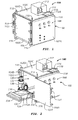
Figure 1 is an isometric-view drawing of a containment vessel shown with its door in a closed position in accordance with one or more embodiments of the present disclosure. -
Figure 2 is an isometric-view drawing of the containment vessel ofFigure 1 shown with its door in a fully-open position in accordance with one or more embodiments of the present disclosure. -
Figure 3 is an isometric-view drawing of a containment vessel having a watertight membrane in accordance with one or more embodiments of the present disclosure. - Embodiments disclosed herein relate to assemblies and methods to contain test specimens during a pressure test using a portable containment vessel. As such, embodiments disclosed herein relate to a ballistic outer enclosure having a plurality of walls, a door, and a lock attached to a moveable base skid. Additionally, embodiments further relate to a sample tray operable through a doorway of the ballistic enclosure between an extended position and a retracted position, wherein the sample tray is configured to support the test specimen. Additionally, embodiments further relate to a manifold assembly to apply a pressurized test fluid to the test specimen, a containment fluid to surround the test specimen while pressurized, and a sensor to indicate escape of the pressurized test fluid from the test specimen. Additionally still, embodiments further relate to a fluid-tight membrane positioned within the ballistic outer enclosure to retain the containment fluid.
- Referring initially to
Figure 1 , aportable containment vessel 100 in accordance with embodiments of the present disclosure is shown.Portable containment vessel 100 includes an ballisticouter enclosure 102 having a plurality ofwalls door 102F operable between a closed position (shown) and one or more open positions (e.g.,Figures 2 and3 ). Alock mechanism 104 is shown to securedoor 102F to a location adjacent to leftside wall 102D, and ahinge apparatus 106 allowsdoor 102F to rotate between closed and open positions. Whiledoor 102F is shown inFigures 1-3 as a hinge-type door rotating about an axis ofhinges 106, it should be understood by those having ordinary skill thatdoor 102F may be any type door known in the art including, but not limited to, sliding doors, roll-up doors, folding doors, and/or other types of rotating (hinged or otherwise) doors. - With
door 102F ofcontainment vessel 100 closed, amanifold assembly 108 may be used to supply high-pressure test fluid throughhigh pressure lines 110 to a test specimen (e.g., 128 ofFigure 2 ) contained withinwalls 102A-102E anddoor 102F ofcontainment vessel 100. As would be understood by those having ordinary skill,manifold assembly 108 may include any combination of gauges and valves known in the art to direct the high-pressure test fluid to a volume to be tested within test specimen (e.g., 128 ofFigure 2 ) contained withinvessel 100. - Additionally,
containment vessel 100 may also include a low-pressure fill pump 112 to direct a containment fluid throughfluid supply line 114 and into the volume of containment vessel generally defined bywalls 102A-102E anddoor 102F. Finally, as shown in the embodiment disclosed inFigure 1 ,containment vessel 100 may additionally include handling features in the form offorklift legs 116 and lifting pad-eyes 118 to facilitate the lifting, movement, and placement ofcontainment vessel 100 to a desired location by an overhead crane, a forklift, or other material-handling machine. Alternatively still,containment vessel 100 may include one or more casters or wheels (not shown) to assist in maneuvering it from one location to another without the assistance of a material-handling machine. As such, a person having ordinary skill in the art of material handling and/or oilfield technology would understand the term "skid" to appropriately describe construction and arrangement of handling features (e.g.,forklift legs 116 and lifting pad-eyes 118) integrated withcontainment vessel 100 in that the term is frequently used to describe a piece of equipment having a unitized structure that is configured for easy manipulation and movement by commonly-found industrial handling machines. - Referring now to
Figure 2 ,containment vessel 100 ofFigure 1 is shown withdoor 102F in a fully-open position, allowing full access to aninterior volume 120 through adoorway 122 defined generally bywalls 102A-102E such that when closed,doorway 122 is blocked bydoor 102F (as shown inFigure 1 ). Asample tray 124, shown inFigure 2 in a fully extended position, provides awork surface 126 upon which atest specimen 128 may be placed prior to retractingsample tray 124 intointerior volume 120 ofcontainment vessel 100. - As shown,
sample tray 124 andwork surface 126 may be fully retracted within, or fully extended frominterior volume 120 of containment vessel. In one or more embodiments,sample tray 124 may retract and extend into and frominterior volume 120 upon roller bearings, friction slides, or any other linear or non-linear material handling mechanism known to those having ordinary skill in the art. Additionally, movement ofsample tray 124 may be displaced manually (e.g., by an operator) between retracted and extended positions or with the assistance of powered mechanisms (not shown) including, but not limited to, hydraulic rams, pneumatic rams, electric motors, linear thrusters, and the like. In one or more embodiments,sample tray 124 may not fully extend frominterior volume 120 ofcontainment vessel 100, and in other embodiments,sample tray 124 may extend beyond "full" extension frominterior volume 120. - With
sample tray 124 extended as shown inFigure 2 , a crane, forklift, or other lifting or material-handling machine may have full access (overhead, from the front, and from one or more sides) towork surface 126 such thattest specimen 128 may be positioned thereupon without interference fromwalls 102A-102E,door 102F, or any other component ofcontainment vessel 100. As shown inFigure 2 ,test specimen 128 may comprise abase plate 130 and one ormore forklift legs 132, to facilitate loading oftest specimen 128 ontowork surface 126. Withtest specimen 128 positioned uponwork surface 126 ofsample tray 124, an operator is able to connect internalhigh pressure lines 110A that are in fluid communication with externalhigh pressure lines 110 andmanifold assembly 108 to pressure test fittings (not shown) on test specimen. As would be understood by those having ordinary skill, pressure test fittings allow communication of test fluid frommanifold assembly 108 to communicate with and pressurize a test volume (not shown) withintest specimen 128 throughhigh pressure lines - With
test specimen 128 positioned uponwork surface 126 ofsample tray 124 andhigh pressure lines 110A connected to the satisfaction of the operator overseeing the pressure test ofspecimen 128,sample tray 124 may be retracted (either manually or with mechanical assistance) back intointerior volume 120 ofcontainment vessel 100 so thatdoor 102F may be closed. As shown,door 102F may include ahandle 134 and afirst component 104A of lock mechanism 104 (Figure 1 ) to engage asecond component 104B oflock mechanism 104 proximal toside wall 102D ofouter enclosure 102. Withdoor 102F closed behind retractedsample tray 124,components lock 104 may be engaged to securely enclosetest specimen 128 withininterior volume 120 ofcontainment vessel 100. - With
test specimen 128 connected tohigh pressure lines door 102F secured and locked bymechanism 104,internal volume 120 ofcontainment vessel 100 may be filled with a containmentfluid using pump 112 andsupply line 114. Alternatively, should no pump 112 be installed tocontainment vessel 100, containment fluid may be manually added to interior volume ofclosed containment vessel 100 through a port (not shown) located on the exterior of ballisticouter enclosure 102. - As used herein, the term "ballistic" in reference to
outer enclosure 102 refers to the ability of walls (102A-102E) anddoor 102F ofenclosure 102 to retard, retain, or otherwise constrain an accelerated mass from withinenclosure 102 that might otherwise tend to penetrateouter enclosure 102, potentially causing damage to nearby equipment, workers, or thecontainment vessel 100 itself. As would be understood by those having ordinary skill, the amount of ballistic ability desired forwalls 102A-102E anddoor 102F ofouter enclosure 102 may depend on the type, configuration, and size oftest specimen 128 to be tested as well as the type and pressure of the test fluid to be applied bymanifold assembly 108 and high pressure lines 110. - For example, an incompressible test fluid (e.g., water, glycol, drilling mud, etc.) applied to an internal test volume of
test specimen 128 may require less ballistic protection fromouter enclosure 102 than a compressible test fluid (e.g., air, nitrogen gas, etc.) applied to thesame test specimen 128 being tested at the same test pressure. As known to those skilled in the art, pressurized compressible fluids (e.g., gasses) exhibit much more rapid expansion (i.e., release of potential energy through kinetic energy) upon their release than do their incompressible counterparts. While those having ordinary skill will appreciate that it may be "safer" to only pressure test a specimen (e.g., test specimen 128) using an incompressible medium, the design and function of the specimen (e.g., those having internal electronic components) may require a "dry" test be performed by an inert or otherwise non-reactive medium such as compressible nitrogen gas. - Additionally, depending on the amount of test pressure to be applied to test fluid through
lines 110 connected to test volume oftest specimen 128, the thickness, material, geometry, and construction ofwalls 102A-102E anddoor 102F may be varied to maximize the amount of kinetic energy containable withinouter enclosure 102 when used in conjunction with a given containment fluid at a specified test pressure. For example,walls 102A-102E anddoor 102F may be constructed of various forms of steel (e.g., cast, forged, cold worked, etc.), aluminum, tungsten, Kevlar, carbon-fiber composite, or any other material known in the art. - Additionally the
walls 102A-102E anddoor 102F ofouter enclosure 102 may be constructed as single-thickness "plates" of a single material or as a multi-laminated "sandwich" of one or more different materials to increase ballistic strength and/or reduce the overall weight ofcontainment vessel 100. For example, tests have shown that a ballistic wall panel (e.g. 102A-102F) constructed of ten plies of 2 mm steel may have a increased ballistic resistance relative to a ballistic wall panel constructed of a single 2 cm steel panel for a giventest specimen 128 at a specified test pressure. Moreover, constructing such a laminated panel with layers of carbon-fiber composite or Kevlar interleaved between adjacent plies of steel may have the benefit of greatly increasing ballistic resistance while only minimally increasing the overall weight and/or thickness of the panel. - In alternative embodiments,
walls 102A-102E anddoor 102F may be constructed of lightweight, relatively inexpensive and easily replaceable "sacrificial" materials (e.g., carbon fiber composite or Kevlar) held into place by a high strength rigid space frame to contain releases of potential energy fromtest specimen 128 withininterior volume 120. Thus, in the event of a sudden pressure release fromtest specimen 128, only the affected or otherwise damaged wall panels (102A-102F) may be replaced rather than requiring shipping and repair of theentire containment vessel 100 assembly. Alternatively still, panels of eachwall 102A-102E anddoor 102F may be constructed from different materials should anisotropic containment of aparticular test specimen 128 be desired or otherwise advantageous for a particular test. Alternatively still,outer enclosure 102 may be constructed such thatcontainment vessel assembly 100 can be assembled surrounding aparticular test specimen 128 while in use so that an in-situ pressure test ofspecimen 128 may be performed. - Referring now to
Figure 3 , acontainment vessel 200 in accordance with one or more alternative embodiments of the present disclosure is shown.Containment vessel 200 is similar tocontainment vessel 100 ofFigures 1-2 , with the exception thatcontainment vessel 200 additionally includes one or more fluid-tight membranes 240F separating walls 202A-202E anddoor 202F ofouter enclosure 202 frominterior volume 220 ofcontainment vessel 200. While only fluid-tight membranes door 202F are visible inFigure 3 , it should be understood that additional fluid-tight membranes (i.e., 240A, 240B, 240C, and 240E) corresponding towalls - As would be understood by those having ordinary skill in the art, fluid-tight membranes (referred to as 240, generally) may comprise any substantially flexible material capable of containing fluids within
interior volume 220 ofcontainment vessel 200 including, but not limited to PVC, silicone, polyethylene, and/or other similar elastomers and polymers. Additionally, depending on configuration and preference, fluid tight-membranes 240 may be located adjacent to one ormore walls 202A-202E,door 202F, or any combination thereof. As such, fluid-tight membranes may be used to isolate or protect interior components (e.g.,manifold assembly 108 ofFigures 1-2 ) from containment fluids, or may be used to retain containment fluids withininterior volume 220 withdoor 202F partially or fully open (as shown inFigure 3 ). - In one or more embodiments, fluid-tight membranes may be constructed as transparent, semi-transparent, partially opaque, or fully opaque so that the
internal volume 220 ofcontainment vessel 200 may be viewable through membranes 240, if desired. Thus, an operator may enclose a test specimen (e.g., 128) withininterior volume 220 ofvessel 200, secure fluid-tight membranes 240 closed, and observe and monitortest specimen 128 during the early phase of a pressure test to determine if leaks of test fluid are occurring at such low pressures. When pressure of test fluid is increased, the operator may then close and lockdoor 202F to engage the full ballistic integrity ofouter enclosure 202. - Additionally, in one or more embodiments, fluid-
tight membrane 240F adjacent todoorway 222 ofcontainment vessel 200 may be constructed in a retractable or otherwise quickly and easily removable (e.g., through automated and computer controlled cylinders, servos, etc.) configuration. For example, in one or more embodiments, fluidtight membrane 240F may be retractable into a recess or pocket located adjacent to a lower, upper, right, or left side end ofdoorway 222. In one or more embodiments, one or more mechanical fasteners may assist in maintaining a fluid-tight seal betweenmembrane 240F and upper, lower, right, and/or left side ends ofdoorway 222. As would be understood by those having ordinary skill, such fasteners may include, but should not be limited to, magnets, hooks, snaps, zippers, and the like. In one or more alternative embodiments, operation (e.g., retraction and extension) of fluid-tight membranes may be automated by one or more mechanical devices. - Referring generally to
Figures 1-3 together, the use ofcontainment vessels containment vessels containment vessels containment vessels - Upon location at the worksite, the
locking mechanism 104 may be unlatched, thedoor sample tray 124 extended from theinternal volume outer enclosure Figure 2 ) may be placed uponwork surface 126. At this time, an operator may proceed to connect internal high-pressure fluid lines 110A to testspecimen 128 such that the testing fluid will be in communication with a volume to be tested withintest specimen 128. Once connected,sample tray 124 may be retracted either manually or through an aforementioned method of mechanical assistance, fluid-tight membrane 240F (if present) blockingdoorway door locking mechanism 104 engaged. - Once
door containment vessel pressure fill pump 112 and fluid supply line 114) or otherwise poured into theinternal volume test specimen 128 and bounded bywalls 102A-102F, 202A-202F and/or fluid-tight membranes 240A-240F (if present) until a desired amount of containment fluid surroundstest specimen 128. In one or more alternative embodiments, the containment fluid may comprise a gas (e.g., air) that may either be pumped into or may already be present withincontainment vessel test specimen 128 through high-pressure lines manifold assembly 108 at a selected pressure desired for the pressure test. - Alternatively, in embodiments where fluid-tight membranes 240 are present, the operator may fill the
internal volume 220 with containment fluid prior to closing and lockingdoor 202F, so that test fluid may be supplied to test volume oftest specimen 128 at an initial, reduced pressure to ensure that connections betweentest specimen 128,lines manifold assembly 108 have been correctly made. Once connection integrity ofhigh pressure lines manifold assembly 108 to testspecimen 128 has been confirmed, the operator may then close and lockdoor 202F before proceeding with pressure testing at elevated pressures. Additionally, in one or more embodiments, testing operations may be performed autonomously using a control system so that thetest specimen 128 andhigh pressure lines - As would be understood by those having ordinary skill in the art, the containment fluid used with embodiments disclosed herein may comprise any fluid (i.e., liquid, gas, gel, or a combination thereof) exhibiting ballistic qualities in reducing the kinetic energy of masses in the aftermath of a sudden (e.g., explosive) release of potential energy. As such, various fluid characteristics including, but not limited to fluid compressibility, density (or specific gravity), corrosivity, pH, surface tension, viscosity, and the like may be specified in determining a desirable candidate for containment fluid. However, as
containment vessels - Additionally, as would be understood by those having ordinary skill in the art, the test fluid used with embodiments disclosed herein may comprise any fluid (i.e., liquid, gas, gel, or combination thereof) known to be useful in performing pressure tests to test volumes. Similarly to containment fluid described above, test fluid may be selected based upon a variety of fluid characteristics including, but not limited to compressibility, density, corrosivity, pH, surface tension, viscosity, and may be selected from fluids readably available at the test site. As would be understood by those having ordinary skill, test fluids may be selected and used to test specimens (e.g., 128) up to and in excess of 135 MPa (20 ksi) for compressible testing fluids and up to and in excess of 200 MPa (30 ksi) for incompressible testing fluids.
- Additionally, in one or more embodiments, candidates for containment and test fluids may be evaluated and selected based upon their abilities to indicate the presence of leaks or other test volume failures within the
internal volume outer enclosures test specimen 128 occur. Alternatively, should a liquid be desired for test fluid, a dye may be included with test fluid such that a color change in containment fluid would be visible should test fluid leak fromtest specimen 128. Alternatively still, an operator may closely monitor a gauge (not shown) ofmanifold assembly 108, so that an internal failure (i.e., a failure where the leaking test fluid is contained within test specimen 128) of test volume may be detected by observing a sudden drop in pressure of the test fluid. - Additionally, one or more sensing devices including, but not limited to, flow sensors, transducers, and gas leak detectors, (not shown) may be installed within
internal volume containment vessels internal volume internal volume internal volume containment vessels test specimen 128 as the test is being performed. Finally, in order to accommodate circumstances where a test specimen (e.g., 128) is to be placed into high-temperature and high-pressure (HTHP) service, one or more heating elements (not shown) may be placed withininternal volume containment vessels - Advantageously, embodiments disclosed herein allow a test specimen to be safely pressure tested in remote locations, locations that can be several travel days removed from the closest traditional pressure test facility. As such, embodiments disclosed herein allow operators to safely perform verification testing on-site (and with various combinations of test and containment fluids) thereby allowing various operations such as modification, assembly, and refurbishment of components shortly before, during, and after they are deployed to remote or field locations. As such, defective components may be identified and repaired locally before they are placed in service, as opposed to after when such repair would be more inconvenient, time consuming, expensive, and difficult.
- Advantageously still, embodiments disclosed herein allow for the application of different mediums (e.g., water and/or Nitrogen gas) to an inner volume of a test article without having to change or disturb the supply and/or vent high pressure lines to the test article between testing operations. Additionally, embodiments disclosed herein may allow an automatic sequence of testing the specimen first with a non-compressible test fluid at a first pressure to verify pressure integrity, followed by the filling of the ballistic enclosure with a containment fluid medium and a subsequent testing of test article with a compressible (e.g., a gas) test fluid at a second pressure. In one or more embodiments, the first pressure test may verify pressure integrity through detection of a stable pressure within the test specimen (e.g., monitored with a pressure sensor) while the second pressure test may verify sealing integrity through the observance of bubbles (using a camera or other sensor) escaping the test specimen into the containment fluid. In one or more embodiments, the apparatus may be automated such that the test specimen may be tested without requiring disturbance of the test specimen or high pressure lines between subsequent test operations.
- While the disclosure has been presented with respect to a limited number of embodiments, those skilled in the art, having benefit of this disclosure, will appreciate that other embodiments may be devised which do not depart from the scope of the present disclosure. Accordingly, the scope of the invention should be limited only by the attached claims, although additional combinations of independent and dependent claims beyond those specifically recited below are fully contemplated by the inventors and supported by the specification above.
Claims (20)
- A portable containment vessel (100; 200) to perform a pressure test to a test specimen (128), the portable containment vessel (100; 200) comprising:an optional base skid (116, 118);a ballistic outer enclosure (102; 202) connected to the optional base skid (116, 118) and comprising a plurality of walls (102A-102E; 202A-202E), a door (102F; 202F), and a lock (104) to maintain the door (102F; 202F) in a closed position;a sample tray (124) configured to support the test specimen (128), wherein the sample tray (124) is operable through a doorway (122; 222) of the ballistic outer enclosure (102; 202) between a retracted position and an extended position;a containment fluid to surround the test specimen (128) while a pressurized fluid is applied to the test specimen (128); anda sensor to indicate a failure of the pressure test.
- The portable containment vessel (100; 200) of claim 1, further comprising at least one fluid tight membrane (240A-240F) positioned within the ballistic outer enclosure (202).
- The portable containment vessel (100; 200) of claim 2, wherein a fluid tight membrane (240F) positioned adjacent to the door (202F) of the ballistic outer enclosure (202) is retractable to allow access to an interior volume (220) when the door (202F) is in an open position.
- The portable containment vessel (100; 200) of any one of claims 1-3, further comprising a manifold assembly (108) to selectively apply the pressurized test fluid to the test specimen (128).
- The portable containment vessel (100; 200) of any one of claims 1-4, wherein the sensor comprises a camera.
- The portable containment vessel (100; 200) of any one of claims 1-4, wherein the sensor comprises a pressure gauge.
- The portable containment vessel (100; 200) of any one of claims 1-6, wherein the sensor is configured to detect a presence of the test fluid in the containment liquid.
- The portable containment vessel (100; 200) of any one of claims 1-7, wherein the containment fluid comprises water.
- The portable containment vessel (100; 200) of any one of claims 1-7, wherein the containment fluid comprises drilling mud.
- The portable containment vessel (100; 200) of any one of claims 1-7, wherein the containment fluid comprises a gas.
- The portable containment vessel (100; 200) of any one of claims 1-10, further comprising a pump (112) to supply the containment fluid to an interior volume (120) of the ballistic outer enclosure (102).
- The portable containment vessel (100; 200) of any one of claims 1-11, further comprising a heater to increase the temperature of the test specimen (128).
- A method to test the internal pressure integrity of a test specimen (128), the method comprising:positioning the test specimen (128) inside a ballistic outer enclosure (102; 202);connecting the test specimen (128) to a test fluid supply;sealing the test specimen (128) within the ballistic enclosure (102; 202);filling the ballistic enclosure (102; 202) with a containment fluid;increasing a pressure of the test fluid supply to a desired test pressure; andmonitoring the test specimen (128) to determine its internal pressure integrity.
- The method of claim 13, further comprising positioning the test specimen (128) inside the ballistic outer enclosure (102; 202) with an extendable sample tray (124).
- The method of claim 13 or claim 14, further comprising sealing the test specimen (128) within the ballistic outer enclosure (102; 202) with at least one fluid-tight membrane (240A-240F).
- The method of any one of claims 13-15, further comprising monitoring the test specimen (128) through the fluid-tight membrane (240A-240F) while a door (102F; 202F) of the ballistic outer enclosure (102; 202) is open.
- The method of any one of claims 13-16, further comprising monitoring the test specimen (128) with a camera.
- The method of any one of claims 13-16, further comprising monitoring the test specimen (128) with a sensor configured to detect the presence of the test fluid in the containment fluid.
- The method of any one of claims 13-18, further comprising heating the test specimen (128).
- The method of any one of claims 13-19, further comprising:testing the test specimen (128) at a first test pressure using a first test fluid supply and a first containment fluid; andtesting the test specimen (128) at a second test pressure using a second test fluid supply and a second containment fluid.
Applications Claiming Priority (1)
| Application Number | Priority Date | Filing Date | Title |
|---|---|---|---|
| US13/886,947 US9612181B2 (en) | 2013-05-03 | 2013-05-03 | Pressure test containment vessel |
Publications (3)
| Publication Number | Publication Date |
|---|---|
| EP2799837A2 true EP2799837A2 (en) | 2014-11-05 |
| EP2799837A3 EP2799837A3 (en) | 2015-04-15 |
| EP2799837B1 EP2799837B1 (en) | 2018-07-04 |
Family
ID=50679885
Family Applications (1)
| Application Number | Title | Priority Date | Filing Date |
|---|---|---|---|
| EP14167040.6A Active EP2799837B1 (en) | 2013-05-03 | 2014-05-05 | Pressure test containment vessel |
Country Status (5)
| Country | Link |
|---|---|
| US (1) | US9612181B2 (en) |
| EP (1) | EP2799837B1 (en) |
| AU (1) | AU2014202354B2 (en) |
| BR (1) | BR102014010488B8 (en) |
| SG (1) | SG10201402022TA (en) |
Cited By (2)
| Publication number | Priority date | Publication date | Assignee | Title |
|---|---|---|---|---|
| CN105806600A (en) * | 2016-03-10 | 2016-07-27 | 中国北方车辆研究所 | Hydro-pneumatic spring testbed position hydraulic adjustment device with locking function |
| CN106525111A (en) * | 2016-10-14 | 2017-03-22 | 歌尔股份有限公司 | Pressure calibration device |
Families Citing this family (10)
| Publication number | Priority date | Publication date | Assignee | Title |
|---|---|---|---|---|
| US20150136422A1 (en) * | 2013-11-18 | 2015-05-21 | Rodgers Technology, Llc | Apparatus and method for deploying equipment into a wellbore |
| CN106153332A (en) * | 2016-09-23 | 2016-11-23 | 江西洪都航空工业集团有限责任公司 | A kind of ball cover structure pressurising test fixture |
| CN109682582B (en) * | 2018-10-31 | 2021-03-30 | 安徽江淮汽车集团股份有限公司 | Lock reliability test device |
| US20240142333A1 (en) * | 2020-06-30 | 2024-05-02 | Fermi Research Alliance, Llc | Portable Self-Contained Pressure Testing Manifold and Associated Methods |
| US11906479B2 (en) * | 2020-06-30 | 2024-02-20 | Fermi Research Alliance, Llc | Portable self-contained pressure testing manifold and associated methods |
| CN113049393B (en) * | 2021-03-17 | 2023-06-13 | 重庆蓝散科技有限公司 | Plate pressure detection device capable of being uniformly pressed for deep sea detection |
| US20240110856A1 (en) * | 2022-09-30 | 2024-04-04 | Saudi Arabian Oil Company | Wireless sensors for monitoring fluid quality, pressure and temperature |
| CN117087953B (en) * | 2023-08-30 | 2025-08-15 | 石家庄格瑞药业有限公司 | Vacuum leak detector |
| US20250164367A1 (en) * | 2023-11-22 | 2025-05-22 | The Boeing Company | Systems and methods for material testing and material testpieces |
| CN120405164B (en) * | 2025-06-12 | 2025-09-19 | 武汉克莱美特创新技术有限公司 | Material and component performance test method based on remote monitoring |
Family Cites Families (24)
| Publication number | Priority date | Publication date | Assignee | Title |
|---|---|---|---|---|
| NL91317C (en) | 1958-08-07 | 1959-06-15 | ||
| GB1260022A (en) | 1968-11-04 | 1972-01-12 | Bridgestone Liquefied Gas Co | A method of testing a membrane tank |
| US3958448A (en) * | 1974-10-10 | 1976-05-25 | Aluminum Company Of America | Test apparatus for pressurized container and method |
| US3955402A (en) * | 1975-09-22 | 1976-05-11 | The Coca-Cola Co. | Pass level tester for glass bottles |
| US4089208A (en) | 1977-01-07 | 1978-05-16 | Owens-Illinois, Inc. | Pressure test fixture for pressurized containers |
| JPS5726044U (en) * | 1980-07-19 | 1982-02-10 | ||
| US4523454A (en) | 1983-10-21 | 1985-06-18 | Sharp Bruce R | External jacket system as secondary containment for storage tanks |
| US4977418A (en) * | 1989-10-03 | 1990-12-11 | Canty Thomas M | Camera viewing unit |
| US5057171A (en) | 1990-04-26 | 1991-10-15 | Pacific Trinetics Corporation | Isostatic press for laminating multi-layer components and method of lamination |
| US5123278A (en) * | 1991-02-19 | 1992-06-23 | Ball Corporation | Pressure tester and method |
| US5220824A (en) * | 1991-08-20 | 1993-06-22 | The Pennsylvania Research Corporation | High temperature, tube burst test apparatus |
| US5834630A (en) | 1997-02-19 | 1998-11-10 | Tanaka Scientific Limited | Apparatus for measuring flash point of article |
| US6082182A (en) | 1997-10-20 | 2000-07-04 | Vista Research, Inc. | Apparatus for measuring the flow rate due to a leak in a pressurized pipe system |
| US6253599B1 (en) * | 1999-06-03 | 2001-07-03 | The Aerospace Corporation | Pressure vessel testing fixture |
| US6722184B2 (en) | 2001-09-13 | 2004-04-20 | Guide Corporation | Apparatus and method for pressurized oxygen bulb curing and testing |
| US6619104B1 (en) * | 2002-06-12 | 2003-09-16 | Kuo Toon International Co., Ltd. | Continuous testing device for water pipe |
| US20060102015A1 (en) | 2004-11-12 | 2006-05-18 | Bsh Home Appliances Corporation | Retractable oven rack assembly |
| FR2882823B1 (en) | 2005-03-04 | 2007-05-11 | Vallourec Mannesmann Oil Gas F | INSTALLATION AND METHOD FOR MECHANICAL SAMPLE SOLICITATION USING A PACKER |
| DE102006001425B4 (en) * | 2006-01-10 | 2009-10-01 | Benteler Automobiltechnik Gmbh | Rohrprüfanlage |
| US8146428B2 (en) * | 2008-08-08 | 2012-04-03 | Lavergne Terry J | Safety system |
| US8453515B2 (en) * | 2010-09-03 | 2013-06-04 | UT-BaHelle, LLC | Apparatus and method for fatigue testing of a material specimen in a high-pressure fluid environment |
| CN201955205U (en) | 2010-12-20 | 2011-08-31 | 浙江豪情汽车制造有限公司 | Device for detecting sealing performance of automobile parts |
| CN202305339U (en) | 2011-10-19 | 2012-07-04 | 肇庆市洪利电子科技有限公司 | Explosion-proof pressure test device for air pressure on capacitor case |
| JP5642121B2 (en) | 2012-07-19 | 2014-12-17 | 三菱電機株式会社 | Air conditioner |
-
2013
- 2013-05-03 US US13/886,947 patent/US9612181B2/en active Active
-
2014
- 2014-04-30 BR BR102014010488A patent/BR102014010488B8/en active IP Right Grant
- 2014-04-30 AU AU2014202354A patent/AU2014202354B2/en active Active
- 2014-05-02 SG SG10201402022TA patent/SG10201402022TA/en unknown
- 2014-05-05 EP EP14167040.6A patent/EP2799837B1/en active Active
Non-Patent Citations (1)
| Title |
|---|
| None |
Cited By (4)
| Publication number | Priority date | Publication date | Assignee | Title |
|---|---|---|---|---|
| CN105806600A (en) * | 2016-03-10 | 2016-07-27 | 中国北方车辆研究所 | Hydro-pneumatic spring testbed position hydraulic adjustment device with locking function |
| CN105806600B (en) * | 2016-03-10 | 2017-12-12 | 中国北方车辆研究所 | A kind of hydro-pneumatic spring bed stead hydraulic adjustment device with blocking function |
| CN106525111A (en) * | 2016-10-14 | 2017-03-22 | 歌尔股份有限公司 | Pressure calibration device |
| CN106525111B (en) * | 2016-10-14 | 2019-08-16 | 歌尔股份有限公司 | Pressure calibration device |
Also Published As
| Publication number | Publication date |
|---|---|
| BR102014010488B8 (en) | 2021-05-25 |
| EP2799837A3 (en) | 2015-04-15 |
| US9612181B2 (en) | 2017-04-04 |
| EP2799837B1 (en) | 2018-07-04 |
| AU2014202354B2 (en) | 2016-07-21 |
| BR102014010488B1 (en) | 2020-11-10 |
| US20140326050A1 (en) | 2014-11-06 |
| AU2014202354A1 (en) | 2014-11-20 |
| SG10201402022TA (en) | 2014-12-30 |
| BR102014010488A2 (en) | 2015-12-29 |
Similar Documents
| Publication | Publication Date | Title |
|---|---|---|
| EP2799837B1 (en) | Pressure test containment vessel | |
| US8191430B2 (en) | Method and apparatus for pipe testing | |
| US8731849B2 (en) | Hydrostatic pressure testing system and method | |
| CN109342177B (en) | Full-size pipeline deep sea complex marine environment load combined loading test system | |
| US6435279B1 (en) | Method and apparatus for sampling fluids from a wellbore | |
| US9570224B2 (en) | Pressure compensation system | |
| US20160084031A1 (en) | Multi-stage blowout preventer and method of using same | |
| CN106197870A (en) | A kind of immersion detection system and method | |
| US20170055356A1 (en) | Pressure compensator failure detection | |
| Kaur et al. | Development of a robot for in-service radiography inspection of subsea flexible risers | |
| KR101644126B1 (en) | Apparatus for testing barrier leakage of LNG tank | |
| JP5522685B2 (en) | Sealing device | |
| EP3021101A1 (en) | Apparatus and method for monitoring of hollow engineering structures | |
| Bruce et al. | Physical testing method to study ice keel strength limits during a gouging process | |
| KR20150063752A (en) | Pressure Vessel and Test Apparatus for Drilling Equipment Using The Same | |
| CN118883248A (en) | A physical simulation experimental system for gas-liquid multiphase seepage in gas reservoir type gas storage | |
| Bauer et al. | Helium-Mass-Spectrometry-Permeameter for the measurement of permeability of low permeability rock with application to triaxial deformation conditions | |
| CN117054073A (en) | Industrial valve pressure detection system | |
| Hauge et al. | Deepwater horizon: Lessons learned for the norwegian petroleum industry with focus on technical aspects | |
| CN206019952U (en) | A kind of watertightness test device | |
| US20180031440A1 (en) | Bop test apparatus | |
| Hernández-Rojo et al. | Experimental and numerical analysis of failure in flexible pipe by a mechanism of intentional damage | |
| WO2025191243A1 (en) | Alert system for a subsea infrastructure | |
| KR102075969B1 (en) | BOP Test Control System | |
| KR20140137275A (en) | Test Apparatus for Drilling Equipment |
Legal Events
| Date | Code | Title | Description |
|---|---|---|---|
| PUAI | Public reference made under article 153(3) epc to a published international application that has entered the european phase |
Free format text: ORIGINAL CODE: 0009012 |
|
| 17P | Request for examination filed |
Effective date: 20140505 |
|
| AK | Designated contracting states |
Kind code of ref document: A2 Designated state(s): AL AT BE BG CH CY CZ DE DK EE ES FI FR GB GR HR HU IE IS IT LI LT LU LV MC MK MT NL NO PL PT RO RS SE SI SK SM TR |
|
| AX | Request for extension of the european patent |
Extension state: BA ME |
|
| PUAL | Search report despatched |
Free format text: ORIGINAL CODE: 0009013 |
|
| RIC1 | Information provided on ipc code assigned before grant |
Ipc: G01M 3/26 20060101ALI20150210BHEP Ipc: G01M 3/06 20060101ALI20150210BHEP Ipc: G01M 3/04 20060101ALI20150210BHEP Ipc: G01M 3/32 20060101ALI20150210BHEP Ipc: G01N 3/12 20060101AFI20150210BHEP Ipc: G01M 3/02 20060101ALI20150210BHEP |
|
| RIC1 | Information provided on ipc code assigned before grant |
Ipc: G01M 3/26 20060101ALI20150220BHEP Ipc: G01M 3/32 20060101ALI20150220BHEP Ipc: G01M 3/06 20060101ALI20150220BHEP Ipc: G01N 3/12 20060101AFI20150220BHEP Ipc: G01M 3/04 20060101ALI20150220BHEP Ipc: G01M 3/02 20060101ALI20150220BHEP |
|
| RIC1 | Information provided on ipc code assigned before grant |
Ipc: G01M 3/02 20060101ALI20150227BHEP Ipc: G01M 3/26 20060101ALI20150227BHEP Ipc: G01M 3/32 20060101ALI20150227BHEP Ipc: G01M 3/06 20060101ALI20150227BHEP Ipc: G01M 3/04 20060101ALI20150227BHEP Ipc: G01N 3/12 20060101AFI20150227BHEP |
|
| AK | Designated contracting states |
Kind code of ref document: A3 Designated state(s): AL AT BE BG CH CY CZ DE DK EE ES FI FR GB GR HR HU IE IS IT LI LT LU LV MC MK MT NL NO PL PT RO RS SE SI SK SM TR |
|
| AX | Request for extension of the european patent |
Extension state: BA ME |
|
| RIC1 | Information provided on ipc code assigned before grant |
Ipc: G01N 3/12 20060101AFI20150306BHEP Ipc: G01M 3/02 20060101ALI20150306BHEP Ipc: G01M 3/26 20060101ALI20150306BHEP Ipc: G01M 3/04 20060101ALI20150306BHEP Ipc: G01M 3/06 20060101ALI20150306BHEP Ipc: G01M 3/32 20060101ALI20150306BHEP |
|
| R17P | Request for examination filed (corrected) |
Effective date: 20151006 |
|
| RBV | Designated contracting states (corrected) |
Designated state(s): AL AT BE BG CH CY CZ DE DK EE ES FI FR GB GR HR HU IE IS IT LI LT LU LV MC MK MT NL NO PL PT RO RS SE SI SK SM TR |
|
| STAA | Information on the status of an ep patent application or granted ep patent |
Free format text: STATUS: EXAMINATION IS IN PROGRESS |
|
| 17Q | First examination report despatched |
Effective date: 20170727 |
|
| GRAP | Despatch of communication of intention to grant a patent |
Free format text: ORIGINAL CODE: EPIDOSNIGR1 |
|
| STAA | Information on the status of an ep patent application or granted ep patent |
Free format text: STATUS: GRANT OF PATENT IS INTENDED |
|
| INTG | Intention to grant announced |
Effective date: 20180110 |
|
| GRAS | Grant fee paid |
Free format text: ORIGINAL CODE: EPIDOSNIGR3 |
|
| GRAA | (expected) grant |
Free format text: ORIGINAL CODE: 0009210 |
|
| STAA | Information on the status of an ep patent application or granted ep patent |
Free format text: STATUS: THE PATENT HAS BEEN GRANTED |
|
| AK | Designated contracting states |
Kind code of ref document: B1 Designated state(s): AL AT BE BG CH CY CZ DE DK EE ES FI FR GB GR HR HU IE IS IT LI LT LU LV MC MK MT NL NO PL PT RO RS SE SI SK SM TR |
|
| REG | Reference to a national code |
Ref country code: GB Ref legal event code: FG4D |
|
| REG | Reference to a national code |
Ref country code: CH Ref legal event code: EP |
|
| REG | Reference to a national code |
Ref country code: AT Ref legal event code: REF Ref document number: 1015039 Country of ref document: AT Kind code of ref document: T Effective date: 20180715 |
|
| REG | Reference to a national code |
Ref country code: IE Ref legal event code: FG4D |
|
| REG | Reference to a national code |
Ref country code: DE Ref legal event code: R096 Ref document number: 602014027764 Country of ref document: DE |
|
| RAP2 | Party data changed (patent owner data changed or rights of a patent transferred) |
Owner name: FMC TECHNOLOGIES, INC. |
|
| REG | Reference to a national code |
Ref country code: NL Ref legal event code: MP Effective date: 20180704 |
|
| REG | Reference to a national code |
Ref country code: NO Ref legal event code: T2 Effective date: 20180704 |
|
| REG | Reference to a national code |
Ref country code: LT Ref legal event code: MG4D |
|
| REG | Reference to a national code |
Ref country code: AT Ref legal event code: MK05 Ref document number: 1015039 Country of ref document: AT Kind code of ref document: T Effective date: 20180704 |
|
| PG25 | Lapsed in a contracting state [announced via postgrant information from national office to epo] |
Ref country code: NL Free format text: LAPSE BECAUSE OF FAILURE TO SUBMIT A TRANSLATION OF THE DESCRIPTION OR TO PAY THE FEE WITHIN THE PRESCRIBED TIME-LIMIT Effective date: 20180704 |
|
| PG25 | Lapsed in a contracting state [announced via postgrant information from national office to epo] |
Ref country code: CZ Free format text: LAPSE BECAUSE OF FAILURE TO SUBMIT A TRANSLATION OF THE DESCRIPTION OR TO PAY THE FEE WITHIN THE PRESCRIBED TIME-LIMIT Effective date: 20180704 Ref country code: BG Free format text: LAPSE BECAUSE OF FAILURE TO SUBMIT A TRANSLATION OF THE DESCRIPTION OR TO PAY THE FEE WITHIN THE PRESCRIBED TIME-LIMIT Effective date: 20181004 Ref country code: GR Free format text: LAPSE BECAUSE OF FAILURE TO SUBMIT A TRANSLATION OF THE DESCRIPTION OR TO PAY THE FEE WITHIN THE PRESCRIBED TIME-LIMIT Effective date: 20181005 Ref country code: IS Free format text: LAPSE BECAUSE OF FAILURE TO SUBMIT A TRANSLATION OF THE DESCRIPTION OR TO PAY THE FEE WITHIN THE PRESCRIBED TIME-LIMIT Effective date: 20181104 Ref country code: AT Free format text: LAPSE BECAUSE OF FAILURE TO SUBMIT A TRANSLATION OF THE DESCRIPTION OR TO PAY THE FEE WITHIN THE PRESCRIBED TIME-LIMIT Effective date: 20180704 Ref country code: FI Free format text: LAPSE BECAUSE OF FAILURE TO SUBMIT A TRANSLATION OF THE DESCRIPTION OR TO PAY THE FEE WITHIN THE PRESCRIBED TIME-LIMIT Effective date: 20180704 Ref country code: RS Free format text: LAPSE BECAUSE OF FAILURE TO SUBMIT A TRANSLATION OF THE DESCRIPTION OR TO PAY THE FEE WITHIN THE PRESCRIBED TIME-LIMIT Effective date: 20180704 Ref country code: LT Free format text: LAPSE BECAUSE OF FAILURE TO SUBMIT A TRANSLATION OF THE DESCRIPTION OR TO PAY THE FEE WITHIN THE PRESCRIBED TIME-LIMIT Effective date: 20180704 Ref country code: SE Free format text: LAPSE BECAUSE OF FAILURE TO SUBMIT A TRANSLATION OF THE DESCRIPTION OR TO PAY THE FEE WITHIN THE PRESCRIBED TIME-LIMIT Effective date: 20180704 Ref country code: PL Free format text: LAPSE BECAUSE OF FAILURE TO SUBMIT A TRANSLATION OF THE DESCRIPTION OR TO PAY THE FEE WITHIN THE PRESCRIBED TIME-LIMIT Effective date: 20180704 |
|
| PG25 | Lapsed in a contracting state [announced via postgrant information from national office to epo] |
Ref country code: AL Free format text: LAPSE BECAUSE OF FAILURE TO SUBMIT A TRANSLATION OF THE DESCRIPTION OR TO PAY THE FEE WITHIN THE PRESCRIBED TIME-LIMIT Effective date: 20180704 Ref country code: LV Free format text: LAPSE BECAUSE OF FAILURE TO SUBMIT A TRANSLATION OF THE DESCRIPTION OR TO PAY THE FEE WITHIN THE PRESCRIBED TIME-LIMIT Effective date: 20180704 Ref country code: HR Free format text: LAPSE BECAUSE OF FAILURE TO SUBMIT A TRANSLATION OF THE DESCRIPTION OR TO PAY THE FEE WITHIN THE PRESCRIBED TIME-LIMIT Effective date: 20180704 Ref country code: ES Free format text: LAPSE BECAUSE OF FAILURE TO SUBMIT A TRANSLATION OF THE DESCRIPTION OR TO PAY THE FEE WITHIN THE PRESCRIBED TIME-LIMIT Effective date: 20180704 |
|
| REG | Reference to a national code |
Ref country code: DE Ref legal event code: R097 Ref document number: 602014027764 Country of ref document: DE |
|
| PG25 | Lapsed in a contracting state [announced via postgrant information from national office to epo] |
Ref country code: EE Free format text: LAPSE BECAUSE OF FAILURE TO SUBMIT A TRANSLATION OF THE DESCRIPTION OR TO PAY THE FEE WITHIN THE PRESCRIBED TIME-LIMIT Effective date: 20180704 Ref country code: IT Free format text: LAPSE BECAUSE OF FAILURE TO SUBMIT A TRANSLATION OF THE DESCRIPTION OR TO PAY THE FEE WITHIN THE PRESCRIBED TIME-LIMIT Effective date: 20180704 Ref country code: RO Free format text: LAPSE BECAUSE OF FAILURE TO SUBMIT A TRANSLATION OF THE DESCRIPTION OR TO PAY THE FEE WITHIN THE PRESCRIBED TIME-LIMIT Effective date: 20180704 |
|
| PLBE | No opposition filed within time limit |
Free format text: ORIGINAL CODE: 0009261 |
|
| STAA | Information on the status of an ep patent application or granted ep patent |
Free format text: STATUS: NO OPPOSITION FILED WITHIN TIME LIMIT |
|
| PG25 | Lapsed in a contracting state [announced via postgrant information from national office to epo] |
Ref country code: SK Free format text: LAPSE BECAUSE OF FAILURE TO SUBMIT A TRANSLATION OF THE DESCRIPTION OR TO PAY THE FEE WITHIN THE PRESCRIBED TIME-LIMIT Effective date: 20180704 Ref country code: DK Free format text: LAPSE BECAUSE OF FAILURE TO SUBMIT A TRANSLATION OF THE DESCRIPTION OR TO PAY THE FEE WITHIN THE PRESCRIBED TIME-LIMIT Effective date: 20180704 Ref country code: SM Free format text: LAPSE BECAUSE OF FAILURE TO SUBMIT A TRANSLATION OF THE DESCRIPTION OR TO PAY THE FEE WITHIN THE PRESCRIBED TIME-LIMIT Effective date: 20180704 |
|
| 26N | No opposition filed |
Effective date: 20190405 |
|
| PG25 | Lapsed in a contracting state [announced via postgrant information from national office to epo] |
Ref country code: SI Free format text: LAPSE BECAUSE OF FAILURE TO SUBMIT A TRANSLATION OF THE DESCRIPTION OR TO PAY THE FEE WITHIN THE PRESCRIBED TIME-LIMIT Effective date: 20180704 |
|
| REG | Reference to a national code |
Ref country code: DE Ref legal event code: R119 Ref document number: 602014027764 Country of ref document: DE |
|
| REG | Reference to a national code |
Ref country code: CH Ref legal event code: PL |
|
| PG25 | Lapsed in a contracting state [announced via postgrant information from national office to epo] |
Ref country code: MC Free format text: LAPSE BECAUSE OF FAILURE TO SUBMIT A TRANSLATION OF THE DESCRIPTION OR TO PAY THE FEE WITHIN THE PRESCRIBED TIME-LIMIT Effective date: 20180704 Ref country code: CH Free format text: LAPSE BECAUSE OF NON-PAYMENT OF DUE FEES Effective date: 20190531 Ref country code: LI Free format text: LAPSE BECAUSE OF NON-PAYMENT OF DUE FEES Effective date: 20190531 |
|
| REG | Reference to a national code |
Ref country code: BE Ref legal event code: MM Effective date: 20190531 |
|
| PG25 | Lapsed in a contracting state [announced via postgrant information from national office to epo] |
Ref country code: LU Free format text: LAPSE BECAUSE OF NON-PAYMENT OF DUE FEES Effective date: 20190505 |
|
| PG25 | Lapsed in a contracting state [announced via postgrant information from national office to epo] |
Ref country code: TR Free format text: LAPSE BECAUSE OF FAILURE TO SUBMIT A TRANSLATION OF THE DESCRIPTION OR TO PAY THE FEE WITHIN THE PRESCRIBED TIME-LIMIT Effective date: 20180704 |
|
| PG25 | Lapsed in a contracting state [announced via postgrant information from national office to epo] |
Ref country code: DE Free format text: LAPSE BECAUSE OF NON-PAYMENT OF DUE FEES Effective date: 20191203 Ref country code: IE Free format text: LAPSE BECAUSE OF NON-PAYMENT OF DUE FEES Effective date: 20190505 |
|
| PG25 | Lapsed in a contracting state [announced via postgrant information from national office to epo] |
Ref country code: BE Free format text: LAPSE BECAUSE OF NON-PAYMENT OF DUE FEES Effective date: 20190531 |
|
| PG25 | Lapsed in a contracting state [announced via postgrant information from national office to epo] |
Ref country code: PT Free format text: LAPSE BECAUSE OF FAILURE TO SUBMIT A TRANSLATION OF THE DESCRIPTION OR TO PAY THE FEE WITHIN THE PRESCRIBED TIME-LIMIT Effective date: 20181105 |
|
| PG25 | Lapsed in a contracting state [announced via postgrant information from national office to epo] |
Ref country code: CY Free format text: LAPSE BECAUSE OF FAILURE TO SUBMIT A TRANSLATION OF THE DESCRIPTION OR TO PAY THE FEE WITHIN THE PRESCRIBED TIME-LIMIT Effective date: 20180704 |
|
| PG25 | Lapsed in a contracting state [announced via postgrant information from national office to epo] |
Ref country code: HU Free format text: LAPSE BECAUSE OF FAILURE TO SUBMIT A TRANSLATION OF THE DESCRIPTION OR TO PAY THE FEE WITHIN THE PRESCRIBED TIME-LIMIT; INVALID AB INITIO Effective date: 20140505 Ref country code: MT Free format text: LAPSE BECAUSE OF FAILURE TO SUBMIT A TRANSLATION OF THE DESCRIPTION OR TO PAY THE FEE WITHIN THE PRESCRIBED TIME-LIMIT Effective date: 20180704 |
|
| PG25 | Lapsed in a contracting state [announced via postgrant information from national office to epo] |
Ref country code: MK Free format text: LAPSE BECAUSE OF FAILURE TO SUBMIT A TRANSLATION OF THE DESCRIPTION OR TO PAY THE FEE WITHIN THE PRESCRIBED TIME-LIMIT Effective date: 20180704 |
|
| PGFP | Annual fee paid to national office [announced via postgrant information from national office to epo] |
Ref country code: FR Payment date: 20250310 Year of fee payment: 12 |
|
| PGFP | Annual fee paid to national office [announced via postgrant information from national office to epo] |
Ref country code: GB Payment date: 20250313 Year of fee payment: 12 |
|
| PGFP | Annual fee paid to national office [announced via postgrant information from national office to epo] |
Ref country code: NO Payment date: 20250509 Year of fee payment: 12 |