EP2799687A1 - Electric supercharger using waste heat from internal combustion engine and power supply method thereof - Google Patents
Electric supercharger using waste heat from internal combustion engine and power supply method thereof Download PDFInfo
- Publication number
- EP2799687A1 EP2799687A1 EP12861873.3A EP12861873A EP2799687A1 EP 2799687 A1 EP2799687 A1 EP 2799687A1 EP 12861873 A EP12861873 A EP 12861873A EP 2799687 A1 EP2799687 A1 EP 2799687A1
- Authority
- EP
- European Patent Office
- Prior art keywords
- electric
- exhaust gas
- electrical power
- steam
- turbocharger
- Prior art date
- Legal status (The legal status is an assumption and is not a legal conclusion. Google has not performed a legal analysis and makes no representation as to the accuracy of the status listed.)
- Granted
Links
Images



Classifications
-
- F—MECHANICAL ENGINEERING; LIGHTING; HEATING; WEAPONS; BLASTING
- F01—MACHINES OR ENGINES IN GENERAL; ENGINE PLANTS IN GENERAL; STEAM ENGINES
- F01N—GAS-FLOW SILENCERS OR EXHAUST APPARATUS FOR MACHINES OR ENGINES IN GENERAL; GAS-FLOW SILENCERS OR EXHAUST APPARATUS FOR INTERNAL-COMBUSTION ENGINES
- F01N5/00—Exhaust or silencing apparatus combined or associated with devices profiting by exhaust energy
- F01N5/02—Exhaust or silencing apparatus combined or associated with devices profiting by exhaust energy the devices using heat
-
- F—MECHANICAL ENGINEERING; LIGHTING; HEATING; WEAPONS; BLASTING
- F01—MACHINES OR ENGINES IN GENERAL; ENGINE PLANTS IN GENERAL; STEAM ENGINES
- F01K—STEAM ENGINE PLANTS; STEAM ACCUMULATORS; ENGINE PLANTS NOT OTHERWISE PROVIDED FOR; ENGINES USING SPECIAL WORKING FLUIDS OR CYCLES
- F01K13/00—General layout or general methods of operation of complete plants
- F01K13/02—Controlling, e.g. stopping or starting
-
- F—MECHANICAL ENGINEERING; LIGHTING; HEATING; WEAPONS; BLASTING
- F01—MACHINES OR ENGINES IN GENERAL; ENGINE PLANTS IN GENERAL; STEAM ENGINES
- F01K—STEAM ENGINE PLANTS; STEAM ACCUMULATORS; ENGINE PLANTS NOT OTHERWISE PROVIDED FOR; ENGINES USING SPECIAL WORKING FLUIDS OR CYCLES
- F01K23/00—Plants characterised by more than one engine delivering power external to the plant, the engines being driven by different fluids
- F01K23/02—Plants characterised by more than one engine delivering power external to the plant, the engines being driven by different fluids the engine cycles being thermally coupled
- F01K23/06—Plants characterised by more than one engine delivering power external to the plant, the engines being driven by different fluids the engine cycles being thermally coupled combustion heat from one cycle heating the fluid in another cycle
- F01K23/065—Plants characterised by more than one engine delivering power external to the plant, the engines being driven by different fluids the engine cycles being thermally coupled combustion heat from one cycle heating the fluid in another cycle the combustion taking place in an internal combustion piston engine, e.g. a diesel engine
-
- F—MECHANICAL ENGINEERING; LIGHTING; HEATING; WEAPONS; BLASTING
- F01—MACHINES OR ENGINES IN GENERAL; ENGINE PLANTS IN GENERAL; STEAM ENGINES
- F01K—STEAM ENGINE PLANTS; STEAM ACCUMULATORS; ENGINE PLANTS NOT OTHERWISE PROVIDED FOR; ENGINES USING SPECIAL WORKING FLUIDS OR CYCLES
- F01K23/00—Plants characterised by more than one engine delivering power external to the plant, the engines being driven by different fluids
- F01K23/02—Plants characterised by more than one engine delivering power external to the plant, the engines being driven by different fluids the engine cycles being thermally coupled
- F01K23/06—Plants characterised by more than one engine delivering power external to the plant, the engines being driven by different fluids the engine cycles being thermally coupled combustion heat from one cycle heating the fluid in another cycle
- F01K23/10—Plants characterised by more than one engine delivering power external to the plant, the engines being driven by different fluids the engine cycles being thermally coupled combustion heat from one cycle heating the fluid in another cycle with exhaust fluid of one cycle heating the fluid in another cycle
-
- F—MECHANICAL ENGINEERING; LIGHTING; HEATING; WEAPONS; BLASTING
- F01—MACHINES OR ENGINES IN GENERAL; ENGINE PLANTS IN GENERAL; STEAM ENGINES
- F01K—STEAM ENGINE PLANTS; STEAM ACCUMULATORS; ENGINE PLANTS NOT OTHERWISE PROVIDED FOR; ENGINES USING SPECIAL WORKING FLUIDS OR CYCLES
- F01K25/00—Plants or engines characterised by use of special working fluids, not otherwise provided for; Plants operating in closed cycles and not otherwise provided for
- F01K25/08—Plants or engines characterised by use of special working fluids, not otherwise provided for; Plants operating in closed cycles and not otherwise provided for using special vapours
-
- F—MECHANICAL ENGINEERING; LIGHTING; HEATING; WEAPONS; BLASTING
- F01—MACHINES OR ENGINES IN GENERAL; ENGINE PLANTS IN GENERAL; STEAM ENGINES
- F01K—STEAM ENGINE PLANTS; STEAM ACCUMULATORS; ENGINE PLANTS NOT OTHERWISE PROVIDED FOR; ENGINES USING SPECIAL WORKING FLUIDS OR CYCLES
- F01K25/00—Plants or engines characterised by use of special working fluids, not otherwise provided for; Plants operating in closed cycles and not otherwise provided for
- F01K25/08—Plants or engines characterised by use of special working fluids, not otherwise provided for; Plants operating in closed cycles and not otherwise provided for using special vapours
- F01K25/10—Plants or engines characterised by use of special working fluids, not otherwise provided for; Plants operating in closed cycles and not otherwise provided for using special vapours the vapours being cold, e.g. ammonia, carbon dioxide, ether
-
- F—MECHANICAL ENGINEERING; LIGHTING; HEATING; WEAPONS; BLASTING
- F01—MACHINES OR ENGINES IN GENERAL; ENGINE PLANTS IN GENERAL; STEAM ENGINES
- F01N—GAS-FLOW SILENCERS OR EXHAUST APPARATUS FOR MACHINES OR ENGINES IN GENERAL; GAS-FLOW SILENCERS OR EXHAUST APPARATUS FOR INTERNAL-COMBUSTION ENGINES
- F01N5/00—Exhaust or silencing apparatus combined or associated with devices profiting by exhaust energy
- F01N5/02—Exhaust or silencing apparatus combined or associated with devices profiting by exhaust energy the devices using heat
- F01N5/025—Exhaust or silencing apparatus combined or associated with devices profiting by exhaust energy the devices using heat the device being thermoelectric generators
-
- F—MECHANICAL ENGINEERING; LIGHTING; HEATING; WEAPONS; BLASTING
- F02—COMBUSTION ENGINES; HOT-GAS OR COMBUSTION-PRODUCT ENGINE PLANTS
- F02B—INTERNAL-COMBUSTION PISTON ENGINES; COMBUSTION ENGINES IN GENERAL
- F02B37/00—Engines characterised by provision of pumps driven at least for part of the time by exhaust
-
- F—MECHANICAL ENGINEERING; LIGHTING; HEATING; WEAPONS; BLASTING
- F02—COMBUSTION ENGINES; HOT-GAS OR COMBUSTION-PRODUCT ENGINE PLANTS
- F02B—INTERNAL-COMBUSTION PISTON ENGINES; COMBUSTION ENGINES IN GENERAL
- F02B37/00—Engines characterised by provision of pumps driven at least for part of the time by exhaust
- F02B37/04—Engines with exhaust drive and other drive of pumps, e.g. with exhaust-driven pump and mechanically-driven second pump
-
- F—MECHANICAL ENGINEERING; LIGHTING; HEATING; WEAPONS; BLASTING
- F02—COMBUSTION ENGINES; HOT-GAS OR COMBUSTION-PRODUCT ENGINE PLANTS
- F02B—INTERNAL-COMBUSTION PISTON ENGINES; COMBUSTION ENGINES IN GENERAL
- F02B37/00—Engines characterised by provision of pumps driven at least for part of the time by exhaust
- F02B37/12—Control of the pumps
- F02B37/16—Control of the pumps by bypassing charging air
-
- F—MECHANICAL ENGINEERING; LIGHTING; HEATING; WEAPONS; BLASTING
- F02—COMBUSTION ENGINES; HOT-GAS OR COMBUSTION-PRODUCT ENGINE PLANTS
- F02B—INTERNAL-COMBUSTION PISTON ENGINES; COMBUSTION ENGINES IN GENERAL
- F02B37/00—Engines characterised by provision of pumps driven at least for part of the time by exhaust
- F02B37/12—Control of the pumps
- F02B37/18—Control of the pumps by bypassing exhaust from the inlet to the outlet of turbine or to the atmosphere
-
- F—MECHANICAL ENGINEERING; LIGHTING; HEATING; WEAPONS; BLASTING
- F02—COMBUSTION ENGINES; HOT-GAS OR COMBUSTION-PRODUCT ENGINE PLANTS
- F02B—INTERNAL-COMBUSTION PISTON ENGINES; COMBUSTION ENGINES IN GENERAL
- F02B39/00—Component parts, details, or accessories relating to, driven charging or scavenging pumps, not provided for in groups F02B33/00 - F02B37/00
- F02B39/02—Drives of pumps; Varying pump drive gear ratio
- F02B39/08—Non-mechanical drives, e.g. fluid drives having variable gear ratio
- F02B39/10—Non-mechanical drives, e.g. fluid drives having variable gear ratio electric
-
- F—MECHANICAL ENGINEERING; LIGHTING; HEATING; WEAPONS; BLASTING
- F02—COMBUSTION ENGINES; HOT-GAS OR COMBUSTION-PRODUCT ENGINE PLANTS
- F02B—INTERNAL-COMBUSTION PISTON ENGINES; COMBUSTION ENGINES IN GENERAL
- F02B41/00—Engines characterised by special means for improving conversion of heat or pressure energy into mechanical power
- F02B41/02—Engines with prolonged expansion
- F02B41/10—Engines with prolonged expansion in exhaust turbines
-
- F—MECHANICAL ENGINEERING; LIGHTING; HEATING; WEAPONS; BLASTING
- F02—COMBUSTION ENGINES; HOT-GAS OR COMBUSTION-PRODUCT ENGINE PLANTS
- F02C—GAS-TURBINE PLANTS; AIR INTAKES FOR JET-PROPULSION PLANTS; CONTROLLING FUEL SUPPLY IN AIR-BREATHING JET-PROPULSION PLANTS
- F02C6/00—Plural gas-turbine plants; Combinations of gas-turbine plants with other apparatus; Adaptations of gas-turbine plants for special use
- F02C6/18—Plural gas-turbine plants; Combinations of gas-turbine plants with other apparatus; Adaptations of gas-turbine plants for special use using the waste heat of gas-turbine plants outside the plants themselves, e.g. gas-turbine power heat plants
-
- F—MECHANICAL ENGINEERING; LIGHTING; HEATING; WEAPONS; BLASTING
- F02—COMBUSTION ENGINES; HOT-GAS OR COMBUSTION-PRODUCT ENGINE PLANTS
- F02D—CONTROLLING COMBUSTION ENGINES
- F02D23/00—Controlling engines characterised by their being supercharged
-
- F—MECHANICAL ENGINEERING; LIGHTING; HEATING; WEAPONS; BLASTING
- F02—COMBUSTION ENGINES; HOT-GAS OR COMBUSTION-PRODUCT ENGINE PLANTS
- F02G—HOT GAS OR COMBUSTION-PRODUCT POSITIVE-DISPLACEMENT ENGINE PLANTS; USE OF WASTE HEAT OF COMBUSTION ENGINES; NOT OTHERWISE PROVIDED FOR
- F02G5/00—Profiting from waste heat of combustion engines, not otherwise provided for
- F02G5/02—Profiting from waste heat of exhaust gases
-
- Y—GENERAL TAGGING OF NEW TECHNOLOGICAL DEVELOPMENTS; GENERAL TAGGING OF CROSS-SECTIONAL TECHNOLOGIES SPANNING OVER SEVERAL SECTIONS OF THE IPC; TECHNICAL SUBJECTS COVERED BY FORMER USPC CROSS-REFERENCE ART COLLECTIONS [XRACs] AND DIGESTS
- Y02—TECHNOLOGIES OR APPLICATIONS FOR MITIGATION OR ADAPTATION AGAINST CLIMATE CHANGE
- Y02E—REDUCTION OF GREENHOUSE GAS [GHG] EMISSIONS, RELATED TO ENERGY GENERATION, TRANSMISSION OR DISTRIBUTION
- Y02E20/00—Combustion technologies with mitigation potential
- Y02E20/14—Combined heat and power generation [CHP]
-
- Y—GENERAL TAGGING OF NEW TECHNOLOGICAL DEVELOPMENTS; GENERAL TAGGING OF CROSS-SECTIONAL TECHNOLOGIES SPANNING OVER SEVERAL SECTIONS OF THE IPC; TECHNICAL SUBJECTS COVERED BY FORMER USPC CROSS-REFERENCE ART COLLECTIONS [XRACs] AND DIGESTS
- Y02—TECHNOLOGIES OR APPLICATIONS FOR MITIGATION OR ADAPTATION AGAINST CLIMATE CHANGE
- Y02E—REDUCTION OF GREENHOUSE GAS [GHG] EMISSIONS, RELATED TO ENERGY GENERATION, TRANSMISSION OR DISTRIBUTION
- Y02E20/00—Combustion technologies with mitigation potential
- Y02E20/16—Combined cycle power plant [CCPP], or combined cycle gas turbine [CCGT]
-
- Y—GENERAL TAGGING OF NEW TECHNOLOGICAL DEVELOPMENTS; GENERAL TAGGING OF CROSS-SECTIONAL TECHNOLOGIES SPANNING OVER SEVERAL SECTIONS OF THE IPC; TECHNICAL SUBJECTS COVERED BY FORMER USPC CROSS-REFERENCE ART COLLECTIONS [XRACs] AND DIGESTS
- Y02—TECHNOLOGIES OR APPLICATIONS FOR MITIGATION OR ADAPTATION AGAINST CLIMATE CHANGE
- Y02T—CLIMATE CHANGE MITIGATION TECHNOLOGIES RELATED TO TRANSPORTATION
- Y02T10/00—Road transport of goods or passengers
- Y02T10/10—Internal combustion engine [ICE] based vehicles
- Y02T10/12—Improving ICE efficiencies
Definitions
- This invention relates to an electric supercharging device which drives an electric compressor using the electrical energy generated by utilizing waste heat of an internal combustion engine (hereinafter, referred to as "engine”), and a power supplying method thereof.
- engine an internal combustion engine
- a turbocharger which drives a compressor by utilizing exhaust gas of an engine to supercharge intake air is generally used as a measure for attaining high output of the engine, reducing fuel consumption, and purifying the exhaust gas.
- turbo lag taking time to complete sufficient supercharge by a compressor after a sufficient amount of exhaust gas of the engine has been discharged.
- turbocharger As a countermeasure thereof, used is a turbocharger accompanied by an electric motor, which drives a compressor by the electric motor.
- Patent Document 1 JP2008-175126A (Patent Document 1) is disclosed. According to Patent Document 1, there is disclosed an electric motor axially coupled to the rotational shaft of a turbocharger and a technology of recovering energy by taking in a part or all of the exhaust gas having driven the turbocharger, converting the energy into electrical power to be stored, and driving the electric motor by the stored electrical power.
- JP2010-190145A discloses an electric compressor which supplies compressed air to an internal combustion engine by driving a compressor to rotate by an electric motor to compress air, a turbine generator which generates electrical power by driving a generator by a turbine driven by the exhaust gas from the internal combustion engine, an electric storage means for storing electricity generated in the turbine generator and supplying the electricity to the electric compressor, and a technology of arranging an exhaust gas purifying device on the exhaust gas flow path between the internal combustion engine and the turbine.
- Patent Document 2 has disadvantages such as negative impact on the operation of other devices and equipments sharing the power supply with the electric storage means, and reduced supercharging ability due to consumption of the electric storage means, which delays the response of the engine and makes the driver feel anxious.
- the present invention has been made in order to solve the above problems, and is to improve fuel consumption, drivability and exhaust gas purification by efficiently converting waste heat of the engine into electrical power and storing the electrical power in a dedicated electric storage so that the boost pressure from the electric air compressor can be flexibly outputted.
- the present invention comprises:
- the present invention it is possible to generate compressed air in accordance with the operation state of the existing equipments because the electrical power generated by the waste heat and stored is used, not the electrical power to be supplied for the existing electric components which use the engine as their power supply to operate existing equipments.
- the electric supercharging device may further comprise:
- the exhaust gas turbine generating device is provided on the upstream side of the steam cycle device in the exhaust gas system.
- the temperature of the exhaust gas after driving the turbine is high enough, which makes it possible to improve the efficiency in recovering energy by generating electrical power with the exhaust gas turbine generating device and generating electrical power with the steam cycle device to utilize the motion energy and thermal energy of the exhaust gas.
- the first generating device may include an exhaust gas turbine configured to be driven by the exhaust gas in addition to the steam turbine configured to be driven by the steam, the exhaust gas turbine and the steam turbine being arranged coaxially and in series.
- the rotational shaft of the exhaust gas turbine and the rotational shaft of the steam turbine are arranged in series.
- coupling between rotational shafts of the steam turbine and the exhaust gas turbine, or of the steam turbine and the first generating device may be coupled by a non-contact coupling.
- a turbocharger may be disposed on the upstream side of the steam cycle device in the exhaust gas system, and the compressed air discharged from the turbocharger or the electric supercharger may be configured to be supplied to an intake side of the compressor of one of the turbocharger or the electric supercharger from other one of the turbocharger or the electric supercharger, thereby realizing a two-stage supercharging.
- the turbocharger and the electric supercharger are arranged in series in the air supply system. As a result, it is possible to increase the supercharging pressure, as well as to suppress increase in the exhaust pressure of the engine even though the supercharging pressure becomes high, thereby improving the output of the engine and the fuel consumption.
- the supercharging device may further comprise an exhaust gas purifying device disposed between the steam cycle device and the turbocharger; and a wastegate valve disposed on an upstream side of the turbocharger in an exhaust gas system to adjust an amount of the exhaust gas introduced into the turbocharger, wherein the exhaust gas introduced into the turbocharger is configured to be introduced into the steam cycle device via the exhaust gas purifying device, and wherein the exhaust gas from the wastegate valve is configured to be introduced to the steam cycle device via a bypass line bypassing the exhaust gas turbocharger.
- the effect of heating the catalyst accommodated in the exhaust gas purifying device is maintained by disposing the exhaust gas purifying device on an upstream side of the steam cycle device in the exhaust gas system. Also, increase in driving resistance of the turbine is prevented by introducing the exhaust gas that has bypassed the wastegate into the exhaust gas pipe connecting the exhaust gas purifying device and the steam cycle device.
- the supercharging device may further comprise a second electric storage for operating a device whose drive source is the engine, wherein the electrical power is interchanged between one of the electric storages and other one of the electric storages when one of the first electric storage or the second electric storage has an allowance in a required amount of electric charge required for operation by said one of the electric storages and the other one of the electric storages has an insufficient amount of electric charge to meet the required amount of electric charge.
- a power supplying method is for an electric supercharging device utilizing a waste heat of an internal combustion engine, the electric supercharging device comprising: a steam cycle device configured to rotate a steam turbine with a steam generated by a heat of an exhaust gas discharged from an engine; a first generating device connected to the steam turbine and configured to generate an electrical power by a torque of the steam turbine; a first electric storage which stores the electrical power generated by the first generating device; a second electric storage for device operation for operating a device whose drive source is the engine; and an electric supercharger configured to drive a compressor with a motor driven by the electrical power of the first electric storage to generate a compressed air.
- the method comprises the steps of:
- a schematic diagram of the entire configuration of an electric supercharging device utilizing the waste heat of the engine according to the first present invention is shown, where 1 is the engine.
- the exhaust gas discharged from the engine 1 is introduced into a steam cycle device 2 which converts heat of the exhaust gas into rotation energy via an exhaust gas pipe 1a.
- the rotation energy of the steam cycle device 2 drives the first generator 5 via a magnet coupling 7 being a non-contact coupling to generate alternate current.
- the alternate current is converted into direct current by the first converter 6 provided adjacent to the first generator 5 (the first generator 5 and the first converter 6 collectively form the first generating device 3), and then the direct current is stored in the battery 8 being the first electric storage.
- the steam cycle device 2 includes an evaporator 24 which changes a medium R from liquid to steam by heat of the exhaust gas and an expander 25 being a steam turbine which expands and converts the steam having been vaporized in the evaporator 24 into rotation energy.
- the steam discharged from the expander 25 is introduced into an economizer 23. Inside the economizer 23, the medium R, which is to be changed from steam to liquid in the following condenser 21, is superheated in advance by heat of the exhaust gas.
- the medium R After passing through the economizer 23, the medium R is cooled by the condenser 21 and changed from steam to liquid.
- the medium R having been condensed in the condenser 21 is transmitted to the economizer 23 by the water supply pump 22 to be preheated by the exhaust gas as described above.
- the preheated medium R is introduced again into the evaporator 24 and changed from liquid to steam.
- the economizer 23 is used in the present embodiment, it can be omitted when the exhaust gas has high temperature and the change from liquid to steam is sufficiently performed by heat of the exhaust gas in the evaporator 24.
- another device may be additionally provided for superheating.
- the first generating device 3 includes the first generator 5 being the first alternate current generator and the first converter 6, which converts the alternate current generated by the first generator 5 into direct current.
- the first generator 5 is configured such that the rotation of the expander 25 is transmitted to the first generator 5 via the magnet coupling 7, which is a non-contact coupling disposed coaxially with the expander 25.
- the magnet coupling 7 is used as a non-contact rotation transmitting device because seal is required to prevent the medium R (in this case, in the form of steam) from leaking out of the expander 25.
- the electric supercharger 9 includes an inverter 12 which converts the electrical power from the dedicated battery 8 from direct current to alternate current, a motor 14 being driven to rotate by the electrical power converted into direct current by the inverter 12, and the first compressor 11 coupled coaxially to the motor 14, the compressor 11 being configured to compress the intake air and discharge the intake air as compressed air to the engine via the air supply pipe 11a.
- the dedicated battery 8 is provided because there is possibility that sharing the other electric storage (battery) for operating equipments (devices) which use the engine 1 as the power supply may have negative impact on the operation of the equipments (devices).
- a power management system 80 is provided as shown in Fig. 6 .
- the electrical power is interchanged with the other battery 81 being the second electric storage for actuating (operating) existing equipments (devices) using the engine 1 as the power supply when both of the batteries have allowance in the amount of electric storage.
- the power management system 80 includes: a control ECU 83 for controlling the dedicated battery 8, the other battery 81, and the interchange between the batteries while monitoring SOC (the State of Charge) of each of the batteries 8, 11; and a bidirectional converter 85 for interchanging electrical power (electrical current) between the batteries 8, 81 based on the electrical power interchange command of the controller ECU 83.
- the power management system 80 is to interchange electrical power from the dedicated battery 8 to the other battery 81 when the amount of electric charge is not less than the so-called required amount of electric charge, that is, the amount of electrical power for driving the motor 14 by the dedicated battery 8 in order to obtain necessary compressed air in the first compressor 11, and the amount of electric charge of the other battery 81 is less than the required amount of electric charge for actuating (operating) the above existing equipments (devices).
- the power management system 80 is to interchange the electrical power from the other battery 81 to the dedicated battery 8 when the dedicated battery 8 is short of the required amount of electric charge and the other battery 81 has the amount not less than the required amount of electric charge for actuating (operating) the equipments (devices).
- step S1 SOC of the dedicated battery 8 is checked by the control ECU 83 in step S2.
- step S3 The result thereof is displayed at the driver's seat by the control ECU 83 in step S3.
- SOC of the other battery 81 is checked by the control ECU 83 in step S4.
- the result thereof is displayed at the driver's seat by the control ECU 83 in step S5.
- step S6 the control ECU 83 determines whether the amount of electric charge of the dedicated battery 8 detected in step S2 is not less than the so-called required amount of electric charge, that is, the amount of electrical power for driving the motor 14 in order to obtain necessary compressed air in the first compressor 11. When the amount is not less than the required amount of electric charge, YES is selected, proceeding to step S7. The control ECU 83 determines whether the amount of electric charge of the other battery 81 detected in step S4 is not less than the required amount of electric charge for actuating (operating) the equipments (devices) in S7. When the amount is not less than the required amount of electric charge, the process advances to S8 and then returns.
- the amount of electric charge of the dedicated battery 8 detected in step S2 is not less than the so-called required amount of electric charge, that is, the amount of electrical power for driving the motor 14 in order to obtain necessary compressed air in the first compressor 11.
- YES is selected, proceeding to step S7.
- the control ECU 83 determines whether the amount
- the electrical power is not interchanged because both of the dedicated battery 8 and the other battery 81 have the required amount of electric charge.
- step S9 determines whether the amount of electric charge for actuating (operating) equipments (devices) of other batteries 81 detected in step S4 is not less than the required amount of electric charge in S9.
- step S10 the control ECU 83 transmits an electrical power interchange command for interchanging from the other battery 81 to the dedicated battery 8 to the bidirectional converter 85.
- the bidirectional converter 85 then executes the command.
- step S2 the process returns to step S2 to monitor whether the dedicated battery 8 has the required amount of electrical charge, and it is also monitors in step S4 whether the battery 81 have the amount greater than the required amount of electric charge.
- step S9 that is, when interchange from the other battery 81 to the dedicated battery 8 is not possible (including the case there is the required amount of electric charge but no allowance)
- step S8 no interchange is performed.
- step S7 When NO is selected in step S7, that is, when the other battery 81 has the amount not greater than the required amount of electric charge, the process proceeds to step S11.
- the control ECU 83 determines whether the amount of electric charge of the dedicated battery 8 for driving the motor 14 detected in step S2 is not less than the required amount of electric charge in step S11. When the amount is not less than the required amount of electric charge, the process advances to step S12, in which the control ECU 83 transmits an electrical power interchange command for interchange from the dedicated battery 8 to the other battery 81 to the bidirectional converter 85, which then executes the command.
- step S12 When the command is executed in step S12, change occurs in SOC of each of the dedicated battery 8 and the other battery 81.
- step S2 in which it is monitored whether the dedicated battery 8 has the amount not greater than the required amount of electric charge. Also, it is constantly monitored whether the other battery 81 has the required amount of electric charge.
- NO is selected in step S11, that is, when interchange from the other battery 81 to the dedicated battery 8 is not possible (including the case there is the required amount of electric charge but no allowance)
- the process proceeds to step S8 and no interchange is performed.
- the electrical power generated by waste heat of the engine and stored is used, which makes it possible to generate compressed air in accordance with the operation state of the vehicle without using the electrical power to be supplied to existing electric components for operating devices that use the engine as the power supply.
- the electric supercharger does not include turbine and thus increase in the exhaust pressure of the engine is suppressed, which makes it possible to achieve fuel consumption equivalent to that of a naturally-aspirated engine.
- the electrical power is interchanged between each other to secure the performance of the function when the amount of electric charge is checked and determined to have become short in the dedicated electric storage device for operating the devices and the other electric storage. Also, when the amount of electric charge is insufficient, the supercharging effect decreases but it does not become zero, which makes it possible to obtain the effect of the amount of minimum requirement without the device being stopped.
- the present embodiment includes an exhaust gas turbine generator 15 disposed between the steam cycle device 2 and the engine 1. Accordingly, the same feature is associated with same reference number to omit the description.
- the exhaust gas discharged from the engine 1 is introduced into the exhaust gas turbine generator 15 being the second generating device via an exhaust gas pipe 1a.
- the exhaust gas that has driven the exhaust gas turbine 16 of the exhaust gas turbine generator 15 is introduced into the steam cycle device 2.
- the steam cycle device 2 drives the expander 25 being a steam turbine to rotate by the steam generated from the liquid medium by heat of the exhaust gas, driving the first generator 5 to generate electrical power.
- the generated electrical current is converted into direct current from alternate current by the first converter 6 and then stored in the battery 8, which is the dedicated electric storage.
- the expander 25 and the first generator 5 are coaxially coupled by the magnet coupling 7.
- the electric current of the battery 8 actuates the electric supercharger 9, which pressurizes the intake air to obtain compressed air.
- the compressed air is introduced into a combustion chamber (not shown) of the engine via the air supply pipe 11a.
- the exhaust gas turbine generator 15 includes the exhaust gas turbine 16, a second generator 51 coaxially coupled to the exhaust gas turbine 16, and a second converter 61 for converting the electrical current generated by the second generator 51 from alternate current to direct current.
- the electrical current generated by the second generator 51 is stored in the dedicated battery 8.
- the exhaust gas turbine 16 is driven in the exhaust gas turbine generator 15 to generate electrical power, and the high temperature of the exhaust gas that has driven the exhaust gas turbine 16 is maintained.
- the expander 25 being a steam turbine is driven to rotate by the steam generated by heat of the exhaust gas utilizing heat of the exhaust gas in the steam cycle 2.
- the energy is recovered in two-stage of the exhaust gas turbine generator 15 and the steam cycle device 2.
- there is high efficiency in recovering energy which makes it possible to increase the amount of power generation.
- the rotational shaft of the expander 25 of the steam cycle device 2 and the rotational shaft of the exhaust gas turbine generator 15 of the second embodiment are coaxially coupled by the magnet coupling 7.
- the exhaust gas discharged from the engine 1 is introduced into the exhaust gas turbine generator 15 via the exhaust gas pipe 1a.
- the exhaust gas having driven the exhaust gas turbine 16 of the exhaust gas turbine generator 15 is introduced into the steam cycle device 2.
- the steam cycle device 2 changes liquid medium into steam, and drives the expander 25 to rotate with the steam.
- the exhaust gas turbine generator 15 includes the exhaust gas turbine 16 that is driven to rotate by the exhaust gas from the engine 1, a third generator 53 disposed on the other end side of the rotation of the exhaust gas turbine 16, and a third converter 63 for converting the electric current generated by the third generator 53 from alternate current to direct current.
- the rotational shaft of the expander 25 and the rotational shaft of the exhaust gas turbine 16 are coaxially arranged and coupled by the magnet coupling 7, so that the expander 25 and the exhaust gas turbine 16 are arranged in series.
- the electrical current generated by the third generator 53 is charged in the dedicated battery 8 being an electric storage.
- the electric current of the battery 8 actuates the electric supercharger 9, which pressurizes the intake air to obtain compressed air.
- the compressed air is introduced into a combustion chamber (not shown) of the engine 1 via the air supply pipe 11a.
- the present embodiment includes a turbocharger 4 between the steam cycle device 2 and the engine 1 to realize two-stage supercharging. Accordingly, the same feature is associated with the same reference number to omit the description.
- the exhaust gas discharged from the engine 1 is introduced into the turbocharger 4 via the exhaust gas pipe 1a to drive the exhaust gas turbine 16.
- the exhaust gas having driven the exhaust gas turbine 16 is introduced into the steam cycle device 2.
- the steam cycle device 2 changes the liquid medium into steam, and drives the expander 25 to rotate with the steam, thereby driving the first generator 5 to generate electrical power.
- the generated electrical current is converted from alternate current to direct current by the first converter 6 and stored in the battery 8 being a dedicated electric storage.
- the expander 25 and the first generator 5 are coaxially coupled by the magnet coupling 7.
- the electric current of the battery 8 actuates the electric supercharger 9, which pressurizes the intake air to obtain compressed air.
- the compressed air is introduced into a combustion chamber (not shown) of the engine via the air supply pipe 11a.
- the turbocharger 4 includes the exhaust gas turbine 16 driven to rotate by the exhaust gas, a second compressor 17 attached to the rotational shaft of the exhaust gas turbine 16 and configured to pressurized intake air, and a pressure pipe 17a for introducing the compressed air generated by the second compressor 17 to the upstream side of the first compressor 11 of the electric supercharger 9.
- compressed air of the first stage is generated in the turbocharger 4, and the compressed air is introduced into the intake side, which is the upstream side of the first compressor 11 of the electric supercharger 9.
- the compressed air is further pressurized by the first compressor 11 of the electric supercharger 9.
- the first-stage compressed air is generated in the turbocharger 4, and then the compressed air is introduced into the intake side, which is the upstream side of the compressor 11 of the supercharger 9, thereby realizing two-stage supercharging.
- the exhaust gas having driven the turbocharger 4 is configured to drive the first generator 5 by converting heat energy to rotation energy in the steam cycle device 2, thereby charging the battery 8 which serves as the power supply of the motor 14 for driving the first compressor 11.
- the turbocharger and the electric supercharger are arranged in series in the air supply system. As a result, it is possible to increase the supercharging pressure and to suppress increase in the exhaust pressure of the engine even though the supercharging pressure is increased, which makes it possible to improve the output of the engine and fuel consumption.
- the present embodiment includes a turbocharger 4 between the steam cycle device 2 and the engine 1, which realizes two-stage supercharging.
- the present embodiment also includes a wastegate valve 30 for the turbocharger 4 and an exhaust gas processing device 35 on the downstream side of the turbocharger 4.
- the exhaust gas discharged from the engine 1 is introduced into the wastegate valve positioned on the upstream side of the turbocharger 4 in the exhaust gas system via the exhaust gas pipe 1a.
- the wastegate valve controls the supercharging pressure of the turbocharger 4.
- the exhaust gas introduced into the wastegate valve 30 is introduced into the exhaust gas flowing to the exhaust gas turbine 16 side by supercharging pressure of the turbocharger 4, and the exhaust gas whose flow volume has been adjusted is introduced into the steam cycle device 2 via the bypass pipe 30a.
- the exhaust gas discharged from the exhaust gas turbine 16 passes through the inside of the exhaust gas processing device 35 and is introduced into the steam cycle device 2.
- the steam cycle device 2 changes the liquid being a medium into steam, drives the expander 25 to rotate with the steam, and then drives the first generator 5 to generate electrical power.
- the generated electrical current is converted from alternate current to direct current by the first convertor 6 and then stored in the battery 8, which is a dedicated electric storage.
- the expander 25 and the first generator 5 are coaxially coupled by the magnet coupling 7.
- the electric current of the battery 8 actuates the electric supercharger 9, which pressurizes the intake air to obtain compressed air.
- the compressed air is introduced into a combustion chamber (not shown) of the engine 1 via the air supply pipe 11 a.
- the turbocharger 4 includes the exhaust gas turbine 16 driven to rotate by the exhaust gas, a second compressor 17 attached to the rotational shaft of the exhaust gas turbine 16 and configured to pressurize intake air, and a pressure pipe 17a for introducing the compressed air generated by the second compressor 17 to the upstream side of the first compressor 11 of the electric supercharger 9.
- compressed air of the first stage is generated in the turbocharger 4, and the compressed air is introduced into the intake side, which is the upstream side of the compressor 11 of the electric supercharger 9, thereby performing two-stage supercharging.
- the exhaust gas is introduced into the exhaust gas processing device 35 to supercharge the catalyst (oxidation catalyst, SCR catalyst and the like) disposed inside the exhaust gas processing device 35 so as to promote the reaction.
- the catalyst oxidation catalyst, SCR catalyst and the like
- the exhaust gas discharged from the exhaust gas processing device 35 is merged with the exhaust gas that has flowed through the bypass pipe 30a and is introduced into the steam cycle device 2.
- the effect of heating the catalyst accommodated in the exhaust gas processing device is maintained by arranging the exhaust gas purifying device on the upstream side of the steam cycle device in the exhaust gas system. Also, there is the effect of maintaining high temperature of the exhaust gas temperature introduced into the steam cycle device by introducing the exhaust gas that has bypassed the waste gate to the exhaust gas pipe connecting the exhaust gas purifying device and the steam cycle device. Further, the thermal energy is recovered in the steam cycle device, which makes it possible to improve the efficiency in recovering the exhaust gas energy.
Landscapes
- Engineering & Computer Science (AREA)
- Chemical & Material Sciences (AREA)
- Combustion & Propulsion (AREA)
- Mechanical Engineering (AREA)
- General Engineering & Computer Science (AREA)
- Supercharger (AREA)
- Engine Equipment That Uses Special Cycles (AREA)
- Output Control And Ontrol Of Special Type Engine (AREA)
- Control Of Vehicle Engines Or Engines For Specific Uses (AREA)
Abstract
Description
- This invention relates to an electric supercharging device which drives an electric compressor using the electrical energy generated by utilizing waste heat of an internal combustion engine (hereinafter, referred to as "engine"), and a power supplying method thereof.
- A turbocharger which drives a compressor by utilizing exhaust gas of an engine to supercharge intake air is generally used as a measure for attaining high output of the engine, reducing fuel consumption, and purifying the exhaust gas.
- However, in the turbocharger that drives a turbine with the exhaust gas to drive a compressor directly coupled to the rotational shaft of the turbine, there is a problem of so-called turbo lag, taking time to complete sufficient supercharge by a compressor after a sufficient amount of exhaust gas of the engine has been discharged.
- As a countermeasure thereof, used is a turbocharger accompanied by an electric motor, which drives a compressor by the electric motor.
- As an example,
JP2008-175126A Patent Document 1, there is disclosed an electric motor axially coupled to the rotational shaft of a turbocharger and a technology of recovering energy by taking in a part or all of the exhaust gas having driven the turbocharger, converting the energy into electrical power to be stored, and driving the electric motor by the stored electrical power. - As the electric motor is axially coupled to the rotational shaft of the turbocharger, the rotation response of the turbine driven by the motor is insufficient due to the rotational inertia and the rotation load of the turbine.
- Also, it is inefficient to drive the turbine again by the exhaust gas that has once driven the turbine.
- Further,
JP2010-190145A - In this case, using a large amount of electrical power for the electric compressor reduces the power-supply voltage of the electric storage means, which negatively affects the operation of other devices and equipments sharing the same power supply with the electric storage means.
- Also, frequent charge and discharge of the electrical power accelerates the deterioration of the battery of the electric storage means (in the case of a battery).
- Further, when a large amount of electrical power is used for the electric compressor and the amount of electric charge of the electric storage means is decreased, the supercharging ability is reduced and the response of the engine is delayed, which makes the driver feel anxious.
-
- Patent Document 1:
JP2008-175126A - Patent Document 2:
JP2010-190145A - However, in the technology disclosed in
Patent Document 1, the electric motor is axially coupled to the rotational shaft of the turbocharger. Thus, the rotational inertia and the rotational load of the turbine cause the rotation response of the turbine driven by the motor to be insufficient. Also, it is inefficient to drive the turbine again by the exhaust gas that has once driven the turbine. - Further,
Patent Document 2 has disadvantages such as negative impact on the operation of other devices and equipments sharing the power supply with the electric storage means, and reduced supercharging ability due to consumption of the electric storage means, which delays the response of the engine and makes the driver feel anxious. - The present invention has been made in order to solve the above problems, and is to improve fuel consumption, drivability and exhaust gas purification by efficiently converting waste heat of the engine into electrical power and storing the electrical power in a dedicated electric storage so that the boost pressure from the electric air compressor can be flexibly outputted.
- In order to solve such problems, the present invention comprises:
- a steam cycle device configured to rotate a steam turbine with a steam generated by a heat of an exhaust gas discharged from an engine;
- a first generating device configured to generate an electrical power by a torque of the steam turbine;
- a first electric storage which stores the electrical power generated by the first generating device;
- a motor configured to be driven by the electrical power of the first electric storage; and
- an electric supercharger configured to drive a compressor with a motor driven by the electrical power of the first electric storage to generate a compressed air.
- According to the present invention, it is possible to generate compressed air in accordance with the operation state of the existing equipments because the electrical power generated by the waste heat and stored is used, not the electrical power to be supplied for the existing electric components which use the engine as their power supply to operate existing equipments.
- Also, increase in the exhaust pressure of the engine is suppressed because the electric supercharger is used and there is no turbine, which makes it possible to achieve fuel consumption equivalent to that of a naturally-aspirated engine.
- It is possible to reduce the cost because the electric supercharger is used, which makes the ambient temperature relatively low, and thus high thermal resistance is not required for the motor inverter.
- Also, preferably in the present invention, the electric supercharging device may further comprise:
- an exhaust gas turbine disposed on an upstream side of the steam cycle device in an exhaust gas system and configured to be driven by the exhaust gas; and
- a second generating device connected to the exhaust gas turbine,
- wherein the electrical power generated by the second generating device is configured to be stored in the first electric storage.
- With the above configuration, the exhaust gas turbine generating device is provided on the upstream side of the steam cycle device in the exhaust gas system. As a result, the temperature of the exhaust gas after driving the turbine is high enough, which makes it possible to improve the efficiency in recovering energy by generating electrical power with the exhaust gas turbine generating device and generating electrical power with the steam cycle device to utilize the motion energy and thermal energy of the exhaust gas.
- Also, preferably in the present invention, the first generating device may include an exhaust gas turbine configured to be driven by the exhaust gas in addition to the steam turbine configured to be driven by the steam, the exhaust gas turbine and the steam turbine being arranged coaxially and in series.
- The rotational shaft of the exhaust gas turbine and the rotational shaft of the steam turbine are arranged in series. Thus, it is possible to decrease the number of the converters and the generators by increasing the power generation amount of the generator in accordance with the increasing driving force of the generator, thereby reducing the installed number of the generators. As a result, it is possible to reduce the cost as well as to stabilize the quality by the allowance in the design layout for arrangement.
- Also, preferably in the present invention, coupling between rotational shafts of the steam turbine and the exhaust gas turbine, or of the steam turbine and the first generating device may be coupled by a non-contact coupling.
- Accordingly, coupling between rotational shafts of the steam turbine and the exhaust gas turbine, or of the steam turbine and the first generating device is coupled by the non-contact coupling. As a result, it is possible to seal the steam cycle device so that the steam in the steam cycle device does not leak out, which makes it easier to perform maintenance as well as to prevent decrease of the steam being a medium.
- Also, preferably in the present invention, a turbocharger may be disposed on the upstream side of the steam cycle device in the exhaust gas system, and the compressed air discharged from the turbocharger or the electric supercharger may be configured to be supplied to an intake side of the compressor of one of the turbocharger or the electric supercharger from other one of the turbocharger or the electric supercharger, thereby realizing a two-stage supercharging.
- With the above configuration, the turbocharger and the electric supercharger are arranged in series in the air supply system. As a result, it is possible to increase the supercharging pressure, as well as to suppress increase in the exhaust pressure of the engine even though the supercharging pressure becomes high, thereby improving the output of the engine and the fuel consumption.
- Also, preferably in the present invention, the supercharging device may further comprise an exhaust gas purifying device disposed between the steam cycle device and the turbocharger; and
a wastegate valve disposed on an upstream side of the turbocharger in an exhaust gas system to adjust an amount of the exhaust gas introduced into the turbocharger,
wherein the exhaust gas introduced into the turbocharger is configured to be introduced into the steam cycle device via the exhaust gas purifying device, and
wherein the exhaust gas from the wastegate valve is configured to be introduced to the steam cycle device via a bypass line bypassing the exhaust gas turbocharger. - With the above configuration, the effect of heating the catalyst accommodated in the exhaust gas purifying device is maintained by disposing the exhaust gas purifying device on an upstream side of the steam cycle device in the exhaust gas system. Also, increase in driving resistance of the turbine is prevented by introducing the exhaust gas that has bypassed the wastegate into the exhaust gas pipe connecting the exhaust gas purifying device and the steam cycle device.
- Also, preferably in the present invention, the supercharging device may further comprise a second electric storage for operating a device whose drive source is the engine, wherein the electrical power is interchanged between one of the electric storages and other one of the electric storages when one of the first electric storage or the second electric storage has an allowance in a required amount of electric charge required for operation by said one of the electric storages and the other one of the electric storages has an insufficient amount of electric charge to meet the required amount of electric charge.
- Also, preferably in the present invention, a power supplying method is for an electric supercharging device utilizing a waste heat of an internal combustion engine, the electric supercharging device comprising: a steam cycle device configured to rotate a steam turbine with a steam generated by a heat of an exhaust gas discharged from an engine; a first generating device connected to the steam turbine and configured to generate an electrical power by a torque of the steam turbine; a first electric storage which stores the electrical power generated by the first generating device; a second electric storage for device operation for operating a device whose drive source is the engine; and an electric supercharger configured to drive a compressor with a motor driven by the electrical power of the first electric storage to generate a compressed air. The method comprises the steps of:
- checking a state of electric charge of each of the electric storages;
- determining whether the checked state of electric charge satisfies a required amount of electric charge for usage state of each of the electric storages; and
- interchanging the electrical power between one of the electric storages and other one of the electric storages when one of the electric storages has an allowance in the required amount of electric charge and the other one of the electric storages has an insufficient amount of electric charge.
- With the above configuration, when the amount of electric charge of each of the electric storage device for operating the devices and the other electric storage is checked and determined to be short, the electrical power is interchanged between each other to secure the performance of the function. Also, when the amount of electric charge is insufficient, the supercharging effect decreases but does not become zero, which makes it possible to obtain the effect of the amount of minimum requirement without the device being stopped.
- It is possible to generate compressed air in accordance with the operation state of the vehicle because the electrical power generated by the waste heat and stored is used, not the electrical power to be supplied for the exiting electric components of the vehicle.
- It is possible to reduce the cost because the electric supercharger is used, which makes the ambient temperature relatively low, and thus high thermal resistance is not required for the motor inverter.
-
-
FIG. 1 is a schematic diagram for explaining the configuration according to the first embodiment of the present invention. -
FIG. 2 is a schematic diagram for explaining the configuration according to the second embodiment of the present invention. -
FIG. 3 is a schematic diagram for explaining the configuration according to the third embodiment of the present invention. -
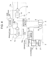
FIG. 4 is a schematic diagram for explaining the configuration according to the fourth embodiment of the present invention. -
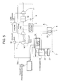
FIG. 5 is a schematic diagram for explaining the configuration according to the fifth embodiment of the present invention. -
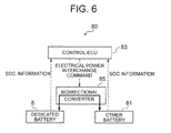
FIG. 6 is a conceptual diagram of the power management system according to the present invention. -
FIG. 7 is a flow chart of control of the power management system according to the present invention. - Embodiments of the present invention will now be described in detail with reference to the accompanying drawings. It is intended, however, that unless particularly specified, dimensions, materials, shapes, relative positions and the like of components described in the embodiments shall be interpreted as illustrative only and not limitative of the scope of the present invention.
- A schematic diagram of the entire configuration of an electric supercharging device utilizing the waste heat of the engine according to the first present invention is shown, where 1 is the engine.
- The exhaust gas discharged from the
engine 1 is introduced into asteam cycle device 2 which converts heat of the exhaust gas into rotation energy via anexhaust gas pipe 1a. The rotation energy of thesteam cycle device 2 drives thefirst generator 5 via amagnet coupling 7 being a non-contact coupling to generate alternate current. The alternate current is converted into direct current by thefirst converter 6 provided adjacent to the first generator 5 (thefirst generator 5 and thefirst converter 6 collectively form the first generating device 3), and then the direct current is stored in thebattery 8 being the first electric storage. - 9 is the electric supercharger which drives the
first compressor 11 connected to amotor 14 powered by the electrical power stored in thebattery 8 to turn the intake air into compressed air, which is introduced into theengine 1. - The
steam cycle device 2 includes anevaporator 24 which changes a medium R from liquid to steam by heat of the exhaust gas and anexpander 25 being a steam turbine which expands and converts the steam having been vaporized in theevaporator 24 into rotation energy. The steam discharged from theexpander 25 is introduced into aneconomizer 23. Inside theeconomizer 23, the medium R, which is to be changed from steam to liquid in the followingcondenser 21, is superheated in advance by heat of the exhaust gas. - After passing through the
economizer 23, the medium R is cooled by thecondenser 21 and changed from steam to liquid. - The medium R having been condensed in the
condenser 21 is transmitted to theeconomizer 23 by thewater supply pump 22 to be preheated by the exhaust gas as described above. The preheated medium R is introduced again into theevaporator 24 and changed from liquid to steam. - Although an alternative chlorofluorocarbon is used as the medium R in the present embodiment, the same effect can be attained with other media that have equivalent function.
- Also, although the
economizer 23 is used in the present embodiment, it can be omitted when the exhaust gas has high temperature and the change from liquid to steam is sufficiently performed by heat of the exhaust gas in theevaporator 24. - Moreover, when the exhaust gas has low temperature and the change from liquid to steam is not sufficiently performed by heat of the exhaust gas in the
evaporator 24, another device may be additionally provided for superheating. - The
first generating device 3 includes thefirst generator 5 being the first alternate current generator and thefirst converter 6, which converts the alternate current generated by thefirst generator 5 into direct current. - The
first generator 5 is configured such that the rotation of theexpander 25 is transmitted to thefirst generator 5 via themagnet coupling 7, which is a non-contact coupling disposed coaxially with theexpander 25. - The
magnet coupling 7 is used as a non-contact rotation transmitting device because seal is required to prevent the medium R (in this case, in the form of steam) from leaking out of theexpander 25. - The
electric supercharger 9 includes aninverter 12 which converts the electrical power from thededicated battery 8 from direct current to alternate current, amotor 14 being driven to rotate by the electrical power converted into direct current by theinverter 12, and thefirst compressor 11 coupled coaxially to themotor 14, thecompressor 11 being configured to compress the intake air and discharge the intake air as compressed air to the engine via theair supply pipe 11a. - Herein, the
dedicated battery 8 is provided because there is possibility that sharing the other electric storage (battery) for operating equipments (devices) which use theengine 1 as the power supply may have negative impact on the operation of the equipments (devices). - Also, in the present embodiment, a
power management system 80 is provided as shown inFig. 6 . In thepower management system 80, the electrical power is interchanged with theother battery 81 being the second electric storage for actuating (operating) existing equipments (devices) using theengine 1 as the power supply when both of the batteries have allowance in the amount of electric storage. - The
power management system 80 includes: acontrol ECU 83 for controlling thededicated battery 8, theother battery 81, and the interchange between the batteries while monitoring SOC (the State of Charge) of each of thebatteries bidirectional converter 85 for interchanging electrical power (electrical current) between thebatteries controller ECU 83. - The
power management system 80 is to interchange electrical power from thededicated battery 8 to theother battery 81 when the amount of electric charge is not less than the so-called required amount of electric charge, that is, the amount of electrical power for driving themotor 14 by thededicated battery 8 in order to obtain necessary compressed air in thefirst compressor 11, and the amount of electric charge of theother battery 81 is less than the required amount of electric charge for actuating (operating) the above existing equipments (devices). - On the other hand, the
power management system 80 is to interchange the electrical power from theother battery 81 to thededicated battery 8 when thededicated battery 8 is short of the required amount of electric charge and theother battery 81 has the amount not less than the required amount of electric charge for actuating (operating) the equipments (devices). - In reference to
Fig .7 , the control flow will now be described based on thepower management system 80. - The process starts in step S1, and then SOC of the
dedicated battery 8 is checked by thecontrol ECU 83 in step S2. The result thereof is displayed at the driver's seat by thecontrol ECU 83 in step S3. - SOC of the
other battery 81 is checked by thecontrol ECU 83 in step S4. The result thereof is displayed at the driver's seat by thecontrol ECU 83 in step S5. - In step S6, the
control ECU 83 determines whether the amount of electric charge of thededicated battery 8 detected in step S2 is not less than the so-called required amount of electric charge, that is, the amount of electrical power for driving themotor 14 in order to obtain necessary compressed air in thefirst compressor 11. When the amount is not less than the required amount of electric charge, YES is selected, proceeding to step S7. Thecontrol ECU 83 determines whether the amount of electric charge of theother battery 81 detected in step S4 is not less than the required amount of electric charge for actuating (operating) the equipments (devices) in S7. When the amount is not less than the required amount of electric charge, the process advances to S8 and then returns. - In this case, the electrical power is not interchanged because both of the
dedicated battery 8 and theother battery 81 have the required amount of electric charge. - When NO is selected in
step 6, that is, when thededicated battery 8 has the amount not greater than the required amount of electric charge, the process proceeds to step S9. Thecontrol ECU 83 determines whether the amount of electric charge for actuating (operating) equipments (devices) ofother batteries 81 detected in step S4 is not less than the required amount of electric charge in S9. When the amount is not less than the required amount of electric charge, the process proceeds to step S10, in which thecontrol ECU 83 transmits an electrical power interchange command for interchanging from theother battery 81 to thededicated battery 8 to thebidirectional converter 85. Thebidirectional converter 85 then executes the command. When the command is executed in step S10, change occurs in SOC of each of thededicated battery 8 and theother battery 81. Thus, the process returns to step S2 to monitor whether thededicated battery 8 has the required amount of electrical charge, and it is also monitors in step S4 whether thebattery 81 have the amount greater than the required amount of electric charge. When NO is selected in step S9, that is, when interchange from theother battery 81 to thededicated battery 8 is not possible (including the case there is the required amount of electric charge but no allowance), the process proceeds to step S8 and no interchange is performed. - When NO is selected in step S7, that is, when the
other battery 81 has the amount not greater than the required amount of electric charge, the process proceeds to step S11. Thecontrol ECU 83 determines whether the amount of electric charge of thededicated battery 8 for driving themotor 14 detected in step S2 is not less than the required amount of electric charge in step S11. When the amount is not less than the required amount of electric charge, the process advances to step S12, in which thecontrol ECU 83 transmits an electrical power interchange command for interchange from thededicated battery 8 to theother battery 81 to thebidirectional converter 85, which then executes the command. When the command is executed in step S12, change occurs in SOC of each of thededicated battery 8 and theother battery 81. Thus, the process returns to step S2, in which it is monitored whether thededicated battery 8 has the amount not greater than the required amount of electric charge. Also, it is constantly monitored whether theother battery 81 has the required amount of electric charge. When NO is selected in step S11, that is, when interchange from theother battery 81 to thededicated battery 8 is not possible (including the case there is the required amount of electric charge but no allowance), the process proceeds to step S8 and no interchange is performed. - With the above configuration, the electrical power generated by waste heat of the engine and stored is used, which makes it possible to generate compressed air in accordance with the operation state of the vehicle without using the electrical power to be supplied to existing electric components for operating devices that use the engine as the power supply.
- Also, as the electric supercharger is used, the electric supercharger does not include turbine and thus increase in the exhaust pressure of the engine is suppressed, which makes it possible to achieve fuel consumption equivalent to that of a naturally-aspirated engine.
- As the electric supercharger is used, it is possible to reduce the cost because the ambient temperature is relatively low and thus high thermal resistance is not required for the motor inverter.
- Further, as the
power management system 80 is provided, the electrical power is interchanged between each other to secure the performance of the function when the amount of electric charge is checked and determined to have become short in the dedicated electric storage device for operating the devices and the other electric storage. Also, when the amount of electric charge is insufficient, the supercharging effect decreases but it does not become zero, which makes it possible to obtain the effect of the amount of minimum requirement without the device being stopped. - Compared to the first embodiment, the present embodiment includes an exhaust
gas turbine generator 15 disposed between thesteam cycle device 2 and theengine 1. Accordingly, the same feature is associated with same reference number to omit the description. - The exhaust gas discharged from the
engine 1 is introduced into the exhaustgas turbine generator 15 being the second generating device via anexhaust gas pipe 1a. The exhaust gas that has driven theexhaust gas turbine 16 of the exhaustgas turbine generator 15 is introduced into thesteam cycle device 2. Thesteam cycle device 2 drives theexpander 25 being a steam turbine to rotate by the steam generated from the liquid medium by heat of the exhaust gas, driving thefirst generator 5 to generate electrical power. The generated electrical current is converted into direct current from alternate current by thefirst converter 6 and then stored in thebattery 8, which is the dedicated electric storage. - Herein, the
expander 25 and thefirst generator 5 are coaxially coupled by themagnet coupling 7. - The electric current of the
battery 8 actuates theelectric supercharger 9, which pressurizes the intake air to obtain compressed air. The compressed air is introduced into a combustion chamber (not shown) of the engine via theair supply pipe 11a. - The exhaust
gas turbine generator 15 includes theexhaust gas turbine 16, asecond generator 51 coaxially coupled to theexhaust gas turbine 16, and asecond converter 61 for converting the electrical current generated by thesecond generator 51 from alternate current to direct current. - The electrical current generated by the
second generator 51 is stored in thededicated battery 8. - With this configuration, the
exhaust gas turbine 16 is driven in the exhaustgas turbine generator 15 to generate electrical power, and the high temperature of the exhaust gas that has driven theexhaust gas turbine 16 is maintained. Thus, theexpander 25 being a steam turbine is driven to rotate by the steam generated by heat of the exhaust gas utilizing heat of the exhaust gas in thesteam cycle 2. - Accordingly, the energy is recovered in two-stage of the exhaust
gas turbine generator 15 and thesteam cycle device 2. As a result, there is high efficiency in recovering energy, which makes it possible to increase the amount of power generation. - Compared to the first embodiment, in the present embodiment, the rotational shaft of the
expander 25 of thesteam cycle device 2 and the rotational shaft of the exhaustgas turbine generator 15 of the second embodiment are coaxially coupled by themagnet coupling 7. - The exhaust gas discharged from the
engine 1 is introduced into the exhaustgas turbine generator 15 via theexhaust gas pipe 1a. The exhaust gas having driven theexhaust gas turbine 16 of the exhaustgas turbine generator 15 is introduced into thesteam cycle device 2. Thesteam cycle device 2 changes liquid medium into steam, and drives theexpander 25 to rotate with the steam. - The exhaust
gas turbine generator 15 includes theexhaust gas turbine 16 that is driven to rotate by the exhaust gas from theengine 1, athird generator 53 disposed on the other end side of the rotation of theexhaust gas turbine 16, and athird converter 63 for converting the electric current generated by thethird generator 53 from alternate current to direct current. - Also, the rotational shaft of the
expander 25 and the rotational shaft of theexhaust gas turbine 16 are coaxially arranged and coupled by themagnet coupling 7, so that theexpander 25 and theexhaust gas turbine 16 are arranged in series. - Further, the electrical current generated by the
third generator 53 is charged in thededicated battery 8 being an electric storage. The electric current of thebattery 8 actuates theelectric supercharger 9, which pressurizes the intake air to obtain compressed air. The compressed air is introduced into a combustion chamber (not shown) of theengine 1 via theair supply pipe 11a. - With this configuration, the
expander 25 and theexhaust gas turbine 16 are arranged in series. As a result, the rotation torque is increased and thus the capacity of thethird generator 53 can be increased, which makes it possible to improve the power generation efficiency. - Further, it is possible to decrease the number of both the
third generators 53 and theconverters 63. As a result, it is possible to reduce the cost as well as to stabilize the quality by the allowance in the design layout for arrangement. - Compared to the first embodiment, the present embodiment includes a
turbocharger 4 between thesteam cycle device 2 and theengine 1 to realize two-stage supercharging. Accordingly, the same feature is associated with the same reference number to omit the description. - The exhaust gas discharged from the
engine 1 is introduced into theturbocharger 4 via theexhaust gas pipe 1a to drive theexhaust gas turbine 16. - The exhaust gas having driven the
exhaust gas turbine 16 is introduced into thesteam cycle device 2. Thesteam cycle device 2 changes the liquid medium into steam, and drives theexpander 25 to rotate with the steam, thereby driving thefirst generator 5 to generate electrical power. The generated electrical current is converted from alternate current to direct current by thefirst converter 6 and stored in thebattery 8 being a dedicated electric storage. - Also, the
expander 25 and thefirst generator 5 are coaxially coupled by themagnet coupling 7. - The electric current of the
battery 8 actuates theelectric supercharger 9, which pressurizes the intake air to obtain compressed air. The compressed air is introduced into a combustion chamber (not shown) of the engine via theair supply pipe 11a. - The
turbocharger 4 includes theexhaust gas turbine 16 driven to rotate by the exhaust gas, asecond compressor 17 attached to the rotational shaft of theexhaust gas turbine 16 and configured to pressurized intake air, and apressure pipe 17a for introducing the compressed air generated by thesecond compressor 17 to the upstream side of thefirst compressor 11 of theelectric supercharger 9. - Accordingly, in the present embodiment, compressed air of the first stage is generated in the
turbocharger 4, and the compressed air is introduced into the intake side, which is the upstream side of thefirst compressor 11 of theelectric supercharger 9. - Then, the compressed air is further pressurized by the
first compressor 11 of theelectric supercharger 9. The first-stage compressed air is generated in theturbocharger 4, and then the compressed air is introduced into the intake side, which is the upstream side of thecompressor 11 of thesupercharger 9, thereby realizing two-stage supercharging. - On the other hand, the exhaust gas having driven the
turbocharger 4 is configured to drive thefirst generator 5 by converting heat energy to rotation energy in thesteam cycle device 2, thereby charging thebattery 8 which serves as the power supply of themotor 14 for driving thefirst compressor 11. - With the above configuration, the turbocharger and the electric supercharger are arranged in series in the air supply system. As a result, it is possible to increase the supercharging pressure and to suppress increase in the exhaust pressure of the engine even though the supercharging pressure is increased, which makes it possible to improve the output of the engine and fuel consumption.
- Compared to the first embodiment, the present embodiment includes a
turbocharger 4 between thesteam cycle device 2 and theengine 1, which realizes two-stage supercharging. The present embodiment also includes awastegate valve 30 for theturbocharger 4 and an exhaustgas processing device 35 on the downstream side of theturbocharger 4. - Accordingly, the same feature is associated with the same reference number to omit the description.
- The exhaust gas discharged from the
engine 1 is introduced into the wastegate valve positioned on the upstream side of theturbocharger 4 in the exhaust gas system via theexhaust gas pipe 1a. The wastegate valve controls the supercharging pressure of theturbocharger 4. - The exhaust gas introduced into the
wastegate valve 30 is introduced into the exhaust gas flowing to theexhaust gas turbine 16 side by supercharging pressure of theturbocharger 4, and the exhaust gas whose flow volume has been adjusted is introduced into thesteam cycle device 2 via thebypass pipe 30a. - The exhaust gas discharged from the
exhaust gas turbine 16 passes through the inside of the exhaustgas processing device 35 and is introduced into thesteam cycle device 2. - The
steam cycle device 2 changes the liquid being a medium into steam, drives theexpander 25 to rotate with the steam, and then drives thefirst generator 5 to generate electrical power. The generated electrical current is converted from alternate current to direct current by thefirst convertor 6 and then stored in thebattery 8, which is a dedicated electric storage. - Herein, the
expander 25 and thefirst generator 5 are coaxially coupled by themagnet coupling 7. - The electric current of the
battery 8 actuates theelectric supercharger 9, which pressurizes the intake air to obtain compressed air. The compressed air is introduced into a combustion chamber (not shown) of theengine 1 via theair supply pipe 11 a. - The
turbocharger 4 includes theexhaust gas turbine 16 driven to rotate by the exhaust gas, asecond compressor 17 attached to the rotational shaft of theexhaust gas turbine 16 and configured to pressurize intake air, and apressure pipe 17a for introducing the compressed air generated by thesecond compressor 17 to the upstream side of thefirst compressor 11 of theelectric supercharger 9. - Accordingly, in the present embodiment, compressed air of the first stage is generated in the
turbocharger 4, and the compressed air is introduced into the intake side, which is the upstream side of thecompressor 11 of theelectric supercharger 9, thereby performing two-stage supercharging. - Also, as the exhaust gas discharged from the
exhaust gas turbine 16 maintains high temperature, the exhaust gas is introduced into the exhaustgas processing device 35 to supercharge the catalyst (oxidation catalyst, SCR catalyst and the like) disposed inside the exhaustgas processing device 35 so as to promote the reaction. - The exhaust gas discharged from the exhaust
gas processing device 35 is merged with the exhaust gas that has flowed through thebypass pipe 30a and is introduced into thesteam cycle device 2. - The effect of heating the catalyst accommodated in the exhaust gas processing device is maintained by arranging the exhaust gas purifying device on the upstream side of the steam cycle device in the exhaust gas system. Also, there is the effect of maintaining high temperature of the exhaust gas temperature introduced into the steam cycle device by introducing the exhaust gas that has bypassed the waste gate to the exhaust gas pipe connecting the exhaust gas purifying device and the steam cycle device. Further, the thermal energy is recovered in the steam cycle device, which makes it possible to improve the efficiency in recovering the exhaust gas energy.
- It is possible to provide a supercharger driving device which recovers waste heat of the internal combustion engine (hereinafter, referred to as "engine") and drives an electric compressor.
Claims (8)
- An electric supercharging device utilizing a waste heat of an internal combustion engine, comprising:a steam cycle device configured to rotate a steam turbine with a steam generated by a heat of an exhaust gas discharged from an engine;a first generating device configured to generate an electrical power by a torque of the steam turbine;a first electric storage which stores the electrical power generated by the first generating device;a motor configured to be driven by the electrical power of the first electric storage; andan electric supercharger configured to drive a compressor with a motor driven by the electrical power of the first electric storage to generate a compressed air.
- The electric supercharging device utilizing a waste heat of an internal combustion engine according to claim 1, further comprising:an exhaust gas turbine disposed on an upstream side of the steam cycle device in an exhaust gas system and configured to be driven by the exhaust gas; anda second generating device connected to the exhaust gas turbine,wherein the electrical power generated by the second generating device is configured to be stored in the first electric storage.
- The electric supercharging device utilizing a waste heat of an internal combustion engine according to claim 1, wherein
the first generative device includes an exhaust gas turbine configured to be driven by the exhaust gas in addition to the steam turbine configured to be driven by the steam, the exhaust gas turbine and the steam turbine being arranged coaxially and in series. - The electric supercharging device utilizing a waste heat of an internal combustion engine according to any of claims 1 to 3, wherein
coupling between rotational shafts of the steam turbine and the exhaust gas turbine, or of the steam turbine and the first generating device is coupled by a non-contact coupling. - The electric supercharging device utilizing a waste heat of an internal combustion engine according to claim 1, further comprising
a turbocharger disposed on the upstream side of the steam cycle device in the exhaust gas system,
wherein the compressed air discharged from the turbocharger or the electric supercharger is configured to be supplied to an intake side of the compressor of one of the turbocharger or the electric supercharger from other one of the turbocharger or the electric supercharger, thereby realizing two-stage supercharging. - The electric supercharging device utilizing a waste heat of an internal combustion engine according to claim 3, further comprising:an exhaust gas purifying device disposed between the steam cycle device and the turbocharger; anda wastegate valve disposed on an upstream side of the turbocharger in an exhaust gas system to adjust an amount of the exhaust gas introduced into the turbocharger,wherein the exhaust gas introduced into the turbocharger is configured to be introduced into the steam cycle device via the exhaust gas purifying device, andwherein the exhaust gas from the wastegate valve is configured to be introduced to the steam cycle device via a bypass line bypassing the exhaust gas turbocharger.
- The electric supercharging device utilizing a waste heat of an internal combustion engine according to any of claims 1 to 6, further comprising
a second electric storage for operating a device whose drive source is the engine,
wherein the electrical power is interchanged between one of the electric storages and other one of the electric storages when one of the first electric storage or the second electric storage has an allowance in a required amount of electric charge required for operation by said one of the electric storages and the other one of the electric storages has an insufficient amount of electric charge to meet the required amount of electric charge. - A power supplying method for an electric supercharging device utilizing a waste heat of an internal combustion engine, the electric supercharging device comprising: a steam cycle device configured to rotate a steam turbine with a steam generated by a heat of an exhaust gas discharged from an engine; a first generating device connected to the steam turbine and configured to generate an electrical power by a torque of the steam turbine; a first electric storage which stores the electrical power generated by the first generating device; a second electric storage for device operation for operating a device whose drive source is the engine; and an electric supercharger configured to drive a compressor with a motor driven by the electrical power of the first electric storage to generate a compressed air, and the method utilizing a waste heat of an internal combustion engine comprising the steps of:checking a state of electric charge of each of the electric storages;determining whether the checked state of electric charge satisfies a required amount of electric charge for usage state of each of the electric storages; andinterchanging the electrical power between one of the electric storages and other one of the electric storages when one of the electric storages has an allowance in the required amount of electric charge and the other one of the electric storages has an insufficient amount of electric charge.
Applications Claiming Priority (2)
| Application Number | Priority Date | Filing Date | Title |
|---|---|---|---|
| JP2011285466A JP5701203B2 (en) | 2011-12-27 | 2011-12-27 | Electric supercharger using waste heat of internal combustion engine |
| PCT/JP2012/077879 WO2013099420A1 (en) | 2011-12-27 | 2012-10-29 | Electric supercharger using waste heat from internal combustion engine and power supply method thereof |
Publications (3)
| Publication Number | Publication Date |
|---|---|
| EP2799687A1 true EP2799687A1 (en) | 2014-11-05 |
| EP2799687A4 EP2799687A4 (en) | 2015-09-02 |
| EP2799687B1 EP2799687B1 (en) | 2019-09-04 |
Family
ID=48696922
Family Applications (1)
| Application Number | Title | Priority Date | Filing Date |
|---|---|---|---|
| EP12861873.3A Not-in-force EP2799687B1 (en) | 2011-12-27 | 2012-10-29 | Electric supercharger using waste heat from internal combustion engine and power supply method thereof |
Country Status (5)
| Country | Link |
|---|---|
| US (1) | US10066532B2 (en) |
| EP (1) | EP2799687B1 (en) |
| JP (1) | JP5701203B2 (en) |
| CN (1) | CN103987937B (en) |
| WO (1) | WO2013099420A1 (en) |
Cited By (2)
| Publication number | Priority date | Publication date | Assignee | Title |
|---|---|---|---|---|
| WO2017106330A3 (en) * | 2015-12-14 | 2017-08-03 | Eaton Corporation | Optimized engine control with electrified intake and exhaust |
| CN108397278A (en) * | 2017-02-06 | 2018-08-14 | 福特环球技术公司 | Method and system for turbocharged engine system |
Families Citing this family (22)
| Publication number | Priority date | Publication date | Assignee | Title |
|---|---|---|---|---|
| JP6377340B2 (en) | 2013-12-04 | 2018-08-22 | 三菱重工業株式会社 | Control device for supercharging system |
| JP6234198B2 (en) | 2013-12-04 | 2017-11-22 | 三菱重工業株式会社 | Turbocharger device |
| JP6294646B2 (en) | 2013-12-04 | 2018-03-14 | 三菱重工業株式会社 | Turbo compound system controller |
| JP6351962B2 (en) | 2013-12-04 | 2018-07-04 | 三菱重工業株式会社 | Turbocharger control device |
| JP6434285B2 (en) | 2013-12-04 | 2018-12-05 | 三菱重工業株式会社 | Control device for supercharging system |
| WO2015090343A1 (en) | 2013-12-19 | 2015-06-25 | Volvo Truck Corporation | Internal combustion engine system |
| EP3034834B1 (en) * | 2014-12-16 | 2019-04-10 | Airbus (Sas) | Method for managing power demand for the operation of an unmanned aircraft provided with an internal combustion engine |
| JP6430270B2 (en) * | 2015-01-26 | 2018-11-28 | 株式会社日立製作所 | Electric regenerative turbocharger |
| CN106285924B (en) * | 2015-06-26 | 2020-05-05 | 张建民 | Device for improving energy utilization rate in tail gas of internal combustion engine |
| US9664140B2 (en) * | 2015-09-23 | 2017-05-30 | Pasteurization Technology Group Inc. | Combined heat and power system with electrical and thermal energy storage |
| JP2019507275A (en) * | 2016-02-01 | 2019-03-14 | ボーグワーナー インコーポレーテッド | Waste heat recovery system and method for internal combustion engine |
| GB201603549D0 (en) * | 2016-03-01 | 2016-04-13 | Aeristech Ltd | Electric supercharger for engines |
| CN106224086B (en) * | 2016-09-18 | 2018-11-23 | 重庆交通大学 | Hybrid electric vehicle engine waste heat reutilization system |
| US10865687B2 (en) * | 2016-11-07 | 2020-12-15 | Ihi Corporation | Exhaust gas energy recovery device |
| CN106640345A (en) * | 2016-12-16 | 2017-05-10 | 大连理工大学 | Waste heat supercharged engine |
| CN109139236B (en) * | 2017-06-16 | 2020-04-24 | 云杉智慧新能源技术有限公司 | Electric supercharging system |
| CN107869396B (en) * | 2017-11-03 | 2020-05-08 | 厦门大学 | Auxiliary ammonia discharge device for mixed ammonia diesel generator |
| JP2020183733A (en) * | 2019-05-09 | 2020-11-12 | 三菱重工業株式会社 | Turbo cluster gas turbine system and method of starting the same |
| DE102019216616A1 (en) * | 2019-10-29 | 2021-04-29 | Siemens Aktiengesellschaft | System with electrical storage for faster start-up of a steam turbine and process |
| JP7606357B2 (en) * | 2021-02-12 | 2024-12-25 | 株式会社Subaru | Supercharging System |
| US11286832B1 (en) * | 2021-04-07 | 2022-03-29 | Scuderi Group, Inc. | Bottoming cycle power system |
| US20240060690A1 (en) * | 2022-08-16 | 2024-02-22 | Scuderi Group, Inc. | Absorption chiller system with a transport membrane heat exchanger |
Family Cites Families (33)
| Publication number | Priority date | Publication date | Assignee | Title |
|---|---|---|---|---|
| CH612471A5 (en) * | 1976-07-01 | 1979-07-31 | Sulzer Ag | Internal combustion engine system |
| JPS5865917A (en) * | 1981-10-15 | 1983-04-19 | Takuma Sogo Kenkyusho:Kk | Power generating device of exhaust heat recovery in diesel engine |
| JPS614814A (en) | 1984-06-16 | 1986-01-10 | Mitsubishi Heavy Ind Ltd | Exhaust gas turbine generating device |
| JP2790753B2 (en) * | 1992-09-04 | 1998-08-27 | 日野自動車工業株式会社 | Engine exhaust energy recovery device |
| US5794431A (en) * | 1993-07-14 | 1998-08-18 | Hitachi, Ltd. | Exhaust recirculation type combined plant |
| JP3704903B2 (en) * | 1997-07-29 | 2005-10-12 | いすゞ自動車株式会社 | Power supply |
| US6644011B2 (en) * | 2000-03-24 | 2003-11-11 | Cheng Power Systems, Inc. | Advanced Cheng Combined Cycle |
| JP2003293782A (en) * | 2002-04-03 | 2003-10-15 | Toyota Motor Corp | Power supply unit for vehicles with turbocharger with motor |
| JP2005009315A (en) * | 2003-06-16 | 2005-01-13 | Nissan Diesel Motor Co Ltd | Two-stage supercharger for engine |
| JP4389739B2 (en) * | 2004-09-29 | 2009-12-24 | 三菱自動車工業株式会社 | Internal combustion engine with a supercharger |
| JP2006177171A (en) * | 2004-12-20 | 2006-07-06 | Toyota Motor Corp | Control device for supercharger with electric motor and automobile equipped with the control device |
| US7849840B2 (en) * | 2005-02-14 | 2010-12-14 | St James David | Electric motor assisted mechanical supercharging system |
| JP2006242154A (en) * | 2005-03-07 | 2006-09-14 | Misuzu Kogyo:Kk | Vehicle engine unit |
| JP2007239566A (en) * | 2006-03-08 | 2007-09-20 | Hino Motors Ltd | Auxiliary equipment for supercharger using exhaust heat energy of EGR gas |
| JP2007263026A (en) * | 2006-03-29 | 2007-10-11 | Fuji Heavy Ind Ltd | Vehicle engine system |
| CN101415908B (en) | 2006-04-12 | 2013-03-13 | 曼柴油机和涡轮公司,德国曼柴油机和涡轮欧洲股份公司的联营公司 | Large turbocharged diesel engine with energy recovery |
| JP2008175126A (en) | 2007-01-18 | 2008-07-31 | Ihi Corp | Turbocharger with motor |
| JP4755127B2 (en) * | 2007-02-28 | 2011-08-24 | 三菱重工業株式会社 | Method and apparatus for cooling electric supercharger |
| JP4592816B2 (en) * | 2007-05-03 | 2010-12-08 | エムエーエヌ・ディーゼル・アンド・ターボ・フィリアル・アフ・エムエーエヌ・ディーゼル・アンド・ターボ・エスイー・ティスクランド | Large turbocharged diesel engine with SCR reactor |
| KR100921046B1 (en) * | 2007-11-07 | 2009-10-08 | 현대자동차주식회사 | Power supply system of vehicle ABS and its power supply method |
| JP2009191686A (en) * | 2008-02-13 | 2009-08-27 | Mazda Motor Corp | Engine supercharger |
| JP4737230B2 (en) * | 2008-05-23 | 2011-07-27 | トヨタ自動車株式会社 | Waste heat recovery system |
| US8407999B2 (en) * | 2008-09-30 | 2013-04-02 | The United States Of America, As Represented By The Administrator Of The U.S. Environmental Protection Agency | Efficiency turbocharged engine system with bottoming cycle, and method of operation |
| JP2010190145A (en) * | 2009-02-19 | 2010-09-02 | Ihi Corp | Supercharging and exhaust emission control system of internal combustion engine |
| JP5328527B2 (en) * | 2009-07-03 | 2013-10-30 | 三菱電機株式会社 | Waste heat regeneration system and control method thereof |
| JP2011094536A (en) * | 2009-10-29 | 2011-05-12 | Mitsubishi Heavy Ind Ltd | Denitration device for ship, and ship provided therewith |
| JP2011106302A (en) * | 2009-11-13 | 2011-06-02 | Mitsubishi Heavy Ind Ltd | Engine waste heat recovery power-generating turbo system and reciprocating engine system including the same |
| JP5086323B2 (en) * | 2009-11-30 | 2012-11-28 | 三菱重工業株式会社 | Waste heat recovery type ship propulsion device, ship equipped with the same, and control method of exhaust heat recovery type ship propulsion device |
| JP4916554B2 (en) | 2010-01-15 | 2012-04-11 | 三菱電機株式会社 | Electric supercharger power control device |
| JP5446960B2 (en) * | 2010-02-15 | 2014-03-19 | 三菱自動車工業株式会社 | Internal combustion engine |
| US20110209473A1 (en) * | 2010-02-26 | 2011-09-01 | Jassin Fritz | System and method for waste heat recovery in exhaust gas recirculation |
| JP5271961B2 (en) * | 2010-05-18 | 2013-08-21 | 三菱重工業株式会社 | Supercharger for internal combustion engine |
| CN201874651U (en) * | 2010-12-04 | 2011-06-22 | 孟庆江 | Engine tail gas generator |
-
2011
- 2011-12-27 JP JP2011285466A patent/JP5701203B2/en not_active Expired - Fee Related
-
2012
- 2012-10-29 WO PCT/JP2012/077879 patent/WO2013099420A1/en not_active Ceased
- 2012-10-29 EP EP12861873.3A patent/EP2799687B1/en not_active Not-in-force
- 2012-10-29 CN CN201280061336.8A patent/CN103987937B/en not_active Expired - Fee Related
- 2012-10-29 US US14/367,952 patent/US10066532B2/en not_active Expired - Fee Related
Cited By (3)
| Publication number | Priority date | Publication date | Assignee | Title |
|---|---|---|---|---|
| WO2017106330A3 (en) * | 2015-12-14 | 2017-08-03 | Eaton Corporation | Optimized engine control with electrified intake and exhaust |
| EP3390799A4 (en) * | 2015-12-14 | 2019-08-14 | Eaton Intelligent Power Limited | Optimized engine control with electrified intake and exhaust |
| CN108397278A (en) * | 2017-02-06 | 2018-08-14 | 福特环球技术公司 | Method and system for turbocharged engine system |
Also Published As
| Publication number | Publication date |
|---|---|
| US10066532B2 (en) | 2018-09-04 |
| EP2799687B1 (en) | 2019-09-04 |
| WO2013099420A1 (en) | 2013-07-04 |
| JP5701203B2 (en) | 2015-04-15 |
| CN103987937B (en) | 2017-10-17 |
| US20150285122A1 (en) | 2015-10-08 |
| CN103987937A (en) | 2014-08-13 |
| JP2013133776A (en) | 2013-07-08 |
| EP2799687A4 (en) | 2015-09-02 |
Similar Documents
| Publication | Publication Date | Title |
|---|---|---|
| US10066532B2 (en) | Electric supercharging device utilizing waste heat of internal combustion engine and power supplying method thereof | |
| JP6294646B2 (en) | Turbo compound system controller | |
| EP2610454A1 (en) | Marine vessel denitration system, marine vessel equipped with same, and control method for marine vessel denitration system | |
| US9096116B2 (en) | Drive with an internal combustion engine and an expansion machine with gas return | |
| JP2012522173A (en) | Reheat gas turbine device, in particular with the fuel cell | |
| CN105649758A (en) | Method and apparatus for operating electric-motor-assisted exhaust turbocharger of motor vehicle | |
| EP2610453A1 (en) | Marine denitration system and marine vessel equipped with the same | |
| KR20080080452A (en) | Drive train, how it works and vehicle | |
| CN103388524B (en) | Diesel engine and the method for improving diesel engine acc power | |
| CN104487661B (en) | Internal combustion engine system, ship equipped with the internal combustion engine system, and operation method of the internal combustion engine system | |
| US9884538B2 (en) | Turbo compound system for vehicle | |
| JP2016138451A (en) | Electric regenerative supercharger | |
| JP5552983B2 (en) | Electric turbo system | |
| EP2482443A1 (en) | Internal combustion engine system and ship | |
| KR20130106495A (en) | Turbo compound system with improved structure | |
| JP2008223509A (en) | Waste heat recovery system and engine | |
| Zhu et al. | Scheme design and assessment of hybrid pump feed system with energy management for throttleable liquid rocket engine | |
| KR101887694B1 (en) | Variable control type turbo compound system for vehicle | |
| US20190048750A1 (en) | Dual mode waste heat recovery expander and control method | |
| JPH04349038A (en) | Device for collecting energy of adiabatic engine and car driving device | |
| KR20130086776A (en) | Turbo compound system for vehicle |
Legal Events
| Date | Code | Title | Description |
|---|---|---|---|
| PUAI | Public reference made under article 153(3) epc to a published international application that has entered the european phase |
Free format text: ORIGINAL CODE: 0009012 |
|
| 17P | Request for examination filed |
Effective date: 20140618 |
|
| AK | Designated contracting states |
Kind code of ref document: A1 Designated state(s): AL AT BE BG CH CY CZ DE DK EE ES FI FR GB GR HR HU IE IS IT LI LT LU LV MC MK MT NL NO PL PT RO RS SE SI SK SM TR |
|
| DAX | Request for extension of the european patent (deleted) | ||
| RA4 | Supplementary search report drawn up and despatched (corrected) |
Effective date: 20150804 |
|
| RIC1 | Information provided on ipc code assigned before grant |
Ipc: F02B 33/34 20060101ALI20150729BHEP Ipc: F02B 37/04 20060101ALI20150729BHEP Ipc: F02D 29/06 20060101ALI20150729BHEP Ipc: F02D 23/00 20060101ALI20150729BHEP Ipc: F02B 37/10 20060101ALI20150729BHEP Ipc: F01N 5/02 20060101ALI20150729BHEP Ipc: F02B 37/18 20060101ALI20150729BHEP Ipc: F02B 39/10 20060101ALI20150729BHEP Ipc: F02B 37/16 20060101ALI20150729BHEP Ipc: F02D 23/02 20060101ALI20150729BHEP Ipc: F01K 23/10 20060101ALI20150729BHEP Ipc: F02G 5/02 20060101ALI20150729BHEP Ipc: F02B 41/10 20060101ALI20150729BHEP Ipc: F02B 37/00 20060101AFI20150729BHEP Ipc: F02G 5/04 20060101ALI20150729BHEP |
|
| 17Q | First examination report despatched |
Effective date: 20160419 |
|
| STAA | Information on the status of an ep patent application or granted ep patent |
Free format text: STATUS: EXAMINATION IS IN PROGRESS |
|
| GRAP | Despatch of communication of intention to grant a patent |
Free format text: ORIGINAL CODE: EPIDOSNIGR1 |
|
| STAA | Information on the status of an ep patent application or granted ep patent |
Free format text: STATUS: GRANT OF PATENT IS INTENDED |
|
| INTG | Intention to grant announced |
Effective date: 20190528 |
|
| GRAS | Grant fee paid |
Free format text: ORIGINAL CODE: EPIDOSNIGR3 |
|
| GRAA | (expected) grant |
Free format text: ORIGINAL CODE: 0009210 |
|
| STAA | Information on the status of an ep patent application or granted ep patent |
Free format text: STATUS: THE PATENT HAS BEEN GRANTED |
|
| AK | Designated contracting states |
Kind code of ref document: B1 Designated state(s): AL AT BE BG CH CY CZ DE DK EE ES FI FR GB GR HR HU IE IS IT LI LT LU LV MC MK MT NL NO PL PT RO RS SE SI SK SM TR |
|
| REG | Reference to a national code |
Ref country code: GB Ref legal event code: FG4D |
|
| REG | Reference to a national code |
Ref country code: CH Ref legal event code: EP |
|
| REG | Reference to a national code |
Ref country code: AT Ref legal event code: REF Ref document number: 1175648 Country of ref document: AT Kind code of ref document: T Effective date: 20190915 |
|
| REG | Reference to a national code |
Ref country code: DE Ref legal event code: R096 Ref document number: 602012063749 Country of ref document: DE |
|
| REG | Reference to a national code |
Ref country code: IE Ref legal event code: FG4D |
|
| REG | Reference to a national code |
Ref country code: NL Ref legal event code: FP |
|
| REG | Reference to a national code |
Ref country code: LT Ref legal event code: MG4D |
|
| PG25 | Lapsed in a contracting state [announced via postgrant information from national office to epo] |
Ref country code: BG Free format text: LAPSE BECAUSE OF FAILURE TO SUBMIT A TRANSLATION OF THE DESCRIPTION OR TO PAY THE FEE WITHIN THE PRESCRIBED TIME-LIMIT Effective date: 20191204 Ref country code: NO Free format text: LAPSE BECAUSE OF FAILURE TO SUBMIT A TRANSLATION OF THE DESCRIPTION OR TO PAY THE FEE WITHIN THE PRESCRIBED TIME-LIMIT Effective date: 20191204 Ref country code: FI Free format text: LAPSE BECAUSE OF FAILURE TO SUBMIT A TRANSLATION OF THE DESCRIPTION OR TO PAY THE FEE WITHIN THE PRESCRIBED TIME-LIMIT Effective date: 20190904 Ref country code: LT Free format text: LAPSE BECAUSE OF FAILURE TO SUBMIT A TRANSLATION OF THE DESCRIPTION OR TO PAY THE FEE WITHIN THE PRESCRIBED TIME-LIMIT Effective date: 20190904 Ref country code: SE Free format text: LAPSE BECAUSE OF FAILURE TO SUBMIT A TRANSLATION OF THE DESCRIPTION OR TO PAY THE FEE WITHIN THE PRESCRIBED TIME-LIMIT Effective date: 20190904 Ref country code: HR Free format text: LAPSE BECAUSE OF FAILURE TO SUBMIT A TRANSLATION OF THE DESCRIPTION OR TO PAY THE FEE WITHIN THE PRESCRIBED TIME-LIMIT Effective date: 20190904 |
|
| PG25 | Lapsed in a contracting state [announced via postgrant information from national office to epo] |
Ref country code: AL Free format text: LAPSE BECAUSE OF FAILURE TO SUBMIT A TRANSLATION OF THE DESCRIPTION OR TO PAY THE FEE WITHIN THE PRESCRIBED TIME-LIMIT Effective date: 20190904 Ref country code: LV Free format text: LAPSE BECAUSE OF FAILURE TO SUBMIT A TRANSLATION OF THE DESCRIPTION OR TO PAY THE FEE WITHIN THE PRESCRIBED TIME-LIMIT Effective date: 20190904 Ref country code: GR Free format text: LAPSE BECAUSE OF FAILURE TO SUBMIT A TRANSLATION OF THE DESCRIPTION OR TO PAY THE FEE WITHIN THE PRESCRIBED TIME-LIMIT Effective date: 20191205 Ref country code: RS Free format text: LAPSE BECAUSE OF FAILURE TO SUBMIT A TRANSLATION OF THE DESCRIPTION OR TO PAY THE FEE WITHIN THE PRESCRIBED TIME-LIMIT Effective date: 20190904 Ref country code: ES Free format text: LAPSE BECAUSE OF FAILURE TO SUBMIT A TRANSLATION OF THE DESCRIPTION OR TO PAY THE FEE WITHIN THE PRESCRIBED TIME-LIMIT Effective date: 20190904 |
|
| REG | Reference to a national code |
Ref country code: AT Ref legal event code: MK05 Ref document number: 1175648 Country of ref document: AT Kind code of ref document: T Effective date: 20190904 |
|
| PG25 | Lapsed in a contracting state [announced via postgrant information from national office to epo] |
Ref country code: PT Free format text: LAPSE BECAUSE OF FAILURE TO SUBMIT A TRANSLATION OF THE DESCRIPTION OR TO PAY THE FEE WITHIN THE PRESCRIBED TIME-LIMIT Effective date: 20200106 Ref country code: IT Free format text: LAPSE BECAUSE OF FAILURE TO SUBMIT A TRANSLATION OF THE DESCRIPTION OR TO PAY THE FEE WITHIN THE PRESCRIBED TIME-LIMIT Effective date: 20190904 Ref country code: EE Free format text: LAPSE BECAUSE OF FAILURE TO SUBMIT A TRANSLATION OF THE DESCRIPTION OR TO PAY THE FEE WITHIN THE PRESCRIBED TIME-LIMIT Effective date: 20190904 Ref country code: AT Free format text: LAPSE BECAUSE OF FAILURE TO SUBMIT A TRANSLATION OF THE DESCRIPTION OR TO PAY THE FEE WITHIN THE PRESCRIBED TIME-LIMIT Effective date: 20190904 Ref country code: PL Free format text: LAPSE BECAUSE OF FAILURE TO SUBMIT A TRANSLATION OF THE DESCRIPTION OR TO PAY THE FEE WITHIN THE PRESCRIBED TIME-LIMIT Effective date: 20190904 Ref country code: RO Free format text: LAPSE BECAUSE OF FAILURE TO SUBMIT A TRANSLATION OF THE DESCRIPTION OR TO PAY THE FEE WITHIN THE PRESCRIBED TIME-LIMIT Effective date: 20190904 |
|
| PG25 | Lapsed in a contracting state [announced via postgrant information from national office to epo] |
Ref country code: CZ Free format text: LAPSE BECAUSE OF FAILURE TO SUBMIT A TRANSLATION OF THE DESCRIPTION OR TO PAY THE FEE WITHIN THE PRESCRIBED TIME-LIMIT Effective date: 20190904 Ref country code: SM Free format text: LAPSE BECAUSE OF FAILURE TO SUBMIT A TRANSLATION OF THE DESCRIPTION OR TO PAY THE FEE WITHIN THE PRESCRIBED TIME-LIMIT Effective date: 20190904 Ref country code: SK Free format text: LAPSE BECAUSE OF FAILURE TO SUBMIT A TRANSLATION OF THE DESCRIPTION OR TO PAY THE FEE WITHIN THE PRESCRIBED TIME-LIMIT Effective date: 20190904 Ref country code: IS Free format text: LAPSE BECAUSE OF FAILURE TO SUBMIT A TRANSLATION OF THE DESCRIPTION OR TO PAY THE FEE WITHIN THE PRESCRIBED TIME-LIMIT Effective date: 20200224 |
|
| REG | Reference to a national code |
Ref country code: CH Ref legal event code: PL |
|
| REG | Reference to a national code |
Ref country code: DE Ref legal event code: R097 Ref document number: 602012063749 Country of ref document: DE |
|
| PLBE | No opposition filed within time limit |
Free format text: ORIGINAL CODE: 0009261 |
|
| STAA | Information on the status of an ep patent application or granted ep patent |
Free format text: STATUS: NO OPPOSITION FILED WITHIN TIME LIMIT |
|
| PG2D | Information on lapse in contracting state deleted |
Ref country code: IS |
|
| PG25 | Lapsed in a contracting state [announced via postgrant information from national office to epo] |
Ref country code: DK Free format text: LAPSE BECAUSE OF FAILURE TO SUBMIT A TRANSLATION OF THE DESCRIPTION OR TO PAY THE FEE WITHIN THE PRESCRIBED TIME-LIMIT Effective date: 20190904 Ref country code: LI Free format text: LAPSE BECAUSE OF NON-PAYMENT OF DUE FEES Effective date: 20191031 Ref country code: CH Free format text: LAPSE BECAUSE OF NON-PAYMENT OF DUE FEES Effective date: 20191031 Ref country code: LU Free format text: LAPSE BECAUSE OF NON-PAYMENT OF DUE FEES Effective date: 20191029 Ref country code: IS Free format text: LAPSE BECAUSE OF FAILURE TO SUBMIT A TRANSLATION OF THE DESCRIPTION OR TO PAY THE FEE WITHIN THE PRESCRIBED TIME-LIMIT Effective date: 20200105 |
|
| 26N | No opposition filed |
Effective date: 20200605 |
|
| REG | Reference to a national code |
Ref country code: BE Ref legal event code: MM Effective date: 20191031 |
|
| PG25 | Lapsed in a contracting state [announced via postgrant information from national office to epo] |
Ref country code: BE Free format text: LAPSE BECAUSE OF NON-PAYMENT OF DUE FEES Effective date: 20191031 Ref country code: SI Free format text: LAPSE BECAUSE OF FAILURE TO SUBMIT A TRANSLATION OF THE DESCRIPTION OR TO PAY THE FEE WITHIN THE PRESCRIBED TIME-LIMIT Effective date: 20190904 Ref country code: MC Free format text: LAPSE BECAUSE OF FAILURE TO SUBMIT A TRANSLATION OF THE DESCRIPTION OR TO PAY THE FEE WITHIN THE PRESCRIBED TIME-LIMIT Effective date: 20190904 |
|
| GBPC | Gb: european patent ceased through non-payment of renewal fee |
Effective date: 20191204 |
|
| PG25 | Lapsed in a contracting state [announced via postgrant information from national office to epo] |
Ref country code: GB Free format text: LAPSE BECAUSE OF NON-PAYMENT OF DUE FEES Effective date: 20191204 Ref country code: FR Free format text: LAPSE BECAUSE OF NON-PAYMENT OF DUE FEES Effective date: 20191104 Ref country code: IE Free format text: LAPSE BECAUSE OF NON-PAYMENT OF DUE FEES Effective date: 20191029 |
|
| PG25 | Lapsed in a contracting state [announced via postgrant information from national office to epo] |
Ref country code: CY Free format text: LAPSE BECAUSE OF FAILURE TO SUBMIT A TRANSLATION OF THE DESCRIPTION OR TO PAY THE FEE WITHIN THE PRESCRIBED TIME-LIMIT Effective date: 20190904 |
|
| PG25 | Lapsed in a contracting state [announced via postgrant information from national office to epo] |
Ref country code: HU Free format text: LAPSE BECAUSE OF FAILURE TO SUBMIT A TRANSLATION OF THE DESCRIPTION OR TO PAY THE FEE WITHIN THE PRESCRIBED TIME-LIMIT; INVALID AB INITIO Effective date: 20121029 Ref country code: MT Free format text: LAPSE BECAUSE OF FAILURE TO SUBMIT A TRANSLATION OF THE DESCRIPTION OR TO PAY THE FEE WITHIN THE PRESCRIBED TIME-LIMIT Effective date: 20190904 |
|
| PGFP | Annual fee paid to national office [announced via postgrant information from national office to epo] |
Ref country code: NL Payment date: 20210915 Year of fee payment: 10 |
|
| PGFP | Annual fee paid to national office [announced via postgrant information from national office to epo] |
Ref country code: DE Payment date: 20210923 Year of fee payment: 10 |
|
| PG25 | Lapsed in a contracting state [announced via postgrant information from national office to epo] |
Ref country code: TR Free format text: LAPSE BECAUSE OF FAILURE TO SUBMIT A TRANSLATION OF THE DESCRIPTION OR TO PAY THE FEE WITHIN THE PRESCRIBED TIME-LIMIT Effective date: 20190904 |
|
| PG25 | Lapsed in a contracting state [announced via postgrant information from national office to epo] |
Ref country code: MK Free format text: LAPSE BECAUSE OF FAILURE TO SUBMIT A TRANSLATION OF THE DESCRIPTION OR TO PAY THE FEE WITHIN THE PRESCRIBED TIME-LIMIT Effective date: 20190904 |
|
| REG | Reference to a national code |
Ref country code: DE Ref legal event code: R119 Ref document number: 602012063749 Country of ref document: DE |
|
| REG | Reference to a national code |
Ref country code: NL Ref legal event code: MM Effective date: 20221101 |
|
| PG25 | Lapsed in a contracting state [announced via postgrant information from national office to epo] |
Ref country code: NL Free format text: LAPSE BECAUSE OF NON-PAYMENT OF DUE FEES Effective date: 20221101 Ref country code: DE Free format text: LAPSE BECAUSE OF NON-PAYMENT OF DUE FEES Effective date: 20230503 |