EP2799684A2 - Internal combustion engine provided with a cooling pump that can be mechanically disconnected - Google Patents
Internal combustion engine provided with a cooling pump that can be mechanically disconnected Download PDFInfo
- Publication number
- EP2799684A2 EP2799684A2 EP14166925.9A EP14166925A EP2799684A2 EP 2799684 A2 EP2799684 A2 EP 2799684A2 EP 14166925 A EP14166925 A EP 14166925A EP 2799684 A2 EP2799684 A2 EP 2799684A2
- Authority
- EP
- European Patent Office
- Prior art keywords
- internal combustion
- combustion engine
- auxiliary shaft
- shaft
- circulation pump
- Prior art date
- Legal status (The legal status is an assumption and is not a legal conclusion. Google has not performed a legal analysis and makes no representation as to the accuracy of the status listed.)
- Granted
Links
Images



Classifications
-
- F—MECHANICAL ENGINEERING; LIGHTING; HEATING; WEAPONS; BLASTING
- F04—POSITIVE - DISPLACEMENT MACHINES FOR LIQUIDS; PUMPS FOR LIQUIDS OR ELASTIC FLUIDS
- F04B—POSITIVE-DISPLACEMENT MACHINES FOR LIQUIDS; PUMPS
- F04B35/00—Piston pumps specially adapted for elastic fluids and characterised by the driving means to their working members, or by combination with, or adaptation to, specific driving engines or motors, not otherwise provided for
- F04B35/002—Piston pumps specially adapted for elastic fluids and characterised by the driving means to their working members, or by combination with, or adaptation to, specific driving engines or motors, not otherwise provided for driven by internal combustion engines
-
- F—MECHANICAL ENGINEERING; LIGHTING; HEATING; WEAPONS; BLASTING
- F01—MACHINES OR ENGINES IN GENERAL; ENGINE PLANTS IN GENERAL; STEAM ENGINES
- F01P—COOLING OF MACHINES OR ENGINES IN GENERAL; COOLING OF INTERNAL-COMBUSTION ENGINES
- F01P5/00—Pumping cooling-air or liquid coolants
- F01P5/10—Pumping liquid coolant; Arrangements of coolant pumps
- F01P5/12—Pump-driving arrangements
-
- F—MECHANICAL ENGINEERING; LIGHTING; HEATING; WEAPONS; BLASTING
- F01—MACHINES OR ENGINES IN GENERAL; ENGINE PLANTS IN GENERAL; STEAM ENGINES
- F01P—COOLING OF MACHINES OR ENGINES IN GENERAL; COOLING OF INTERNAL-COMBUSTION ENGINES
- F01P7/00—Controlling of coolant flow
- F01P7/14—Controlling of coolant flow the coolant being liquid
- F01P7/16—Controlling of coolant flow the coolant being liquid by thermostatic control
- F01P7/162—Controlling of coolant flow the coolant being liquid by thermostatic control by cutting in and out of pumps
-
- F—MECHANICAL ENGINEERING; LIGHTING; HEATING; WEAPONS; BLASTING
- F04—POSITIVE - DISPLACEMENT MACHINES FOR LIQUIDS; PUMPS FOR LIQUIDS OR ELASTIC FLUIDS
- F04D—NON-POSITIVE-DISPLACEMENT PUMPS
- F04D1/00—Radial-flow pumps, e.g. centrifugal pumps; Helico-centrifugal pumps
-
- F—MECHANICAL ENGINEERING; LIGHTING; HEATING; WEAPONS; BLASTING
- F04—POSITIVE - DISPLACEMENT MACHINES FOR LIQUIDS; PUMPS FOR LIQUIDS OR ELASTIC FLUIDS
- F04D—NON-POSITIVE-DISPLACEMENT PUMPS
- F04D13/00—Pumping installations or systems
- F04D13/02—Units comprising pumps and their driving means
- F04D13/021—Units comprising pumps and their driving means containing a coupling
-
- F—MECHANICAL ENGINEERING; LIGHTING; HEATING; WEAPONS; BLASTING
- F04—POSITIVE - DISPLACEMENT MACHINES FOR LIQUIDS; PUMPS FOR LIQUIDS OR ELASTIC FLUIDS
- F04D—NON-POSITIVE-DISPLACEMENT PUMPS
- F04D29/00—Details, component parts, or accessories
- F04D29/04—Shafts or bearings, or assemblies thereof
- F04D29/046—Bearings
- F04D29/049—Roller bearings
-
- F—MECHANICAL ENGINEERING; LIGHTING; HEATING; WEAPONS; BLASTING
- F04—POSITIVE - DISPLACEMENT MACHINES FOR LIQUIDS; PUMPS FOR LIQUIDS OR ELASTIC FLUIDS
- F04D—NON-POSITIVE-DISPLACEMENT PUMPS
- F04D29/00—Details, component parts, or accessories
- F04D29/08—Sealings
- F04D29/10—Shaft sealings
- F04D29/12—Shaft sealings using sealing-rings
- F04D29/126—Shaft sealings using sealing-rings especially adapted for liquid pumps
Definitions
- the present invention relates to an internal combustion engine provided with a cooling pump that can be mechanically disconnected.
- Modern internal combustion engines nearly always comprise a liquid cooling system in which a circulation pump circulates coolant (typically water mixed with an antifreeze substance) along a cooling path which extends in part within the internal combustion engine to remove the heat in excess and in part within a radiator to surrender the heat in excess coming from the internal combustion engine into the external environment.
- coolant typically water mixed with an antifreeze substance
- the circulation pump is directly fed so as to be rotated by the crankshaft by the interposition of a mechanical belt or chain transmission (more rarely by means of gears).
- the circulation pump of the cooling system continues to work by unnecessarily drawing mechanical power from the crankshaft (and thus dissipating mechanical energy). Furthermore, the coolant circulation, although bypassing the radiator, in all cases causes a (minimum, yet not null) cooling of the internal combustion engine, which thus warms up slower than potentially possible.
- the electrically operated circulation pump may be operated only when necessary.
- the circulation pump may require considerable power (particularly when the external temperature is hot and high power delivery is required, like when driving on a race track in summer) which would require the installation of a very high performance (and thus heavy and large) electric motor to activate the circulation pump and of a very high performance (and thus heavy and large) electric generator to generate the electricity needed to activate the circulation pump.
- Patent US1665765 and Patent Application JP2003027942 describe an internal combustion engine having: a cooling system provided with a circulation pump, an auxiliary shaft which transmits the rotation movement to a circulation pump shaft, a mechanical transmission which transmits the rotation movement of the crankshaft to the auxiliary shaft, and a coupling device which is interposed between the circulation pump and the auxiliary shaft and is suited to mechanically connect/disconnect the pump shaft to/from the auxiliary shaft.
- a cooling system provided with a circulation pump
- an auxiliary shaft which transmits the rotation movement to a circulation pump shaft
- a mechanical transmission which transmits the rotation movement of the crankshaft to the auxiliary shaft
- a coupling device which is interposed between the circulation pump and the auxiliary shaft and is suited to mechanically connect/disconnect the pump shaft to/from the auxiliary shaft.
- reference numeral 1 indicates an internal combustion engine as a whole.
- the internal combustion engine 1 comprises a crankcase 2 which houses a crankshaft 3 (diagrammatically shown in figures 6 and 7 ) and two heads 4, which house the cylinders and are arranged in a "V" with a 90° angle between the heads.
- the internal combustion engine 1 comprises a cooling system 5 (diagrammatically shown) for cooling the internal combustion engine 1, which comprises a hydraulic circuit in which a coolant (typically consisting of water mixed with an antifreeze additive) flows.
- the cooling system 5 comprises a circulation pump 6 of the centrifuge type for circulating the coolant along the hydraulic circuit.
- the internal combustion engine 1 comprises an auxiliary shaft 7, which is mounted so as to rotate about a rotation axis 8 and transmits the rotational movement to the circulation pump 6.
- the auxiliary shaft 7 is parallel to the crankshaft 3 and receives movement directly from the crankshaft 3 by means of a mechanical belt (or according to a technical equivalent, a chain) transmission; i.e. the mechanical belt transmission 9 transmits the rotational movement from the crankshaft 3 to the auxiliary shaft 7.
- the internal combustion engine 1 also comprises a coupling device 10 which is interposed between the circulation pump 6 and the auxiliary shaft 7 and is suited to mechanically connect/disconnect the circulation pump 6 to/from the auxiliary shaft 7.
- the auxiliary shaft 7 (together with the circulation pump 6 and the coupling device 10) is arranged above the crankcase 2 of the thermal engine 1 and between the two heads 4, i.e. between the space delimited by the side of the two heads 4 arranged in a "V".
- the circulation pump 6 comprises a pump shaft 11 which is mounted so as to rotate coaxially with the auxiliary shaft 7 (and is thus mounted so as to rotate about the rotation axis 9); the pump shaft 11 supports an impeller 12 which rotates within a pumping chamber 13.
- the coupling device 10 comprises a spring 14, which tends to push the coupling device 10 towards a coupling position (shown in figure 2 ), in which the pump shaft 11 of the circulation pump 6 is integral with the auxiliary shaft 7. Furthermore, the coupling device 10 comprises an actuator 15, which is suited to be activated so as to move the coupling device 10, against the action of the spring 14, from the coupling position (shown in figure 2 ) to a decoupling position (shown in figure 3 ), in which the pump shaft 11 of the circulation pump 6 is disconnected from the auxiliary shaft 7.
- the coupling device 10 is normally coupled, i.e.
- the actuator 15 may be of the active type, i.e. may comprise an electrically controlled actuator which may be remotely operated by an electronic control unit or may be of the passive type, i.e. may comprise a coolant temperature sensitive element (e.g. a thermostat element of the bimetallic type).
- a coolant temperature sensitive element e.g. a thermostat element of the bimetallic type
- the coupling device 10 comprises a sleeve 16 which is provided with a frontal toothing 17 is mounted so as to axially slide about the auxiliary shaft 7, and is provided with axial teeth 18 which engage corresponding axial teeth 19 of the auxiliary shaft 7 to be angularly integral with the auxiliary shaft 7 and at the same time to be able to slide axially with respect to the auxiliary shaft 7 itself.
- the coupling device 10 comprises a sleeve 20 which is provided with a frontal toothing 21, is integral with the pump shaft 11 of the circulation pump 6, and is arranged in front of the sleeve 16 so that the sliding of the sleeve 16 makes the frontal toothing 17 of the sleeve 16 engage/disengage the frontal toothing 21 of the sleeve 20.
- the spring 14 is compressed between the sleeve 16 and an annular abutment 22 integral with the auxiliary shaft 7. Furthermore, the sleeve 16 has an axially oriented annular groove 23 in which an end of the spring 14 is inserted. The sleeve 16 has a circumferentially oriented annular groove 24 which is engaged by a finger 25 of the actuator 15 which transmits the movement generated by the actuator 15 itself to the sleeve 16.
- a single common containing casing (box) 26 within which the circulation pump 6 and the coupling device 10 are housed is provided.
- the coupling device 10 is in an oil bath (i.e. is submerged in oil) to allow the continual lubrication of the sleeves 16 and 20 and the bearings 27 and 28.
- a gland 29 is interposed between the coupling device 10 and the circulation pump 6 and near the circulation pump 6 to contain the water within the pumping chamber 13, i.e.
- the containing casing 26 comprises a leakage discharge channel (not shown) which originates from a "dry" annular zone comprised between the gland 29 on one side and the sealing ring 30 on the other side.
- the pump shaft 11 of the circulation pump 6 is arranged by the side of the auxiliary shaft 7; in other words, the auxiliary shaft 7 ends at the assembly formed by the circulation pump 6 and the coupling device 10.
- the pump shaft 11 of the circulation pump 6 is hollow inside and arranged about the auxiliary shaft 7, which passes through the pump shaft 11 itself; in other words, the auxiliary shaft 7 passes through the assembly formed by the circulation pump 6 and the coupling device 10 within the pump shaft 11 of the circulation pump 6.
- a pair of bearings 31 are interposed between the pump shaft 11 of the circulation pump 6 and the auxiliary shaft 7 to allow a relative rotation between the pump shaft 11 of the circulation pump 6 and the auxiliary shaft 7.
- the auxiliary shaft 7 is mechanically connected to a further belt (or according to a technical equivalent, chain) mechanical transmission 32 intended to activate at least one auxiliary device (e.g. a pump of a power steering device or a compressor of a climate control system).
- the auxiliary shaft 7 protrudes from one side of the internal combustion engine 1 to connect to the mechanical transmission 9 and the auxiliary shaft 7 protrudes from the side opposite to the internal combustion engine 1 to connect to the mechanical transmission 32.
- the two mechanical transmissions 9 and 32 are arranged at the opposite sides of the internal combustion engine 1 and are mechanically connected to opposite ends of the auxiliary shaft 7.
- the mechanical transmission 32 comprises a wheel 33 (a pulley in the case of a belt transmission or a toothed wheel in the case of the chain transmission) which is rigidly fixed to an end of the auxiliary shaft 7 and is engaged by a belt or by a chain (not shown) which activates the auxiliary device (not shown).
- a wheel 33 a pulley in the case of a belt transmission or a toothed wheel in the case of the chain transmission
- the mechanical transmission 9 comprises a wheel 34 (a pulley in the case of a belt transmission or a toothed wheel in the case of a chain transmission) which is rigidly fixed to the crankshaft 3, a wheel 35 (a pulley in the case of a belt transmission or a toothed wheel in the case of a chain transmission) which is rigidly fixed to an end of the auxiliary shaft 7, and two further wheels 36 (pulleys in the case of a belt transmission or toothed wheels in the case of a chain transmission) for controlling the timing of the internal combustion engine 1, i.e. for rotating the camshafts 37 which activate the intake and exhaust valves of the internal combustion engine 1.
- the mechanical transmission 9 constitutes the first demultiplication of the rotation of the crankshaft 3 towards the camshafts 37. Furthermore, the mechanical transmission 9 comprises a flexible transmission element 38 (a belt in the case of a belt transmission or a chain in the case of a chain transmission) which is closed in a ring shape and wound about the wheels 34, 35 and 36 and makes the wheels 34, 35 and 36 integral with each other.
- a flexible transmission element 38 a belt in the case of a belt transmission or a chain in the case of a chain transmission
- Each head 4 of the internal combustion engine 1 comprises a corresponding mechanical transmission 39 which receives movement from the crankshaft 3 by means of the mechanical transmission 9 and activates the two camshafts 37.
- Each mechanical transmission 39 comprises a wheel 40 (a pulley in the case of a belt transmission or a toothed wheel in the case of a chain transmission) which is integral with a corresponding wheel 36 and two wheels 41 (pulleys in the case of a belt transmission or toothed wheels in the case of a chain transmission), each of which is integral with a corresponding camshaft 37.
- each mechanical transmission 39 comprises a flexible transmission element 42 (a belt in the case of a belt transmission or a chain in the case of a chain transmission) which is closed in a ring shape and wound about the wheels 40 and 41 and makes the wheels 40 and 41 integral with each other.
- a flexible transmission element 42 a belt in the case of a belt transmission or a chain in the case of a chain transmission
- the mechanical transmission 9 directly activates both mechanical transmissions 39 of the two heads 4 and consequently, all the camshafts 37 rotate in the same direction; such a solution has some drawbacks because the tappets of one head 4 are inevitably more stressed and thus subjected to greater mechanical wear than the tappets of the other head 4.
- the embodiment shown in figure 7 may be used in which the mechanical transmission 9 directly activates a single mechanical transmission 39, while it indirectly activates the other mechanical transmission 39 (i.e.
- the further mechanical transmission 43 comprises a wheel 44 (a pulley in the case of a belt transmission or a toothed wheel in the case of a chain transmission) which is integral with the wheel 35 of the mechanical transmission 9 and a wheel 45 (a pulley in the case of a belt transmission or a toothed wheel in the case of a chain transmission) which is integral with the wheel 40 of the corresponding mechanical transmission 39.
- the further mechanical transmission 43 comprises a flexible transmission element 46 (a belt in the case of a belt transmission or a chain in the case of a chain transmission) which is closed in a ring shape and wound about the wheels 44 and 45 and makes the wheels 44 and 45 integral with each other.
- the wheel 36 of the mechanical transmission 9 arranged near the further mechanical transmission 43 is mechanically disconnected from the other elements (obviously except for the flexible transmission element 38 of the mechanical transmission 9) and performs the sole function of flexible transmission element 38 of the mechanical transmission 9.
- auxiliary shaft 7 is arranged in central position and rotates in direction opposite to the crankshaft 3 (i.e. is counter-rotating), thus the auxiliary shaft 7 may be unbalanced (i.e. provided with eccentric masses) to balance the internal combustion engine 1 (i.e. to compensate the vibrations generated by the operation of the internal combustion engine 1 at least in part).
- the wheels 34 and 35 of the mechanical transmission 9 it is possible to obtain the desired ratio between the angular speed crankshaft 3 and the angular speed of the auxiliary shaft 7 in order to optimize the balancing operated by the auxiliary shaft 7; in particular, the two wheels 34 and 35 may have the same diameter to impart the same angular speed as the crankshaft 3 to the auxiliary shaft 7 and thus balance the first order moments; alternatively, the diameter of the wheel 35 may be half the diameter of the wheel 34 to impart an angular speed which is double the angular speed of the crankshaft 3 to the auxiliary shaft 7 and thus balance the second order moments. It is worth noting that using the auxiliary shaft 7 of the mechanical transmission 9 as "balancing countershaft" has the advantage of using the same component (the auxiliary shaft 7) for two different functions with an obvious optimization which allows to reduce weight and dimensions.
- the auxiliary shaft 7 could not be used as "balancing countershaft”; in this case, the auxiliary shaft 7 could be made to rotate in the same direction as the crankshaft 3.
- the unbalance of the auxiliary shaft 7 is particularly favorable because it may be obtained by inserting eccentric masses in the two wheels 32 and 35 on the opposite ends of the auxiliary shaft 7 instead of directly in the auxiliary shaft 7: indeed, the diameter of the two wheels 32 and 35 is greater than the diameter of the auxiliary shaft 7 and thus arranging an eccentric weight on the periphery of a wheel 32 or 35 confers a very long arm to the eccentric mass with respect to the rotation axis 8; in this manner, a very small eccentric mass is sufficient, the moment of inertia being the same.
- the auxiliary shaft 7 solely performs the function of balancing countershaft and thus is used to activate neither the circulation pump 6 nor other auxiliary devices; alternatively, the auxiliary shaft 7 activates other auxiliary devices by means of the mechanical transmission 32 but does not activate the circulation pump 6.
- the internal combustion engine 1 described above has many advantages.
- the internal combustion engine 1 described above allows to activate the circulation pump 6 of the cooling system 5 only when actually useful/necessary (i.e. only when the internal combustion engine 1 has reached the optimal working temperature).
- the actuation of the circulation pump 6 of the cooling system 5 is always of the mechanical type and torque is derived directly from the crankshaft 3; in this manner, the actuation of the circulation pump 6 is much more energy-efficient and the electric system does not need to be overdimensioned.
- the actuation of the circulation pump 6 of the cooling system 5 is always guaranteed because the coupling device 10 is normally coupled; i.e. in case of malfunctioning of the actuator 15 of the coupling device 10, the coupling device 10, by virtue of the action of the spring 14, always maintains the coupling device 10 in the coupled position.
- the auxiliary shaft 7 may also be used as balancing countershaft with obvious optimization of weight and dimensions.
- the auxiliary devices may be moved onto the other side of the internal combustion engine 1 with respect to the side from which the crankshaft 3 protrudes, thus freeing up space that may be exploited, for example, to house the mechanical components needed to obtain a selectable four-wheel drive.
- the mechanical transmission 9 is not only used to activate the auxiliary shaft 7 but also to activate the timing (i.e. to rotate the camshafts 37) with obvious optimization of weight and dimensions.
Landscapes
- Engineering & Computer Science (AREA)
- Mechanical Engineering (AREA)
- General Engineering & Computer Science (AREA)
- Chemical & Material Sciences (AREA)
- Combustion & Propulsion (AREA)
- Structures Of Non-Positive Displacement Pumps (AREA)
- Valve-Gear Or Valve Arrangements (AREA)
- Exhaust Gas After Treatment (AREA)
Abstract
Description
- The present invention relates to an internal combustion engine provided with a cooling pump that can be mechanically disconnected.
- Modern internal combustion engines nearly always comprise a liquid cooling system in which a circulation pump circulates coolant (typically water mixed with an antifreeze substance) along a cooling path which extends in part within the internal combustion engine to remove the heat in excess and in part within a radiator to surrender the heat in excess coming from the internal combustion engine into the external environment.
- In most vehicles, the circulation pump is directly fed so as to be rotated by the crankshaft by the interposition of a mechanical belt or chain transmission (more rarely by means of gears).
- When the internal combustion engine is started after a long stop (i.e. one sufficiently long to take the temperature of the internal combustion engine to ambient temperature levels), it would be appropriate not to cool the internal combustion engine in order to promote a rapid reaching of the optimal working temperature; indeed, only when the internal combustion engine is at the optimal working temperature can the maximum energy efficiency and the minimum generation of polluting substances (i.e. maximum ecological efficiency) be achieved. For this purpose, modern internal combustion engines are normally provided with a thermostat valve which bypasses the part of the cooling system dedicated to dispersing the heat into the environment (i.e. the radiator) so that the coolant does not surrender heat into the external environment until the coolant itself reaches a sufficiently high temperature (i.e. reaches the optimal working temperature).
- However, when the internal combustion engine is cold (i.e. colder than the optimal working temperature), the circulation pump of the cooling system continues to work by unnecessarily drawing mechanical power from the crankshaft (and thus dissipating mechanical energy). Furthermore, the coolant circulation, although bypassing the radiator, in all cases causes a (minimum, yet not null) cooling of the internal combustion engine, which thus warms up slower than potentially possible.
- In order to solve such a drawback, it has been suggested to use a circulation pump of the cooling system controlled by a dedicated electric motor, and thus entirely independent from the crankshaft in mechanical terms; in this manner, the electrically operated circulation pump may be operated only when necessary. However, particularly in high performance internal combustion engines, the circulation pump may require considerable power (particularly when the external temperature is hot and high power delivery is required, like when driving on a race track in summer) which would require the installation of a very high performance (and thus heavy and large) electric motor to activate the circulation pump and of a very high performance (and thus heavy and large) electric generator to generate the electricity needed to activate the circulation pump.
- Patent
US1665765 and Patent ApplicationJP2003027942 US1665765 and in Patent ApplicationJP2003027942 - It is the object of the present invention to provide an internal combustion engine provided with a cooling pump which is free from the drawbacks described above and which is easy and cost-effective to make at the same time.
- According to the present invention an internal combustion engine provided with a cooling pump is provided as disclosed in the accompanying claims.
- The present invention will now be described with reference to the accompanying drawings, which illustrate some non-limitative embodiments thereof, in which:
-
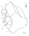
figure 1 is a diagrammatic, perspective view of an internal combustion engine made according to the present invention; -
figure 2 is a diagrammatic, partial, axial section view of an auxiliary shaft of the internal combustion engine infigure 1 coupled to a circulation pump of a cooling system by means of the interposition of a coupling device; -
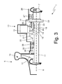
figure 3 is a diagrammatic, partial and axial section view of the auxiliary shaft infigure 2 in which the coupling device is arranged in a decoupling position different from the coupling position shown infigure 2 ; -
figure 4 is a diagrammatic, perspective view of a variant of the internal combustion engine infigure 1 ; -
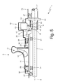
figure 5 is a diagrammatic, partial, axial section view of an auxiliary shaft of the internal combustion engine infigure 4 coupled to a circulation pump of a cooling system by means of the interposition of a coupling device; -
figure 6 is a diagrammatic, front view of a mechanical transmission of the internal combustion engine infigure 1 which activates the auxiliary shaft infigure 2 ; and -
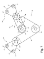
figure 7 is a variant of the mechanical transmission infigure 6 . - In
figure 1 ,reference numeral 1 indicates an internal combustion engine as a whole. - The
internal combustion engine 1 comprises acrankcase 2 which houses a crankshaft 3 (diagrammatically shown infigures 6 and7 ) and twoheads 4, which house the cylinders and are arranged in a "V" with a 90° angle between the heads. - The
internal combustion engine 1 comprises a cooling system 5 (diagrammatically shown) for cooling theinternal combustion engine 1, which comprises a hydraulic circuit in which a coolant (typically consisting of water mixed with an antifreeze additive) flows. Thecooling system 5 comprises acirculation pump 6 of the centrifuge type for circulating the coolant along the hydraulic circuit. - The
internal combustion engine 1 comprises anauxiliary shaft 7, which is mounted so as to rotate about arotation axis 8 and transmits the rotational movement to thecirculation pump 6. According to a preferred embodiment, theauxiliary shaft 7 is parallel to thecrankshaft 3 and receives movement directly from thecrankshaft 3 by means of a mechanical belt (or according to a technical equivalent, a chain) transmission; i.e. themechanical belt transmission 9 transmits the rotational movement from thecrankshaft 3 to theauxiliary shaft 7. Theinternal combustion engine 1 also comprises acoupling device 10 which is interposed between thecirculation pump 6 and theauxiliary shaft 7 and is suited to mechanically connect/disconnect thecirculation pump 6 to/from theauxiliary shaft 7. - According to a preferred embodiment, shown in
figure 1 , the auxiliary shaft 7 (together with thecirculation pump 6 and the coupling device 10) is arranged above thecrankcase 2 of thethermal engine 1 and between the twoheads 4, i.e. between the space delimited by the side of the twoheads 4 arranged in a "V". - As shown in
figure 2 , thecirculation pump 6 comprises apump shaft 11 which is mounted so as to rotate coaxially with the auxiliary shaft 7 (and is thus mounted so as to rotate about the rotation axis 9); thepump shaft 11 supports animpeller 12 which rotates within apumping chamber 13. - The
coupling device 10 comprises aspring 14, which tends to push thecoupling device 10 towards a coupling position (shown infigure 2 ), in which thepump shaft 11 of thecirculation pump 6 is integral with theauxiliary shaft 7. Furthermore, thecoupling device 10 comprises anactuator 15, which is suited to be activated so as to move thecoupling device 10, against the action of thespring 14, from the coupling position (shown infigure 2 ) to a decoupling position (shown infigure 3 ), in which thepump shaft 11 of thecirculation pump 6 is disconnected from theauxiliary shaft 7. By virtue of the presence of thespring 14, thecoupling device 10 is normally coupled, i.e. in the absence of control thecoupling device 10 is in the coupling position (shown infigure 2 ); such a feature privileges the integrity of theinternal combustion engine 1, because the operation of thecirculation pump 6 is always guaranteed in case of problems to theactuator 15, and thus the cooling of theinternal combustion engine 1 is guaranteed. - The
actuator 15 may be of the active type, i.e. may comprise an electrically controlled actuator which may be remotely operated by an electronic control unit or may be of the passive type, i.e. may comprise a coolant temperature sensitive element (e.g. a thermostat element of the bimetallic type). - The
coupling device 10 comprises asleeve 16 which is provided with afrontal toothing 17 is mounted so as to axially slide about theauxiliary shaft 7, and is provided withaxial teeth 18 which engage correspondingaxial teeth 19 of theauxiliary shaft 7 to be angularly integral with theauxiliary shaft 7 and at the same time to be able to slide axially with respect to theauxiliary shaft 7 itself. Furthermore, thecoupling device 10 comprises asleeve 20 which is provided with afrontal toothing 21, is integral with thepump shaft 11 of thecirculation pump 6, and is arranged in front of thesleeve 16 so that the sliding of thesleeve 16 makes the frontal toothing 17 of thesleeve 16 engage/disengage the frontal toothing 21 of thesleeve 20. - According to a preferred embodiment, the
spring 14 is compressed between thesleeve 16 and anannular abutment 22 integral with theauxiliary shaft 7. Furthermore, thesleeve 16 has an axially oriented annular groove 23 in which an end of thespring 14 is inserted. Thesleeve 16 has a circumferentially orientedannular groove 24 which is engaged by afinger 25 of theactuator 15 which transmits the movement generated by theactuator 15 itself to thesleeve 16. - According to a preferred embodiment, a single common containing casing (box) 26 within which the
circulation pump 6 and thecoupling device 10 are housed is provided. There is (at least) one bearing 27 interposed between the containingcasing 26 and theauxiliary shaft 7, while there is (at least) one bearing 28 interposed between the containingcasing 26 and thepump shaft 11 of thecirculation pump 6. According to a preferred embodiment, thecoupling device 10 is in an oil bath (i.e. is submerged in oil) to allow the continual lubrication of thesleeves bearings gland 29 is interposed between thecoupling device 10 and thecirculation pump 6 and near thecirculation pump 6 to contain the water within thepumping chamber 13, i.e. to prevent the leakage of water outside thecirculation pump 6; furthermore, asealing ring 30 is arranged between thecoupling device 10 and thecirculation pump 6 and near thecoupling device 10 to contain the oil within thecoupling device 10, i.e. to prevent the leakage of oil outside thecoupling device 10. According to a preferred embodiment, the containingcasing 26 comprises a leakage discharge channel (not shown) which originates from a "dry" annular zone comprised between thegland 29 on one side and thesealing ring 30 on the other side. - In the embodiment shown in
figures 1 ,2 and3 , thepump shaft 11 of thecirculation pump 6 is arranged by the side of theauxiliary shaft 7; in other words, theauxiliary shaft 7 ends at the assembly formed by thecirculation pump 6 and thecoupling device 10. - In the embodiment shown in
figures 4 and5 , thepump shaft 11 of thecirculation pump 6 is hollow inside and arranged about theauxiliary shaft 7, which passes through thepump shaft 11 itself; in other words, theauxiliary shaft 7 passes through the assembly formed by thecirculation pump 6 and thecoupling device 10 within thepump shaft 11 of thecirculation pump 6. As shown infigure 5 , in this embodiment a pair ofbearings 31 are interposed between thepump shaft 11 of thecirculation pump 6 and theauxiliary shaft 7 to allow a relative rotation between thepump shaft 11 of thecirculation pump 6 and theauxiliary shaft 7. - As shown in
figure 4 , on the side opposite to themechanical transmission 9, theauxiliary shaft 7 is mechanically connected to a further belt (or according to a technical equivalent, chain)mechanical transmission 32 intended to activate at least one auxiliary device (e.g. a pump of a power steering device or a compressor of a climate control system). In other words, theauxiliary shaft 7 protrudes from one side of theinternal combustion engine 1 to connect to themechanical transmission 9 and theauxiliary shaft 7 protrudes from the side opposite to theinternal combustion engine 1 to connect to themechanical transmission 32. In this manner, the twomechanical transmissions internal combustion engine 1 and are mechanically connected to opposite ends of theauxiliary shaft 7. - As shown in
figure 4 , themechanical transmission 32 comprises a wheel 33 (a pulley in the case of a belt transmission or a toothed wheel in the case of the chain transmission) which is rigidly fixed to an end of theauxiliary shaft 7 and is engaged by a belt or by a chain (not shown) which activates the auxiliary device (not shown). - As shown in
figure 6 , themechanical transmission 9 comprises a wheel 34 (a pulley in the case of a belt transmission or a toothed wheel in the case of a chain transmission) which is rigidly fixed to thecrankshaft 3, a wheel 35 (a pulley in the case of a belt transmission or a toothed wheel in the case of a chain transmission) which is rigidly fixed to an end of theauxiliary shaft 7, and two further wheels 36 (pulleys in the case of a belt transmission or toothed wheels in the case of a chain transmission) for controlling the timing of theinternal combustion engine 1, i.e. for rotating thecamshafts 37 which activate the intake and exhaust valves of theinternal combustion engine 1. In other words, themechanical transmission 9 constitutes the first demultiplication of the rotation of thecrankshaft 3 towards thecamshafts 37. Furthermore, themechanical transmission 9 comprises a flexible transmission element 38 (a belt in the case of a belt transmission or a chain in the case of a chain transmission) which is closed in a ring shape and wound about thewheels wheels - Each
head 4 of theinternal combustion engine 1 comprises a correspondingmechanical transmission 39 which receives movement from thecrankshaft 3 by means of themechanical transmission 9 and activates the twocamshafts 37. Eachmechanical transmission 39 comprises a wheel 40 (a pulley in the case of a belt transmission or a toothed wheel in the case of a chain transmission) which is integral with acorresponding wheel 36 and two wheels 41 (pulleys in the case of a belt transmission or toothed wheels in the case of a chain transmission), each of which is integral with acorresponding camshaft 37. Furthermore, eachmechanical transmission 39 comprises a flexible transmission element 42 (a belt in the case of a belt transmission or a chain in the case of a chain transmission) which is closed in a ring shape and wound about thewheels wheels - In the embodiment shown in
figure 6 , themechanical transmission 9 directly activates bothmechanical transmissions 39 of the twoheads 4 and consequently, all thecamshafts 37 rotate in the same direction; such a solution has some drawbacks because the tappets of onehead 4 are inevitably more stressed and thus subjected to greater mechanical wear than the tappets of theother head 4. In order to avoid stressing the tappets of onehead 4 more, the embodiment shown infigure 7 may be used in which themechanical transmission 9 directly activates a singlemechanical transmission 39, while it indirectly activates the other mechanical transmission 39 (i.e. by means of the interposition of a further mechanical transmission 43); by virtue of the presence of the furthermechanical transmission 43, the direction of rotation of themechanical transmission 39, which is coupled to the furthermechanical transmission 43, is reversed and thus thecamshafts 37 of onehead 4 rotate in the opposite direction to thecamshafts 37 of theother head 4. In this manner, the twoheads 4 are perfectly symmetric and thus the tappets of the twoheads 4 are mechanically stressed exactly in the same manner. - The further
mechanical transmission 43 comprises a wheel 44 (a pulley in the case of a belt transmission or a toothed wheel in the case of a chain transmission) which is integral with thewheel 35 of themechanical transmission 9 and a wheel 45 (a pulley in the case of a belt transmission or a toothed wheel in the case of a chain transmission) which is integral with thewheel 40 of the correspondingmechanical transmission 39. Furthermore, the furthermechanical transmission 43 comprises a flexible transmission element 46 (a belt in the case of a belt transmission or a chain in the case of a chain transmission) which is closed in a ring shape and wound about thewheels wheels wheel 36 of themechanical transmission 9 arranged near the furthermechanical transmission 43 is mechanically disconnected from the other elements (obviously except for theflexible transmission element 38 of the mechanical transmission 9) and performs the sole function offlexible transmission element 38 of themechanical transmission 9. - It is worth noting that the
auxiliary shaft 7 is arranged in central position and rotates in direction opposite to the crankshaft 3 (i.e. is counter-rotating), thus theauxiliary shaft 7 may be unbalanced (i.e. provided with eccentric masses) to balance the internal combustion engine 1 (i.e. to compensate the vibrations generated by the operation of theinternal combustion engine 1 at least in part). Obviously, by appropriately dimensioning thewheels mechanical transmission 9 it is possible to obtain the desired ratio between theangular speed crankshaft 3 and the angular speed of theauxiliary shaft 7 in order to optimize the balancing operated by theauxiliary shaft 7; in particular, the twowheels crankshaft 3 to theauxiliary shaft 7 and thus balance the first order moments; alternatively, the diameter of thewheel 35 may be half the diameter of thewheel 34 to impart an angular speed which is double the angular speed of thecrankshaft 3 to theauxiliary shaft 7 and thus balance the second order moments. It is worth noting that using theauxiliary shaft 7 of themechanical transmission 9 as "balancing countershaft" has the advantage of using the same component (the auxiliary shaft 7) for two different functions with an obvious optimization which allows to reduce weight and dimensions. - According to a different embodiment, the
auxiliary shaft 7 could not be used as "balancing countershaft"; in this case, theauxiliary shaft 7 could be made to rotate in the same direction as thecrankshaft 3. - In the embodiment shown in
figures 4 and5 , the unbalance of theauxiliary shaft 7 is particularly favorable because it may be obtained by inserting eccentric masses in the twowheels auxiliary shaft 7 instead of directly in the auxiliary shaft 7: indeed, the diameter of the twowheels auxiliary shaft 7 and thus arranging an eccentric weight on the periphery of awheel rotation axis 8; in this manner, a very small eccentric mass is sufficient, the moment of inertia being the same. - According to a further embodiment not shown, the
auxiliary shaft 7 solely performs the function of balancing countershaft and thus is used to activate neither thecirculation pump 6 nor other auxiliary devices; alternatively, theauxiliary shaft 7 activates other auxiliary devices by means of themechanical transmission 32 but does not activate thecirculation pump 6. - The
internal combustion engine 1 described above has many advantages. - Firstly, the
internal combustion engine 1 described above allows to activate thecirculation pump 6 of thecooling system 5 only when actually useful/necessary (i.e. only when theinternal combustion engine 1 has reached the optimal working temperature). - Furthermore, in the
internal combustion engine 1 described above the actuation of thecirculation pump 6 of thecooling system 5 is always of the mechanical type and torque is derived directly from thecrankshaft 3; in this manner, the actuation of thecirculation pump 6 is much more energy-efficient and the electric system does not need to be overdimensioned. - In the
internal combustion engine 1 described above the actuation of thecirculation pump 6 of thecooling system 5 is always guaranteed because thecoupling device 10 is normally coupled; i.e. in case of malfunctioning of theactuator 15 of thecoupling device 10, thecoupling device 10, by virtue of the action of thespring 14, always maintains thecoupling device 10 in the coupled position. - In the
internal combustion engine 1 described above, theauxiliary shaft 7 may also be used as balancing countershaft with obvious optimization of weight and dimensions. - In the
internal combustion engine 1 described above, in particular in the embodiment shown infigures 4 and5 , the auxiliary devices may be moved onto the other side of theinternal combustion engine 1 with respect to the side from which thecrankshaft 3 protrudes, thus freeing up space that may be exploited, for example, to house the mechanical components needed to obtain a selectable four-wheel drive. - Finally, in the
internal combustion engine 1 described above, themechanical transmission 9 is not only used to activate theauxiliary shaft 7 but also to activate the timing (i.e. to rotate the camshafts 37) with obvious optimization of weight and dimensions.
Claims (17)
- An internal combustion engine (1) comprising:a crankshaft (3);a cooling system (5) provided with a circulation pump (6), which comprises an impeller (12) supported by a pump shaft (11) that is mounted so as to rotate around a rotation axis (8);an auxiliary shaft (7), which transmits the rotation movement to the pump shaft (11) of the circulation pump (6);a first mechanical transmission (9), which transmits the rotational movement from the crankshaft (3) to the auxiliary shaft (7); anda coupling device (10), which is interposed between the pump shaft (11) of the circulation pump (6) and the auxiliary shaft (7) and is suited to mechanically connect/disconnect the pump shaft (11) to/from the auxiliary shaft (7);the internal combustion engine (1) is characterized in that the auxiliary shaft (7) rotates in an opposite direction with respect to the crankshaft (3) and is unbalanced so as to act as balancing countershaft.
- An internal combustion engine (1) according to claim 1, wherein the coupling device (10) comprises:a spring (14), which tends to push the coupling device (10) towards a coupling position, in which the pump shaft (11) of the circulation pump (6) is integral to the auxiliary shaft (7); andan actuator (15), which is suited to be activated so as to move the coupling device (10), against the action of the spring (14), from the coupling position to a decoupling position, in which the pump shaft (11) of the circulation pump (6) is disconnected from the auxiliary shaft (7).
- An internal combustion engine (1) according to claim 2, wherein the coupling device (10) comprises:a first sleeve (16), which is provided with a first frontal toothing (17), is mounted so as to axially slide around the auxiliary shaft (7), and is provided with axial teeth (18), which engage corresponding axial teeth (19) of the auxiliary shaft (7), so as to be angularly integral to the auxiliary shaft (7) itself; anda second sleeve (20), which is provided with a second frontal toothing (21), is integral to the pump shaft (11) of the circulation pump (6), and is arranged in front of the first sleeve (16), so that the sliding movement of the first sleeve (16) causes the first frontal toothing (17) of the first sleeve (16) to engage/disengage the second frontal toothing (21) of the second sleeve (20).
- An internal combustion engine (1) according to claim 3, wherein the spring (14) is compressed between the first sleeve (16) and an annular abutment (22), which is integral to the auxiliary shaft (7).
- An internal combustion engine (1) according to claim 4, wherein the first sleeve (16) has an annular groove (23), into which an end of the spring (14) is inserted.
- An internal combustion engine (1) according to any of the claims from 1 to 5, wherein the pump shaft (11) of the circulation pump (6) is internally hollow and is arranged around the auxiliary shaft (7), which extends through the pump shaft (11) itself.
- An internal combustion engine (1) according to claim 6, wherein a pair of bearings is interposed between the pump shaft (11) of the circulation pump (6) and the auxiliary shaft (7).
- An internal combustion engine (1) according to any of the claims from 1 to 7 and comprising a single common containing casing (26), which houses the circulation pump (6) and the coupling device (10); the coupling device (10) is in an oil bath and between the coupling device (10) and the circulation pump (6) there are interposed a gland (29), which is arranged close to the circulation pump (6), and a sealing ring (30), which is arranged close to the coupling device (10).
- An internal combustion engine (1) according to claim 8, wherein the containing casing (26) comprises a leakage discharge channel, which originates from an annular area comprised between the gland (29) on one side and the sealing ring (30) on the other side.
- An internal combustion engine (1) according to any of the claims from 1 to 9 and comprising a crankcase (2), which houses the crankshaft (3) and two heads (4), which house the cylinders and are arranged in a "V" shape; the auxiliary shaft (7) and the circulation pump (6) are arranged above the crankcase (2) between the two heads (4).
- An internal combustion engine (1) according to claim 10 and comprising a second mechanical transmission (32), which is arranged on the opposite side of the internal combustion engine (1) with respect to the first mechanical transmission (9), receives the rotation movement from the auxiliary shaft (7), and activates at least one auxiliary device.
- An internal combustion engine (1) according to claims 10 and 11, wherein the first mechanical transmission (9) controls the timing by causing the rotation of camshafts (37) that activate the intake and exhaust valves.
- An internal combustion engine (1) according to claim 12, wherein the first mechanical transmission (9) comprises:a first wheel (34), which is rigidly fixed to the crankshaft (3);a second wheel (35), which is rigidly fixed to the auxiliary shaft (7);two third wheels (36), each of which is coupled to a corresponding head (4) and transmits the movement to corresponding camshafts (37); anda first flexible transmission element (38), which is closed in a ring shape and is wound around the first wheel (34), the second wheel (35) and the third wheels (36).
- An internal combustion engine (1) according to claim 13, wherein each head (4) comprises a corresponding third mechanical transmission (39), which receives the rotation movement from a third wheel (36) of the first mechanical transmission (9) and causes the rotation of at least one respective camshaft (37).
- An internal combustion engine (1) according to claim 14, wherein the first mechanical transmission (9) comprises:a first wheel (34), which is rigidly fixed to the crankshaft (3);a second wheel (35), which is rigidly fixed to the auxiliary shaft (7);a third wheel (36), which is coupled to a first head (4) and transmits the movement to corresponding camshafts (37) of the first head (4);a first flexible transmission element (38), which is closed in a ring shape and is wound around the first wheel (34), the second wheel (35) and the third wheel (36); anda fourth mechanical transmission (43), which receives the motion from the second wheel (35) and transmits the movement to corresponding camshafts (37) of a second head (4) that is opposite to the first head (4).
- An internal combustion engine (1) according to claim 15, wherein each head (4) comprises a corresponding third mechanical transmission (39), which receives the rotation movement from the third wheel (36) of the first mechanical transmission (9) or from the fourth mechanical transmission (43) and causes the rotation of corresponding camshafts (37).
- An internal combustion engine (1) comprising:a crankshaft (3);a cooling system (5) provided with a circulation pump (6), which comprises an impeller (12) supported by a pump shaft (11) that is mounted so as to rotate around a rotation axis (8);an auxiliary shaft (7), which transmits the rotation movement to the pump shaft (11) of the circulation pump (6);a first mechanical transmission (9), which transmits the rotational movement from the crankshaft (3) to the auxiliary shaft (7); anda coupling device (10), which is interposed between the pump shaft (11) of the circulation pump (6) and the auxiliary shaft (7) and is suited to mechanically connect/disconnect the pump shaft (11) to/from the auxiliary shaft (7);the internal combustion engine (1) is characterized in that it comprises a crankcase (2) which houses the crankshaft (3) and two heads (4), which house the cylinders and are arranged in a "V"; the auxiliary shaft (7) and the circulation pump (6) are arranged over the crankcase (2) between the two heads (4).
Applications Claiming Priority (1)
| Application Number | Priority Date | Filing Date | Title |
|---|---|---|---|
| IT000195A ITBO20130195A1 (en) | 2013-05-03 | 2013-05-03 | INTERNAL COMBUSTION ENGINE PROVIDED WITH A COOLING PUMP MECHANICALLY DISCONNECTED |
Publications (3)
| Publication Number | Publication Date |
|---|---|
| EP2799684A2 true EP2799684A2 (en) | 2014-11-05 |
| EP2799684A3 EP2799684A3 (en) | 2016-04-06 |
| EP2799684B1 EP2799684B1 (en) | 2017-08-30 |
Family
ID=48808428
Family Applications (1)
| Application Number | Title | Priority Date | Filing Date |
|---|---|---|---|
| EP14166925.9A Active EP2799684B1 (en) | 2013-05-03 | 2014-05-02 | Internal combustion engine provided with a cooling pump that can be mechanically disconnected |
Country Status (3)
| Country | Link |
|---|---|
| US (1) | US9970425B2 (en) |
| EP (1) | EP2799684B1 (en) |
| IT (1) | ITBO20130195A1 (en) |
Cited By (1)
| Publication number | Priority date | Publication date | Assignee | Title |
|---|---|---|---|---|
| CN110657104A (en) * | 2018-06-29 | 2020-01-07 | 北京汽车动力总成有限公司 | Water pump, engine and car |
Citations (2)
| Publication number | Priority date | Publication date | Assignee | Title |
|---|---|---|---|---|
| US1665765A (en) | 1926-02-15 | 1928-04-10 | American Steam Pump Company | Pump attachment for motor vehicles |
| JP2003027942A (en) | 2001-07-16 | 2003-01-29 | Nippon Soken Inc | Early engine warm-up device |
Family Cites Families (12)
| Publication number | Priority date | Publication date | Assignee | Title |
|---|---|---|---|---|
| DE1110480B (en) * | 1957-07-01 | 1961-07-06 | Goetzewerke | Sealing of reciprocating or rotatable cylindrical machine parts, in particular pistons, that can move relative to one another |
| US4269293A (en) * | 1979-03-05 | 1981-05-26 | The Garrett Corporation | Engine accessory disconnect |
| USRE37798E1 (en) * | 1984-05-01 | 2002-07-23 | Yamaha Hatsudoki Kabushiki Kaisha | Valve driving means for V-type engine of vehicle |
| US4756280A (en) * | 1984-12-21 | 1988-07-12 | Kawasaki Jukogyo Kabushiki Kaisha | Cooling system for vertical shaft V-type engine |
| US5482432A (en) * | 1990-07-09 | 1996-01-09 | Deco-Grand, Inc. | Bearingless automotive coolant pump with in-line drive |
| DE10020485A1 (en) | 2000-04-26 | 2001-11-08 | Bayerische Motoren Werke Ag | Cooling system for a liquid-cooled internal combustion engine |
| DE10127219A1 (en) * | 2001-05-23 | 2002-11-28 | Behr Thermot Tronik Gmbh | Cooling system for internal combustion engine has coolant outlet of one row of cylinders connected to radiator inlet, that of another connected to thermostatic valve short circuit inlet |
| US6955141B2 (en) * | 2003-08-06 | 2005-10-18 | General Motors Corporation | Engine cooling system |
| WO2005028901A1 (en) | 2003-09-17 | 2005-03-31 | Plastech Engineering Gmbh | Auxiliary unit drive for a vehicle engine, comprising a couplable and uncouplable pulley, and auxiliary unit |
| US7424941B2 (en) * | 2006-03-22 | 2008-09-16 | Liu Jen-Chih | Clutch device with buffer function |
| DE102006032793B4 (en) * | 2006-07-14 | 2008-06-26 | Dr.Ing.H.C. F. Porsche Ag | Internal combustion engine |
| JP4858368B2 (en) * | 2007-09-11 | 2012-01-18 | スズキ株式会社 | Engine balancer equipment |
-
2013
- 2013-05-03 IT IT000195A patent/ITBO20130195A1/en unknown
-
2014
- 2014-05-02 EP EP14166925.9A patent/EP2799684B1/en active Active
- 2014-05-02 US US14/268,103 patent/US9970425B2/en active Active
Patent Citations (2)
| Publication number | Priority date | Publication date | Assignee | Title |
|---|---|---|---|---|
| US1665765A (en) | 1926-02-15 | 1928-04-10 | American Steam Pump Company | Pump attachment for motor vehicles |
| JP2003027942A (en) | 2001-07-16 | 2003-01-29 | Nippon Soken Inc | Early engine warm-up device |
Cited By (2)
| Publication number | Priority date | Publication date | Assignee | Title |
|---|---|---|---|---|
| CN110657104A (en) * | 2018-06-29 | 2020-01-07 | 北京汽车动力总成有限公司 | Water pump, engine and car |
| CN110657104B (en) * | 2018-06-29 | 2020-12-25 | 北京汽车动力总成有限公司 | Water pump, engine and car |
Also Published As
| Publication number | Publication date |
|---|---|
| US20140328703A1 (en) | 2014-11-06 |
| US9970425B2 (en) | 2018-05-15 |
| EP2799684A3 (en) | 2016-04-06 |
| EP2799684B1 (en) | 2017-08-30 |
| ITBO20130195A1 (en) | 2014-11-04 |
Similar Documents
| Publication | Publication Date | Title |
|---|---|---|
| CN100529362C (en) | Electrically driven camshaft adjuster | |
| CN102597578B (en) | Drive device for vehicle | |
| US9074656B2 (en) | Drive train of a motor vehicle having an internal combustion engine and a starter generator | |
| US20090176611A1 (en) | Auxiliary Unit Drive for a motor vehicle | |
| JP5759556B2 (en) | Waste heat recovery device | |
| US5209194A (en) | Variable valve timing apparatus | |
| US20190351753A1 (en) | Hybrid module for a motor vehicle, and drive train having a hybrid module | |
| US9206861B2 (en) | Integrated switchable shaft bearing | |
| EP2778479B1 (en) | Supercharger | |
| JP2010500205A (en) | Driving device for auxiliary assembly device for automobile | |
| CN102777246A (en) | Internal combustion engine comprising a liquid cooling system and oil supply and method for operating such an internal combustion engine | |
| CN102400730B (en) | Valve timing phase control device | |
| JP5404887B2 (en) | Refrigerant pressure feeding device and method for driving refrigerant pressure feeding device | |
| EP2799684B1 (en) | Internal combustion engine provided with a cooling pump that can be mechanically disconnected | |
| US20130309103A1 (en) | Actuator system for a controlled coolant pump | |
| US10094454B2 (en) | Axial through-shaft actuator arrangement | |
| CN108495976B (en) | waste heat recovery power drive | |
| JP6392751B2 (en) | Direct timing system for internal combustion engines | |
| RU2017109233A (en) | AUXILIARY TRANSMISSION OF THE INTERNAL COMBUSTION ENGINE | |
| US20140243139A1 (en) | Assembly having a belt-pulley drive | |
| JP3879706B2 (en) | Vehicle drive device and vehicle | |
| EP2801698B1 (en) | "V" internal combustion engine provided with balancing countershaft | |
| US11441481B2 (en) | Mechanism for a two-speed engine accessory drive system in a vehicle | |
| JP2021510190A (en) | Vehicle pump assembly, pump assembly control system and its methods | |
| RU2840661C1 (en) | Military caterpillar vehicle cooling system fan drive device |
Legal Events
| Date | Code | Title | Description |
|---|---|---|---|
| PUAI | Public reference made under article 153(3) epc to a published international application that has entered the european phase |
Free format text: ORIGINAL CODE: 0009012 |
|
| 17P | Request for examination filed |
Effective date: 20140502 |
|
| AK | Designated contracting states |
Kind code of ref document: A2 Designated state(s): AL AT BE BG CH CY CZ DE DK EE ES FI FR GB GR HR HU IE IS IT LI LT LU LV MC MK MT NL NO PL PT RO RS SE SI SK SM TR |
|
| AX | Request for extension of the european patent |
Extension state: BA ME |
|
| PUAL | Search report despatched |
Free format text: ORIGINAL CODE: 0009013 |
|
| AK | Designated contracting states |
Kind code of ref document: A3 Designated state(s): AL AT BE BG CH CY CZ DE DK EE ES FI FR GB GR HR HU IE IS IT LI LT LU LV MC MK MT NL NO PL PT RO RS SE SI SK SM TR |
|
| AX | Request for extension of the european patent |
Extension state: BA ME |
|
| RIC1 | Information provided on ipc code assigned before grant |
Ipc: F01P 5/12 20060101AFI20160303BHEP Ipc: F04D 13/02 20060101ALI20160303BHEP Ipc: F01P 7/16 20060101ALI20160303BHEP |
|
| R17P | Request for examination filed (corrected) |
Effective date: 20161005 |
|
| GRAP | Despatch of communication of intention to grant a patent |
Free format text: ORIGINAL CODE: EPIDOSNIGR1 |
|
| INTG | Intention to grant announced |
Effective date: 20170321 |
|
| GRAS | Grant fee paid |
Free format text: ORIGINAL CODE: EPIDOSNIGR3 |
|
| GRAA | (expected) grant |
Free format text: ORIGINAL CODE: 0009210 |
|
| AK | Designated contracting states |
Kind code of ref document: B1 Designated state(s): AL AT BE BG CH CY CZ DE DK EE ES FI FR GB GR HR HU IE IS IT LI LT LU LV MC MK MT NL NO PL PT RO RS SE SI SK SM TR |
|
| REG | Reference to a national code |
Ref country code: GB Ref legal event code: FG4D |
|
| REG | Reference to a national code |
Ref country code: CH Ref legal event code: EP |
|
| REG | Reference to a national code |
Ref country code: AT Ref legal event code: REF Ref document number: 923795 Country of ref document: AT Kind code of ref document: T Effective date: 20170915 |
|
| REG | Reference to a national code |
Ref country code: IE Ref legal event code: FG4D |
|
| REG | Reference to a national code |
Ref country code: DE Ref legal event code: R096 Ref document number: 602014013704 Country of ref document: DE |
|
| REG | Reference to a national code |
Ref country code: NL Ref legal event code: MP Effective date: 20170830 |
|
| REG | Reference to a national code |
Ref country code: LT Ref legal event code: MG4D |
|
| REG | Reference to a national code |
Ref country code: AT Ref legal event code: MK05 Ref document number: 923795 Country of ref document: AT Kind code of ref document: T Effective date: 20170830 |
|
| PG25 | Lapsed in a contracting state [announced via postgrant information from national office to epo] |
Ref country code: FI Free format text: LAPSE BECAUSE OF FAILURE TO SUBMIT A TRANSLATION OF THE DESCRIPTION OR TO PAY THE FEE WITHIN THE PRESCRIBED TIME-LIMIT Effective date: 20170830 Ref country code: NO Free format text: LAPSE BECAUSE OF FAILURE TO SUBMIT A TRANSLATION OF THE DESCRIPTION OR TO PAY THE FEE WITHIN THE PRESCRIBED TIME-LIMIT Effective date: 20171130 Ref country code: LT Free format text: LAPSE BECAUSE OF FAILURE TO SUBMIT A TRANSLATION OF THE DESCRIPTION OR TO PAY THE FEE WITHIN THE PRESCRIBED TIME-LIMIT Effective date: 20170830 Ref country code: HR Free format text: LAPSE BECAUSE OF FAILURE TO SUBMIT A TRANSLATION OF THE DESCRIPTION OR TO PAY THE FEE WITHIN THE PRESCRIBED TIME-LIMIT Effective date: 20170830 Ref country code: AT Free format text: LAPSE BECAUSE OF FAILURE TO SUBMIT A TRANSLATION OF THE DESCRIPTION OR TO PAY THE FEE WITHIN THE PRESCRIBED TIME-LIMIT Effective date: 20170830 Ref country code: SE Free format text: LAPSE BECAUSE OF FAILURE TO SUBMIT A TRANSLATION OF THE DESCRIPTION OR TO PAY THE FEE WITHIN THE PRESCRIBED TIME-LIMIT Effective date: 20170830 |
|
| PG25 | Lapsed in a contracting state [announced via postgrant information from national office to epo] |
Ref country code: IS Free format text: LAPSE BECAUSE OF FAILURE TO SUBMIT A TRANSLATION OF THE DESCRIPTION OR TO PAY THE FEE WITHIN THE PRESCRIBED TIME-LIMIT Effective date: 20171230 Ref country code: LV Free format text: LAPSE BECAUSE OF FAILURE TO SUBMIT A TRANSLATION OF THE DESCRIPTION OR TO PAY THE FEE WITHIN THE PRESCRIBED TIME-LIMIT Effective date: 20170830 Ref country code: BG Free format text: LAPSE BECAUSE OF FAILURE TO SUBMIT A TRANSLATION OF THE DESCRIPTION OR TO PAY THE FEE WITHIN THE PRESCRIBED TIME-LIMIT Effective date: 20171130 Ref country code: RS Free format text: LAPSE BECAUSE OF FAILURE TO SUBMIT A TRANSLATION OF THE DESCRIPTION OR TO PAY THE FEE WITHIN THE PRESCRIBED TIME-LIMIT Effective date: 20170830 Ref country code: GR Free format text: LAPSE BECAUSE OF FAILURE TO SUBMIT A TRANSLATION OF THE DESCRIPTION OR TO PAY THE FEE WITHIN THE PRESCRIBED TIME-LIMIT Effective date: 20171201 Ref country code: ES Free format text: LAPSE BECAUSE OF FAILURE TO SUBMIT A TRANSLATION OF THE DESCRIPTION OR TO PAY THE FEE WITHIN THE PRESCRIBED TIME-LIMIT Effective date: 20170830 |
|
| PG25 | Lapsed in a contracting state [announced via postgrant information from national office to epo] |
Ref country code: NL Free format text: LAPSE BECAUSE OF FAILURE TO SUBMIT A TRANSLATION OF THE DESCRIPTION OR TO PAY THE FEE WITHIN THE PRESCRIBED TIME-LIMIT Effective date: 20170830 |
|
| PG25 | Lapsed in a contracting state [announced via postgrant information from national office to epo] |
Ref country code: DK Free format text: LAPSE BECAUSE OF FAILURE TO SUBMIT A TRANSLATION OF THE DESCRIPTION OR TO PAY THE FEE WITHIN THE PRESCRIBED TIME-LIMIT Effective date: 20170830 Ref country code: PL Free format text: LAPSE BECAUSE OF FAILURE TO SUBMIT A TRANSLATION OF THE DESCRIPTION OR TO PAY THE FEE WITHIN THE PRESCRIBED TIME-LIMIT Effective date: 20170830 Ref country code: CZ Free format text: LAPSE BECAUSE OF FAILURE TO SUBMIT A TRANSLATION OF THE DESCRIPTION OR TO PAY THE FEE WITHIN THE PRESCRIBED TIME-LIMIT Effective date: 20170830 Ref country code: RO Free format text: LAPSE BECAUSE OF FAILURE TO SUBMIT A TRANSLATION OF THE DESCRIPTION OR TO PAY THE FEE WITHIN THE PRESCRIBED TIME-LIMIT Effective date: 20170830 |
|
| PG25 | Lapsed in a contracting state [announced via postgrant information from national office to epo] |
Ref country code: SK Free format text: LAPSE BECAUSE OF FAILURE TO SUBMIT A TRANSLATION OF THE DESCRIPTION OR TO PAY THE FEE WITHIN THE PRESCRIBED TIME-LIMIT Effective date: 20170830 Ref country code: EE Free format text: LAPSE BECAUSE OF FAILURE TO SUBMIT A TRANSLATION OF THE DESCRIPTION OR TO PAY THE FEE WITHIN THE PRESCRIBED TIME-LIMIT Effective date: 20170830 Ref country code: SM Free format text: LAPSE BECAUSE OF FAILURE TO SUBMIT A TRANSLATION OF THE DESCRIPTION OR TO PAY THE FEE WITHIN THE PRESCRIBED TIME-LIMIT Effective date: 20170830 |
|
| REG | Reference to a national code |
Ref country code: DE Ref legal event code: R097 Ref document number: 602014013704 Country of ref document: DE |
|
| PLBE | No opposition filed within time limit |
Free format text: ORIGINAL CODE: 0009261 |
|
| STAA | Information on the status of an ep patent application or granted ep patent |
Free format text: STATUS: NO OPPOSITION FILED WITHIN TIME LIMIT |
|
| 26N | No opposition filed |
Effective date: 20180531 |
|
| PG25 | Lapsed in a contracting state [announced via postgrant information from national office to epo] |
Ref country code: SI Free format text: LAPSE BECAUSE OF FAILURE TO SUBMIT A TRANSLATION OF THE DESCRIPTION OR TO PAY THE FEE WITHIN THE PRESCRIBED TIME-LIMIT Effective date: 20170830 |
|
| REG | Reference to a national code |
Ref country code: CH Ref legal event code: PL |
|
| REG | Reference to a national code |
Ref country code: BE Ref legal event code: MM Effective date: 20180531 |
|
| PG25 | Lapsed in a contracting state [announced via postgrant information from national office to epo] |
Ref country code: MC Free format text: LAPSE BECAUSE OF FAILURE TO SUBMIT A TRANSLATION OF THE DESCRIPTION OR TO PAY THE FEE WITHIN THE PRESCRIBED TIME-LIMIT Effective date: 20170830 |
|
| REG | Reference to a national code |
Ref country code: IE Ref legal event code: MM4A |
|
| PG25 | Lapsed in a contracting state [announced via postgrant information from national office to epo] |
Ref country code: CH Free format text: LAPSE BECAUSE OF NON-PAYMENT OF DUE FEES Effective date: 20180531 Ref country code: LI Free format text: LAPSE BECAUSE OF NON-PAYMENT OF DUE FEES Effective date: 20180531 |
|
| PG25 | Lapsed in a contracting state [announced via postgrant information from national office to epo] |
Ref country code: LU Free format text: LAPSE BECAUSE OF NON-PAYMENT OF DUE FEES Effective date: 20180502 |
|
| PG25 | Lapsed in a contracting state [announced via postgrant information from national office to epo] |
Ref country code: FR Free format text: LAPSE BECAUSE OF NON-PAYMENT OF DUE FEES Effective date: 20180531 Ref country code: IE Free format text: LAPSE BECAUSE OF NON-PAYMENT OF DUE FEES Effective date: 20180502 |
|
| PG25 | Lapsed in a contracting state [announced via postgrant information from national office to epo] |
Ref country code: BE Free format text: LAPSE BECAUSE OF NON-PAYMENT OF DUE FEES Effective date: 20180531 |
|
| PG25 | Lapsed in a contracting state [announced via postgrant information from national office to epo] |
Ref country code: MT Free format text: LAPSE BECAUSE OF NON-PAYMENT OF DUE FEES Effective date: 20180502 |
|
| PG25 | Lapsed in a contracting state [announced via postgrant information from national office to epo] |
Ref country code: TR Free format text: LAPSE BECAUSE OF FAILURE TO SUBMIT A TRANSLATION OF THE DESCRIPTION OR TO PAY THE FEE WITHIN THE PRESCRIBED TIME-LIMIT Effective date: 20170830 |
|
| PG25 | Lapsed in a contracting state [announced via postgrant information from national office to epo] |
Ref country code: PT Free format text: LAPSE BECAUSE OF FAILURE TO SUBMIT A TRANSLATION OF THE DESCRIPTION OR TO PAY THE FEE WITHIN THE PRESCRIBED TIME-LIMIT Effective date: 20170830 Ref country code: HU Free format text: LAPSE BECAUSE OF FAILURE TO SUBMIT A TRANSLATION OF THE DESCRIPTION OR TO PAY THE FEE WITHIN THE PRESCRIBED TIME-LIMIT; INVALID AB INITIO Effective date: 20140502 |
|
| PG25 | Lapsed in a contracting state [announced via postgrant information from national office to epo] |
Ref country code: MK Free format text: LAPSE BECAUSE OF NON-PAYMENT OF DUE FEES Effective date: 20170830 Ref country code: CY Free format text: LAPSE BECAUSE OF FAILURE TO SUBMIT A TRANSLATION OF THE DESCRIPTION OR TO PAY THE FEE WITHIN THE PRESCRIBED TIME-LIMIT Effective date: 20170830 |
|
| PG25 | Lapsed in a contracting state [announced via postgrant information from national office to epo] |
Ref country code: AL Free format text: LAPSE BECAUSE OF FAILURE TO SUBMIT A TRANSLATION OF THE DESCRIPTION OR TO PAY THE FEE WITHIN THE PRESCRIBED TIME-LIMIT Effective date: 20170830 |
|
| P01 | Opt-out of the competence of the unified patent court (upc) registered |
Effective date: 20230525 |
|
| PGFP | Annual fee paid to national office [announced via postgrant information from national office to epo] |
Ref country code: DE Payment date: 20250528 Year of fee payment: 12 |
|
| PGFP | Annual fee paid to national office [announced via postgrant information from national office to epo] |
Ref country code: IT Payment date: 20250509 Year of fee payment: 12 |
|
| PGFP | Annual fee paid to national office [announced via postgrant information from national office to epo] |
Ref country code: GB Payment date: 20260304 Year of fee payment: 13 |