EP2799665A2 - Scroll compressor - Google Patents
Scroll compressor Download PDFInfo
- Publication number
- EP2799665A2 EP2799665A2 EP14156956.6A EP14156956A EP2799665A2 EP 2799665 A2 EP2799665 A2 EP 2799665A2 EP 14156956 A EP14156956 A EP 14156956A EP 2799665 A2 EP2799665 A2 EP 2799665A2
- Authority
- EP
- European Patent Office
- Prior art keywords
- scroll
- movable
- fixed
- back pressure
- movable scroll
- Prior art date
- Legal status (The legal status is an assumption and is not a legal conclusion. Google has not performed a legal analysis and makes no representation as to the accuracy of the status listed.)
- Granted
Links
Images



Classifications
-
- F—MECHANICAL ENGINEERING; LIGHTING; HEATING; WEAPONS; BLASTING
- F04—POSITIVE - DISPLACEMENT MACHINES FOR LIQUIDS; PUMPS FOR LIQUIDS OR ELASTIC FLUIDS
- F04C—ROTARY-PISTON, OR OSCILLATING-PISTON, POSITIVE-DISPLACEMENT MACHINES FOR LIQUIDS; ROTARY-PISTON, OR OSCILLATING-PISTON, POSITIVE-DISPLACEMENT PUMPS
- F04C27/00—Sealing arrangements in rotary-piston pumps specially adapted for elastic fluids
- F04C27/005—Axial sealings for working fluid
-
- F—MECHANICAL ENGINEERING; LIGHTING; HEATING; WEAPONS; BLASTING
- F01—MACHINES OR ENGINES IN GENERAL; ENGINE PLANTS IN GENERAL; STEAM ENGINES
- F01C—ROTARY-PISTON OR OSCILLATING-PISTON MACHINES OR ENGINES
- F01C19/00—Sealing arrangements in rotary-piston machines or engines
- F01C19/005—Structure and composition of sealing elements such as sealing strips, sealing rings and the like; Coating of these elements
-
- F—MECHANICAL ENGINEERING; LIGHTING; HEATING; WEAPONS; BLASTING
- F01—MACHINES OR ENGINES IN GENERAL; ENGINE PLANTS IN GENERAL; STEAM ENGINES
- F01C—ROTARY-PISTON OR OSCILLATING-PISTON MACHINES OR ENGINES
- F01C19/00—Sealing arrangements in rotary-piston machines or engines
- F01C19/08—Axially-movable sealings for working fluids
-
- F—MECHANICAL ENGINEERING; LIGHTING; HEATING; WEAPONS; BLASTING
- F01—MACHINES OR ENGINES IN GENERAL; ENGINE PLANTS IN GENERAL; STEAM ENGINES
- F01C—ROTARY-PISTON OR OSCILLATING-PISTON MACHINES OR ENGINES
- F01C19/00—Sealing arrangements in rotary-piston machines or engines
- F01C19/10—Sealings for working fluids between radially and axially movable parts
-
- F—MECHANICAL ENGINEERING; LIGHTING; HEATING; WEAPONS; BLASTING
- F04—POSITIVE - DISPLACEMENT MACHINES FOR LIQUIDS; PUMPS FOR LIQUIDS OR ELASTIC FLUIDS
- F04C—ROTARY-PISTON, OR OSCILLATING-PISTON, POSITIVE-DISPLACEMENT MACHINES FOR LIQUIDS; ROTARY-PISTON, OR OSCILLATING-PISTON, POSITIVE-DISPLACEMENT PUMPS
- F04C18/00—Rotary-piston pumps specially adapted for elastic fluids
- F04C18/02—Rotary-piston pumps specially adapted for elastic fluids of arcuate-engagement type, i.e. with circular translatory movement of co-operating members, each member having the same number of teeth or tooth-equivalents
- F04C18/0207—Rotary-piston pumps specially adapted for elastic fluids of arcuate-engagement type, i.e. with circular translatory movement of co-operating members, each member having the same number of teeth or tooth-equivalents both members having co-operating elements in spiral form
- F04C18/0215—Rotary-piston pumps specially adapted for elastic fluids of arcuate-engagement type, i.e. with circular translatory movement of co-operating members, each member having the same number of teeth or tooth-equivalents both members having co-operating elements in spiral form where only one member is moving
-
- F—MECHANICAL ENGINEERING; LIGHTING; HEATING; WEAPONS; BLASTING
- F04—POSITIVE - DISPLACEMENT MACHINES FOR LIQUIDS; PUMPS FOR LIQUIDS OR ELASTIC FLUIDS
- F04C—ROTARY-PISTON, OR OSCILLATING-PISTON, POSITIVE-DISPLACEMENT MACHINES FOR LIQUIDS; ROTARY-PISTON, OR OSCILLATING-PISTON, POSITIVE-DISPLACEMENT PUMPS
- F04C18/00—Rotary-piston pumps specially adapted for elastic fluids
- F04C18/02—Rotary-piston pumps specially adapted for elastic fluids of arcuate-engagement type, i.e. with circular translatory movement of co-operating members, each member having the same number of teeth or tooth-equivalents
- F04C18/0207—Rotary-piston pumps specially adapted for elastic fluids of arcuate-engagement type, i.e. with circular translatory movement of co-operating members, each member having the same number of teeth or tooth-equivalents both members having co-operating elements in spiral form
- F04C18/0246—Details concerning the involute wraps or their base, e.g. geometry
- F04C18/0269—Details concerning the involute wraps
- F04C18/0284—Details of the wrap tips
-
- F—MECHANICAL ENGINEERING; LIGHTING; HEATING; WEAPONS; BLASTING
- F04—POSITIVE - DISPLACEMENT MACHINES FOR LIQUIDS; PUMPS FOR LIQUIDS OR ELASTIC FLUIDS
- F04C—ROTARY-PISTON, OR OSCILLATING-PISTON, POSITIVE-DISPLACEMENT MACHINES FOR LIQUIDS; ROTARY-PISTON, OR OSCILLATING-PISTON, POSITIVE-DISPLACEMENT PUMPS
- F04C23/00—Combinations of two or more pumps, each being of rotary-piston or oscillating-piston type, specially adapted for elastic fluids; Pumping installations specially adapted for elastic fluids; Multi-stage pumps specially adapted for elastic fluids
- F04C23/008—Hermetic pumps
-
- F—MECHANICAL ENGINEERING; LIGHTING; HEATING; WEAPONS; BLASTING
- F05—INDEXING SCHEMES RELATING TO ENGINES OR PUMPS IN VARIOUS SUBCLASSES OF CLASSES F01-F04
- F05C—INDEXING SCHEME RELATING TO MATERIALS, MATERIAL PROPERTIES OR MATERIAL CHARACTERISTICS FOR MACHINES, ENGINES OR PUMPS OTHER THAN NON-POSITIVE-DISPLACEMENT MACHINES OR ENGINES
- F05C2225/00—Synthetic polymers, e.g. plastics; Rubber
- F05C2225/02—Rubber
-
- F—MECHANICAL ENGINEERING; LIGHTING; HEATING; WEAPONS; BLASTING
- F05—INDEXING SCHEMES RELATING TO ENGINES OR PUMPS IN VARIOUS SUBCLASSES OF CLASSES F01-F04
- F05C—INDEXING SCHEME RELATING TO MATERIALS, MATERIAL PROPERTIES OR MATERIAL CHARACTERISTICS FOR MACHINES, ENGINES OR PUMPS OTHER THAN NON-POSITIVE-DISPLACEMENT MACHINES OR ENGINES
- F05C2225/00—Synthetic polymers, e.g. plastics; Rubber
- F05C2225/04—PTFE [PolyTetraFluorEthylene]
-
- F—MECHANICAL ENGINEERING; LIGHTING; HEATING; WEAPONS; BLASTING
- F05—INDEXING SCHEMES RELATING TO ENGINES OR PUMPS IN VARIOUS SUBCLASSES OF CLASSES F01-F04
- F05C—INDEXING SCHEME RELATING TO MATERIALS, MATERIAL PROPERTIES OR MATERIAL CHARACTERISTICS FOR MACHINES, ENGINES OR PUMPS OTHER THAN NON-POSITIVE-DISPLACEMENT MACHINES OR ENGINES
- F05C2253/00—Other material characteristics; Treatment of material
- F05C2253/20—Resin
Definitions
- the present invention relates to a scroll compressor.
- a scroll compressor includes a fixed scroll, which is fixed to a housing, and a movable scroll, which orbits with respect to the fixed scroll.
- the fixed scroll includes a fixed base plate and a fixed spiral wall projecting from the fixed base plate.
- the movable scroll includes a movable base plate and a movable spiral wall projecting from the movable base plate. The fixed spiral wall and the movable spiral wall are engaged with each other to define a compression chamber. The orbital movement of the movable scroll decreases the volume of the compression chamber and compresses refrigerant.
- Japanese Laid-Open Patent Publication No. 2004-144045 describes an example of a scroll compressor that includes an elastic body arranged between the housing and the movable base plate of the movable scroll.
- a reactive force produced by a compression stroke produces a reactive force that acts on the movable scroll in the thrust direction.
- the elastic body counters the reactive force to enhance the sealing of the compression chamber.
- a scroll compressor 110 of the publication includes a housing 100, which accommodates a movable scroll 101 including a movable base plate 102.
- An elastic body 103 (sealing member) is arranged on the back surface of the movable base plate 102.
- the elastic body 103 is flat and annular and made of a metal material such as a carbon tool steel.
- an opposing wall 105 is arranged at the side of the movable scroll 101 facing away from the fixed scroll 104.
- the opposing wall 105 faces toward the movable scroll 101.
- the back surface of the movable base plate 102 includes a contact portion 102a.
- the elastic body 103 is fixed in the housing 100 between the movable scroll 101 and the opposing wall 105 so that the elastic body 103 and the contact portion 102a are pressed against each other.
- the pressing between the elastic body 103 and the contact portion 102a is ensured at any orbital position of the movable scroll 101 relative to the fixed scroll 104.
- a back pressure chamber 107 (back pressure region) is defined at the inner side of the contact portion 102a.
- the pressing between the elastic body 103 and the contact portion 102a seals the back pressure chamber 107 from the region at the outer side of the contact portion 102a in the housing 100.
- the supply of refrigerant to the back pressure chamber 107 generates pressure (back pressure) acting to urge the movable scroll 101 toward the fixed scroll 104. This enhances the sealing of the compression chamber 108.
- the opposing wall 105 includes a recess 105a that allows for elastic deformation of the elastic body 103.
- the pressing between the elastic body 103 and the contact portion 1 02a elastically deforms the elastic body 103 toward the opposing wall 105.
- the deformed elastic body 103 produces a resilient force that acts to restore the original shape of the elastic body 103.
- the movable scroll 101 is urged toward the fixed scroll 104 even when the back pressure in the back pressure chamber 107 is insufficient such as when the scroll compressor 110 starts to operate. This enhances the sealing of the compression chamber 108.
- the elastic body 103 of the scroll compressor 110 is made of metal.
- the pressing between the elastic body 103 and the contact portion 1 02a may not be able to sufficiently seal the back pressure chamber 107 from the region at the outer side of the contact portion 102a in the housing 100. This may result in the leakage of refrigerant from the back pressure chamber 107 to the region at the outer side of the contact portion 102a in the housing 100.
- the movable scroll 101 is urged toward the fixed scroll 104 by the urging force produced by the elastic deformation of the elastic body 103, as well as the urging force produced by the back pressure in the back pressure chamber 107.
- the urging force of the back pressure in the back pressure chamber 107 sufficiently urges the movable scroll 101 toward the fixed scroll 104 and enhances the sealing of the compression chamber 108, the urging force produced by the elastic deformation of the elastic body 103 would result in excessive pressing of the movable scroll 101 against the fixed scroll 104.
- This increases the sliding resistance between the movable scroll 101 and the fixed scroll 104 when the movable scroll 101 orbits. The sliding resistance causes mechanical loss during normal operation of the scroll compressor 110.
- one aspect of the present invention is a scroll compressor that includes a housing, a fixed scroll located in and fixed to the housing, and a movable scroll that orbits with respect to the fixed scroll.
- a compression chamber is formed between the movable scroll and the fixed scroll.
- An opposing wall is located in and fixed to the housing.
- a back pressure region is formed between the opposing wall and the movable scroll, and a back pressure in the back pressure region urges the movable scroll toward the fixed scroll.
- An annular sealing member is arranged between the movable scroll and the opposing wall.
- the movable scroll includes an end surface that faces the opposing wall and includes a holding portion. The holding portion holds the sealing member.
- the sealing member includes a rubber portion, which elastically deforms in the holding portion, and a resin portion, which is made of a material harder than the rubber portion.
- the resin portion at least partially projects out of the holding portion toward the opposing wall. The resin portion is in contact with the opposing wall.
- a scroll compressor (hereinafter referred to as the compressor) will now be described.
- the compressor is installed in a vehicle and used with a vehicle air-conditioning device.
- a scroll compressor 10 includes a housing 11 made of metal (aluminum in the present embodiment).
- the housing 11 includes a cylindrical motor housing member 12 and a cylindrical discharge housing member 13.
- the motor housing member 12 includes a closed end and an open end 12h (left end as viewed in Fig. 1 ).
- the discharge housing member 13, which has a closed end, is connected to the open end 12h of the motor housing member 12.
- the motor housing member 12 accommodates a compression unit P, which compresses refrigerant, and an electric motor M, which drives the compression unit P.
- the motor housing member 12 includes an end portion 12e and a cylindrical shaft support portion 12a projecting from the central section of the end portion 12e.
- the shaft support portion 12a is formed integrally with the end portion 12e.
- a cylindrical partition 21 is fixed in the motor housing member 12 near the open end 12h.
- the partition 21 includes an insertion hole 21 a that extends through the central section of the partition 21.
- the partition 21 divides the motor housing member 12 into a motor chamber 121, which accommodates the electric motor M, and an accommodation portion P1, which accommodates the compression unit P.
- the motor chamber 121 is located between the partition 21 and the end portion 12e, and the accommodation portion P1 is located between the partition 21 and the open end 12h.
- the motor housing member 12 also accommodates a rotation shaft 20.
- the rotation shaft 20 includes two ends. One end, which faces toward the open end 12h of the motor housing member 12, is located in the insertion hole 21 a of the partition 21 and supported by a bearing B1 to be rotatable relative to the partition 21. The other end of the rotation shaft 20 faces toward the end portion 12e of the motor housing member 12 and is supported by a bearing B2 to be rotatable relative to the shaft support portion 12a.
- a shaft sealing member 20s is arranged between the partition 21 and the rotation shaft 20.
- the electric motor M includes a rotor 16, which rotates integrally with the rotation shaft 20, and a stator 17, which surrounds the rotor 16 and is fixed to the inner surface of the motor housing member 12.
- a stator 17 which surrounds the rotor 16 and is fixed to the inner surface of the motor housing member 12.
- the compression unit P includes a fixed scroll 22 and a movable scroll 23.
- the fixed scroll 22 includes a circular fixed base plate 22a, a cylindrical peripheral wall 22b projecting from the periphery of the fixed base plate 22a, and a fixed spiral wall 22c projecting from the fixed base plate 22a at the inner side of the peripheral wall 22b.
- the fixed scroll 22 is fitted into and fixed to the motor housing member 12.
- the movable scroll 23 includes a circular movable base plate 23a and a movable spiral wall 23b projecting from the movable base plate 23a toward the fixed base plate 22a.
- the movable scroll 23 is arranged between the partition 21 and the fixed scroll 22.
- the movable scroll 23 is supported in a manner allowing for the movable scroll 23 to orbit with respect to the fixed scroll 22.
- the fixed spiral wall 22c and the movable spiral wall 23b are engaged with each other.
- the fixed spiral wall 22c has a distal surface that is in contact with the movable base plate 23a.
- the movable spiral wall 23b has a distal surface that is in contact with the fixed base plate 22a.
- the fixed base plate 22a, the fixed spiral wall 22c, the movable base plate 23a, and the movable spiral wall 23b define a compression chamber 25. That is, the compression chamber 25 is formed between the fixed scroll 22 and the movable scroll 23.
- An eccentric shaft 20a projects from the end surface of the rotation shaft 20 that faces toward the open end 12h.
- the eccentric shaft 20a is eccentric to the rotation axis L of the rotation shaft 20.
- the eccentric shaft 20a is fitted into and fixed to a bushing 20b.
- the movable base plate 23a is supported by the bushing 20b to be rotatable relative the bushing 20b.
- a bearing B3 is arranged between the movable base plate 23a and the bushing 20b.
- a rotation restriction mechanism 27 is arranged between the movable base plate 23a and the partition 21.
- the rotation restriction mechanism 27 includes a plurality of circular holes 27a, which are arranged in the outer circumferential portion of an end surface 231 a of the movable base plate 23a that faces the partition 21, and a plurality of cylindrical pins 27b (only one shown in Fig. 1 ), which project from the outer circumferential portion of the end surface of the partition 21 that faces the movable base plate 23a.
- the pins 27b are loosely fitted into the circular holes 27a.
- the movable scroll 23 which is coupled to the rotation shaft 20 by the eccentric shaft 20a, orbits about the axis of the fixed scroll 22 (the rotation axis L of the rotation shaft 20).
- the rotation restriction mechanism 27 prevents rotation of the movable scroll 23 while permitting the orbital motion.
- the orbital motion of the movable scroll 23 reduces the volume of the compression chamber 25.
- the peripheral wall 22b of the fixed scroll 22 and the outermost portion in the movable spiral wall 23b of the movable scroll 23 define a suction chamber 31 that is in communication with the compression chamber 25.
- the peripheral wall 22b of the fixed scroll 22 has an outer surface including a recess 221 b.
- the area surrounded by the recess 221b and the inner surface of the motor housing member 12 forms a suction passage 32 that is connected to the suction chamber 31 through a through hole 221 h in the peripheral wall 22b of the fixed scroll 22.
- a through hole 21 1 which extends through the peripheral portion of the partition 21 connects the suction passage 32 to the motor chamber 121.
- the motor housing member 12 includes a suction port 122.
- the suction port 122 is connected to an external refrigerant circuit (not shown). Refrigerant (gas) is drawn into the motor chamber 121 from the external refrigerant circuit through the suction port 122. The refrigerant in the motor chamber 121 is then sent to the compression chamber 25 through the through hole 211, the suction passage 32, the through hole 221 h, and the suction chamber 31.
- the motor chamber 121, the through hole 21 1 , the suction passage 32, the through hole 221 h, and the suction chamber 31 form a suction pressure region.
- the refrigerant in the compression chamber 25 is compressed by the orbiting motion (discharging motion) of the movable scroll 23 and discharged into a discharge chamber 131 of the discharge housing member 13 through a discharge port 22e by forcibly opening a discharge valve 22v.
- the refrigerant is then discharged to the external refrigerant circuit through a discharge port 132 formed in the discharge housing member 13.
- the discharge chamber 131 forms a discharge pressure region.
- the area surrounding the rotation shaft 20 between the movable scroll 23 and the partition 21 forms a back pressure chamber 35.
- the back pressure chamber 35 is in communication with the circular holes 27a.
- the movable scroll 23 includes an inlet 36, which opens in the distal surface of the movable spiral wall 23b, an outlet 37, which opens in the back pressure chamber 35, and a communication passage 38, which communicates the inlet 36 and the outlet 37.
- the refrigerant then flows through the communication passage 38 and the outlet 37 into the back pressure chamber 35 and the circular holes 27a.
- This increases the pressure (back pressure) in the back pressure chamber 35 and the circular holes 27a.
- the back pressure produces an urging force that urges the movable scroll 23 toward the fixed scroll 22.
- the back pressure chamber 35 and the circular holes 27a form a back pressure region that produces the urging force urging the movable scroll 23 toward the fixed scroll 22 when the refrigerant flows into the back pressure chamber 35 and the circular holes 27a.
- the partition 21 serves as an opposing wall that defines the back pressure region between the movable scroll 23 and the opposing wall.
- a bleed passage 40 extending through the partition 21 connects the motor chamber 121 to the back pressure chamber 35 and the circular holes 27a.
- a regulating valve 41 is arranged in the bleed passage 40 to regulate the open degree of the bleed passage 40 in accordance with the difference between the pressure in the motor chamber 121 and the back pressure in the back pressure chamber 35 and the circular holes 27a.
- the regulating valve 41 is operated to maintain a constant difference between the pressure in the motor chamber 121 and the back pressure in the back pressure chamber 35 and the circular holes 27a.
- the regulating valve 41 functions to keep constant the back pressure in the back pressure chamber 35 and the circular holes 27a and, consequently, the urging force of the movable scroll 23 produced by the back pressure.
- the end surface 231 a of the movable scroll 23 includes a groove 50 that serves as a holding portion.
- the groove 50 is located at a position separated from the outer circumferential surface of the movable scroll 23.
- the groove 50 is annular and located at the radially outer side of the circular holes 27a in the end surface 231 a of the movable scroll 23.
- the groove 50 receives an annular sealing member 51.
- the sealing member 51 includes a rubber portion 53, which elastically deforms in the groove 50, and a resin portion 52, which is made of a material harder than the rubber portion 53.
- the rubber portion 53 may be made of hydrogenated nitrile butadiene rubber (HNBR), ethylene propylene rubber (EPM, EPDM), or chloroprene rubber (CR), for example.
- the rubber portion 53 may be made of HNBR.
- the resin portion 52 may be made of polytetrafluoroethylene (PTFE), for example.
- the resin portion 52 is formed integrally with the rubber portion 53.
- the resin portion 52 is located between the rubber portion 53 and the partition 21.
- the resin portion 52 partially projects out of the groove 50 toward the partition 21.
- the resin portion 52 includes a flat surface 52a that faces the partition 21 and is in planer contact with the partition 21.
- Fig. 3 shows the sealing member 51 before the rubber portion 53 elastically deforms.
- the rubber portion 53 is tapered so that the diameter becomes smaller at locations farther from the resin portion 52. Since the radial width of the rubber portion 53 varies in the axial length of the rubber portion 53, the rubber portion 53 partially has a smaller radial width than the resin portion 52.
- a space is formed between the outer surface of the rubber portion 53 and the wall surface of the groove 50. The space allows the rubber portion 53 to elastically deform in the groove 50.
- the rubber portion 53 includes a flat distal end 53a in contact with an end portion 50a of the groove 50. The sealing member 51 is held in the groove 50 with the rubber portion 53 elastically deformed in the groove 50.
- the back pressure in the back pressure chamber 35 and the circular holes 27a is insufficient when the scroll compressor 10 starts to operate.
- the sealing member 51 is held in the groove 50 with the rubber portion 53 elastically deformed in the groove 50.
- the deformed rubber portion 53 produces a resilient force that acts to restore the original shape of the rubber portion 53. This urges the movable scroll 23 toward the fixed scroll 22 and enhances the sealing of the compression chamber 25.
- the compressed refrigerant in the compression chamber 25 flows into the inlet 36 through the gap between the distal surface of the movable spiral wall 23b and the fixed base plate 22a.
- the refrigerant then flows through the communication passage 38 and the outlet 37 into the back pressure chamber 35 and the circular holes 27a.
- This increases the back pressure in the back pressure chamber 35 and the circular holes 27a.
- the urging force caused by the back pressure in the back pressure chamber 35 and the circular holes 27a urges the movable scroll 23 to the fixed scroll 22 and moves the distal surface of the movable spiral wall 23b into contact with the fixed base plate 22a. Accordingly, the distal surface of the movable spiral wall 23b is pressed against the fixed scroll 22. This enhances the sealing of the compression chamber 25. In this manner, the urging of the movable scroll 23 relative to the fixed scroll 22 is controlled.
- the urging force that is produced by the elastic deformation of the rubber portion 53 and presses the movable scroll 23 against the fixed scroll 22 is smaller than the urging force produced by the elastic deformation of the conventional metal sealing member. This allows for the urging of the movable scroll 23 relative to the fixed scroll 22 to be easily controlled and limits mechanical loss.
- the resin portion 52 partially projects out of the groove 50 toward the partition 21 , and the surface 52a of the resin portion 52 is in contact with the partition 21.
- the resin portion 52 restricts contact of the end surface 231 a of the movable scroll 23 with the partition 21. This reduces the sliding resistance between the movable scroll 23 and the partition 21, thereby limiting mechanical loss.
- the end surface 231 a of the movable scroll 23 may include a cut out portion 60, which serves as a holding portion.
- the cut out portion 60 opens in the outer circumferential surface of the movable scroll 23.
- the cut out portion 60 is easier to form in the movable scroll 23 than a recess formed in the end surface 231 a at a position separated from the outer circumferential surface of the movable scroll 23.
- an annular sealing member 51 A may include an annular resin portion 52A and an annular rubber portion 53A, which extends from an end surface of the resin portion 52A.
- the rubber portion 53A may include inner and outer surfaces extending perpendicular to the end surface of the resin portion 52A.
- the rubber portion 53A has a larger inner diameter than the resin portion 52A and a smaller outer diameter than the resin portion 52A. In this manner, the width of the rubber portion 53A in the radial direction is smaller than that of the resin portion 52A along entire axial dimension of the rubber portion 53A.
- the resin portion 52A may include a fitting groove 521 A in the end surface facing the rubber portion 53A.
- the rubber portion 53A may be fitted into the fitting groove 521 A. This enhances the connection and the sealing between the resin portion 52A and the rubber portion 53A.
- the rubber portion 53 and the resin portion 52 may have the same radial width.
- the resin portion 52 may have a curved surface that faces the partition 21. This allows for the resin portion 52 and the partition 21 to be in linear contact (or point contact).
- the resin portion 52 may entirely project out of the groove 50 toward the partition 21.
- the resin portion 52 and the rubber portion 53 may be discrete from each other. In this case, it is preferable that the resin portion 52 and the rubber portion 53 are fitted to each other as shown in Fig. 6 , for example, to secure the connection and the sealing between the resin portion 52 and the rubber portion 53.
- the back pressure chamber 35 and the circular holes 27a may be supplied with refrigerant from the discharge region.
- a scroll compressor includes a housing, a fixed scroll, and a movable scroll.
- a compression chamber is formed between the movable scroll and the fixed scroll.
- An opposing wall is located in and fixed to the housing.
- a back pressure region is formed between the opposing wall and the movable scroll, and a back pressure in the back pressure region urges the movable scroll toward the fixed scroll.
- An annular sealing member is arranged between the movable scroll and the opposing wall.
- the movable scroll includes a holding portion that holds the sealing member.
- the sealing member includes a rubber portion, which elastically deforms in the holding portion, and a resin portion, which is made of a material harder than the rubber portion. The resin portion at least partially projects out of the holding portion toward the opposing wall. The resin portion is in contact with the opposing wall.
Landscapes
- Engineering & Computer Science (AREA)
- Mechanical Engineering (AREA)
- General Engineering & Computer Science (AREA)
- Rotary Pumps (AREA)
- Applications Or Details Of Rotary Compressors (AREA)
Abstract
Description
- The present invention relates to a scroll compressor.
- Generally, a scroll compressor includes a fixed scroll, which is fixed to a housing, and a movable scroll, which orbits with respect to the fixed scroll. The fixed scroll includes a fixed base plate and a fixed spiral wall projecting from the fixed base plate. The movable scroll includes a movable base plate and a movable spiral wall projecting from the movable base plate. The fixed spiral wall and the movable spiral wall are engaged with each other to define a compression chamber. The orbital movement of the movable scroll decreases the volume of the compression chamber and compresses refrigerant.
- Japanese Laid-Open Patent Publication No.
2004-144045 - Referring to
Fig. 7 , ascroll compressor 110 of the publication includes ahousing 100, which accommodates amovable scroll 101 including amovable base plate 102. An elastic body 103 (sealing member) is arranged on the back surface of themovable base plate 102. Theelastic body 103 is flat and annular and made of a metal material such as a carbon tool steel. In thehousing 100, anopposing wall 105 is arranged at the side of themovable scroll 101 facing away from thefixed scroll 104. Theopposing wall 105 faces toward themovable scroll 101. The back surface of themovable base plate 102 includes acontact portion 102a. Theelastic body 103 is fixed in thehousing 100 between themovable scroll 101 and theopposing wall 105 so that theelastic body 103 and thecontact portion 102a are pressed against each other. The pressing between theelastic body 103 and thecontact portion 102a is ensured at any orbital position of themovable scroll 101 relative to thefixed scroll 104. - In the
housing 100, a back pressure chamber 107 (back pressure region) is defined at the inner side of thecontact portion 102a. The pressing between theelastic body 103 and thecontact portion 102a seals theback pressure chamber 107 from the region at the outer side of thecontact portion 102a in thehousing 100. The supply of refrigerant to theback pressure chamber 107 generates pressure (back pressure) acting to urge themovable scroll 101 toward thefixed scroll 104. This enhances the sealing of thecompression chamber 108. - In addition, the
opposing wall 105 includes a recess 105a that allows for elastic deformation of theelastic body 103. The pressing between theelastic body 103 and thecontact portion 1 02a elastically deforms theelastic body 103 toward theopposing wall 105. The deformedelastic body 103 produces a resilient force that acts to restore the original shape of theelastic body 103. This urges themovable scroll 101 toward thefixed scroll 104. Thus, themovable scroll 101 is urged toward thefixed scroll 104 even when the back pressure in theback pressure chamber 107 is insufficient such as when thescroll compressor 110 starts to operate. This enhances the sealing of thecompression chamber 108. - However, the
elastic body 103 of thescroll compressor 110 is made of metal. Thus, the pressing between theelastic body 103 and thecontact portion 1 02a may not be able to sufficiently seal theback pressure chamber 107 from the region at the outer side of thecontact portion 102a in thehousing 100. This may result in the leakage of refrigerant from theback pressure chamber 107 to the region at the outer side of thecontact portion 102a in thehousing 100. - During a normal operation of the
scroll compressor 110, themovable scroll 101 is urged toward thefixed scroll 104 by the urging force produced by the elastic deformation of theelastic body 103, as well as the urging force produced by the back pressure in theback pressure chamber 107. When the urging force of the back pressure in theback pressure chamber 107 sufficiently urges themovable scroll 101 toward thefixed scroll 104 and enhances the sealing of thecompression chamber 108, the urging force produced by the elastic deformation of theelastic body 103 would result in excessive pressing of themovable scroll 101 against thefixed scroll 104. This increases the sliding resistance between themovable scroll 101 and thefixed scroll 104 when the movable scroll 101 orbits. The sliding resistance causes mechanical loss during normal operation of thescroll compressor 110. - It is an object of the present invention to provide a scroll compressor that minimizes leakage of refrigerant from a back pressure region and limits mechanical loss.
- To achieve the above object, one aspect of the present invention is a scroll compressor that includes a housing, a fixed scroll located in and fixed to the housing, and a movable scroll that orbits with respect to the fixed scroll. A compression chamber is formed between the movable scroll and the fixed scroll. An opposing wall is located in and fixed to the housing. A back pressure region is formed between the opposing wall and the movable scroll, and a back pressure in the back pressure region urges the movable scroll toward the fixed scroll. An annular sealing member is arranged between the movable scroll and the opposing wall. The movable scroll includes an end surface that faces the opposing wall and includes a holding portion. The holding portion holds the sealing member. The sealing member includes a rubber portion, which elastically deforms in the holding portion, and a resin portion, which is made of a material harder than the rubber portion. The resin portion at least partially projects out of the holding portion toward the opposing wall. The resin portion is in contact with the opposing wall.
- Other aspects and advantages of the present invention will become apparent from the following description, taken in conjunction with the accompanying drawings, illustrating by way of example the principles of the invention.
- The invention, together with objects and advantages thereof, may best be understood by reference to the following description of the presently preferred embodiments together with the accompanying drawings in which:
-
Fig. 1 is a cross-sectional view showing a scroll compressor of one embodiment; -
Fig. 2 is an enlarged cross-sectional view showing the scroll compressor ofFig. 1 ; -
Fig. 2A is an enlarged view showing the area incircle 2A inFig. 2 ; -
Fig. 3 is an enlarged cross-sectional view showing a sealing member before a rubber portion elastically deforms; -
Fig. 4 is an enlarged cross-sectional view showing a scroll compressor of another embodiment; -
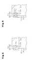
Fig. 5 is an enlarged cross-sectional view showing a sealing member of a further embodiment before a rubber portion elastically deforms; -
Fig. 6 is an enlarged cross-sectional view showing a sealing member of yet another embodiment before a rubber portion elastically deforms; and -
Fig. 7 is an enlarged cross-sectional view showing a conventional scroll compressor. - Referring to
Figs. 1 to 3 , one embodiment of a scroll compressor (hereinafter referred to as the compressor) will now be described. The compressor is installed in a vehicle and used with a vehicle air-conditioning device. - As shown in
Fig. 1 , ascroll compressor 10 includes a housing 11 made of metal (aluminum in the present embodiment). The housing 11 includes a cylindricalmotor housing member 12 and a cylindricaldischarge housing member 13. Themotor housing member 12 includes a closed end and anopen end 12h (left end as viewed inFig. 1 ). Thedischarge housing member 13, which has a closed end, is connected to theopen end 12h of themotor housing member 12. Themotor housing member 12 accommodates a compression unit P, which compresses refrigerant, and an electric motor M, which drives the compression unit P. - The
motor housing member 12 includes anend portion 12e and a cylindricalshaft support portion 12a projecting from the central section of theend portion 12e. Theshaft support portion 12a is formed integrally with theend portion 12e. Acylindrical partition 21 is fixed in themotor housing member 12 near theopen end 12h. Thepartition 21 includes aninsertion hole 21 a that extends through the central section of thepartition 21. Thepartition 21 divides themotor housing member 12 into amotor chamber 121, which accommodates the electric motor M, and an accommodation portion P1, which accommodates the compression unit P. Themotor chamber 121 is located between thepartition 21 and theend portion 12e, and the accommodation portion P1 is located between thepartition 21 and theopen end 12h. - The
motor housing member 12 also accommodates arotation shaft 20. Therotation shaft 20 includes two ends. One end, which faces toward theopen end 12h of themotor housing member 12, is located in theinsertion hole 21 a of thepartition 21 and supported by a bearing B1 to be rotatable relative to thepartition 21. The other end of therotation shaft 20 faces toward theend portion 12e of themotor housing member 12 and is supported by a bearing B2 to be rotatable relative to theshaft support portion 12a. Ashaft sealing member 20s is arranged between thepartition 21 and therotation shaft 20. - The electric motor M includes a
rotor 16, which rotates integrally with therotation shaft 20, and astator 17, which surrounds therotor 16 and is fixed to the inner surface of themotor housing member 12. When thestator 17 is supplied with power, therotor 16 and therotation shaft 20 rotate integrally. - The compression unit P includes a fixed
scroll 22 and amovable scroll 23. The fixedscroll 22 includes a circular fixedbase plate 22a, a cylindricalperipheral wall 22b projecting from the periphery of the fixedbase plate 22a, and a fixedspiral wall 22c projecting from the fixedbase plate 22a at the inner side of theperipheral wall 22b. The fixedscroll 22 is fitted into and fixed to themotor housing member 12. - The
movable scroll 23 includes a circularmovable base plate 23a and amovable spiral wall 23b projecting from themovable base plate 23a toward the fixedbase plate 22a. Themovable scroll 23 is arranged between thepartition 21 and the fixedscroll 22. Themovable scroll 23 is supported in a manner allowing for themovable scroll 23 to orbit with respect to the fixedscroll 22. - The fixed
spiral wall 22c and themovable spiral wall 23b are engaged with each other. The fixedspiral wall 22c has a distal surface that is in contact with themovable base plate 23a. Themovable spiral wall 23b has a distal surface that is in contact with the fixedbase plate 22a. The fixedbase plate 22a, the fixedspiral wall 22c, themovable base plate 23a, and themovable spiral wall 23b define acompression chamber 25. That is, thecompression chamber 25 is formed between the fixedscroll 22 and themovable scroll 23. - An
eccentric shaft 20a projects from the end surface of therotation shaft 20 that faces toward theopen end 12h. Theeccentric shaft 20a is eccentric to the rotation axis L of therotation shaft 20. Theeccentric shaft 20a is fitted into and fixed to abushing 20b. Themovable base plate 23a is supported by thebushing 20b to be rotatable relative thebushing 20b. A bearing B3 is arranged between themovable base plate 23a and thebushing 20b. - A
rotation restriction mechanism 27 is arranged between themovable base plate 23a and thepartition 21. Therotation restriction mechanism 27 includes a plurality ofcircular holes 27a, which are arranged in the outer circumferential portion of anend surface 231 a of themovable base plate 23a that faces thepartition 21, and a plurality ofcylindrical pins 27b (only one shown inFig. 1 ), which project from the outer circumferential portion of the end surface of thepartition 21 that faces themovable base plate 23a. Thepins 27b are loosely fitted into thecircular holes 27a. - When the
rotation shaft 20 is driven by the electric motor M and rotated, themovable scroll 23, which is coupled to therotation shaft 20 by theeccentric shaft 20a, orbits about the axis of the fixed scroll 22 (the rotation axis L of the rotation shaft 20). Therotation restriction mechanism 27 prevents rotation of themovable scroll 23 while permitting the orbital motion. The orbital motion of themovable scroll 23 reduces the volume of thecompression chamber 25. - The
peripheral wall 22b of the fixedscroll 22 and the outermost portion in themovable spiral wall 23b of themovable scroll 23 define asuction chamber 31 that is in communication with thecompression chamber 25. Theperipheral wall 22b of the fixedscroll 22 has an outer surface including arecess 221 b. The area surrounded by therecess 221b and the inner surface of themotor housing member 12 forms asuction passage 32 that is connected to thesuction chamber 31 through a throughhole 221 h in theperipheral wall 22b of the fixedscroll 22. A throughhole 21 1 , which extends through the peripheral portion of thepartition 21 connects thesuction passage 32 to themotor chamber 121. - The
motor housing member 12 includes asuction port 122. Thesuction port 122 is connected to an external refrigerant circuit (not shown). Refrigerant (gas) is drawn into themotor chamber 121 from the external refrigerant circuit through thesuction port 122. The refrigerant in themotor chamber 121 is then sent to thecompression chamber 25 through the throughhole 211, thesuction passage 32, the throughhole 221 h, and thesuction chamber 31. Thus, themotor chamber 121, the throughhole 21 1 , thesuction passage 32, the throughhole 221 h, and thesuction chamber 31 form a suction pressure region. - The refrigerant in the
compression chamber 25 is compressed by the orbiting motion (discharging motion) of themovable scroll 23 and discharged into adischarge chamber 131 of thedischarge housing member 13 through adischarge port 22e by forcibly opening adischarge valve 22v. The refrigerant is then discharged to the external refrigerant circuit through adischarge port 132 formed in thedischarge housing member 13. Thus, thedischarge chamber 131 forms a discharge pressure region. - The area surrounding the
rotation shaft 20 between themovable scroll 23 and thepartition 21 forms aback pressure chamber 35. Theback pressure chamber 35 is in communication with thecircular holes 27a. Further, themovable scroll 23 includes aninlet 36, which opens in the distal surface of themovable spiral wall 23b, anoutlet 37, which opens in theback pressure chamber 35, and acommunication passage 38, which communicates theinlet 36 and theoutlet 37. When the pressure in thecompression chamber 25 excessively increases and moves the distal surface of themovable spiral wall 23b away from the fixedbase plate 22a, the compressed refrigerant in thecompression chamber 25 flows into theinlet 36 through the gap between the distal surface of themovable spiral wall 23b and the fixedbase plate 22a. The refrigerant then flows through thecommunication passage 38 and theoutlet 37 into theback pressure chamber 35 and thecircular holes 27a. This increases the pressure (back pressure) in theback pressure chamber 35 and thecircular holes 27a. The back pressure produces an urging force that urges themovable scroll 23 toward the fixedscroll 22. In the present embodiment, theback pressure chamber 35 and thecircular holes 27a form a back pressure region that produces the urging force urging themovable scroll 23 toward the fixedscroll 22 when the refrigerant flows into theback pressure chamber 35 and thecircular holes 27a. Thepartition 21 serves as an opposing wall that defines the back pressure region between themovable scroll 23 and the opposing wall. - A
bleed passage 40 extending through thepartition 21 connects themotor chamber 121 to theback pressure chamber 35 and thecircular holes 27a. A regulatingvalve 41 is arranged in thebleed passage 40 to regulate the open degree of thebleed passage 40 in accordance with the difference between the pressure in themotor chamber 121 and the back pressure in theback pressure chamber 35 and thecircular holes 27a. The regulatingvalve 41 is operated to maintain a constant difference between the pressure in themotor chamber 121 and the back pressure in theback pressure chamber 35 and thecircular holes 27a. Thus, during normal operation of thescroll compressor 10, the regulatingvalve 41 functions to keep constant the back pressure in theback pressure chamber 35 and thecircular holes 27a and, consequently, the urging force of themovable scroll 23 produced by the back pressure. - As shown in
Fig. 2 , theend surface 231 a of themovable scroll 23 includes agroove 50 that serves as a holding portion. Thegroove 50 is located at a position separated from the outer circumferential surface of themovable scroll 23. Thegroove 50 is annular and located at the radially outer side of thecircular holes 27a in theend surface 231 a of themovable scroll 23. Thegroove 50 receives anannular sealing member 51. - As shown in
Fig. 2A , the sealingmember 51 includes arubber portion 53, which elastically deforms in thegroove 50, and aresin portion 52, which is made of a material harder than therubber portion 53. Therubber portion 53 may be made of hydrogenated nitrile butadiene rubber (HNBR), ethylene propylene rubber (EPM, EPDM), or chloroprene rubber (CR), for example. Preferably, therubber portion 53 may be made of HNBR. Theresin portion 52 may be made of polytetrafluoroethylene (PTFE), for example. Theresin portion 52 is formed integrally with therubber portion 53. Theresin portion 52 is located between therubber portion 53 and thepartition 21. Theresin portion 52 partially projects out of thegroove 50 toward thepartition 21. Theresin portion 52 includes aflat surface 52a that faces thepartition 21 and is in planer contact with thepartition 21. -
Fig. 3 shows the sealingmember 51 before therubber portion 53 elastically deforms. Therubber portion 53 is tapered so that the diameter becomes smaller at locations farther from theresin portion 52. Since the radial width of therubber portion 53 varies in the axial length of therubber portion 53, therubber portion 53 partially has a smaller radial width than theresin portion 52. As shown inFig. 2A , a space is formed between the outer surface of therubber portion 53 and the wall surface of thegroove 50. The space allows therubber portion 53 to elastically deform in thegroove 50. Therubber portion 53 includes a flatdistal end 53a in contact with anend portion 50a of thegroove 50. The sealingmember 51 is held in thegroove 50 with therubber portion 53 elastically deformed in thegroove 50. - The operation of the present embodiment will now be described.
- The back pressure in the
back pressure chamber 35 and thecircular holes 27a is insufficient when thescroll compressor 10 starts to operate. The sealingmember 51 is held in thegroove 50 with therubber portion 53 elastically deformed in thegroove 50. Thedeformed rubber portion 53 produces a resilient force that acts to restore the original shape of therubber portion 53. This urges themovable scroll 23 toward the fixedscroll 22 and enhances the sealing of thecompression chamber 25. - Further, when the pressure in the
compression chamber 25 excessively increases and moves the distal surface of themovable spiral wall 23b away from the fixedbase plate 22a, the compressed refrigerant in thecompression chamber 25 flows into theinlet 36 through the gap between the distal surface of themovable spiral wall 23b and the fixedbase plate 22a. The refrigerant then flows through thecommunication passage 38 and theoutlet 37 into theback pressure chamber 35 and thecircular holes 27a. This increases the back pressure in theback pressure chamber 35 and thecircular holes 27a. The urging force caused by the back pressure in theback pressure chamber 35 and thecircular holes 27a urges themovable scroll 23 to the fixedscroll 22 and moves the distal surface of themovable spiral wall 23b into contact with the fixedbase plate 22a. Accordingly, the distal surface of themovable spiral wall 23b is pressed against the fixedscroll 22. This enhances the sealing of thecompression chamber 25. In this manner, the urging of themovable scroll 23 relative to the fixedscroll 22 is controlled. - If the
movable scroll 23 were urged toward the fixedscroll 22 by an urging force produced by the elastic deformation of a metal sealing member like in the prior art, it would be difficult to control the urging of themovable scroll 23 relative to the fixedscroll 22. This may cause a mechanical loss. In the present embodiment, the urging force that is produced by the elastic deformation of therubber portion 53 and presses themovable scroll 23 against the fixedscroll 22 is smaller than the urging force produced by the elastic deformation of the conventional metal sealing member. This allows for the urging of themovable scroll 23 relative to the fixedscroll 22 to be easily controlled and limits mechanical loss. - The contact between the
surface 52a of theresin portion 52 and thepartition 21 seals theback pressure chamber 35 and thecircular holes 27a from the region (suction pressure region) in themotor housing member 12 that is located at the outer side of theback pressure chamber 35 and thecircular holes 27a. This effectively restricts leakage of refrigerant from theback pressure chamber 35 and thecircular holes 27a as compared to when sealing theback pressure chamber 35 and thecircular holes 27a from the outer region with the metal sealing member of the prior art. - The
resin portion 52 partially projects out of thegroove 50 toward thepartition 21 , and thesurface 52a of theresin portion 52 is in contact with thepartition 21. Thus, even when the pressure in thecompression chamber 25 excessively increases and moves themovable scroll 23 toward thepartition 21, theresin portion 52 restricts contact of theend surface 231 a of themovable scroll 23 with thepartition 21. This reduces the sliding resistance between themovable scroll 23 and thepartition 21, thereby limiting mechanical loss. - The advantages of the present embodiment will now be described.
- (1) The
end surface 231 a of themovable scroll 23 includes thegroove 50 that holds the sealingmember 51. The sealingmember 51 includes therubber portion 53, which elastically deforms in thegroove 50, and theresin portion 52, which is made of a material harder than therubber portion 53. Further, theresin portion 52 partially projects out of thegroove 50 toward thepartition 21. Theresin portion 52 is in contact with thepartition 21, which seals theback pressure chamber 35 and thecircular holes 27a. This effectively restricts the leakage of refrigerant from theback pressure chamber 35 and thecircular holes 27a as compared to when sealing theback pressure chamber 35 and thecircular holes 27a with a metal sealing member like in the prior art. Further, the elasticallydeformed rubber portion 53 produces resilient force that acts to restore the original shape of therubber portion 53 and urge themovable scroll 23 toward the fixedscroll 22. Thus, themovable scroll 23 is urged toward the fixedscroll 22 even when the back pressure in theback pressure chamber 35 and thecircular holes 27a is insufficient, such as when thescroll compressor 10 starts to operate. This enhances the sealing of thecompression chamber 25.
During normal operation of thescroll compressor 10, themovable scroll 23 is urged toward the fixedscroll 22 by the urging force produced by the elastic deformation of therubber portion 53, as well as the urging force produced by the back pressure in theback pressure chamber 35 and thecircular holes 27a. Thus, even when the urging force of the back pressure in theback pressure chamber 35 and thecircular holes 27a sufficiently urges themovable scroll 23 toward the fixedscroll 22 and securely seals thecompression chamber 25, the urging force produced by the elastic deformation of therubber portion 53 also urges themovable scroll 23 toward the fixedscroll 22. However, the urging force of the elastic deformation of therubber portion 53 that presses themovable scroll 23 against the fixedscroll 22 is smaller than the urging force produced by the elastic deformation of the conventional metal sealing member. This limits mechanical loss. - (2) The
rubber portion 53 partially has a smaller radial width than theresin portion 52. This forms a space in thegroove 50 that allows for the elastic deformation of therubber portion 53. Thus, therubber portion 53 can easily deform in thegroove 50. - (3) The
resin portion 52 and therubber portion 53 of the sealingmember 51 are integrally formed. This allows for the sealingmember 51 to be easily held in thegroove 50 compared to when theresin portion 52 and therubber portion 53 are discrete from each other. In addition, sealing is ensured between theresin portion 52 and therubber portion 53. - (4) The
groove 50 is arranged in theend surface 231 a of themovable scroll 23 at a position separated from the outer circumferential surface of themovable scroll 23. This ensures the holding of the sealingmember 51 compared to when the sealingmember 51 were held in a cut out portion formed in theend surface 231 a and opening in the outer circumferential surface of themovable scroll 23, for example. - (5) The
movable scroll 23 includes theinlet 36, which opens in the distal surface of themovable spiral wall 23b, theoutlet 37, which opens to theback pressure chamber 35 and thecircular holes 27a, and thecommunication passage 38, which communicates theinlet 36 and theoutlet 37. Thus, when the pressure in thecompression chamber 25 excessively increases and moves the distal surface of themovable spiral wall 23b away from the fixedbase plate 22a, the compressed refrigerant in thecompression chamber 25 flows into theinlet 36 through the gap between the distal surface of themovable spiral wall 23b and the fixedbase plate 22a. The refrigerant then flows through thecommunication passage 38 and theoutlet 37 into theback pressure chamber 35 and thecircular holes 27a. This increases the back pressure in theback pressure chamber 35 and thecircular holes 27a. The urging force produced by the back pressure in theback pressure chamber 35 and thecircular holes 27a urges themovable scroll 23 to the fixedscroll 22 and moves the distal surface of themovable spiral wall 23b into contact with the fixedbase plate 22a. Accordingly, the distal surface of themovable spiral wall 23b is pressed against the fixedscroll 22. This enhances the sealing of thecompression chamber 25. In this manner, the urging of themovable scroll 23 relative to the fixedscroll 22 is controlled. If themovable scroll 23 were urged toward the fixedscroll 22 by the urging force produced by the elastic deformation of a metal sealing member like in the prior art, the urging of themovable scroll 23 relative to the fixedscroll 22 would be difficult to control adequately. This may cause a mechanical loss. In the present embodiment, the urging force produced by the elastic deformation of therubber portion 53 that presses themovable scroll 23 against the fixedscroll 22 is smaller than the urging force produced by the elastic deformation of the conventional metal sealing member. This allows for easy control of the urging of themovable scroll 23 relative to the fixedscroll 22 and limits mechanical loss. - (6) The
resin portion 52 of the sealingmember 51 faces thepartition 21. This increases the wear resistance of the sealingmember 51 that slides on thepartition 21 when themovable scroll 23 orbits as compared to when a rubber portion of the sealingmember 51 faces toward thepartition 21. - (7) The present embodiment does not include a metal sealing member like in the prior art. This eliminates the need for a recess in the
partition 21 to allow for elastic deformation of the metal sealing member and facilitates the manufacturing of thepartition 21. - (8) The
resin portion 52 includes a flat surface that faces thepartition 21. This allows for planer contact between thesurface 52a of theresin portion 52 and thepartition 21. Thus, the area of contact between theresin portion 52 and thepartition 21 is enlarged compared to when theresin portion 52 and thepartition 21 are in liner contact (or point contact). This enhances the sealing of theback pressure chamber 35 and thecircular holes 27a from the region of themotor housing member 12 located at the outer side of theback pressure chamber 35 and thecircular holes 27a. - (9) The
resin portion 52 partially projects out of thegroove 50 toward thepartition 21 , and thesurface 52a of theresin portion 52 is in contact with thepartition 21. Thus, even when the pressure in thecompression chamber 25 excessively increases and moves themovable scroll 23 toward thepartition 21, contact of theend surface 231 a of themovable scroll 23 with thepartition 21 is restricted. This reduces the sliding resistance between themovable scroll 23 and thepartition 21, and limits mechanical loss. - It should be apparent to those skilled in the art that the present invention may be embodied in many other specific forms without departing from the spirit or scope of the invention. Particularly, it should be understood that the present invention may be embodied in the following forms.
- As shown in
Fig. 4 , theend surface 231 a of themovable scroll 23 may include a cut outportion 60, which serves as a holding portion. The cut outportion 60 opens in the outer circumferential surface of themovable scroll 23. The cut outportion 60 is easier to form in themovable scroll 23 than a recess formed in theend surface 231 a at a position separated from the outer circumferential surface of themovable scroll 23. - As shown in
Fig. 5 , anannular sealing member 51 A may include anannular resin portion 52A and anannular rubber portion 53A, which extends from an end surface of theresin portion 52A. Therubber portion 53A may include inner and outer surfaces extending perpendicular to the end surface of theresin portion 52A. Therubber portion 53A has a larger inner diameter than theresin portion 52A and a smaller outer diameter than theresin portion 52A. In this manner, the width of therubber portion 53A in the radial direction is smaller than that of theresin portion 52A along entire axial dimension of therubber portion 53A. - As shown in
Fig. 6 , theresin portion 52A may include afitting groove 521 A in the end surface facing therubber portion 53A. Therubber portion 53A may be fitted into thefitting groove 521 A. This enhances the connection and the sealing between theresin portion 52A and therubber portion 53A. - The
rubber portion 53 and theresin portion 52 may have the same radial width. - The
resin portion 52 may have a curved surface that faces thepartition 21. This allows for theresin portion 52 and thepartition 21 to be in linear contact (or point contact). - The
resin portion 52 may entirely project out of thegroove 50 toward thepartition 21. - The
resin portion 52 and therubber portion 53 may be discrete from each other. In this case, it is preferable that theresin portion 52 and therubber portion 53 are fitted to each other as shown inFig. 6 , for example, to secure the connection and the sealing between theresin portion 52 and therubber portion 53. - The
back pressure chamber 35 and thecircular holes 27a may be supplied with refrigerant from the discharge region. - The present examples and embodiments are to be considered as illustrative and not restrictive and the invention is not to be limited to the details given herein, but may be modified within the scope and equivalence of the appended claims.
- A scroll compressor includes a housing, a fixed scroll, and a movable scroll. A compression chamber is formed between the movable scroll and the fixed scroll. An opposing wall is located in and fixed to the housing. A back pressure region is formed between the opposing wall and the movable scroll, and a back pressure in the back pressure region urges the movable scroll toward the fixed scroll. An annular sealing member is arranged between the movable scroll and the opposing wall. The movable scroll includes a holding portion that holds the sealing member. The sealing member includes a rubber portion, which elastically deforms in the holding portion, and a resin portion, which is made of a material harder than the rubber portion. The resin portion at least partially projects out of the holding portion toward the opposing wall. The resin portion is in contact with the opposing wall.
Claims (8)
- A scroll compressor (10) comprising:a housing (11);a fixed scroll (22) located in and fixed to the housing (11);a movable scroll (23) that orbits with respect to the fixed scroll (22), wherein a compression chamber (25) is formed between the movable scroll (23) and the fixed scroll (22);an opposing wall (21) located in and fixed to the housing (11), wherein a back pressure region (35) is formed between the opposing wall (21) and the movable scroll (23), and a back pressure in the back pressure region (35) urges the movable scroll (23) toward the fixed scroll (22); andan annular sealing member (51, 51A) arranged between the movable scroll (23) and the opposing wall (21),the scroll compressor (10) being characterized in thatthe movable scroll (23) includes an end surface (231 a) that faces the opposing wall (21) and includes a holding portion (50, 60), wherein the holding portion (50, 60) holds the sealing member (51, 51A),the sealing member (51, 51A) includes a rubber portion (53, 53A), which elastically deforms in the holding portion (50, 60), and a resin portion (52, 52A), which is made of a material harder than the rubber portion (53, 53A),the resin portion (52, 52A) at least partially projects out of the holding portion (50, 60) toward the opposing wall (21), andthe resin portion (52, 52A) is in contact with the opposing wall (21).
- The scroll compressor (10) according to claim 1 , wherein the rubber portion (53, 53A) at least partially has a smaller radial width than the resin portion (52, 52A).
- The scroll compressor (10) according to claim 1 or 2, wherein the resin portion (52, 52A) and the rubber portion (53, 53A) are integrally formed.
- The scroll compressor (10) according to claim 1 or 2, wherein
the resin portion (52A) and the rubber portion (53A) are discrete from each other, and
the resin portion (52A) includes a groove (521 A) into which the rubber portion (53A) is fitted. - The scroll compressor (10) according to any one of claims 1 to 4, wherein the holding portion (50) is a groove (50) located at a position separated from an outer circumferential surface of the movable scroll (23).
- The scroll compressor (10) according to any one of claims 1 to 4, wherein the holding portion (60) is a cut out portion (60) that opens in an outer circumferential surface of the movable scroll (23).
- The scroll compressor (10) according to any one of claims 1 to 6, wherein
the fixed scroll (22) includes a fixed base plate (22a) and a fixed spiral wall (22c) projecting from the fixed base plate (22a),
the movable scroll (23) includes a movable base plate (23a) and a movable spiral wall (23b) projecting from the movable base plate (23a),
the fixed spiral wall (22c) and the movable spiral wall (23b) are engaged with each other to define the compression chamber (25), and
the movable scroll (23) includesan inlet (36) that opens in a distal surface of the movable spiral wall (23b),an outlet (37) that opens in the back pressure region (35), anda communication passage (38) that communicates the inlet (36) and the outlet (37). - The scroll compressor (10) according to any one of claims 1 to 7, wherein the resin portion (52, 52A) includes a flat surface (52a) that is in contact with the opposing wall (21).
Applications Claiming Priority (1)
| Application Number | Priority Date | Filing Date | Title |
|---|---|---|---|
| JP2013041915A JP5817760B2 (en) | 2013-03-04 | 2013-03-04 | Scroll compressor |
Publications (3)
| Publication Number | Publication Date |
|---|---|
| EP2799665A2 true EP2799665A2 (en) | 2014-11-05 |
| EP2799665A3 EP2799665A3 (en) | 2015-04-29 |
| EP2799665B1 EP2799665B1 (en) | 2017-04-05 |
Family
ID=50238135
Family Applications (1)
| Application Number | Title | Priority Date | Filing Date |
|---|---|---|---|
| EP14156956.6A Active EP2799665B1 (en) | 2013-03-04 | 2014-02-27 | Scroll compressor |
Country Status (7)
| Country | Link |
|---|---|
| US (1) | US9243639B2 (en) |
| EP (1) | EP2799665B1 (en) |
| JP (1) | JP5817760B2 (en) |
| KR (1) | KR101606627B1 (en) |
| CN (1) | CN104033383B (en) |
| DE (1) | DE202014010988U1 (en) |
| PT (1) | PT2799665T (en) |
Cited By (1)
| Publication number | Priority date | Publication date | Assignee | Title |
|---|---|---|---|---|
| EP3683444A1 (en) * | 2019-01-18 | 2020-07-22 | LG Electronics Inc. | Motor operated compressor |
Families Citing this family (18)
| Publication number | Priority date | Publication date | Assignee | Title |
|---|---|---|---|---|
| KR102040967B1 (en) * | 2014-10-13 | 2019-11-06 | 한온시스템 주식회사 | Back pressure control apparatus of compressor |
| BE1023333B1 (en) * | 2015-04-09 | 2017-02-07 | Atlas Copco Airpower, N.V. | Spiral type device and method for the production of such device and seal for such device |
| WO2016161488A2 (en) * | 2015-04-09 | 2016-10-13 | Atlas Copco Airpower, Naamloze Vennootschap | Scroll type apparatus and method for manufacturing such a scroll type apparatus and seal for such a scroll type apparatus |
| JP2017172427A (en) * | 2016-03-23 | 2017-09-28 | サンデン・オートモーティブコンポーネント株式会社 | Scroll-type compressor |
| JP2018031281A (en) * | 2016-08-24 | 2018-03-01 | サンデンホールディングス株式会社 | Scroll type compressor |
| DE102017206172A1 (en) * | 2017-04-11 | 2018-10-11 | Robert Bosch Gmbh | Scroll expansion machine and exhaust residual heat utilization device, in particular a vehicle, with such an expansion machine |
| JP6753355B2 (en) | 2017-05-16 | 2020-09-09 | 株式会社デンソー | Scroll compressor |
| US10701866B2 (en) * | 2017-10-25 | 2020-07-07 | Deere & Company | Drive system for intermittent rotation output |
| JP2019178676A (en) * | 2018-03-30 | 2019-10-17 | 株式会社豊田自動織機 | Scroll type compressor |
| JP6947106B2 (en) * | 2018-03-30 | 2021-10-13 | 株式会社豊田自動織機 | Scroll compressor |
| JP6943215B2 (en) | 2018-03-30 | 2021-09-29 | 株式会社豊田自動織機 | Electric compressor |
| DE102018110025B4 (en) * | 2018-04-26 | 2020-06-04 | OET GmbH | Displacement machine |
| DE102019200507A1 (en) * | 2019-01-16 | 2020-07-16 | Brose Fahrzeugteile SE & Co. Kommanditgesellschaft, Würzburg | Scroll compressor for a vehicle air conditioning system |
| KR102718495B1 (en) * | 2019-09-04 | 2024-10-16 | 현대모비스 주식회사 | Apparatus for a Formation of Back-Pressure in Electric Compressor and Method Employing the Same |
| JP7608236B2 (en) | 2021-03-29 | 2025-01-06 | 三菱重工サーマルシステムズ株式会社 | Scroll Fluid Machine |
| CN217300900U (en) * | 2022-04-29 | 2022-08-26 | 罗伯特·博世有限公司 | Movable scroll and scroll compressor |
| CN116857180A (en) * | 2022-06-01 | 2023-10-10 | 杭州绿能新能源汽车部件有限公司 | Scroll compressor having a rotor with a rotor shaft having a rotor shaft with a |
| US12577951B2 (en) | 2024-03-19 | 2026-03-17 | Mahle International Gmbh | Electric compressor with scroll backpressure system |
Citations (1)
| Publication number | Priority date | Publication date | Assignee | Title |
|---|---|---|---|---|
| JP2004144045A (en) | 2002-10-25 | 2004-05-20 | Toyota Industries Corp | Scroll compressor |
Family Cites Families (19)
| Publication number | Priority date | Publication date | Assignee | Title |
|---|---|---|---|---|
| US3663024A (en) * | 1970-07-02 | 1972-05-16 | Shamban & Co W S | Sealing assembly |
| GB1550293A (en) * | 1976-11-22 | 1979-08-08 | Caterpillar Tractor Co | Shaft seal |
| JPS60252184A (en) | 1984-05-29 | 1985-12-12 | Toshiba Corp | Scroll compressor |
| JPH0712700Y2 (en) * | 1988-05-25 | 1995-03-29 | ダイキン工業株式会社 | Sealing structure for rotary fluid equipment |
| JPH0377685A (en) | 1989-08-17 | 1991-04-03 | Mitsui Toatsu Chem Inc | Treatment of aqueous solution containing formaldehyde with membrane |
| JPH0558885U (en) | 1992-01-16 | 1993-08-03 | 株式会社神戸製鋼所 | Scroll compressor |
| JP3584533B2 (en) | 1995-04-12 | 2004-11-04 | 株式会社日立製作所 | Scroll compressor |
| JPH09177685A (en) * | 1995-12-27 | 1997-07-11 | Daikin Ind Ltd | Scroll type fluid machine |
| JP3422747B2 (en) * | 2000-03-06 | 2003-06-30 | アネスト岩田株式会社 | Scroll fluid machine |
| JP3516160B2 (en) | 2000-05-26 | 2004-04-05 | アネスト岩田株式会社 | Seal structure in scroll fluid machine and scroll fluid machine |
| JP2002054583A (en) * | 2000-08-16 | 2002-02-20 | Mitsubishi Heavy Ind Ltd | Scroll type fluid machine |
| US6695599B2 (en) * | 2001-06-29 | 2004-02-24 | Nippon Soken, Inc. | Scroll compressor |
| JP2005320885A (en) * | 2004-05-07 | 2005-11-17 | Anest Iwata Corp | Dust seal in scroll fluid machine |
| JP2007231796A (en) * | 2006-02-28 | 2007-09-13 | Anest Iwata Corp | Tip seal for scroll fluid machine |
| JP4951572B2 (en) | 2008-03-31 | 2012-06-13 | 日立アプライアンス株式会社 | Scroll compressor |
| JP5291423B2 (en) * | 2008-10-01 | 2013-09-18 | サンデン株式会社 | Fluid machinery |
| JP5201113B2 (en) | 2008-12-03 | 2013-06-05 | 株式会社豊田自動織機 | Scroll compressor |
| JP2011027076A (en) * | 2009-07-29 | 2011-02-10 | Panasonic Corp | Scroll compressor |
| JP2012017656A (en) * | 2010-07-06 | 2012-01-26 | Sanden Corp | Scroll compressor |
-
2013
- 2013-03-04 JP JP2013041915A patent/JP5817760B2/en active Active
-
2014
- 2014-02-27 KR KR1020140023611A patent/KR101606627B1/en active Active
- 2014-02-27 DE DE202014010988.5U patent/DE202014010988U1/en not_active Expired - Lifetime
- 2014-02-27 EP EP14156956.6A patent/EP2799665B1/en active Active
- 2014-02-27 PT PT141569566T patent/PT2799665T/en unknown
- 2014-02-28 US US14/193,801 patent/US9243639B2/en active Active
- 2014-02-28 CN CN201410073363.8A patent/CN104033383B/en active Active
Patent Citations (1)
| Publication number | Priority date | Publication date | Assignee | Title |
|---|---|---|---|---|
| JP2004144045A (en) | 2002-10-25 | 2004-05-20 | Toyota Industries Corp | Scroll compressor |
Cited By (1)
| Publication number | Priority date | Publication date | Assignee | Title |
|---|---|---|---|---|
| EP3683444A1 (en) * | 2019-01-18 | 2020-07-22 | LG Electronics Inc. | Motor operated compressor |
Also Published As
| Publication number | Publication date |
|---|---|
| PT2799665T (en) | 2017-04-24 |
| KR20140109289A (en) | 2014-09-15 |
| DE202014010988U1 (en) | 2017-03-10 |
| JP2014169665A (en) | 2014-09-18 |
| CN104033383A (en) | 2014-09-10 |
| KR101606627B1 (en) | 2016-03-25 |
| CN104033383B (en) | 2017-04-12 |
| JP5817760B2 (en) | 2015-11-18 |
| US9243639B2 (en) | 2016-01-26 |
| US20140248172A1 (en) | 2014-09-04 |
| EP2799665B1 (en) | 2017-04-05 |
| EP2799665A3 (en) | 2015-04-29 |
Similar Documents
| Publication | Publication Date | Title |
|---|---|---|
| EP2799665B1 (en) | Scroll compressor | |
| KR102191123B1 (en) | Motor operated compressor | |
| US9784271B2 (en) | Scroll compressor | |
| EP2781753A1 (en) | Scroll compressor with back pressure discharge | |
| US9181951B2 (en) | Scroll compressor | |
| US9732752B2 (en) | Scroll compressor having a back pressure chamber assembly disposed on a fixed scroll plate and an elastic member disposed between a floating plate and a discharge cover | |
| EP2589808A1 (en) | Scroll compressor | |
| EP2618000B1 (en) | Differential pressure regulating valve and motor-driven compressor having differential pressure regulating device | |
| US11168688B2 (en) | Scroll compressor | |
| CN110360101B (en) | Compressor with bushing | |
| CN109844318B (en) | Scroll compressor having a plurality of scroll members | |
| CN103790636A (en) | Flanged sleeve guide | |
| US10941773B2 (en) | Scroll compressor | |
| US8029254B2 (en) | Scroll-type fluid machine having a back-pressure chamber | |
| US20170268511A1 (en) | Scroll compressor | |
| US11008867B2 (en) | Scroll compressor with wear-resistant members | |
| US10697455B2 (en) | Compressor having lubrication structure for thrust surface | |
| KR20080084220A (en) | Rotary compressor | |
| EP2781752B1 (en) | Scroll compressor having a scroll support and/or movement limiter | |
| EP1087141A2 (en) | Scroll-type compressor | |
| EP3726058A1 (en) | Motor operated compressor | |
| JP2009047089A (en) | Scroll type fluid machine | |
| JP2006077732A (en) | Scroll compressor |
Legal Events
| Date | Code | Title | Description |
|---|---|---|---|
| REG | Reference to a national code |
Ref country code: DE Ref legal event code: R138 Ref document number: 202014010988 Country of ref document: DE Free format text: GERMAN DOCUMENT NUMBER IS 602014008212 |
|
| PUAI | Public reference made under article 153(3) epc to a published international application that has entered the european phase |
Free format text: ORIGINAL CODE: 0009012 |
|
| 17P | Request for examination filed |
Effective date: 20140227 |
|
| AK | Designated contracting states |
Kind code of ref document: A2 Designated state(s): AL AT BE BG CH CY CZ DE DK EE ES FI FR GB GR HR HU IE IS IT LI LT LU LV MC MK MT NL NO PL PT RO RS SE SI SK SM TR |
|
| AX | Request for extension of the european patent |
Extension state: BA ME |
|
| PUAL | Search report despatched |
Free format text: ORIGINAL CODE: 0009013 |
|
| AK | Designated contracting states |
Kind code of ref document: A3 Designated state(s): AL AT BE BG CH CY CZ DE DK EE ES FI FR GB GR HR HU IE IS IT LI LT LU LV MC MK MT NL NO PL PT RO RS SE SI SK SM TR |
|
| AX | Request for extension of the european patent |
Extension state: BA ME |
|
| RIC1 | Information provided on ipc code assigned before grant |
Ipc: F01C 19/00 20060101AFI20150324BHEP Ipc: F04C 23/00 20060101ALN20150324BHEP Ipc: F04C 18/02 20060101ALI20150324BHEP Ipc: F04C 27/00 20060101ALI20150324BHEP |
|
| 17Q | First examination report despatched |
Effective date: 20150410 |
|
| GRAP | Despatch of communication of intention to grant a patent |
Free format text: ORIGINAL CODE: EPIDOSNIGR1 |
|
| RIC1 | Information provided on ipc code assigned before grant |
Ipc: F04C 23/00 20060101ALN20160916BHEP Ipc: F04C 18/02 20060101ALI20160916BHEP Ipc: F04C 27/00 20060101ALI20160916BHEP Ipc: F01C 19/00 20060101AFI20160916BHEP |
|
| INTG | Intention to grant announced |
Effective date: 20161019 |
|
| GRAS | Grant fee paid |
Free format text: ORIGINAL CODE: EPIDOSNIGR3 |
|
| GRAA | (expected) grant |
Free format text: ORIGINAL CODE: 0009210 |
|
| AK | Designated contracting states |
Kind code of ref document: B1 Designated state(s): AL AT BE BG CH CY CZ DE DK EE ES FI FR GB GR HR HU IE IS IT LI LT LU LV MC MK MT NL NO PL PT RO RS SE SI SK SM TR |
|
| REG | Reference to a national code |
Ref country code: GB Ref legal event code: FG4D |
|
| REG | Reference to a national code |
Ref country code: CH Ref legal event code: EP |
|
| REG | Reference to a national code |
Ref country code: AT Ref legal event code: REF Ref document number: 882024 Country of ref document: AT Kind code of ref document: T Effective date: 20170415 |
|
| REG | Reference to a national code |
Ref country code: PT Ref legal event code: SC4A Ref document number: 2799665 Country of ref document: PT Date of ref document: 20170424 Kind code of ref document: T Free format text: AVAILABILITY OF NATIONAL TRANSLATION Effective date: 20170411 |
|
| REG | Reference to a national code |
Ref country code: IE Ref legal event code: FG4D |
|
| REG | Reference to a national code |
Ref country code: DE Ref legal event code: R096 Ref document number: 602014008212 Country of ref document: DE |
|
| REG | Reference to a national code |
Ref country code: NL Ref legal event code: MP Effective date: 20170405 |
|
| REG | Reference to a national code |
Ref country code: LT Ref legal event code: MG4D |
|
| REG | Reference to a national code |
Ref country code: AT Ref legal event code: MK05 Ref document number: 882024 Country of ref document: AT Kind code of ref document: T Effective date: 20170405 |
|
| PG25 | Lapsed in a contracting state [announced via postgrant information from national office to epo] |
Ref country code: NL Free format text: LAPSE BECAUSE OF FAILURE TO SUBMIT A TRANSLATION OF THE DESCRIPTION OR TO PAY THE FEE WITHIN THE PRESCRIBED TIME-LIMIT Effective date: 20170405 |
|
| PG25 | Lapsed in a contracting state [announced via postgrant information from national office to epo] |
Ref country code: GR Free format text: LAPSE BECAUSE OF FAILURE TO SUBMIT A TRANSLATION OF THE DESCRIPTION OR TO PAY THE FEE WITHIN THE PRESCRIBED TIME-LIMIT Effective date: 20170706 Ref country code: AT Free format text: LAPSE BECAUSE OF FAILURE TO SUBMIT A TRANSLATION OF THE DESCRIPTION OR TO PAY THE FEE WITHIN THE PRESCRIBED TIME-LIMIT Effective date: 20170405 Ref country code: ES Free format text: LAPSE BECAUSE OF FAILURE TO SUBMIT A TRANSLATION OF THE DESCRIPTION OR TO PAY THE FEE WITHIN THE PRESCRIBED TIME-LIMIT Effective date: 20170405 Ref country code: HR Free format text: LAPSE BECAUSE OF FAILURE TO SUBMIT A TRANSLATION OF THE DESCRIPTION OR TO PAY THE FEE WITHIN THE PRESCRIBED TIME-LIMIT Effective date: 20170405 Ref country code: LT Free format text: LAPSE BECAUSE OF FAILURE TO SUBMIT A TRANSLATION OF THE DESCRIPTION OR TO PAY THE FEE WITHIN THE PRESCRIBED TIME-LIMIT Effective date: 20170405 Ref country code: FI Free format text: LAPSE BECAUSE OF FAILURE TO SUBMIT A TRANSLATION OF THE DESCRIPTION OR TO PAY THE FEE WITHIN THE PRESCRIBED TIME-LIMIT Effective date: 20170405 Ref country code: NO Free format text: LAPSE BECAUSE OF FAILURE TO SUBMIT A TRANSLATION OF THE DESCRIPTION OR TO PAY THE FEE WITHIN THE PRESCRIBED TIME-LIMIT Effective date: 20170705 |
|
| PG25 | Lapsed in a contracting state [announced via postgrant information from national office to epo] |
Ref country code: BG Free format text: LAPSE BECAUSE OF FAILURE TO SUBMIT A TRANSLATION OF THE DESCRIPTION OR TO PAY THE FEE WITHIN THE PRESCRIBED TIME-LIMIT Effective date: 20170705 Ref country code: RS Free format text: LAPSE BECAUSE OF FAILURE TO SUBMIT A TRANSLATION OF THE DESCRIPTION OR TO PAY THE FEE WITHIN THE PRESCRIBED TIME-LIMIT Effective date: 20170405 Ref country code: SE Free format text: LAPSE BECAUSE OF FAILURE TO SUBMIT A TRANSLATION OF THE DESCRIPTION OR TO PAY THE FEE WITHIN THE PRESCRIBED TIME-LIMIT Effective date: 20170405 Ref country code: PL Free format text: LAPSE BECAUSE OF FAILURE TO SUBMIT A TRANSLATION OF THE DESCRIPTION OR TO PAY THE FEE WITHIN THE PRESCRIBED TIME-LIMIT Effective date: 20170405 Ref country code: IS Free format text: LAPSE BECAUSE OF FAILURE TO SUBMIT A TRANSLATION OF THE DESCRIPTION OR TO PAY THE FEE WITHIN THE PRESCRIBED TIME-LIMIT Effective date: 20170805 Ref country code: LV Free format text: LAPSE BECAUSE OF FAILURE TO SUBMIT A TRANSLATION OF THE DESCRIPTION OR TO PAY THE FEE WITHIN THE PRESCRIBED TIME-LIMIT Effective date: 20170405 |
|
| REG | Reference to a national code |
Ref country code: DE Ref legal event code: R097 Ref document number: 602014008212 Country of ref document: DE |
|
| PG25 | Lapsed in a contracting state [announced via postgrant information from national office to epo] |
Ref country code: DK Free format text: LAPSE BECAUSE OF FAILURE TO SUBMIT A TRANSLATION OF THE DESCRIPTION OR TO PAY THE FEE WITHIN THE PRESCRIBED TIME-LIMIT Effective date: 20170405 Ref country code: EE Free format text: LAPSE BECAUSE OF FAILURE TO SUBMIT A TRANSLATION OF THE DESCRIPTION OR TO PAY THE FEE WITHIN THE PRESCRIBED TIME-LIMIT Effective date: 20170405 Ref country code: RO Free format text: LAPSE BECAUSE OF FAILURE TO SUBMIT A TRANSLATION OF THE DESCRIPTION OR TO PAY THE FEE WITHIN THE PRESCRIBED TIME-LIMIT Effective date: 20170405 Ref country code: CZ Free format text: LAPSE BECAUSE OF FAILURE TO SUBMIT A TRANSLATION OF THE DESCRIPTION OR TO PAY THE FEE WITHIN THE PRESCRIBED TIME-LIMIT Effective date: 20170405 Ref country code: SK Free format text: LAPSE BECAUSE OF FAILURE TO SUBMIT A TRANSLATION OF THE DESCRIPTION OR TO PAY THE FEE WITHIN THE PRESCRIBED TIME-LIMIT Effective date: 20170405 |
|
| PLBE | No opposition filed within time limit |
Free format text: ORIGINAL CODE: 0009261 |
|
| STAA | Information on the status of an ep patent application or granted ep patent |
Free format text: STATUS: NO OPPOSITION FILED WITHIN TIME LIMIT |
|
| REG | Reference to a national code |
Ref country code: FR Ref legal event code: PLFP Year of fee payment: 5 |
|
| PG25 | Lapsed in a contracting state [announced via postgrant information from national office to epo] |
Ref country code: SM Free format text: LAPSE BECAUSE OF FAILURE TO SUBMIT A TRANSLATION OF THE DESCRIPTION OR TO PAY THE FEE WITHIN THE PRESCRIBED TIME-LIMIT Effective date: 20170405 |
|
| 26N | No opposition filed |
Effective date: 20180108 |
|
| PG25 | Lapsed in a contracting state [announced via postgrant information from national office to epo] |
Ref country code: SI Free format text: LAPSE BECAUSE OF FAILURE TO SUBMIT A TRANSLATION OF THE DESCRIPTION OR TO PAY THE FEE WITHIN THE PRESCRIBED TIME-LIMIT Effective date: 20170405 |
|
| REG | Reference to a national code |
Ref country code: CH Ref legal event code: PL |
|
| PG25 | Lapsed in a contracting state [announced via postgrant information from national office to epo] |
Ref country code: MC Free format text: LAPSE BECAUSE OF FAILURE TO SUBMIT A TRANSLATION OF THE DESCRIPTION OR TO PAY THE FEE WITHIN THE PRESCRIBED TIME-LIMIT Effective date: 20170405 |
|
| GBPC | Gb: european patent ceased through non-payment of renewal fee |
Effective date: 20180227 |
|
| REG | Reference to a national code |
Ref country code: IE Ref legal event code: MM4A |
|
| REG | Reference to a national code |
Ref country code: BE Ref legal event code: MM Effective date: 20180228 |
|
| PG25 | Lapsed in a contracting state [announced via postgrant information from national office to epo] |
Ref country code: LU Free format text: LAPSE BECAUSE OF NON-PAYMENT OF DUE FEES Effective date: 20180227 Ref country code: CH Free format text: LAPSE BECAUSE OF NON-PAYMENT OF DUE FEES Effective date: 20180228 Ref country code: LI Free format text: LAPSE BECAUSE OF NON-PAYMENT OF DUE FEES Effective date: 20180228 |
|
| PG25 | Lapsed in a contracting state [announced via postgrant information from national office to epo] |
Ref country code: IE Free format text: LAPSE BECAUSE OF NON-PAYMENT OF DUE FEES Effective date: 20180227 |
|
| PG25 | Lapsed in a contracting state [announced via postgrant information from national office to epo] |
Ref country code: GB Free format text: LAPSE BECAUSE OF NON-PAYMENT OF DUE FEES Effective date: 20180227 Ref country code: BE Free format text: LAPSE BECAUSE OF NON-PAYMENT OF DUE FEES Effective date: 20180228 |
|
| PG25 | Lapsed in a contracting state [announced via postgrant information from national office to epo] |
Ref country code: MT Free format text: LAPSE BECAUSE OF NON-PAYMENT OF DUE FEES Effective date: 20180227 |
|
| PG25 | Lapsed in a contracting state [announced via postgrant information from national office to epo] |
Ref country code: TR Free format text: LAPSE BECAUSE OF FAILURE TO SUBMIT A TRANSLATION OF THE DESCRIPTION OR TO PAY THE FEE WITHIN THE PRESCRIBED TIME-LIMIT Effective date: 20170405 |
|
| PG25 | Lapsed in a contracting state [announced via postgrant information from national office to epo] |
Ref country code: HU Free format text: LAPSE BECAUSE OF FAILURE TO SUBMIT A TRANSLATION OF THE DESCRIPTION OR TO PAY THE FEE WITHIN THE PRESCRIBED TIME-LIMIT; INVALID AB INITIO Effective date: 20140227 |
|
| PG25 | Lapsed in a contracting state [announced via postgrant information from national office to epo] |
Ref country code: CY Free format text: LAPSE BECAUSE OF FAILURE TO SUBMIT A TRANSLATION OF THE DESCRIPTION OR TO PAY THE FEE WITHIN THE PRESCRIBED TIME-LIMIT Effective date: 20170405 Ref country code: MK Free format text: LAPSE BECAUSE OF NON-PAYMENT OF DUE FEES Effective date: 20170405 |
|
| PG25 | Lapsed in a contracting state [announced via postgrant information from national office to epo] |
Ref country code: AL Free format text: LAPSE BECAUSE OF FAILURE TO SUBMIT A TRANSLATION OF THE DESCRIPTION OR TO PAY THE FEE WITHIN THE PRESCRIBED TIME-LIMIT Effective date: 20170405 |
|
| PGFP | Annual fee paid to national office [announced via postgrant information from national office to epo] |
Ref country code: IT Payment date: 20230110 Year of fee payment: 10 |
|
| P01 | Opt-out of the competence of the unified patent court (upc) registered |
Effective date: 20230519 |
|
| PGFP | Annual fee paid to national office [announced via postgrant information from national office to epo] |
Ref country code: FR Payment date: 20241231 Year of fee payment: 12 |
|
| PG25 | Lapsed in a contracting state [announced via postgrant information from national office to epo] |
Ref country code: IT Free format text: LAPSE BECAUSE OF NON-PAYMENT OF DUE FEES Effective date: 20240227 |
|
| PGFP | Annual fee paid to national office [announced via postgrant information from national office to epo] |
Ref country code: PT Payment date: 20250224 Year of fee payment: 12 |
|
| PGFP | Annual fee paid to national office [announced via postgrant information from national office to epo] |
Ref country code: DE Payment date: 20260102 Year of fee payment: 13 |