EP2799597A1 - Silica glass crucible - Google Patents
Silica glass crucible Download PDFInfo
- Publication number
- EP2799597A1 EP2799597A1 EP12861985.5A EP12861985A EP2799597A1 EP 2799597 A1 EP2799597 A1 EP 2799597A1 EP 12861985 A EP12861985 A EP 12861985A EP 2799597 A1 EP2799597 A1 EP 2799597A1
- Authority
- EP
- European Patent Office
- Prior art keywords
- vitreous silica
- sidewall
- round portion
- silica crucible
- crucible
- Prior art date
- Legal status (The legal status is an assumption and is not a legal conclusion. Google has not performed a legal analysis and makes no representation as to the accuracy of the status listed.)
- Granted
Links
Images

Classifications
-
- C—CHEMISTRY; METALLURGY
- C30—CRYSTAL GROWTH
- C30B—SINGLE-CRYSTAL GROWTH; UNIDIRECTIONAL SOLIDIFICATION OF EUTECTIC MATERIAL OR UNIDIRECTIONAL DEMIXING OF EUTECTOID MATERIAL; REFINING BY ZONE-MELTING OF MATERIAL; PRODUCTION OF A HOMOGENEOUS POLYCRYSTALLINE MATERIAL WITH DEFINED STRUCTURE; SINGLE CRYSTALS OR HOMOGENEOUS POLYCRYSTALLINE MATERIAL WITH DEFINED STRUCTURE; AFTER-TREATMENT OF SINGLE CRYSTALS OR A HOMOGENEOUS POLYCRYSTALLINE MATERIAL WITH DEFINED STRUCTURE; APPARATUS THEREFOR
- C30B15/00—Single-crystal growth by pulling from a melt, e.g. Czochralski method
- C30B15/10—Crucibles or containers for supporting the melt
-
- C—CHEMISTRY; METALLURGY
- C03—GLASS; MINERAL OR SLAG WOOL
- C03B—MANUFACTURE, SHAPING, OR SUPPLEMENTARY PROCESSES
- C03B19/00—Other methods of shaping glass
- C03B19/09—Other methods of shaping glass by fusing powdered glass in a shaping mould
- C03B19/095—Other methods of shaping glass by fusing powdered glass in a shaping mould by centrifuging, e.g. arc discharge in rotating mould
-
- C—CHEMISTRY; METALLURGY
- C03—GLASS; MINERAL OR SLAG WOOL
- C03B—MANUFACTURE, SHAPING, OR SUPPLEMENTARY PROCESSES
- C03B20/00—Processes specially adapted for the production of quartz or fused silica articles, not otherwise provided for
-
- C—CHEMISTRY; METALLURGY
- C30—CRYSTAL GROWTH
- C30B—SINGLE-CRYSTAL GROWTH; UNIDIRECTIONAL SOLIDIFICATION OF EUTECTIC MATERIAL OR UNIDIRECTIONAL DEMIXING OF EUTECTOID MATERIAL; REFINING BY ZONE-MELTING OF MATERIAL; PRODUCTION OF A HOMOGENEOUS POLYCRYSTALLINE MATERIAL WITH DEFINED STRUCTURE; SINGLE CRYSTALS OR HOMOGENEOUS POLYCRYSTALLINE MATERIAL WITH DEFINED STRUCTURE; AFTER-TREATMENT OF SINGLE CRYSTALS OR A HOMOGENEOUS POLYCRYSTALLINE MATERIAL WITH DEFINED STRUCTURE; APPARATUS THEREFOR
- C30B35/00—Apparatus not otherwise provided for, specially adapted for the growth, production or after-treatment of single crystals or of a homogeneous polycrystalline material with defined structure
- C30B35/002—Crucibles or containers
-
- C—CHEMISTRY; METALLURGY
- C30—CRYSTAL GROWTH
- C30B—SINGLE-CRYSTAL GROWTH; UNIDIRECTIONAL SOLIDIFICATION OF EUTECTIC MATERIAL OR UNIDIRECTIONAL DEMIXING OF EUTECTOID MATERIAL; REFINING BY ZONE-MELTING OF MATERIAL; PRODUCTION OF A HOMOGENEOUS POLYCRYSTALLINE MATERIAL WITH DEFINED STRUCTURE; SINGLE CRYSTALS OR HOMOGENEOUS POLYCRYSTALLINE MATERIAL WITH DEFINED STRUCTURE; AFTER-TREATMENT OF SINGLE CRYSTALS OR A HOMOGENEOUS POLYCRYSTALLINE MATERIAL WITH DEFINED STRUCTURE; APPARATUS THEREFOR
- C30B11/00—Single-crystal growth by normal freezing or freezing under temperature gradient, e.g. Bridgman-Stockbarger method
- C30B11/002—Crucibles or containers for supporting the melt
-
- C—CHEMISTRY; METALLURGY
- C30—CRYSTAL GROWTH
- C30B—SINGLE-CRYSTAL GROWTH; UNIDIRECTIONAL SOLIDIFICATION OF EUTECTIC MATERIAL OR UNIDIRECTIONAL DEMIXING OF EUTECTOID MATERIAL; REFINING BY ZONE-MELTING OF MATERIAL; PRODUCTION OF A HOMOGENEOUS POLYCRYSTALLINE MATERIAL WITH DEFINED STRUCTURE; SINGLE CRYSTALS OR HOMOGENEOUS POLYCRYSTALLINE MATERIAL WITH DEFINED STRUCTURE; AFTER-TREATMENT OF SINGLE CRYSTALS OR A HOMOGENEOUS POLYCRYSTALLINE MATERIAL WITH DEFINED STRUCTURE; APPARATUS THEREFOR
- C30B29/00—Single crystals or homogeneous polycrystalline material with defined structure characterised by the material or by their shape
- C30B29/02—Elements
- C30B29/06—Silicon
-
- Y—GENERAL TAGGING OF NEW TECHNOLOGICAL DEVELOPMENTS; GENERAL TAGGING OF CROSS-SECTIONAL TECHNOLOGIES SPANNING OVER SEVERAL SECTIONS OF THE IPC; TECHNICAL SUBJECTS COVERED BY FORMER USPC CROSS-REFERENCE ART COLLECTIONS [XRACs] AND DIGESTS
- Y10—TECHNICAL SUBJECTS COVERED BY FORMER USPC
- Y10T—TECHNICAL SUBJECTS COVERED BY FORMER US CLASSIFICATION
- Y10T117/00—Single-crystal, oriented-crystal, and epitaxy growth processes; non-coating apparatus therefor
- Y10T117/10—Apparatus
- Y10T117/1024—Apparatus for crystallization from liquid or supercritical state
- Y10T117/1032—Seed pulling
Definitions
- the present invention relates to a vitreous silica crucible.
- Patent Document 1 discloses a vitreous silica crucible which is used to pull a silicon single crystal and which has a circular groove on the perimeter of a sidewall and above the initial melt line. This groove is provided in a position below the upper end of a carbon susceptor.
- Patent Document 2 discloses a method for designing single crystal pulling conditions when growing a single crystal from a raw material melt-containing crucible by the Czochralski method.
- an in-melt average temperature gradient G (K/cm) is obtained by dividing an in-melt temperature difference ⁇ T (K) between the outer peripheral surface of a single crystal to be grown and the inner wall of the crucible obtained by overall heat transfer analysis by the horizontal distance L (cm) on the melt surface between the outer peripheral surface of the single crystal to be grown and the inner wall of the crucible; and then pulling conditions are set based on the relationship between the in-melt average temperature gradient G and the incidence of solidification which occurs in positions other than the growth interface of the growing single crystal which is being pulled up.
- the vitreous silica crucible disclosed in Patent Document 1 if the user himself or herself provide a susceptor for holding the vitreous silica crucible or if the user himself or herself determines the amount of polycrystalline silicon to be charged into the vitreous silica crucible, it may not be possible to previously form a circular groove in a position above the initial melt line and below the upper end of the carbon susceptor.
- a vitreous silica crucible for use in the CZ method which is used to manufacture a single crystal silicon ingot, has of course been required to have a large opening diameter of 28 inches (71 cm), 32 inches (81 cm), 36 inches (about 91 cm), or 40 inches (102 cm).
- the weight of a 102 cm-diameter crucible is as heavy as about 120 kg, and the mass of a silicon melt contained therein is 900 kg or more.
- the softening point of vitreous silica is about 1200 to 1300°C.
- a silicon single crystal is pulled with a silicon melt maintained at a high temperature of 1450 to 1500°C over as long as two or more weeks. That is, while the silicon single crystal is pulled, the crucible contains 900 kg or more of the silicon melt having a temperature of about 1500°C.
- a heater provided outside the vitreous silica crucible must heat the vitreous silica crucible in order to raise the temperature of the silicon melt to about 1500°C.
- the heated vitreous silica crucible softens and thus disadvantageously easily buckles or falls.
- the pulled silicon single crystal is required to have a purity of 99.999999999% or more. Accordingly, the vitreous silica crucible for pulling silicon single crystal is required not to mix a silica fragment or the like into the silicon single crystal. If the heated vitreous silica crucible softens and thus buckles or falls, a silica fragment may fall, causing a significant problem.
- the present invention has been made in view of the foregoing, and an object thereof is to provide a technology which effectively suppresses buckling of a vitreous silica crucible or fall of a sidewall into the crucible.
- the present invention provides a vitreous silica crucible for pulling single crystal silicon.
- the vitreous silica crucible includes a cylindrical sidewall having an upward-opening rim, a mortar-shaped bottom including a curve, and a round portion connecting the sidewall and the bottom.
- a per-unit area thermal resistance in a thickness direction of the sidewall is higher than a per-unit area thermal resistance in a thickness direction of the round portion.
- the per-unit area thermal resistance in the thickness direction of the sidewall is higher than the per-unit area thermal resistance in the thickness direction of the round portion.
- buckling of the vitreous silica crucible or fall of the sidewall into the crucible can be suppressed.
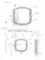
- Fig. 1 is a sectional view schematically showing the configuration of a vitreous silica crucible.
- a vitreous silica crucible 12 of the present embodiment includes an inner transparent vitreous silica layer 11 and an outer bubble-containing vitreous silica layer 14.
- the vitreous silica crucible 12 is placed on a susceptor (not shown) in such a manner that an opening thereof is oriented upward.
- the vitreous silica crucible 12 includes a round portion (may be referred to as "corner") 17 having a relatively large curvature, a cylindrical sidewall 15 having an upward-opening rim, and a mortar-shaped bottom 16 including a straight line or a curve having a relatively small curvature.
- the round portion 17 connects the sidewall 15 and the bottom 16 and refers to a portion between the point at which a tangential line to the curve of the round portion 17 overlaps the sidewall 15 of the vitreous silica crucible 12 and the point at which the round portion 17 has a common tangential line with the bottom 16.
- the sidewall 15 of the crucible is a cylindrical portion in parallel with the central axis (z-axis) of the crucible and extends approximately directly downward from the opening of the crucible.
- the sidewall 15 need not necessarily be completely in parallel with the z-axis and may be inclined in such a manner to gradually widen toward the opening.
- the sidewall 15 may also be linear or gradually curved.
- the bottom 16 of the crucible is an approximately discoid portion including a point of intersection with the z-axis of the crucible.
- the round portion 17 is formed between the bottom 16 and the sidewall 15.
- the shape of the crucible bottom 16 may be round or flat
- the curvature or angle of the round portion 17 may be freely set. If the crucible bottom 16 is round, the bottom 16 has a moderate curvature. Accordingly, the curvature difference between the bottom 16 and the round portion 17 is very small compared to that when the bottom is flat.
- the point at which the sidewall 15 of the vitreous silica crucible 12 starts to curve may be defined as the boundary between the sidewall 15 and the round portion 17.
- the portion where the curvature of the crucible bottom is constant may be defined as the bottom 16.
- the point at which the curvature starts to change when the distance from the center of the crucible bottom is increased may be defined as the boundary between the bottom 16 and the round portion 17.
- the bottom 16 forms a flat surface or very gradually curved surface, making the curvature of the round portion 17 very large.
- the bottom 16 may be defined as a region where the inclination angle of the tangential line to the crucible sidewall with respect to an xy-plane orthogonal to the z-axis is 5 degrees or less, 10 degrees or less, 15 degrees or less, 20 degrees or less, 25 degrees or less, or 30 degrees or less.
- the sidewall 15 When using the vitreous silica crucible 12 thus shaped to pull single crystal silicon by Czochralski method (CZ method) or the like, the sidewall 15 applies a large force to the round portion 17 on the basis of the self-weight 18 thereof. Further, another force works such that the sidewall 15 falls inward. Specifically, in the initial stage of the single crystal silicon pulling process, a silicon melt is contained in the vitreous silica crucible 12 to the extent that the silicon melt reaches an upper portion of the sidewall 15. Accordingly, the silicon melt applies a large pressure to the sidewall 15, the round portion 17, and the bottom 16, thereby suppressing buckling 19 at the round portion 17 or inward fall of the sidewall 15.
- the silicon melt when the surface of the silicon melt is lowered to around the round portion 17, the silicon melt no longer applies a pressure to the sidewall 15. Furthermore, the silicon melt applies a reduced pressure to the round portion 17 and the bottom 16.
- a carbon heater (not shown) provided on the perimeter of a mold (not shown) supporting the vitreous silica crucible 12 continues to give a large amount of heat to the sidewall 15. Thus, the sidewall 15 is heated to a high temperature. Since the sidewall 15 thus heated is no longer in contact with the silicon melt, the heat has few escape routes. Thus, the sidewall 15 is heated excessively as if an empty pan were heated, which may soften the vitreous silica to the extent that it has difficulty in supporting the self-weight 18. As a result, the buckling 19 easily occurs at the round portion 17, or the sidewall 15 easily falls inward.
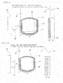
- Fig. 2 is a sectional view showing the temperature gradient of the sidewall of the vitreous silica crucible according to the first embodiment.
- Fig. 3 is a sectional view showing the temperature gradient of the round portion of the vitreous silica crucible according to the first embodiment.
- the per-unit area thermal resistance in the thickness direction of the sidewall 15 is higher than that of the round portion 17.
- the per-unit area thermal resistance in the thickness direction of the round portion 17 is higher than that of the bottom 16.
- the thermal resistance refers to a coefficient representing the degree to which, when an object is given heat, it resists the flow of the heat, as shown by the following formula, and is expressed in K/W or °C/W.
- Thermal resistance °C / W temperature difference °C ⁇ the amount of heat of heat source W
- the per-unit area thermal resistance in the thickness direction is preferably one measured under conditions similar to the conditions under which a silicon single crystal is actually pulled.
- the per-unit area thermal resistance is preferably a value measured under a condition that the ambient temperature outside the vitreous silica crucible is one of 1000°C, 1050°C, 1100°C, 1200°C, 1300°C, 1400°C, 1500°C, 1600°C; 1700°C, 1800°C, 1900°C, and 2000°C.
- the per-unit area thermal resistance is preferably a value measured under a condition that the ambient temperature inside the vitreous silica crucible is lower than the outside ambient temperature by one of 1°C, 2°C, 3°C, 4°C, 5°C, 6°C, 7°C, 8°C, 9°C, 10°C, 20°C, 30°C, 40°C, 50°C, 60°C, 70°C, 80°C, 90°C, and 100°C.
- the temperature of the surface 24 of the silicon melt contained in the vitreous silica crucible 12 needs to be maintained in a predetermined range so that single crystal silicon is successfully pulled from the melt surface 24. Since the per-unit area thermal resistance in the thickness direction of the sidewall 15 of the vitreous silica crucible 12 is high in the initial stage of the single crystal silicon pulling process, there is a large temperature deference (temperature gradient 28) between the outside and inside of the sidewall 15, as shown in Fig. 2 .
- the carbon heater 20 provided on the perimeter of the mold (not shown) supporting the vitreous silica crucible 12 needs to supply a large amount of heat 22 to the vitreous silica crucible 12.
- the sidewall 15 is heated to a high temperature and thus easily softens.
- the buckling 19 at the round portion 17 or inward fall of sidewall 15 is suppressed, since the silicon melt is applying a large pressure to the sidewall 15, the round portion 17, and the bottom 16.
- the silicon melt When the surface of the silicon melt is then lowered to around the round portion 17, the silicon melt no longer applies a pressure to the sidewall 15. Furthermore, the silicon melt applies a reduced pressure to the round portion 17 and the bottom 16. In the present embodiment, however, the per-unit area thermal resistance in the thickness direction of the round portion 17 of the vitreous silica crucible 12 is lower than that of the sidewall 15. Accordingly, the temperature difference (temperature gradient 28) between the outside and inside of the round portion 17 is reduced, as shown in Fig. 3 . For this reason, to maintain the temperature of the melt surface 24 in the predetermined range, the carbon heater 20 provided on the perimeter of the mold (not shown) supporting the vitreous silica crucible 12 only needs to supply a small amount of heat to the round portion 17.
- the round portion 17 is prevented from being heated excessively.
- the sidewall 15 is no longer in contact with the silicon melt and thus the heat has few escape routes. Accordingly, the sidewall 15 is heated as if an empty pan were heated.
- the carbon heater 20 supplies only the small amount of heat and thus the vitreous silica can be avoided from softening to the extent that it has difficulty in supporting the self-weight 18. As a result, the buckling 19 at the round portion 17 or inward fall of the sidewall 15 can be suppressed.
- the silicon melt When the surface of the silicon melt is then lowered to around the bottom 16, the silicon melt no longer applies a pressure to the sidewall 15 and the round portion 17. Furthermore, the pressure applied to the bottom 16 by the silicon melt is further reduced. In the present embodiment, however, the per-unit area thermal resistance in the thickness direction of the bottom 16 of the vitreous silica crucible 12 is lower than those of the sidewall 15 and the round portion 17. Accordingly, the temperature difference (temperature gradient) between the outside and inside of the bottom is further reduced. For this reason, to maintain the temperature of the melt surface 24 in the predetermined range, the carbon heater 20 provided on the perimeter of the mold (not shown) supporting the vitreous silica crucible 12 only needs to supply a smaller amount of heat to the bottom 16.
- the bottom 16 is prevented from being heated excessively.
- the sidewall 15 and the round portion 17 are no longer in contact with the silicon melt and thus the heat has few escape routes. Accordingly, the sidewall 15 and the round portion 17 are heated as if an empty pan were heated.
- the carbon heater 20 supplies only the smaller amount of heat, which can avoid the vitreous silica from softening to the extent that it has difficulty in supporting the self-weight 18. As a result, the buckling 19 at the round portion 17 or inward fall of the sidewall 15 can be suppressed.
- the structure of the vitreous silica crucible 12 satisfying these conditions is not limited to a particular one, since various structures are conceivable.
- Examples of the structure includes a structure where, as shown in Figs. 2 and 3 , the vitreous silica crucible 12 has two or more layers including the bubble-containing vitreous silica layer 14 and the transparent vitreous silica layer 11; the bubble-containing vitreous silica layer 14 of the sidewall 15 is larger in thickness than the bubble-containing vitreous silica layer 14 of the round portion 17; and the bubble-containing vitreous silica layer 14 of the round portion 17 is larger in thickness than the bubble-containing vitreous silica layer 14 of the bottom 16.
- the bubble-containing vitreous silica layer 14 Since the bubble-containing vitreous silica layer 14 has a high per-unit area thermal resistance, there is a large temperature difference (temperature gradient 32) between the outside and inside of the bubble-containing vitreous silica layer 14. Since the transparent vitreous silica layer 11, on the other hand, has a lower per-unit area thermal resistance than the bubble-containing vitreous silica layer 14, there is a smaller temperature difference (temperature gradient 30) between the outside and inside of the transparent vitreous silica layer 11. For this reason, if the bubble-containing vitreous silica layer 14 of the sidewall 15 has a large thickness, there is a large temperature difference (temperature gradient 28) between the outside and inside of the entire sidewall 15, as shown in Fig. 2 .
- the temperature difference (temperature gradient 28) between the outside and inside of the entire round portion 17 is smaller than that of the sidewall 15, as shown in Fig. 3 .
- the bubble-containing vitreous silica layer 14 of the bottom 16 is smaller in thickness than that of the round portion 17, the temperature difference (temperature gradient) between the outside and inside of the entire bottom 16 is smaller than that of the round portion 17.
- the vitreous silica crucible 12 satisfying the above conditions can be obtained as long as the bubble-containing vitreous silica layer 14 of the sidewall 15 is larger in thickness than the bubble-containing vitreous silica layer 14 of the round portion 17 and as long as the bubble-containing vitreous silica layer 14 of the round portion 17 is larger in thickness than the bubble-containing vitreous silica layer 14 of the bottom 16.
- Fig. 4 is a sectional view showing the temperature gradient of the sidewall of a vitreous silica crucible according to a second embodiment.
- Fig. 5 is a sectional view showing the temperature gradient of the round portion of the vitreous silica crucible according to the second embodiment.
- the vitreous silica crucible 12 has two or more layers including dissimilar materials having different thermal conductivities.
- an outer layer 44 contains aluminum as an impurity and therefore has a high per-unit area thermal resistance.
- the outer layer 44 containing aluminum as an impurity is obtained by arc-fusing a natural silica powder-alumina powder mixed material in a mold when manufacturing the vitreous silica crucible 12.
- an inner layer 46 contains nitrogen as an impurity and therefore has a low per-unit area thermal resistance.
- the inner layer 46 containing nitrogen as an impurity is obtained by arc-fusing synthetic silica powder in a nitrogen gas or ammonia gas atmosphere.
- the vitreous silica crucible 12 has two or more layers including dissimilar materials having different thermal conductivities; the outer layer 44 of the sidewall 15 is larger in thickness than the outer layer 44 of the round portion 17; and the outer layer 44 of the round portion 17 is larger in thickness than the outer layer 44 of the bottom 16. Since the outer layer 44 has a high per-unit area thermal resistance, there is a large temperature difference (temperature gradient 32) between the outside and inside of the outer layer 44. Since the inner layer 46, on the other hand, has a lower per-unit area thermal resistance than the outer layer 44, there is a small temperature difference (temperature gradient 30) between the outside and inside of the inner layer 46. For this reason, if the outer layer 44 of the sidewall 15 has a large thickness, there is a large temperature difference (temperature gradient 28) between the outside and inside of the entire sidewall 15, as shown in Fig. 4 .
- the vitreous silica crucible 12 satisfying the above conditions can be obtained as long as the outer layer 44 of the sidewall 15 is larger in thickness than that of the round portion 17 and as long as the outer layer 44 of the round portion 17 is larger in thickness than that of the bottom 16.
Landscapes
- Chemical & Material Sciences (AREA)
- Engineering & Computer Science (AREA)
- Materials Engineering (AREA)
- Organic Chemistry (AREA)
- Crystallography & Structural Chemistry (AREA)
- Metallurgy (AREA)
- Manufacturing & Machinery (AREA)
- Crystals, And After-Treatments Of Crystals (AREA)
- Glass Melting And Manufacturing (AREA)
Abstract
Description
- The present invention relates to a vitreous silica crucible.
- In recent years, there have been actively developed vitreous silica crucibles which are used to pull a silicon single crystal and can, with a simple structure, prevent the upper end of a sidewall from falling inward. As an example of such a technology, Patent Document 1 discloses a vitreous silica crucible which is used to pull a silicon single crystal and which has a circular groove on the perimeter of a sidewall and above the initial melt line. This groove is provided in a position below the upper end of a carbon susceptor.
- There have been also actively developed methods for, when manufacturing a single crystal by the Czochralski method, efficiently and reliably designing pull-up conditions under which solidification is less likely to occur in positions other than the growth interface of the growing single crystal which is being pulled up. As an example of such a technology, Patent Document 2 discloses a method for designing single crystal pulling conditions when growing a single crystal from a raw material melt-containing crucible by the Czochralski method. In this method for designing single crystal pulling conditions, an in-melt average temperature gradient G (K/cm) is obtained by dividing an in-melt temperature difference ΔT (K) between the outer peripheral surface of a single crystal to be grown and the inner wall of the crucible obtained by overall heat transfer analysis by the horizontal distance L (cm) on the melt surface between the outer peripheral surface of the single crystal to be grown and the inner wall of the crucible; and then pulling conditions are set based on the relationship between the in-melt average temperature gradient G and the incidence of solidification which occurs in positions other than the growth interface of the growing single crystal which is being pulled up.
-
- [Patent Document 1] Japanese Unexamined Patent Application Publication No.
2008-273788 - [Patent Document 2] Japanese Unexamined Patent Application Publication No.
2004-67452 - However, the traditional technologies disclosed in the above documents have room for improvement in the following respects.
- First, for the vitreous silica crucible disclosed in Patent Document 1, if the user himself or herself provide a susceptor for holding the vitreous silica crucible or if the user himself or herself determines the amount of polycrystalline silicon to be charged into the vitreous silica crucible, it may not be possible to previously form a circular groove in a position above the initial melt line and below the upper end of the carbon susceptor.
- Second, for the method disclosed in Patent Document 2, even when pulling conditions are set based on the relationship between the in-melt average temperature gradient G and the incidence of solidification which occurs in positions other than the growth interface of the growing single crystal which is being pulled up, it is difficult to effectively suppress buckling of the crucible or fall of the sidewall into the crucible.
- On the other hand, semiconductor chip manufacturing processes where 300 mm-diameter wafers are used have gone mainstream in recent years. Processes where 450 mm-diameter wafers are used are also being developed. To manufacture such wafers, a vitreous silica crucible for use in the CZ method, which is used to manufacture a single crystal silicon ingot, has of course been required to have a large opening diameter of 28 inches (71 cm), 32 inches (81 cm), 36 inches (about 91 cm), or 40 inches (102 cm). The weight of a 102 cm-diameter crucible is as heavy as about 120 kg, and the mass of a silicon melt contained therein is 900 kg or more.
- The softening point of vitreous silica is about 1200 to 1300°C. In the CZ method, on the other hand, a silicon single crystal is pulled with a silicon melt maintained at a high temperature of 1450 to 1500°C over as long as two or more weeks. That is, while the silicon single crystal is pulled, the crucible contains 900 kg or more of the silicon melt having a temperature of about 1500°C. In this case, a heater provided outside the vitreous silica crucible must heat the vitreous silica crucible in order to raise the temperature of the silicon melt to about 1500°C. The heated vitreous silica crucible softens and thus disadvantageously easily buckles or falls.
- The pulled silicon single crystal is required to have a purity of 99.999999999% or more. Accordingly, the vitreous silica crucible for pulling silicon single crystal is required not to mix a silica fragment or the like into the silicon single crystal. If the heated vitreous silica crucible softens and thus buckles or falls, a silica fragment may fall, causing a significant problem.
- The present invention has been made in view of the foregoing, and an object thereof is to provide a technology which effectively suppresses buckling of a vitreous silica crucible or fall of a sidewall into the crucible.
- The present invention provides a vitreous silica crucible for pulling single crystal silicon. The vitreous silica crucible includes a cylindrical sidewall having an upward-opening rim, a mortar-shaped bottom including a curve, and a round portion connecting the sidewall and the bottom. A per-unit area thermal resistance in a thickness direction of the sidewall is higher than a per-unit area thermal resistance in a thickness direction of the round portion.
- According to this configuration, the per-unit area thermal resistance in the thickness direction of the sidewall is higher than the per-unit area thermal resistance in the thickness direction of the round portion. Thus, while the single crystal silicon is pulled, the degree to which the vitreous silica crucible is heated can be reduced at the point in time when the surface of the silicon melt comes close to the round portion. That is, excessive heating of the sidewall or round portion of the vitreous silica crucible can be suppressed at the point in time when the surface of the silicon melt comes close to the round portion. As a result, buckling of the vitreous silica crucible or fall of the sidewall into the crucible can be suppressed.
- According to the present invention, buckling of the vitreous silica crucible or fall of the sidewall into the crucible can be suppressed.
-
-
Fig. 1 is a sectional view showing the configuration of a vitreous silica crucible of a first embodiment. -
Fig. 2 is a sectional view showing the temperature gradient of the sidewall of the vitreous silica crucible according to the first embodiment. -
Fig. 3 is a sectional view showing the temperature gradient of the round portion of the vitreous silica crucible according to the first embodiment. -
Fig. 4 is a sectional view showing the temperature gradient of the sidewall of a vitreous silica crucible according to a second embodiment. -
Fig. 5 is a sectional view showing the temperature gradient of the round portion of the vitreous silica crucible according to the second embodiment. - Hereafter, embodiments of the present invention will be described by use of the drawings. Like components are given like reference signs throughout the drawings and therefore description thereof will be omitted as appropriate.
-
Fig. 1 is a sectional view schematically showing the configuration of a vitreous silica crucible. Avitreous silica crucible 12 of the present embodiment includes an inner transparentvitreous silica layer 11 and an outer bubble-containingvitreous silica layer 14. When using thevitreous silica crucible 12 to pull single crystal silicon by the Czochralski method (CZ method) or the like, thevitreous silica crucible 12 is placed on a susceptor (not shown) in such a manner that an opening thereof is oriented upward. - The vitreous silica crucible 12 includes a round portion (may be referred to as "corner") 17 having a relatively large curvature, a
cylindrical sidewall 15 having an upward-opening rim, and a mortar-shaped bottom 16 including a straight line or a curve having a relatively small curvature. In the present embodiment, theround portion 17 connects thesidewall 15 and thebottom 16 and refers to a portion between the point at which a tangential line to the curve of theround portion 17 overlaps thesidewall 15 of thevitreous silica crucible 12 and the point at which theround portion 17 has a common tangential line with thebottom 16. - More specifically, the
sidewall 15 of the crucible is a cylindrical portion in parallel with the central axis (z-axis) of the crucible and extends approximately directly downward from the opening of the crucible. Note that thesidewall 15 need not necessarily be completely in parallel with the z-axis and may be inclined in such a manner to gradually widen toward the opening. Thesidewall 15 may also be linear or gradually curved. - The
bottom 16 of the crucible is an approximately discoid portion including a point of intersection with the z-axis of the crucible. Theround portion 17 is formed between thebottom 16 and thesidewall 15. The shape of thecrucible bottom 16 may be round or flat The curvature or angle of theround portion 17 may be freely set. If thecrucible bottom 16 is round, thebottom 16 has a moderate curvature. Accordingly, the curvature difference between thebottom 16 and theround portion 17 is very small compared to that when the bottom is flat. For example, the point at which thesidewall 15 of thevitreous silica crucible 12 starts to curve may be defined as the boundary between thesidewall 15 and theround portion 17. The portion where the curvature of the crucible bottom is constant may be defined as thebottom 16. The point at which the curvature starts to change when the distance from the center of the crucible bottom is increased may be defined as the boundary between thebottom 16 and theround portion 17. - If the
crucible bottom 16 is flat, thebottom 16 forms a flat surface or very gradually curved surface, making the curvature of theround portion 17 very large. Note that thebottom 16 may be defined as a region where the inclination angle of the tangential line to the crucible sidewall with respect to an xy-plane orthogonal to the z-axis is 5 degrees or less, 10 degrees or less, 15 degrees or less, 20 degrees or less, 25 degrees or less, or 30 degrees or less. - When using the
vitreous silica crucible 12 thus shaped to pull single crystal silicon by Czochralski method (CZ method) or the like, thesidewall 15 applies a large force to theround portion 17 on the basis of the self-weight 18 thereof. Further, another force works such that thesidewall 15 falls inward. Specifically, in the initial stage of the single crystal silicon pulling process, a silicon melt is contained in thevitreous silica crucible 12 to the extent that the silicon melt reaches an upper portion of thesidewall 15. Accordingly, the silicon melt applies a large pressure to thesidewall 15, theround portion 17, and the bottom 16, thereby suppressing buckling 19 at theround portion 17 or inward fall of thesidewall 15. - However, when the surface of the silicon melt is lowered to around the
round portion 17, the silicon melt no longer applies a pressure to thesidewall 15. Furthermore, the silicon melt applies a reduced pressure to theround portion 17 and the bottom 16. On the other hand, a carbon heater (not shown) provided on the perimeter of a mold (not shown) supporting thevitreous silica crucible 12 continues to give a large amount of heat to thesidewall 15. Thus, thesidewall 15 is heated to a high temperature. Since thesidewall 15 thus heated is no longer in contact with the silicon melt, the heat has few escape routes. Thus, thesidewall 15 is heated excessively as if an empty pan were heated, which may soften the vitreous silica to the extent that it has difficulty in supporting the self-weight 18. As a result, the buckling 19 easily occurs at theround portion 17, or thesidewall 15 easily falls inward. -
Fig. 2 is a sectional view showing the temperature gradient of the sidewall of the vitreous silica crucible according to the first embodiment.Fig. 3 is a sectional view showing the temperature gradient of the round portion of the vitreous silica crucible according to the first embodiment. - In the present embodiment, the per-unit area thermal resistance in the thickness direction of the
sidewall 15 is higher than that of theround portion 17. The per-unit area thermal resistance in the thickness direction of theround portion 17 is higher than that of the bottom 16. As used herein, the thermal resistance refers to a coefficient representing the degree to which, when an object is given heat, it resists the flow of the heat, as shown by the following formula, and is expressed in K/W or °C/W.
- Note that in the present embodiment, the per-unit area thermal resistance in the thickness direction is preferably one measured under conditions similar to the conditions under which a silicon single crystal is actually pulled. Specifically, the per-unit area thermal resistance is preferably a value measured under a condition that the ambient temperature outside the vitreous silica crucible is one of 1000°C, 1050°C, 1100°C, 1200°C, 1300°C, 1400°C, 1500°C, 1600°C; 1700°C, 1800°C, 1900°C, and 2000°C. Furthermore, the per-unit area thermal resistance is preferably a value measured under a condition that the ambient temperature inside the vitreous silica crucible is lower than the outside ambient temperature by one of 1°C, 2°C, 3°C, 4°C, 5°C, 6°C, 7°C, 8°C, 9°C, 10°C, 20°C, 30°C, 40°C, 50°C, 60°C, 70°C, 80°C, 90°C, and 100°C.
- In the present embodiment, the temperature of the
surface 24 of the silicon melt contained in thevitreous silica crucible 12 needs to be maintained in a predetermined range so that single crystal silicon is successfully pulled from themelt surface 24. Since the per-unit area thermal resistance in the thickness direction of thesidewall 15 of thevitreous silica crucible 12 is high in the initial stage of the single crystal silicon pulling process, there is a large temperature deference (temperature gradient 28) between the outside and inside of thesidewall 15, as shown inFig. 2 . For this reason, to maintain the temperature of themelt surface 24 in the predetermined range, thecarbon heater 20 provided on the perimeter of the mold (not shown) supporting thevitreous silica crucible 12 needs to supply a large amount ofheat 22 to thevitreous silica crucible 12. By doing so, thesidewall 15 is heated to a high temperature and thus easily softens. However, the buckling 19 at theround portion 17 or inward fall ofsidewall 15 is suppressed, since the silicon melt is applying a large pressure to thesidewall 15, theround portion 17, and the bottom 16. - When the surface of the silicon melt is then lowered to around the
round portion 17, the silicon melt no longer applies a pressure to thesidewall 15. Furthermore, the silicon melt applies a reduced pressure to theround portion 17 and the bottom 16. In the present embodiment, however, the per-unit area thermal resistance in the thickness direction of theround portion 17 of thevitreous silica crucible 12 is lower than that of thesidewall 15. Accordingly, the temperature difference (temperature gradient 28) between the outside and inside of theround portion 17 is reduced, as shown inFig. 3 . For this reason, to maintain the temperature of themelt surface 24 in the predetermined range, thecarbon heater 20 provided on the perimeter of the mold (not shown) supporting thevitreous silica crucible 12 only needs to supply a small amount of heat to theround portion 17. As a result, theround portion 17 is prevented from being heated excessively. On the other hand, thesidewall 15 is no longer in contact with the silicon melt and thus the heat has few escape routes. Accordingly, thesidewall 15 is heated as if an empty pan were heated. However, thecarbon heater 20 supplies only the small amount of heat and thus the vitreous silica can be avoided from softening to the extent that it has difficulty in supporting the self-weight 18. As a result, the buckling 19 at theround portion 17 or inward fall of thesidewall 15 can be suppressed. - When the surface of the silicon melt is then lowered to around the bottom 16, the silicon melt no longer applies a pressure to the
sidewall 15 and theround portion 17. Furthermore, the pressure applied to the bottom 16 by the silicon melt is further reduced. In the present embodiment, however, the per-unit area thermal resistance in the thickness direction of the bottom 16 of thevitreous silica crucible 12 is lower than those of thesidewall 15 and theround portion 17. Accordingly, the temperature difference (temperature gradient) between the outside and inside of the bottom is further reduced. For this reason, to maintain the temperature of themelt surface 24 in the predetermined range, thecarbon heater 20 provided on the perimeter of the mold (not shown) supporting thevitreous silica crucible 12 only needs to supply a smaller amount of heat to the bottom 16. Thus, the bottom 16 is prevented from being heated excessively. On the other hand, thesidewall 15 and theround portion 17 are no longer in contact with the silicon melt and thus the heat has few escape routes. Accordingly, thesidewall 15 and theround portion 17 are heated as if an empty pan were heated. However, thecarbon heater 20 supplies only the smaller amount of heat, which can avoid the vitreous silica from softening to the extent that it has difficulty in supporting the self-weight 18. As a result, the buckling 19 at theround portion 17 or inward fall of thesidewall 15 can be suppressed. - The structure of the
vitreous silica crucible 12 satisfying these conditions is not limited to a particular one, since various structures are conceivable. Examples of the structure includes a structure where, as shown inFigs. 2 and3 , thevitreous silica crucible 12 has two or more layers including the bubble-containingvitreous silica layer 14 and the transparentvitreous silica layer 11; the bubble-containingvitreous silica layer 14 of thesidewall 15 is larger in thickness than the bubble-containingvitreous silica layer 14 of theround portion 17; and the bubble-containingvitreous silica layer 14 of theround portion 17 is larger in thickness than the bubble-containingvitreous silica layer 14 of the bottom 16. Since the bubble-containingvitreous silica layer 14 has a high per-unit area thermal resistance, there is a large temperature difference (temperature gradient 32) between the outside and inside of the bubble-containingvitreous silica layer 14. Since the transparentvitreous silica layer 11, on the other hand, has a lower per-unit area thermal resistance than the bubble-containingvitreous silica layer 14, there is a smaller temperature difference (temperature gradient 30) between the outside and inside of the transparentvitreous silica layer 11. For this reason, if the bubble-containingvitreous silica layer 14 of thesidewall 15 has a large thickness, there is a large temperature difference (temperature gradient 28) between the outside and inside of theentire sidewall 15, as shown inFig. 2 . - On the other hand, if the bubble-containing
vitreous silica layer 14 of theround portion 17 is smaller in thickness than that of thesidewall 15, the temperature difference (temperature gradient 28) between the outside and inside of theentire round portion 17 is smaller than that of thesidewall 15, as shown inFig. 3 . Furthermore, if the bubble-containingvitreous silica layer 14 of the bottom 16 is smaller in thickness than that of theround portion 17, the temperature difference (temperature gradient) between the outside and inside of the entire bottom 16 is smaller than that of theround portion 17. Accordingly, thevitreous silica crucible 12 satisfying the above conditions can be obtained as long as the bubble-containingvitreous silica layer 14 of thesidewall 15 is larger in thickness than the bubble-containingvitreous silica layer 14 of theround portion 17 and as long as the bubble-containingvitreous silica layer 14 of theround portion 17 is larger in thickness than the bubble-containingvitreous silica layer 14 of the bottom 16. -
Fig. 4 is a sectional view showing the temperature gradient of the sidewall of a vitreous silica crucible according to a second embodiment.Fig. 5 is a sectional view showing the temperature gradient of the round portion of the vitreous silica crucible according to the second embodiment. - In the present embodiment, as shown in
Figs. 4 and5 , thevitreous silica crucible 12 has two or more layers including dissimilar materials having different thermal conductivities. Specifically, of the two or more layers, anouter layer 44 contains aluminum as an impurity and therefore has a high per-unit area thermal resistance. Theouter layer 44 containing aluminum as an impurity is obtained by arc-fusing a natural silica powder-alumina powder mixed material in a mold when manufacturing thevitreous silica crucible 12. Of the two or more layers, aninner layer 46 contains nitrogen as an impurity and therefore has a low per-unit area thermal resistance. Theinner layer 46 containing nitrogen as an impurity is obtained by arc-fusing synthetic silica powder in a nitrogen gas or ammonia gas atmosphere. - In the example shown in
Figs. 4 and5 , thevitreous silica crucible 12 has two or more layers including dissimilar materials having different thermal conductivities; theouter layer 44 of thesidewall 15 is larger in thickness than theouter layer 44 of theround portion 17; and theouter layer 44 of theround portion 17 is larger in thickness than theouter layer 44 of the bottom 16. Since theouter layer 44 has a high per-unit area thermal resistance, there is a large temperature difference (temperature gradient 32) between the outside and inside of theouter layer 44. Since theinner layer 46, on the other hand, has a lower per-unit area thermal resistance than theouter layer 44, there is a small temperature difference (temperature gradient 30) between the outside and inside of theinner layer 46. For this reason, if theouter layer 44 of thesidewall 15 has a large thickness, there is a large temperature difference (temperature gradient 28) between the outside and inside of theentire sidewall 15, as shown inFig. 4 . - On the other hand, if the
outer layer 44 of theround portion 17 is smaller in thickness than that of thesidewall 15, the temperature difference (temperature gradient 28) between the outside and inside of theentire round portion 17 is smaller than that of thesidewall 15, as shown inFig. 5 . Furthermore, if theouter layer 44 of the bottom 16 is smaller in thickness than that of theround portion 17, the temperature difference (temperature gradient) between the outside and inside of the entire bottom 16 is smaller than that of theround portion 17. Accordingly, thevitreous silica crucible 12 satisfying the above conditions can be obtained as long as theouter layer 44 of thesidewall 15 is larger in thickness than that of theround portion 17 and as long as theouter layer 44 of theround portion 17 is larger in thickness than that of the bottom 16. - While the embodiments of the present invention have been described with reference to the drawings, the embodiments are illustrative only. Various configurations other than those described above can be employed.
-
- 11
- transparent vitreous silica layer
- 12
- vitreous silica crucible
- 14
- bubble-containing vitreous silica layer
- 15
- sidewall
- 16
- bottom
- 17
- round portion
- 18
- self-weight
- 19
- buckling
- 20
- carbon heater
- 22
- the amount of heat
- 24
- liquid surface
- 28
- temperature gradient
- 30
- temperature gradient
- 32
- temperature gradient
- 44
- outer layer
- 46
- inner layer
Claims (7)
- A vitreous silica crucible for pulling single crystal silicon, comprising:a cylindrical sidewall having an upward-opening rim;a mortar-shaped bottom including a curve; anda round portion connecting the sidewall and the bottom, whereina per-unit area thermal resistance in a thickness direction of the sidewall is higher than a per-unit area thermal resistance in a thickness direction of the round portion.
- The vitreous silica crucible of claim 1, wherein the per-unit area thermal resistance in the thickness direction of the round portion is higher than a per-unit area thermal resistance in a thickness direction of the bottom.
- The vitreous silica crucible of claim 1, wherein
the vitreous silica crucible has two or more layers including a bubble-containing vitreous silica layer and a transparent vitreous silica layer, and
the bubble-containing vitreous silica layer of the sidewall is larger in thickness than the bubble-containing vitreous silica layer of the round portion. - The vitreous silica crucible of claim 3, wherein the bubble-containing vitreous silica layer of the round portion is larger in thickness than the bubble-containing vitreous silica layer of the bottom.
- The vitreous silica crucible of claim 1, wherein the vitreous silica crucible has two or more layers comprising dissimilar materials having different thermal conductivities.
- The vitreous silica crucible of claim 5, wherein of the two or more layers, an outer layer contains aluminum as an impurity.
- The vitreous silica crucible of claim 5, wherein of the two or more layers, an inner layer contains nitrogen as an impurity.
Applications Claiming Priority (2)
| Application Number | Priority Date | Filing Date | Title |
|---|---|---|---|
| JP2011290478A JP5762945B2 (en) | 2011-12-30 | 2011-12-30 | Silica glass crucible |
| PCT/JP2012/078257 WO2013099431A1 (en) | 2011-12-30 | 2012-10-31 | Silica glass crucible |
Publications (3)
| Publication Number | Publication Date |
|---|---|
| EP2799597A1 true EP2799597A1 (en) | 2014-11-05 |
| EP2799597A4 EP2799597A4 (en) | 2015-08-19 |
| EP2799597B1 EP2799597B1 (en) | 2019-09-25 |
Family
ID=48696931
Family Applications (1)
| Application Number | Title | Priority Date | Filing Date |
|---|---|---|---|
| EP12861985.5A Active EP2799597B1 (en) | 2011-12-30 | 2012-10-31 | Silica glass crucible |
Country Status (7)
| Country | Link |
|---|---|
| US (1) | US9758900B2 (en) |
| EP (1) | EP2799597B1 (en) |
| JP (1) | JP5762945B2 (en) |
| KR (1) | KR101638586B1 (en) |
| CN (1) | CN104114754B (en) |
| TW (1) | TWI507574B (en) |
| WO (1) | WO2013099431A1 (en) |
Families Citing this family (3)
| Publication number | Priority date | Publication date | Assignee | Title |
|---|---|---|---|---|
| EP3508286B1 (en) | 2016-08-31 | 2021-12-22 | Dowa Electronics Materials Co., Ltd. | Silver-coated alloy powder, electrically conductive paste, electronic part, and electric device |
| CN109563639B (en) * | 2016-09-13 | 2021-10-26 | 胜高股份有限公司 | Quartz glass crucible and method for producing same |
| JP7761376B2 (en) * | 2020-07-30 | 2025-10-28 | 信越石英株式会社 | Quartz glass crucible |
Family Cites Families (19)
| Publication number | Priority date | Publication date | Assignee | Title |
|---|---|---|---|---|
| JP2933404B2 (en) * | 1990-06-25 | 1999-08-16 | 信越石英 株式会社 | Quartz glass crucible for pulling silicon single crystal and its manufacturing method |
| JP3136533B2 (en) * | 1995-04-28 | 2001-02-19 | 三菱マテリアルクォーツ株式会社 | Quartz crucible for pulling silicon single crystal |
| TWI221486B (en) * | 1998-07-31 | 2004-10-01 | Shinetsu Handotai Kk | Quartz glass crucible for pulling silicon single crystal and production process for such |
| JP3888065B2 (en) * | 2001-01-30 | 2007-02-28 | 株式会社Sumco | Quartz crucible |
| JP4548962B2 (en) * | 2001-03-28 | 2010-09-22 | ジャパンスーパークォーツ株式会社 | Silica glass crucible and silicon single crystal pulling method using the same |
| JP2002326889A (en) * | 2001-04-27 | 2002-11-12 | Toshiba Ceramics Co Ltd | Quartz glass crucible for pulling silicon single crystal |
| US7118789B2 (en) * | 2001-07-16 | 2006-10-10 | Heraeus Shin-Etsu America | Silica glass crucible |
| DE10217946A1 (en) | 2002-04-22 | 2003-11-13 | Heraeus Quarzglas | Quartz glass crucible and method of manufacturing the same |
| JP2004067452A (en) | 2002-08-07 | 2004-03-04 | Shin Etsu Handotai Co Ltd | Method for designing condition for pulling single crystal |
| JP4863927B2 (en) | 2007-04-27 | 2012-01-25 | 信越石英株式会社 | Silica glass crucible for pulling silicon single crystal and method for producing silicon single crystal using the same |
| EP2248776A4 (en) * | 2008-02-05 | 2013-10-30 | Japan Super Quartz Corp | Quartz glass crucible |
| DE102008033945B4 (en) * | 2008-07-19 | 2012-03-08 | Heraeus Quarzglas Gmbh & Co. Kg | Process for the preparation of quartz glass doped with nitrogen and quartz glass grains suitable for carrying out the process, process for producing a quartz glass strand and method for producing a quartz glass crucible |
| JP4975012B2 (en) * | 2008-12-29 | 2012-07-11 | ジャパンスーパークォーツ株式会社 | Silica glass crucible for pulling silicon single crystal and manufacturing method thereof |
| DE102009048741A1 (en) * | 2009-03-20 | 2010-09-30 | Access E.V. | Crucible for melting and crystallizing a metal, a semiconductor or a metal alloy, a component for a crucible base of a crucible and method for producing a component |
| JP4987029B2 (en) * | 2009-04-02 | 2012-07-25 | ジャパンスーパークォーツ株式会社 | Silica glass crucible for pulling silicon single crystals |
| US9187357B2 (en) * | 2009-07-31 | 2015-11-17 | Japan Super Quartz Corporation | Vitreous silica crucible having outer, intermediate, and inner layers |
| JP5334315B2 (en) * | 2009-09-30 | 2013-11-06 | コバレントマテリアル株式会社 | Silica glass crucible for silicon single crystal pulling |
| JP5289293B2 (en) * | 2009-12-14 | 2013-09-11 | 株式会社Sumco | Quartz crucible for single crystal pulling |
| CN102127806B (en) * | 2010-10-28 | 2012-09-05 | 杭州先进石英材料有限公司 | Quartz glass crucible and preparation method thereof |
-
2011
- 2011-12-30 JP JP2011290478A patent/JP5762945B2/en active Active
-
2012
- 2012-10-31 CN CN201280065351.XA patent/CN104114754B/en active Active
- 2012-10-31 US US14/369,151 patent/US9758900B2/en not_active Expired - Fee Related
- 2012-10-31 KR KR1020147020101A patent/KR101638586B1/en active Active
- 2012-10-31 EP EP12861985.5A patent/EP2799597B1/en active Active
- 2012-10-31 WO PCT/JP2012/078257 patent/WO2013099431A1/en not_active Ceased
- 2012-11-01 TW TW101140628A patent/TWI507574B/en active
Also Published As
| Publication number | Publication date |
|---|---|
| KR20140107513A (en) | 2014-09-04 |
| EP2799597A4 (en) | 2015-08-19 |
| KR101638586B1 (en) | 2016-07-11 |
| TW201331431A (en) | 2013-08-01 |
| WO2013099431A1 (en) | 2013-07-04 |
| EP2799597B1 (en) | 2019-09-25 |
| CN104114754A (en) | 2014-10-22 |
| JP5762945B2 (en) | 2015-08-12 |
| US20150027364A1 (en) | 2015-01-29 |
| TWI507574B (en) | 2015-11-11 |
| JP2013139359A (en) | 2013-07-18 |
| US9758900B2 (en) | 2017-09-12 |
| CN104114754B (en) | 2016-10-12 |
Similar Documents
| Publication | Publication Date | Title |
|---|---|---|
| TWI410535B (en) | Vitreous silica crucible for pulling silicon single crystal | |
| CN102272359B (en) | Single crystal manufacturing apparatus, method for manufacturing single crystal, and single crystal | |
| CN108265328A (en) | Crystal pulling system and method including crucible and conditioning member | |
| CN105358743B (en) | Single-crystal manufacturing apparatus and monocrystalline manufacture method | |
| US20100089308A1 (en) | Silica glass crucible and method for pulling single-crystal silicon | |
| US9187357B2 (en) | Vitreous silica crucible having outer, intermediate, and inner layers | |
| CN106414815A (en) | Crystal growing system and crucibles for enhancing the heat transfer to the melt by desinging a double crucible | |
| US8721787B2 (en) | Method for manufacturing silicon single crystal | |
| US8105514B2 (en) | Mold for producing silica crucible | |
| EP2799597B1 (en) | Silica glass crucible | |
| EP2589687A1 (en) | Crucible and method for the production of a (near ) monocrystalline semiconductor ingot | |
| CN102758247A (en) | Silica glass crucible and method of pulling silicon single crystal with silica glass crucible | |
| JPH0412086A (en) | Silicon single crystal production equipment | |
| JP6351534B2 (en) | Silica glass crucible for pulling silicon single crystals | |
| TWI481750B (en) | Removing a sheet from the surface of a melt using elasticity and buoyancy | |
| EP2799596B1 (en) | Silica glass crucible and method for producing monocrystalline silicon using same | |
| JP4851221B2 (en) | Quartz glass crucibles and applications | |
| JP6208080B2 (en) | Quartz glass crucible | |
| CN105780105B (en) | The preparation method of monocrystalline silicon | |
| CN101619485A (en) | Silica glass crucible and method for pulling up single crystal silicon using silica glass crucible | |
| JP2007076974A (en) | Crucible for pulling silicon single crystal | |
| WO2021131321A1 (en) | Quartz glass crucible and method for producing same |
Legal Events
| Date | Code | Title | Description |
|---|---|---|---|
| PUAI | Public reference made under article 153(3) epc to a published international application that has entered the european phase |
Free format text: ORIGINAL CODE: 0009012 |
|
| 17P | Request for examination filed |
Effective date: 20140718 |
|
| AK | Designated contracting states |
Kind code of ref document: A1 Designated state(s): AL AT BE BG CH CY CZ DE DK EE ES FI FR GB GR HR HU IE IS IT LI LT LU LV MC MK MT NL NO PL PT RO RS SE SI SK SM TR |
|
| DAX | Request for extension of the european patent (deleted) | ||
| RA4 | Supplementary search report drawn up and despatched (corrected) |
Effective date: 20150722 |
|
| RIC1 | Information provided on ipc code assigned before grant |
Ipc: C30B 29/06 20060101AFI20150716BHEP Ipc: C03B 19/09 20060101ALI20150716BHEP Ipc: C30B 15/10 20060101ALI20150716BHEP Ipc: C03B 20/00 20060101ALI20150716BHEP |
|
| STAA | Information on the status of an ep patent application or granted ep patent |
Free format text: STATUS: EXAMINATION IS IN PROGRESS |
|
| 17Q | First examination report despatched |
Effective date: 20180208 |
|
| REG | Reference to a national code |
Ref country code: DE Ref legal event code: R079 Ref document number: 602012064378 Country of ref document: DE Free format text: PREVIOUS MAIN CLASS: C30B0029060000 Ipc: C30B0035000000 |
|
| RIC1 | Information provided on ipc code assigned before grant |
Ipc: C30B 35/00 20060101AFI20190426BHEP Ipc: C03B 19/09 20060101ALI20190426BHEP Ipc: C30B 15/10 20060101ALI20190426BHEP Ipc: C30B 29/06 20060101ALN20190426BHEP |
|
| GRAP | Despatch of communication of intention to grant a patent |
Free format text: ORIGINAL CODE: EPIDOSNIGR1 |
|
| STAA | Information on the status of an ep patent application or granted ep patent |
Free format text: STATUS: GRANT OF PATENT IS INTENDED |
|
| RIC1 | Information provided on ipc code assigned before grant |
Ipc: C30B 15/10 20060101ALI20190506BHEP Ipc: C03B 19/09 20060101ALI20190506BHEP Ipc: C30B 35/00 20060101AFI20190506BHEP Ipc: C30B 29/06 20060101ALN20190506BHEP |
|
| INTG | Intention to grant announced |
Effective date: 20190607 |
|
| RIN1 | Information on inventor provided before grant (corrected) |
Inventor name: YOSHIOKA, TAKUMA Inventor name: SATO, TADAHIRO Inventor name: SUDO, TOSHIAKI Inventor name: KITAHARA, KEN Inventor name: KISHI, HIROSHI |
|
| GRAS | Grant fee paid |
Free format text: ORIGINAL CODE: EPIDOSNIGR3 |
|
| GRAA | (expected) grant |
Free format text: ORIGINAL CODE: 0009210 |
|
| STAA | Information on the status of an ep patent application or granted ep patent |
Free format text: STATUS: THE PATENT HAS BEEN GRANTED |
|
| AK | Designated contracting states |
Kind code of ref document: B1 Designated state(s): AL AT BE BG CH CY CZ DE DK EE ES FI FR GB GR HR HU IE IS IT LI LT LU LV MC MK MT NL NO PL PT RO RS SE SI SK SM TR |
|
| REG | Reference to a national code |
Ref country code: GB Ref legal event code: FG4D |
|
| REG | Reference to a national code |
Ref country code: CH Ref legal event code: EP |
|
| REG | Reference to a national code |
Ref country code: DE Ref legal event code: R096 Ref document number: 602012064378 Country of ref document: DE |
|
| REG | Reference to a national code |
Ref country code: AT Ref legal event code: REF Ref document number: 1183917 Country of ref document: AT Kind code of ref document: T Effective date: 20191015 |
|
| REG | Reference to a national code |
Ref country code: IE Ref legal event code: FG4D |
|
| REG | Reference to a national code |
Ref country code: NL Ref legal event code: MP Effective date: 20190925 |
|
| PG25 | Lapsed in a contracting state [announced via postgrant information from national office to epo] |
Ref country code: NO Free format text: LAPSE BECAUSE OF FAILURE TO SUBMIT A TRANSLATION OF THE DESCRIPTION OR TO PAY THE FEE WITHIN THE PRESCRIBED TIME-LIMIT Effective date: 20191225 Ref country code: BG Free format text: LAPSE BECAUSE OF FAILURE TO SUBMIT A TRANSLATION OF THE DESCRIPTION OR TO PAY THE FEE WITHIN THE PRESCRIBED TIME-LIMIT Effective date: 20191225 Ref country code: LT Free format text: LAPSE BECAUSE OF FAILURE TO SUBMIT A TRANSLATION OF THE DESCRIPTION OR TO PAY THE FEE WITHIN THE PRESCRIBED TIME-LIMIT Effective date: 20190925 Ref country code: HR Free format text: LAPSE BECAUSE OF FAILURE TO SUBMIT A TRANSLATION OF THE DESCRIPTION OR TO PAY THE FEE WITHIN THE PRESCRIBED TIME-LIMIT Effective date: 20190925 Ref country code: SE Free format text: LAPSE BECAUSE OF FAILURE TO SUBMIT A TRANSLATION OF THE DESCRIPTION OR TO PAY THE FEE WITHIN THE PRESCRIBED TIME-LIMIT Effective date: 20190925 Ref country code: FI Free format text: LAPSE BECAUSE OF FAILURE TO SUBMIT A TRANSLATION OF THE DESCRIPTION OR TO PAY THE FEE WITHIN THE PRESCRIBED TIME-LIMIT Effective date: 20190925 |
|
| REG | Reference to a national code |
Ref country code: LT Ref legal event code: MG4D |
|
| PG25 | Lapsed in a contracting state [announced via postgrant information from national office to epo] |
Ref country code: GR Free format text: LAPSE BECAUSE OF FAILURE TO SUBMIT A TRANSLATION OF THE DESCRIPTION OR TO PAY THE FEE WITHIN THE PRESCRIBED TIME-LIMIT Effective date: 20191226 Ref country code: RS Free format text: LAPSE BECAUSE OF FAILURE TO SUBMIT A TRANSLATION OF THE DESCRIPTION OR TO PAY THE FEE WITHIN THE PRESCRIBED TIME-LIMIT Effective date: 20190925 Ref country code: LV Free format text: LAPSE BECAUSE OF FAILURE TO SUBMIT A TRANSLATION OF THE DESCRIPTION OR TO PAY THE FEE WITHIN THE PRESCRIBED TIME-LIMIT Effective date: 20190925 |
|
| REG | Reference to a national code |
Ref country code: AT Ref legal event code: MK05 Ref document number: 1183917 Country of ref document: AT Kind code of ref document: T Effective date: 20190925 |
|
| PG25 | Lapsed in a contracting state [announced via postgrant information from national office to epo] |
Ref country code: PT Free format text: LAPSE BECAUSE OF FAILURE TO SUBMIT A TRANSLATION OF THE DESCRIPTION OR TO PAY THE FEE WITHIN THE PRESCRIBED TIME-LIMIT Effective date: 20200127 Ref country code: AL Free format text: LAPSE BECAUSE OF FAILURE TO SUBMIT A TRANSLATION OF THE DESCRIPTION OR TO PAY THE FEE WITHIN THE PRESCRIBED TIME-LIMIT Effective date: 20190925 Ref country code: RO Free format text: LAPSE BECAUSE OF FAILURE TO SUBMIT A TRANSLATION OF THE DESCRIPTION OR TO PAY THE FEE WITHIN THE PRESCRIBED TIME-LIMIT Effective date: 20190925 Ref country code: AT Free format text: LAPSE BECAUSE OF FAILURE TO SUBMIT A TRANSLATION OF THE DESCRIPTION OR TO PAY THE FEE WITHIN THE PRESCRIBED TIME-LIMIT Effective date: 20190925 Ref country code: EE Free format text: LAPSE BECAUSE OF FAILURE TO SUBMIT A TRANSLATION OF THE DESCRIPTION OR TO PAY THE FEE WITHIN THE PRESCRIBED TIME-LIMIT Effective date: 20190925 Ref country code: IT Free format text: LAPSE BECAUSE OF FAILURE TO SUBMIT A TRANSLATION OF THE DESCRIPTION OR TO PAY THE FEE WITHIN THE PRESCRIBED TIME-LIMIT Effective date: 20190925 Ref country code: PL Free format text: LAPSE BECAUSE OF FAILURE TO SUBMIT A TRANSLATION OF THE DESCRIPTION OR TO PAY THE FEE WITHIN THE PRESCRIBED TIME-LIMIT Effective date: 20190925 Ref country code: NL Free format text: LAPSE BECAUSE OF FAILURE TO SUBMIT A TRANSLATION OF THE DESCRIPTION OR TO PAY THE FEE WITHIN THE PRESCRIBED TIME-LIMIT Effective date: 20190925 Ref country code: ES Free format text: LAPSE BECAUSE OF FAILURE TO SUBMIT A TRANSLATION OF THE DESCRIPTION OR TO PAY THE FEE WITHIN THE PRESCRIBED TIME-LIMIT Effective date: 20190925 |
|
| PG25 | Lapsed in a contracting state [announced via postgrant information from national office to epo] |
Ref country code: SK Free format text: LAPSE BECAUSE OF FAILURE TO SUBMIT A TRANSLATION OF THE DESCRIPTION OR TO PAY THE FEE WITHIN THE PRESCRIBED TIME-LIMIT Effective date: 20190925 Ref country code: IS Free format text: LAPSE BECAUSE OF FAILURE TO SUBMIT A TRANSLATION OF THE DESCRIPTION OR TO PAY THE FEE WITHIN THE PRESCRIBED TIME-LIMIT Effective date: 20200224 Ref country code: SM Free format text: LAPSE BECAUSE OF FAILURE TO SUBMIT A TRANSLATION OF THE DESCRIPTION OR TO PAY THE FEE WITHIN THE PRESCRIBED TIME-LIMIT Effective date: 20190925 Ref country code: CZ Free format text: LAPSE BECAUSE OF FAILURE TO SUBMIT A TRANSLATION OF THE DESCRIPTION OR TO PAY THE FEE WITHIN THE PRESCRIBED TIME-LIMIT Effective date: 20190925 |
|
| REG | Reference to a national code |
Ref country code: CH Ref legal event code: PL |
|
| REG | Reference to a national code |
Ref country code: DE Ref legal event code: R097 Ref document number: 602012064378 Country of ref document: DE |
|
| PG2D | Information on lapse in contracting state deleted |
Ref country code: IS |
|
| PG25 | Lapsed in a contracting state [announced via postgrant information from national office to epo] |
Ref country code: LU Free format text: LAPSE BECAUSE OF NON-PAYMENT OF DUE FEES Effective date: 20191031 Ref country code: LI Free format text: LAPSE BECAUSE OF NON-PAYMENT OF DUE FEES Effective date: 20191031 Ref country code: CH Free format text: LAPSE BECAUSE OF NON-PAYMENT OF DUE FEES Effective date: 20191031 Ref country code: DK Free format text: LAPSE BECAUSE OF FAILURE TO SUBMIT A TRANSLATION OF THE DESCRIPTION OR TO PAY THE FEE WITHIN THE PRESCRIBED TIME-LIMIT Effective date: 20190925 Ref country code: IS Free format text: LAPSE BECAUSE OF FAILURE TO SUBMIT A TRANSLATION OF THE DESCRIPTION OR TO PAY THE FEE WITHIN THE PRESCRIBED TIME-LIMIT Effective date: 20200126 |
|
| PLBE | No opposition filed within time limit |
Free format text: ORIGINAL CODE: 0009261 |
|
| STAA | Information on the status of an ep patent application or granted ep patent |
Free format text: STATUS: NO OPPOSITION FILED WITHIN TIME LIMIT |
|
| REG | Reference to a national code |
Ref country code: BE Ref legal event code: MM Effective date: 20191031 |
|
| PG25 | Lapsed in a contracting state [announced via postgrant information from national office to epo] |
Ref country code: MC Free format text: LAPSE BECAUSE OF FAILURE TO SUBMIT A TRANSLATION OF THE DESCRIPTION OR TO PAY THE FEE WITHIN THE PRESCRIBED TIME-LIMIT Effective date: 20190925 Ref country code: BE Free format text: LAPSE BECAUSE OF NON-PAYMENT OF DUE FEES Effective date: 20191031 |
|
| 26N | No opposition filed |
Effective date: 20200626 |
|
| GBPC | Gb: european patent ceased through non-payment of renewal fee |
Effective date: 20191225 |
|
| PG25 | Lapsed in a contracting state [announced via postgrant information from national office to epo] |
Ref country code: IE Free format text: LAPSE BECAUSE OF NON-PAYMENT OF DUE FEES Effective date: 20191031 Ref country code: GB Free format text: LAPSE BECAUSE OF NON-PAYMENT OF DUE FEES Effective date: 20191225 Ref country code: FR Free format text: LAPSE BECAUSE OF NON-PAYMENT OF DUE FEES Effective date: 20191125 |
|
| PG25 | Lapsed in a contracting state [announced via postgrant information from national office to epo] |
Ref country code: SI Free format text: LAPSE BECAUSE OF FAILURE TO SUBMIT A TRANSLATION OF THE DESCRIPTION OR TO PAY THE FEE WITHIN THE PRESCRIBED TIME-LIMIT Effective date: 20190925 |
|
| PG25 | Lapsed in a contracting state [announced via postgrant information from national office to epo] |
Ref country code: CY Free format text: LAPSE BECAUSE OF FAILURE TO SUBMIT A TRANSLATION OF THE DESCRIPTION OR TO PAY THE FEE WITHIN THE PRESCRIBED TIME-LIMIT Effective date: 20190925 |
|
| PG25 | Lapsed in a contracting state [announced via postgrant information from national office to epo] |
Ref country code: HU Free format text: LAPSE BECAUSE OF FAILURE TO SUBMIT A TRANSLATION OF THE DESCRIPTION OR TO PAY THE FEE WITHIN THE PRESCRIBED TIME-LIMIT; INVALID AB INITIO Effective date: 20121031 Ref country code: MT Free format text: LAPSE BECAUSE OF FAILURE TO SUBMIT A TRANSLATION OF THE DESCRIPTION OR TO PAY THE FEE WITHIN THE PRESCRIBED TIME-LIMIT Effective date: 20190925 |
|
| PG25 | Lapsed in a contracting state [announced via postgrant information from national office to epo] |
Ref country code: TR Free format text: LAPSE BECAUSE OF FAILURE TO SUBMIT A TRANSLATION OF THE DESCRIPTION OR TO PAY THE FEE WITHIN THE PRESCRIBED TIME-LIMIT Effective date: 20190925 |
|
| PG25 | Lapsed in a contracting state [announced via postgrant information from national office to epo] |
Ref country code: MK Free format text: LAPSE BECAUSE OF FAILURE TO SUBMIT A TRANSLATION OF THE DESCRIPTION OR TO PAY THE FEE WITHIN THE PRESCRIBED TIME-LIMIT Effective date: 20190925 |
|
| PGFP | Annual fee paid to national office [announced via postgrant information from national office to epo] |
Ref country code: DE Payment date: 20251021 Year of fee payment: 14 |