EP2799215A1 - Perforated vacuum membrane for fibre reinforced laminates - Google Patents
Perforated vacuum membrane for fibre reinforced laminates Download PDFInfo
- Publication number
- EP2799215A1 EP2799215A1 EP20130166234 EP13166234A EP2799215A1 EP 2799215 A1 EP2799215 A1 EP 2799215A1 EP 20130166234 EP20130166234 EP 20130166234 EP 13166234 A EP13166234 A EP 13166234A EP 2799215 A1 EP2799215 A1 EP 2799215A1
- Authority
- EP
- European Patent Office
- Prior art keywords
- membrane
- stack
- mould
- openings
- composite component
- Prior art date
- Legal status (The legal status is an assumption and is not a legal conclusion. Google has not performed a legal analysis and makes no representation as to the accuracy of the status listed.)
- Granted
Links
- 239000012528 membrane Substances 0.000 title claims abstract description 136
- 239000000835 fiber Substances 0.000 title claims abstract description 53
- 239000012530 fluid Substances 0.000 claims abstract description 51
- 239000002131 composite material Substances 0.000 claims abstract description 45
- 239000011347 resin Substances 0.000 claims description 42
- 229920005989 resin Polymers 0.000 claims description 42
- 238000000034 method Methods 0.000 claims description 18
- 239000000463 material Substances 0.000 claims description 14
- 238000004519 manufacturing process Methods 0.000 claims description 13
- 230000000593 degrading effect Effects 0.000 claims description 2
- 238000002144 chemical decomposition reaction Methods 0.000 claims 1
- 239000010410 layer Substances 0.000 description 50
- 230000035699 permeability Effects 0.000 description 7
- 238000009736 wetting Methods 0.000 description 6
- 230000004888 barrier function Effects 0.000 description 5
- 238000002791 soaking Methods 0.000 description 5
- PPBRXRYQALVLMV-UHFFFAOYSA-N Styrene Chemical compound C=CC1=CC=CC=C1 PPBRXRYQALVLMV-UHFFFAOYSA-N 0.000 description 4
- 239000011162 core material Substances 0.000 description 4
- 230000009969 flowable effect Effects 0.000 description 4
- 238000007596 consolidation process Methods 0.000 description 3
- 238000009826 distribution Methods 0.000 description 3
- 238000001721 transfer moulding Methods 0.000 description 3
- NIXOWILDQLNWCW-UHFFFAOYSA-M Acrylate Chemical compound [O-]C(=O)C=C NIXOWILDQLNWCW-UHFFFAOYSA-M 0.000 description 2
- CERQOIWHTDAKMF-UHFFFAOYSA-M Methacrylate Chemical compound CC(=C)C([O-])=O CERQOIWHTDAKMF-UHFFFAOYSA-M 0.000 description 2
- 238000010438 heat treatment Methods 0.000 description 2
- 238000002347 injection Methods 0.000 description 2
- 239000007924 injection Substances 0.000 description 2
- 238000003825 pressing Methods 0.000 description 2
- 239000002344 surface layer Substances 0.000 description 2
- OKTJSMMVPCPJKN-UHFFFAOYSA-N Carbon Chemical compound [C] OKTJSMMVPCPJKN-UHFFFAOYSA-N 0.000 description 1
- 239000004593 Epoxy Substances 0.000 description 1
- 240000007182 Ochroma pyramidale Species 0.000 description 1
- 239000004793 Polystyrene Substances 0.000 description 1
- 229910052799 carbon Inorganic materials 0.000 description 1
- 230000015556 catabolic process Effects 0.000 description 1
- 239000003795 chemical substances by application Substances 0.000 description 1
- 239000012792 core layer Substances 0.000 description 1
- 230000003247 decreasing effect Effects 0.000 description 1
- 238000006731 degradation reaction Methods 0.000 description 1
- 239000003085 diluting agent Substances 0.000 description 1
- 238000010790 dilution Methods 0.000 description 1
- 239000012895 dilution Substances 0.000 description 1
- 230000000694 effects Effects 0.000 description 1
- 239000003365 glass fiber Substances 0.000 description 1
- 230000000977 initiatory effect Effects 0.000 description 1
- 239000003562 lightweight material Substances 0.000 description 1
- 239000007788 liquid Substances 0.000 description 1
- 238000002844 melting Methods 0.000 description 1
- 230000008018 melting Effects 0.000 description 1
- 238000000465 moulding Methods 0.000 description 1
- 239000004033 plastic Substances 0.000 description 1
- 229920002223 polystyrene Polymers 0.000 description 1
- 230000002787 reinforcement Effects 0.000 description 1
- 239000002904 solvent Substances 0.000 description 1
- 239000000126 substance Substances 0.000 description 1
- 229920006305 unsaturated polyester Polymers 0.000 description 1
- 239000002759 woven fabric Substances 0.000 description 1
Images
Classifications
-
- F—MECHANICAL ENGINEERING; LIGHTING; HEATING; WEAPONS; BLASTING
- F03—MACHINES OR ENGINES FOR LIQUIDS; WIND, SPRING, OR WEIGHT MOTORS; PRODUCING MECHANICAL POWER OR A REACTIVE PROPULSIVE THRUST, NOT OTHERWISE PROVIDED FOR
- F03D—WIND MOTORS
- F03D1/00—Wind motors with rotation axis substantially parallel to the air flow entering the rotor
- F03D1/06—Rotors
- F03D1/065—Rotors characterised by their construction elements
- F03D1/0675—Rotors characterised by their construction elements of the blades
-
- B—PERFORMING OPERATIONS; TRANSPORTING
- B29—WORKING OF PLASTICS; WORKING OF SUBSTANCES IN A PLASTIC STATE IN GENERAL
- B29C—SHAPING OR JOINING OF PLASTICS; SHAPING OF MATERIAL IN A PLASTIC STATE, NOT OTHERWISE PROVIDED FOR; AFTER-TREATMENT OF THE SHAPED PRODUCTS, e.g. REPAIRING
- B29C70/00—Shaping composites, i.e. plastics material comprising reinforcements, fillers or preformed parts, e.g. inserts
- B29C70/04—Shaping composites, i.e. plastics material comprising reinforcements, fillers or preformed parts, e.g. inserts comprising reinforcements only, e.g. self-reinforcing plastics
- B29C70/28—Shaping operations therefor
- B29C70/40—Shaping or impregnating by compression not applied
- B29C70/42—Shaping or impregnating by compression not applied for producing articles of definite length, i.e. discrete articles
- B29C70/46—Shaping or impregnating by compression not applied for producing articles of definite length, i.e. discrete articles using matched moulds, e.g. for deforming sheet moulding compounds [SMC] or prepregs
- B29C70/48—Shaping or impregnating by compression not applied for producing articles of definite length, i.e. discrete articles using matched moulds, e.g. for deforming sheet moulding compounds [SMC] or prepregs and impregnating the reinforcements in the closed mould, e.g. resin transfer moulding [RTM], e.g. by vacuum
-
- B—PERFORMING OPERATIONS; TRANSPORTING
- B29—WORKING OF PLASTICS; WORKING OF SUBSTANCES IN A PLASTIC STATE IN GENERAL
- B29C—SHAPING OR JOINING OF PLASTICS; SHAPING OF MATERIAL IN A PLASTIC STATE, NOT OTHERWISE PROVIDED FOR; AFTER-TREATMENT OF THE SHAPED PRODUCTS, e.g. REPAIRING
- B29C70/00—Shaping composites, i.e. plastics material comprising reinforcements, fillers or preformed parts, e.g. inserts
- B29C70/04—Shaping composites, i.e. plastics material comprising reinforcements, fillers or preformed parts, e.g. inserts comprising reinforcements only, e.g. self-reinforcing plastics
- B29C70/06—Fibrous reinforcements only
- B29C70/08—Fibrous reinforcements only comprising combinations of different forms of fibrous reinforcements incorporated in matrix material, forming one or more layers, and with or without non-reinforced layers
- B29C70/086—Fibrous reinforcements only comprising combinations of different forms of fibrous reinforcements incorporated in matrix material, forming one or more layers, and with or without non-reinforced layers and with one or more layers of pure plastics material, e.g. foam layers
-
- B—PERFORMING OPERATIONS; TRANSPORTING
- B29—WORKING OF PLASTICS; WORKING OF SUBSTANCES IN A PLASTIC STATE IN GENERAL
- B29C—SHAPING OR JOINING OF PLASTICS; SHAPING OF MATERIAL IN A PLASTIC STATE, NOT OTHERWISE PROVIDED FOR; AFTER-TREATMENT OF THE SHAPED PRODUCTS, e.g. REPAIRING
- B29C70/00—Shaping composites, i.e. plastics material comprising reinforcements, fillers or preformed parts, e.g. inserts
- B29C70/04—Shaping composites, i.e. plastics material comprising reinforcements, fillers or preformed parts, e.g. inserts comprising reinforcements only, e.g. self-reinforcing plastics
- B29C70/28—Shaping operations therefor
- B29C70/54—Component parts, details or accessories; Auxiliary operations, e.g. feeding or storage of prepregs or SMC after impregnation or during ageing
- B29C70/546—Measures for feeding or distributing the matrix material in the reinforcing structure
- B29C70/547—Measures for feeding or distributing the matrix material in the reinforcing structure using channels or porous distribution layers incorporated in or associated with the product
-
- B—PERFORMING OPERATIONS; TRANSPORTING
- B32—LAYERED PRODUCTS
- B32B—LAYERED PRODUCTS, i.e. PRODUCTS BUILT-UP OF STRATA OF FLAT OR NON-FLAT, e.g. CELLULAR OR HONEYCOMB, FORM
- B32B3/00—Layered products comprising a layer with external or internal discontinuities or unevennesses, or a layer of non-planar shape; Layered products comprising a layer having particular features of form
- B32B3/26—Layered products comprising a layer with external or internal discontinuities or unevennesses, or a layer of non-planar shape; Layered products comprising a layer having particular features of form characterised by a particular shape of the outline of the cross-section of a continuous layer; characterised by a layer with cavities or internal voids ; characterised by an apertured layer
- B32B3/266—Layered products comprising a layer with external or internal discontinuities or unevennesses, or a layer of non-planar shape; Layered products comprising a layer having particular features of form characterised by a particular shape of the outline of the cross-section of a continuous layer; characterised by a layer with cavities or internal voids ; characterised by an apertured layer characterised by an apertured layer, the apertures going through the whole thickness of the layer, e.g. expanded metal, perforated layer, slit layer regular cells B32B3/12
-
- B—PERFORMING OPERATIONS; TRANSPORTING
- B29—WORKING OF PLASTICS; WORKING OF SUBSTANCES IN A PLASTIC STATE IN GENERAL
- B29C—SHAPING OR JOINING OF PLASTICS; SHAPING OF MATERIAL IN A PLASTIC STATE, NOT OTHERWISE PROVIDED FOR; AFTER-TREATMENT OF THE SHAPED PRODUCTS, e.g. REPAIRING
- B29C70/00—Shaping composites, i.e. plastics material comprising reinforcements, fillers or preformed parts, e.g. inserts
- B29C70/02—Shaping composites, i.e. plastics material comprising reinforcements, fillers or preformed parts, e.g. inserts comprising combinations of reinforcements, e.g. non-specified reinforcements, fibrous reinforcing inserts and fillers, e.g. particulate fillers, incorporated in matrix material, forming one or more layers and with or without non-reinforced or non-filled layers
- B29C70/021—Combinations of fibrous reinforcement and non-fibrous material
-
- B—PERFORMING OPERATIONS; TRANSPORTING
- B29—WORKING OF PLASTICS; WORKING OF SUBSTANCES IN A PLASTIC STATE IN GENERAL
- B29C—SHAPING OR JOINING OF PLASTICS; SHAPING OF MATERIAL IN A PLASTIC STATE, NOT OTHERWISE PROVIDED FOR; AFTER-TREATMENT OF THE SHAPED PRODUCTS, e.g. REPAIRING
- B29C70/00—Shaping composites, i.e. plastics material comprising reinforcements, fillers or preformed parts, e.g. inserts
- B29C70/02—Shaping composites, i.e. plastics material comprising reinforcements, fillers or preformed parts, e.g. inserts comprising combinations of reinforcements, e.g. non-specified reinforcements, fibrous reinforcing inserts and fillers, e.g. particulate fillers, incorporated in matrix material, forming one or more layers and with or without non-reinforced or non-filled layers
- B29C70/026—Shaping composites, i.e. plastics material comprising reinforcements, fillers or preformed parts, e.g. inserts comprising combinations of reinforcements, e.g. non-specified reinforcements, fibrous reinforcing inserts and fillers, e.g. particulate fillers, incorporated in matrix material, forming one or more layers and with or without non-reinforced or non-filled layers and with one or more layers of pure plastics material, e.g. foam layers
-
- B—PERFORMING OPERATIONS; TRANSPORTING
- B29—WORKING OF PLASTICS; WORKING OF SUBSTANCES IN A PLASTIC STATE IN GENERAL
- B29C—SHAPING OR JOINING OF PLASTICS; SHAPING OF MATERIAL IN A PLASTIC STATE, NOT OTHERWISE PROVIDED FOR; AFTER-TREATMENT OF THE SHAPED PRODUCTS, e.g. REPAIRING
- B29C70/00—Shaping composites, i.e. plastics material comprising reinforcements, fillers or preformed parts, e.g. inserts
- B29C70/04—Shaping composites, i.e. plastics material comprising reinforcements, fillers or preformed parts, e.g. inserts comprising reinforcements only, e.g. self-reinforcing plastics
- B29C70/28—Shaping operations therefor
- B29C70/40—Shaping or impregnating by compression not applied
- B29C70/42—Shaping or impregnating by compression not applied for producing articles of definite length, i.e. discrete articles
- B29C70/44—Shaping or impregnating by compression not applied for producing articles of definite length, i.e. discrete articles using isostatic pressure, e.g. pressure difference-moulding, vacuum bag-moulding, autoclave-moulding or expanding rubber-moulding
- B29C70/443—Shaping or impregnating by compression not applied for producing articles of definite length, i.e. discrete articles using isostatic pressure, e.g. pressure difference-moulding, vacuum bag-moulding, autoclave-moulding or expanding rubber-moulding and impregnating by vacuum or injection
-
- B—PERFORMING OPERATIONS; TRANSPORTING
- B29—WORKING OF PLASTICS; WORKING OF SUBSTANCES IN A PLASTIC STATE IN GENERAL
- B29L—INDEXING SCHEME ASSOCIATED WITH SUBCLASS B29C, RELATING TO PARTICULAR ARTICLES
- B29L2031/00—Other particular articles
- B29L2031/08—Blades for rotors, stators, fans, turbines or the like, e.g. screw propellers
- B29L2031/082—Blades, e.g. for helicopters
- B29L2031/085—Wind turbine blades
-
- B—PERFORMING OPERATIONS; TRANSPORTING
- B32—LAYERED PRODUCTS
- B32B—LAYERED PRODUCTS, i.e. PRODUCTS BUILT-UP OF STRATA OF FLAT OR NON-FLAT, e.g. CELLULAR OR HONEYCOMB, FORM
- B32B2307/00—Properties of the layers or laminate
- B32B2307/50—Properties of the layers or laminate having particular mechanical properties
- B32B2307/51—Elastic
-
- B—PERFORMING OPERATIONS; TRANSPORTING
- B32—LAYERED PRODUCTS
- B32B—LAYERED PRODUCTS, i.e. PRODUCTS BUILT-UP OF STRATA OF FLAT OR NON-FLAT, e.g. CELLULAR OR HONEYCOMB, FORM
- B32B2307/00—Properties of the layers or laminate
- B32B2307/70—Other properties
- B32B2307/716—Degradable
-
- B—PERFORMING OPERATIONS; TRANSPORTING
- B32—LAYERED PRODUCTS
- B32B—LAYERED PRODUCTS, i.e. PRODUCTS BUILT-UP OF STRATA OF FLAT OR NON-FLAT, e.g. CELLULAR OR HONEYCOMB, FORM
- B32B2307/00—Properties of the layers or laminate
- B32B2307/70—Other properties
- B32B2307/724—Permeability to gases, adsorption
-
- B—PERFORMING OPERATIONS; TRANSPORTING
- B32—LAYERED PRODUCTS
- B32B—LAYERED PRODUCTS, i.e. PRODUCTS BUILT-UP OF STRATA OF FLAT OR NON-FLAT, e.g. CELLULAR OR HONEYCOMB, FORM
- B32B2307/00—Properties of the layers or laminate
- B32B2307/70—Other properties
- B32B2307/724—Permeability to gases, adsorption
- B32B2307/7242—Non-permeable
-
- B—PERFORMING OPERATIONS; TRANSPORTING
- B32—LAYERED PRODUCTS
- B32B—LAYERED PRODUCTS, i.e. PRODUCTS BUILT-UP OF STRATA OF FLAT OR NON-FLAT, e.g. CELLULAR OR HONEYCOMB, FORM
- B32B2307/00—Properties of the layers or laminate
- B32B2307/70—Other properties
- B32B2307/726—Permeability to liquids, absorption
-
- B—PERFORMING OPERATIONS; TRANSPORTING
- B32—LAYERED PRODUCTS
- B32B—LAYERED PRODUCTS, i.e. PRODUCTS BUILT-UP OF STRATA OF FLAT OR NON-FLAT, e.g. CELLULAR OR HONEYCOMB, FORM
- B32B2307/00—Properties of the layers or laminate
- B32B2307/70—Other properties
- B32B2307/726—Permeability to liquids, absorption
- B32B2307/7265—Non-permeable
-
- B—PERFORMING OPERATIONS; TRANSPORTING
- B32—LAYERED PRODUCTS
- B32B—LAYERED PRODUCTS, i.e. PRODUCTS BUILT-UP OF STRATA OF FLAT OR NON-FLAT, e.g. CELLULAR OR HONEYCOMB, FORM
- B32B2603/00—Vanes, blades, propellers, rotors with blades
-
- B—PERFORMING OPERATIONS; TRANSPORTING
- B32—LAYERED PRODUCTS
- B32B—LAYERED PRODUCTS, i.e. PRODUCTS BUILT-UP OF STRATA OF FLAT OR NON-FLAT, e.g. CELLULAR OR HONEYCOMB, FORM
- B32B27/00—Layered products comprising a layer of synthetic resin
- B32B27/02—Layered products comprising a layer of synthetic resin in the form of fibres or filaments
-
- B—PERFORMING OPERATIONS; TRANSPORTING
- B32—LAYERED PRODUCTS
- B32B—LAYERED PRODUCTS, i.e. PRODUCTS BUILT-UP OF STRATA OF FLAT OR NON-FLAT, e.g. CELLULAR OR HONEYCOMB, FORM
- B32B27/00—Layered products comprising a layer of synthetic resin
- B32B27/04—Layered products comprising a layer of synthetic resin as impregnant, bonding, or embedding substance
-
- B—PERFORMING OPERATIONS; TRANSPORTING
- B32—LAYERED PRODUCTS
- B32B—LAYERED PRODUCTS, i.e. PRODUCTS BUILT-UP OF STRATA OF FLAT OR NON-FLAT, e.g. CELLULAR OR HONEYCOMB, FORM
- B32B27/00—Layered products comprising a layer of synthetic resin
- B32B27/12—Layered products comprising a layer of synthetic resin next to a fibrous or filamentary layer
-
- B—PERFORMING OPERATIONS; TRANSPORTING
- B32—LAYERED PRODUCTS
- B32B—LAYERED PRODUCTS, i.e. PRODUCTS BUILT-UP OF STRATA OF FLAT OR NON-FLAT, e.g. CELLULAR OR HONEYCOMB, FORM
- B32B3/00—Layered products comprising a layer with external or internal discontinuities or unevennesses, or a layer of non-planar shape; Layered products comprising a layer having particular features of form
- B32B3/26—Layered products comprising a layer with external or internal discontinuities or unevennesses, or a layer of non-planar shape; Layered products comprising a layer having particular features of form characterised by a particular shape of the outline of the cross-section of a continuous layer; characterised by a layer with cavities or internal voids ; characterised by an apertured layer
- B32B3/30—Layered products comprising a layer with external or internal discontinuities or unevennesses, or a layer of non-planar shape; Layered products comprising a layer having particular features of form characterised by a particular shape of the outline of the cross-section of a continuous layer; characterised by a layer with cavities or internal voids ; characterised by an apertured layer characterised by a layer formed with recesses or projections, e.g. hollows, grooves, protuberances, ribs
-
- B—PERFORMING OPERATIONS; TRANSPORTING
- B32—LAYERED PRODUCTS
- B32B—LAYERED PRODUCTS, i.e. PRODUCTS BUILT-UP OF STRATA OF FLAT OR NON-FLAT, e.g. CELLULAR OR HONEYCOMB, FORM
- B32B5/00—Layered products characterised by the non- homogeneity or physical structure, i.e. comprising a fibrous, filamentary, particulate or foam layer; Layered products characterised by having a layer differing constitutionally or physically in different parts
- B32B5/02—Layered products characterised by the non- homogeneity or physical structure, i.e. comprising a fibrous, filamentary, particulate or foam layer; Layered products characterised by having a layer differing constitutionally or physically in different parts characterised by structural features of a fibrous or filamentary layer
-
- B—PERFORMING OPERATIONS; TRANSPORTING
- B32—LAYERED PRODUCTS
- B32B—LAYERED PRODUCTS, i.e. PRODUCTS BUILT-UP OF STRATA OF FLAT OR NON-FLAT, e.g. CELLULAR OR HONEYCOMB, FORM
- B32B5/00—Layered products characterised by the non- homogeneity or physical structure, i.e. comprising a fibrous, filamentary, particulate or foam layer; Layered products characterised by having a layer differing constitutionally or physically in different parts
- B32B5/22—Layered products characterised by the non- homogeneity or physical structure, i.e. comprising a fibrous, filamentary, particulate or foam layer; Layered products characterised by having a layer differing constitutionally or physically in different parts characterised by the presence of two or more layers which are next to each other and are fibrous, filamentary, formed of particles or foamed
- B32B5/24—Layered products characterised by the non- homogeneity or physical structure, i.e. comprising a fibrous, filamentary, particulate or foam layer; Layered products characterised by having a layer differing constitutionally or physically in different parts characterised by the presence of two or more layers which are next to each other and are fibrous, filamentary, formed of particles or foamed one layer being a fibrous or filamentary layer
- B32B5/28—Layered products characterised by the non- homogeneity or physical structure, i.e. comprising a fibrous, filamentary, particulate or foam layer; Layered products characterised by having a layer differing constitutionally or physically in different parts characterised by the presence of two or more layers which are next to each other and are fibrous, filamentary, formed of particles or foamed one layer being a fibrous or filamentary layer impregnated with or embedded in a plastic substance
-
- Y—GENERAL TAGGING OF NEW TECHNOLOGICAL DEVELOPMENTS; GENERAL TAGGING OF CROSS-SECTIONAL TECHNOLOGIES SPANNING OVER SEVERAL SECTIONS OF THE IPC; TECHNICAL SUBJECTS COVERED BY FORMER USPC CROSS-REFERENCE ART COLLECTIONS [XRACs] AND DIGESTS
- Y02—TECHNOLOGIES OR APPLICATIONS FOR MITIGATION OR ADAPTATION AGAINST CLIMATE CHANGE
- Y02E—REDUCTION OF GREENHOUSE GAS [GHG] EMISSIONS, RELATED TO ENERGY GENERATION, TRANSMISSION OR DISTRIBUTION
- Y02E10/00—Energy generation through renewable energy sources
- Y02E10/70—Wind energy
- Y02E10/72—Wind turbines with rotation axis in wind direction
-
- Y—GENERAL TAGGING OF NEW TECHNOLOGICAL DEVELOPMENTS; GENERAL TAGGING OF CROSS-SECTIONAL TECHNOLOGIES SPANNING OVER SEVERAL SECTIONS OF THE IPC; TECHNICAL SUBJECTS COVERED BY FORMER USPC CROSS-REFERENCE ART COLLECTIONS [XRACs] AND DIGESTS
- Y02—TECHNOLOGIES OR APPLICATIONS FOR MITIGATION OR ADAPTATION AGAINST CLIMATE CHANGE
- Y02P—CLIMATE CHANGE MITIGATION TECHNOLOGIES IN THE PRODUCTION OR PROCESSING OF GOODS
- Y02P70/00—Climate change mitigation technologies in the production process for final industrial or consumer products
- Y02P70/50—Manufacturing or production processes characterised by the final manufactured product
-
- Y—GENERAL TAGGING OF NEW TECHNOLOGICAL DEVELOPMENTS; GENERAL TAGGING OF CROSS-SECTIONAL TECHNOLOGIES SPANNING OVER SEVERAL SECTIONS OF THE IPC; TECHNICAL SUBJECTS COVERED BY FORMER USPC CROSS-REFERENCE ART COLLECTIONS [XRACs] AND DIGESTS
- Y10—TECHNICAL SUBJECTS COVERED BY FORMER USPC
- Y10T—TECHNICAL SUBJECTS COVERED BY FORMER US CLASSIFICATION
- Y10T29/00—Metal working
- Y10T29/49—Method of mechanical manufacture
- Y10T29/49316—Impeller making
- Y10T29/49336—Blade making
- Y10T29/49337—Composite blade
-
- Y—GENERAL TAGGING OF NEW TECHNOLOGICAL DEVELOPMENTS; GENERAL TAGGING OF CROSS-SECTIONAL TECHNOLOGIES SPANNING OVER SEVERAL SECTIONS OF THE IPC; TECHNICAL SUBJECTS COVERED BY FORMER USPC CROSS-REFERENCE ART COLLECTIONS [XRACs] AND DIGESTS
- Y10—TECHNICAL SUBJECTS COVERED BY FORMER USPC
- Y10T—TECHNICAL SUBJECTS COVERED BY FORMER US CLASSIFICATION
- Y10T428/00—Stock material or miscellaneous articles
- Y10T428/24—Structurally defined web or sheet [e.g., overall dimension, etc.]
- Y10T428/24273—Structurally defined web or sheet [e.g., overall dimension, etc.] including aperture
- Y10T428/24298—Noncircular aperture [e.g., slit, diamond, rectangular, etc.]
-
- Y—GENERAL TAGGING OF NEW TECHNOLOGICAL DEVELOPMENTS; GENERAL TAGGING OF CROSS-SECTIONAL TECHNOLOGIES SPANNING OVER SEVERAL SECTIONS OF THE IPC; TECHNICAL SUBJECTS COVERED BY FORMER USPC CROSS-REFERENCE ART COLLECTIONS [XRACs] AND DIGESTS
- Y10—TECHNICAL SUBJECTS COVERED BY FORMER USPC
- Y10T—TECHNICAL SUBJECTS COVERED BY FORMER US CLASSIFICATION
- Y10T428/00—Stock material or miscellaneous articles
- Y10T428/24—Structurally defined web or sheet [e.g., overall dimension, etc.]
- Y10T428/24273—Structurally defined web or sheet [e.g., overall dimension, etc.] including aperture
- Y10T428/24298—Noncircular aperture [e.g., slit, diamond, rectangular, etc.]
- Y10T428/24314—Slit or elongated
-
- Y—GENERAL TAGGING OF NEW TECHNOLOGICAL DEVELOPMENTS; GENERAL TAGGING OF CROSS-SECTIONAL TECHNOLOGIES SPANNING OVER SEVERAL SECTIONS OF THE IPC; TECHNICAL SUBJECTS COVERED BY FORMER USPC CROSS-REFERENCE ART COLLECTIONS [XRACs] AND DIGESTS
- Y10—TECHNICAL SUBJECTS COVERED BY FORMER USPC
- Y10T—TECHNICAL SUBJECTS COVERED BY FORMER US CLASSIFICATION
- Y10T428/00—Stock material or miscellaneous articles
- Y10T428/24—Structurally defined web or sheet [e.g., overall dimension, etc.]
- Y10T428/24273—Structurally defined web or sheet [e.g., overall dimension, etc.] including aperture
- Y10T428/24322—Composite web or sheet
-
- Y—GENERAL TAGGING OF NEW TECHNOLOGICAL DEVELOPMENTS; GENERAL TAGGING OF CROSS-SECTIONAL TECHNOLOGIES SPANNING OVER SEVERAL SECTIONS OF THE IPC; TECHNICAL SUBJECTS COVERED BY FORMER USPC CROSS-REFERENCE ART COLLECTIONS [XRACs] AND DIGESTS
- Y10—TECHNICAL SUBJECTS COVERED BY FORMER USPC
- Y10T—TECHNICAL SUBJECTS COVERED BY FORMER US CLASSIFICATION
- Y10T428/00—Stock material or miscellaneous articles
- Y10T428/24—Structurally defined web or sheet [e.g., overall dimension, etc.]
- Y10T428/24479—Structurally defined web or sheet [e.g., overall dimension, etc.] including variation in thickness
- Y10T428/24612—Composite web or sheet
-
- Y—GENERAL TAGGING OF NEW TECHNOLOGICAL DEVELOPMENTS; GENERAL TAGGING OF CROSS-SECTIONAL TECHNOLOGIES SPANNING OVER SEVERAL SECTIONS OF THE IPC; TECHNICAL SUBJECTS COVERED BY FORMER USPC CROSS-REFERENCE ART COLLECTIONS [XRACs] AND DIGESTS
- Y10—TECHNICAL SUBJECTS COVERED BY FORMER USPC
- Y10T—TECHNICAL SUBJECTS COVERED BY FORMER US CLASSIFICATION
- Y10T428/00—Stock material or miscellaneous articles
- Y10T428/249921—Web or sheet containing structurally defined element or component
- Y10T428/249924—Noninterengaged fiber-containing paper-free web or sheet which is not of specified porosity
-
- Y—GENERAL TAGGING OF NEW TECHNOLOGICAL DEVELOPMENTS; GENERAL TAGGING OF CROSS-SECTIONAL TECHNOLOGIES SPANNING OVER SEVERAL SECTIONS OF THE IPC; TECHNICAL SUBJECTS COVERED BY FORMER USPC CROSS-REFERENCE ART COLLECTIONS [XRACs] AND DIGESTS
- Y10—TECHNICAL SUBJECTS COVERED BY FORMER USPC
- Y10T—TECHNICAL SUBJECTS COVERED BY FORMER US CLASSIFICATION
- Y10T428/00—Stock material or miscellaneous articles
- Y10T428/249921—Web or sheet containing structurally defined element or component
- Y10T428/249924—Noninterengaged fiber-containing paper-free web or sheet which is not of specified porosity
- Y10T428/24994—Fiber embedded in or on the surface of a polymeric matrix
- Y10T428/249941—Fiber is on the surface of a polymeric matrix having no embedded portion
-
- Y—GENERAL TAGGING OF NEW TECHNOLOGICAL DEVELOPMENTS; GENERAL TAGGING OF CROSS-SECTIONAL TECHNOLOGIES SPANNING OVER SEVERAL SECTIONS OF THE IPC; TECHNICAL SUBJECTS COVERED BY FORMER USPC CROSS-REFERENCE ART COLLECTIONS [XRACs] AND DIGESTS
- Y10—TECHNICAL SUBJECTS COVERED BY FORMER USPC
- Y10T—TECHNICAL SUBJECTS COVERED BY FORMER US CLASSIFICATION
- Y10T428/00—Stock material or miscellaneous articles
- Y10T428/249921—Web or sheet containing structurally defined element or component
- Y10T428/249924—Noninterengaged fiber-containing paper-free web or sheet which is not of specified porosity
- Y10T428/24994—Fiber embedded in or on the surface of a polymeric matrix
- Y10T428/24995—Two or more layers
Definitions
- the present invention relates to a composite component for a wind turbine blade and to a method for manufacturing a composite component for a wind turbine blade.
- the composite component made for example for the wind turbine blades comprises several reinforced fibre layers which form a stack.
- the composite component is often made by using a transfer moulding process.
- the reinforced fibre layers are stacked above each other inside a mould.
- the mould defines a desired shape of the fibre components to be manufactured.
- a further mould such as an inflatable bag, a vacuum membrane or a stiff mould, is attached.
- the stack is then pressed between the mould and the further mould.
- the stack and the single reinforced fibre layers are wetted and soaked with resin.
- the soaked reinforced fibre layers of the stack are cured by a predefined temperature.
- the single reinforced fibre layers are arranged in a correct position and thus form a geometrical conformity during the whole manufacturing process.
- the reinforced fibre layers have to be already fixed before the reinforced fibre layers are pressed and thus fixed between the respective moulds. Therefore, an underpressure or a vacuum is applied in order to soak the stack of reinforced fibre layers to one of the moulds. Thereby, the reinforced fibre layers are fixed to the respective mould.
- a dense fibre material layer can be placed on a surface of the stack of composite layers.
- the dense fibre material layer has a low permeability to air in order to establish an underpressure between the mould surface and the sealed fibre material layer in order to fix the stack which is located between the sealed fibre material layer and the mould to the mould surface.
- EP 2 123 431 B1 discloses to apply a vacuum distribution layer at an inner surface of the mould.
- the vacuum distribution layer is connected to a vacuum pump such that the vacuum pump may suck the air through the vacuum distributing layer out of the stack.
- the top fibre layer of the stack which layer forms a part of the structure reinforcement of the laminate, is of a conventional type and comprises a good resin wetting property and a good interlaminate shear strength relative to any adjacent structure elements such as shells, beams, etc.
- the top fibre layer has a low permeability such that good vacuum properties are provided. In tendency, this top fibre layer with a low permeability to air generally comprises a relatively poor resin wetting property and a low interlaminate shear strength which would be normally desirable.
- fixating the fibre layup with other means than a dense fibre surface material can be advantageous.
- This object may be solved by a composite component by a wind turbine blade and by a method for manufacturing a composite component for a wind turbine blade according to the independent claims.
- a composite component for a wind turbine comprises a stack of at least one (reinforced) fibre layer and a membrane.
- the membrane has a first surface and a second surface which is an opposite surface with respect to the first surface.
- the membrane is arranged with the first surface on top of the stack.
- the membrane is perforated with openings, wherein the membrane is formed in such a way that the openings are permeable for a fluid flowing along a first direction directing from the first surface to the second surface and which openings are impermeable or less permeable for a fluid flowing along a second direction directing from the second surface to the first surface.
- a method for manufacturing a composite component for a wind turbine blade is presented.
- a membrane is arranged with the first surface on top of the stack of at least one (reinforced) fibre layer.
- the membrane is perforated with openings which are formed in such a way that the openings are permeable for a fluid flowing along a first direction directing from the first surface to a second surface which is an opposite surface with respect to the first surface.
- the openings are formed in such a way that the openings are impermeable or less permeable for a fluid flowing along a second direction directing from the second surface to the first surface.
- the stack comprises at least one fibre layer.
- the fibre layer may be made of fibres which are unidirectional or multidirectional aligned with respect to each other.
- the fibres of a layer may also form a woven fabric and a prepreg, for example.
- Each fibre layer of the stack may be made of different materials and may comprise different material characteristics.
- the fibre may be made of carbon fibres, glass fibres or other reinforced fibres.
- the stack may comprise a core layer which comprises a core material which may be for example a balsa wood material.
- the fluid may be a gaseous or a liquid fluid, such as air or resin, for example.
- the fluid which flows along the first direction through the openings may be resin, whereas the fluid flowing along the second direction may be air, for example.
- the resin may be for example, but not limited to, unsaturated polyester or epoxy.
- the resin may comprise for example components of styrene, acrylate, methacrylate or a diluent, for example.
- the membrane may be made of a synthetic plastic material, such as polystyrene or the like.
- the permeability of the membrane is provided by a perforation of the membrane with openings.
- the openings are formed in such a way, that a fluid flowing along a fist direction directing from the first surface to the second surface may flow through the membrane. Furthermore, the openings are formed in such a way that a fluid which flows along a second direction is prevented from flowing through the openings.
- the membrane combines the desired effects that on the one side the resin as a first fluid may flow through the membrane and on the other side air as a second fluid is blocked or hindered from flowing through the membrane in a second direction. Hence, a proper resin distribution is formed and simultaneously a good fixation of the composite component onto a mould by applying underpressure is achieved.
- an underpressure may be generated efficiently by arranging the membrane in such a way that the stack and the membrane are fixed by the underpressure to the membrane until the dry stack and the dry membrane are fixed to the mould by a counterpart of a further mould in order to prevent a misalignment of the fibre layers of the stack and the membrane.
- the mould and the stack and the membrane fixed thereon by underpressure are moved in a final position, resin is injected in order to soak the stack and the membrane with the resin.
- the resin may be pressed through the stack and the membrane along the first direction such that the membrane is permeable and the resin is flowable through the stacks and the membrane such that comprehensive supply of the resin to all desired layers and the membrane is ensured.
- the membrane is impermeable when a fluid flows along a second direction and is permeable when a fluid flows along the first direction and thereby allowing flow through the membrane in a resin soaking process step.
- the composite component comprises a membrane which may form finally an integrated surface layer of the composite component, wherein the membrane has a sufficiently low permeability to ensure a vacuum and underpressure consolidation during manufacturing and handling before wetting and soaking of the stack by resin and which can form a part of and be integrated with the complete finished composite component.
- the composite component further comprises a further stack with at least one further fibre layer arranged on the second surface of the membrane.
- the membrane may be an intermediate layer between the stack and the further stack.
- the membrane may fix the stack to the mould while applying an underpressure.
- the further stack may be applied to the second surface of the membrane.
- resin may be injected through the stack (along the first direction) further through the membrane and further to the further stack.
- the membrane comprises a degradable material.
- the membrane may be a part of the finished composite component, it may alternatively be possible to apply the membrane with a degradable material, so that after the applying of underpressure and after wetting and soaking the fibre layers with resin, the membrane is degraded in a subsequent method step.
- the membrane may be degraded by initiating a decomposing agent, such as styrene, acrylate, methacrylate etc. and/or by heating the degradable membrane to a temperature above a predetermined (e.g. melting) temperature.
- the membrane may be exposed to a predefined degrading light, such as infrared light etc.
- the membrane comprises an elastic seal lip surrounding the at least one of the openings at the second surface.
- the respective elastic seal lip is formed such that the respective seal lip closes the respective opening if a second pressure of the fluid applied at the first surface is lower than a first pressure of the fluid applied at the second surface and the respective seal lip open the respective opening if a second pressure of the fluid applied at the first surface is higher than the first pressure of the fluid applied at the second surface.
- the lips may be elastically deformable by the fluid (pressure) acting thereon, such that fluid may flow through or not flow through the openings.
- At least one of the openings has a cone-like shape with a base area and a cone end, wherein the base area is formed at the first surface and the cone area is formed at the second surface.
- the respective seal lip is formed at the cone area.
- the fluid which is pressed along the first direction enters the openings through the larger base area.
- the fluid inside the openings is concentrated at the seal lips due to the decreasing diameter.
- the seal lips opens such that the fluid can flow through the open openings. If the fluid is pressed along the second direction, the fluid is pressed against the seal lip, wherein the seal lip is not bendable inside the opening, such that the opening stays closed.
- an underpressure between the membrane and the mould is applied, e.g. by a vacuum pump, such that the membrane and the stack are pressed against the surface of the mould, so that the membrane and the stack are fixed to the surface of the mould.
- the membrane is orientated in such a way, that if the underpressure is applied, no or very little air is flowable along the second direction through the opening such that the membrane is almost impermeable for air when applying underpressure between the membrane and the mould surface.
- the mould may be moved to a desired position.
- a misalignment of the stack and the membrane is prevented due to the fixation to the surface of the mould by the applied underpressure.
- a further stack of at least one further fibre layer may be arranged onto a second surface of the membrane.
- a further mould such as a mould core and optionally an inflatable bag, is applied such that the stack, the membrane and optionally the further stack are located between the further mould and the mould.
- the stack, the further stack and the membrane are clamped between the further mould and the mould, so that a misalignment of the stack, the further stack and the membrane is prevented.
- resin is injected via a pressure difference through the at least one fibre layer of the stack, the membrane and optionally through the further stack along the first direction.
- the membrane is permeable, so that a resin flow is provided through the stack, the membrane and optionally the further stack.
- all elements of the composite components between the mould and the further mould are homogeneously soaked with resin, because the membrane does not function as a barrier for the resin.
- the membrane may be degraded after or before the resin is injected.
- the membrane may be degraded by a physical (e.g. light, heating) or a chemical (such as predefined solvent dilution) degradation of the membrane.
- the composite component is cured under a predefined temperature and the mould is removable from the finished composite component.
- the above described composite component may form a complete or a part of a wind turbine component, such as a wind turbine blade.
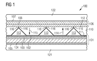
- Fig. 1 shows a composite component 100 for a wind turbine blade, wherein the composite material 100 comprises a stack 101, a membrane 110 and optionally a further stack 106.
- the stack 101 comprises at least one fibre layer 102, 103, 105.
- the stack may comprise optionally a core material 104 which may be interposed between the respective fibre layers 103, 105.
- the membrane 110 is shown schematically with a large thickness in order to outline the perforation with openings 113.
- the membrane 110 may comprise the thickness of the fibre layer 102, 103, 105 or may comprise a smaller thickness than the fibre layer 102, 103, 105.
- the membrane 110 has a first surface 111 and a second surface 112 which is an opposite surface with respect to the first surface 111.
- the membrane 110 is arranged with the first surface 110 on top of the stack 101.
- the membrane 110 is perforated with openings 113 which are formed in such a way that the openings 113 are permeable for fluid (such as resin) flowing along a first direction 114 directing from the first surface 111 to the second surface 112 and which openings 113 are impermeable for a fluid (such as air) flowing along a second direction 115 directing from the second surface 112 to the first surface 111.
- fluid such as resin
- a further stack 106 is optionally arranged on the second surface 112 of the membrane 110.
- the further stack 106 may comprise further fibre layers 107, 108.
- the stack 101 which may comprise the fibre layers 102, 103, 105 and for example a core material 104 may be arranged onto a surface of the mould 121.
- the stack 101 is covered by the membrane 110.
- the fibre layers 102, 103, 105, 107, 108 and the membrane 110 are dry and also movable with respect to each other.
- an underpressure is applied between the membrane 110 and the mould 121 for pressing and thus fixing the membrane 110 and the stack 101 to the mould 121.
- the membrane 110 In order to support the generation of the underpressure between the membrane 110 and the mould 121, the membrane 110 is aligned in such a way that fluid (such as air) is not flowable along the second direction 115 from the surroundings of the membrane 110 to the inner surface of the mould 121. Hence, the membrane 110 functions as a barrier layer for the fluid (air) and is almost airtight. Hence, a proper and temporary fixation of the membrane 110 and the stack 101 onto the mould 121 is achieved.
- fluid such as air
- the composite component 100 is fixed between the mould 121 and the further mould 122. If the stack 101, the further stack 106 and the membrane 110 are clamped and thus fixed between the mould 121 and the further mould 122, a transfer moulding procedure may be started. Hence, a fluid, such as a resin, is injected between the mould 121 and the further mould 122. In particular, the resin is injected starting from the mould 121 along the first direction 114 through the stack 101.
- a fluid such as a resin
- the resin may flow through the openings 113 such that the fibre layers 102, 103, 105, the membrane 110 itself and optionally the further fibre layers 107, 108 are homogeneously soaked and wetted with the resin.
- the membrane 110 does not function as a barrier layer for the fluid (resin) flowing along the first direction 114.
- the composite component 100 may be cured by applying curing temperature (if necessary) to the composite material 100.
- the membrane 110 may comprise elastic seal lips 116 surrounding the openings 113 at the second surface 112. If a fluid flows along the second direction 115, the seal lip 116 surrounding an opening 113 is pressed together such that the opening 113 is impermeable for the fluid. If the fluid flows along the first direction 114, the seal lip 116 is elastically deformed and edges of the seal lip 116 are bent away, such that the fluid is flowable through the openings 113 along the first direction 114.
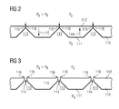
- Fig. 2 shows a detailed view of the membrane 110, wherein the openings 113 are closed by the seal lips 116 and thus impermeable for the fluid flowing along the second direction 115.
- the fluid flows along the second direction 115, if a first pressure Pa acting on the second surface 112 of the membrane 110 is higher than the second pressure Pb acting on the first surface 111 of the membrane 110.
- This situation is generated for example when applying the vacuum pump for sucking air out of a region between the membrane 100 and the mould 121.
- the openings 113 are formed with a cone-like shape.
- Fig. 2 a cross-sectional view of the membrane 100 and the openings 113 is shown.
- the cone-like shaped openings 113 have a larger base area and a smaller cone end.
- the base area is formed at the first surface 111 and the cone area is formed at the second surface 112.
- Respective seal lips 116 surrounding a respective opening 113 are formed at the cone area.
- the membrane 110 is shown in a permeable state.
- the openings 113 are opened because the edges of the seal lips 116 are bended away by the fluid acting on the seal lip 116.
- the seal lips 116 are permeable for the fluid flowing along the first direction 114.
- the fluid flows along the first direction 114, if the first pressure Pa acting on the second surface 112 of the membrane 110 is lower than the second pressure Pb acting on the first surface 111 of the membrane 110. This situation is generated for example when pressing the resin for soaking and wetting the stack 101 into a region between the membrane 100 and the mould 121.
- the membrane 110 is placable on top of the stack 101 for forming a closed barrier to air for providing a vacuum consolidation of the complete stack 101.
- the membrane 110 is permeable in order to ensure a proper soaking of the stack 101, the membrane 110 and the further stack 106.
- the membrane 110 may be made partially heterogeneous over the thickness in order to be able to react differently depending on pressure differences between the first surface 111 and the second surface 112. This is obtained by introducing valve-like, cone-shaped openings 113.
- Pb positive pressure difference from Pa to Pb
- the membrane When exposed to a positive pressure difference from Pa to Pb (Pa ⁇ Pb as shown in Fig. 2 ) the membrane is closed and (almost) vacuum tight.
- a negative pressure difference occurs (Pa ⁇ Pb, Fig. 3 ) e.g. during resin injection, the membrane 110 opens up and a flow of fluid (resin) through the openings 113 is possible.
- resin is provided at the stacks 101, 106 where resin is
- the membrane 110 may form an integrated part of the final structure of the composite component.
- the membrane 110 may form a surface layer of the composite component 100, because the membrane 110 may be sufficiently wetted and soaked with resin by the permeability properties of the membrane 110.
Landscapes
- Engineering & Computer Science (AREA)
- Mechanical Engineering (AREA)
- Chemical & Material Sciences (AREA)
- Composite Materials (AREA)
- Life Sciences & Earth Sciences (AREA)
- Sustainable Development (AREA)
- Sustainable Energy (AREA)
- Combustion & Propulsion (AREA)
- General Engineering & Computer Science (AREA)
- Casting Or Compression Moulding Of Plastics Or The Like (AREA)
- Wind Motors (AREA)
- Moulds For Moulding Plastics Or The Like (AREA)
Abstract
Description
- The present invention relates to a composite component for a wind turbine blade and to a method for manufacturing a composite component for a wind turbine blade.
- For wind turbines, in particular for wind turbine blades, stable and lightweight material is used. Specifically composite fibre components are used for the wind turbine blades due to the proper material characteristics.
- Hence, the composite component made for example for the wind turbine blades comprises several reinforced fibre layers which form a stack. The composite component is often made by using a transfer moulding process. By using the transfer moulding process, the reinforced fibre layers are stacked above each other inside a mould. The mould defines a desired shape of the fibre components to be manufactured. After arranging the composite layers into the mould, from the opposed side of the mould a further mould, such as an inflatable bag, a vacuum membrane or a stiff mould, is attached. The stack is then pressed between the mould and the further mould. In a subsequent step, the stack and the single reinforced fibre layers are wetted and soaked with resin. Next, the soaked reinforced fibre layers of the stack are cured by a predefined temperature.
- During manufacturing of the composite component, it has to be ensured that the single reinforced fibre layers are arranged in a correct position and thus form a geometrical conformity during the whole manufacturing process. In particular, the reinforced fibre layers have to be already fixed before the reinforced fibre layers are pressed and thus fixed between the respective moulds. Therefore, an underpressure or a vacuum is applied in order to soak the stack of reinforced fibre layers to one of the moulds. Thereby, the reinforced fibre layers are fixed to the respective mould.
- In order to improve the vacuum fixing of the stack to the mould, a dense fibre material layer can be placed on a surface of the stack of composite layers. The dense fibre material layer has a low permeability to air in order to establish an underpressure between the mould surface and the sealed fibre material layer in order to fix the stack which is located between the sealed fibre material layer and the mould to the mould surface. Thus, the fibre material layup can be fixated, and thereby enable further movement without the risk of displacing the fibre layup.
-
EP 2 123 431 B1 discloses to apply a vacuum distribution layer at an inner surface of the mould. The vacuum distribution layer is connected to a vacuum pump such that the vacuum pump may suck the air through the vacuum distributing layer out of the stack. - On the one hand, it is desired that the top fibre layer of the stack, which layer forms a part of the structure reinforcement of the laminate, is of a conventional type and comprises a good resin wetting property and a good interlaminate shear strength relative to any adjacent structure elements such as shells, beams, etc. On the other hand, it is desired that the top fibre layer has a low permeability such that good vacuum properties are provided. In tendency, this top fibre layer with a low permeability to air generally comprises a relatively poor resin wetting property and a low interlaminate shear strength which would be normally desirable.
- Furthermore, even with the relative low air permeability of the top fibre layer, an extremely large air flow is necessary to retain a sufficient pressure difference over the fibre layup for holding the stack to the mould surface, especially when moulding large parts like above described wind turbine blades.
- Therefore, fixating the fibre layup with other means than a dense fibre surface material can be advantageous.
- It may be an object of the present invention to provide a composite component for a wind turbine blade which is simple to manufacture.
- This object may be solved by a composite component by a wind turbine blade and by a method for manufacturing a composite component for a wind turbine blade according to the independent claims.
- According to a first aspect of the present invention a composite component for a wind turbine is presented. The composite component comprises a stack of at least one (reinforced) fibre layer and a membrane. The membrane has a first surface and a second surface which is an opposite surface with respect to the first surface. The membrane is arranged with the first surface on top of the stack.
- The membrane is perforated with openings, wherein the membrane is formed in such a way that the openings are permeable for a fluid flowing along a first direction directing from the first surface to the second surface and which openings are impermeable or less permeable for a fluid flowing along a second direction directing from the second surface to the first surface.
- According to a further aspect of the present invention a method for manufacturing a composite component for a wind turbine blade is presented. According to the method, a membrane is arranged with the first surface on top of the stack of at least one (reinforced) fibre layer. The membrane is perforated with openings which are formed in such a way that the openings are permeable for a fluid flowing along a first direction directing from the first surface to a second surface which is an opposite surface with respect to the first surface. Furthermore, the openings are formed in such a way that the openings are impermeable or less permeable for a fluid flowing along a second direction directing from the second surface to the first surface.
- The stack comprises at least one fibre layer. The fibre layer may be made of fibres which are unidirectional or multidirectional aligned with respect to each other. The fibres of a layer may also form a woven fabric and a prepreg, for example. Each fibre layer of the stack may be made of different materials and may comprise different material characteristics. For example, the fibre may be made of carbon fibres, glass fibres or other reinforced fibres. Furthermore, the stack may comprise a core layer which comprises a core material which may be for example a balsa wood material.
- The fluid may be a gaseous or a liquid fluid, such as air or resin, for example. In particular, the fluid which flows along the first direction through the openings may be resin, whereas the fluid flowing along the second direction may be air, for example.
- The resin may be for example, but not limited to, unsaturated polyester or epoxy. The resin may comprise for example components of styrene, acrylate, methacrylate or a diluent, for example.
- The membrane may be made of a synthetic plastic material, such as polystyrene or the like. The permeability of the membrane is provided by a perforation of the membrane with openings. The openings are formed in such a way, that a fluid flowing along a fist direction directing from the first surface to the second surface may flow through the membrane. Furthermore, the openings are formed in such a way that a fluid which flows along a second direction is prevented from flowing through the openings.
- Hence, the membrane combines the desired effects that on the one side the resin as a first fluid may flow through the membrane and on the other side air as a second fluid is blocked or hindered from flowing through the membrane in a second direction. Hence, a proper resin distribution is formed and simultaneously a good fixation of the composite component onto a mould by applying underpressure is achieved.
- By arranging the membrane on top of the stack which is arranged onto a surface of the mould, a (almost) closed barrier to air for a vacuum consolidation of the stack is achieved. Hence, between the membrane and the mould surface an underpressure may be generated efficiently by arranging the membrane in such a way that the stack and the membrane are fixed by the underpressure to the membrane until the dry stack and the dry membrane are fixed to the mould by a counterpart of a further mould in order to prevent a misalignment of the fibre layers of the stack and the membrane.
- However, if the mould and the stack and the membrane fixed thereon by underpressure are moved in a final position, resin is injected in order to soak the stack and the membrane with the resin. The resin may be pressed through the stack and the membrane along the first direction such that the membrane is permeable and the resin is flowable through the stacks and the membrane such that comprehensive supply of the resin to all desired layers and the membrane is ensured.
- In other words, the membrane is impermeable when a fluid flows along a second direction and is permeable when a fluid flows along the first direction and thereby allowing flow through the membrane in a resin soaking process step. Hence, by the present invention a composite component, in particular for a wind turbine blade, is provided, wherein the composite component comprises a membrane which may form finally an integrated surface layer of the composite component, wherein the membrane has a sufficiently low permeability to ensure a vacuum and underpressure consolidation during manufacturing and handling before wetting and soaking of the stack by resin and which can form a part of and be integrated with the complete finished composite component.
- In other words, by using the above described membrane which is permeable depending on the first and the second direction a manufacturing process is enabled where adjoining two or more fibre layers may be positioned under a vacuum while still allowing a resin flow.
- According to a further exemplary embodiment, the composite component further comprises a further stack with at least one further fibre layer arranged on the second surface of the membrane. Hence, the membrane may be an intermediate layer between the stack and the further stack. Thereby, in a first manufacturing step, the membrane may fix the stack to the mould while applying an underpressure. Next, the further stack may be applied to the second surface of the membrane. In a subsequent step, resin may be injected through the stack (along the first direction) further through the membrane and further to the further stack. Hence, a proper wetting of the further stack with resin in one manufacturing process step is possible.
- According to a further exemplary embodiment, the membrane comprises a degradable material. Although the membrane may be a part of the finished composite component, it may alternatively be possible to apply the membrane with a degradable material, so that after the applying of underpressure and after wetting and soaking the fibre layers with resin, the membrane is degraded in a subsequent method step. For example, after the stack and/or the further stack is soaked with resin, the membrane may be degraded by initiating a decomposing agent, such as styrene, acrylate, methacrylate etc. and/or by heating the degradable membrane to a temperature above a predetermined (e.g. melting) temperature. Furthermore, the membrane may be exposed to a predefined degrading light, such as infrared light etc.
- According to a further exemplary embodiment, the membrane comprises an elastic seal lip surrounding the at least one of the openings at the second surface. According to a further exemplary embodiment, the respective elastic seal lip is formed such that the respective seal lip closes the respective opening if a second pressure of the fluid applied at the first surface is lower than a first pressure of the fluid applied at the second surface and the respective seal lip open the respective opening if a second pressure of the fluid applied at the first surface is higher than the first pressure of the fluid applied at the second surface.
- Hence, by applying elastic seal lips around in particular an edge of the respective openings at the second surface, the lips may be elastically deformable by the fluid (pressure) acting thereon, such that fluid may flow through or not flow through the openings.
- According to a further exemplary embodiment, at least one of the openings has a cone-like shape with a base area and a cone end, wherein the base area is formed at the first surface and the cone area is formed at the second surface. The respective seal lip is formed at the cone area.
- Hence, by providing a cone-like shape of the openings, the fluid which is pressed along the first direction enters the openings through the larger base area. When moving further from the base area along the first direction to the cone ends, the fluid inside the openings is concentrated at the seal lips due to the decreasing diameter. Hence, the seal lips opens such that the fluid can flow through the open openings. If the fluid is pressed along the second direction, the fluid is pressed against the seal lip, wherein the seal lip is not bendable inside the opening, such that the opening stays closed.
- In the following, the manufacturing method for manufacturing the composite component with the above described membrane is described in more detail:
- The stack and the membrane are first of all arranged onto a mould surface of a mould. The mould surface forms a negative form of the composite component (e.g. a wind turbine blade) to be finally manufactured. The stack comprising at least one fibre layer is arranged onto the surface of the mould. Above the stack, the membrane is arranged.
- Next, an underpressure between the membrane and the mould is applied, e.g. by a vacuum pump, such that the membrane and the stack are pressed against the surface of the mould, so that the membrane and the stack are fixed to the surface of the mould. The membrane is orientated in such a way, that if the underpressure is applied, no or very little air is flowable along the second direction through the opening such that the membrane is almost impermeable for air when applying underpressure between the membrane and the mould surface.
- Next, the mould may be moved to a desired position. During a movement of the mould, a misalignment of the stack and the membrane is prevented due to the fixation to the surface of the mould by the applied underpressure.
- Additionally, a further stack of at least one further fibre layer may be arranged onto a second surface of the membrane.
- Next, a further mould, such as a mould core and optionally an inflatable bag, is applied such that the stack, the membrane and optionally the further stack are located between the further mould and the mould. Hence, the stack, the further stack and the membrane are clamped between the further mould and the mould, so that a misalignment of the stack, the further stack and the membrane is prevented.
- In the next step, resin is injected via a pressure difference through the at least one fibre layer of the stack, the membrane and optionally through the further stack along the first direction. Hence, during the injection of the resin along the first direction, the membrane is permeable, so that a resin flow is provided through the stack, the membrane and optionally the further stack. Hence, all elements of the composite components between the mould and the further mould are homogeneously soaked with resin, because the membrane does not function as a barrier for the resin.
- Optionally, the membrane may be degraded after or before the resin is injected. The membrane may be degraded by a physical (e.g. light, heating) or a chemical (such as predefined solvent dilution) degradation of the membrane.
- Finally, the composite component is cured under a predefined temperature and the mould is removable from the finished composite component.
- The above described composite component may form a complete or a part of a wind turbine component, such as a wind turbine blade.
- It has to be noted that embodiments of the invention have been described with reference to different subject matters. In particular, some embodiments have been described with reference to apparatus type claims whereas other embodiments have been described with reference to method type claims. However, a person skilled in the art will gather from the above and the following description that, unless otherwise notified, in addition to any combination of features belonging to one type of subject matter also any combination between features relating to different subject matters, in particular between features of the apparatus type claims and features of the method type claims is considered as to be disclosed with this application.
- The aspects defined above and further aspects of the present invention are apparent from the examples of embodiment to be described hereinafter and are explained with reference to the examples of embodiment. The invention will be described in more detail hereinafter with reference to examples of embodiment but to which the invention is not limited.
-
Fig. 1 shows a schematical view of a layer structure of a composite component between two moulds according to an exemplary embodiment of the present invention; -
Fig. 2 shows schematically a membrane in an impermeable state according to an exemplary embodiment of the present invention; and -
Fig. 3 shows a schematical view of a membrane in a permeable state according to an exemplary embodiment of the present invention. - The illustrations in the drawings are schematical. It is noted that in different figures, similar or identical elements are provided with the same reference signs.
-
Fig. 1 shows acomposite component 100 for a wind turbine blade, wherein thecomposite material 100 comprises astack 101, amembrane 110 and optionally afurther stack 106. Thestack 101 comprises at least onefibre layer core material 104 which may be interposed between the respective fibre layers 103, 105. - In
Fig. 1 to Fig. 3 , in particular themembrane 110 is shown schematically with a large thickness in order to outline the perforation withopenings 113. However, themembrane 110 may comprise the thickness of thefibre layer fibre layer - The
membrane 110 has afirst surface 111 and asecond surface 112 which is an opposite surface with respect to thefirst surface 111. Themembrane 110 is arranged with thefirst surface 110 on top of thestack 101. - The
membrane 110 is perforated withopenings 113 which are formed in such a way that theopenings 113 are permeable for fluid (such as resin) flowing along afirst direction 114 directing from thefirst surface 111 to thesecond surface 112 and whichopenings 113 are impermeable for a fluid (such as air) flowing along asecond direction 115 directing from thesecond surface 112 to thefirst surface 111. - A
further stack 106 is optionally arranged on thesecond surface 112 of themembrane 110. Thefurther stack 106 may comprisefurther fibre layers - As can be taken from
Fig. 1 , thestack 101 which may comprise the fibre layers 102, 103, 105 and for example acore material 104 may be arranged onto a surface of themould 121. Thestack 101 is covered by themembrane 110. At this step, the fibre layers 102, 103, 105, 107, 108 and themembrane 110 are dry and also movable with respect to each other. In order to prevent an undesired relative movement e.g. between thestack 101 and themembrane 110, an underpressure is applied between themembrane 110 and themould 121 for pressing and thus fixing themembrane 110 and thestack 101 to themould 121. - In order to support the generation of the underpressure between the
membrane 110 and themould 121, themembrane 110 is aligned in such a way that fluid (such as air) is not flowable along thesecond direction 115 from the surroundings of themembrane 110 to the inner surface of themould 121. Hence, themembrane 110 functions as a barrier layer for the fluid (air) and is almost airtight. Hence, a proper and temporary fixation of themembrane 110 and thestack 101 onto themould 121 is achieved. - After positioning the
mould 121 at the desired location and/or after locating afurther mould 121 onto themembrane 110 or onto thefurther stack 106, thecomposite component 100 is fixed between themould 121 and thefurther mould 122. If thestack 101, thefurther stack 106 and themembrane 110 are clamped and thus fixed between themould 121 and thefurther mould 122, a transfer moulding procedure may be started. Hence, a fluid, such as a resin, is injected between themould 121 and thefurther mould 122. In particular, the resin is injected starting from themould 121 along thefirst direction 114 through thestack 101. Because theopenings 113 are permeable for the resin flowing along thefirst direction 114, the resin may flow through theopenings 113 such that the fibre layers 102, 103, 105, themembrane 110 itself and optionally thefurther fibre layers membrane 110 does not function as a barrier layer for the fluid (resin) flowing along thefirst direction 114. - After the
stack 101, themembrane 110 and optionally thefurther stack 106 is soaked sufficiently with resin, thecomposite component 100 may be cured by applying curing temperature (if necessary) to thecomposite material 100. - The
membrane 110 may compriseelastic seal lips 116 surrounding theopenings 113 at thesecond surface 112. If a fluid flows along thesecond direction 115, theseal lip 116 surrounding anopening 113 is pressed together such that theopening 113 is impermeable for the fluid. If the fluid flows along thefirst direction 114, theseal lip 116 is elastically deformed and edges of theseal lip 116 are bent away, such that the fluid is flowable through theopenings 113 along thefirst direction 114. -
Fig. 2 shows a detailed view of themembrane 110, wherein theopenings 113 are closed by theseal lips 116 and thus impermeable for the fluid flowing along thesecond direction 115. As can be taken fromFig. 2 , the fluid flows along thesecond direction 115, if a first pressure Pa acting on thesecond surface 112 of themembrane 110 is higher than the second pressure Pb acting on thefirst surface 111 of themembrane 110. This situation is generated for example when applying the vacuum pump for sucking air out of a region between themembrane 100 and themould 121. - The
openings 113 are formed with a cone-like shape. InFig. 2 , a cross-sectional view of themembrane 100 and theopenings 113 is shown. The cone-like shapedopenings 113 have a larger base area and a smaller cone end. The base area is formed at thefirst surface 111 and the cone area is formed at thesecond surface 112.Respective seal lips 116 surrounding arespective opening 113 are formed at the cone area. - In
Fig. 3 , themembrane 110 is shown in a permeable state. Theopenings 113 are opened because the edges of theseal lips 116 are bended away by the fluid acting on theseal lip 116. Hence, theseal lips 116 are permeable for the fluid flowing along thefirst direction 114. As can be taken fromFig. 3 , the fluid flows along thefirst direction 114, if the first pressure Pa acting on thesecond surface 112 of themembrane 110 is lower than the second pressure Pb acting on thefirst surface 111 of themembrane 110. This situation is generated for example when pressing the resin for soaking and wetting thestack 101 into a region between themembrane 100 and themould 121. - Summarizing, the
membrane 110 is placable on top of thestack 101 for forming a closed barrier to air for providing a vacuum consolidation of thecomplete stack 101. On the other side, themembrane 110 is permeable in order to ensure a proper soaking of thestack 101, themembrane 110 and thefurther stack 106. Themembrane 110 may be made partially heterogeneous over the thickness in order to be able to react differently depending on pressure differences between thefirst surface 111 and thesecond surface 112. This is obtained by introducing valve-like, cone-shapedopenings 113. When exposed to a positive pressure difference from Pa to Pb (Pa ≥ Pb as shown inFig. 2 ) the membrane is closed and (almost) vacuum tight. However, when a negative pressure difference occurs (Pa ≤ Pb,Fig. 3 ) e.g. during resin injection, themembrane 110 opens up and a flow of fluid (resin) through theopenings 113 is possible. Hence, resin is provided at thestacks - The
membrane 110 may form an integrated part of the final structure of the composite component. Themembrane 110 may form a surface layer of thecomposite component 100, because themembrane 110 may be sufficiently wetted and soaked with resin by the permeability properties of themembrane 110. - It should be noted that the term "comprising" does not exclude other elements or steps and "a" or "an" does not exclude a plurality. Also elements described in association with different embodiments may be combined. It should also be noted that reference signs in the claims should not be construed as limiting the scope of the claims.
Claims (12)
- Composite component (100) for a wind turbine blade, the composite component (100) comprising
a stack (101) of at least one fibre layer (102, 103, 105), and
a membrane (110) which has a first surface (111) and a second surface (112) which is an opposite surface with respect to the first surface (111),
wherein the membrane (110) is arranged with the first surface (111) on top of the stack (101),
wherein the membrane (110) is perforated with openings (113), wherein the membrane is formed in such a way that the openings (113) are
permeable for a fluid flowing along a first direction (114) directing from the first surface (111) to the second surface (112), and
impermeable for a fluid flowing along a second direction (115) directing from the second surface (112) to the first surface (111). - Composite component (100) according to claim 1, further comprising
a further stack (106) with at least one further fibre layer (107, 108) arranged on the second surface (112) of the membrane (110). - Composite component (100) according to claim 1 or 2,
wherein the membrane (110) comprises a degradable material. - Composite component (100) according to one of the claims 1 to 3,
wherein the membrane (110) comprises at least one elastic seal lip (116) surrounding one of the openings (113) at the second surface (112). - Composite component (100) according to claim 4,
wherein the elastic seal lip (116) is formed such that the seal lip (116) closes the respective opening (113) if a second pressure (Pb) of the fluid applied at the first surface (111) is lower than a first pressure (Pa) of the fluid applied at the second surface (112), and
the seal lip (116) opens the respective opening (113) if the second pressure (Pb) of the fluid applied at the first surface (111) is higher than the first pressure (Pa) of the fluid applied at the second surface (112). - Composite component (100) according to claim 4 or 5,
wherein at least one of the openings (113) has a cone-like shape with a base area and a cone end,
wherein the base area is formed at the first surface (111) and the cone area is formed at the second surface (112),
wherein the seal lip (116) is formed at the cone area. - Method for manufacturing a composite component (100) for a wind turbine blade, wherein the composite component (100) comprises a membrane (110) and a stack (101) of at least one fibre layer (102, 103, 105),
the method comprising
arranging the membrane (110) with a first surface (111) on top of the stack (101),
wherein the membrane (110) has a second surface (112) which is an opposite surface with respect to the first surface (111),
wherein the membrane (110) is perforated with openings (113), wherein the membrane is formed in such a way that the openings (113) are
permeable for a fluid flowing along a first direction (114) directing from the first surface (111) to the second surface (112), and
impermeable for a fluid flowing along a second direction (115) directing from the second surface (112) to the first surface (111). - Method according to claim 7,
arranging a further stack (106) of at least one further fibre layer (107, 108) onto the second surface (112) of the membrane (110). - Method according to claim 7 or 8,
arranging the stack (101) and the membrane (110) into a mould (121), and
applying an underpressure between the membrane (110) and the mould (121) such that the membrane (110) and the stack (101) are pressed against the mould (121). - Method according to one of the claims 7 to 9,
applying a further mould (122) such that the stack (101) and the membrane (110) is located between the mould (121) and the further mould (122). - Method according to one of the claims 7 to 10, injecting resin through the at least one fibre layer (102, 103, 105) of the stack (101) and the membrane (110) along the first direction (114).
- Method according to one of the claims 7 to 11,
degrading the membrane (110) by a physical and/or chemical degradation of the membrane (110).
Priority Applications (4)
| Application Number | Priority Date | Filing Date | Title |
|---|---|---|---|
| DK13166234.8T DK2799215T3 (en) | 2013-05-02 | 2013-05-02 | Perforated vacuum membrane for fiber reinforced laminates |
| EP13166234.8A EP2799215B1 (en) | 2013-05-02 | 2013-05-02 | Perforated vacuum membrane for fibre reinforced laminates |
| US14/262,717 US9957949B2 (en) | 2013-05-02 | 2014-04-26 | Perforated vacuum membrane for fibre reinforced laminates |
| CN201410179696.9A CN104129082B (en) | 2013-05-02 | 2014-04-30 | For the vacuum diaphragm of the perforation of fiber reinforced laminate |
Applications Claiming Priority (1)
| Application Number | Priority Date | Filing Date | Title |
|---|---|---|---|
| EP13166234.8A EP2799215B1 (en) | 2013-05-02 | 2013-05-02 | Perforated vacuum membrane for fibre reinforced laminates |
Publications (2)
| Publication Number | Publication Date |
|---|---|
| EP2799215A1 true EP2799215A1 (en) | 2014-11-05 |
| EP2799215B1 EP2799215B1 (en) | 2018-09-19 |
Family
ID=48193184
Family Applications (1)
| Application Number | Title | Priority Date | Filing Date |
|---|---|---|---|
| EP13166234.8A Not-in-force EP2799215B1 (en) | 2013-05-02 | 2013-05-02 | Perforated vacuum membrane for fibre reinforced laminates |
Country Status (4)
| Country | Link |
|---|---|
| US (1) | US9957949B2 (en) |
| EP (1) | EP2799215B1 (en) |
| CN (1) | CN104129082B (en) |
| DK (1) | DK2799215T3 (en) |
Families Citing this family (4)
| Publication number | Priority date | Publication date | Assignee | Title |
|---|---|---|---|---|
| CN107405851B (en) * | 2015-04-21 | 2019-10-22 | 耐克创新有限合伙公司 | Capsule-like element formed from three sheets and method of making a pouch-like element |
| DE102015115793A1 (en) | 2015-09-18 | 2017-03-23 | Airbus Defence and Space GmbH | Production of objects with fiber-reinforced area |
| AU2016222309B2 (en) | 2016-08-29 | 2022-09-29 | The Boeing Company | Actuatable flow media |
| DE102017108902A1 (en) * | 2017-04-26 | 2018-10-31 | Wobben Properties Gmbh | Method for the simultaneous production of two or more fiber composite components and fiber composite component |
Citations (4)
| Publication number | Priority date | Publication date | Assignee | Title |
|---|---|---|---|---|
| DE10013409C1 (en) * | 2000-03-17 | 2000-11-23 | Daimler Chrysler Ag | Vacuum injection process for manufacturing fiber reinforced composite products involves evacuating second chamber causing resin to flow into preform in adjacent evacuated first chamber |
| WO2007098769A1 (en) * | 2006-03-03 | 2007-09-07 | Lm Glasfiber A/S | Method and apparatus for providing polymer to be used at vacuum infusion |
| EP2123431B1 (en) | 2008-05-21 | 2011-03-02 | Siemens Aktiengesellschaft | Method for manufacturing a composite |
| EP2604413A1 (en) * | 2011-12-12 | 2013-06-19 | Stevik SAS | Multi-layered sheet for vacuum moulding |
Family Cites Families (46)
| Publication number | Priority date | Publication date | Assignee | Title |
|---|---|---|---|---|
| US3399822A (en) * | 1967-08-01 | 1968-09-03 | Kugler Emanuel | Plastic bag |
| US4124678A (en) * | 1975-04-11 | 1978-11-07 | Sipler Plastics, Inc. | Method of making tortuous tubular articles |
| US4132755A (en) * | 1977-07-22 | 1979-01-02 | Jay Johnson | Process for manufacturing resin-impregnated, reinforced articles without the presence of resin fumes |
| US5108532A (en) * | 1988-02-02 | 1992-04-28 | Northrop Corporation | Method and apparatus for shaping, forming, consolidating and co-consolidating thermoplastic or thermosetting composite products |
| US4902215A (en) * | 1988-06-08 | 1990-02-20 | Seemann Iii William H | Plastic transfer molding techniques for the production of fiber reinforced plastic structures |
| US4942013A (en) * | 1989-03-27 | 1990-07-17 | Mcdonnell Douglas Corporation | Vacuum resin impregnation process |
| US5052906A (en) * | 1989-03-30 | 1991-10-01 | Seemann Composite Systems, Inc. | Plastic transfer molding apparatus for the production of fiber reinforced plastic structures |
| GB9004428D0 (en) * | 1990-02-28 | 1990-04-25 | Middleton Nigel John | Fabric |
| US5181287A (en) * | 1992-03-18 | 1993-01-26 | Jun Jie Yang | Heat-venting insulating article |
| US5439635A (en) * | 1993-02-18 | 1995-08-08 | Scrimp Systems, Llc | Unitary vacuum bag for forming fiber reinforced composite articles and process for making same |
| US5787502A (en) * | 1994-02-17 | 1998-08-04 | Middleton; Nigel John | Thermoinsulative protective garments |
| US6508974B1 (en) * | 1996-02-15 | 2003-01-21 | David Loving | Process for fiberglass molding using a vacuum |
| US20040017020A1 (en) * | 2002-07-26 | 2004-01-29 | David Loving | Process for fiberglass molding using a vacuum |
| US6048488A (en) * | 1997-04-04 | 2000-04-11 | The United States Of America As Represented By The Secretary Of The Army | One-step resin transfer molding of multifunctional composites consisting of multiple resins |
| GB2360483A (en) * | 2000-03-02 | 2001-09-26 | Slingsby Aviat Ltd | Improvements in the manufacture of resin-impregnated components |
| US6818159B2 (en) | 2000-03-17 | 2004-11-16 | Deutsches Zentrum Fuer Luft-Und Raumfahrt E.V. | Process for the production of a composite consisting of a fiber reinforced material |
| CA2635751A1 (en) * | 2000-06-01 | 2001-12-06 | Irene Lin | Method for manufacturing an air permeable composite film |
| KR20020086473A (en) * | 2001-01-26 | 2002-11-18 | 가네가후치 가가쿠 고교 가부시키가이샤 | Fiber reinforced plastic composite structure core material and fiber reinforced plastic composite structure manufacturing method using said core material |
| DE10105976C2 (en) * | 2001-02-09 | 2003-05-22 | Deutsch Zentr Luft & Raumfahrt | Method and device for producing large-area components made of fiber composite materials |
| GB0112541D0 (en) * | 2001-05-23 | 2001-07-11 | Structural Polymer Systems Ltd | Surface material |
| US7048985B2 (en) * | 2001-07-23 | 2006-05-23 | Vrac, Llc | Three-dimensional spacer fabric resin infusion media and reinforcing composite lamina |
| US6630095B2 (en) * | 2001-08-01 | 2003-10-07 | Lockheed Martin Corporation | Method for making composite structures |
| US6627142B2 (en) * | 2001-08-01 | 2003-09-30 | Lockheed Martin Corporation | Apparatus for making composite structures and method for making same |
| FR2828131A1 (en) * | 2001-08-06 | 2003-02-07 | Pole De Plasturgie De L Est | Manufacture of large components from resin-impregnated composition materials by Resin Transfer Molding (RTM) and frontal injection |
| US6964561B2 (en) * | 2002-04-23 | 2005-11-15 | V System Composites, Inc. | High-performance infusion system for VARTM fabrication |
| ES2727872T3 (en) * | 2002-10-09 | 2019-10-21 | Toray Industries | RTM Molding Method |
| US6957744B2 (en) * | 2003-01-24 | 2005-10-25 | Insta-Mix, Inc. | Nipple with multiple pinholes for baby bottle assembly |
| US7686608B2 (en) * | 2003-08-14 | 2010-03-30 | Lockheed-Martin Corporation | Apparatus and methods for distributing a substance |
| US7461892B2 (en) * | 2003-12-01 | 2008-12-09 | W.E.T. Automotive Systems, A.C. | Valve layer for a seat |
| FR2868008B1 (en) * | 2004-03-24 | 2006-05-12 | Diatex Sa | MULTILAYER COMPLEX AND PROCESS FOR MANUFACTURING A COMPOSITE MATERIAL PART USING SUCH A COMPLEX |
| US20050281980A1 (en) * | 2004-06-22 | 2005-12-22 | Cruz Jose A | Vacuum pressure bag for use with large scale composite structures |
| US7871682B2 (en) * | 2004-09-23 | 2011-01-18 | The United States Of America As Represented By The Administrator Of The National Aeronautics And Space Administration | Support assembly for composite laminate materials during roll press processing |
| DK176135B1 (en) * | 2004-11-30 | 2006-09-18 | Lm Glasfiber As | Vacuum infusion using semipermeable membrane |
| WO2007038930A1 (en) * | 2005-10-04 | 2007-04-12 | Lm Glasfiber A/S | A method for producing a fibre-reinforced product |
| FR2894991B1 (en) * | 2005-12-15 | 2008-01-18 | Chomarat Composites Soc Par Ac | TEXTILE COMPLEX FOR USE AS A REINFORCING LAYER FOR THE MANUFACTURE OF COMPOSITE PARTS, AND METHOD FOR MANUFACTURING SUCH COMPLEX |
| GB0606045D0 (en) * | 2006-03-25 | 2006-05-03 | Hexcel Composites Ltd | A thermoplastic toughening material |
| DE602006000870T2 (en) | 2006-05-26 | 2009-05-14 | Siemens Aktiengesellschaft | Method and article for molding a component by transfer molding of resin (R.T.M.), wherein the molding at least partially contains a fiber-reinforced laminate |
| GB0702781D0 (en) * | 2007-02-13 | 2007-03-21 | Airbus Uk Ltd | Method of processing a composite material |
| EP1990178B1 (en) * | 2007-05-07 | 2010-07-21 | Siemens Aktiengesellschaft | Method for producing a wind turbine rotor blade |
| US8153231B2 (en) * | 2007-09-24 | 2012-04-10 | Tredegar Film Products Corporation | Thin web |
| FR2934808B1 (en) * | 2008-08-08 | 2013-03-08 | Airbus France | METHOD FOR MANUFACTURING A COMPOSITE MATERIAL PART AND ASSOCIATED DEVICE |
| FR2948600B1 (en) * | 2009-07-28 | 2011-10-07 | Airbus Operations Sas | PROCESS FOR MANUFACTURING AN AIRCRAFT PIECE BY RESIN INFUSION |
| US8940213B2 (en) * | 2010-06-25 | 2015-01-27 | The Boeing Company | Resin infusion of composite parts using a perforated caul sheet |
| US9682514B2 (en) * | 2010-06-25 | 2017-06-20 | The Boeing Company | Method of manufacturing resin infused composite parts using a perforated caul sheet |
| US9044904B2 (en) * | 2011-11-17 | 2015-06-02 | The Boeing Company | Expandable surface breather and method |
| EP2607059A1 (en) * | 2011-12-23 | 2013-06-26 | Siemens Aktiengesellschaft | Method for manufacturing a composite using a degradable membrane |
-
2013
- 2013-05-02 DK DK13166234.8T patent/DK2799215T3/en active
- 2013-05-02 EP EP13166234.8A patent/EP2799215B1/en not_active Not-in-force
-
2014
- 2014-04-26 US US14/262,717 patent/US9957949B2/en not_active Expired - Fee Related
- 2014-04-30 CN CN201410179696.9A patent/CN104129082B/en not_active Expired - Fee Related
Patent Citations (4)
| Publication number | Priority date | Publication date | Assignee | Title |
|---|---|---|---|---|
| DE10013409C1 (en) * | 2000-03-17 | 2000-11-23 | Daimler Chrysler Ag | Vacuum injection process for manufacturing fiber reinforced composite products involves evacuating second chamber causing resin to flow into preform in adjacent evacuated first chamber |
| WO2007098769A1 (en) * | 2006-03-03 | 2007-09-07 | Lm Glasfiber A/S | Method and apparatus for providing polymer to be used at vacuum infusion |
| EP2123431B1 (en) | 2008-05-21 | 2011-03-02 | Siemens Aktiengesellschaft | Method for manufacturing a composite |
| EP2604413A1 (en) * | 2011-12-12 | 2013-06-19 | Stevik SAS | Multi-layered sheet for vacuum moulding |
Also Published As
| Publication number | Publication date |
|---|---|
| DK2799215T3 (en) | 2019-01-14 |
| US20140328690A1 (en) | 2014-11-06 |
| CN104129082A (en) | 2014-11-05 |
| US9957949B2 (en) | 2018-05-01 |
| EP2799215B1 (en) | 2018-09-19 |
| CN104129082B (en) | 2018-07-10 |
Similar Documents
| Publication | Publication Date | Title |
|---|---|---|
| US9234500B2 (en) | Method of producing a composite shell structure | |
| US8877116B2 (en) | Method of manufacturing a wind turbine blade shell part comprising a magnetisable material | |
| EP1996389B1 (en) | Method and apparatus for providing polymer to be used at vacuum infusion | |
| DK2909013T3 (en) | APPARATUS AND PROCEDURE FOR MANUFACTURING A ROTOR SHEET BELT | |
| EP2540482A1 (en) | Method for manufacturing composite cylindrical body, method for molding fiber-reinforced resin molded object and molded object | |
| US9108376B2 (en) | Method for making a wind turbine rotor blade half shell or wind turbine rotor blade and production mold therefor | |
| JP2009528195A5 (en) | ||
| EP2228198A1 (en) | A method of strengthening a wind turbine blade and the strengthened blade | |
| US9957949B2 (en) | Perforated vacuum membrane for fibre reinforced laminates | |
| CN104736312A (en) | Mold, control device, method and apparatus for producing preferably fibre-reinforced plastic components | |
| US20150283765A1 (en) | Supporting profiled element, method for producing a supporting profiled element, and use of said supporting profiled element in a method for producing a reinforced vehicle fuselage component | |
| EP3711938B1 (en) | Manufacturing a wind turbine blade shell part and root end assembly for a wind turbine blade shell part | |
| CN104890254B (en) | Method for manufacturing a component of a wind turbine | |
| EP2607059A1 (en) | Method for manufacturing a composite using a degradable membrane | |
| EP3894192B1 (en) | Method for manufacturing a fiber reinforced polymer composite beam, particularly a spar beam for a wind turbine rotor blade | |
| JP2007118577A (en) | Manufacturing method and manufacturing apparatus for fiber reinforced resin member | |
| EP2873516A1 (en) | Method and arrangement for manufacturing a composite material component | |
| JP2020515435A (en) | Tools for manufacturing complex components | |
| WO2025140762A1 (en) | Method for repairing wind turbine blades | |
| JP2020116771A (en) | Molding method |
Legal Events
| Date | Code | Title | Description |
|---|---|---|---|
| PUAI | Public reference made under article 153(3) epc to a published international application that has entered the european phase |
Free format text: ORIGINAL CODE: 0009012 |
|
| 17P | Request for examination filed |
Effective date: 20130502 |
|
| AK | Designated contracting states |
Kind code of ref document: A1 Designated state(s): AL AT BE BG CH CY CZ DE DK EE ES FI FR GB GR HR HU IE IS IT LI LT LU LV MC MK MT NL NO PL PT RO RS SE SI SK SM TR |
|
| AX | Request for extension of the european patent |
Extension state: BA ME |
|
| R17P | Request for examination filed (corrected) |
Effective date: 20150504 |
|
| RBV | Designated contracting states (corrected) |
Designated state(s): AL AT BE BG CH CY CZ DE DK EE ES FI FR GB GR HR HU IE IS IT LI LT LU LV MC MK MT NL NO PL PT RO RS SE SI SK SM TR |
|
| RAP1 | Party data changed (applicant data changed or rights of an application transferred) |
Owner name: SIEMENS AKTIENGESELLSCHAFT |
|
| STAA | Information on the status of an ep patent application or granted ep patent |
Free format text: STATUS: EXAMINATION IS IN PROGRESS |
|
| 17Q | First examination report despatched |
Effective date: 20171109 |
|
| GRAP | Despatch of communication of intention to grant a patent |
Free format text: ORIGINAL CODE: EPIDOSNIGR1 |
|
| STAA | Information on the status of an ep patent application or granted ep patent |
Free format text: STATUS: GRANT OF PATENT IS INTENDED |
|
| RIC1 | Information provided on ipc code assigned before grant |
Ipc: B29C 70/08 20060101ALI20180326BHEP Ipc: F03D 1/06 20060101ALN20180326BHEP Ipc: B29C 70/54 20060101AFI20180326BHEP Ipc: B29C 70/44 20060101ALI20180326BHEP Ipc: B29L 31/08 20060101ALN20180326BHEP Ipc: B29C 70/48 20060101ALI20180326BHEP |
|
| RIC1 | Information provided on ipc code assigned before grant |
Ipc: F03D 1/06 20060101ALN20180412BHEP Ipc: B29C 70/44 20060101ALI20180412BHEP Ipc: B29C 70/54 20060101AFI20180412BHEP Ipc: B29L 31/08 20060101ALN20180412BHEP Ipc: B29C 70/08 20060101ALI20180412BHEP Ipc: B29C 70/48 20060101ALI20180412BHEP |
|
| INTG | Intention to grant announced |
Effective date: 20180424 |
|
| GRAS | Grant fee paid |
Free format text: ORIGINAL CODE: EPIDOSNIGR3 |
|
| GRAA | (expected) grant |
Free format text: ORIGINAL CODE: 0009210 |
|
| STAA | Information on the status of an ep patent application or granted ep patent |
Free format text: STATUS: THE PATENT HAS BEEN GRANTED |
|
| AK | Designated contracting states |
Kind code of ref document: B1 Designated state(s): AL AT BE BG CH CY CZ DE DK EE ES FI FR GB GR HR HU IE IS IT LI LT LU LV MC MK MT NL NO PL PT RO RS SE SI SK SM TR |
|
| REG | Reference to a national code |
Ref country code: GB Ref legal event code: FG4D |
|
| REG | Reference to a national code |
Ref country code: CH Ref legal event code: EP |
|
| REG | Reference to a national code |
Ref country code: AT Ref legal event code: REF Ref document number: 1042756 Country of ref document: AT Kind code of ref document: T Effective date: 20181015 |
|
| REG | Reference to a national code |
Ref country code: IE Ref legal event code: FG4D |
|
| REG | Reference to a national code |
Ref country code: DE Ref legal event code: R096 Ref document number: 602013043780 Country of ref document: DE |
|
| REG | Reference to a national code |
Ref country code: DK Ref legal event code: T3 Effective date: 20190106 |
|
| REG | Reference to a national code |
Ref country code: NL Ref legal event code: MP Effective date: 20180919 |
|
| PG25 | Lapsed in a contracting state [announced via postgrant information from national office to epo] |
Ref country code: NO Free format text: LAPSE BECAUSE OF FAILURE TO SUBMIT A TRANSLATION OF THE DESCRIPTION OR TO PAY THE FEE WITHIN THE PRESCRIBED TIME-LIMIT Effective date: 20181219 Ref country code: BG Free format text: LAPSE BECAUSE OF FAILURE TO SUBMIT A TRANSLATION OF THE DESCRIPTION OR TO PAY THE FEE WITHIN THE PRESCRIBED TIME-LIMIT Effective date: 20181219 Ref country code: GR Free format text: LAPSE BECAUSE OF FAILURE TO SUBMIT A TRANSLATION OF THE DESCRIPTION OR TO PAY THE FEE WITHIN THE PRESCRIBED TIME-LIMIT Effective date: 20181220 Ref country code: FI Free format text: LAPSE BECAUSE OF FAILURE TO SUBMIT A TRANSLATION OF THE DESCRIPTION OR TO PAY THE FEE WITHIN THE PRESCRIBED TIME-LIMIT Effective date: 20180919 Ref country code: LT Free format text: LAPSE BECAUSE OF FAILURE TO SUBMIT A TRANSLATION OF THE DESCRIPTION OR TO PAY THE FEE WITHIN THE PRESCRIBED TIME-LIMIT Effective date: 20180919 Ref country code: RS Free format text: LAPSE BECAUSE OF FAILURE TO SUBMIT A TRANSLATION OF THE DESCRIPTION OR TO PAY THE FEE WITHIN THE PRESCRIBED TIME-LIMIT Effective date: 20180919 Ref country code: SE Free format text: LAPSE BECAUSE OF FAILURE TO SUBMIT A TRANSLATION OF THE DESCRIPTION OR TO PAY THE FEE WITHIN THE PRESCRIBED TIME-LIMIT Effective date: 20180919 |
|
| REG | Reference to a national code |
Ref country code: LT Ref legal event code: MG4D |
|
| PG25 | Lapsed in a contracting state [announced via postgrant information from national office to epo] |
Ref country code: AL Free format text: LAPSE BECAUSE OF FAILURE TO SUBMIT A TRANSLATION OF THE DESCRIPTION OR TO PAY THE FEE WITHIN THE PRESCRIBED TIME-LIMIT Effective date: 20180919 Ref country code: LV Free format text: LAPSE BECAUSE OF FAILURE TO SUBMIT A TRANSLATION OF THE DESCRIPTION OR TO PAY THE FEE WITHIN THE PRESCRIBED TIME-LIMIT Effective date: 20180919 Ref country code: HR Free format text: LAPSE BECAUSE OF FAILURE TO SUBMIT A TRANSLATION OF THE DESCRIPTION OR TO PAY THE FEE WITHIN THE PRESCRIBED TIME-LIMIT Effective date: 20180919 |
|
| REG | Reference to a national code |
Ref country code: AT Ref legal event code: MK05 Ref document number: 1042756 Country of ref document: AT Kind code of ref document: T Effective date: 20180919 |
|
| PG25 | Lapsed in a contracting state [announced via postgrant information from national office to epo] |
Ref country code: PL Free format text: LAPSE BECAUSE OF FAILURE TO SUBMIT A TRANSLATION OF THE DESCRIPTION OR TO PAY THE FEE WITHIN THE PRESCRIBED TIME-LIMIT Effective date: 20180919 Ref country code: EE Free format text: LAPSE BECAUSE OF FAILURE TO SUBMIT A TRANSLATION OF THE DESCRIPTION OR TO PAY THE FEE WITHIN THE PRESCRIBED TIME-LIMIT Effective date: 20180919 Ref country code: AT Free format text: LAPSE BECAUSE OF FAILURE TO SUBMIT A TRANSLATION OF THE DESCRIPTION OR TO PAY THE FEE WITHIN THE PRESCRIBED TIME-LIMIT Effective date: 20180919 Ref country code: IS Free format text: LAPSE BECAUSE OF FAILURE TO SUBMIT A TRANSLATION OF THE DESCRIPTION OR TO PAY THE FEE WITHIN THE PRESCRIBED TIME-LIMIT Effective date: 20190119 Ref country code: IT Free format text: LAPSE BECAUSE OF FAILURE TO SUBMIT A TRANSLATION OF THE DESCRIPTION OR TO PAY THE FEE WITHIN THE PRESCRIBED TIME-LIMIT Effective date: 20180919 Ref country code: ES Free format text: LAPSE BECAUSE OF FAILURE TO SUBMIT A TRANSLATION OF THE DESCRIPTION OR TO PAY THE FEE WITHIN THE PRESCRIBED TIME-LIMIT Effective date: 20180919 Ref country code: RO Free format text: LAPSE BECAUSE OF FAILURE TO SUBMIT A TRANSLATION OF THE DESCRIPTION OR TO PAY THE FEE WITHIN THE PRESCRIBED TIME-LIMIT Effective date: 20180919 Ref country code: CZ Free format text: LAPSE BECAUSE OF FAILURE TO SUBMIT A TRANSLATION OF THE DESCRIPTION OR TO PAY THE FEE WITHIN THE PRESCRIBED TIME-LIMIT Effective date: 20180919 Ref country code: NL Free format text: LAPSE BECAUSE OF FAILURE TO SUBMIT A TRANSLATION OF THE DESCRIPTION OR TO PAY THE FEE WITHIN THE PRESCRIBED TIME-LIMIT Effective date: 20180919 |
|
| REG | Reference to a national code |
Ref country code: DE Ref legal event code: R081 Ref document number: 602013043780 Country of ref document: DE Owner name: SIEMENS GAMESA RENEWABLE ENERGY A/S, DK Free format text: FORMER OWNER: SIEMENS AKTIENGESELLSCHAFT, 80333 MUENCHEN, DE |
|
| RAP2 | Party data changed (patent owner data changed or rights of a patent transferred) |
Owner name: SIEMENS GAMESA RENEWABLE ENERGY A/S |
|
| PG25 | Lapsed in a contracting state [announced via postgrant information from national office to epo] |
Ref country code: SK Free format text: LAPSE BECAUSE OF FAILURE TO SUBMIT A TRANSLATION OF THE DESCRIPTION OR TO PAY THE FEE WITHIN THE PRESCRIBED TIME-LIMIT Effective date: 20180919 Ref country code: PT Free format text: LAPSE BECAUSE OF FAILURE TO SUBMIT A TRANSLATION OF THE DESCRIPTION OR TO PAY THE FEE WITHIN THE PRESCRIBED TIME-LIMIT Effective date: 20190119 Ref country code: SM Free format text: LAPSE BECAUSE OF FAILURE TO SUBMIT A TRANSLATION OF THE DESCRIPTION OR TO PAY THE FEE WITHIN THE PRESCRIBED TIME-LIMIT Effective date: 20180919 |
|
| REG | Reference to a national code |
Ref country code: DE Ref legal event code: R097 Ref document number: 602013043780 Country of ref document: DE |
|
| PLBE | No opposition filed within time limit |
Free format text: ORIGINAL CODE: 0009261 |
|
| STAA | Information on the status of an ep patent application or granted ep patent |
Free format text: STATUS: NO OPPOSITION FILED WITHIN TIME LIMIT |
|
| 26N | No opposition filed |
Effective date: 20190620 |
|
| REG | Reference to a national code |
Ref country code: GB Ref legal event code: 732E Free format text: REGISTERED BETWEEN 20190822 AND 20190828 |
|
| PG25 | Lapsed in a contracting state [announced via postgrant information from national office to epo] |
Ref country code: SI Free format text: LAPSE BECAUSE OF FAILURE TO SUBMIT A TRANSLATION OF THE DESCRIPTION OR TO PAY THE FEE WITHIN THE PRESCRIBED TIME-LIMIT Effective date: 20180919 |
|
| REG | Reference to a national code |
Ref country code: CH Ref legal event code: PL |
|
| PG25 | Lapsed in a contracting state [announced via postgrant information from national office to epo] |
Ref country code: CH Free format text: LAPSE BECAUSE OF NON-PAYMENT OF DUE FEES Effective date: 20190531 Ref country code: MC Free format text: LAPSE BECAUSE OF FAILURE TO SUBMIT A TRANSLATION OF THE DESCRIPTION OR TO PAY THE FEE WITHIN THE PRESCRIBED TIME-LIMIT Effective date: 20180919 Ref country code: LI Free format text: LAPSE BECAUSE OF NON-PAYMENT OF DUE FEES Effective date: 20190531 |
|
| REG | Reference to a national code |
Ref country code: BE Ref legal event code: MM Effective date: 20190531 |
|
| PG25 | Lapsed in a contracting state [announced via postgrant information from national office to epo] |
Ref country code: LU Free format text: LAPSE BECAUSE OF NON-PAYMENT OF DUE FEES Effective date: 20190502 |
|
| PG25 | Lapsed in a contracting state [announced via postgrant information from national office to epo] |
Ref country code: TR Free format text: LAPSE BECAUSE OF FAILURE TO SUBMIT A TRANSLATION OF THE DESCRIPTION OR TO PAY THE FEE WITHIN THE PRESCRIBED TIME-LIMIT Effective date: 20180919 |
|
| PG25 | Lapsed in a contracting state [announced via postgrant information from national office to epo] |
Ref country code: IE Free format text: LAPSE BECAUSE OF NON-PAYMENT OF DUE FEES Effective date: 20190502 |
|
| PG25 | Lapsed in a contracting state [announced via postgrant information from national office to epo] |
Ref country code: BE Free format text: LAPSE BECAUSE OF NON-PAYMENT OF DUE FEES Effective date: 20190531 |
|
| PG25 | Lapsed in a contracting state [announced via postgrant information from national office to epo] |
Ref country code: FR Free format text: LAPSE BECAUSE OF NON-PAYMENT OF DUE FEES Effective date: 20190531 |
|
| PG25 | Lapsed in a contracting state [announced via postgrant information from national office to epo] |
Ref country code: CY Free format text: LAPSE BECAUSE OF FAILURE TO SUBMIT A TRANSLATION OF THE DESCRIPTION OR TO PAY THE FEE WITHIN THE PRESCRIBED TIME-LIMIT Effective date: 20180919 |
|
| PG25 | Lapsed in a contracting state [announced via postgrant information from national office to epo] |
Ref country code: MT Free format text: LAPSE BECAUSE OF FAILURE TO SUBMIT A TRANSLATION OF THE DESCRIPTION OR TO PAY THE FEE WITHIN THE PRESCRIBED TIME-LIMIT Effective date: 20180919 Ref country code: HU Free format text: LAPSE BECAUSE OF FAILURE TO SUBMIT A TRANSLATION OF THE DESCRIPTION OR TO PAY THE FEE WITHIN THE PRESCRIBED TIME-LIMIT; INVALID AB INITIO Effective date: 20130502 |
|
| PGFP | Annual fee paid to national office [announced via postgrant information from national office to epo] |
Ref country code: GB Payment date: 20210602 Year of fee payment: 9 Ref country code: DK Payment date: 20210521 Year of fee payment: 9 |
|
| PGFP | Annual fee paid to national office [announced via postgrant information from national office to epo] |
Ref country code: DE Payment date: 20210720 Year of fee payment: 9 |
|
| PG25 | Lapsed in a contracting state [announced via postgrant information from national office to epo] |
Ref country code: MK Free format text: LAPSE BECAUSE OF FAILURE TO SUBMIT A TRANSLATION OF THE DESCRIPTION OR TO PAY THE FEE WITHIN THE PRESCRIBED TIME-LIMIT Effective date: 20180919 |
|
| REG | Reference to a national code |
Ref country code: DE Ref legal event code: R082 Ref document number: 602013043780 Country of ref document: DE Representative=s name: SAUTHOFF, KARSTEN, DIPL.-ING. UNIV., DE |
|
| REG | Reference to a national code |
Ref country code: DE Ref legal event code: R119 Ref document number: 602013043780 Country of ref document: DE |
|
| REG | Reference to a national code |
Ref country code: DK Ref legal event code: EBP Effective date: 20220531 |
|
| GBPC | Gb: european patent ceased through non-payment of renewal fee |
Effective date: 20220502 |
|
| PG25 | Lapsed in a contracting state [announced via postgrant information from national office to epo] |
Ref country code: DK Free format text: LAPSE BECAUSE OF NON-PAYMENT OF DUE FEES Effective date: 20220531 |
|
| PG25 | Lapsed in a contracting state [announced via postgrant information from national office to epo] |
Ref country code: GB Free format text: LAPSE BECAUSE OF NON-PAYMENT OF DUE FEES Effective date: 20220502 Ref country code: DE Free format text: LAPSE BECAUSE OF NON-PAYMENT OF DUE FEES Effective date: 20221201 |