EP2799038A1 - Endoluminal prosthesis delivery system - Google Patents
Endoluminal prosthesis delivery system Download PDFInfo
- Publication number
- EP2799038A1 EP2799038A1 EP20140275067 EP14275067A EP2799038A1 EP 2799038 A1 EP2799038 A1 EP 2799038A1 EP 20140275067 EP20140275067 EP 20140275067 EP 14275067 A EP14275067 A EP 14275067A EP 2799038 A1 EP2799038 A1 EP 2799038A1
- Authority
- EP
- European Patent Office
- Prior art keywords
- prosthesis
- sheath
- delivery
- peel
- graft
- Prior art date
- Legal status (The legal status is an assumption and is not a legal conclusion. Google has not performed a legal analysis and makes no representation as to the accuracy of the status listed.)
- Granted
Links
Images






Classifications
-
- A—HUMAN NECESSITIES
- A61—MEDICAL OR VETERINARY SCIENCE; HYGIENE
- A61F—FILTERS IMPLANTABLE INTO BLOOD VESSELS; PROSTHESES; DEVICES PROVIDING PATENCY TO, OR PREVENTING COLLAPSING OF, TUBULAR STRUCTURES OF THE BODY, e.g. STENTS; ORTHOPAEDIC, NURSING OR CONTRACEPTIVE DEVICES; FOMENTATION; TREATMENT OR PROTECTION OF EYES OR EARS; BANDAGES, DRESSINGS OR ABSORBENT PADS; FIRST-AID KITS
- A61F2/00—Filters implantable into blood vessels; Prostheses, i.e. artificial substitutes or replacements for parts of the body; Appliances for connecting them with the body; Devices providing patency to, or preventing collapsing of, tubular structures of the body, e.g. stents
- A61F2/95—Instruments specially adapted for placement or removal of stents or stent-grafts
- A61F2/954—Instruments specially adapted for placement or removal of stents or stent-grafts for placing stents or stent-grafts in a bifurcation
-
- A—HUMAN NECESSITIES
- A61—MEDICAL OR VETERINARY SCIENCE; HYGIENE
- A61F—FILTERS IMPLANTABLE INTO BLOOD VESSELS; PROSTHESES; DEVICES PROVIDING PATENCY TO, OR PREVENTING COLLAPSING OF, TUBULAR STRUCTURES OF THE BODY, e.g. STENTS; ORTHOPAEDIC, NURSING OR CONTRACEPTIVE DEVICES; FOMENTATION; TREATMENT OR PROTECTION OF EYES OR EARS; BANDAGES, DRESSINGS OR ABSORBENT PADS; FIRST-AID KITS
- A61F2/00—Filters implantable into blood vessels; Prostheses, i.e. artificial substitutes or replacements for parts of the body; Appliances for connecting them with the body; Devices providing patency to, or preventing collapsing of, tubular structures of the body, e.g. stents
- A61F2/95—Instruments specially adapted for placement or removal of stents or stent-grafts
- A61F2/9522—Means for mounting a stent or stent-graft onto or into a placement instrument
-
- A—HUMAN NECESSITIES
- A61—MEDICAL OR VETERINARY SCIENCE; HYGIENE
- A61F—FILTERS IMPLANTABLE INTO BLOOD VESSELS; PROSTHESES; DEVICES PROVIDING PATENCY TO, OR PREVENTING COLLAPSING OF, TUBULAR STRUCTURES OF THE BODY, e.g. STENTS; ORTHOPAEDIC, NURSING OR CONTRACEPTIVE DEVICES; FOMENTATION; TREATMENT OR PROTECTION OF EYES OR EARS; BANDAGES, DRESSINGS OR ABSORBENT PADS; FIRST-AID KITS
- A61F2/00—Filters implantable into blood vessels; Prostheses, i.e. artificial substitutes or replacements for parts of the body; Appliances for connecting them with the body; Devices providing patency to, or preventing collapsing of, tubular structures of the body, e.g. stents
- A61F2/95—Instruments specially adapted for placement or removal of stents or stent-grafts
- A61F2/9522—Means for mounting a stent or stent-graft onto or into a placement instrument
- A61F2/9525—Means for mounting a stent or stent-graft onto or into a placement instrument using a funnel
-
- A—HUMAN NECESSITIES
- A61—MEDICAL OR VETERINARY SCIENCE; HYGIENE
- A61F—FILTERS IMPLANTABLE INTO BLOOD VESSELS; PROSTHESES; DEVICES PROVIDING PATENCY TO, OR PREVENTING COLLAPSING OF, TUBULAR STRUCTURES OF THE BODY, e.g. STENTS; ORTHOPAEDIC, NURSING OR CONTRACEPTIVE DEVICES; FOMENTATION; TREATMENT OR PROTECTION OF EYES OR EARS; BANDAGES, DRESSINGS OR ABSORBENT PADS; FIRST-AID KITS
- A61F2/00—Filters implantable into blood vessels; Prostheses, i.e. artificial substitutes or replacements for parts of the body; Appliances for connecting them with the body; Devices providing patency to, or preventing collapsing of, tubular structures of the body, e.g. stents
- A61F2/95—Instruments specially adapted for placement or removal of stents or stent-grafts
- A61F2/962—Instruments specially adapted for placement or removal of stents or stent-grafts having an outer sleeve
- A61F2/966—Instruments specially adapted for placement or removal of stents or stent-grafts having an outer sleeve with relative longitudinal movement between outer sleeve and prosthesis, e.g. using a push rod
-
- A—HUMAN NECESSITIES
- A61—MEDICAL OR VETERINARY SCIENCE; HYGIENE
- A61F—FILTERS IMPLANTABLE INTO BLOOD VESSELS; PROSTHESES; DEVICES PROVIDING PATENCY TO, OR PREVENTING COLLAPSING OF, TUBULAR STRUCTURES OF THE BODY, e.g. STENTS; ORTHOPAEDIC, NURSING OR CONTRACEPTIVE DEVICES; FOMENTATION; TREATMENT OR PROTECTION OF EYES OR EARS; BANDAGES, DRESSINGS OR ABSORBENT PADS; FIRST-AID KITS
- A61F2/00—Filters implantable into blood vessels; Prostheses, i.e. artificial substitutes or replacements for parts of the body; Appliances for connecting them with the body; Devices providing patency to, or preventing collapsing of, tubular structures of the body, e.g. stents
- A61F2/95—Instruments specially adapted for placement or removal of stents or stent-grafts
- A61F2/962—Instruments specially adapted for placement or removal of stents or stent-grafts having an outer sleeve
- A61F2/97—Instruments specially adapted for placement or removal of stents or stent-grafts having an outer sleeve the outer sleeve being splittable
-
- A—HUMAN NECESSITIES
- A61—MEDICAL OR VETERINARY SCIENCE; HYGIENE
- A61F—FILTERS IMPLANTABLE INTO BLOOD VESSELS; PROSTHESES; DEVICES PROVIDING PATENCY TO, OR PREVENTING COLLAPSING OF, TUBULAR STRUCTURES OF THE BODY, e.g. STENTS; ORTHOPAEDIC, NURSING OR CONTRACEPTIVE DEVICES; FOMENTATION; TREATMENT OR PROTECTION OF EYES OR EARS; BANDAGES, DRESSINGS OR ABSORBENT PADS; FIRST-AID KITS
- A61F2/00—Filters implantable into blood vessels; Prostheses, i.e. artificial substitutes or replacements for parts of the body; Appliances for connecting them with the body; Devices providing patency to, or preventing collapsing of, tubular structures of the body, e.g. stents
- A61F2/02—Prostheses implantable into the body
- A61F2/04—Hollow or tubular parts of organs, e.g. bladders, tracheae, bronchi or bile ducts
- A61F2/06—Blood vessels
- A61F2/07—Stent-grafts
-
- A—HUMAN NECESSITIES
- A61—MEDICAL OR VETERINARY SCIENCE; HYGIENE
- A61F—FILTERS IMPLANTABLE INTO BLOOD VESSELS; PROSTHESES; DEVICES PROVIDING PATENCY TO, OR PREVENTING COLLAPSING OF, TUBULAR STRUCTURES OF THE BODY, e.g. STENTS; ORTHOPAEDIC, NURSING OR CONTRACEPTIVE DEVICES; FOMENTATION; TREATMENT OR PROTECTION OF EYES OR EARS; BANDAGES, DRESSINGS OR ABSORBENT PADS; FIRST-AID KITS
- A61F2/00—Filters implantable into blood vessels; Prostheses, i.e. artificial substitutes or replacements for parts of the body; Appliances for connecting them with the body; Devices providing patency to, or preventing collapsing of, tubular structures of the body, e.g. stents
- A61F2/82—Devices providing patency to, or preventing collapsing of, tubular structures of the body, e.g. stents
- A61F2/86—Stents in a form characterised by the wire-like elements; Stents in the form characterised by a net-like or mesh-like structure
- A61F2/89—Stents in a form characterised by the wire-like elements; Stents in the form characterised by a net-like or mesh-like structure the wire-like elements comprising two or more adjacent rings flexibly connected by separate members
-
- A—HUMAN NECESSITIES
- A61—MEDICAL OR VETERINARY SCIENCE; HYGIENE
- A61F—FILTERS IMPLANTABLE INTO BLOOD VESSELS; PROSTHESES; DEVICES PROVIDING PATENCY TO, OR PREVENTING COLLAPSING OF, TUBULAR STRUCTURES OF THE BODY, e.g. STENTS; ORTHOPAEDIC, NURSING OR CONTRACEPTIVE DEVICES; FOMENTATION; TREATMENT OR PROTECTION OF EYES OR EARS; BANDAGES, DRESSINGS OR ABSORBENT PADS; FIRST-AID KITS
- A61F2/00—Filters implantable into blood vessels; Prostheses, i.e. artificial substitutes or replacements for parts of the body; Appliances for connecting them with the body; Devices providing patency to, or preventing collapsing of, tubular structures of the body, e.g. stents
- A61F2/02—Prostheses implantable into the body
- A61F2/04—Hollow or tubular parts of organs, e.g. bladders, tracheae, bronchi or bile ducts
- A61F2/06—Blood vessels
- A61F2002/065—Y-shaped blood vessels
- A61F2002/067—Y-shaped blood vessels modular
-
- A—HUMAN NECESSITIES
- A61—MEDICAL OR VETERINARY SCIENCE; HYGIENE
- A61F—FILTERS IMPLANTABLE INTO BLOOD VESSELS; PROSTHESES; DEVICES PROVIDING PATENCY TO, OR PREVENTING COLLAPSING OF, TUBULAR STRUCTURES OF THE BODY, e.g. STENTS; ORTHOPAEDIC, NURSING OR CONTRACEPTIVE DEVICES; FOMENTATION; TREATMENT OR PROTECTION OF EYES OR EARS; BANDAGES, DRESSINGS OR ABSORBENT PADS; FIRST-AID KITS
- A61F2230/00—Geometry of prostheses classified in groups A61F2/00 - A61F2/26 or A61F2/82 or A61F9/00 or A61F11/00 or subgroups thereof
- A61F2230/0002—Two-dimensional shapes, e.g. cross-sections
- A61F2230/0028—Shapes in the form of latin or greek characters
- A61F2230/0054—V-shaped
Definitions
- the present invention relates generally to a delivery system for an endoluminal prosthesis and to methods for facilitating deployment of such a system.
- Stent grafts to treat aneurysms is common in the medical field.
- Stent grafts are deployed by accessing a vasculature with a small incision in the skin and guiding a delivery system to the target area. This intraluminal delivery is less invasive and generally preferred over more intrusive forms of surgery.
- Multiple stent grafts may be implanted using intraluminal delivery to provide a system of interconnected stent grafts.
- Stent graft systems can be made of fenestrated stent grafts and smaller side branch stent grafts, including bifurcated components.
- Aneurysms sometimes affect a vessel and its branch vessels, such as the aorta and the renal arteries or the aortic a1 rch and the branch arteries.
- a fenestrated graft can be implanted in the main vessel while smaller branch grafts can be deployed in the branch arteries.
- the main vessel grafts have fenestrations that correspond with the openings of the branch vessels.
- the smaller branch grafts are joined with the main vessel graft at the fenestrations.
- An additional distal graft can be implanted at the distal end of the main vessel graft, where the distal graft can be in the form of a single tube or be bifurcated to include a pair of leg portions that extend into the iliac arteries.
- portions of the branch grafts can remain disposed within the main vessel graft, extending partially across the lumen of the main graft.
- the delivery system of the distal graft can contact and possibly crush the branch grafts disposed within the main vessel graft. This can damage the branch grafts which can require time consuming repair or removal and re-deployment.
- the present invention seeks to provide an improved system for delivering an endoluminal prosthesis.
- a system adapted for performing a method for deploying an endoluminal prosthesis.
- the system is adapted to perform the steps of: delivering a first endoluminal prosthesis housed within a lumen of a delivery sheath through a patient's skin and to a body vessel; exposing the first endoluminal prosthesis from a proximal end of the delivery sheath at a target location within the body vessel; expanding the first endoluminal prosthesis into engagement with a wall of the body vessel; delivering a second endoluminal prosthesis to a distal opening of the delivery sheath, wherein the second endoluminal prosthesis is housed within a peel-away sheath having at least two portions; advancing the second endoluminal prosthesis proximally relative to the peel-away sheath and into the distal opening of the delivery sheath; while advancing the second endoluminal prosthesis, peeling away the at least two portions of the peel-away sheath
- a system including: means for delivering a first endoluminal prosthesis housed within a lumen of a delivery sheath through a patient's skin and to a body vessel; means for exposing the first endoluminal prosthesis from a proximal end of the delivery sheath at a target location within the body vessel; means for expanding the first endoluminal prosthesis into engagement with a wall of the body vessel; means for delivering a second endoluminal prosthesis to a distal opening of the delivery sheath, wherein the second endoluminal prosthesis is housed within a peel-away sheath having at least two portions; means for advancing the second endoluminal prosthesis proximally relative to the peel-away sheath and into the distal opening of the delivery sheath; means for peeling away the at least two portions of the peel-away sheath while advancing the second endoluminal prosthesis; means for advancing the second endoluminal prosthesis proxim
- the second endoluminal prosthesis may directly contact an inner surface of the peel-away sheath when the second endoluminal prosthesis is being delivered to the distal opening of the delivery sheath.
- the system may comprise contacting an inner surface of the delivery sheath with the second endoluminal prosthesis while it remains in contact with the peel-away sheath when the second endoluminal prosthesis is advancing into the delivery sheath.
- the system comprises partially peeling away the peel-away sheath with the second endoluminal prosthesis partially inserted into the delivery sheath.
- the second endoluminal prosthesis may remain substantially covered by a combination of the peel-away sheath and the delivery sheath when the second endoluminal prosthesis is advancing into the delivery sheath.
- the second endoluminal prosthesis may be advanced by advancing a pusher member in contact with a distal end of the second endoluminal prosthesis.
- the system can perform the step of expanding the second endoluminal prosthesis into an overlapping engagement with the first endoluminal prosthesis.
- the system may comprise advancing the proximal end of the delivery sheath into the lumen of the expanded first endoluminal prosthesis after expanding the first endoluminal prosthesis.
- the system may comprise retracting the delivery sheath when exposing the second endoluminal prosthesis.
- the system further comprises advancing a first guidewire prior to delivering the first endoluminal prosthesis housed within the lumen of the delivery sheath through the patient's skin and to the body vessel, delivering the first endoluminal prosthesis over the first guidewire, and delivering the second endoluminal prosthesis and peel-away sheath over the first guidewire.
- the first endoluminal prosthesis may be coupled to a dilator tip as the first endoluminal prosthesis is delivered to the body vessel, the dilator tip is retracted from the body after the first endoluminal prosthesis is delivered, and the second endoluminal prosthesis may be delivered without the use of a dilator tip.
- the first endoluminal prosthesis may be coupled to an inner catheter extending through the lumen of the first endoluminal prosthesis during delivery of the first endoluminal prosthesis, the catheter is withdrawn after the first endoluminal prosthesis is delivered, and the second endoluminal prosthesis is delivered without the use of a catheter extending therethrough.
- the system can include a first endoluminal prosthesis having a compressed delivery state and an expanded state and being preloaded in the delivery state within the delivery sheath and moveable proximally relative to the delivery sheath; and a second prosthesis having a compressed delivery state and an expanded state and being preloaded in its delivery state into a peel-away sheath and moveable proximally relative to the peel-away sheath; wherein the peel-away sheath is sized and configured to mate with the delivery sheath where an inner diameter of the peel-away sheath generally corresponds to an inner diameter of the delivery sheath so that the second prosthesis is moveable from within the peel-away sheath into the delivery sheath lumen while remaining in its delivery state.
- the first endoluminal prosthesis may be coupled to a catheter extending through the lumen of the first endoluminal prosthesis and the second endoluminal prosthesis may not be coupled to a catheter.
- the first endoluminal prosthesis may include a stent coupled to the proximal end of the graft and removably coupled to the dilator tip when the first endoluminal prosthesis is in its delivery state.
- the second endoluminal prosthesis may include a pair of leg portions at the distal end thereof.
- one of the leg portions is longer than the other.
- the distal end of the delivery sheath is coupled to a funnel member sized to receive the peel-away sheath when the second endoluminal prosthesis is in its delivery state.
- a system for facilitating deployment of an endoluminal prosthesis comprising: a delivery sheath having proximal and distal ends and a lumen extending therebetween; a first endoluminal prosthesis having a compressed delivery state and an expanded state and being preloaded in the delivery state within the delivery sheath and moveable proximally relative to the delivery sheath; and a second prosthesis having a compressed delivery state and an expanded state and being preloaded in its delivery state into a peel-away sheath and moveable proximally relative to the peel-away sheath, the peel-away sheath preferably having at least two portions; wherein the peel-away sheath is sized and configured to mate with the delivery sheath so that the second prosthesis is moveable from within the peel-away sheath into the delivery sheath lumen while remaining in its delivery state, where an inner diameter of the peel-away sheath preferably generally corresponds to an inner diameter of the delivery shea
- the first endoluminal prosthesis may be coupled to a catheter extending through the lumen of the first endoluminal prosthesis and the second endoluminal prosthesis may not be coupled to a catheter.
- the first endoluminal prosthesis may be coupled to a dilator tip disposed proximally therefrom and the second endoluminal prosthesis may not be coupled to a dilator tip.
- the first endoluminal prosthesis may include a stent coupled to the proximal end of the graft and removably coupled to the dilator tip when the first endoluminal prosthesis is in its delivery state.
- the second endoluminal prosthesis may contact an inner surface of the peel-away sheath when the second endoluminal prosthesis is in its delivery state.
- the second endoluminal prosthesis may include a pair of leg portions at the distal end thereof. Preferably one of the leg portions is longer than the other.
- the distal end of the delivery sheath is coupled to a funnel member sized to receive the peel-away sheath when the second endoluminal prosthesis is in its delivery state.
- the system may be operable to perform the steps of: delivering the first endoluminal prosthesis in its delivery state housed within the lumen of the delivery sheath through a patient's skin and to a body vessel; exposing the first endoluminal prosthesis from the proximal end of the delivery sheath at a target location within the body vessel; expanding the first endoluminal prosthesis into engagement with a wall of the body vessel; delivering the second endoluminal prosthesis in its delivery state to a distal opening of the delivery sheath, wherein the second endoluminal prosthesis is housed within the peel-away sheath, the peel-away sheath having at least two portions; advancing the second endoluminal prosthesis proximally relative to the peel-away sheath and into the distal opening of the delivery sheath; while advancing the second endoluminal prosthesis, peeling away the at least two portions of the peel-away sheath; advancing the second endoluminal prosthesis proximally through the delivery sheath;
- the system may comprise contacting an inner surface of the delivery sheath with the second endoluminal prosthesis while it remains in contact with the peel-away sheath when the second endoluminal prosthesis is advancing into the delivery sheath.
- the system may comprise partially peeling away the peel-away sheath with the second endoluminal prosthesis partially inserted into the delivery sheath.
- the second endoluminal prosthesis remains substantially covered by a combination of the peel-away sheath and the delivery sheath when the second endoluminal prosthesis is advancing into the delivery sheath.
- the system may comprise a pusher member sized to be received within the peel-away sheath and the delivery sheath, wherein the second endoluminal prosthesis is advanced by advancing the pusher member in contact with a distal end of the second endoluminal prosthesis.
- the system may comprise expanding the second endoluminal prosthesis into an overlapping engagement with the first endoluminal prosthesis.
- the system comprises advancing the proximal end of the delivery sheath into the lumen of the expanded first endoluminal prosthesis after expanding the first endoluminal prosthesis.
- the system may comprise a first guidewire, and the system may be operable to advance the first guidewire prior to delivering the first endoluminal prosthesis, to deliver the first endoluminal prosthesis over the first guidewire, and to deliver the second endoluminal prosthesis and peel-away sheath over the first guidewire.
- the dilator tip may be retracted from the body after the first endoluminal prosthesis is delivered, and/or the inner catheter may be withdrawn after the first endoluminal prosthesis is delivered
- proximal refers to a direction that is generally closest to the heart during a medical procedure
- distal refers to a direction that is furthest from the heart during a medical procedure
- the first endoluminal prosthesis 20 can comprise a graft 30 having a generally tubular body of a biocompatible material.
- the graft 30 has a proximal end 32, a distal end 34, and a lumen 35 extending therebetween.
- the prosthesis 20 is shown as the graft 30, but the delivery system is not limited to this embodiment.
- the graft 30 can include a passageway or fenestration 38 disposed in the graft 30 at a location between the proximal and distal ends 32 and 34.
- the passageway or fenestration 38 can be one of many known passageway or fenestration types including, but not limited to, a pivoting fenestration, an internal branch, an external branch, an external helical branch, an internal/external branch, or other known passageways that provide fluid communication from inside the lumen 35 to outside of the graft 30 so that blood flowing within the lumen 35 can pass to connected branch vessels within the body.
- the passageway or fenestration 38 will be described as an external first branch 40 having proximal and distal ends 42 and 44 and a lumen 45 extending therebetween.
- the first branch 40 may extend radially outward from the graft 30, but may extend in a different direction in other embodiments.
- references to the first branch 40 can apply to other passageway or fenestration types.
- the graft 30 is shown having the passageway or fenestration 38 in the form of the first branch 40.
- the system 10 is not limited to this embodiment.
- the prosthesis 20 can be free of a passageway or fenestration in another embodiment.
- the graft 30 can include a second passageway or fenestration 48, described herein as a second branch 50, having proximal and distal regions 52 and 54 and a lumen 55 extending therebetween.
- the second branch 50 extends radially outward from the graft 30, but may extend in a different direction.
- the second passageway or fenestration 48 could be in another form, as described above with reference to the first passageway or fenestration 38.
- the prosthesis 20, shown here as the graft 30, can include a single passageway or fenestration.
- the graft 30 is shown, in one form but not limited to this embodiment, as having a generally tubular shape with a generally constant diameter. It will be appreciated, however, that the outer profile, size, or shape of the graft 30 can change depending on its particular application. For example, the graft 30 could have a different diameter for different portions, or could be bifurcated with a pair of leg portions. However, for this discussion herein, the graft 30 will be described as being tubular with a generally constant diameter.
- the second endoluminal prosthesis 25 in one form but not limited to this embodiment, can be similar to the first prosthesis 20, where the second endoluminal prosthesis 25 may include a graft 60 having a generally tubular body of a biocompatible material.
- the graft 60 has a proximal end 62, a distal end 64, and a lumen 65 extending therebetween.
- the graft 60 may be in the form of a bifurcated graft where the distal end 64 includes first and second leg portions 68 and 70, each defining a lumen 68a and 70a therethrough that combine with the lumen 65 at a bifurcation region 72.
- the first leg portion 68 is longer than the second leg portion 70.
- the graft 60 will be described as being bifurcated, but other shapes of the graft 60 could also be used.
- graft materials may be used for the grafts 30 and 60.
- graft materials currently used include expandable polytetrafluoroethylene (ePTFE), polytetrafluoroethylene (PTFE), Dacron, polyester, fabrics and collagen.
- ePTFE expandable polytetrafluoroethylene
- PTFE polytetrafluoroethylene
- Dacron polytetrafluoroethylene
- fabrics and collagen are examples of graft materials.
- graft materials may be made from numerous other materials as well, including both synthetic polymers and natural tissues.
- the first and second endoluminal prostheses 20 and 25 may include at least one stent coupled to the grafts 30 and 60, respectively.
- a stent 36 is coupled to an inner surface of the graft 30 at a proximal region of the graft 30, while a plurality of stents 37 are coupled to an outer surface of the graft 30 along a distal region of the graft 30.
- a bare stent 39 can be coupled to the proximal end of the graft 30 and used for anchoring the prosthesis 20 when it is expanded in a vessel.
- the stents 36 and 37 may be coupled to inner and/or outer surfaces of the graft 30, and that the prosthesis can include various combinations and relative quantities of inner and outer stents. While the prostheses 20 and 25 are described, in one embodiment, as including one or more stents, the system 10 is not limited to these embodiments, and can be used to deliver prostheses without stents.
- a stent 66 may be coupled to an inner surface of the graft 60 at a proximal region of the graft 60, while a plurality of stents 67 are coupled to an outer surface of the graft 60 along a distal region of the graft 60. While one exemplary arrangement is shown in Figure 2 , it will be appreciated that the stents 66 and 67 may be coupled to inner and/or outer surfaces of the graft 30.
- the graft 60 can be provided without a bare stent, because the graft 60 is intended to be inserted in an overlapping configuration within the distal end of the graft 30, as further described below.
- the stents 36, 37, 66, 67 may be made from numerous metals and alloys.
- the stents 36, 37, 66, 67 comprise a shape-memory material such as a nickel-titanium alloy ("nitinol").
- the structure of the stents 36, 37, 66, 67 may be formed in a variety of ways to provide a suitable intraluminal support structure.
- one or more stents may be made from a woven wire structure, a laser-cut cannula, individual interconnected rings, or another pattern or design.
- the stents 36, 37, 66, 67 may be configured in the form of one or more "Z-stents" or Gianturco stents, each of which may comprise a series of substantially straight segments interconnected by a series of bent segments.
- the bent segments may comprise acute bends or apices.
- the Gianturco stents are arranged in a zigzag configuration in which the straight segments are set at angles relative to each other and are connected by the bent segments.
- the stents are not limited to this embodiment, and the stents 36, 37, 66, 67 may have any suitable configuration, and one or more stents may be provided.
- the bare stent 39 of the prosthesis 20 can be similarly constructed, and its distal end can be coupled to the proximal end of the graft 30 such that the bare stent 39 will open outward at its proximal end to anchor the prosthesis 20.
- the graft 30 may have a compressed, reduced diameter delivery state, shown in Figure 3 , in which it may be advanced to a target location within a vessel, duct or other anatomical site, such as the abdominal aorta in the example of Figures 5 to 14 below.
- the graft 30 further may have an expanded state, as shown in Figures 1 and 6 to 9 , 13 , and 14 , in which it may be configured to apply a radially outward force upon the vessel, duct or other target location.
- fluid flow may be allowed through the lumen 35 of the graft 30 and through the branches 40 and 50 into corresponding branch vessels.
- the graft 60 may have a compressed, reduced diameter delivery state, shown in Figure 4 in which it may be advanced to a target location within a vessel, duct or other anatomical site, such as the abdominal aorta in the example of Figures 5-14 below.
- the graft 60 may also have an expanded state, as shown in Figures 2 and 14 , in which it may be configured to apply a radially outward force upon the vessel, duct or other target location. In the expanded state, fluid flow can be allowed through the lumen 65 of the graft 60.
- One or more radiopaque markers may be provided to provide radiographic visualization of the position of the endoluminal prosthesis 20 and/or 25 when placed in the vessel or duct of a patient.
- a plurality of radiopaque markers 75 which according to one example may be provided in the form of gold beads, are coupled to the grafts 30 and 60 and/or stents 36, 37, 66, 67 to facilitate imaging of various desired locations along the length of the endoluminal prostheses 20 and 25.
- prostheses 20 and 25 and grafts 30 and 35 thereof have been described similarly, their delivery configurations and method of delivery can be performed differently, as further described below.
- the endoluminal prosthesis 20 may be provided as part of a preloaded system that can be guided along a first guidewire 80 in a manner known in the art, which is configured to facilitate insertion of at least the first prosthesis 20 and preferably the second prosthesis 25, as well.
- the delivery system of the first prosthesis 20 may include the first prosthesis 20 arranged in its compressed delivery configuration, and the guidewire 80 may extend through the lumen 35 along with a delivery catheter 86.
- a dilator tip 88 may be disposed at the proximal end of the catheter 86 and proximally of the graft 30.
- the bare stent 39 may be compressed and may be held to the dilator tip 88.
- the bare stent 39 may be held to the dilator tip 88 using one or more trigger wires (not shown) that can be withdrawn to release the bare stent 39.
- trigger wires not shown
- a delivery sheath 90 may surround the graft 30 and the catheter 86 on which the graft is disposed.
- the prosthesis 25 can also be preloaded into a delivery device, shown here as a cartridge 200 but not limited to this embodiment.
- the cartridge 200 can be in the form of a peel-away sheath 202 having at least two portions 204 and 206.
- the peel-away sheath 202 can further include scoring 208 extending longitudinally along the length of the sheath 202 to aid in peeling the portions 204, 206 away from each other.
- scoring 208 extending longitudinally along the length of the sheath 202 to aid in peeling the portions 204, 206 away from each other.
- other embodiments could also be used, such as those without scoring.
- the graft 60 can be compressed in its preloaded state using known methods for constraining a self-expanding prosthesis.
- the proximal end 62 of the graft 60 can be constrained in a tri-fold shape in a manner known in the art.
- the prosthesis 25 can be compressed radially with the graft 60 material folded over itself in a manner known in the art.
- the prosthesis 25 can be preloaded into the sheath 202 such that the graft material directly contacts the inner surface of the sheath 202 without an intermediate sheath between the graft 60 and the peel-away sheath 202.
- the prosthesis 25 can be pre-loaded into the peel-away sheath 202 without a traditional dilator tip, unlike the prosthesis 20 described above. By pre-loading the prosthesis 25 without an intermediate sheath the system can have a reduced diameter. By not having a traditional dilator tip, the prosthesis 25, when delivered toward the prosthesis 20, will prevent or otherwise limit crushing or otherwise damaging portions of the prosthesis 20 that has been previously delivered.
- the peel-away sheath 202 can include a pair of tab members 209 coupled to the distal ends of portions 204, 206 to facilitate the peeling process to separate the portions 204 and 206 along the scoring 208.
- the sheath 202 can be free of tab members.
- the endoluminal prosthesis 20 is provided compressed into a delivery state, and is delivered into the patient's abdominal aorta using a suitable deployment system or introducer.
- An introducer such as that described in PCT application WO 98/53761 , entitled “A Prosthesis and a Method and Means of Deploying a Prosthesis," which is incorporated herein by reference in its entirety, may be used to deploy the endoluminal prosthesis 20.
- PCT application WO 98/53761 describes a deployment system for an endoluminal prosthesis whereby the prosthesis is radially compressed onto a delivery catheter and is covered by an outer sheath.
- the prosthesis 20 is introduced into the patient's body percutaneously via femoral cut-down.
- the guidewire 80 is introduced into the patient's body vessel and advanced toward the abdominal aorta and past the target location of the prosthesis 20.
- the delivery sheath 90, having the prosthesis 20, catheter 86, and dilator tip 88 is guided over the guidewire 80 and toward the target site, as shown in Figure 5 .
- the operator can slide or retract the sheath 90 from the delivery catheter 86 and dilator tip 88, thereby exposing the prosthesis 20.
- the prosthesis 20 can be self-expanding and can expand outwardly upon removal of the sheath 90.
- the bare stent 39 can be released by manipulating the trigger wires or other known restraining mechanism, allowing the bare stent 39 to expand outwardly into engagement with the body vessel to anchor the prosthesis 20, shown delivered in Figure 6 .
- the operator can directly manipulate the sheath 90 and the delivery catheter 86, which provides the operator with a relatively high degree of control during the procedure.
- delivery devices may be compact and may have a relatively uniform, low-diameter radial profile, allowing for atraumatic access and delivery.
- the endoluminal prosthesis 20 is positioned within the abdominal aorta in the compressed state, for example, using the radiopaque markers 75, such that the branches 40 and 50 are generally aligned in the vicinity of the ostiums of the desired branch vessels, such as the right renal artery, celiac artery, superior mesenteric artery, or left renal artery.
- the sheath 90 of the delivery system that constrains the endoluminal prosthesis 20 may be retracted distally to allow the stents 36 and 37, and the graft 30 coupled thereto, to attain the expanded deployed configuration shown in Figure 6 .
- the graft 30 is sized and configured so that at least an outer surface of the proximal region of the graft 30 securely engages an inner surface of the abdominal aorta to hold the graft 30 in place relative to the vasculature.
- the dilator tip 88 and the catheter 86 can be retracted through the sheath 90 and out of the patient, leaving the sheath 90 and guidewire 80 in place.
- branch extension prosthesis 120 and 130 can be delivered to the graft 30 to bridge between the branches 40 and 50 into the corresponding branch vessels. Delivery of the branch extensions 120 and 130 can be performed in a manner known in the art, such as through femoral artery access, similar to the delivery of the prosthesis 20, through brachial artery access, or the like. Of course, it will be appreciated that this method is exemplary, and that if no branch prostheses are used that they would not be deployed.
- the branch extension prosthesis 120 and the first branch 40 of the graft 30 are mated such that there is a suitable tromboning connection, preferably with a 1.5 to 2 cm overlap and a 1 mm or less difference in diameter at the interconnection.
- the devices may be expanded for about 30 seconds using a suitably sized balloon dilation catheter.
- the branch extension prosthesis 120 can provide patent fluid flow through the graft 30 into the corresponding branch vessel.
- the branch extension prosthesis 130 can be deployed similarly.
- the branch extension prostheses 120 and 130 may extend into the lumen 35 of the graft 30, as shown in Figure 7 .
- the branch extension prosthesis 120 may comprise a suitable graft or stent-graft known in the art to direct flow from the graft 30 into the branch vessels.
- a suitable graft or stent-graft known in the art to direct flow from the graft 30 into the branch vessels.
- other types of branch extension prostheses and manners of deploying and coupling said branch extension prostheses could also be used with the prosthesis 20.
- the sheath 90 can remain in place near the distal end of the graft 30.
- the sheath 90 after being retracted to allow the graft 30 to expand, can be held distally of the distal end of the graft 30 prior to introduction of the branch extensions 120 and 130.
- the sheath 90 can be advanced proximally back over the guidewire 80 and partially into the distal end of the graft 30 prior to introduction of the branch extensions 120 and 130.
- the sheath 90 can be advanced back into the graft 30, as shown in Figure 8 , so that it partially extends into the distal end of the graft 30 after the branch extensions 120 and 130 have been deployed. In an embodiment, the sheath 90 can remain disposed distal of the graft 30, if desired.
- the distal prosthesis 25 is delivered.
- the guidewire 80 and sheath 90 can remain in place after delivery of the prosthesis 20, as shown in Figure 9 .
- the sheath 90 can include a funnel member 150 at the proximal end thereof to facilitate introduction of other components into the sheath 90.
- the cartridge 200 can be delivered to the funnel member 150 of the sheath 90.
- the cartridge 200 can be placed over the guidewire 80 such that the guidewire 80 extends through the lumen 65 of the graft 60 contained within the cartridge 200.
- the proximal end of the peel-away sheath 202 is mated with the funnel member 150 so that the prosthesis 25 can be transferred from the peel-away sheath 202 into the sheath 90 that remained in place from the delivery of the first prosthesis 20.
- the peel-away sheath 202 is preferably not inserted into the delivery sheath 90, but rather will abut the distal end of the delivery sheath 90 to allow the graft 60 to be advanced from the peel-away sheath 202 into the delivery sheath 90.
- the peel-away sheath 202 will not overlap the delivery sheath 90 while the graft 60 is being advanced; however, the funnel member 150 can overlap the proximal end of the peel-away sheath 202 in this arrangement. It will be appreciated, however, that some overlap between the peel-away sheath 202 and the delivery sheath 90 can occur in other approaches without substantially deviating from the principles described herein.
- the cartridge 200 can include a pusher member 210 ( Figure 4 ) positioned adjacent to the prosthesis 25 in a manner known in the art that has sufficient pushability to advance the prosthesis 25 through the peel-away sheath 202 and, subsequently, the delivery sheath 90.
- a pusher member 210 Figure 4
- the graft 60 can be advanced proximally from the peel-away sheath 202 into the delivery sheath 90 by advancing the pusher member 210.
- the graft 60 will preferably remain in its compressed delivery configuration substantially without expanding.
- the inner diameter of the peel-away sheath 202 can correspond to the inner diameter of the delivery sheath 90 to facilitate keeping the graft 60 in its compressed configuration.
- the portion of the peel-away sheath 202 that is no longer covering the graft 60 can be peeled away, as shown in Figure 11 .
- the user can maintain optimal control over the pusher member 210 near the distal end of the graft 60 to facilitate advancement of the graft 60 through the peel-away sheath 202 and into the delivery sheath 90.
- the peel-away sheath 202 can be further peeled back.
- the portions 204 and 206 of the peel-away sheath 202 can be discarded.
- the graft 60 can be further advanced through the delivery sheath 90 using the pusher member 210.
- the graft 60 will advanced through the sheath 90 making direct contact with the delivery sheath 90 as it is advanced.
- the graft 60 can be advanced through the sheath 90 and out of the sheath 90 at the distal end of the first graft 30, which has been previously deployed in the body vessel.
- the proximal end of the graft 60 can be exposed from the delivery sheath 90 and overlap the distal end of the graft 30.
- the delivery sheath 90 is preferably disposed within the lumen 35 of the graft 30 to facilitate delivering the proximal end of the graft 60 within the lumen 35 of the graft 30.
- the graft 60 when the graft 60 becomes exposed from the sheath 90, the graft 60 can expand into engagement with the graft 30 to create an overlapping connection.
- the graft 60 can be preferably self-expanding to facilitate this engagement.
- the delivery sheath 90 can then be withdrawn to expose the remainder of the graft 60 in a manner known in the art. As the sheath 90 is withdrawn, the graft 60 will expand where it has been exposed.
- the distal end of the graft 60 is preferably aligned within a non-diseased portion of the body vessel, so that the distal end of the graft 60 will expand into sealing engagement with the body vessel to allow blood to flow through the grafts 30 and 60 and between non-diseased portions.
- the distal end of the graft 60 can be disposed within a diseased body vessel, and an additional prosthesis can be delivered into engagement with the distal end of the graft 60 to complete the bridge between non-diseased body vessel regions.
- the graft 60 can be a bifurcated graft in some embodiments, and the longer leg portion 68 can be disposed within one of the iliac arteries, with the shorter leg portion 70 disposed near the other iliac artery.
- the graft 60 can be bifurcated and include a pair of leg portions, each of which terminate prior to the iliac arteries.
- additional modular prostheses may be coupled to the graft 60, e.g., extending into the iliac arteries, whereby the modular prostheses have outer surfaces dimensioned to securely engage inner surfaces of the iliac arteries or other vasculature.
- the above described delivery of the graft 60 using the cartridge 200 and peel-away sheath 202 is different from the delivery of the graft 30 because delivery of the graft 60 did not use an inner catheter or dilator tip, and the sheath 90 that housed the graft 30 was not peeled away.
- the use of the cartridge 200 thereby allows for delivery of the graft 60 into the graft 30 while limiting the possibility of contacting the branch extension prostheses 120 and 130, thereby limiting instances where the prostheses 120 and 130 can become damaged or crushed by traditional delivery systems using dilator tips and/or catheters.
Landscapes
- Health & Medical Sciences (AREA)
- Engineering & Computer Science (AREA)
- Biomedical Technology (AREA)
- Cardiology (AREA)
- Oral & Maxillofacial Surgery (AREA)
- Transplantation (AREA)
- Heart & Thoracic Surgery (AREA)
- Vascular Medicine (AREA)
- Life Sciences & Earth Sciences (AREA)
- Animal Behavior & Ethology (AREA)
- General Health & Medical Sciences (AREA)
- Public Health (AREA)
- Veterinary Medicine (AREA)
- Prostheses (AREA)
Abstract
Description
- The present invention relates generally to a delivery system for an endoluminal prosthesis and to methods for facilitating deployment of such a system.
- Using stent grafts to treat aneurysms is common in the medical field. Stent grafts are deployed by accessing a vasculature with a small incision in the skin and guiding a delivery system to the target area. This intraluminal delivery is less invasive and generally preferred over more intrusive forms of surgery. Multiple stent grafts may be implanted using intraluminal delivery to provide a system of interconnected stent grafts. Stent graft systems can be made of fenestrated stent grafts and smaller side branch stent grafts, including bifurcated components.
- Aneurysms sometimes affect a vessel and its branch vessels, such as the aorta and the renal arteries or the aortic a1 rch and the branch arteries. In such instances, a fenestrated graft can be implanted in the main vessel while smaller branch grafts can be deployed in the branch arteries. The main vessel grafts have fenestrations that correspond with the openings of the branch vessels. The smaller branch grafts are joined with the main vessel graft at the fenestrations. An additional distal graft can be implanted at the distal end of the main vessel graft, where the distal graft can be in the form of a single tube or be bifurcated to include a pair of leg portions that extend into the iliac arteries.
- When the smaller branch grafts are deployed through the main graft fenestrations and into the branch arteries, portions of the branch grafts can remain disposed within the main vessel graft, extending partially across the lumen of the main graft. When the distal graft is subsequently introduced into the vessel and delivered to the main vessel graft and branch grafts, the delivery system of the distal graft can contact and possibly crush the branch grafts disposed within the main vessel graft. This can damage the branch grafts which can require time consuming repair or removal and re-deployment.
- The present invention seeks to provide an improved system for delivering an endoluminal prosthesis.
- According to a first aspect of the present invention, there is provided a system adapted for performing a method for deploying an endoluminal prosthesis. The system is adapted to perform the steps of: delivering a first endoluminal prosthesis housed within a lumen of a delivery sheath through a patient's skin and to a body vessel; exposing the first endoluminal prosthesis from a proximal end of the delivery sheath at a target location within the body vessel; expanding the first endoluminal prosthesis into engagement with a wall of the body vessel; delivering a second endoluminal prosthesis to a distal opening of the delivery sheath, wherein the second endoluminal prosthesis is housed within a peel-away sheath having at least two portions; advancing the second endoluminal prosthesis proximally relative to the peel-away sheath and into the distal opening of the delivery sheath; while advancing the second endoluminal prosthesis, peeling away the at least two portions of the peel-away sheath; advancing the second endoluminal prosthesis proximally through the delivery sheath; exposing the second endoluminal prosthesis from a proximal end of the delivery sheath; and expanding the second endoluminal prosthesis.
- According to a second aspect of the present invention, there is provided a system including: means for delivering a first endoluminal prosthesis housed within a lumen of a delivery sheath through a patient's skin and to a body vessel; means for exposing the first endoluminal prosthesis from a proximal end of the delivery sheath at a target location within the body vessel; means for expanding the first endoluminal prosthesis into engagement with a wall of the body vessel; means for delivering a second endoluminal prosthesis to a distal opening of the delivery sheath, wherein the second endoluminal prosthesis is housed within a peel-away sheath having at least two portions; means for advancing the second endoluminal prosthesis proximally relative to the peel-away sheath and into the distal opening of the delivery sheath; means for peeling away the at least two portions of the peel-away sheath while advancing the second endoluminal prosthesis; means for advancing the second endoluminal prosthesis proximally through the delivery sheath; means for exposing the second endoluminal prosthesis from a proximal end of the delivery sheath; and means for expanding the second endoluminal prosthesis.
- The second endoluminal prosthesis may directly contact an inner surface of the peel-away sheath when the second endoluminal prosthesis is being delivered to the distal opening of the delivery sheath.
- The system may comprise contacting an inner surface of the delivery sheath with the second endoluminal prosthesis while it remains in contact with the peel-away sheath when the second endoluminal prosthesis is advancing into the delivery sheath.
- In an embodiment, the system comprises partially peeling away the peel-away sheath with the second endoluminal prosthesis partially inserted into the delivery sheath.
- The second endoluminal prosthesis may remain substantially covered by a combination of the peel-away sheath and the delivery sheath when the second endoluminal prosthesis is advancing into the delivery sheath.
- The second endoluminal prosthesis may be advanced by advancing a pusher member in contact with a distal end of the second endoluminal prosthesis.
- In an embodiment, the system can perform the step of expanding the second endoluminal prosthesis into an overlapping engagement with the first endoluminal prosthesis.
- The system may comprise advancing the proximal end of the delivery sheath into the lumen of the expanded first endoluminal prosthesis after expanding the first endoluminal prosthesis.
- The system may comprise retracting the delivery sheath when exposing the second endoluminal prosthesis.
- In an embodiment, the system further comprises advancing a first guidewire prior to delivering the first endoluminal prosthesis housed within the lumen of the delivery sheath through the patient's skin and to the body vessel, delivering the first endoluminal prosthesis over the first guidewire, and delivering the second endoluminal prosthesis and peel-away sheath over the first guidewire.
- The first endoluminal prosthesis may be coupled to a dilator tip as the first endoluminal prosthesis is delivered to the body vessel, the dilator tip is retracted from the body after the first endoluminal prosthesis is delivered, and the second endoluminal prosthesis may be delivered without the use of a dilator tip.
- The first endoluminal prosthesis may be coupled to an inner catheter extending through the lumen of the first endoluminal prosthesis during delivery of the first endoluminal prosthesis, the catheter is withdrawn after the first endoluminal prosthesis is delivered, and the second endoluminal prosthesis is delivered without the use of a catheter extending therethrough.
- In an embodiment, the system can include a first endoluminal prosthesis having a compressed delivery state and an expanded state and being preloaded in the delivery state within the delivery sheath and moveable proximally relative to the delivery sheath; and a second prosthesis having a compressed delivery state and an expanded state and being preloaded in its delivery state into a peel-away sheath and moveable proximally relative to the peel-away sheath; wherein the peel-away sheath is sized and configured to mate with the delivery sheath where an inner diameter of the peel-away sheath generally corresponds to an inner diameter of the delivery sheath so that the second prosthesis is moveable from within the peel-away sheath into the delivery sheath lumen while remaining in its delivery state.
- The first endoluminal prosthesis may be coupled to a catheter extending through the lumen of the first endoluminal prosthesis and the second endoluminal prosthesis may not be coupled to a catheter.
- The first endoluminal prosthesis may include a stent coupled to the proximal end of the graft and removably coupled to the dilator tip when the first endoluminal prosthesis is in its delivery state.
- The second endoluminal prosthesis may include a pair of leg portions at the distal end thereof. Optionally, one of the leg portions is longer than the other.
- In an embodiment the distal end of the delivery sheath is coupled to a funnel member sized to receive the peel-away sheath when the second endoluminal prosthesis is in its delivery state.
- According to a third aspect of the present invention, there is provided a system for facilitating deployment of an endoluminal prosthesis, the system comprising: a delivery sheath having proximal and distal ends and a lumen extending therebetween; a first endoluminal prosthesis having a compressed delivery state and an expanded state and being preloaded in the delivery state within the delivery sheath and moveable proximally relative to the delivery sheath; and a second prosthesis having a compressed delivery state and an expanded state and being preloaded in its delivery state into a peel-away sheath and moveable proximally relative to the peel-away sheath, the peel-away sheath preferably having at least two portions; wherein the peel-away sheath is sized and configured to mate with the delivery sheath so that the second prosthesis is moveable from within the peel-away sheath into the delivery sheath lumen while remaining in its delivery state, where an inner diameter of the peel-away sheath preferably generally corresponds to an inner diameter of the delivery sheath.
- The first endoluminal prosthesis may be coupled to a catheter extending through the lumen of the first endoluminal prosthesis and the second endoluminal prosthesis may not be coupled to a catheter.
- The first endoluminal prosthesis may be coupled to a dilator tip disposed proximally therefrom and the second endoluminal prosthesis may not be coupled to a dilator tip.
- The first endoluminal prosthesis may include a stent coupled to the proximal end of the graft and removably coupled to the dilator tip when the first endoluminal prosthesis is in its delivery state.
- The second endoluminal prosthesis may contact an inner surface of the peel-away sheath when the second endoluminal prosthesis is in its delivery state.
- The second endoluminal prosthesis may include a pair of leg portions at the distal end thereof. Preferably one of the leg portions is longer than the other.
- In an embodiment, the distal end of the delivery sheath is coupled to a funnel member sized to receive the peel-away sheath when the second endoluminal prosthesis is in its delivery state.
- The system may be operable to perform the steps of: delivering the first endoluminal prosthesis in its delivery state housed within the lumen of the delivery sheath through a patient's skin and to a body vessel; exposing the first endoluminal prosthesis from the proximal end of the delivery sheath at a target location within the body vessel; expanding the first endoluminal prosthesis into engagement with a wall of the body vessel; delivering the second endoluminal prosthesis in its delivery state to a distal opening of the delivery sheath, wherein the second endoluminal prosthesis is housed within the peel-away sheath, the peel-away sheath having at least two portions; advancing the second endoluminal prosthesis proximally relative to the peel-away sheath and into the distal opening of the delivery sheath; while advancing the second endoluminal prosthesis, peeling away the at least two portions of the peel-away sheath; advancing the second endoluminal prosthesis proximally through the delivery sheath; exposing the second endoluminal prosthesis from a proximal end of the delivery sheath, preferably by retracting the delivery sheath; and expanding the second endoluminal prosthesis.
- The system may comprise contacting an inner surface of the delivery sheath with the second endoluminal prosthesis while it remains in contact with the peel-away sheath when the second endoluminal prosthesis is advancing into the delivery sheath.
- The system may comprise partially peeling away the peel-away sheath with the second endoluminal prosthesis partially inserted into the delivery sheath.
- In an embodiment, the second endoluminal prosthesis remains substantially covered by a combination of the peel-away sheath and the delivery sheath when the second endoluminal prosthesis is advancing into the delivery sheath.
- The system may comprise a pusher member sized to be received within the peel-away sheath and the delivery sheath, wherein the second endoluminal prosthesis is advanced by advancing the pusher member in contact with a distal end of the second endoluminal prosthesis.
- The system may comprise expanding the second endoluminal prosthesis into an overlapping engagement with the first endoluminal prosthesis.
- In an embodiment, the system comprises advancing the proximal end of the delivery sheath into the lumen of the expanded first endoluminal prosthesis after expanding the first endoluminal prosthesis.
- The system may comprise a first guidewire, and the system may be operable to advance the first guidewire prior to delivering the first endoluminal prosthesis, to deliver the first endoluminal prosthesis over the first guidewire, and to deliver the second endoluminal prosthesis and peel-away sheath over the first guidewire.
- The dilator tip may be retracted from the body after the first endoluminal prosthesis is delivered, and/or the inner catheter may be withdrawn after the first endoluminal prosthesis is delivered
- Other systems, methods, features and advantages of embodiments of the invention will be, or will become, apparent to one with skill in the art upon examination of the following Figures and detailed description. It is intended that all such additional systems, methods, features and advantages be within the scope of the invention, and be encompassed by the following claims.
- Embodiments of the present invention are described below, by way of example only, with reference to the accompanying drawings, in which:
-
Figure 1 is a schematic view of a first endoluminal prosthesis having branches for being coupled to corresponding branch vessels; -
Figure 2 is a schematic view of a second endoluminal prosthesis configured for being coupled to a distal end of the first endoluminal prosthesis; -
Figure 3 is a schematic view showing the first endoluminal prosthesis in a delivery configuration, a delivery sheath surrounding the prosthesis, a catheter extending through a lumen of the prosthesis, a guidewire, and a dilator tip; -
Figure 4 is a schematic view showing the second endoluminal prosthesis in a delivery configuration, a peel-away sheath surrounding the prosthesis, and a pusher member; -
Figure 5 is a schematic view showing the delivery sheath and dilator tip for delivering the first endoluminal prosthesis disposed at a target delivery site within a patient's body; -
Figure 6 is a schematic view showing the first endoluminal prosthesis exposed from the delivery sheath and delivered to the target site; -
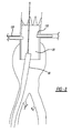
Figure 7 is a schematic view showing a pair of branch extension prostheses delivered to bridge the branches of the first endoluminal prosthesis with corresponding branch vessels and showing the dilator tip retracted and the delivery sheath disposed adjacent the distal end of the prosthesis; -
Figure 8 is a schematic view showing the delivery sheath disposed within the distal end of the first endoluminal prosthesis; -
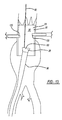
Figure 9 is a schematic view showing the peel-away sheath coupled to the delivery sheath for delivering the second endoluminal prosthesis from the peel-away sheath into the delivery sheath; -
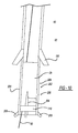
Figure 10 is a schematic view of the second endoluminal prosthesis within the peel-away sheath prior to insertion into the delivery sheath; -
Figure 11 is a schematic view showing the second endoluminal prosthesis partially inserted into the delivery sheath and the peel-away sheath partially peeled away; -
Figure 12 is a schematic view showing the second endoluminal prosthesis fully delivered into the delivery sheath and the peel-away sheath fully peeled away; -
Figure 13 is a schematic view showing the second endoluminal prosthesis partially exposed from the delivery sheath and within the distal end of the first endoluminal prosthesis; and -
Figure 14 is a schematic view showing the second endoluminal prosthesis fully exposed from the delivery sheath and mated with the first endoluminal prosthesis and the delivery sheath retracted distally from the prostheses. - The components in the Figures are not necessarily to scale, emphasis instead being placed upon illustrating the principles of the invention.
- In the present application, the term "proximal" refers to a direction that is generally closest to the heart during a medical procedure, while the term "distal" refers to a direction that is furthest from the heart during a medical procedure.
- Referring now to
Figures 1 to 14 , adelivery system 10 for facilitating deployment of afirst endoluminal prosthesis 20 and asecond endoluminal prosthesis 25 is provided. With reference toFigure 1 , thefirst endoluminal prosthesis 20 can comprise agraft 30 having a generally tubular body of a biocompatible material. Thegraft 30 has aproximal end 32, adistal end 34, and alumen 35 extending therebetween. Here, theprosthesis 20 is shown as thegraft 30, but the delivery system is not limited to this embodiment. - The
graft 30 can include a passageway orfenestration 38 disposed in thegraft 30 at a location between the proximal anddistal ends fenestration 38 can be one of many known passageway or fenestration types including, but not limited to, a pivoting fenestration, an internal branch, an external branch, an external helical branch, an internal/external branch, or other known passageways that provide fluid communication from inside thelumen 35 to outside of thegraft 30 so that blood flowing within thelumen 35 can pass to connected branch vessels within the body. For this discussion, the passageway orfenestration 38 will be described as an externalfirst branch 40 having proximal anddistal ends lumen 45 extending therebetween. Thefirst branch 40 may extend radially outward from thegraft 30, but may extend in a different direction in other embodiments. However, it will be appreciated that references to thefirst branch 40 can apply to other passageway or fenestration types. - Here, the
graft 30 is shown having the passageway orfenestration 38 in the form of thefirst branch 40. However, it will be appreciated that thesystem 10 is not limited to this embodiment. For example, theprosthesis 20 can be free of a passageway or fenestration in another embodiment. - In addition to the
first branch 40, thegraft 30 can include a second passageway orfenestration 48, described herein as asecond branch 50, having proximal anddistal regions lumen 55 extending therebetween. Thesecond branch 50 extends radially outward from thegraft 30, but may extend in a different direction. Again, it will be appreciated that the second passageway orfenestration 48 could be in another form, as described above with reference to the first passageway orfenestration 38. - In another embodiment, the
prosthesis 20, shown here as thegraft 30, can include a single passageway or fenestration. - It will be appreciated that additional passageways or fenestrations could also be included with the
graft 30, but for this discussion, thegraft 30 having the first andsecond branches - The
graft 30 is shown, in one form but not limited to this embodiment, as having a generally tubular shape with a generally constant diameter. It will be appreciated, however, that the outer profile, size, or shape of thegraft 30 can change depending on its particular application. For example, thegraft 30 could have a different diameter for different portions, or could be bifurcated with a pair of leg portions. However, for this discussion herein, thegraft 30 will be described as being tubular with a generally constant diameter. - With reference to
Figure 2 , thesecond endoluminal prosthesis 25, in one form but not limited to this embodiment, can be similar to thefirst prosthesis 20, where thesecond endoluminal prosthesis 25 may include agraft 60 having a generally tubular body of a biocompatible material. Thegraft 60 has aproximal end 62, adistal end 64, and a lumen 65 extending therebetween. Thegraft 60 may be in the form of a bifurcated graft where thedistal end 64 includes first andsecond leg portions lumen bifurcation region 72. In one form, thefirst leg portion 68 is longer than thesecond leg portion 70. For this discussion, thegraft 60 will be described as being bifurcated, but other shapes of thegraft 60 could also be used. - Many different types of graft materials may be used for the
grafts - The first and second
endoluminal prostheses grafts Figure 1 , astent 36 is coupled to an inner surface of thegraft 30 at a proximal region of thegraft 30, while a plurality ofstents 37 are coupled to an outer surface of thegraft 30 along a distal region of thegraft 30. Abare stent 39 can be coupled to the proximal end of thegraft 30 and used for anchoring theprosthesis 20 when it is expanded in a vessel. While one exemplary arrangement is shown inFigure 1 , it will be appreciated that thestents graft 30, and that the prosthesis can include various combinations and relative quantities of inner and outer stents. While theprostheses system 10 is not limited to these embodiments, and can be used to deliver prostheses without stents. - Similarly, in one embodiment as shown in
Figure 2 , astent 66 may be coupled to an inner surface of thegraft 60 at a proximal region of thegraft 60, while a plurality ofstents 67 are coupled to an outer surface of thegraft 60 along a distal region of thegraft 60. While one exemplary arrangement is shown inFigure 2 , it will be appreciated that thestents graft 30. Thegraft 60 can be provided without a bare stent, because thegraft 60 is intended to be inserted in an overlapping configuration within the distal end of thegraft 30, as further described below. - The
stents stents stents - In one example, shown in
Figures 1 and 2 , thestents stents bare stent 39 of theprosthesis 20 can be similarly constructed, and its distal end can be coupled to the proximal end of thegraft 30 such that thebare stent 39 will open outward at its proximal end to anchor theprosthesis 20. - The
graft 30 may have a compressed, reduced diameter delivery state, shown inFigure 3 , in which it may be advanced to a target location within a vessel, duct or other anatomical site, such as the abdominal aorta in the example ofFigures 5 to 14 below. Thegraft 30 further may have an expanded state, as shown inFigures 1 and6 to 9 ,13 , and14 , in which it may be configured to apply a radially outward force upon the vessel, duct or other target location. In the expanded state, fluid flow may be allowed through thelumen 35 of thegraft 30 and through thebranches - Similarly, the
graft 60 may have a compressed, reduced diameter delivery state, shown inFigure 4 in which it may be advanced to a target location within a vessel, duct or other anatomical site, such as the abdominal aorta in the example ofFigures 5-14 below. Thegraft 60 may also have an expanded state, as shown inFigures 2 and14 , in which it may be configured to apply a radially outward force upon the vessel, duct or other target location. In the expanded state, fluid flow can be allowed through the lumen 65 of thegraft 60. - One or more radiopaque markers may be provided to provide radiographic visualization of the position of the
endoluminal prosthesis 20 and/or 25 when placed in the vessel or duct of a patient. A plurality ofradiopaque markers 75, which according to one example may be provided in the form of gold beads, are coupled to thegrafts stents endoluminal prostheses - While the above described
prostheses grafts - With reference to
Figure 3 , theendoluminal prosthesis 20 may be provided as part of a preloaded system that can be guided along afirst guidewire 80 in a manner known in the art, which is configured to facilitate insertion of at least thefirst prosthesis 20 and preferably thesecond prosthesis 25, as well. More specifically, the delivery system of thefirst prosthesis 20 may include thefirst prosthesis 20 arranged in its compressed delivery configuration, and theguidewire 80 may extend through thelumen 35 along with adelivery catheter 86. Adilator tip 88 may be disposed at the proximal end of thecatheter 86 and proximally of thegraft 30. Thebare stent 39 may be compressed and may be held to thedilator tip 88. In one embodiment, thebare stent 39 may be held to thedilator tip 88 using one or more trigger wires (not shown) that can be withdrawn to release thebare stent 39. Of course, other manners of constraining thebare stent 39 can also be used and the system is not limited to the use of the described trigger wires. Adelivery sheath 90 may surround thegraft 30 and thecatheter 86 on which the graft is disposed. - With reference to
Figure 4 , theprosthesis 25 can also be preloaded into a delivery device, shown here as acartridge 200 but not limited to this embodiment. Thecartridge 200 can be in the form of a peel-awaysheath 202 having at least twoportions sheath 202 can further include scoring 208 extending longitudinally along the length of thesheath 202 to aid in peeling theportions graft 60 can be compressed in its preloaded state using known methods for constraining a self-expanding prosthesis. In one form, theproximal end 62 of thegraft 60 can be constrained in a tri-fold shape in a manner known in the art. In another form, theprosthesis 25 can be compressed radially with thegraft 60 material folded over itself in a manner known in the art. Theprosthesis 25 can be preloaded into thesheath 202 such that the graft material directly contacts the inner surface of thesheath 202 without an intermediate sheath between thegraft 60 and the peel-awaysheath 202. Theprosthesis 25 can be pre-loaded into the peel-awaysheath 202 without a traditional dilator tip, unlike theprosthesis 20 described above. By pre-loading theprosthesis 25 without an intermediate sheath the system can have a reduced diameter. By not having a traditional dilator tip, theprosthesis 25, when delivered toward theprosthesis 20, will prevent or otherwise limit crushing or otherwise damaging portions of theprosthesis 20 that has been previously delivered. - The peel-away
sheath 202 can include a pair oftab members 209 coupled to the distal ends ofportions portions sheath 202 can be free of tab members. - Referring now to
Figures 5 to 14 , exemplary method steps for using the prostheses ofFigures 1 to 4 to treat a condition in the area of a patient's abdominal aorta and/or branch vessels are shown and described. In a first step, theendoluminal prosthesis 20 is provided compressed into a delivery state, and is delivered into the patient's abdominal aorta using a suitable deployment system or introducer. An introducer such as that described inPCT application WO 98/53761 endoluminal prosthesis 20.PCT application WO 98/53761 - With reference to the system described above, the
prosthesis 20 is introduced into the patient's body percutaneously via femoral cut-down. Theguidewire 80 is introduced into the patient's body vessel and advanced toward the abdominal aorta and past the target location of theprosthesis 20. Thedelivery sheath 90, having theprosthesis 20,catheter 86, anddilator tip 88 is guided over theguidewire 80 and toward the target site, as shown inFigure 5 . To deploy theprosthesis 20, the operator can slide or retract thesheath 90 from thedelivery catheter 86 anddilator tip 88, thereby exposing theprosthesis 20. Theprosthesis 20 can be self-expanding and can expand outwardly upon removal of thesheath 90. Thebare stent 39 can be released by manipulating the trigger wires or other known restraining mechanism, allowing thebare stent 39 to expand outwardly into engagement with the body vessel to anchor theprosthesis 20, shown delivered inFigure 6 . The operator can directly manipulate thesheath 90 and thedelivery catheter 86, which provides the operator with a relatively high degree of control during the procedure. Further, such delivery devices may be compact and may have a relatively uniform, low-diameter radial profile, allowing for atraumatic access and delivery. - The
endoluminal prosthesis 20 is positioned within the abdominal aorta in the compressed state, for example, using theradiopaque markers 75, such that thebranches sheath 90 of the delivery system that constrains theendoluminal prosthesis 20 may be retracted distally to allow thestents graft 30 coupled thereto, to attain the expanded deployed configuration shown inFigure 6 . - In use, the
graft 30 is sized and configured so that at least an outer surface of the proximal region of thegraft 30 securely engages an inner surface of the abdominal aorta to hold thegraft 30 in place relative to the vasculature. Thedilator tip 88 and thecatheter 86 can be retracted through thesheath 90 and out of the patient, leaving thesheath 90 and guidewire 80 in place. - After the
graft 30 is securely deployed within the patient's abdominal aorta, in a next step,branch extension prosthesis graft 30 to bridge between thebranches branch extensions prosthesis 20, through brachial artery access, or the like. Of course, it will be appreciated that this method is exemplary, and that if no branch prostheses are used that they would not be deployed. - Referring to
Figure 7 , upon deployment, thebranch extension prosthesis 120 and thefirst branch 40 of thegraft 30 are mated such that there is a suitable tromboning connection, preferably with a 1.5 to 2 cm overlap and a 1 mm or less difference in diameter at the interconnection. Optionally, the devices may be expanded for about 30 seconds using a suitably sized balloon dilation catheter. At this time, thebranch extension prosthesis 120 can provide patent fluid flow through thegraft 30 into the corresponding branch vessel. Thebranch extension prosthesis 130 can be deployed similarly. Thebranch extension prostheses lumen 35 of thegraft 30, as shown inFigure 7 . - The
branch extension prosthesis 120, as well as thebranch extension prosthesis 130, may comprise a suitable graft or stent-graft known in the art to direct flow from thegraft 30 into the branch vessels. Of course, other types of branch extension prostheses and manners of deploying and coupling said branch extension prostheses could also be used with theprosthesis 20. - Having deployed the
prosthesis 20 andbranch extensions sheath 90 can remain in place near the distal end of thegraft 30. Thesheath 90, after being retracted to allow thegraft 30 to expand, can be held distally of the distal end of thegraft 30 prior to introduction of thebranch extensions sheath 90 can be advanced proximally back over theguidewire 80 and partially into the distal end of thegraft 30 prior to introduction of thebranch extensions - If the
sheath 90 is located distally of thegraft 30, thesheath 90 can be advanced back into thegraft 30, as shown inFigure 8 , so that it partially extends into the distal end of thegraft 30 after thebranch extensions sheath 90 can remain disposed distal of thegraft 30, if desired. - With the
proximal prosthesis 20 andbranch extensions distal prosthesis 25 is delivered. Theguidewire 80 andsheath 90 can remain in place after delivery of theprosthesis 20, as shown inFigure 9 . Thesheath 90 can include afunnel member 150 at the proximal end thereof to facilitate introduction of other components into thesheath 90. - With reference to
Figure 9 , to deliver theprosthesis 25 preloaded within the peel-awaysheath 202, thecartridge 200 can be delivered to thefunnel member 150 of thesheath 90. Thecartridge 200 can be placed over theguidewire 80 such that theguidewire 80 extends through the lumen 65 of thegraft 60 contained within thecartridge 200. The proximal end of the peel-awaysheath 202 is mated with thefunnel member 150 so that theprosthesis 25 can be transferred from the peel-awaysheath 202 into thesheath 90 that remained in place from the delivery of thefirst prosthesis 20. The peel-awaysheath 202 is preferably not inserted into thedelivery sheath 90, but rather will abut the distal end of thedelivery sheath 90 to allow thegraft 60 to be advanced from the peel-awaysheath 202 into thedelivery sheath 90. In this approach, the peel-awaysheath 202 will not overlap thedelivery sheath 90 while thegraft 60 is being advanced; however, thefunnel member 150 can overlap the proximal end of the peel-awaysheath 202 in this arrangement. It will be appreciated, however, that some overlap between the peel-awaysheath 202 and thedelivery sheath 90 can occur in other approaches without substantially deviating from the principles described herein. - The
cartridge 200 can include a pusher member 210 (Figure 4 ) positioned adjacent to theprosthesis 25 in a manner known in the art that has sufficient pushability to advance theprosthesis 25 through the peel-awaysheath 202 and, subsequently, thedelivery sheath 90. With reference toFigures 10-12 , after mating the peel-awaysheath 202 with thedelivery sheath 90, thegraft 60 can be advanced proximally from the peel-awaysheath 202 into thedelivery sheath 90 by advancing thepusher member 210. Thegraft 60 will preferably remain in its compressed delivery configuration substantially without expanding. The inner diameter of the peel-awaysheath 202 can correspond to the inner diameter of thedelivery sheath 90 to facilitate keeping thegraft 60 in its compressed configuration. However, it will be appreciated that some amount of expansion of the graft could also occur in the event that the inner diameter of thedelivery sheath 90 is larger than the inner diameter of the peel-awaysheath 202. This expansion can occur because thecartridge 200 does not include an intermediate sheath between thegraft 60 and the peel-awaysheath 202. - As the
graft 60 is advanced into thedelivery sheath 90, the portion of the peel-awaysheath 202 that is no longer covering thegraft 60 can be peeled away, as shown inFigure 11 . By peeling away thesheath 202, the user can maintain optimal control over thepusher member 210 near the distal end of thegraft 60 to facilitate advancement of thegraft 60 through the peel-awaysheath 202 and into thedelivery sheath 90. As thegraft 60 is further advanced, the peel-awaysheath 202 can be further peeled back. - Once the
graft 60 has been generally fully inserted into thedelivery sheath 90, as shown inFigure 12 , and the peel-awaysheath 202 has been fully peeled away, theportions sheath 202 can be discarded. Thegraft 60 can be further advanced through thedelivery sheath 90 using thepusher member 210. Thegraft 60 will advanced through thesheath 90 making direct contact with thedelivery sheath 90 as it is advanced. - With reference to
Figure 13 , thegraft 60 can be advanced through thesheath 90 and out of thesheath 90 at the distal end of thefirst graft 30, which has been previously deployed in the body vessel. The proximal end of thegraft 60 can be exposed from thedelivery sheath 90 and overlap the distal end of thegraft 30. Thedelivery sheath 90 is preferably disposed within thelumen 35 of thegraft 30 to facilitate delivering the proximal end of thegraft 60 within thelumen 35 of thegraft 30. - With reference to
Figure 14 , when thegraft 60 becomes exposed from thesheath 90, thegraft 60 can expand into engagement with thegraft 30 to create an overlapping connection. Thegraft 60 can be preferably self-expanding to facilitate this engagement. Thedelivery sheath 90 can then be withdrawn to expose the remainder of thegraft 60 in a manner known in the art. As thesheath 90 is withdrawn, thegraft 60 will expand where it has been exposed. The distal end of thegraft 60 is preferably aligned within a non-diseased portion of the body vessel, so that the distal end of thegraft 60 will expand into sealing engagement with the body vessel to allow blood to flow through thegrafts graft 60 can be disposed within a diseased body vessel, and an additional prosthesis can be delivered into engagement with the distal end of thegraft 60 to complete the bridge between non-diseased body vessel regions. - As described above, the
graft 60 can be a bifurcated graft in some embodiments, and thelonger leg portion 68 can be disposed within one of the iliac arteries, with theshorter leg portion 70 disposed near the other iliac artery. In another form, thegraft 60 can be bifurcated and include a pair of leg portions, each of which terminate prior to the iliac arteries. It will be appreciated that various shapes and types of prostheses can be delivered in thecartridge 200, and additional modular prostheses may be coupled to thegraft 60, e.g., extending into the iliac arteries, whereby the modular prostheses have outer surfaces dimensioned to securely engage inner surfaces of the iliac arteries or other vasculature. - The above described delivery of the
graft 60 using thecartridge 200 and peel-awaysheath 202 is different from the delivery of thegraft 30 because delivery of thegraft 60 did not use an inner catheter or dilator tip, and thesheath 90 that housed thegraft 30 was not peeled away. The use of thecartridge 200 thereby allows for delivery of thegraft 60 into thegraft 30 while limiting the possibility of contacting thebranch extension prostheses prostheses - While various embodiments of the invention have been described, the invention is not to be restricted to the combinations of features shown in a single one of the embodiments. On the contrary, the features of one embodiment may be added to or replace the features of another embodiment.
- All optional and preferred features and modifications of the described embodiments and dependent claims are usable in all aspects of the invention taught herein. Furthermore, the individual features of the dependent claims, as well as all optional and preferred features and modifications of the described embodiments are combinable and interchangeable with one another.
- The disclosures in United States patent application number
13/837,051
Claims (15)
- A system (10) for facilitating deployment of an endoluminal prosthesis, the system comprising:a delivery sheath (90);a distal prosthesis (25) having a compressed delivery state and an expanded state and being loaded in its delivery state into a peel-away sheath (202) and being moveable proximally relative to the peel-away sheath;wherein the peel-away sheath is sized and configured to mate with the delivery sheath so that the prosthesis is moveable from within the peel-away sheath into the delivery sheath lumen while remaining in its delivery state.
- A system (10) as claimed in claim 1, wherein the peel-away sheath (202) has at least two separable portions.
- A system (10) as claimed in claim 1 or 2, wherein the inner diameter of the peel-away sheath (202) generally corresponds to the inner diameter of the delivery sheath (90).
- A system (10) as claimed in claim 1, 2 or 3, wherein the prosthesis (25) is not coupled to a catheter.
- A system (10) as claimed in any preceding claim, wherein the prosthesis (25) is not coupled to a dilator tip.
- A system (10) as claimed in any preceding claim, wherein the prosthesis contacts (25) an inner surface of the peel-away sheath (202) when the prosthesis is in its delivery state.
- A system (10) as claimed in any preceding claim, wherein the prosthesis (25) includes a pair of leg portions at the distal end thereof.
- A system (10) as claimed in claim 7, wherein one of the leg portions is longer than the other.
- A system (10) as claimed in any preceding claim, wherein the distal end of the delivery sheath (90) is coupled to a funnel member (150) sized to receive the peel-away sheath (202) when the prosthesis (25) is in its delivery state.
- A system (10) as claimed in any preceding claim, wherein the peel-away sheath (202) includes scoring (208) extending longitudinally along its length.
- A system (10) as claimed in any preceding claim, including a pusher member (210) sized to be received within the peel-away sheath (202) and the delivery sheath (90), wherein the prosthesis (25) may be advanced by advancing the pusher member in contact with a distal end (64) of the prosthesis.
- A system (10) as claimed in any preceding claim, including a proximal prosthesis (20) having a compressed delivery state and an expanded state and being loaded in the delivery state within the delivery sheath (90) and moveable proximally relative to the delivery sheath.
- A system (10) as claimed in claim 12, wherein the proximal prosthesis (20) is coupled to a catheter (86) extending through a lumen of the proximal prosthesis and/or wherein the proximal prosthesis is coupled to a dilator tip (88) disposed proximally therefrom.
- A system (10) as claimed in claim 12 or 13, wherein the proximal prosthesis (20) includes a stent (39) coupled to the proximal end (32) of the graft (30) and being removably coupled to the dilator tip (88) when the proximal prosthesis is in its delivery state.
- A system (10) as claimed in any preceding claim including:means for delivering a proximal prosthesis (20) housed within the lumen of the delivery sheath (90) through a patient's skin and to a body vessel;means for exposing the proximal prosthesis from the proximal end of the delivery sheath at a target location within the body vessel;means for expanding the proximal prosthesis into engagement with a wall of the body vessel;means for delivering the distal prosthesis (25) to a distal opening of the delivery sheath, wherein the distal prosthesis is housed within the peel-away sheath (202), the peel-away sheath having at least two portions;means for advancing the distal prosthesis proximally relative to the peel-away sheath and into the distal opening of the delivery sheath;means for peeling away the at least two portions of the peel-away sheath while advancing the second endoluminal prosthesis;means for advancing the distal prosthesis proximally through the delivery sheath;means for exposing the second endoluminal prosthesis from a proximal end of the delivery sheath, preferably by retracting the delivery sheath; andmeans for expanding the second endoluminal prosthesis.
Applications Claiming Priority (1)
| Application Number | Priority Date | Filing Date | Title |
|---|---|---|---|
| US13/837,051 US9763816B2 (en) | 2013-03-15 | 2013-03-15 | Endoluminal prosthesis delivery system and method |
Publications (2)
| Publication Number | Publication Date |
|---|---|
| EP2799038A1 true EP2799038A1 (en) | 2014-11-05 |
| EP2799038B1 EP2799038B1 (en) | 2016-10-12 |
Family
ID=50942226
Family Applications (1)
| Application Number | Title | Priority Date | Filing Date |
|---|---|---|---|
| EP14275067.8A Active EP2799038B1 (en) | 2013-03-15 | 2014-03-14 | Endoluminal prosthesis delivery system |
Country Status (2)
| Country | Link |
|---|---|
| US (1) | US9763816B2 (en) |
| EP (1) | EP2799038B1 (en) |
Families Citing this family (5)
| Publication number | Priority date | Publication date | Assignee | Title |
|---|---|---|---|---|
| US10034784B2 (en) * | 2013-04-17 | 2018-07-31 | Gilbert H. L. Tang | Heart valve and endovascular graft components and method for delivery |
| NZ714341A (en) | 2013-05-03 | 2019-02-22 | Bard Inc C R | Peelable protective sheath |
| US11389627B1 (en) | 2018-10-02 | 2022-07-19 | Lutonix Inc. | Balloon protectors, balloon-catheter assemblies, and methods thereof |
| JP7609796B2 (en) | 2019-03-20 | 2025-01-07 | インキュベート メディカル テクノロジーズ、 エルエルシー | Aortic Dissection Implant |
| US11324583B1 (en) | 2021-07-06 | 2022-05-10 | Archo Medical LTDA | Multi-lumen stent-graft and related surgical methods |
Citations (4)
| Publication number | Priority date | Publication date | Assignee | Title |
|---|---|---|---|---|
| US5662675A (en) * | 1995-02-24 | 1997-09-02 | Intervascular, Inc. | Delivery catheter assembly |
| WO1998053761A1 (en) | 1997-05-26 | 1998-12-03 | William A. Cook Australia Pty. Ltd. | A prosthesis and a method and means of deploying a prosthesis |
| WO2000042948A2 (en) * | 1999-01-22 | 2000-07-27 | Gore Enterprise Holdings, Inc. | Low profile stent and graft combination |
| WO2012106491A1 (en) * | 2011-02-02 | 2012-08-09 | St. Jude Medical, Inc. | System and method for loading a collapsile heart valve into a delivery device |
Family Cites Families (13)
| Publication number | Priority date | Publication date | Assignee | Title |
|---|---|---|---|---|
| EP0539237A1 (en) | 1991-10-25 | 1993-04-28 | Cook Incorporated | Expandable transluminal graft prosthesis for repair of aneurysm and method for implanting |
| US6045557A (en) | 1995-11-10 | 2000-04-04 | Baxter International Inc. | Delivery catheter and method for positioning an intraluminal graft |
| WO1999062428A1 (en) | 1998-06-04 | 1999-12-09 | Scimed Life Systems, Inc. | Stent loading tool |
| US6261316B1 (en) | 1999-03-11 | 2001-07-17 | Endologix, Inc. | Single puncture bifurcation graft deployment system |
| ATE301426T1 (en) | 1999-10-08 | 2005-08-15 | Gen Hospital Corp | PERCUTANE STENT PROSTHESIS |
| KR20020082872A (en) | 2000-03-14 | 2002-10-31 | 쿡 인코포레이티드 | Edovascular stent graft |
| US20040138734A1 (en) | 2001-04-11 | 2004-07-15 | Trivascular, Inc. | Delivery system and method for bifurcated graft |
| US20080071343A1 (en) | 2006-09-15 | 2008-03-20 | Kevin John Mayberry | Multi-segmented graft deployment system |
| US20090093873A1 (en) | 2007-09-28 | 2009-04-09 | The Cleveland Clinic Foundation | Vascular graft and method of use |
| US8328861B2 (en) | 2007-11-16 | 2012-12-11 | Trivascular, Inc. | Delivery system and method for bifurcated graft |
| US8236040B2 (en) | 2008-04-11 | 2012-08-07 | Endologix, Inc. | Bifurcated graft deployment systems and methods |
| WO2010127040A1 (en) | 2009-04-28 | 2010-11-04 | Endologix, Inc. | Apparatus and method of placement of a graft or graft system |
| US8016872B2 (en) | 2009-12-22 | 2011-09-13 | Cook Medical Technologies Llc | Deployment and dilation with an expandable roll sock delivery system |
-
2013
- 2013-03-15 US US13/837,051 patent/US9763816B2/en active Active
-
2014
- 2014-03-14 EP EP14275067.8A patent/EP2799038B1/en active Active
Patent Citations (4)
| Publication number | Priority date | Publication date | Assignee | Title |
|---|---|---|---|---|
| US5662675A (en) * | 1995-02-24 | 1997-09-02 | Intervascular, Inc. | Delivery catheter assembly |
| WO1998053761A1 (en) | 1997-05-26 | 1998-12-03 | William A. Cook Australia Pty. Ltd. | A prosthesis and a method and means of deploying a prosthesis |
| WO2000042948A2 (en) * | 1999-01-22 | 2000-07-27 | Gore Enterprise Holdings, Inc. | Low profile stent and graft combination |
| WO2012106491A1 (en) * | 2011-02-02 | 2012-08-09 | St. Jude Medical, Inc. | System and method for loading a collapsile heart valve into a delivery device |
Also Published As
| Publication number | Publication date |
|---|---|
| EP2799038B1 (en) | 2016-10-12 |
| US9763816B2 (en) | 2017-09-19 |
| US20140277362A1 (en) | 2014-09-18 |
Similar Documents
| Publication | Publication Date | Title |
|---|---|---|
| US11547584B2 (en) | Delivery system and method to radially constrict a stent graft | |
| US10524908B2 (en) | Controlled tip release stent graft delivery system and method | |
| US10517748B2 (en) | Prosthesis with guide lumen | |
| US9993330B2 (en) | Endoluminal prosthesis system | |
| EP3210568B1 (en) | Endovascular stent graft assembly | |
| EP1492473B1 (en) | System for deploying multi-part endoluminal devices | |
| US20080228255A1 (en) | Positionable Stent-Graft Delivery System and Method | |
| US20100268318A1 (en) | Prosthesis for Antegrade Deployment | |
| EP2749253B1 (en) | Endoluminal prosthesis having modular branches | |
| EP2362760B1 (en) | Introducer for deploying a stent graft in a curved lumen | |
| JP6282898B2 (en) | Endovascular graft for treating iliac arteries and method for delivery and deployment of endovascular graft | |
| EP2702960B1 (en) | Endoluminal prosthesis and delivery device | |
| EP2799038B1 (en) | Endoluminal prosthesis delivery system |
Legal Events
| Date | Code | Title | Description |
|---|---|---|---|
| PUAI | Public reference made under article 153(3) epc to a published international application that has entered the european phase |
Free format text: ORIGINAL CODE: 0009012 |
|
| 17P | Request for examination filed |
Effective date: 20140314 |
|
| AK | Designated contracting states |
Kind code of ref document: A1 Designated state(s): AL AT BE BG CH CY CZ DE DK EE ES FI FR GB GR HR HU IE IS IT LI LT LU LV MC MK MT NL NO PL PT RO RS SE SI SK SM TR |
|
| AX | Request for extension of the european patent |
Extension state: BA ME |
|
| R17P | Request for examination filed (corrected) |
Effective date: 20150423 |
|
| RBV | Designated contracting states (corrected) |
Designated state(s): AL AT BE BG CH CY CZ DE DK EE ES FI FR GB GR HR HU IE IS IT LI LT LU LV MC MK MT NL NO PL PT RO RS SE SI SK SM TR |
|
| RIC1 | Information provided on ipc code assigned before grant |
Ipc: A61F 2/966 20130101AFI20160316BHEP Ipc: A61F 2/97 20130101ALI20160316BHEP |
|
| GRAP | Despatch of communication of intention to grant a patent |
Free format text: ORIGINAL CODE: EPIDOSNIGR1 |
|
| INTG | Intention to grant announced |
Effective date: 20160428 |
|
| GRAS | Grant fee paid |
Free format text: ORIGINAL CODE: EPIDOSNIGR3 |
|
| GRAA | (expected) grant |
Free format text: ORIGINAL CODE: 0009210 |
|
| AK | Designated contracting states |
Kind code of ref document: B1 Designated state(s): AL AT BE BG CH CY CZ DE DK EE ES FI FR GB GR HR HU IE IS IT LI LT LU LV MC MK MT NL NO PL PT RO RS SE SI SK SM TR |
|
| REG | Reference to a national code |
Ref country code: GB Ref legal event code: FG4D |
|
| REG | Reference to a national code |
Ref country code: CH Ref legal event code: EP |
|
| REG | Reference to a national code |
Ref country code: AT Ref legal event code: REF Ref document number: 835780 Country of ref document: AT Kind code of ref document: T Effective date: 20161015 |
|
| REG | Reference to a national code |
Ref country code: IE Ref legal event code: FG4D |
|
| REG | Reference to a national code |
Ref country code: DE Ref legal event code: R096 Ref document number: 602014004222 Country of ref document: DE |
|
| REG | Reference to a national code |
Ref country code: LT Ref legal event code: MG4D |
|
| REG | Reference to a national code |
Ref country code: NL Ref legal event code: MP Effective date: 20161012 |
|
| PG25 | Lapsed in a contracting state [announced via postgrant information from national office to epo] |
Ref country code: LV Free format text: LAPSE BECAUSE OF FAILURE TO SUBMIT A TRANSLATION OF THE DESCRIPTION OR TO PAY THE FEE WITHIN THE PRESCRIBED TIME-LIMIT Effective date: 20161012 |
|
| REG | Reference to a national code |
Ref country code: AT Ref legal event code: MK05 Ref document number: 835780 Country of ref document: AT Kind code of ref document: T Effective date: 20161012 |
|
| PG25 | Lapsed in a contracting state [announced via postgrant information from national office to epo] |
Ref country code: GR Free format text: LAPSE BECAUSE OF FAILURE TO SUBMIT A TRANSLATION OF THE DESCRIPTION OR TO PAY THE FEE WITHIN THE PRESCRIBED TIME-LIMIT Effective date: 20170113 Ref country code: SE Free format text: LAPSE BECAUSE OF FAILURE TO SUBMIT A TRANSLATION OF THE DESCRIPTION OR TO PAY THE FEE WITHIN THE PRESCRIBED TIME-LIMIT Effective date: 20161012 Ref country code: LT Free format text: LAPSE BECAUSE OF FAILURE TO SUBMIT A TRANSLATION OF THE DESCRIPTION OR TO PAY THE FEE WITHIN THE PRESCRIBED TIME-LIMIT Effective date: 20161012 Ref country code: NO Free format text: LAPSE BECAUSE OF FAILURE TO SUBMIT A TRANSLATION OF THE DESCRIPTION OR TO PAY THE FEE WITHIN THE PRESCRIBED TIME-LIMIT Effective date: 20170112 |
|
| PG25 | Lapsed in a contracting state [announced via postgrant information from national office to epo] |
Ref country code: FI Free format text: LAPSE BECAUSE OF FAILURE TO SUBMIT A TRANSLATION OF THE DESCRIPTION OR TO PAY THE FEE WITHIN THE PRESCRIBED TIME-LIMIT Effective date: 20161012 Ref country code: PT Free format text: LAPSE BECAUSE OF FAILURE TO SUBMIT A TRANSLATION OF THE DESCRIPTION OR TO PAY THE FEE WITHIN THE PRESCRIBED TIME-LIMIT Effective date: 20170213 Ref country code: BE Free format text: LAPSE BECAUSE OF FAILURE TO SUBMIT A TRANSLATION OF THE DESCRIPTION OR TO PAY THE FEE WITHIN THE PRESCRIBED TIME-LIMIT Effective date: 20161012 Ref country code: IS Free format text: LAPSE BECAUSE OF FAILURE TO SUBMIT A TRANSLATION OF THE DESCRIPTION OR TO PAY THE FEE WITHIN THE PRESCRIBED TIME-LIMIT Effective date: 20170212 Ref country code: ES Free format text: LAPSE BECAUSE OF FAILURE TO SUBMIT A TRANSLATION OF THE DESCRIPTION OR TO PAY THE FEE WITHIN THE PRESCRIBED TIME-LIMIT Effective date: 20161012 Ref country code: NL Free format text: LAPSE BECAUSE OF FAILURE TO SUBMIT A TRANSLATION OF THE DESCRIPTION OR TO PAY THE FEE WITHIN THE PRESCRIBED TIME-LIMIT Effective date: 20161012 Ref country code: PL Free format text: LAPSE BECAUSE OF FAILURE TO SUBMIT A TRANSLATION OF THE DESCRIPTION OR TO PAY THE FEE WITHIN THE PRESCRIBED TIME-LIMIT Effective date: 20161012 Ref country code: HR Free format text: LAPSE BECAUSE OF FAILURE TO SUBMIT A TRANSLATION OF THE DESCRIPTION OR TO PAY THE FEE WITHIN THE PRESCRIBED TIME-LIMIT Effective date: 20161012 Ref country code: AT Free format text: LAPSE BECAUSE OF FAILURE TO SUBMIT A TRANSLATION OF THE DESCRIPTION OR TO PAY THE FEE WITHIN THE PRESCRIBED TIME-LIMIT Effective date: 20161012 Ref country code: RS Free format text: LAPSE BECAUSE OF FAILURE TO SUBMIT A TRANSLATION OF THE DESCRIPTION OR TO PAY THE FEE WITHIN THE PRESCRIBED TIME-LIMIT Effective date: 20161012 |
|
| REG | Reference to a national code |
Ref country code: DE Ref legal event code: R097 Ref document number: 602014004222 Country of ref document: DE |
|
| PG25 | Lapsed in a contracting state [announced via postgrant information from national office to epo] |
Ref country code: RO Free format text: LAPSE BECAUSE OF FAILURE TO SUBMIT A TRANSLATION OF THE DESCRIPTION OR TO PAY THE FEE WITHIN THE PRESCRIBED TIME-LIMIT Effective date: 20161012 Ref country code: EE Free format text: LAPSE BECAUSE OF FAILURE TO SUBMIT A TRANSLATION OF THE DESCRIPTION OR TO PAY THE FEE WITHIN THE PRESCRIBED TIME-LIMIT Effective date: 20161012 Ref country code: SK Free format text: LAPSE BECAUSE OF FAILURE TO SUBMIT A TRANSLATION OF THE DESCRIPTION OR TO PAY THE FEE WITHIN THE PRESCRIBED TIME-LIMIT Effective date: 20161012 Ref country code: CZ Free format text: LAPSE BECAUSE OF FAILURE TO SUBMIT A TRANSLATION OF THE DESCRIPTION OR TO PAY THE FEE WITHIN THE PRESCRIBED TIME-LIMIT Effective date: 20161012 Ref country code: DK Free format text: LAPSE BECAUSE OF FAILURE TO SUBMIT A TRANSLATION OF THE DESCRIPTION OR TO PAY THE FEE WITHIN THE PRESCRIBED TIME-LIMIT Effective date: 20161012 |
|
| PLBE | No opposition filed within time limit |
Free format text: ORIGINAL CODE: 0009261 |
|
| STAA | Information on the status of an ep patent application or granted ep patent |
Free format text: STATUS: NO OPPOSITION FILED WITHIN TIME LIMIT |
|
| PG25 | Lapsed in a contracting state [announced via postgrant information from national office to epo] |
Ref country code: BG Free format text: LAPSE BECAUSE OF FAILURE TO SUBMIT A TRANSLATION OF THE DESCRIPTION OR TO PAY THE FEE WITHIN THE PRESCRIBED TIME-LIMIT Effective date: 20170112 Ref country code: IT Free format text: LAPSE BECAUSE OF FAILURE TO SUBMIT A TRANSLATION OF THE DESCRIPTION OR TO PAY THE FEE WITHIN THE PRESCRIBED TIME-LIMIT Effective date: 20161012 Ref country code: SM Free format text: LAPSE BECAUSE OF FAILURE TO SUBMIT A TRANSLATION OF THE DESCRIPTION OR TO PAY THE FEE WITHIN THE PRESCRIBED TIME-LIMIT Effective date: 20161012 |
|
| 26N | No opposition filed |
Effective date: 20170713 |
|
| REG | Reference to a national code |
Ref country code: CH Ref legal event code: PL |
|
| PG25 | Lapsed in a contracting state [announced via postgrant information from national office to epo] |
Ref country code: MC Free format text: LAPSE BECAUSE OF FAILURE TO SUBMIT A TRANSLATION OF THE DESCRIPTION OR TO PAY THE FEE WITHIN THE PRESCRIBED TIME-LIMIT Effective date: 20161012 Ref country code: SI Free format text: LAPSE BECAUSE OF FAILURE TO SUBMIT A TRANSLATION OF THE DESCRIPTION OR TO PAY THE FEE WITHIN THE PRESCRIBED TIME-LIMIT Effective date: 20161012 |
|
| REG | Reference to a national code |
Ref country code: FR Ref legal event code: ST Effective date: 20171130 |
|
| PG25 | Lapsed in a contracting state [announced via postgrant information from national office to epo] |
Ref country code: LU Free format text: LAPSE BECAUSE OF NON-PAYMENT OF DUE FEES Effective date: 20170314 Ref country code: FR Free format text: LAPSE BECAUSE OF NON-PAYMENT OF DUE FEES Effective date: 20170331 |
|
| PG25 | Lapsed in a contracting state [announced via postgrant information from national office to epo] |
Ref country code: LI Free format text: LAPSE BECAUSE OF NON-PAYMENT OF DUE FEES Effective date: 20170331 Ref country code: CH Free format text: LAPSE BECAUSE OF NON-PAYMENT OF DUE FEES Effective date: 20170331 |
|
| PG25 | Lapsed in a contracting state [announced via postgrant information from national office to epo] |
Ref country code: MT Free format text: LAPSE BECAUSE OF NON-PAYMENT OF DUE FEES Effective date: 20170314 |
|
| PG25 | Lapsed in a contracting state [announced via postgrant information from national office to epo] |
Ref country code: HU Free format text: LAPSE BECAUSE OF FAILURE TO SUBMIT A TRANSLATION OF THE DESCRIPTION OR TO PAY THE FEE WITHIN THE PRESCRIBED TIME-LIMIT; INVALID AB INITIO Effective date: 20140314 |
|
| PG25 | Lapsed in a contracting state [announced via postgrant information from national office to epo] |
Ref country code: CY Free format text: LAPSE BECAUSE OF FAILURE TO SUBMIT A TRANSLATION OF THE DESCRIPTION OR TO PAY THE FEE WITHIN THE PRESCRIBED TIME-LIMIT Effective date: 20161012 |
|
| PG25 | Lapsed in a contracting state [announced via postgrant information from national office to epo] |
Ref country code: MK Free format text: LAPSE BECAUSE OF FAILURE TO SUBMIT A TRANSLATION OF THE DESCRIPTION OR TO PAY THE FEE WITHIN THE PRESCRIBED TIME-LIMIT Effective date: 20161012 |
|
| PG25 | Lapsed in a contracting state [announced via postgrant information from national office to epo] |
Ref country code: TR Free format text: LAPSE BECAUSE OF FAILURE TO SUBMIT A TRANSLATION OF THE DESCRIPTION OR TO PAY THE FEE WITHIN THE PRESCRIBED TIME-LIMIT Effective date: 20161012 |
|
| PG25 | Lapsed in a contracting state [announced via postgrant information from national office to epo] |
Ref country code: AL Free format text: LAPSE BECAUSE OF FAILURE TO SUBMIT A TRANSLATION OF THE DESCRIPTION OR TO PAY THE FEE WITHIN THE PRESCRIBED TIME-LIMIT Effective date: 20161012 |
|
| P01 | Opt-out of the competence of the unified patent court (upc) registered |
Effective date: 20230602 |
|
| PGFP | Annual fee paid to national office [announced via postgrant information from national office to epo] |
Ref country code: GB Payment date: 20260319 Year of fee payment: 13 |
|
| PGFP | Annual fee paid to national office [announced via postgrant information from national office to epo] |
Ref country code: IE Payment date: 20260318 Year of fee payment: 13 Ref country code: DE Payment date: 20260320 Year of fee payment: 13 |