EP2798941A1 - Reel for a harvesting header - Google Patents
Reel for a harvesting header Download PDFInfo
- Publication number
- EP2798941A1 EP2798941A1 EP14165616.5A EP14165616A EP2798941A1 EP 2798941 A1 EP2798941 A1 EP 2798941A1 EP 14165616 A EP14165616 A EP 14165616A EP 2798941 A1 EP2798941 A1 EP 2798941A1
- Authority
- EP
- European Patent Office
- Prior art keywords
- bat
- bearing surface
- reel
- central tube
- mount
- Prior art date
- Legal status (The legal status is an assumption and is not a legal conclusion. Google has not performed a legal analysis and makes no representation as to the accuracy of the status listed.)
- Granted
Links
Images


Classifications
-
- A—HUMAN NECESSITIES
- A01—AGRICULTURE; FORESTRY; ANIMAL HUSBANDRY; HUNTING; TRAPPING; FISHING
- A01D—HARVESTING; MOWING
- A01D41/00—Combines, i.e. harvesters or mowers combined with threshing devices
- A01D41/12—Details of combines
- A01D41/14—Mowing tables
-
- A—HUMAN NECESSITIES
- A01—AGRICULTURE; FORESTRY; ANIMAL HUSBANDRY; HUNTING; TRAPPING; FISHING
- A01D—HARVESTING; MOWING
- A01D57/00—Delivering mechanisms for harvesters or mowers
- A01D57/01—Devices for leading crops to the mowing apparatus
- A01D57/02—Devices for leading crops to the mowing apparatus using reels
Definitions
- This invention relates to agricultural harvesters.
- it relates to agricultural harvesting heads for agricultural harvesters. More particularly, it relates to reels for agricultural harvesting heads.
- Agricultural harvesters such as combine harvesters travel through agricultural fields harvesting crops.
- the harvesting machines typically have an agricultural harvesting head disposed at the front of the agricultural harvester that engages the standing crop plants.
- the agricultural harvesting head functions by severing the stalks of the crop plants adjacent to their roots, and carrying the cut crop plants into the agricultural harvester for further processing.
- This function is provided by a reel.
- the reel extends laterally with respect to the direction of travel of the agricultural harvester.
- the reel engages the top portions of the crop plants as their stalks are severed, and pushes the upper portions of the crop plants rearward such that the cut crop plants are received by conveying mechanism on the agricultural harvesting head.
- the conveying mechanism carries the cut crop plants to the agricultural harvester where the crop plants are processed further.
- the reel of an agricultural harvesting head is generally in the form of central tube that extends laterally and is elongate.
- Several smaller tubes commonly called “bats” are distributed equiangularly around the circumference of the central tube. These bats are generally spaced equidistant from the central tube.
- Each bat supports several fingers that are spaced equidistantly apart with respect to each other. These fingers extend in the same direction on each bat.
- the central tube is driven in rotation, and in turn causes the bats to rotate about the longitudinal axis of the central tube. As each bat this sends and engages the tops of the uncut crop plants, the fingers on the bat urge the crop plants rearward and onto the upper surface of the agricultural harvesting head.
- This additional weight requires that the agricultural harvester be made heavier to support this weight, in particular the feederhouse upon which the agricultural harvesting head rests, and the hydraulic cylinders that raise and lower the feederhouse, and thus the agricultural harvesting head.
- a reel for an agricultural harvesting head comprises a central tube having a longitudinal rotational axis.
- a plurality of bat supports are fixed to and extend radially outward from the central tube.
- Each of the bat supports has an outer end to which a bat mount is fixed.
- a bat is supported for rotation within each of the bat supports.
- a thrust bearing is provided at each bat mount to communicate an axial load from the bat mount to the bat passing through the bat mount.
- a reel for an agricultural harvesting head comprising: a central tube that is elongate, that has a circumference, and that has a rotational axis; a plurality of bat supports mounted to the central tube and extending outward therefrom, wherein the bat supports are spaced longitudinally along the length of central tube; a plurality of bats that are elongate and extend parallel to the central tube, wherein the bats are spaced apart about the circumference and further wherein each of the bats is configured to support a plurality of spaced-apart fingers that are configured to engage the tops of crop plants and move them toward the agricultural harvesting head; a plurality of bat mounts fixed to outer ends of the bat supports, wherein each of the bat mounts defines an aperture in which as corresponding bat is supported; wherein the bat mounts and the bats are configured as thrust bearings to communicate an axial load in the bats to the ends of the bat supports to hold the bats in a predetermined position with respect
- Each bat mount of the plurality of bat mounts may have a first bearing surface disposed on a first side of the bat support and each bat of the plurality of bats may have a second bearing surface, and the first bearing surface and the second bearing surface may be facing surfaces and may be disposed to abut each other to form a first thrust bearing of the thrust bearings.
- the first bearing surface and the second bearing surface may be generally planar and may be perpendicular to a rotational axis of the bat.
- Each bat mount may have a third bearing surface disposed on a second side of the bat mount that is opposite to the first side of the bat mount and each bat may have a fourth bearing surface, and the third bearing surface and the fourth bearing surface may face each other and maybe disposed to abut each other to form a second thrust bearing of the thrust bearings.
- the third bearing surface and the fourth bearing surface may be generally planar and may be perpendicular to the rotational axis of the bat.
- the second bearing surface may be formed on an annular ring that is fixed to, surrounds, and extends radially outward from an outer surface of said each bat
- the fourth bearing surface may be formed on an annular ring that is fixed to, surrounds, and extends radially outward from the outer surface of said each bat.
- the first bearing surface may comprise a first bearing surface portion that is formed on a first hinged portion of said each bat mount, and the first bearing surface may comprise a second bearing surface portion that is formed on a second hinged portion of said each bat mount, and the first hinged portion and the second hinged portion may be hingeably coupled together.
- the first bearing surface portion and the second bearing surface portion may be coplanar and may together define an annular ring that surrounds an outer surface of each bat.
- the third bearing surface may comprise a third bearing surface portion that is formed on the first hinged portion of said each bat mount, and the third bearing surface may comprise a fourth bearing surface portion that is formed on the second hinged portion of said each bat mount.
- the first bearing surface and the second bearing surface of the first thrust bearing may be configured to withstand a single thrust load of 200 lbf without breaking.
- the first bearing surface and the second bearing surface of the first thrust bearing are configured to withstand a single thrust load of 400 lbf without breaking.
- the first bearing surface and the second bearing surface of the first thrust bearing may be configured to withstand a single thrust load of 800 lbf without breaking.
- the first bearing surface and the second bearing surface of the first thrust bearing may be configured to withstand 360,000 cycles of a 0 lbf to 100lbf to 0 lbf load without breaking.
- the first bearing surface and the second bearing surface of the first thrust bearing may be configured to withstand 360,000 cycles of a 0 lbf to 200lbf to 0 lbf load without breaking.
- a central tube length to central tube outer diameter ratio may be at least 45 and the reel may have a length of at least 20 feet long.
- a central tube length to central tube outer diameter ratio may be at least 50 and the reel may have a length of at least 25 feet long.
- a central tube length to central tube outer diameter ratio may be at least 55 and the reel may have a length of at least 30 feet long.
- an agricultural harvester 100 has a feederhouse 102 extending forward therefrom in a direction of travel "V".
- An agricultural harvesting head 104 is supported on the front end of the feederhouse 102.
- the agricultural harvesting head 104 comprises a reciprocating knife 106 which extends substantially the entire width of the agricultural harvesting head 104.
- a reel 108 is supported on the agricultural harvesting head 104 above the reciprocating knife 106 and extends substantially the entire width of the agricultural harvesting head 104.
- Opposing ends of the reel 108 are supported on arms 110 (only one is shown in Figure 1 ).
- the arms 110 have rear ends that are pivotally coupled to the frame 112 and extend forward therefrom.
- the frame extends laterally and substantially the entire width of the agricultural harvesting head 104.
- Each arm 110 has a hydraulic cylinder 114 associated there with that is disposed between and coupled to the arm 110 and the frame 112.
- the arms 110 (and therefore the reel 108) are raised and lowered by extending and retracting each hydraulic cylinder 114.
- Bats 116 (six in this example) are supported on a central tube 118.
- the central tube 118 forms the primary structural element of the reel 108.
- the central tube 118 is formed of steel or an aluminum alloy.
- the central tube may be circular in cross-section.
- the central tube may have flats defined up on its outer surface. These flats may extend in a direction parallel to the rotational axis 120.
- the central tube may have cutouts, slots, apertures, or other openings provided in the outer surface, for example, to reduce the weight of the central tube in areas in which the stress is not great.
- the central tube may be tapered over its length.
- the central tube may have struts or braces along its length to add additional strength.
- Each bat 116 is elongate and extends laterally. Each bat 116 is equiangularly spaced about the circumference of the central tube 118. Each bat 116 is spaced generally equidistantly from a rotational axis 120 of the central tube 118.
- Bats 116 may be made of an aluminum alloy or steel. Bats 116 may be tubular. Bats 116 may be solid in cross section. Bats 116 may be circular in cross-section. Bats 116 may have flutes, ridges, or flats formed on their outer surfaces.
- a plurality of fingers 122 are fixed to each bat 116.
- the plurality of fingers 122 on each bat 116 extend in the same general direction, such that as the bat approaches the crop plants, the fingers will simultaneously engage the tops of the crop plants.
- the fingers are unitary injection molded plastic structures. Alternatively, they may be made of an aluminum alloy or steel. The fingers may comprise springs to permit them to flex under load. The fingers may be comprised of a combination of disparate materials, such as combination of plastic, of steel, and of aluminum alloys.
- Each bat 116 is supported on the central tube 118 such that it can rotate about a longitudinal axis 124 as it simultaneously translates about the rotational axis 120.
- each finger is fixed to a bat at a corresponding finger mount 123.
- Finger mounts 123 are distributed equidistantly along substantially the entire length of each bat 116.
- Finger mounts 123 are generally formed is an aperture or depression formed in the outer surface of each bat 116. The finger mounts 123 serve to orient their corresponding fingers 122 such that all the fingers 122 on each bat 116 extend outwardly from the bat 116 in the same direction.
- reel 108 comprises the central tube 118, seven sets 126 of bat supports 128, seven bat support mounts 130, six bats 116 associated with each bat support mount 130, and bat mounts 132 fixed to the end of each bat support 128.
- the central tube has a left axle 134 and a right axle 136 that are fixed to the left end and the right end of the central tube 118 and extend outward therefrom.
- the reel 108 is supported on the left axle 134 and the right axle 136 for rotation about the rotational axis 120.
- this length refers to the distance between the two arms that support opposing ends of the reel. In most cases, this will be substantially the same length as the overall length of the bats 116 and the overall length of the central tube 118.
- Each bat support 128 is fixed at its inner end to the bat support mount 130 on the central tube 118 and extends outward therefrom.
- Each of the bat supports 128 in each set 126 of bat supports 128 is spaced equiangularly about the circumference of the central tube 118. In this example, since there are six bat supports 128 in each set 126 of bat supports 128, every bat support 128 is spaced 60° apart from its adjacent bat support.
- Each set 126 of bat supports 128 is spaced equidistant from its adjacent set 126 of bat supports 128 along the length of the central tube 118.
- a crank 138 is fixed to the left end of each bat 116.
- a crank 140 is fixed to the right end of each bat 116.
- the bats are rotated within bat mounts 132 through which they pass by pivoting the crank 138 and the crank 140 with respect to the bat mounts 132. This pivoting movement causes each of the bats 116 two simultaneously rotate with respect to all of the bat mounts 132 that support that bat 116 over its length. Since there are seven sets 126 of bat supports 128, each bat passes through and is supported for rotation by seven bat mounts 132.
- Each bat support 128 has an associated strut 142 that is fixed to the bat support 128 and that is also fixed to the central tube 118.
- the strut 142 extends generally in an axial direction. This arrangement stiffens the bat support 128 to which the strut 142 is attached thereby reducing the ability of the bat support to be flexed back and forth in an axial direction (i.e. in a direction generally parallel to the rotational axis 120) at the outer end of the bat support 128.
- Not every bat support 128 has an associated strut 142.
- the set of bat supports 128 located at the middle of the reel does not have any struts 142 associated therewith.
- each bat mount 132 is removably fixed to the outer end of its corresponding bat support 128 by removable fasteners 144.
- the removable fasteners 144 permit the bat mount 132 to be separated from both the bat 116 is supported within the bat mount 132 and from the outer end of the bat support 128.
- the removal fasteners 144 are threaded fasteners.
- the removable fasteners 144 comprise a nut and a bolt.
- Each strut 142 is fixed to its corresponding bat support 128, preferably permanently, and by welding the strut 142 to the bat support 128.
- Each strut 142 is removably fixed to the central tube 118 with removable fasteners 146.
- the removable fasteners 146 are threaded fasteners.
- the removable fasteners 146 comprise a nut and a bolt.
- the central tube 118 comprises a strut mount 148 associated with each strut 142.
- Each strut mount 148 is fixed to the central tube 118 and is configured to engage and be fixed to an associated strut 142.
- each strut mount 148 is welded to the central tube 118 and includes a flange 150 that extends radially outward from the rotational axis 120 of the central tube 118.
- Each set 126 of bat supports 128 are fixed to a bat mount 132 which is in the form of an annular ring.
- the bat mount 132 of each set 126 of bat supports 128 is fixed to the central tube 118.
- the bat mount 132 is welded to the central tube 118.
- the bat mount 132 is generally planar, and lies in a plane generally perpendicular to the rotational axis 120.
- Bat supports 128 are removably fixed to the bat mount 132 by removable fasteners 154. These removable fasteners 154 hold their associated bat supports 128 in their relative angular positions with respect to the central tube 118.
- Each bat support 128 is generally U-shaped. Each bat support 128 has a web 156 that is generally planar and extends in a plane perpendicular to the rotational axis 120. Each bat support has a front flange 158 that is fixed to a forward edge of the web 156 and extends radially and generally parallel to the rotational axis 120. Each bat support 128 has a rear flange 160 that is fixed to a rear edge of the web 156 and extends radially and generally parallel to the rotational axis 120. The web 156 of each bat support 128 is fastened to the bat mount 132.
- each bat support 128 is fixed to the web 156 of that bat support 128 between the inner end of the bat support 128 where the bat support 128 is fixed to the central tube, and the outer end of the bat support 128 where the bat mount 132 is located.
- each bat mount 132 is comprised of two hinged portions 162 that are hingeably coupled together with a hinge pin 164.
- Each hinge portion 162 comprises a hinge coupling 166 located at an outer end of the hinge portion 162.
- Each hinge portion 162 comprises a strap portion 168 coupled to the hinge coupling 166.
- the strap portion 168 defines a semicircular recess 170 configured to receive and support a portion of the circular outer surface 172 of the bat 116.
- Each hinge portion 162 comprises a mounting portion 174 that is coupled to the strap portion 168 on the opposite side of the strap portion 168 from the hinge portion 162. When the two hinged portions 162 are closed the strap portions 168 define a circular aperture 163 extending completely around the circular outer surface of the bat 116.
- the bat mounts 132 are comprised of a polymer.
- the polymer may comprise a fiber reinforced plastic.
- the polymer may comprise polyethylene.
- the polymer may comprise nylon.
- the bat mounts 132 are comprised of an aluminum alloy.
- the bat mounts 132 are comprised of steel.
- Each hinge portion 162 has a bearing surface 176 on a first side of the hinge portion 162 that is generally planar and perpendicular to the rotational axis 120.
- the bearing surface 176 faces in a direction generally parallel to the rotational axis 120 and toward one end of the central tube 118.
- the bearing surface 176 is also oriented generally parallel to the longitudinal axis 124 of the bat 116 upon which it is mounted.
- Each hinge portion 162 has a bearing surface 178 located on a second side of the hinge portion 162 (that is opposite to the first side of the hinge portion 162).
- the bearing surface 178 faces in a direction generally parallel to the rotational axis 120 and toward the longitudinal center of the central tube 118.
- the bearing surface 178 is also oriented generally parallel to the longitudinal axis 124 of the bat 116 upon which it is mounted.
- the bearing surface 176 is immediately adjacent to and engages a first corresponding bearing surface 180 that is provided on the bat 116.
- the bearing surface 178 is immediately adjacent to and engages a second bearing surface 182 that is provided on the bat 116.
- the first corresponding bearing surface 180 and the second corresponding bearing surface 182 are generally planar are and are oriented parallel to the rotational axis 120 and parallel to the longitudinal axis 124 of the bat on which they are provided.
- first corresponding bearing surface 180 and the second corresponding bearing surface 182 are provided on the two inner facing surfaces of a first annular ring 184, and a second annular ring 186, respectively.
- a slight clearance (1-4 mm) is provided between the annular rings and the bat mount to permit the bat 116 to rotate with respect to the bat mount.
- the bearing surface 176 and the first corresponding bearing surface 180 define a thrust bearing that prevents the bat mount 132 from translating along the bat 116 in one axial direction.
- the bearing surface 178 and the second corresponding bearing surface 182 define a thrust bearing that prevents the bat mount 132 from translating along the bat 116 in a second axial direction opposite the one axial direction.
- These two thrust bearings are defined by the abutting surfaces on the bat mount and the annular rings of the bat 116 are sized to communicate substantial thrust loads on the order of at least 100 pounds-force even as the bat 116 rotates within the bat mount.
- each bat mount 132 defines two thrust bearings, one on each side of the bat mount 132.
- each bat mount may define a single thrust bearing capable of communicating thrust from the bat 116 to the bat mount 132 in one direction but not in the other direction.
- a central tube 118 having a smaller diameter and a thinner wall can be provided that is relatively flexible. And that, but for the thrust bearings arrangement, might sag or droop in the middle by several millimeters. This sagging is at its greatest at the longitudinal midpoint of the central tube 118.
- the bat supports 128 extending downward from the bottom of the central tube 118 will spread apart, reaching their greatest spread at their outermost ends where the bat mounts 132 are located.
- the thrust bearings defined between the bats 116 and the bat mounts 132 exert an inward force on the bat mounts that tends to hold the ends of the bat mounts together.
- the thrust bearings communicate this force through the bat to adjacent bat mounts 132 by placing the bat 116 in tension.
- the thrust bearing arrangement described above permit some of the gravitational load on the reel 108 to be transmitted to the bats 116 via the thrust bearings that are defined between the bat mounts 132 and the bats 116. This in turn, permits the central tube 118 to be made smaller, lighter, and hence more flexible.
- the wall thickness of the central tube 118 can be reduced. Furthermore, the overall diameter of the central tube 118 can also be reduced. Reducing the wall thickness of the central tube 118 and the diameter of the central tube 118 permits the agricultural harvesting head 104 to be reduced in weight.
- the thrust loads countered by the thrust bearings must be sufficient to lift the central tube 118 and prevent it from drooping or sagging under the weight of gravity.
- thrust bearings may vary from that which is shown therein.
- the thrust bearings formed by the bat mounts 132 and the bats 116 are sized sufficient to resist a one-time tensile axial load of at least 200 lbf in the bat 116 applied to the bat mount 132 without breaking the bat 116 or the bat mount 132.
- the thrust bearings formed by the bat mounts 132 in the bats 116 are sized sufficient to resist a one-time tensile axial load of at least 400 lbf in the bat 116 applied to the bat mount 132 without breaking the bat 116 or the bat mount 132.
- the thrust bearings formed by the bat mounts 132 and the bats 116 are sized sufficient to resist a one-time tensile axial load of at least 800 lbf in the bat 116 applied to the bat mount 132 without breaking the bat 116 or the bat mount 132.
- the thrust bearings are also sized sufficient to permit continuous operation of the reel for 360,000 reel rotations (a typical year's operation) of the agricultural harvester with a cyclical load in which each reel rotation constitutes cycling the thrust bearing over an axial tensile load that starts at zero, then increases to 100 lbf in tension, then drops to zero, then increases to - 100 lbf (i.e. compression), then returns to zero lbf (which is defined as one full cycle at 100 lbf) without breaking the bat 116 or the bat mount 132.
- the thrust bearings are sized sufficient to permit the same continuous operation cycling from 0 lbf to 200 lbf to 0 lbf to -200 lbf to 0 lbf without breaking the bat 116 or the bat mount 132.
- the thrust bearings are sized sufficient to permit the same continuous operation, cycling instead from 0 lbf to 400 lbf to 0 lbf to -400 lbf to 0 lbf without breaking the bat 116 or the bat mount 132.
- the ratio of the central tube length divided by the central tube outer diameter i.e. the central-tube-length-to-central-tube-diameter
- Prior art central-tube-length-to-central-tube-diameter ratios vary from 30-40 for reels that are 20 feet long.
- Prior art central-tube-length-to-central-tube-diameter ratios vary from 35-45 for reels that are 30 feet long and 42-53 for reels that are 35 feet long.
- central-tube-length-to-central-tube-diameter ratio can be at least 45, alternatively at least 55. Alternatively they can be at least 65 for reels in the range of 20-25 feet long.
- central-tube-length-to-central-tube-diameter ratio can be at least 50, alternatively at least 60, and alternatively at least 70 for reels in the range of 25-30 feet long.
- central-tube-length-to-central-tube-diameter ratios can be at least 55 for reels in the range of 30-35 feet long. Alternatively they can be at least 65 for reels in the range of 30-35 feet long. Alternatively they can be at least 75 for reels in the range of 30-35 feet long.
- central-tube-length-to-central-tube-diameter ratios can be at least 60 for reels with a length greater than 35 feet.
- central-tube-length-to-central-tube-diameter ratios can be at least 72 for reels with a length greater than 35 feet.
- central-tube-length-to-central-tube-diameter ratios can be at least 85 for reels with a length greater than 35 feet.
- the thrust bearing arrangement described herein permits the use of a central tube having a smaller outer diameter relative to the length of the reel, additional strength can be provided for the reel by increasing the wall thickness of the central tube relative to the outer diameter of the central tube while still decreasing the total weight of the central tube 118 as compared to the prior art.
- Prior art central-tube-outer-diameter-to-wall-thickness ratios are typically 80-95 for reels with an overall length in the range of 20-25 feet.
- Prior art central-tube-outer-diameter-to-wall-thickness ratios range between 100-125 four reels with an overall length in the range of 30-35 feet.
- the central-tube-outer-diameter-to-wall-thickness ratio can be reduced to no greater than 75 four reels in the range of 20-25 feet long.
- the central-tube-outer-diameter-to-wall-thickness ratio can be reduced to no greater than 68 for reels in the range of 20-25 feet long.
- the central-tube-outer-diameter-to-wall-thickness ratio can be reduced to no greater than 63 for reels in the range of 20-25 feet long.
- the central-tube-outer-diameter-to-wall-thickness-ratio can be reduced to no greater than 80 for reels with a length in the range of 25-50 feet long.
- the central-tube-outer-diameter-to-wall-thickness-ratio can be reduced to no greater than 72 for reels with a length in the range of 25-50 feet long.
- the central-tube-outer-diameter-to-wall-thickness-ratio can be reduced to no greater than 65 for reels with a length in the range of 25-50 feet long.
- any increase in the diameter of the reel requires longer bat supports. This increases the weight of the reel. Consequently, the diameter of the central tube must be increased and the wall thickness increased to maintain the same rigidity of the reel. Both the greater length of the bat supports and the larger diameter and wall thickness of the real result in a significantly increased weight to the reel.
- the present thrust bearing arrangement increasing the length of the bat supports does not require a larger reel.
- increased length of the bat supports provide substantially more rigidity, since the rigidity provided by the thrust bearing arrangement is a function not only the tension in the bats, but also the length of the reels.
- the greater the length of the bat supports the greater the rigidity provided by the thrust bearing arrangement (for any given tension in the bats).
- the thrust bearing arrangement more than compensates this increased weight by the increased rigidity provided due to the greater length of the bat supports.
- the central tube does not have to be increased in diameter or wall thickness even when longer bat supports are provided as long as the thrust bearing arrangement described herein is provided to help support the reel and increases rigidity.
- This increased bat support length relative to the outer diameter of the central tube 118 can be expressed as a ratio of the outer diameter of the central tube 118 to the major diameter of the reel (central-tube-outer-diameter-to-major-diameter-of-the-reel).
- major diameter means the diameter of an imaginary circle that is small enough to just circumscribe the bats, wherein the imaginary circle is defined in a plane that is perpendicular to the rotational axis 120.
- the ratio of the central tube outer diameter (in millimeters) to the major diameter of the reel (in inches) was not less than 2.8.
- the ratio of the central-tube-outer-diameter-to-major-diameter-of-the-reel was no less than 4.9.
- the central-tube-outer-diameter-to-major-diameter-of-the-reel ratio is no greater than 2.7.
- the central-tube-outer-diameter-to-major-diameter-of-the-reel ratio is no greater than 2.5.
- the central-tube-outer-diameter-to-major-diameter-of-the-reel ratio is no greater than 2.0.
- the central-tube-outer-diameter-to-major-diameter-of-the-reel ratio is no greater than 4.0.
- the central-tube-outer-diameter-to-major-diameter-of-the-reel ratio is no greater than 3.5.
- the central-tube-outer-diameter-to-major-diameter-of-the-reel ratio is no greater than 3.0.
- first and second annular rings may be collars that are permanently fixed or removably fixed to the bat. They annular rings may be formed integral with the bat. The annular rings may extend into instead of out of the surface of the bar. The annular rings may be held in their longitudinal position on the bat by a key or other fixation means such as a bolt or screw.
- the bearing surfaces may be conical or curved.
- the annular rings may be fashioned in separate pieces that are assembled around the bat.
- the annular rings may be formed as part of a common member or members that are positioned on the bat and fixed in place.
- the bat supports can be made rigid and the struts dispensed with entirely. There may be more or less than six bats distributed around the central tube.
- Each bat and bat mount need not be configured as a thrust bearing.
- Some of the sets (126) of bat supports need not be configured to have thrust bearings.
- Other alterations and configurations of the reel may be provided that are consistent with the claims recited below. The full scope of the invention is recited in the claims below and is not limited by the specific embodiments disclosed herein.
Landscapes
- Life Sciences & Earth Sciences (AREA)
- Environmental Sciences (AREA)
- Harvester Elements (AREA)
- Storage Of Web-Like Or Filamentary Materials (AREA)
- Outside Dividers And Delivering Mechanisms For Harvesters (AREA)
Abstract
Description
- This invention relates to agricultural harvesters. In particular it relates to agricultural harvesting heads for agricultural harvesters. More particularly, it relates to reels for agricultural harvesting heads.
- Agricultural harvesters such as combine harvesters travel through agricultural fields harvesting crops. The harvesting machines typically have an agricultural harvesting head disposed at the front of the agricultural harvester that engages the standing crop plants.
- The agricultural harvesting head functions by severing the stalks of the crop plants adjacent to their roots, and carrying the cut crop plants into the agricultural harvester for further processing.
- There is a need to direct the crop plants onto the agricultural harvesting head as the roots are severed. This function is provided by a reel. The reel extends laterally with respect to the direction of travel of the agricultural harvester. The reel engages the top portions of the crop plants as their stalks are severed, and pushes the upper portions of the crop plants rearward such that the cut crop plants are received by conveying mechanism on the agricultural harvesting head. The conveying mechanism carries the cut crop plants to the agricultural harvester where the crop plants are processed further.
- The reel of an agricultural harvesting head is generally in the form of central tube that extends laterally and is elongate. Several smaller tubes commonly called "bats" are distributed equiangularly around the circumference of the central tube. These bats are generally spaced equidistant from the central tube. Each bat supports several fingers that are spaced equidistantly apart with respect to each other. These fingers extend in the same direction on each bat.
- The central tube is driven in rotation, and in turn causes the bats to rotate about the longitudinal axis of the central tube. As each bat this sends and engages the tops of the uncut crop plants, the fingers on the bat urge the crop plants rearward and onto the upper surface of the agricultural harvesting head.
- In recent years, agricultural harvesting heads have been made longer and longer. This increased length as required that the central tubes be made stiffer so they do not sag in the middle. When the central tube sags in the middle, there is a risk that the fingers will be cut by the elongate reciprocating knife that severs the stalks of the crop plants adjacent to the roots. This need for greater stiffness due to length is required that the central tube be made with a larger diameter, and often with a thicker wall as well. This, in turn, means that the agricultural harvesting head is not just heavier proportional to its length but heavier due to the increased wall thickness of the central tube and larger diameter of the central tube.
- This additional weight, in turn, requires that the agricultural harvester be made heavier to support this weight, in particular the feederhouse upon which the agricultural harvesting head rests, and the hydraulic cylinders that raise and lower the feederhouse, and thus the agricultural harvesting head.
- What is required, therefore, is a reel that is lighter in weight than the traditional reel arrangement. It is an object of this invention to provide such a reel.
- In accordance with one aspect of the invention, a reel for an agricultural harvesting head comprises a central tube having a longitudinal rotational axis. A plurality of bat supports are fixed to and extend radially outward from the central tube. Each of the bat supports has an outer end to which a bat mount is fixed. A bat is supported for rotation within each of the bat supports. A thrust bearing is provided at each bat mount to communicate an axial load from the bat mount to the bat passing through the bat mount.
- In accordance with another aspect of the invention, a reel for an agricultural harvesting head is provided, the reel comprising: a central tube that is elongate, that has a circumference, and that has a rotational axis; a plurality of bat supports mounted to the central tube and extending outward therefrom, wherein the bat supports are spaced longitudinally along the length of central tube; a plurality of bats that are elongate and extend parallel to the central tube, wherein the bats are spaced apart about the circumference and further wherein each of the bats is configured to support a plurality of spaced-apart fingers that are configured to engage the tops of crop plants and move them toward the agricultural harvesting head; a plurality of bat mounts fixed to outer ends of the bat supports, wherein each of the bat mounts defines an aperture in which as corresponding bat is supported; wherein the bat mounts and the bats are configured as thrust bearings to communicate an axial load in the bats to the ends of the bat supports to hold the bats in a predetermined position with respect to each other and wherein the bat supports are sufficiently rigid to communicate the forces applied to their ends to the central tube and reduce sagging of the central tube.
- Each bat mount of the plurality of bat mounts may have a first bearing surface disposed on a first side of the bat support and each bat of the plurality of bats may have a second bearing surface, and the first bearing surface and the second bearing surface may be facing surfaces and may be disposed to abut each other to form a first thrust bearing of the thrust bearings.
- The first bearing surface and the second bearing surface may be generally planar and may be perpendicular to a rotational axis of the bat.
- Each bat mount may have a third bearing surface disposed on a second side of the bat mount that is opposite to the first side of the bat mount and each bat may have a fourth bearing surface, and the third bearing surface and the fourth bearing surface may face each other and maybe disposed to abut each other to form a second thrust bearing of the thrust bearings.
- The third bearing surface and the fourth bearing surface may be generally planar and may be perpendicular to the rotational axis of the bat.
- The second bearing surface may be formed on an annular ring that is fixed to, surrounds, and extends radially outward from an outer surface of said each bat, and the fourth bearing surface may be formed on an annular ring that is fixed to, surrounds, and extends radially outward from the outer surface of said each bat.
- The first bearing surface may comprise a first bearing surface portion that is formed on a first hinged portion of said each bat mount, and the first bearing surface may comprise a second bearing surface portion that is formed on a second hinged portion of said each bat mount, and the first hinged portion and the second hinged portion may be hingeably coupled together.
- The first bearing surface portion and the second bearing surface portion may be coplanar and may together define an annular ring that surrounds an outer surface of each bat.
- The third bearing surface may comprise a third bearing surface portion that is formed on the first hinged portion of said each bat mount, and the third bearing surface may comprise a fourth bearing surface portion that is formed on the second hinged portion of said each bat mount.
- The first bearing surface and the second bearing surface of the first thrust bearing may be configured to withstand a single thrust load of 200 lbf without breaking.
- The first bearing surface and the second bearing surface of the first thrust bearing are configured to withstand a single thrust load of 400 lbf without breaking.
- The first bearing surface and the second bearing surface of the first thrust bearing may be configured to withstand a single thrust load of 800 lbf without breaking.
- The first bearing surface and the second bearing surface of the first thrust bearing may be configured to withstand 360,000 cycles of a 0 lbf to 100lbf to 0 lbf load without breaking.
- The first bearing surface and the second bearing surface of the first thrust bearing may be configured to withstand 360,000 cycles of a 0 lbf to 200lbf to 0 lbf load without breaking.
- A central tube length to central tube outer diameter ratio may be at least 45 and the reel may have a length of at least 20 feet long.
- A central tube length to central tube outer diameter ratio may be at least 50 and the reel may have a length of at least 25 feet long.
- A central tube length to central tube outer diameter ratio may be at least 55 and the reel may have a length of at least 30 feet long.
-
-
Figure 1 illustrates an agricultural harvester with a reel in accordance with the present invention. -
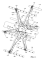
Figure 2 illustrates the reel of the agricultural harvester ofFigure 1 in perspective view with all the other components, including the reel fingers, removed. -
Figure 3 is a fragmentary perspective detail view of the left end of the reel shown inFigure 2 . -
Figure 4 is an enlarged fragmentary perspective detail view of a central portion of the reel shown inFigure 3 . -
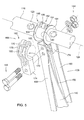
Figure 5 is a partially exploded view of the outer end of a reel support, a reel mount, and a bat shown inFigure 4 . - In
Figure 1 , anagricultural harvester 100 has afeederhouse 102 extending forward therefrom in a direction of travel "V". Anagricultural harvesting head 104 is supported on the front end of thefeederhouse 102. Theagricultural harvesting head 104 comprises a reciprocatingknife 106 which extends substantially the entire width of theagricultural harvesting head 104. Areel 108 is supported on theagricultural harvesting head 104 above the reciprocatingknife 106 and extends substantially the entire width of theagricultural harvesting head 104. - Opposing ends of the
reel 108 are supported on arms 110 (only one is shown inFigure 1 ). Thearms 110 have rear ends that are pivotally coupled to theframe 112 and extend forward therefrom. The frame extends laterally and substantially the entire width of theagricultural harvesting head 104. Eacharm 110 has ahydraulic cylinder 114 associated there with that is disposed between and coupled to thearm 110 and theframe 112. The arms 110 (and therefore the reel 108) are raised and lowered by extending and retracting eachhydraulic cylinder 114. Bats 116 (six in this example) are supported on acentral tube 118. Thecentral tube 118 forms the primary structural element of thereel 108. Thecentral tube 118 is formed of steel or an aluminum alloy. The central tube may be circular in cross-section. It may have flats defined up on its outer surface. These flats may extend in a direction parallel to therotational axis 120. The central tube may have cutouts, slots, apertures, or other openings provided in the outer surface, for example, to reduce the weight of the central tube in areas in which the stress is not great. The central tube may be tapered over its length. The central tube may have struts or braces along its length to add additional strength. - Each
bat 116 is elongate and extends laterally. Eachbat 116 is equiangularly spaced about the circumference of thecentral tube 118. Eachbat 116 is spaced generally equidistantly from arotational axis 120 of thecentral tube 118.Bats 116 may be made of an aluminum alloy or steel.Bats 116 may be tubular.Bats 116 may be solid in cross section.Bats 116 may be circular in cross-section.Bats 116 may have flutes, ridges, or flats formed on their outer surfaces. - A plurality of
fingers 122 are fixed to eachbat 116. The plurality offingers 122 on eachbat 116 extend in the same general direction, such that as the bat approaches the crop plants, the fingers will simultaneously engage the tops of the crop plants. - The fingers are unitary injection molded plastic structures. Alternatively, they may be made of an aluminum alloy or steel. The fingers may comprise springs to permit them to flex under load. The fingers may be comprised of a combination of disparate materials, such as combination of plastic, of steel, and of aluminum alloys.
- Each
bat 116 is supported on thecentral tube 118 such that it can rotate about alongitudinal axis 124 as it simultaneously translates about therotational axis 120. - In
Figures 2-5 , all of thefingers 122 have been removed for convenience of illustration. Each finger is fixed to a bat at acorresponding finger mount 123. Finger mounts 123 are distributed equidistantly along substantially the entire length of eachbat 116. Finger mounts 123 are generally formed is an aperture or depression formed in the outer surface of eachbat 116. The finger mounts 123 serve to orient theircorresponding fingers 122 such that all thefingers 122 on eachbat 116 extend outwardly from thebat 116 in the same direction. - In
Figure 2 , reel 108 comprises thecentral tube 118, sevensets 126 of bat supports 128, seven bat support mounts 130, sixbats 116 associated with eachbat support mount 130, and bat mounts 132 fixed to the end of eachbat support 128. - The central tube has a
left axle 134 and aright axle 136 that are fixed to the left end and the right end of thecentral tube 118 and extend outward therefrom. Thereel 108 is supported on theleft axle 134 and theright axle 136 for rotation about therotational axis 120. When reference is made herein to the "length" or "overall length" of thereel 108, this length refers to the distance between the two arms that support opposing ends of the reel. In most cases, this will be substantially the same length as the overall length of thebats 116 and the overall length of thecentral tube 118.
Eachbat support 128 is fixed at its inner end to thebat support mount 130 on thecentral tube 118 and extends outward therefrom. Each of the bat supports 128 in each set 126 of bat supports 128 is spaced equiangularly about the circumference of thecentral tube 118. In this example, since there are six bat supports 128 in each set 126 of bat supports 128, everybat support 128 is spaced 60° apart from its adjacent bat support. - Each set 126 of bat supports 128 is spaced equidistant from its
adjacent set 126 of bat supports 128 along the length of thecentral tube 118. - A
crank 138 is fixed to the left end of eachbat 116. Acrank 140 is fixed to the right end of eachbat 116. The bats are rotated within bat mounts 132 through which they pass by pivoting thecrank 138 and thecrank 140 with respect to the bat mounts 132. This pivoting movement causes each of thebats 116 two simultaneously rotate with respect to all of the bat mounts 132 that support thatbat 116 over its length. Since there are sevensets 126 of bat supports 128, each bat passes through and is supported for rotation by seven bat mounts 132. - Each
bat support 128 has an associatedstrut 142 that is fixed to thebat support 128 and that is also fixed to thecentral tube 118. Thestrut 142 extends generally in an axial direction. This arrangement stiffens thebat support 128 to which thestrut 142 is attached thereby reducing the ability of the bat support to be flexed back and forth in an axial direction (i.e. in a direction generally parallel to the rotational axis 120) at the outer end of thebat support 128. Not everybat support 128 has an associatedstrut 142. For example, in the embodiment illustrated inFigure 2 , the set of bat supports 128 located at the middle of the reel does not have anystruts 142 associated therewith. - Referring to
Figure 3 andFigure 4 , eachbat mount 132 is removably fixed to the outer end of itscorresponding bat support 128 byremovable fasteners 144. Theremovable fasteners 144 permit thebat mount 132 to be separated from both thebat 116 is supported within thebat mount 132 and from the outer end of thebat support 128. In one arrangement theremoval fasteners 144 are threaded fasteners. In one arrangement theremovable fasteners 144 comprise a nut and a bolt. - Each
strut 142 is fixed to itscorresponding bat support 128, preferably permanently, and by welding thestrut 142 to thebat support 128. Eachstrut 142 is removably fixed to thecentral tube 118 withremovable fasteners 146. In one arrangement theremovable fasteners 146 are threaded fasteners. In one arrangement theremovable fasteners 146 comprise a nut and a bolt. - The
central tube 118 comprises astrut mount 148 associated with eachstrut 142. Eachstrut mount 148 is fixed to thecentral tube 118 and is configured to engage and be fixed to an associatedstrut 142. In one arrangement, eachstrut mount 148 is welded to thecentral tube 118 and includes aflange 150 that extends radially outward from therotational axis 120 of thecentral tube 118. - Each set 126 of bat supports 128 are fixed to a
bat mount 132 which is in the form of an annular ring. Thebat mount 132 of each set 126 of bat supports 128 is fixed to thecentral tube 118. In one arrangement, thebat mount 132 is welded to thecentral tube 118. Thebat mount 132 is generally planar, and lies in a plane generally perpendicular to therotational axis 120. Bat supports 128 are removably fixed to thebat mount 132 byremovable fasteners 154. Theseremovable fasteners 154 hold their associated bat supports 128 in their relative angular positions with respect to thecentral tube 118. - Each
bat support 128 is generally U-shaped. Eachbat support 128 has aweb 156 that is generally planar and extends in a plane perpendicular to therotational axis 120. Each bat support has afront flange 158 that is fixed to a forward edge of theweb 156 and extends radially and generally parallel to therotational axis 120. Eachbat support 128 has arear flange 160 that is fixed to a rear edge of theweb 156 and extends radially and generally parallel to therotational axis 120. Theweb 156 of eachbat support 128 is fastened to thebat mount 132. Thestrut 142 associated with eachbat support 128 is fixed to theweb 156 of thatbat support 128 between the inner end of thebat support 128 where thebat support 128 is fixed to the central tube, and the outer end of thebat support 128 where thebat mount 132 is located. - Referring to
Figure 5 , eachbat mount 132 is comprised of two hingedportions 162 that are hingeably coupled together with ahinge pin 164. Eachhinge portion 162 comprises ahinge coupling 166 located at an outer end of thehinge portion 162. Eachhinge portion 162 comprises astrap portion 168 coupled to thehinge coupling 166. Thestrap portion 168 defines asemicircular recess 170 configured to receive and support a portion of the circular outer surface 172 of thebat 116. Eachhinge portion 162 comprises a mountingportion 174 that is coupled to thestrap portion 168 on the opposite side of thestrap portion 168 from thehinge portion 162. When the two hingedportions 162 are closed thestrap portions 168 define acircular aperture 163 extending completely around the circular outer surface of thebat 116. - In one arrangement, the bat mounts 132 are comprised of a polymer. The polymer may comprise a fiber reinforced plastic. The polymer may comprise polyethylene. The polymer may comprise nylon. In another arrangement, the bat mounts 132 are comprised of an aluminum alloy. In another arrangement, the bat mounts 132 are comprised of steel.
- Each
hinge portion 162 has abearing surface 176 on a first side of thehinge portion 162 that is generally planar and perpendicular to therotational axis 120. The bearingsurface 176 faces in a direction generally parallel to therotational axis 120 and toward one end of thecentral tube 118. The bearingsurface 176 is also oriented generally parallel to thelongitudinal axis 124 of thebat 116 upon which it is mounted. - Each
hinge portion 162 has abearing surface 178 located on a second side of the hinge portion 162 (that is opposite to the first side of the hinge portion 162). The bearingsurface 178 faces in a direction generally parallel to therotational axis 120 and toward the longitudinal center of thecentral tube 118. The bearingsurface 178 is also oriented generally parallel to thelongitudinal axis 124 of thebat 116 upon which it is mounted. - The bearing
surface 176 is immediately adjacent to and engages a firstcorresponding bearing surface 180 that is provided on thebat 116. The bearingsurface 178 is immediately adjacent to and engages asecond bearing surface 182 that is provided on thebat 116. The firstcorresponding bearing surface 180 and the secondcorresponding bearing surface 182 are generally planar are and are oriented parallel to therotational axis 120 and parallel to thelongitudinal axis 124 of the bat on which they are provided. - In one arrangement, shown here, the first
corresponding bearing surface 180 and the secondcorresponding bearing surface 182 are provided on the two inner facing surfaces of a firstannular ring 184, and a secondannular ring 186, respectively. A slight clearance (1-4 mm) is provided between the annular rings and the bat mount to permit thebat 116 to rotate with respect to the bat mount. - The bearing
surface 176 and the firstcorresponding bearing surface 180 define a thrust bearing that prevents thebat mount 132 from translating along thebat 116 in one axial direction. The bearingsurface 178 and the secondcorresponding bearing surface 182 define a thrust bearing that prevents thebat mount 132 from translating along thebat 116 in a second axial direction opposite the one axial direction. - These two thrust bearings are defined by the abutting surfaces on the bat mount and the annular rings of the
bat 116 are sized to communicate substantial thrust loads on the order of at least 100 pounds-force even as thebat 116 rotates within the bat mount. - In the arrangement illustrated herein, each
bat mount 132 defines two thrust bearings, one on each side of thebat mount 132. In an alternative arrangement, each bat mount may define a single thrust bearing capable of communicating thrust from thebat 116 to thebat mount 132 in one direction but not in the other direction. - In this manner, a
central tube 118 having a smaller diameter and a thinner wall can be provided that is relatively flexible. And that, but for the thrust bearings arrangement, might sag or droop in the middle by several millimeters. This sagging is at its greatest at the longitudinal midpoint of thecentral tube 118. In the arrangement described herein, as the central tube begins to sag downwardly under the force of gravity, the bat supports 128 extending downward from the bottom of thecentral tube 118 will spread apart, reaching their greatest spread at their outermost ends where the bat mounts 132 are located. - Rather than permitting the bat supports 128 to spread apart and permit the
central tube 118 to sag, the thrust bearings defined between thebats 116 and the bat mounts 132 exert an inward force on the bat mounts that tends to hold the ends of the bat mounts together. The thrust bearings communicate this force through the bat to adjacent bat mounts 132 by placing thebat 116 in tension. - Since the bat mounts are fixed to the central tube and are provided with sufficient stiffness, this tension in the
bat 116 holding adjacent bat mounts in their normal positions significantly reduces any sagging by thecentral tube 118. - In a similar fashion, when a
bat 116 rotates to the top of the central tube thecentral tube 118, by sagging, will tend to fan the bat supports 128 inwardly, and toward each other at their outermost (uppermost) ends where the bat mounts 132 are located. The thrust bearings defined by thebat 116 and the bat mounts 132 that are located above the central tube will resist this sagging by placing thebats 116 under compression. Thebats 116, through the thrust bearings, will push outward on the bat mounts 132 thereby tending to reduce the sagging of thecentral tube 118. - The thrust bearing arrangement described above permit some of the gravitational load on the
reel 108 to be transmitted to thebats 116 via the thrust bearings that are defined between the bat mounts 132 and thebats 116. This in turn, permits thecentral tube 118 to be made smaller, lighter, and hence more flexible. - For any given length of a
reel 108 the wall thickness of thecentral tube 118 can be reduced. Furthermore, the overall diameter of thecentral tube 118 can also be reduced. Reducing the wall thickness of thecentral tube 118 and the diameter of thecentral tube 118 permits theagricultural harvesting head 104 to be reduced in weight. - To do this, the thrust loads countered by the thrust bearings must be sufficient to lift the
central tube 118 and prevent it from drooping or sagging under the weight of gravity. - The specific arrangement of the thrust bearings may vary from that which is shown therein. One can best understand what a thrust bearing is in the context of this application by understanding the thrust loads which it is capable of exerting and surviving unbroken, as well as the reduction in strength or size of the central tube which can be provided by use of the thrust bearing.
- The thrust bearings formed by the bat mounts 132 and the
bats 116 are sized sufficient to resist a one-time tensile axial load of at least 200 lbf in thebat 116 applied to thebat mount 132 without breaking thebat 116 or thebat mount 132. - In another arrangement, the thrust bearings formed by the bat mounts 132 in the
bats 116 are sized sufficient to resist a one-time tensile axial load of at least 400 lbf in thebat 116 applied to thebat mount 132 without breaking thebat 116 or thebat mount 132. - In another arrangement, the thrust bearings formed by the bat mounts 132 and the
bats 116 are sized sufficient to resist a one-time tensile axial load of at least 800 lbf in thebat 116 applied to thebat mount 132 without breaking thebat 116 or thebat mount 132. - The thrust bearings are also sized sufficient to permit continuous operation of the reel for 360,000 reel rotations (a typical year's operation) of the agricultural harvester with a cyclical load in which each reel rotation constitutes cycling the thrust bearing over an axial tensile load that starts at zero, then increases to 100 lbf in tension, then drops to zero, then increases to - 100 lbf (i.e. compression), then returns to zero lbf (which is defined as one full cycle at 100 lbf) without breaking the
bat 116 or thebat mount 132. - In another arrangement, the thrust bearings are sized sufficient to permit the same continuous operation cycling from 0 lbf to 200 lbf to 0 lbf to -200 lbf to 0 lbf without breaking the
bat 116 or thebat mount 132. - In another arrangement, the thrust bearings are sized sufficient to permit the same continuous operation, cycling instead from 0 lbf to 400 lbf to 0 lbf to -400 lbf to 0 lbf without breaking the
bat 116 or thebat mount 132. - By providing the thrust bearing arrangement described herein in which the gravitational load that would normally deflect the central tube is transferred to the bats, bat mounts and bat supports, the ratio of the central tube length divided by the central tube outer diameter (i.e. the central-tube-length-to-central-tube-diameter) can be reduced significantly.
- Prior art central-tube-length-to-central-tube-diameter ratios vary from 30-40 for reels that are 20 feet long. Prior art central-tube-length-to-central-tube-diameter ratios vary from 35-45 for reels that are 30 feet long and 42-53 for reels that are 35 feet long.
- By providing the thrust bearing arrangement described herein, central-tube-length-to-central-tube-diameter ratio can be at least 45, alternatively at least 55. Alternatively they can be at least 65 for reels in the range of 20-25 feet long.
- By providing the thrust bearing arrangement described herein, central-tube-length-to-central-tube-diameter ratio can be at least 50, alternatively at least 60, and alternatively at least 70 for reels in the range of 25-30 feet long.
- By providing the thrust bearing arrangement described herein, central-tube-length-to-central-tube-diameter ratios can be at least 55 for reels in the range of 30-35 feet long. Alternatively they can be at least 65 for reels in the range of 30-35 feet long. Alternatively they can be at least 75 for reels in the range of 30-35 feet long.
- By providing the thrust bearing arrangement described herein, central-tube-length-to-central-tube-diameter ratios can be at least 60 for reels with a length greater than 35 feet.
- By providing the thrust bearing arrangement described herein, central-tube-length-to-central-tube-diameter ratios can be at least 72 for reels with a length greater than 35 feet.
- By providing the thrust bearing arrangement described herein, central-tube-length-to-central-tube-diameter ratios can be at least 85 for reels with a length greater than 35 feet.
- Since the thrust bearing arrangement described herein permits the use of a central tube having a smaller outer diameter relative to the length of the reel, additional strength can be provided for the reel by increasing the wall thickness of the central tube relative to the outer diameter of the central tube while still decreasing the total weight of the
central tube 118 as compared to the prior art. - Prior art central-tube-outer-diameter-to-wall-thickness ratios are typically 80-95 for reels with an overall length in the range of 20-25 feet.
- Prior art central-tube-outer-diameter-to-wall-thickness ratios range between 100-125 four reels with an overall length in the range of 30-35 feet.
- By providing the thrust bearing arrangement described herein, the central-tube-outer-diameter-to-wall-thickness ratio can be reduced to no greater than 75 four reels in the range of 20-25 feet long.
- By providing the thrust bearing arrangement described herein, the central-tube-outer-diameter-to-wall-thickness ratio can be reduced to no greater than 68 for reels in the range of 20-25 feet long.
- By providing the thrust bearing arrangement described herein, the central-tube-outer-diameter-to-wall-thickness ratio can be reduced to no greater than 63 for reels in the range of 20-25 feet long.
- Significant improvements can also be provided for reels of even greater length.
- By providing the thrust bearing arrangement described herein, the central-tube-outer-diameter-to-wall-thickness-ratio can be reduced to no greater than 80 for reels with a length in the range of 25-50 feet long.
- By providing the thrust bearing arrangement described herein, the central-tube-outer-diameter-to-wall-thickness-ratio can be reduced to no greater than 72 for reels with a length in the range of 25-50 feet long.
- By providing the thrust bearing arrangement described herein, the central-tube-outer-diameter-to-wall-thickness-ratio can be reduced to no greater than 65 for reels with a length in the range of 25-50 feet long.
- in the traditional reel arrangement, in which the reel has no thrust bearings, any increase in the diameter of the reel requires longer bat supports. This increases the weight of the reel. Consequently, the diameter of the central tube must be increased and the wall thickness increased to maintain the same rigidity of the reel. Both the greater length of the bat supports and the larger diameter and wall thickness of the real result in a significantly increased weight to the reel.
- In the present thrust bearing arrangement, increasing the length of the bat supports does not require a larger reel. In fact, increased length of the bat supports provide substantially more rigidity, since the rigidity provided by the thrust bearing arrangement is a function not only the tension in the bats, but also the length of the reels. The greater the length of the bat supports, the greater the rigidity provided by the thrust bearing arrangement (for any given tension in the bats). While the increased length of the bat supports will increase the overall weight of the reel, the thrust bearing arrangement more than compensates this increased weight by the increased rigidity provided due to the greater length of the bat supports. Thus the central tube does not have to be increased in diameter or wall thickness even when longer bat supports are provided as long as the thrust bearing arrangement described herein is provided to help support the reel and increases rigidity.
- This increased bat support length relative to the outer diameter of the
central tube 118 can be expressed as a ratio of the outer diameter of thecentral tube 118 to the major diameter of the reel (central-tube-outer-diameter-to-major-diameter-of-the-reel). The term "major diameter" means the diameter of an imaginary circle that is small enough to just circumscribe the bats, wherein the imaginary circle is defined in a plane that is perpendicular to therotational axis 120. - In prior art arrangements, and for reels of 20-25 feet in length, the ratio of the central tube outer diameter (in millimeters) to the major diameter of the reel (in inches) was not less than 2.8. In prior art arrangements, and for reels of 30-35 feet the ratio of the central-tube-outer-diameter-to-major-diameter-of-the-reel was no less than 4.9.
- In the present thrust bearing arrangement, and for reels of 20 feet or greater in length, the central-tube-outer-diameter-to-major-diameter-of-the-reel ratio is no greater than 2.7.
- In an alternative thrust bearing arrangement, and for reels of 20 feet or greater in length, the central-tube-outer-diameter-to-major-diameter-of-the-reel ratio is no greater than 2.5.
- In an alternative thrust bearing arrangement, and for reels of 20 feet or greater in length, the central-tube-outer-diameter-to-major-diameter-of-the-reel ratio is no greater than 2.0.
- In an alternative thrust bearing arrangement, and for reels of 30 feet or greater in length, the central-tube-outer-diameter-to-major-diameter-of-the-reel ratio is no greater than 4.0.
- In an alternative thrust bearing arrangement, and for reels of 30 feet or greater in length, the central-tube-outer-diameter-to-major-diameter-of-the-reel ratio is no greater than 3.5.
- In an alternative thrust bearing arrangement, and for reels of 30 feet or greater in length, the central-tube-outer-diameter-to-major-diameter-of-the-reel ratio is no greater than 3.0.
- The description above includes examples of several different ways in which the invention may be made.
- There are other ways to make the invention as well.
- For example, the first and second annular rings may be collars that are permanently fixed or removably fixed to the bat. They annular rings may be formed integral with the bat. The annular rings may extend into instead of out of the surface of the bar. The annular rings may be held in their longitudinal position on the bat by a key or other fixation means such as a bolt or screw. The bearing surfaces may be conical or curved. The annular rings may be fashioned in separate pieces that are assembled around the bat. The annular rings may be formed as part of a common member or members that are positioned on the bat and fixed in place. The bat supports can be made rigid and the struts dispensed with entirely. There may be more or less than six bats distributed around the central tube. Each bat and bat mount need not be configured as a thrust bearing. There may be as few as three sets (126) of bat supports including one set (126) at each end of the reel and one set (126) disposed intermediate the two end sets (126) as long as there is at least one set (126) of bat supports located intermediate the two end sets (126) of bat supports and that that at least one intermediate set is configured to have thrust bearings as described above. Some of the sets (126) of bat supports need not be configured to have thrust bearings. There may be three, four, five, six , eight, nine or more sets (126) of bat supports. Other alterations and configurations of the reel may be provided that are consistent with the claims recited below. The full scope of the invention is recited in the claims below and is not limited by the specific embodiments disclosed herein.
Claims (10)
- A reel for an agricultural harvesting head (104), the reel comprising:a central tube (118) that is elongate, that has a circumference, and that has a rotational axis (120);a plurality of bat supports (128) mounted to the central tube (118) and extending outward therefrom, wherein the bat supports are spaced longitudinally along the length of central tube (118);a plurality of bats (116) that are elongate and extend parallel to the central tube (118), whereinthe bats (166) are spaced apart about the circumference and further wherein each of the bats (116) is configured to support a plurality of spaced-apart fingers (122) that are configured to engage the tops of crop plants and move them toward the agricultural harvesting head (104);a plurality of bat mounts (132) fixed to outer ends of the bat supports (128), wherein each of the bat mounts defines an aperture in which as corresponding bat (116) is supported;wherein the bat mounts (132) and the bats (166) are configured as thrust bearings to communicate an axial load in the bats (116) to the ends of the bat supports (128) to hold the bats in a predetermined position with respect to each other and wherein the bat supports (are sufficiently rigid to communicate the forces applied to their ends to the central tube (118) andreduce sagging of the central tube (118).
- The reel of claim 1, wherein each bat mount (132) of the plurality of bat mounts (132) has a first bearing surface (176) disposed on a first side of the bat support (128) and wherein each bat (166) of the plurality of bats (116) has a second bearing surface (180), and further wherein the first bearing surface and the second bearing surface are facing surfaces and are disposed to abut each other to form a first thrust bearing of the thrust bearings.
- The reel of Claim 2, wherein the first bearing surface (176) and the second bearing surface (180) are generally planar and are perpendicular to a rotational axis (124) of the bat (116).
- The reel of Claim 3, wherein said each bat mount (132) has a third bearing surface (178) disposed on a second side of the bat mount (132) that is opposite to the first side of the bat mount (132) and wherein said each bat (116) has a fourth bearing surface (182), and further wherein the third bearing surface and the fourth bearing surface face each other and are disposed to abut each other to form a second thrust bearing of the thrust bearings.
- The reel of Claim 4, wherein the third bearing surface (178) and the fourth bearing surface (182) are generally planar and are perpendicular to the rotational axis (124) of the bat (116).
- The reel of Claim 5, wherein the second bearing surface (180) is formed on an annular ring (184) that is fixed to, surrounds, and extends radially outward from an outer surface of said each bat (116), and wherein the fourth bearing surface (182) is formed on an annular ring (186) that is fixed to, surrounds, and extends radially outward from the outer surface of said each bat (116).
- The reel of Claim 2, wherein said first bearing surface (176) includes a first bearing surface portion that is formed on a first hinged portion (162) of said each bat mount (132), and further wherein said first bearing surface (176) includes a second bearing surface portion that is formed on a second hinged portion (162) of said each bat mount (132), and further wherein the first hinged portion (162) and the second hinged portion (162) are hingeably coupled together.
- The reel of Claim 7, wherein said first bearing surface portion and said second bearing surface portion are coplanar and together define an annular ring that surrounds an outer surface of said each bat (116).
- The reel of Claim 7, wherein said third bearing surface (178) includes a third bearing surface portion that is formed on the first hinged portion (162) of said each bat mount (132), and further wherein said third bearing surface (178) includes a fourth bearing surface portion that is formed on the second hinged portion (162) of said each bat mount (132).
- A harvesting head with a reel according to one of the preceding claims.
Applications Claiming Priority (1)
| Application Number | Priority Date | Filing Date | Title |
|---|---|---|---|
| US13/886,256 US9907230B2 (en) | 2013-05-02 | 2013-05-02 | Reel for a harvesting head |
Publications (2)
| Publication Number | Publication Date |
|---|---|
| EP2798941A1 true EP2798941A1 (en) | 2014-11-05 |
| EP2798941B1 EP2798941B1 (en) | 2017-10-18 |
Family
ID=50513154
Family Applications (1)
| Application Number | Title | Priority Date | Filing Date |
|---|---|---|---|
| EP14165616.5A Active EP2798941B1 (en) | 2013-05-02 | 2014-04-23 | Reel for a harvesting header |
Country Status (6)
| Country | Link |
|---|---|
| US (1) | US9907230B2 (en) |
| EP (1) | EP2798941B1 (en) |
| CN (1) | CN104126372B (en) |
| AU (1) | AU2014202251B2 (en) |
| BR (1) | BR102014010536B1 (en) |
| RU (1) | RU2674601C2 (en) |
Cited By (1)
| Publication number | Priority date | Publication date | Assignee | Title |
|---|---|---|---|---|
| EP4193825A1 (en) * | 2021-12-09 | 2023-06-14 | CLAAS Selbstfahrende Erntemaschinen GmbH | Reel |
Families Citing this family (5)
| Publication number | Priority date | Publication date | Assignee | Title |
|---|---|---|---|---|
| DE102011118315A1 (en) * | 2011-11-11 | 2013-05-16 | Biso Schrattenecker Gmbh | Reel for a harvester |
| US9907230B2 (en) * | 2013-05-02 | 2018-03-06 | Deere & Company | Reel for a harvesting head |
| US9936641B2 (en) * | 2015-04-21 | 2018-04-10 | Macdon Industries Ltd. | Tine tube bushing for the reel of a crop harvesting header |
| US11696527B2 (en) | 2020-04-21 | 2023-07-11 | Deere & Company | Multicrop harvesting |
| US12274207B2 (en) * | 2020-11-19 | 2025-04-15 | Deere & Company | Pickup reel with differential speed bat tubes |
Citations (4)
| Publication number | Priority date | Publication date | Assignee | Title |
|---|---|---|---|---|
| US5681117A (en) * | 1996-08-09 | 1997-10-28 | Deere & Company | Retainer for reel toothbar bearing |
| CA2512554A1 (en) * | 2005-07-20 | 2007-01-20 | Deere & Company | Reel for a crop harvesting device |
| EP2179639A1 (en) * | 2008-10-21 | 2010-04-28 | Gebr. Schumacher Gerätebaugesellschaft mbH | Bearing assembly for a tine holder on a reel of a harvesting machine |
| DE102011118315A1 (en) * | 2011-11-11 | 2013-05-16 | Biso Schrattenecker Gmbh | Reel for a harvester |
Family Cites Families (23)
| Publication number | Priority date | Publication date | Assignee | Title |
|---|---|---|---|---|
| US1118398A (en) * | 1913-07-25 | 1914-11-24 | William Edward Delmage | Binder-reel attachment. |
| US1715306A (en) * | 1927-11-22 | 1929-05-28 | Emil M Peterson | Reel for binders |
| US2024735A (en) * | 1935-02-04 | 1935-12-17 | Hume Love Company | Harvester reel |
| US2102709A (en) * | 1935-11-18 | 1937-12-21 | Hume Love Company | Harvester reel |
| US2644289A (en) * | 1949-10-31 | 1953-07-07 | Horace D Hume | Harvester reel |
| US3667198A (en) * | 1970-09-25 | 1972-06-06 | Universal Harvester Co Inc | Mounting adaptor for a reel structure |
| US3771299A (en) * | 1970-10-01 | 1973-11-13 | D Gradwohl | Harvesting reel |
| US3796030A (en) * | 1972-10-16 | 1974-03-12 | Love J Co | Bat and tine construction for a harvester reel |
| US3869847A (en) * | 1974-01-22 | 1975-03-11 | Love Co J E | Bat construction for a harvester reel |
| US4016710A (en) * | 1976-05-12 | 1977-04-12 | J. E. Love Company | Bat support spider for a harvester reel |
| US4067177A (en) * | 1976-08-09 | 1978-01-10 | Universal Harvester Company, Inc. | Harvester reel |
| SU1375175A1 (en) * | 1985-10-25 | 1988-02-23 | Научно-производственное объединение по сельскохозяйственному машиностроению | Rake reel |
| US4706448A (en) * | 1986-02-19 | 1987-11-17 | Hcc, Inc. | Snap-away harvester tine |
| US6199358B1 (en) * | 1999-06-11 | 2001-03-13 | Crary Company | Reel tine assembly |
| CN1378773A (en) * | 2001-12-28 | 2002-11-13 | 杨小龙 | Harvester |
| CN2607008Y (en) * | 2003-03-20 | 2004-03-24 | 北汽福田汽车股份有限公司潍坊农业装备分公司 | Straw-moving reel spring tine for combine |
| DE102004001383B3 (en) * | 2004-01-09 | 2005-01-27 | Deere & Company, Moline | Rotating harvesting tool for combine harvester has front mounted rotating cylindrical frame with supplementary cross-pieces |
| DE102004022196A1 (en) * | 2004-05-05 | 2005-12-01 | Deere & Company, Moline | Reel for a Erntegutbergungseinrichtung |
| DE102004028550A1 (en) * | 2004-06-12 | 2006-01-19 | Deere & Company, Moline | Reel for a Erntegutbergungseinrichtung |
| DE102005019668A1 (en) * | 2005-04-26 | 2006-11-09 | Claas Selbstfahrende Erntemaschinen Gmbh | cutting |
| US8176716B2 (en) * | 2010-08-31 | 2012-05-15 | Deere & Company | Flexible reel for an agricultural harvesting head |
| US8931247B2 (en) * | 2012-10-30 | 2015-01-13 | Deere & Company | Reel for an agricultural harvesting head |
| US9907230B2 (en) * | 2013-05-02 | 2018-03-06 | Deere & Company | Reel for a harvesting head |
-
2013
- 2013-05-02 US US13/886,256 patent/US9907230B2/en active Active
-
2014
- 2014-04-17 RU RU2014115472A patent/RU2674601C2/en active
- 2014-04-23 EP EP14165616.5A patent/EP2798941B1/en active Active
- 2014-04-24 AU AU2014202251A patent/AU2014202251B2/en not_active Ceased
- 2014-04-30 CN CN201410181313.1A patent/CN104126372B/en active Active
- 2014-04-30 BR BR102014010536A patent/BR102014010536B1/en active IP Right Grant
Patent Citations (4)
| Publication number | Priority date | Publication date | Assignee | Title |
|---|---|---|---|---|
| US5681117A (en) * | 1996-08-09 | 1997-10-28 | Deere & Company | Retainer for reel toothbar bearing |
| CA2512554A1 (en) * | 2005-07-20 | 2007-01-20 | Deere & Company | Reel for a crop harvesting device |
| EP2179639A1 (en) * | 2008-10-21 | 2010-04-28 | Gebr. Schumacher Gerätebaugesellschaft mbH | Bearing assembly for a tine holder on a reel of a harvesting machine |
| DE102011118315A1 (en) * | 2011-11-11 | 2013-05-16 | Biso Schrattenecker Gmbh | Reel for a harvester |
Cited By (1)
| Publication number | Priority date | Publication date | Assignee | Title |
|---|---|---|---|---|
| EP4193825A1 (en) * | 2021-12-09 | 2023-06-14 | CLAAS Selbstfahrende Erntemaschinen GmbH | Reel |
Also Published As
| Publication number | Publication date |
|---|---|
| RU2014115472A (en) | 2015-10-27 |
| BR102014010536A2 (en) | 2015-11-10 |
| BR102014010536B1 (en) | 2019-12-24 |
| CN104126372A (en) | 2014-11-05 |
| AU2014202251B2 (en) | 2017-09-28 |
| US20140325952A1 (en) | 2014-11-06 |
| AU2014202251A1 (en) | 2014-11-20 |
| EP2798941B1 (en) | 2017-10-18 |
| CN104126372B (en) | 2018-12-07 |
| US9907230B2 (en) | 2018-03-06 |
| RU2674601C2 (en) | 2018-12-11 |
Similar Documents
| Publication | Publication Date | Title |
|---|---|---|
| EP2798941B1 (en) | Reel for a harvesting header | |
| US8176716B2 (en) | Flexible reel for an agricultural harvesting head | |
| US7131253B2 (en) | Crop harvesting header with crop divider members carried on the reel | |
| AU2009203190B2 (en) | Shaker with adjustable stiffness for harvesting machines and harvesting machines using such shakers | |
| US20010009093A1 (en) | Reel bat and reel tine assembly | |
| US20170055451A1 (en) | Cam track timing adjustment for a pick-up reel of a harvester | |
| US7669396B2 (en) | Timing crank and cylindrical conveyor for an agricultural harvester | |
| US20160309652A1 (en) | Tine Tube Bushing for the Reel of a Crop Harvesting Header | |
| US10383281B2 (en) | Tubular bat shape with longitudinal key, for use with the pick-up reel of a harvester | |
| EP3241423B1 (en) | Drum conveyor | |
| AU2014201813B2 (en) | Cam reel with complex bat path | |
| US12089532B2 (en) | Reel finger | |
| US20170037896A1 (en) | Non-split bearing design for a tubular bat shape with longitudinal key, for use with the pick-up reel of a harvester | |
| US7124565B2 (en) | Reel for a crop harvesting device | |
| US11712004B2 (en) | Follower assembly of a cam assembly for a harvester reel | |
| CA2888766C (en) | Tine tube bushing for the reel of a crop harvesting header | |
| CN108834542B (en) | Guide wheel stay bar | |
| CA2512554C (en) | Reel for a crop harvesting device | |
| AU8730301A (en) | Bearing assembly for a retractable auger finger | |
| AU2005203512A1 (en) | Reel for a crop harvesting device | |
| BRPI1104654B1 (en) | FLEXIBLE REEL FOR A CUTTING AND FEEDING PLATFORM OF AN AGRICULTURAL HARVESTER |
Legal Events
| Date | Code | Title | Description |
|---|---|---|---|
| PUAI | Public reference made under article 153(3) epc to a published international application that has entered the european phase |
Free format text: ORIGINAL CODE: 0009012 |
|
| 17P | Request for examination filed |
Effective date: 20140423 |
|
| AK | Designated contracting states |
Kind code of ref document: A1 Designated state(s): AL AT BE BG CH CY CZ DE DK EE ES FI FR GB GR HR HU IE IS IT LI LT LU LV MC MK MT NL NO PL PT RO RS SE SI SK SM TR |
|
| AX | Request for extension of the european patent |
Extension state: BA ME |
|
| R17P | Request for examination filed (corrected) |
Effective date: 20150506 |
|
| RBV | Designated contracting states (corrected) |
Designated state(s): AL AT BE BG CH CY CZ DE DK EE ES FI FR GB GR HR HU IE IS IT LI LT LU LV MC MK MT NL NO PL PT RO RS SE SI SK SM TR |
|
| GRAP | Despatch of communication of intention to grant a patent |
Free format text: ORIGINAL CODE: EPIDOSNIGR1 |
|
| INTG | Intention to grant announced |
Effective date: 20170510 |
|
| GRAS | Grant fee paid |
Free format text: ORIGINAL CODE: EPIDOSNIGR3 |
|
| GRAA | (expected) grant |
Free format text: ORIGINAL CODE: 0009210 |
|
| AK | Designated contracting states |
Kind code of ref document: B1 Designated state(s): AL AT BE BG CH CY CZ DE DK EE ES FI FR GB GR HR HU IE IS IT LI LT LU LV MC MK MT NL NO PL PT RO RS SE SI SK SM TR |
|
| REG | Reference to a national code |
Ref country code: GB Ref legal event code: FG4D |
|
| REG | Reference to a national code |
Ref country code: CH Ref legal event code: EP |
|
| REG | Reference to a national code |
Ref country code: AT Ref legal event code: REF Ref document number: 937126 Country of ref document: AT Kind code of ref document: T Effective date: 20171115 Ref country code: IE Ref legal event code: FG4D |
|
| REG | Reference to a national code |
Ref country code: DE Ref legal event code: R096 Ref document number: 602014015868 Country of ref document: DE |
|
| REG | Reference to a national code |
Ref country code: NL Ref legal event code: MP Effective date: 20171018 |
|
| REG | Reference to a national code |
Ref country code: LT Ref legal event code: MG4D |
|
| REG | Reference to a national code |
Ref country code: AT Ref legal event code: MK05 Ref document number: 937126 Country of ref document: AT Kind code of ref document: T Effective date: 20171018 |
|
| PG25 | Lapsed in a contracting state [announced via postgrant information from national office to epo] |
Ref country code: NL Free format text: LAPSE BECAUSE OF FAILURE TO SUBMIT A TRANSLATION OF THE DESCRIPTION OR TO PAY THE FEE WITHIN THE PRESCRIBED TIME-LIMIT Effective date: 20171018 |
|
| PG25 | Lapsed in a contracting state [announced via postgrant information from national office to epo] |
Ref country code: NO Free format text: LAPSE BECAUSE OF FAILURE TO SUBMIT A TRANSLATION OF THE DESCRIPTION OR TO PAY THE FEE WITHIN THE PRESCRIBED TIME-LIMIT Effective date: 20180118 Ref country code: SE Free format text: LAPSE BECAUSE OF FAILURE TO SUBMIT A TRANSLATION OF THE DESCRIPTION OR TO PAY THE FEE WITHIN THE PRESCRIBED TIME-LIMIT Effective date: 20171018 Ref country code: ES Free format text: LAPSE BECAUSE OF FAILURE TO SUBMIT A TRANSLATION OF THE DESCRIPTION OR TO PAY THE FEE WITHIN THE PRESCRIBED TIME-LIMIT Effective date: 20171018 Ref country code: LT Free format text: LAPSE BECAUSE OF FAILURE TO SUBMIT A TRANSLATION OF THE DESCRIPTION OR TO PAY THE FEE WITHIN THE PRESCRIBED TIME-LIMIT Effective date: 20171018 Ref country code: FI Free format text: LAPSE BECAUSE OF FAILURE TO SUBMIT A TRANSLATION OF THE DESCRIPTION OR TO PAY THE FEE WITHIN THE PRESCRIBED TIME-LIMIT Effective date: 20171018 |
|
| PG25 | Lapsed in a contracting state [announced via postgrant information from national office to epo] |
Ref country code: BG Free format text: LAPSE BECAUSE OF FAILURE TO SUBMIT A TRANSLATION OF THE DESCRIPTION OR TO PAY THE FEE WITHIN THE PRESCRIBED TIME-LIMIT Effective date: 20180118 Ref country code: AT Free format text: LAPSE BECAUSE OF FAILURE TO SUBMIT A TRANSLATION OF THE DESCRIPTION OR TO PAY THE FEE WITHIN THE PRESCRIBED TIME-LIMIT Effective date: 20171018 Ref country code: IS Free format text: LAPSE BECAUSE OF FAILURE TO SUBMIT A TRANSLATION OF THE DESCRIPTION OR TO PAY THE FEE WITHIN THE PRESCRIBED TIME-LIMIT Effective date: 20180218 Ref country code: LV Free format text: LAPSE BECAUSE OF FAILURE TO SUBMIT A TRANSLATION OF THE DESCRIPTION OR TO PAY THE FEE WITHIN THE PRESCRIBED TIME-LIMIT Effective date: 20171018 Ref country code: HR Free format text: LAPSE BECAUSE OF FAILURE TO SUBMIT A TRANSLATION OF THE DESCRIPTION OR TO PAY THE FEE WITHIN THE PRESCRIBED TIME-LIMIT Effective date: 20171018 Ref country code: RS Free format text: LAPSE BECAUSE OF FAILURE TO SUBMIT A TRANSLATION OF THE DESCRIPTION OR TO PAY THE FEE WITHIN THE PRESCRIBED TIME-LIMIT Effective date: 20171018 Ref country code: GR Free format text: LAPSE BECAUSE OF FAILURE TO SUBMIT A TRANSLATION OF THE DESCRIPTION OR TO PAY THE FEE WITHIN THE PRESCRIBED TIME-LIMIT Effective date: 20180119 |
|
| REG | Reference to a national code |
Ref country code: DE Ref legal event code: R097 Ref document number: 602014015868 Country of ref document: DE |
|
| PG25 | Lapsed in a contracting state [announced via postgrant information from national office to epo] |
Ref country code: CZ Free format text: LAPSE BECAUSE OF FAILURE TO SUBMIT A TRANSLATION OF THE DESCRIPTION OR TO PAY THE FEE WITHIN THE PRESCRIBED TIME-LIMIT Effective date: 20171018 Ref country code: SK Free format text: LAPSE BECAUSE OF FAILURE TO SUBMIT A TRANSLATION OF THE DESCRIPTION OR TO PAY THE FEE WITHIN THE PRESCRIBED TIME-LIMIT Effective date: 20171018 Ref country code: EE Free format text: LAPSE BECAUSE OF FAILURE TO SUBMIT A TRANSLATION OF THE DESCRIPTION OR TO PAY THE FEE WITHIN THE PRESCRIBED TIME-LIMIT Effective date: 20171018 Ref country code: DK Free format text: LAPSE BECAUSE OF FAILURE TO SUBMIT A TRANSLATION OF THE DESCRIPTION OR TO PAY THE FEE WITHIN THE PRESCRIBED TIME-LIMIT Effective date: 20171018 |
|
| PLBE | No opposition filed within time limit |
Free format text: ORIGINAL CODE: 0009261 |
|
| STAA | Information on the status of an ep patent application or granted ep patent |
Free format text: STATUS: NO OPPOSITION FILED WITHIN TIME LIMIT |
|
| PG25 | Lapsed in a contracting state [announced via postgrant information from national office to epo] |
Ref country code: PL Free format text: LAPSE BECAUSE OF FAILURE TO SUBMIT A TRANSLATION OF THE DESCRIPTION OR TO PAY THE FEE WITHIN THE PRESCRIBED TIME-LIMIT Effective date: 20171018 Ref country code: RO Free format text: LAPSE BECAUSE OF FAILURE TO SUBMIT A TRANSLATION OF THE DESCRIPTION OR TO PAY THE FEE WITHIN THE PRESCRIBED TIME-LIMIT Effective date: 20171018 Ref country code: SM Free format text: LAPSE BECAUSE OF FAILURE TO SUBMIT A TRANSLATION OF THE DESCRIPTION OR TO PAY THE FEE WITHIN THE PRESCRIBED TIME-LIMIT Effective date: 20171018 |
|
| 26N | No opposition filed |
Effective date: 20180719 |
|
| PG25 | Lapsed in a contracting state [announced via postgrant information from national office to epo] |
Ref country code: SI Free format text: LAPSE BECAUSE OF FAILURE TO SUBMIT A TRANSLATION OF THE DESCRIPTION OR TO PAY THE FEE WITHIN THE PRESCRIBED TIME-LIMIT Effective date: 20171018 Ref country code: MC Free format text: LAPSE BECAUSE OF FAILURE TO SUBMIT A TRANSLATION OF THE DESCRIPTION OR TO PAY THE FEE WITHIN THE PRESCRIBED TIME-LIMIT Effective date: 20171018 |
|
| REG | Reference to a national code |
Ref country code: CH Ref legal event code: PL |
|
| GBPC | Gb: european patent ceased through non-payment of renewal fee |
Effective date: 20180423 |
|
| REG | Reference to a national code |
Ref country code: IE Ref legal event code: MM4A |
|
| PG25 | Lapsed in a contracting state [announced via postgrant information from national office to epo] |
Ref country code: LU Free format text: LAPSE BECAUSE OF NON-PAYMENT OF DUE FEES Effective date: 20180423 |
|
| PG25 | Lapsed in a contracting state [announced via postgrant information from national office to epo] |
Ref country code: GB Free format text: LAPSE BECAUSE OF NON-PAYMENT OF DUE FEES Effective date: 20180423 Ref country code: CH Free format text: LAPSE BECAUSE OF NON-PAYMENT OF DUE FEES Effective date: 20180430 Ref country code: LI Free format text: LAPSE BECAUSE OF NON-PAYMENT OF DUE FEES Effective date: 20180430 |
|
| PG25 | Lapsed in a contracting state [announced via postgrant information from national office to epo] |
Ref country code: IE Free format text: LAPSE BECAUSE OF NON-PAYMENT OF DUE FEES Effective date: 20180423 Ref country code: FR Free format text: LAPSE BECAUSE OF NON-PAYMENT OF DUE FEES Effective date: 20180430 |
|
| PG25 | Lapsed in a contracting state [announced via postgrant information from national office to epo] |
Ref country code: MT Free format text: LAPSE BECAUSE OF NON-PAYMENT OF DUE FEES Effective date: 20180423 |
|
| PG25 | Lapsed in a contracting state [announced via postgrant information from national office to epo] |
Ref country code: TR Free format text: LAPSE BECAUSE OF FAILURE TO SUBMIT A TRANSLATION OF THE DESCRIPTION OR TO PAY THE FEE WITHIN THE PRESCRIBED TIME-LIMIT Effective date: 20171018 |
|
| PG25 | Lapsed in a contracting state [announced via postgrant information from national office to epo] |
Ref country code: PT Free format text: LAPSE BECAUSE OF FAILURE TO SUBMIT A TRANSLATION OF THE DESCRIPTION OR TO PAY THE FEE WITHIN THE PRESCRIBED TIME-LIMIT Effective date: 20171018 Ref country code: HU Free format text: LAPSE BECAUSE OF FAILURE TO SUBMIT A TRANSLATION OF THE DESCRIPTION OR TO PAY THE FEE WITHIN THE PRESCRIBED TIME-LIMIT; INVALID AB INITIO Effective date: 20140423 |
|
| PG25 | Lapsed in a contracting state [announced via postgrant information from national office to epo] |
Ref country code: CY Free format text: LAPSE BECAUSE OF FAILURE TO SUBMIT A TRANSLATION OF THE DESCRIPTION OR TO PAY THE FEE WITHIN THE PRESCRIBED TIME-LIMIT Effective date: 20171018 Ref country code: MK Free format text: LAPSE BECAUSE OF NON-PAYMENT OF DUE FEES Effective date: 20171018 |
|
| PG25 | Lapsed in a contracting state [announced via postgrant information from national office to epo] |
Ref country code: AL Free format text: LAPSE BECAUSE OF FAILURE TO SUBMIT A TRANSLATION OF THE DESCRIPTION OR TO PAY THE FEE WITHIN THE PRESCRIBED TIME-LIMIT Effective date: 20171018 |
|
| PGFP | Annual fee paid to national office [announced via postgrant information from national office to epo] |
Ref country code: IT Payment date: 20220421 Year of fee payment: 9 |
|
| PG25 | Lapsed in a contracting state [announced via postgrant information from national office to epo] |
Ref country code: IT Free format text: LAPSE BECAUSE OF NON-PAYMENT OF DUE FEES Effective date: 20230423 |
|
| PGFP | Annual fee paid to national office [announced via postgrant information from national office to epo] |
Ref country code: BE Payment date: 20240429 Year of fee payment: 11 |
|
| PGFP | Annual fee paid to national office [announced via postgrant information from national office to epo] |
Ref country code: DE Payment date: 20250319 Year of fee payment: 12 |
|
| REG | Reference to a national code |
Ref country code: BE Ref legal event code: MM Effective date: 20250430 |
|
| PG25 | Lapsed in a contracting state [announced via postgrant information from national office to epo] |
Ref country code: BE Free format text: LAPSE BECAUSE OF NON-PAYMENT OF DUE FEES Effective date: 20250430 |