EP2798911B1 - Induction heating cooktop communication system - Google Patents
Induction heating cooktop communication system Download PDFInfo
- Publication number
- EP2798911B1 EP2798911B1 EP12812998.8A EP12812998A EP2798911B1 EP 2798911 B1 EP2798911 B1 EP 2798911B1 EP 12812998 A EP12812998 A EP 12812998A EP 2798911 B1 EP2798911 B1 EP 2798911B1
- Authority
- EP
- European Patent Office
- Prior art keywords
- communication system
- appliance
- cooktop
- encoding unit
- induction coil
- Prior art date
- Legal status (The legal status is an assumption and is not a legal conclusion. Google has not performed a legal analysis and makes no representation as to the accuracy of the status listed.)
- Revoked
Links
Images

Classifications
-
- H—ELECTRICITY
- H05—ELECTRIC TECHNIQUES NOT OTHERWISE PROVIDED FOR
- H05B—ELECTRIC HEATING; ELECTRIC LIGHT SOURCES NOT OTHERWISE PROVIDED FOR; CIRCUIT ARRANGEMENTS FOR ELECTRIC LIGHT SOURCES, IN GENERAL
- H05B6/00—Heating by electric, magnetic or electromagnetic fields
- H05B6/02—Induction heating
- H05B6/10—Induction heating apparatus, other than furnaces, for specific applications
- H05B6/12—Cooking devices
- H05B6/1209—Cooking devices induction cooking plates or the like and devices to be used in combination with them
- H05B6/1236—Cooking devices induction cooking plates or the like and devices to be used in combination with them adapted to induce current in a coil to supply power to a device and electrical heating devices powered in this way
-
- H—ELECTRICITY
- H05—ELECTRIC TECHNIQUES NOT OTHERWISE PROVIDED FOR
- H05B—ELECTRIC HEATING; ELECTRIC LIGHT SOURCES NOT OTHERWISE PROVIDED FOR; CIRCUIT ARRANGEMENTS FOR ELECTRIC LIGHT SOURCES, IN GENERAL
- H05B2213/00—Aspects relating both to resistive heating and to induction heating, covered by H05B3/00 and H05B6/00
- H05B2213/06—Cook-top or cookware capable of communicating with each other
Definitions
- the present invention relates to a communication system that provides data transfer between the induction heating cooktop and the wireless kitchen appliances on the induction heating cooktop.
- the use of kitchen appliances that are operated with the principle of wireless power transmission on the induction heating cooktop is known.
- the wireless kitchen appliances are ferromagnetic heating containers like pots and pans, active heating devices like kettle, coffee machine, toaster or electromechanical devices like mixer, blender that are operated with the electric motor.
- Communication means like RFID, WIFI that send RF communication signals are used for providing communication of the wireless kitchen appliances with the induction heating cooktop.
- a transmitting antenna is disposed on the wireless kitchen appliance and a receiving antenna on the induction heating cooktop and thus data transfer between the appliance - cooktop is provided.
- the cooktop detects what type of appliance is placed thereon and the appliance is provided to control the cooktop.
- the heating temperature is adjusted by means of the user interface thereon and the cooktop is provided to heat the appliance depending on the adjusted heating temperature thereon.
- Some problems are encountered in the use of the said communication means like RFID, WIFI.
- the magnetic field created by the induction coils disposed in the cooktop adversely affects the signal transmittance of the communication means.
- the RF receiving antenna can contact the components in the control card and its signal receiving is disrupted.
- the communication signals get mixed up and operating more than one appliance on the cooktop is not possible.
- the RF transmitting and receiving antennas project outwards both from the appliance and from the cooktop and there is not enough area for concealing the antennas.
- the cost of the said communication means is quite high.
- the International Patent Application No. WO9941950 relates to a cooking vessel that is used in induction heating cooktops.
- the International Patent Application No. WO2010080738 relates to a smart cookware that is wirelessly operated with an inductive power supply.
- US7355150 relates to a cooking appliance that is energized with non-contact power supply.
- the aim of the present invention is the realization of a communication system that provides data transfer between the wireless kitchen appliance and the induction heating cooktop whereon the appliance is operated without using communication means like RFID, WIFI.
- the communication system realized in order to attain the aim of the present invention, explicated in the first claim and the respective claims thereof, provides data transfer between an induction heating cooktop and a kitchen appliance like kettle, coffee machine, mixer or blender that is operated wirelessly on the cooktop.
- the data relating to identification information and operational parameters are recorded in the microcontroller of the appliance.
- the power transferred from the induction coil in the cooktop is partially collected by means of a receiver coil disposed in the appliance and the power (current and/or voltage) received from the induction coil by the receiver coil is modulated by increasing/decreasing by means of an encoding unit.
- a decoding unit disposed in the cooktop decodes the power change data received from the encoding unit and delivers as on/off signal chains to the microprocessor of the cooktop.
- the cooktop microprocessor detects the type of appliance depending on the signals received from the decoding unit and operates the appliance on the cooktop in accordance with the operational parameters entered from the user interface in the appliance.
- the encoding unit comprises resistors connected in parallel to the receiver coil and switching means that provides the current received by the receiver coil to be changed by actuating or deactuating the resistors.
- the encoding unit comprises resonant capacitors connected in parallel to the receiver coil and switching means that provides the current and the voltage received by the receiver coil to be changed by actuating or deactuating the resonant capacitors.
- the decoding unit detects the power changes formed by the encoding unit by means of a current measuring unit that measures the current of the cooktop induction coil or the current of the inverter.
- the decoding unit detects the power changes formed by the encoding unit by means of a phase difference measuring unit that monitors the phase difference between the current or voltage of the cooktop induction coil and the zero crossings of inverter voltage.
- the communication between the induction heating cooktop and the appliance operated thereon is provided by an encoding unit disposed in the wireless appliance and a decoding unit disposed in the cooktop.
- the use of high cost communication means like RFID tag, WIFI and receiving, transmitting antennas are not required.
- the communication system (1) comprises an induction heating cooktop (2) (referred to as “cooktop” hereinafter) and a kitchen appliance (3) (referred to as “appliance” hereinafter) suitable for using on the cooktop (2).
- the cooktop (2) comprises one or more than one induction coil (4), a control unit (5), for example a microprocessor, an inverter (6) that converts the AC mains voltage to DC voltage by switching and drives the induction coil (4).
- a control unit (5) for example a microprocessor
- an inverter (6) that converts the AC mains voltage to DC voltage by switching and drives the induction coil (4).
- the appliance (3) comprises a user interface (7) having a display and a keypad that provide monitoring and controlling of the operating parameters like temperature, motor speed, one or more than one sensor (not shown in the figures), a microcontroller (8) in the memory of which the data relating to identification information and operating parameters of the appliance (3) are recorded and a voltage regulating circuitry (9) that supplies the microcontroller (8), the user interface (7) and the sensors with low value DC voltage by the power partially received from the induction coil (4).
- a user interface (7) having a display and a keypad that provide monitoring and controlling of the operating parameters like temperature, motor speed, one or more than one sensor (not shown in the figures), a microcontroller (8) in the memory of which the data relating to identification information and operating parameters of the appliance (3) are recorded and a voltage regulating circuitry (9) that supplies the microcontroller (8), the user interface (7) and the sensors with low value DC voltage by the power partially received from the induction coil (4).
- the communication system (1) of the present invention comprises a receiver coil (10) disposed in the appliance (3), that partially receives the power generated by the induction coil (4), an encoding unit (11) that changes the power received from the induction coil (4) by the receiver coil (10) by increasing/decreasing more than once depending on the appliance (3) identification information in the memory of the microcontroller (8) and the operating parameters entered by means of the user interface (7), and a decoding unit (12) disposed in the cooktop (2) which decodes the power change data received from the encoding unit (11) and delivers to the control unit (5), thereby provides the induction coil (4) to transfer power to the appliance (3) depending on the identification information detected by the control unit (5) and the operating parameters entered from the user interface (7).
- the decoding unit (12) decodes the power change information received from the encoding unit (11) by changing into on/off signal chains.
- the control unit (5) identifies the appliance (3) according to the characteristics of the on/off signal chains like the number of on/off signals, the period of each signal, detects the operating parameters entered from the user interface (7) and controls the operation of the induction coil (4) that delivers power to the appliance (3).
- the power adjustment button on the cooktop (2) is brought to any adjustment position, for example the lowest level and power is transferred from the induction coil (4) to the appliance (3).
- the microcontroller (8) that is energized by means of the voltage regulating circuitry (9) operates the encoding unit (11) in accordance with the appliance (3) identification information located in its memory and the operating parameters entered by means of the user interface (7).
- the encoding unit (11) delivers power change data to the decoding unit (12) again through the induction coil (4) by increasing/decreasing the power received from the induction coil (4) by the receiver coil (10).
- the decoding unit (12) decodes the power change data received from the encoding unit (11) and converts into on/off signal chains that the control unit (5) can evaluate.
- the control unit (5) detects the identification information of the appliance (3) placed on the cooktop (2) and the operating parameters, for example temperature setting or motor speed, entered by means of the user interface (7) and provides the appliance (3) to be operated on the cooktop (2) at the desired power level.
- the power adjustment button on the cooktop (2) is used for only the initial energizing of the appliance (3).
- the appliance (3) controls the cooktop (2) depending on the operating parameters entered from the user interface (7).
- a signal chain like "on/off/on/on/off/off” is generated in the decoding unit (12) and the control unit (5) detects that the appliance (3) is a kettle.
- a signal chain of "off/on/on/on/on/on” is generated in the decoding unit (12) and the control unit (5) increases the power transferred from the induction coil (4).
- the communication system (1) provides the identification information and the operating parameters of the appliance (3) to be recognized by the cooktop (2) without using communication means like RFID, WIFI.
- the encoding unit (11) comprises one or more than one resistor (R1, R2) connected in parallel to the receiver coil (10) and one or more than one switching means (13) controlled by the microcontroller (8), connected in series to the resistors (R1, R2), and that provides the current received by the receiver coil (10) to be changed by actuating or deactuating the resistors (R1, R2).
- the encoding unit (11) comprises one or more than one resonant capacitor (C1, C2) connected in parallel to the receiver coil (10) and one or more switching means (113) controlled by the microcontroller (8), connected in series to the resonant capacitors (C1, C2), and that provides the current and the voltage received by the receiver coil (10) to be changed by actuating or deactuating the resonant capacitors (C1, C2).
- the communication system (1) comprises two receiver coils (10, 110) and the encoding unit (11) comprises a resistor (R3) and a switching means (213) controlled by the microcontroller (8), that provides the voltage received from the induction coil (4) to be changed by actuating or deactuating the first or the second receiver coil (10, 110).
- the encoding unit (11) comprises a resistor (R3) and a switching means (213) controlled by the microcontroller (8), that provides the voltage received from the induction coil (4) to be changed by actuating or deactuating the first or the second receiver coil (10, 110).
- the decoding unit (12) comprises a current measuring unit (14), for example a peak current detector, that provides the detection and decoding of the power changes formed by the encoding unit (11) by measuring the current of the induction coil (4) or the current of the inverter (6).
- a current measuring unit (14) for example a peak current detector
- the decoding unit (12) comprises a phase difference measuring unit (15) that provides the detection and decoding of the power changes formed by the encoding unit (11) by monitoring the phase difference (time) between the induction coil (4) current or voltage and the zero crossings (ZC) of the inverter (6) voltage.
- the appliance (3) is an active heating appliance like the kettle, toaster having a resistant heater or an electromechanical appliance like mixer, chopper, mixer, blender, food processor that is operated with the electric motor.
- the identification information and the operating parameters of the appliance (3) are delivered to the cooktop (2) by means of an encoding unit (11) disposed in the appliance (3) and a decoding unit (12) disposed in the cooktop (2), and data transfer is provided without requiring the high cost and hard to use communication means like RFID, WIFI on the appliance (3) and the cooktop (2).
Description
- The present invention relates to a communication system that provides data transfer between the induction heating cooktop and the wireless kitchen appliances on the induction heating cooktop.
- The use of kitchen appliances that are operated with the principle of wireless power transmission on the induction heating cooktop is known. The wireless kitchen appliances are ferromagnetic heating containers like pots and pans, active heating devices like kettle, coffee machine, toaster or electromechanical devices like mixer, blender that are operated with the electric motor. Communication means like RFID, WIFI that send RF communication signals are used for providing communication of the wireless kitchen appliances with the induction heating cooktop. Generally a transmitting antenna is disposed on the wireless kitchen appliance and a receiving antenna on the induction heating cooktop and thus data transfer between the appliance - cooktop is provided. Thus, the cooktop detects what type of appliance is placed thereon and the appliance is provided to control the cooktop. For example, if the appliance is a kettle, the heating temperature is adjusted by means of the user interface thereon and the cooktop is provided to heat the appliance depending on the adjusted heating temperature thereon. Some problems are encountered in the use of the said communication means like RFID, WIFI. For example, the magnetic field created by the induction coils disposed in the cooktop adversely affects the signal transmittance of the communication means. Being located on the control card in the cooktop, the RF receiving antenna can contact the components in the control card and its signal receiving is disrupted. When more than one appliance is desired to be operated on a multiple zone cooktop, the communication signals get mixed up and operating more than one appliance on the cooktop is not possible. The RF transmitting and receiving antennas project outwards both from the appliance and from the cooktop and there is not enough area for concealing the antennas. Furthermore, the cost of the said communication means is quite high.
- The International Patent Application No.
WO9941950 - The International Patent Application No.
WO2010080738 relates to a smart cookware that is wirelessly operated with an inductive power supply. - The United States Patent No.
US7355150 relates to a cooking appliance that is energized with non-contact power supply. - The aim of the present invention is the realization of a communication system that provides data transfer between the wireless kitchen appliance and the induction heating cooktop whereon the appliance is operated without using communication means like RFID, WIFI.
- The communication system realized in order to attain the aim of the present invention, explicated in the first claim and the respective claims thereof, provides data transfer between an induction heating cooktop and a kitchen appliance like kettle, coffee machine, mixer or blender that is operated wirelessly on the cooktop.
- The data relating to identification information and operational parameters are recorded in the microcontroller of the appliance.
- The power transferred from the induction coil in the cooktop is partially collected by means of a receiver coil disposed in the appliance and the power (current and/or voltage) received from the induction coil by the receiver coil is modulated by increasing/decreasing by means of an encoding unit.
- A decoding unit disposed in the cooktop decodes the power change data received from the encoding unit and delivers as on/off signal chains to the microprocessor of the cooktop. The cooktop microprocessor detects the type of appliance depending on the signals received from the decoding unit and operates the appliance on the cooktop in accordance with the operational parameters entered from the user interface in the appliance.
- In an embodiment of the present invention, the encoding unit comprises resistors connected in parallel to the receiver coil and switching means that provides the current received by the receiver coil to be changed by actuating or deactuating the resistors.
- In another embodiment of the present invention, the encoding unit comprises resonant capacitors connected in parallel to the receiver coil and switching means that provides the current and the voltage received by the receiver coil to be changed by actuating or deactuating the resonant capacitors.
- In another embodiment of the present invention, there is more than one receiver coil on the appliance and the voltage received from the cooktop induction coil is changed by actuating or deactuating the first or the second receiver coil by means of a switching means located in the encoding unit.
- In yet another embodiment of the present invention, the decoding unit detects the power changes formed by the encoding unit by means of a current measuring unit that measures the current of the cooktop induction coil or the current of the inverter.
- In another embodiment of the present invention, the decoding unit detects the power changes formed by the encoding unit by means of a phase difference measuring unit that monitors the phase difference between the current or voltage of the cooktop induction coil and the zero crossings of inverter voltage.
- The communication between the induction heating cooktop and the appliance operated thereon is provided by an encoding unit disposed in the wireless appliance and a decoding unit disposed in the cooktop. The use of high cost communication means like RFID tag, WIFI and receiving, transmitting antennas are not required.
- The communication system realized in order to attain the aim of the present invention is illustrated in the attached figures, where:
-
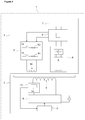
Figure 1 - is the schematic view of the communication system formed by an induction heating cooktop and a wireless kitchen appliance operated thereon. -
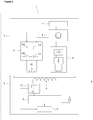
Figure 2 - is the schematic view of a communication system in an embodiment of the present invention. -
Figure 3 - is the schematic view of a communication system in another embodiment of the present invention. - The elements illustrated in the figures are numbered as follows:
- 1. Communication system
- 2. Cooktop
- 3. Appliance
- 4. Induction coil
- 5. Control unit
- 6. Inverter
- 7. User interface
- 8. Microcontroller
- 9. Voltage regulating circuitry
- 10. Receiver coil
- 11. Encoding unit
- 12. Decoding unit
- 13. 113, 213 Switching means
- 14. Current measuring unit
- 15. Phase difference measuring unit
- The communication system (1) comprises an induction heating cooktop (2) (referred to as "cooktop" hereinafter) and a kitchen appliance (3) (referred to as "appliance" hereinafter) suitable for using on the cooktop (2).
- The cooktop (2) comprises one or more than one induction coil (4), a control unit (5), for example a microprocessor, an inverter (6) that converts the AC mains voltage to DC voltage by switching and drives the induction coil (4).
- The appliance (3) comprises a user interface (7) having a display and a keypad that provide monitoring and controlling of the operating parameters like temperature, motor speed, one or more than one sensor (not shown in the figures), a microcontroller (8) in the memory of which the data relating to identification information and operating parameters of the appliance (3) are recorded and a voltage regulating circuitry (9) that supplies the microcontroller (8), the user interface (7) and the sensors with low value DC voltage by the power partially received from the induction coil (4).
- The communication system (1) of the present invention comprises a receiver coil (10) disposed in the appliance (3), that partially receives the power generated by the induction coil (4), an encoding unit (11) that changes the power received from the induction coil (4) by the receiver coil (10) by increasing/decreasing more than once depending on the appliance (3) identification information in the memory of the microcontroller (8) and the operating parameters entered by means of the user interface (7), and a decoding unit (12) disposed in the cooktop (2) which decodes the power change data received from the encoding unit (11) and delivers to the control unit (5), thereby provides the induction coil (4) to transfer power to the appliance (3) depending on the identification information detected by the control unit (5) and the operating parameters entered from the user interface (7).
- In an embodiment of the present invention, the decoding unit (12) decodes the power change information received from the encoding unit (11) by changing into on/off signal chains. The control unit (5) identifies the appliance (3) according to the characteristics of the on/off signal chains like the number of on/off signals, the period of each signal, detects the operating parameters entered from the user interface (7) and controls the operation of the induction coil (4) that delivers power to the appliance (3).
- While the appliance (3) is operated on the cooktop (2), first the power adjustment button on the cooktop (2) is brought to any adjustment position, for example the lowest level and power is transferred from the induction coil (4) to the appliance (3). The microcontroller (8) that is energized by means of the voltage regulating circuitry (9) operates the encoding unit (11) in accordance with the appliance (3) identification information located in its memory and the operating parameters entered by means of the user interface (7). The encoding unit (11) delivers power change data to the decoding unit (12) again through the induction coil (4) by increasing/decreasing the power received from the induction coil (4) by the receiver coil (10). The decoding unit (12) decodes the power change data received from the encoding unit (11) and converts into on/off signal chains that the control unit (5) can evaluate. Thus, the control unit (5) detects the identification information of the appliance (3) placed on the cooktop (2) and the operating parameters, for example temperature setting or motor speed, entered by means of the user interface (7) and provides the appliance (3) to be operated on the cooktop (2) at the desired power level. The power adjustment button on the cooktop (2) is used for only the initial energizing of the appliance (3). The appliance (3) controls the cooktop (2) depending on the operating parameters entered from the user interface (7). For example, if the appliance (3) is a kettle, a signal chain like "on/off/on/on/off/off" is generated in the decoding unit (12) and the control unit (5) detects that the appliance (3) is a kettle. When, for example, increase in power by means of the user interface (7) is desired, a signal chain of "off/on/on/on/on/on" is generated in the decoding unit (12) and the control unit (5) increases the power transferred from the induction coil (4). The communication system (1) provides the identification information and the operating parameters of the appliance (3) to be recognized by the cooktop (2) without using communication means like RFID, WIFI.
- In another embodiment of the present invention, the encoding unit (11) comprises one or more than one resistor (R1, R2) connected in parallel to the receiver coil (10) and one or more than one switching means (13) controlled by the microcontroller (8), connected in series to the resistors (R1, R2), and that provides the current received by the receiver coil (10) to be changed by actuating or deactuating the resistors (R1, R2).
- In another embodiment of the present invention, the encoding unit (11) comprises one or more than one resonant capacitor (C1, C2) connected in parallel to the receiver coil (10) and one or more switching means (113) controlled by the microcontroller (8), connected in series to the resonant capacitors (C1, C2), and that provides the current and the voltage received by the receiver coil (10) to be changed by actuating or deactuating the resonant capacitors (C1, C2).
- In another embodiment of the present invention, the communication system (1) comprises two receiver coils (10, 110) and the encoding unit (11) comprises a resistor (R3) and a switching means (213) controlled by the microcontroller (8), that provides the voltage received from the induction coil (4) to be changed by actuating or deactuating the first or the second receiver coil (10, 110).
- In yet another embodiment of the present invention, the decoding unit (12) comprises a current measuring unit (14), for example a peak current detector, that provides the detection and decoding of the power changes formed by the encoding unit (11) by measuring the current of the induction coil (4) or the current of the inverter (6).
- In another embodiment of the present invention, the decoding unit (12) comprises a phase difference measuring unit (15) that provides the detection and decoding of the power changes formed by the encoding unit (11) by monitoring the phase difference (time) between the induction coil (4) current or voltage and the zero crossings (ZC) of the inverter (6) voltage.
- The appliance (3) is an active heating appliance like the kettle, toaster having a resistant heater or an electromechanical appliance like mixer, chopper, mixer, blender, food processor that is operated with the electric motor.
- In the communication system (1) of the present invention, the identification information and the operating parameters of the appliance (3) are delivered to the cooktop (2) by means of an encoding unit (11) disposed in the appliance (3) and a decoding unit (12) disposed in the cooktop (2), and data transfer is provided without requiring the high cost and hard to use communication means like RFID, WIFI on the appliance (3) and the cooktop (2).
Claims (7)
- A communication system (1) comprising- a cooktop (2) having one or more than one induction coil (4), an inverter (6) that drives the induction coil (4) and a control unit (5), and- an appliance (3), suitable for being operated wirelessly on the cooktop (2), having a user interface (7) that provides monitoring and controlling of the operating parameters and a microcontroller (8) that contains the identification information and the operating parameters recorded in its memory,- a receiver coil (10) disposed in the appliance (3) that partially receives the power generated by the induction coil (4),characterized by- an encoding unit (11) disposed in the appliance (3) that changes the power received from the induction coil (4) by the receiver coil (10) by increasing/decreasing and- a decoding unit (12) disposed in the cooktop (2) which decodes the power change data received from the encoding unit (11) through the induction coil (4) and delivers the decoded data to the control unit (5).
- A communication system (1) as in claim 1, characterized by the decoding unit (12) that decodes the power change information received from the encoding unit (11) by changing into consecutive on/off signal chains.
- A communication system (1) as in claim 1 or 2, characterized by the encoding unit (11) comprising one or more than one resistor (R1, R2) connected in parallel to the receiver coil (10) and one or more than one switching means (13) connected in series to the resistors (R1, R2), and that provides the current received by the receiver coil (10) to be changed by actuating or deactuating the resistors (R1, R2).
- A communication system (1) as in claim 1 or 2, characterized by the encoding unit (11) comprising one or more than one resonant capacitor (C1, C2) connected in parallel to the receiver coil (10) and one or more than one switching means (113) connected in series to the resonant capacitors (C1, C2), and that provides the current and voltage received by the receiver coil (10) to be changed by actuating or deactuating the resonant capacitors (C1, C2).
- A communication system (1) as in claim 1 or 2, characterized by two receiver coils (10, 110) and the encoding unit (11) comprising a switching means (213) controlled by the microcontroller (8), that provides the voltage received from the induction coil (4) to be changed by actuating or deactuating the first or the second receiver coil (10, 110).
- A communication system (1) as in any one of the above claims, characterized by the decoding unit (12) comprising a current measuring unit (14), that provides detection of the power changes formed by the encoding unit (11) by measuring the current of the induction coil (4) or the current of the inverter (6).
- A communication system (1) as in any one of claims 1 to 5, characterized by the decoding unit (12) comprising a phase difference measuring unit (15), that provides detection of the power changes formed by the encoding unit (11) by monitoring the phase difference between the current or voltage of the induction coil (4) and the zero crossings (ZC) of the inverter (6).
Priority Applications (1)
| Application Number | Priority Date | Filing Date | Title |
|---|---|---|---|
| PL12812998T PL2798911T3 (en) | 2011-12-30 | 2012-12-21 | Induction heating cooktop communication system |
Applications Claiming Priority (2)
| Application Number | Priority Date | Filing Date | Title |
|---|---|---|---|
| TR201113315 | 2011-12-30 | ||
| PCT/EP2012/076664 WO2013098240A1 (en) | 2011-12-30 | 2012-12-21 | Induction heating cooktop communication system |
Publications (2)
| Publication Number | Publication Date |
|---|---|
| EP2798911A1 EP2798911A1 (en) | 2014-11-05 |
| EP2798911B1 true EP2798911B1 (en) | 2017-12-13 |
Family
ID=47522588
Family Applications (1)
| Application Number | Title | Priority Date | Filing Date |
|---|---|---|---|
| EP12812998.8A Revoked EP2798911B1 (en) | 2011-12-30 | 2012-12-21 | Induction heating cooktop communication system |
Country Status (5)
| Country | Link |
|---|---|
| EP (1) | EP2798911B1 (en) |
| CN (1) | CN104919894B (en) |
| PL (1) | PL2798911T3 (en) |
| TR (1) | TR201718728T4 (en) |
| WO (1) | WO2013098240A1 (en) |
Cited By (2)
| Publication number | Priority date | Publication date | Assignee | Title |
|---|---|---|---|---|
| WO2022223286A1 (en) * | 2021-04-19 | 2022-10-27 | BSH Hausgeräte GmbH | Induction energy transmission system |
| WO2022233660A1 (en) * | 2021-05-03 | 2022-11-10 | BSH Hausgeräte GmbH | Induction energy transmission system |
Families Citing this family (10)
| Publication number | Priority date | Publication date | Assignee | Title |
|---|---|---|---|---|
| EP3039944A1 (en) * | 2013-08-29 | 2016-07-06 | Arçelik Anonim Sirketi | Induction cooking appliance, wireless kitchen appliance and wireless communication system |
| FR3015210B1 (en) * | 2013-12-20 | 2016-01-01 | Seb Sa | INDUCTIVE CULINARY ARTICLE COMMUNICATING AND METHOD OF PAIRING SUCH A ARTICLE |
| EP3107176B1 (en) * | 2015-06-18 | 2018-04-04 | STMicroelectronics (Grand Ouest) SAS | Method for managing a wireless power transfer from an emitter to a receiver, and corresponding emitter |
| CN106604432A (en) * | 2015-10-20 | 2017-04-26 | 奇想生活股份有限公司 | Food heating treatment apparatus capable of receiving wireless electromagnetic energy |
| ES2729728A1 (en) * | 2018-05-04 | 2019-11-05 | Bsh Electrodomesticos Espana Sa | Induction power transmission system (Machine-translation by Google Translate, not legally binding) |
| DE102018212680A1 (en) | 2018-07-30 | 2020-01-30 | E.G.O. Elektro-Gerätebau GmbH | Method and device for inductive energy transmission |
| DE102019104003A1 (en) * | 2019-02-18 | 2020-08-20 | Miele & Cie. Kg | Method for the automatic assignment of an installation device to a hotplate of an inductive hob, installation device and system for carrying out the method |
| DE102020104130A1 (en) * | 2020-02-18 | 2021-08-19 | Miele & Cie. Kg | Cooking system and method of operation |
| EP3914042A1 (en) * | 2020-05-20 | 2021-11-24 | Infineon Technologies Austria AG | Cooking device, cookware and related methods |
| WO2023240309A1 (en) * | 2022-06-14 | 2023-12-21 | Breville Pty Limited | System and method of powering and communicating with accessories |
Family Cites Families (7)
| Publication number | Priority date | Publication date | Assignee | Title |
|---|---|---|---|---|
| JP3198628B2 (en) * | 1992-07-07 | 2001-08-13 | 松下電器産業株式会社 | Cordless equipment |
| AU2411599A (en) | 1998-02-10 | 1999-08-30 | Aktiebolaget Electrolux | A control system for use with induction heating cooktops |
| US20040016348A1 (en) * | 2002-07-24 | 2004-01-29 | Richard Sharpe | Electronic cooking pan systems and methods |
| US7355150B2 (en) * | 2006-03-23 | 2008-04-08 | Access Business Group International Llc | Food preparation system with inductive power |
| JP2012514495A (en) | 2009-01-06 | 2012-06-28 | アクセス ビジネス グループ インターナショナル リミテッド ライアビリティ カンパニー | Smart cookware |
| FR2945608A1 (en) * | 2009-05-15 | 2010-11-19 | Univ Angers | Method for controlling cooking temperature of cooking utensil, involves controlling heating device based on heat command so that temperature at interior of cooking utensil converges towards setpoint temperature |
| CN101924396B (en) * | 2009-06-16 | 2014-02-05 | 上海科勒电子科技有限公司 | Wireless charging/power supply system for sanitary appliance |
-
2012
- 2012-12-21 PL PL12812998T patent/PL2798911T3/en unknown
- 2012-12-21 TR TR2017/18728T patent/TR201718728T4/en unknown
- 2012-12-21 CN CN201280070964.2A patent/CN104919894B/en not_active Expired - Fee Related
- 2012-12-21 WO PCT/EP2012/076664 patent/WO2013098240A1/en active Application Filing
- 2012-12-21 EP EP12812998.8A patent/EP2798911B1/en not_active Revoked
Cited By (2)
| Publication number | Priority date | Publication date | Assignee | Title |
|---|---|---|---|---|
| WO2022223286A1 (en) * | 2021-04-19 | 2022-10-27 | BSH Hausgeräte GmbH | Induction energy transmission system |
| WO2022233660A1 (en) * | 2021-05-03 | 2022-11-10 | BSH Hausgeräte GmbH | Induction energy transmission system |
Also Published As
| Publication number | Publication date |
|---|---|
| PL2798911T3 (en) | 2018-05-30 |
| CN104919894A (en) | 2015-09-16 |
| CN104919894B (en) | 2017-08-29 |
| WO2013098240A1 (en) | 2013-07-04 |
| EP2798911A1 (en) | 2014-11-05 |
| TR201718728T4 (en) | 2018-03-21 |
Similar Documents
| Publication | Publication Date | Title |
|---|---|---|
| EP2798911B1 (en) | Induction heating cooktop communication system | |
| EP2878169B1 (en) | An induction heating cooktop and a wireless kitchen appliance | |
| EP2859776B1 (en) | A wireless kitchen appliance | |
| JP5894682B2 (en) | Wireless kitchen utensils operated on induction cooker | |
| JP5856026B2 (en) | System and method for food preparation | |
| US10454307B2 (en) | Wireless power apparatus, system and method | |
| JP5908993B2 (en) | Wireless kitchen utensils operated on induction cooker | |
| JP5894683B2 (en) | Wireless kitchen utensils operated on induction cooker | |
| WO2015032419A1 (en) | An individual cookware control device for use with an induction heating cooker, and wireless cooking system having the same | |
| TWI717752B (en) | Health pot heating device with wireless power supply | |
| CN112056941A (en) | Wireless power supply health preserving kettle heating device |
Legal Events
| Date | Code | Title | Description |
|---|---|---|---|
| PUAI | Public reference made under article 153(3) epc to a published international application that has entered the european phase |
Free format text: ORIGINAL CODE: 0009012 |
|
| 17P | Request for examination filed |
Effective date: 20140630 |
|
| AK | Designated contracting states |
Kind code of ref document: A1 Designated state(s): AL AT BE BG CH CY CZ DE DK EE ES FI FR GB GR HR HU IE IS IT LI LT LU LV MC MK MT NL NO PL PT RO RS SE SI SK SM TR |
|
| DAX | Request for extension of the european patent (deleted) | ||
| 17Q | First examination report despatched |
Effective date: 20161130 |
|
| GRAP | Despatch of communication of intention to grant a patent |
Free format text: ORIGINAL CODE: EPIDOSNIGR1 |
|
| INTG | Intention to grant announced |
Effective date: 20170811 |
|
| GRAS | Grant fee paid |
Free format text: ORIGINAL CODE: EPIDOSNIGR3 |
|
| GRAA | (expected) grant |
Free format text: ORIGINAL CODE: 0009210 |
|
| AK | Designated contracting states |
Kind code of ref document: B1 Designated state(s): AL AT BE BG CH CY CZ DE DK EE ES FI FR GB GR HR HU IE IS IT LI LT LU LV MC MK MT NL NO PL PT RO RS SE SI SK SM TR |
|
| REG | Reference to a national code |
Ref country code: GB Ref legal event code: FG4D |
|
| REG | Reference to a national code |
Ref country code: AT Ref legal event code: REF Ref document number: 955466 Country of ref document: AT Kind code of ref document: T Effective date: 20171215 Ref country code: CH Ref legal event code: EP |
|
| REG | Reference to a national code |
Ref country code: IE Ref legal event code: FG4D |
|
| REG | Reference to a national code |
Ref country code: DE Ref legal event code: R096 Ref document number: 602012040930 Country of ref document: DE |
|
| REG | Reference to a national code |
Ref country code: FR Ref legal event code: PLFP Year of fee payment: 6 |
|
| REG | Reference to a national code |
Ref country code: NL Ref legal event code: MP Effective date: 20171213 |
|
| REG | Reference to a national code |
Ref country code: LT Ref legal event code: MG4D |
|
| PG25 | Lapsed in a contracting state [announced via postgrant information from national office to epo] |
Ref country code: NO Free format text: LAPSE BECAUSE OF FAILURE TO SUBMIT A TRANSLATION OF THE DESCRIPTION OR TO PAY THE FEE WITHIN THE PRESCRIBED TIME-LIMIT Effective date: 20180313 Ref country code: LT Free format text: LAPSE BECAUSE OF FAILURE TO SUBMIT A TRANSLATION OF THE DESCRIPTION OR TO PAY THE FEE WITHIN THE PRESCRIBED TIME-LIMIT Effective date: 20171213 Ref country code: FI Free format text: LAPSE BECAUSE OF FAILURE TO SUBMIT A TRANSLATION OF THE DESCRIPTION OR TO PAY THE FEE WITHIN THE PRESCRIBED TIME-LIMIT Effective date: 20171213 Ref country code: SE Free format text: LAPSE BECAUSE OF FAILURE TO SUBMIT A TRANSLATION OF THE DESCRIPTION OR TO PAY THE FEE WITHIN THE PRESCRIBED TIME-LIMIT Effective date: 20171213 |
|
| REG | Reference to a national code |
Ref country code: AT Ref legal event code: MK05 Ref document number: 955466 Country of ref document: AT Kind code of ref document: T Effective date: 20171213 |
|
| PG25 | Lapsed in a contracting state [announced via postgrant information from national office to epo] |
Ref country code: RS Free format text: LAPSE BECAUSE OF FAILURE TO SUBMIT A TRANSLATION OF THE DESCRIPTION OR TO PAY THE FEE WITHIN THE PRESCRIBED TIME-LIMIT Effective date: 20171213 Ref country code: HR Free format text: LAPSE BECAUSE OF FAILURE TO SUBMIT A TRANSLATION OF THE DESCRIPTION OR TO PAY THE FEE WITHIN THE PRESCRIBED TIME-LIMIT Effective date: 20171213 Ref country code: GR Free format text: LAPSE BECAUSE OF FAILURE TO SUBMIT A TRANSLATION OF THE DESCRIPTION OR TO PAY THE FEE WITHIN THE PRESCRIBED TIME-LIMIT Effective date: 20180314 Ref country code: LV Free format text: LAPSE BECAUSE OF FAILURE TO SUBMIT A TRANSLATION OF THE DESCRIPTION OR TO PAY THE FEE WITHIN THE PRESCRIBED TIME-LIMIT Effective date: 20171213 Ref country code: BG Free format text: LAPSE BECAUSE OF FAILURE TO SUBMIT A TRANSLATION OF THE DESCRIPTION OR TO PAY THE FEE WITHIN THE PRESCRIBED TIME-LIMIT Effective date: 20180313 |
|
| PGFP | Annual fee paid to national office [announced via postgrant information from national office to epo] |
Ref country code: TR Payment date: 20180227 Year of fee payment: 7 |
|
| PG25 | Lapsed in a contracting state [announced via postgrant information from national office to epo] |
Ref country code: NL Free format text: LAPSE BECAUSE OF FAILURE TO SUBMIT A TRANSLATION OF THE DESCRIPTION OR TO PAY THE FEE WITHIN THE PRESCRIBED TIME-LIMIT Effective date: 20171213 |
|
| PG25 | Lapsed in a contracting state [announced via postgrant information from national office to epo] |
Ref country code: EE Free format text: LAPSE BECAUSE OF FAILURE TO SUBMIT A TRANSLATION OF THE DESCRIPTION OR TO PAY THE FEE WITHIN THE PRESCRIBED TIME-LIMIT Effective date: 20171213 Ref country code: CY Free format text: LAPSE BECAUSE OF FAILURE TO SUBMIT A TRANSLATION OF THE DESCRIPTION OR TO PAY THE FEE WITHIN THE PRESCRIBED TIME-LIMIT Effective date: 20171213 Ref country code: CZ Free format text: LAPSE BECAUSE OF FAILURE TO SUBMIT A TRANSLATION OF THE DESCRIPTION OR TO PAY THE FEE WITHIN THE PRESCRIBED TIME-LIMIT Effective date: 20171213 Ref country code: ES Free format text: LAPSE BECAUSE OF FAILURE TO SUBMIT A TRANSLATION OF THE DESCRIPTION OR TO PAY THE FEE WITHIN THE PRESCRIBED TIME-LIMIT Effective date: 20171213 Ref country code: SK Free format text: LAPSE BECAUSE OF FAILURE TO SUBMIT A TRANSLATION OF THE DESCRIPTION OR TO PAY THE FEE WITHIN THE PRESCRIBED TIME-LIMIT Effective date: 20171213 |
|
| REG | Reference to a national code |
Ref country code: CH Ref legal event code: PL |
|
| PG25 | Lapsed in a contracting state [announced via postgrant information from national office to epo] |
Ref country code: SM Free format text: LAPSE BECAUSE OF FAILURE TO SUBMIT A TRANSLATION OF THE DESCRIPTION OR TO PAY THE FEE WITHIN THE PRESCRIBED TIME-LIMIT Effective date: 20171213 Ref country code: AT Free format text: LAPSE BECAUSE OF FAILURE TO SUBMIT A TRANSLATION OF THE DESCRIPTION OR TO PAY THE FEE WITHIN THE PRESCRIBED TIME-LIMIT Effective date: 20171213 Ref country code: RO Free format text: LAPSE BECAUSE OF FAILURE TO SUBMIT A TRANSLATION OF THE DESCRIPTION OR TO PAY THE FEE WITHIN THE PRESCRIBED TIME-LIMIT Effective date: 20171213 Ref country code: IS Free format text: LAPSE BECAUSE OF FAILURE TO SUBMIT A TRANSLATION OF THE DESCRIPTION OR TO PAY THE FEE WITHIN THE PRESCRIBED TIME-LIMIT Effective date: 20180413 |
|
| REG | Reference to a national code |
Ref country code: DE Ref legal event code: R026 Ref document number: 602012040930 Country of ref document: DE |
|
| PLBI | Opposition filed |
Free format text: ORIGINAL CODE: 0009260 |
|
| REG | Reference to a national code |
Ref country code: IE Ref legal event code: MM4A |
|
| PG25 | Lapsed in a contracting state [announced via postgrant information from national office to epo] |
Ref country code: LU Free format text: LAPSE BECAUSE OF NON-PAYMENT OF DUE FEES Effective date: 20171221 Ref country code: MT Free format text: LAPSE BECAUSE OF NON-PAYMENT OF DUE FEES Effective date: 20171221 Ref country code: MC Free format text: LAPSE BECAUSE OF FAILURE TO SUBMIT A TRANSLATION OF THE DESCRIPTION OR TO PAY THE FEE WITHIN THE PRESCRIBED TIME-LIMIT Effective date: 20171213 |
|
| 26 | Opposition filed |
Opponent name: E.G.O. ELEKTRO-GERAETEBAU GMBH Effective date: 20180912 |
|
| REG | Reference to a national code |
Ref country code: BE Ref legal event code: MM Effective date: 20171231 |
|
| PG25 | Lapsed in a contracting state [announced via postgrant information from national office to epo] |
Ref country code: IE Free format text: LAPSE BECAUSE OF NON-PAYMENT OF DUE FEES Effective date: 20171221 |
|
| PLAX | Notice of opposition and request to file observation + time limit sent |
Free format text: ORIGINAL CODE: EPIDOSNOBS2 |
|
| PG25 | Lapsed in a contracting state [announced via postgrant information from national office to epo] |
Ref country code: LI Free format text: LAPSE BECAUSE OF NON-PAYMENT OF DUE FEES Effective date: 20171231 Ref country code: CH Free format text: LAPSE BECAUSE OF NON-PAYMENT OF DUE FEES Effective date: 20171231 Ref country code: DK Free format text: LAPSE BECAUSE OF FAILURE TO SUBMIT A TRANSLATION OF THE DESCRIPTION OR TO PAY THE FEE WITHIN THE PRESCRIBED TIME-LIMIT Effective date: 20171213 Ref country code: BE Free format text: LAPSE BECAUSE OF NON-PAYMENT OF DUE FEES Effective date: 20171231 |
|
| PGFP | Annual fee paid to national office [announced via postgrant information from national office to epo] |
Ref country code: DE Payment date: 20181210 Year of fee payment: 7 Ref country code: PL Payment date: 20181211 Year of fee payment: 7 |
|
| PG25 | Lapsed in a contracting state [announced via postgrant information from national office to epo] |
Ref country code: SI Free format text: LAPSE BECAUSE OF FAILURE TO SUBMIT A TRANSLATION OF THE DESCRIPTION OR TO PAY THE FEE WITHIN THE PRESCRIBED TIME-LIMIT Effective date: 20171213 |
|
| PGFP | Annual fee paid to national office [announced via postgrant information from national office to epo] |
Ref country code: GB Payment date: 20181218 Year of fee payment: 7 Ref country code: FR Payment date: 20181221 Year of fee payment: 7 |
|
| PGFP | Annual fee paid to national office [announced via postgrant information from national office to epo] |
Ref country code: IT Payment date: 20181220 Year of fee payment: 7 |
|
| PG25 | Lapsed in a contracting state [announced via postgrant information from national office to epo] |
Ref country code: HU Free format text: LAPSE BECAUSE OF FAILURE TO SUBMIT A TRANSLATION OF THE DESCRIPTION OR TO PAY THE FEE WITHIN THE PRESCRIBED TIME-LIMIT; INVALID AB INITIO Effective date: 20121221 |
|
| RAP2 | Party data changed (patent owner data changed or rights of a patent transferred) |
Owner name: ARCELIK ANONIM SIRKETI |
|
| PG25 | Lapsed in a contracting state [announced via postgrant information from national office to epo] |
Ref country code: MK Free format text: LAPSE BECAUSE OF FAILURE TO SUBMIT A TRANSLATION OF THE DESCRIPTION OR TO PAY THE FEE WITHIN THE PRESCRIBED TIME-LIMIT Effective date: 20171213 |
|
| REG | Reference to a national code |
Ref country code: DE Ref legal event code: R064 Ref document number: 602012040930 Country of ref document: DE Ref country code: DE Ref legal event code: R103 Ref document number: 602012040930 Country of ref document: DE |
|
| RDAF | Communication despatched that patent is revoked |
Free format text: ORIGINAL CODE: EPIDOSNREV1 |
|
| PG25 | Lapsed in a contracting state [announced via postgrant information from national office to epo] |
Ref country code: PT Free format text: LAPSE BECAUSE OF FAILURE TO SUBMIT A TRANSLATION OF THE DESCRIPTION OR TO PAY THE FEE WITHIN THE PRESCRIBED TIME-LIMIT Effective date: 20171213 |
|
| RDAG | Patent revoked |
Free format text: ORIGINAL CODE: 0009271 |
|
| STAA | Information on the status of an ep patent application or granted ep patent |
Free format text: STATUS: PATENT REVOKED |
|
| PG25 | Lapsed in a contracting state [announced via postgrant information from national office to epo] |
Ref country code: AL Free format text: LAPSE BECAUSE OF FAILURE TO SUBMIT A TRANSLATION OF THE DESCRIPTION OR TO PAY THE FEE WITHIN THE PRESCRIBED TIME-LIMIT Effective date: 20171213 |
|
| REG | Reference to a national code |
Ref country code: FI Ref legal event code: MGE |
|
| 27W | Patent revoked |
Effective date: 20200312 |
|
| GBPR | Gb: patent revoked under art. 102 of the ep convention designating the uk as contracting state |
Effective date: 20200312 |