EP2798750B1 - Interference reduction method and receiver - Google Patents
Interference reduction method and receiver Download PDFInfo
- Publication number
- EP2798750B1 EP2798750B1 EP12812836.0A EP12812836A EP2798750B1 EP 2798750 B1 EP2798750 B1 EP 2798750B1 EP 12812836 A EP12812836 A EP 12812836A EP 2798750 B1 EP2798750 B1 EP 2798750B1
- Authority
- EP
- European Patent Office
- Prior art keywords
- matrix
- eigenvalues
- eigenvectors
- covariance
- weighting
- Prior art date
- Legal status (The legal status is an assumption and is not a legal conclusion. Google has not performed a legal analysis and makes no representation as to the accuracy of the status listed.)
- Active
Links
Images

Classifications
-
- H—ELECTRICITY
- H04—ELECTRIC COMMUNICATION TECHNIQUE
- H04B—TRANSMISSION
- H04B7/00—Radio transmission systems, i.e. using radiation field
- H04B7/02—Diversity systems; Multi-antenna system, i.e. transmission or reception using multiple antennas
- H04B7/04—Diversity systems; Multi-antenna system, i.e. transmission or reception using multiple antennas using two or more spaced independent antennas
- H04B7/08—Diversity systems; Multi-antenna system, i.e. transmission or reception using multiple antennas using two or more spaced independent antennas at the receiving station
- H04B7/0837—Diversity systems; Multi-antenna system, i.e. transmission or reception using multiple antennas using two or more spaced independent antennas at the receiving station using pre-detection combining
- H04B7/0842—Weighted combining
- H04B7/0848—Joint weighting
- H04B7/0851—Joint weighting using training sequences or error signal
-
- H—ELECTRICITY
- H04—ELECTRIC COMMUNICATION TECHNIQUE
- H04L—TRANSMISSION OF DIGITAL INFORMATION, e.g. TELEGRAPHIC COMMUNICATION
- H04L1/00—Arrangements for detecting or preventing errors in the information received
- H04L1/004—Arrangements for detecting or preventing errors in the information received by using forward error control
- H04L1/0045—Arrangements at the receiver end
- H04L1/0055—MAP-decoding
Definitions
- This invention relates to a method for reducing interference in a multi-antenna receiver. It also relates to corresponding multi-antenna reception equipment and a computer program.
- a multi-antenna receiver comprises at least two reception antennas in order to receive replicas of the same signal emitted, thus introducing additional diversity and resulting in an improvement of the reception quality.
- the additional diversity provided is either spatial diversity if the two antennas are sufficiently distanced, or polarisation diversity if the antennas are co-located and polarised in different ways, or a share of both of these two types of diversity.
- the invention particularly relates to multicarrier transmission systems, for example of the OFDM (Orthogonal Frequency Division Multiplexing) type.
- multicarrier transmission provides frequency diversity that is independent of the spatial diversity and/or polarisation diversity provided by the use of several reception antennas.
- LTE Long Term Evolution
- TEDS TETRA Enhanced Data Service
- DAB Digital Audio Broadcasting
- DVB-T Digital Video Broadcasting-Terrestrial
- pilot symbols are known to the emitter and the receiver. They are generally used for synchronising and estimating the propagation channel.
- noise and interference are treated by comparing a signal that results from the combination of the signals received by the antennas of the receiver with an estimation of the signal emitted.
- an estimation of the emitted signal may be known in advance to the receiver, for example through the use of pilot symbols.
- the estimation of the signal emitted can also be obtained by the preliminary processing of the signals received on the different antennas, for example through a technique known under the name Maximum Ratio Combining (MRC).
- MRC Maximum Ratio Combining
- the document FR2924884 describes a method for reducing interference in a receiver comprising at least two antennas that each receive a signal transmitted through a radio propagation channel.
- the signals received and an estimation of the emitted signal are weighted using weighting vectors defined in vector sub-spaces representing the time and frequency variations of the propagation channel, for the signals received, and the convolution of the propagation channel with itself, for the estimation of the emitted signal.
- the method is more efficient than conventional methods using the MRC technique, the constraint imposed on the weighting vectors does however limit the performance of the method.
- This invention aims to improve the situation.
- the invention firstly concerns a method as claimed in claim 1.
- Pilot symbol means any symbol known to the receiver, that is both pilot symbols as designated in the standards of the known OFDM systems such as LTE and TEDS and/or synchronisation symbols and/or symbols that have already been demodulated and determined by the receiver in an earlier processing step.
- this invention makes it possible to optimally reduce the level of interference in a multi-antenna receiver and thus improve the Signal to Noise plus Interference Ratio (SNIR).
- MAP Maximum A Posterior
- SNIR Signal to Noise plus Interference Ratio
- the determination step comprises the sub-steps of:
- weighting vectors are homogeneous with the propagation channel.
- the covariance matrices G B and G D make it possible to represent the time and frequency constraints of that channel.
- the determination step further comprises a sub-step consisting in extracting a matrix C' B from the matrix C B and a matrix ⁇ ' B from the matrix ⁇ B , the matrix ⁇ B comprising a definite number n' B of eigenvalues of ⁇ B and the matrix C' B comprising the eigenvectors associated with these n' B eigenvalues, and a sub-step consisting in extracting a matrix C' D from the matrix C D and a matrix ⁇ ' D from the matrix ⁇ D , the matrix ⁇ ' D comprising a definite number n' D of eigenvalues of ⁇ D and the matrix C' D comprising the eigenvectors associated with those n' D eigenvalues, the weighting vectors being then determined with the help of the eigenvector matrices C' B and C ' D and eigenvalue matrices ⁇ ' B and ⁇ ' D .
- the n' B eigenvalues selected are the largest eigenvalues of the matrix ⁇ B and the n' D eigenvalues selected are the largest eigenvalues of the matrix ⁇ D .
- n' B and n' D are smaller than or equal to the number of pilot symbols in each frame.
- the covariance matrix G B is the Kronecker product of a covariance matrix G B,T in the time domain and a covariance matrix G B,F in the frequency domain
- the covariance matrix G D is the Kronecker product of a covariance matrix G D,T in the time domain and a covariance matrix G D,F in the frequency domain
- the determination step comprises the following sub-steps:
- a ⁇ B a 11 B ⁇ ⁇ a 1 n B ⁇ ⁇ ⁇ ⁇ a m 1 B ⁇ ⁇ a mn B .
- the emitted signal is a multicarrier signal, particularly an OFDM signal.
- the invention can also apply to single carrier systems.
- the invention also concerns a receiver as claimed in claim 7.
- the invention also relates to a computer program comprising instructions for implementing the method in to the invention when the program is executed by at least one processor.
- the chart in figure 3 is a schematic illustration of the execution of the computer program.
- Figure 1 represents reception equipment 2 of an OFDM transmission system, such as for example a base station or a mobile terminal of a PMR (Professional Mobile Radio) system of the TEDS type.
- PMR Professional Mobile Radio
- the receiver 2 comprises two antennas 4, 6 for the reception of two signals corresponding with the same OFDM signal transmitted from an emitter through two radio propagation channel associated with the antennas 4, 6.
- the channels associated with the antennas 4, 6 are assumed to meet identical physical constraints.
- the OFDM signal emitted by the emitter is organised in frames of symbols distributed in time and frequency, among which some symbols, called pilot symbols, are known to the receiver 2 and are stored in a memory 8 of the said receiver 2.
- Each frame thus comprises n symbol with n f subcarriers and n t time symbols, n being equal to the product of n f and n t .
- the receiver 2 comprises an input module 10 comprising stages for amplification, baseband forming, sampling and guard interval removal.
- the receiver 2 also comprises means 12 for the time-frequency conversion of the signals received by the antennas 4, 6 processed by the input module 10 to convert them from the time domain to the frequency domain.
- Those time frequency conversion means 12 use a Fast Fourier Transform.
- the receiver 2 further comprises an interference reduction module 14 that makes it possible to reduce the level of interference in a useful signal resulting from the combination of the signals received by the two antennas 4, 6.
- interference may be due, for example, to the presence of jammers emitting on the same radio channel as the emitter and/or the multiple signal propagation journeys.
- the interference reduction module 14 is capable of supplying data symbols in which the contribution of interference is minimised.
- a demodulator 16 of the receiver 2 makes it possible to demodulate those data symbols into demodulated bits using the same modulation technique as that used in the emitter.
- the demodulator 16 is further arranged to determine the likelihood of each demodulated bit.
- the likelihood of a bit has a negative or positive soft value, compared to a hard value such as the binary value "1" or "0" to indicate that the demodulator is delivering actual floating values, each with a sign that imposes a subsequent decision, by a decoder 18 of the receiver 2, about the status of the corresponding bit, that is to say a decision about the 'hard' value "0" or "1 ".
- the decoder 18 thus makes it possible to decode the demodulated bits supplied by the demodulator 16 on the basis of the likelihoods determined earlier.
- the decoder 18 implements decoding corresponding with the encoding used while emitting the signal, for example convolution decoding that corrects errors using the Viterbi algorithm.
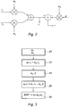
- Figure 2 illustrates the principle of the interference reduction method used by the interference reduction module 14.
- the principle used by this invention consists in applying weightings w 1 and w 2 respectively to the signals r 1 and r 2 , then combining the two weighted signals, for example by summing them, to obtain a signal r' from which an estimation of the emitted signal d weighted by weighting w d is subtracted.
- the resulting difference ⁇ represents a residual error.
- the method according to the invention advantageously uses the maximum a posteriori method to compute the most probable weightings knowing the error.
- the interference reduction module 14 weights the received signals r 1 and r 2 respectively by the weighting vectors w 1 and w 2 , the content of which is to be determined.
- the interference reduction module 14 combines, by summing them here, the signals r 1 and r 2 weighted to form a combined signal r'.
- step 24 the interference reduction module 14 weights a reference signal d, comprising the pilot symbols, with another weighting vector w d , the value of which is to be determined.
- the vectors w 1 , w 2 and w d are column vectors, each containing as many lines as symbols contained in the received signal, or n lines.
- step 26 the interference reduction module 14 determines an error ⁇ corresponding with the difference between the combined signal r' and the weighted reference signal.
- step 28 the interference reduction module 14 calculates the vectors w 1 , w 2 and w d using the MAP approach.
- the approach consists in maximising the probability of realisation of the weighting vector w. That probability is conditional upon the observation of the error ⁇ .
- weighting vectors w 1 , w 2 and w d are related to the propagation channel. That channel is dependent on constraints relating to its maximum time spread, due to reflections off far obstacles, and its maximum frequency speed, due to the speed of the reception equipment and the carrier frequency, that is the Doppler spread.
- the frequency spread of the channel due to reflections off near obstacles is limited.
- F p in which v is the speed of the receiver 2, c is the c speed of light and F p is the carrier frequency.
- the components of the frequency spectrum of the propagation channel along the frequency axis thus lie between these limits - F D and + F D .
- the time spread of the channel due to reflections off far obstacles is limited. That time spread depends on the frequency band used and the environment. For example, at a carrier frequency of 400 MHz in an urban environment, the time spread is of the order of 5 ⁇ s whereas in a mountainous environment, the spread is of the order of 15 ⁇ s.
- the components of the time response of channel are thus located between fixed limits for given environmental conditions.
- the limits of the frequency spectrum and the time response of the channel are known to the receiver 2 and are stored in the memory 8.
- the probability of realisation, expressing the MAP criterion of the weighting vector w is given by the following expression [1]:
- P w ⁇ ⁇ e ⁇ ⁇ R ⁇ w ⁇ 2 2.
- the variance , or power, ⁇ 2 is equal to:
- ⁇ 2 ⁇ 1 2 ⁇ w 1 ⁇ 2 + ⁇ 2 2 ⁇ w 2 ⁇ 2 , in which ⁇ 1 2 is the noise variance on the first antenna 4 and ⁇ 2 2 is the noise variance on the second antenna 6.
- the interference reduction module 14 aims to minimise that logarithm L ( P ( w )).
- the covariance matrix G is a block diagonal matrix constituted by concatenation of covariance matrices corresponding with each of the weighting vectors w 1 , w 2 and w d .
- the covariance matrix of w 1 is the same as that of w 2 , given that the two weighting vectors w 1 and w 2 are both homogeneous with a propagation channel, in the case of two reception antennas. That covariance matrix is noted G B and represents the time and frequency constraints relating to the propagation channel.
- the propagation vector w d is homogeneous with the convolution of two propagation channels, in the case of two reception antennas.
- the corresponding covariance matrix G D represents the time and frequency constraints relating to such a convolution.
- That constraint does not limit the solutions to the problem of the minimisation of the expression [2]. That is because regardless of the value of k 2 , the solution w does not change, as changing that constant would only multiply the solution by a scalar constraint.
- k 2 is fixed to 2. That makes it possible to consider that the weightings w 1 and w 2 each have unit power. Then the matrix G B is the standardised covariance matrix, that is to say it is obtained with average unit power of the channel, and the matrix G D is the covariance matrix corresponding with the convolution of two channels with unit power. As a result, ⁇ 2 represents the inverse of the signal to noise ratio observed on any one of the antennas.
- a target signal to noise ratio may be fixed, which value does not change regardless of the effective value of the noise power and the useful signal power.
- Other solutions are possible, such as estimating the signal to noise ratio as the information is received and demodulated, for example with pilot symbols that are known to the emitter and the receiver. In that case, it is possible to adapt the signal to noise ratio dynamically in the channel estimation process.
- N 1 0 ⁇ ⁇ ⁇ ⁇ ⁇ ⁇ 0 0 ⁇ ⁇ ⁇ ⁇ 1 ⁇ ⁇ ⁇ ⁇ 1 ⁇ ⁇ ⁇ ⁇ ⁇ ⁇ ⁇ ⁇ 1 ⁇ ⁇ ⁇ ⁇ 0 ⁇ ⁇ ⁇ ⁇ ⁇ 0 0 ⁇ ⁇ ⁇ ⁇ ⁇ ⁇ 0 0 ⁇ ⁇ ⁇ ⁇ ⁇ ⁇ 0 0 ⁇ ⁇ ⁇ ⁇ ⁇ 0 0 .
- the weighting vector w solution to the minimisation problem is thus a generalised eigenvector of both the term R H R 2.
- ⁇ 1 2 + H and the term N H N and ⁇ is the associated generalised eigenvalue.
- the weighting vector w minimising L ( P ( w )) is the generalised eigenvector corresponding with the smallest generalised eigenvalue ⁇ .
- the complexity of computation is further reduced by retaining only some eigenvalues of the covariance matrix G and the corresponding eigenvalues.
- a matrix C' is extracted from the matrix C and a matrix A' is extracted from the matrix A, the matrix A' comprising a definite number n' of eigenvalues of A and the matrix C' comprising the eigenvectors associated with those n' eigenvalues.
- the weighting vector w is then determined with the help of eigenvector matrices C' and eigenvalue matrices A'.
- the covariance matrix G is a block diagonal matrix, made up of the matrices G B , G B and G D , and for which each of the matrices G B and G D is the Kronecker product of a matrix G B,T , respectively G D,T , with covariance in the time domain, and a matrix G B,F , respectively G D,F , with covariance in the frequency domain, and the determination step includes the sub-steps of:
- the weighting vector w is then determined with the help of eigenvector matrices C ' B,T , C ' B,F , C ' D,T , C ' D,F and eigenvalue matrices ⁇ ' B,T , ⁇ ' B,T , ⁇ ' D,T , ⁇ ' D,F
- the interference reduction module 14 After determining the vector y from the previous expression, the interference reduction module 14 computes the weighting vector w according to the relation:
- the matrices C and A can advantageously be reduced by removing a certain number of their eigenvalues as described above.
- the covariance matrices may be computed dynamically in order to take account of the variations of the constraints of the channel.
Landscapes
- Engineering & Computer Science (AREA)
- Computer Networks & Wireless Communication (AREA)
- Signal Processing (AREA)
- Radio Transmission System (AREA)
- Noise Elimination (AREA)
Description
- This invention relates to a method for reducing interference in a multi-antenna receiver. It also relates to corresponding multi-antenna reception equipment and a computer program.
- A multi-antenna receiver comprises at least two reception antennas in order to receive replicas of the same signal emitted, thus introducing additional diversity and resulting in an improvement of the reception quality. The additional diversity provided is either spatial diversity if the two antennas are sufficiently distanced, or polarisation diversity if the antennas are co-located and polarised in different ways, or a share of both of these two types of diversity.
- The invention particularly relates to multicarrier transmission systems, for example of the OFDM (Orthogonal Frequency Division Multiplexing) type. Such multicarrier transmission provides frequency diversity that is independent of the spatial diversity and/or polarisation diversity provided by the use of several reception antennas.
- This type of transmission is used increasingly frequently. It has particularly been adopted in LTE (Long Term Evolution), TEDS (TETRA Enhanced Data Service), DAB (Digital Audio Broadcasting) and DVB-T (Digital Video Broadcasting-Terrestrial) systems.
- In OFDM transmission systems, data are generally organised in frames. In each frame, some symbols distributed in the time-frequency plane are inserted among the useful information intended for the receiver. These symbols, called "pilot symbols" are known to the emitter and the receiver. They are generally used for synchronising and estimating the propagation channel.
- Noise and interference affect the signal while it is being propagated between the emitter and the receiver and degrade signal reception. Deficient treatment of noise and interference then leads to a high rate of demodulation and decoding errors.
- Conventionally, noise and interference are treated by comparing a signal that results from the combination of the signals received by the antennas of the receiver with an estimation of the signal emitted. Such an estimation of the emitted signal may be known in advance to the receiver, for example through the use of pilot symbols. The estimation of the signal emitted can also be obtained by the preliminary processing of the signals received on the different antennas, for example through a technique known under the name Maximum Ratio Combining (MRC).
- The document
FR2924884 - This invention aims to improve the situation.
- To that end, the invention firstly concerns a method as claimed in
claim 1. - Pilot symbol means any symbol known to the receiver, that is both pilot symbols as designated in the standards of the known OFDM systems such as LTE and TEDS and/or synchronisation symbols and/or symbols that have already been demodulated and determined by the receiver in an earlier processing step.
- Thanks to the use of the Maximum A Posterior (MAP) approach, this invention makes it possible to optimally reduce the level of interference in a multi-antenna receiver and thus improve the Signal to Noise plus Interference Ratio (SNIR).
- Advantageously, the determination step comprises the sub-steps of:
- computation of a covariance matrix G B of the propagation channel;
- computation of a covariance matrix G D of the propagation channel convoluted with itself; and
- determination of the weighting vectors with the help of covariance matrices G B and G D .
- Indeed, the weighting vectors are homogeneous with the propagation channel. The covariance matrices G B and G D make it possible to represent the time and frequency constraints of that channel.
- Preferentially, the determination step further comprises a sub-step consisting in decomposing the covariance matrix G B into eigenvectors according to the relation G B =C B Λ B C B H in which C B is an eigenvector matrix of the matrix G B and Λ B is a diagonal matrix comprising the eigenvalues associated with the eigenvectors of the matrix G B and a sub-step consisting in decomposing the covariance matrix G D into eigenvectors according to the relation G D = C D Λ D C D H in which C D is an eigenvector matrix of the matrix G D and Λ D is a diagonal matrix comprising the eigenvalues associated with the eigenvectors of the matrix G D .
- These decompositions make it possible to simplify the computations of the weighting vectors.
- In one embodiment, the determination step further comprises a sub-step consisting in extracting a matrix C' B from the matrix C B and a matrix Λ' B from the matrix Λ B , the matrix Λ B comprising a definite number n'B of eigenvalues of Λ B and the matrix C' B comprising the eigenvectors associated with these n'B eigenvalues, and a sub-step consisting in extracting a matrix C' D from the matrix C D and a matrix Λ' D from the matrix Λ D , the matrix Λ' D comprising a definite number n'D of eigenvalues of Λ D and the matrix C' D comprising the eigenvectors associated with those n'D eigenvalues, the weighting vectors being then determined with the help of the eigenvector matrices C' B and C ' D and eigenvalue matrices Λ ' B and Λ ' D .
- Preferentially, the n'B eigenvalues selected are the largest eigenvalues of the matrix Λ B and the n'D eigenvalues selected are the largest eigenvalues of the matrix Λ D .
- That makes it possible to reduce the complexity of the weighting vectors while minimising the loss of performance thanks to the fact that the eigenvectors retained in the matrices C ' B and C ' D represent the largest part of the energy, represented by the sum of the eigenvalues retained in the matrices Λ ' B and Λ ' D .
- Preferentially, n'B and n'D are smaller than or equal to the number of pilot symbols in each frame.
- In a preferred embodiment, the covariance matrix G B is the Kronecker product of a covariance matrix G B,T in the time domain and a covariance matrix G B,F in the frequency domain and the covariance matrix G D is the Kronecker product of a covariance matrix G D,T in the time domain and a covariance matrix G D,F in the frequency domain, and the determination step comprises the following sub-steps:
- decomposition of the covariance matrices G B,T and G B,F into eigenvectors according to the relations G B,T = C B,T Λ B,T C B,T H and G B,F = C B,F Λ B,F C B,F H, in which:
- C B,T is an eigenvector matrix of the matrix G B,T ;
- Λ B,T is a diagonal matrix comprising eigenvalues associated with the eigenvectors of the matrix G B,T ;
- C B,F is an eigenvector matrix of the matrix G B,F ; and
- Λ B,F is a diagonal matrix comprising eigenvalues associated with the eigenvectors of the matrix G B,F;
- extraction of a matrix C ' B,T from the matrix C B,T and a matrix Λ ' B,T from the matrix Λ B,T , the matrix Λ ' B,T comprising a definite number nBt' of the largest eigenvalues of Λ B,T and the matrix C 'B,T comprising the eigenvectors associated with these nBt' largest eigenvalues;
- extraction of a matrix C ' B,F from the matrix C B,F and a matrix Λ ' B,F from the matrix Λ B,F , the matrix Λ ' B,F comprising a definite number nBf' of the largest eigenvalues of Λ B,F and the matrix C ' B,F comprising the eigenvectors associated with these nBf' largest eigenvalues,
- decomposition of the covariance matrices G D,T and G D,F into eigenvectors according to the relations G D,T = C D,T Λ D,T C D,T H and G D,F = C D,F Λ D,F C D,F H , in which:
- C D,T is an eigenvector matrix of the matrix G D,T ;
- Λ D,T is a diagonal matrix comprising eigenvalues associated with the eigenvectors of the matrix G D,T ;
- C D,F is an eigenvector matrix of the matrix G D,F ; and
- Λ D,F is a diagonal matrix comprising eigenvalues associated with the eigenvectors of the matrix G D,F ;
- extraction of a matrix C ' D,T from the matrix C D,T and a matrix Λ ' D,T from the matrix Λ D,T, the matrix Λ ' D,T comprising a definite number nDt' of the largest eigenvalues of Λ D,T and the matrix C ' D,T comprising the eigenvectors associated with these nDt' largest eigenvalues; and
- extraction of a matrix C ' D,F from the matrix C D,F and a matrix Λ ' D,F from the matrix Λ D,F , the matrix Λ ' D,F comprising a definite number nDf' of the largest eigenvalues of Λ D,F and the matrix C ' D,F comprising the eigenvectors associated with these nDf' largest eigenvalues,
- The Kronecker product of the two matrices A and B, the matrix A having the components (aij), where i is an integer between 1 and m and j is an integer between 1 and n, is the matrix product noted AⓍB and defined by the following expression:

- That use of the separability of the covariance matrix between the time domain and the frequency domain makes it possible to further reduce the complexity of the calculation of the weighting vectors while guaranteeing performance that is very close to that obtained by using the totality of the covariance matrix.
- Advantageously, the emitted signal is a multicarrier signal, particularly an OFDM signal.
- The invention can also apply to single carrier systems.
- The invention also concerns a receiver as claimed in claim 7.
- The invention also relates to a computer program comprising instructions for implementing the method in to the invention when the program is executed by at least one processor.
- The chart in
figure 3 is a schematic illustration of the execution of the computer program. - Embodiments of the invention will now be described in a more precise but non-limitative manner by reference to the drawings attached where:
-
figure 1 is a diagram of reception equipment according to the invention; -
figure 2 is a diagram illustrating the working principle of the interference reduction method; and -
figure 3 is a chart illustrating the working of the interference reduction method according to the invention. -
Figure 1 representsreception equipment 2 of an OFDM transmission system, such as for example a base station or a mobile terminal of a PMR (Professional Mobile Radio) system of the TEDS type. - The
receiver 2 comprises twoantennas antennas antennas - The OFDM signal emitted by the emitter is organised in frames of symbols distributed in time and frequency, among which some symbols, called pilot symbols, are known to the
receiver 2 and are stored in amemory 8 of the saidreceiver 2. Each frame thus comprises n symbol with nf subcarriers and nt time symbols, n being equal to the product of nf and nt. - The
receiver 2 comprises aninput module 10 comprising stages for amplification, baseband forming, sampling and guard interval removal. - The
receiver 2 also comprises means 12 for the time-frequency conversion of the signals received by theantennas input module 10 to convert them from the time domain to the frequency domain. Those time frequency conversion means 12 use a Fast Fourier Transform. - The
receiver 2 further comprises aninterference reduction module 14 that makes it possible to reduce the level of interference in a useful signal resulting from the combination of the signals received by the twoantennas - The
interference reduction module 14 is capable of supplying data symbols in which the contribution of interference is minimised. - A
demodulator 16 of thereceiver 2 makes it possible to demodulate those data symbols into demodulated bits using the same modulation technique as that used in the emitter. Thedemodulator 16 is further arranged to determine the likelihood of each demodulated bit. The likelihood of a bit has a negative or positive soft value, compared to a hard value such as the binary value "1" or "0" to indicate that the demodulator is delivering actual floating values, each with a sign that imposes a subsequent decision, by adecoder 18 of thereceiver 2, about the status of the corresponding bit, that is to say a decision about the 'hard' value "0" or "1 ". - The
decoder 18 thus makes it possible to decode the demodulated bits supplied by thedemodulator 16 on the basis of the likelihoods determined earlier. Thedecoder 18 implements decoding corresponding with the encoding used while emitting the signal, for example convolution decoding that corrects errors using the Viterbi algorithm. -
Figure 2 illustrates the principle of the interference reduction method used by theinterference reduction module 14. - By noting the signals received on
antennas - The method according to the invention advantageously uses the maximum a posteriori method to compute the most probable weightings knowing the error.
- The steps of the method are described by reference to the chart in
figure 3 . - During a
first step 20, theinterference reduction module 14 weights the received signals r1 and r2 respectively by the weighting vectors w 1 and w 2, the content of which is to be determined. - In
step 22, theinterference reduction module 14 combines, by summing them here, the signals r1 and r2 weighted to form a combined signal r'. - In
step 24, theinterference reduction module 14 weights a reference signal d, comprising the pilot symbols, with another weighting vector w d , the value of which is to be determined. - The vectors w 1, w 2 and w d are column vectors, each containing as many lines as symbols contained in the received signal, or n lines.
- In
step 26, theinterference reduction module 14 determines an error ε corresponding with the difference between the combined signal r' and the weighted reference signal. - Thus, by noting as w the vector consisting in a concatenation of the vectors w 1, w 2 and w d and R, the matrix comprising the signals received and the reference signal defined according to the expression:

- In
step 28, theinterference reduction module 14 calculates the vectors w 1, w 2 and w d using the MAP approach. - The approach consists in maximising the probability of realisation of the weighting vector w. That probability is conditional upon the observation of the error ε.
- Using Bayes' formula, that probability is equal to the probability that the error ε is observed conditionally upon the probability that the weighting is equal to the vector w, that conditional probability being multiplied by the probability that the weighting vector w is realised. That is expressed by the following relation:

- But the weighting vectors w 1, w 2 and w d are related to the propagation channel. That channel is dependent on constraints relating to its maximum time spread, due to reflections off far obstacles, and its maximum frequency speed, due to the speed of the reception equipment and the carrier frequency, that is the Doppler spread.
- Firstly, in the frequency domain, the frequency spread of the channel, called the Doppler spread, due to reflections off near obstacles is limited. The spread ranges between - FD and + FD, where FD is the maximum Doppler frequency given by the relation

receiver 2, c is the c speed of light and Fp is the carrier frequency. The components of the frequency spectrum of the propagation channel along the frequency axis thus lie between these limits - FD and + FD. - Secondly, the time spread of the channel due to reflections off far obstacles is limited. That time spread depends on the frequency band used and the environment. For example, at a carrier frequency of 400 MHz in an urban environment, the time spread is of the order of 5 µs whereas in a mountainous environment, the spread is of the order of 15 µs. The components of the time response of channel are thus located between fixed limits for given environmental conditions.
- The limits of the frequency spectrum and the time response of the channel are known to the
receiver 2 and are stored in thememory 8. - These characteristics of the propagation channel are represented by a matrix called the overall covariance matrix G.
- Due to the constraints expressed in the overall covariance matrix G, the probability of occurrence of the weighting vector w is given by the expression:

- Further, under the hypothesis that the channel noise is of the Gaussian type, the conditional probability of observation of the error ε is given by the expression:

- Thus, the probability of realisation, expressing the MAP criterion of the weighting vector w is given by the following expression [1]:


first antenna 4 and
second antenna 6. - Assuming that the noise power is the same on both antennas, that is that


- Taking the opposite of the logarithm of the expression [1], the following expression [2] is obtained:

- The
interference reduction module 14 aims to minimise that logarithm L(P(w)). - Besides, the covariance matrix G is a block diagonal matrix constituted by concatenation of covariance matrices corresponding with each of the weighting vectors w 1, w 2 and w d .
- The covariance matrix of w 1 is the same as that of w 2, given that the two weighting vectors w 1 and w 2 are both homogeneous with a propagation channel, in the case of two reception antennas. That covariance matrix is noted G B and represents the time and frequency constraints relating to the propagation channel.
- The propagation vector w d is homogeneous with the convolution of two propagation channels, in the case of two reception antennas. The corresponding covariance matrix G D represents the time and frequency constraints relating to such a convolution.
The covariance matrix G could thus be written thus:

- That constraint does not limit the solutions to the problem of the minimisation of the expression [2]. That is because regardless of the value of k2, the solution w does not change, as changing that constant would only multiply the solution by a scalar constraint.
- In what follows, k2 is fixed to 2. That makes it possible to consider that the weightings w1 and w2 each have unit power. Then the matrix G B is the standardised covariance matrix, that is to say it is obtained with average unit power of the channel, and the matrix GD is the covariance matrix corresponding with the convolution of two channels with unit power. As a result, σ2 represents the inverse of the signal to noise ratio observed on any one of the antennas.
- A target signal to noise ratio may be fixed, which value does not change regardless of the effective value of the noise power and the useful signal power. Other solutions are possible, such as estimating the signal to noise ratio as the information is received and demodulated, for example with pilot symbols that are known to the emitter and the receiver. In that case, it is possible to adapt the signal to noise ratio dynamically in the channel estimation process.
- The expression [2] may thus be written:

- The minimisation problem of
step 28 is thus a problem of optimisation with a constraint, which is resolved with Lagrange multipliers according to the following relation:
antennas - In other terms, the matrix N may be written:

- The minimisation of the gradient then provides the following expression [3]:

- The weighting vector w solution to the minimisation problem is thus a generalised eigenvector of both the term

- Further, the solution must verify the relation L(P(w)) = µ + cst.
- Thus, the weighting vector w minimising L(P(w)) is the generalised eigenvector corresponding with the smallest generalised eigenvalue µ.
- In a preferred embodiment, in order to reduce the complexity of the computations, the covariance matrices G B and G D are decomposed in
step 28 into eigenvectors and eigenvalues in the following manner: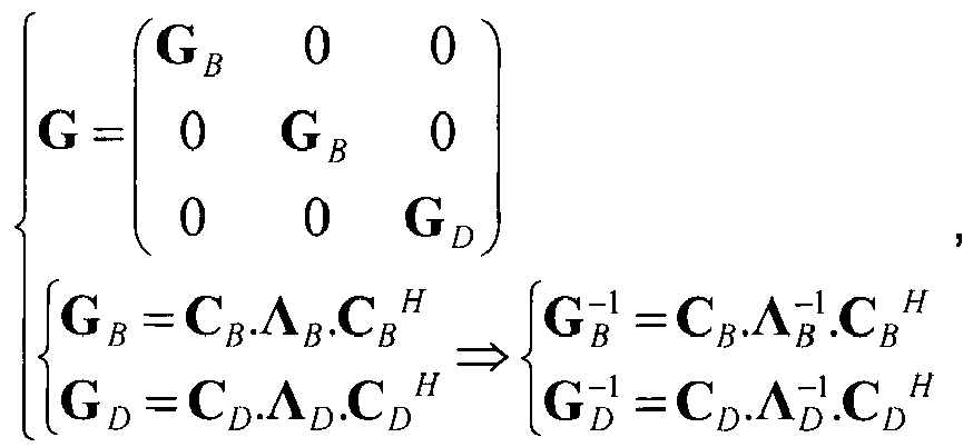
- The covariance matrix G may thus be written G =CΛC H , where C is an eigenvector matrix of the matrix G and A is a diagonal matrix comprising eigenvalues associated with the eigenvectors of the matrix G.
- Thus, the inverse matrix of the covariance matrix G is equal to:

- In one embodiment, the complexity of computation is further reduced by retaining only some eigenvalues of the covariance matrix G and the corresponding eigenvalues. In that case, a matrix C' is extracted from the matrix C and a matrix A' is extracted from the matrix A, the matrix A' comprising a definite number n' of eigenvalues of A and the matrix C' comprising the eigenvectors associated with those n' eigenvalues. The weighting vector w is then determined with the help of eigenvector matrices C' and eigenvalue matrices A'.
- In a preferred embodiment, the covariance matrix G is a block diagonal matrix, made up of the matrices G B , G B and G D , and for which each of the matrices G B and G D is the Kronecker product of a matrix G B,T , respectively G D,T, with covariance in the time domain, and a matrix G B,F, respectively G D,F , with covariance in the frequency domain, and the determination step includes the sub-steps of:
- decomposition of the covariance matrices G B,T and G B,F into eigenvectors according to the relations G B,T = C B,T Λ B,T C B,T H and G B,F =C B,F Λ B,T C B,F H , in which:
- C B,T is an eigenvector matrix of the matrix G B,T;
- Λ B,T is a diagonal matrix comprising eigenvalues associated with the eigenvectors of the matrix G B,T;
- C B,F is an eigenvector matrix of the matrix G B,F ; and
- Λ B,F is a diagonal matrix comprising eigenvalues associated with the eigenvectors of the matrix G B,F ;
- extraction of a matrix C ' B,T from the matrix C B,T and a matrix Λ ' B,T from the matrix Λ B,T , the matrix Λ ' B,T comprising a definite number nBt' of the largest eigenvalues of Λ B,T and the matrix C ' B,T comprising the eigenvectors associated with these nBt' largest eigenvalues; and
- extraction of a matrix C ' B,F from the matrix C B,F and a matrix Λ ' B,F from the matrix Λ B,F the matrix Λ ' B,F comprising a definite number nBf' of the largest eigenvalues of Λ B,F and the matrix C B,F comprising the eigenvectors associated with these nBf' largest eigenvalues.
- decomposition of the covariance matrices G D,T and G D,F into eigenvectors according to the relations G D,T = C D,T Λ D,T C D,T H and G D,F = C D,F Λ D,F C D,F H , in which:
- C D,T is an eigenvector matrix of the matrix G D,T ;
- Λ D,T is a diagonal matrix comprising eigenvalues associated with the eigenvectors of the matrix G D,T ;
- C D,F is an eigenvector matrix of the matrix G D,F ; and
- Λ D,F is a diagonal matrix comprising eigenvalues associated with the eigenvectors of the matrix G D,F ;
- extraction of a matrix C ' D,T from the matrix C D,T and a matrix Λ ' D,T from the matrix Λ D,T , the matrix Λ ' D,T comprising a definite number nDt' of the largest eigenvalues of Λ D,T and the matrix C ' D,T comprising the eigenvectors associated with these nDt' largest eigenvalues; and
- extraction of a matrix C ' D,F from the matrix C D,F and a matrix Λ ' D,F from the matrix Λ D,F , the matrix Λ ' D,F comprising a definite number nDf' of the largest eigenvalues of Λ D,F and the matrix C ' D,F comprising the eigenvectors associated with these nDf' largest eigenvalues.
- The weighting vector w is then determined with the help of eigenvector matrices C ' B,T , C ' B,F , C ' D,T, C ' D,F and eigenvalue matrices Λ ' B,T, Λ ' B,T , Λ ' D,T , Λ ' D,F
- Going back to the expression [3] and using the decomposition into eigenvectors and eigenvalues of the covariance matrix, one obtains:

- After determining the vector y from the previous expression, the
interference reduction module 14 computes the weighting vector w according to the relation: - w=C.y.
- In the equation above, the matrices C and A can advantageously be reduced by removing a certain number of their eigenvalues as described above.
- Of course, other embodiments may also be envisaged.
- More particularly, the covariance matrices may be computed dynamically in order to take account of the variations of the constraints of the channel.
- It is also possible to take account of other parameters while computing the covariance matrices, particularly delay profiles etc.
Claims (8)
- A method for reducing interference in a receiver (2) comprising at least two antennas (4, 6), each receiving a signal transmitted through an associated radio propagation channel, the received signals corresponding with the same emitted signal comprising frames of symbols distributed in time and frequency, among which some symbols, called pilot symbols, are known to the receiver, where the said method comprises the following steps:- weighting (20) of each of the signals received with a weighting vector associated respectively with a respective antenna of the receiver;- combination (22) of the weighted signals received to obtain a combined received signal;- weighting (24) of a reference signal comprising pilot symbols with another weighting vector;- comparison (26) of the combined received signal and the weighted reference signal to obtain an error; the said method being characterized in that it comprises the following step:- determination (28) of the weighting vectors using a maximum a posteriori criterion by maximising a probability of realisation of the said weighting vectors conditionally with the error obtained.
- A method according to claim 1, in which the determination step (28) includes the following sub-steps:- computation of a covariance matrix G B of the propagation channel;- computation of a covariance matrix G D of the propagation channel convoluted with itself; and- determination of the weighting vectors using covariance matrices G B and G D .
- A method according to claim 2, wherein the determination step (28) further comprises a sub-step consisting in decomposing the covariance matrix G B into eigenvectors according to the relation G B = C B Λ B C B H in which C B is an eigenvector matrix of the matrix G B and Λ B is a diagonal matrix comprising the eigenvalues associated with the eigenvectors of the matrix G B and a sub-step consisting in decomposing the covariance matrix G D into eigenvectors according to the relation G D = C D Λ D C D H in which C D is an eigenvector matrix of the matrix G D and Λ D is a diagonal matrix comprising the eigenvalues associated with the eigenvectors of the matrix G D .
- A method according to claim 3, wherein the determination step (28) further comprises a sub-step consisting in extracting a matrix C ' B from the matrix C B and a matrix Λ' B from the matrix Λ B , the matrix Λ ' B comprising a definite number nB' of eigenvalues of Λ B and the matrix C 'B comprising the eigenvectors associated with these nB' eigenvalues, and a sub-step consisting in extracting a matrix C 'D from the matrix C D and a matrix Λ ' D from the matrix Λ D , the matrix Λ 'D comprising a definite number nD' of eigenvalues of Λ D and the matrix C 'D comprising the eigenvectors associated with those nD' eigenvalues, the weighting vectors being then determined using the eigenvector matrices C ' B and C 'D and
eigenvalue matrices Λ 'B and Λ 'D . - A method according to claim 3, wherein the covariance matrix G B is the Kronecker product of a covariance matrix G B,T in the time domain and a covariance matrix G B,F in the frequency domain and the covariance matrix G D is the Kronecker product of a covariance matrix G D,T in the time domain and a covariance matrix G D,F in the frequency domain, and the determination step (28) comprises the following sub-steps:- decomposition of the covariance matrices G B,T and G B,F into eigenvectors according to the relations G B,T = C B,T Λ B,T C B,T H and G B,F = C B,F Λ B,F C B,F H , in which:- C B,T is an eigenvector matrix of the matrix G B,T ;- Λ B,T is a diagonal matrix comprising eigenvalues associated with the eigenvectors of the matrix G B,T ;- C B,F is an eigenvector matrix of the matrix G B,F ; and- Λ B,F is a diagonal matrix comprising eigenvalues associated with the eigenvectors of the matrix G B,F ;- extraction of a matrix C 'B,T from the matrix C B,T and a matrix Λ 'B,T from the matrix Λ B,T , the matrix Λ 'B,T comprising a definite number nBt' of the largest eigenvalues of Λ B,T and the matrix C ' B,T comprising the eigenvectors associated with these nBt' largest eigenvalues;- extraction of a matrix C ' B,F from the matrix C B,F and a matrix Λ ' B,F from the matrix Λ B,F , the matrix Λ ' B,F comprising a definite number nBf' of the largest eigenvalues of Λ B,F and the matrix C ' B,F comprising the eigenvectors associated with these nBf' largest eigenvalues,- decomposition of the covariance matrices G D,T and G D,T into eigenvectors according to the relations G D,T = C D,T Λ D,T C D,T H and G D,F = C D,F Λ D,F C D,F H, in which:- C D,T is an eigenvector matrix of the matrix G D,T;- Λ D,T is a diagonal matrix comprising eigenvalues associated with the eigenvectors of the matrix G D,T;- C D,F is an eigenvector matrix of the matrix G D,F ; and- Λ D,F is a diagonal matrix comprising eigenvalues associated with the eigenvectors of the matrix G D,F;- extraction of a matrix C ' D,T from the matrix C D,T and a matrix Λ ' D,T from the matrix Λ D,T, the matrix Λ ' D,T comprising a definite number nDt' of the largest eigenvalues of Λ D,T and the matrix C ' D,T comprising the eigenvectors associated with these nDt' largest eigenvalues; and- extraction of a matrix C ' D,F from the matrix C D,F and a matrix Λ ' D,F from the matrix Λ D,F , the matrix Λ ' D,F comprising a definite number nDf' of the largest eigenvalues of Λ D,F and the matrix C ' D,F comprising the eigenvectors associated with these nDf' largest eigenvalues, the weighting vectors being then determined using the eigenvector matrices C ' B,T, C ' B,F , C ' D,T, C ' D,F and the eigenvalue matrices Λ' B,T, Λ ' B,F , Λ ' D,T , Λ ' D,F.
- A method according to any of the previous claims, in which the emitted signal is a multicarrier signal, particularly an OFDM signal.
- Receiver (2) comprising at least two antennas (4, 6) capable, each, of receiving a signal transmitted through an associated radio propagation channel, the received signals corresponding with the same emitted signal comprising frames of symbols distributed in time and frequency, among which some symbols, called pilot symbols, are known to the receiver, where the said receiver comprises means (14) for the following:- weighting of each of the signals received with a weighting vector associated respectively with a respective antenna of the receiver;- combination of the weighted signals received to obtain a combined received signal;- weighting of a reference signal comprising pilot symbols with another weighting vector;- comparison of the combined received signal and the weighted reference signal to obtain an error; the said receiver being characterized in that it comprises means (14) for the following:- determination of the weighting vectors using a maximum a posteriori criterion by maximising a probability of realisation of the said weighting vectors conditionally with the error obtained.
- A computer program comprising instructions for implementing the method according to any of claims 1 to 6 when the program is executed by at least one processor.
Applications Claiming Priority (2)
| Application Number | Priority Date | Filing Date | Title |
|---|---|---|---|
| FR1161062A FR2983667B1 (en) | 2011-12-01 | 2011-12-01 | INTERFERENCE REDUCTION METHOD |
| PCT/EP2012/004911 WO2013079191A1 (en) | 2011-12-01 | 2012-11-28 | Interference reduction method |
Publications (2)
| Publication Number | Publication Date |
|---|---|
| EP2798750A1 EP2798750A1 (en) | 2014-11-05 |
| EP2798750B1 true EP2798750B1 (en) | 2017-04-05 |
Family
ID=47522433
Family Applications (1)
| Application Number | Title | Priority Date | Filing Date |
|---|---|---|---|
| EP12812836.0A Active EP2798750B1 (en) | 2011-12-01 | 2012-11-28 | Interference reduction method and receiver |
Country Status (5)
| Country | Link |
|---|---|
| US (1) | US9467218B2 (en) |
| EP (1) | EP2798750B1 (en) |
| ES (1) | ES2624983T3 (en) |
| FR (1) | FR2983667B1 (en) |
| WO (1) | WO2013079191A1 (en) |
Families Citing this family (3)
| Publication number | Priority date | Publication date | Assignee | Title |
|---|---|---|---|---|
| FR3002709B1 (en) | 2013-02-22 | 2015-03-06 | Cassidian Sas | METHOD FOR DEMODULATING A SIGNAL |
| JP2016127440A (en) * | 2015-01-05 | 2016-07-11 | 富士通株式会社 | Wireless communication system, wireless communication method, transmitter, and control method for transmitter |
| CN113282882B (en) * | 2021-05-25 | 2025-12-12 | 中国计量科学研究院 | A method, apparatus, device, and storage medium for generating a standard reference signal. |
Family Cites Families (4)
| Publication number | Priority date | Publication date | Assignee | Title |
|---|---|---|---|---|
| JP2001333002A (en) * | 2000-05-24 | 2001-11-30 | Ntt Docomo Inc | Transmit antenna weight estimation method and mobile communication terminal in mobile communication system |
| FI20065220A0 (en) * | 2006-04-04 | 2006-04-04 | Nokia Corp | Receiver and Receiving Method |
| WO2008060105A1 (en) * | 2006-11-15 | 2008-05-22 | Lg Electronics Inc. | Data transmission method using dirty paper coding in mimo system |
| FR2924884B1 (en) * | 2007-12-11 | 2009-12-04 | Eads Secure Networks | REDUCTION OF INTERFERENCES IN AN ORTHOGONAL FREQUENCY-DISTRIBUTED SIGNAL |
-
2011
- 2011-12-01 FR FR1161062A patent/FR2983667B1/en not_active Expired - Fee Related
-
2012
- 2012-11-28 EP EP12812836.0A patent/EP2798750B1/en active Active
- 2012-11-28 ES ES12812836.0T patent/ES2624983T3/en active Active
- 2012-11-28 US US14/362,199 patent/US9467218B2/en not_active Expired - Fee Related
- 2012-11-28 WO PCT/EP2012/004911 patent/WO2013079191A1/en not_active Ceased
Non-Patent Citations (1)
| Title |
|---|
| None * |
Also Published As
| Publication number | Publication date |
|---|---|
| EP2798750A1 (en) | 2014-11-05 |
| WO2013079191A1 (en) | 2013-06-06 |
| FR2983667A1 (en) | 2013-06-07 |
| US9467218B2 (en) | 2016-10-11 |
| FR2983667B1 (en) | 2014-01-03 |
| ES2624983T3 (en) | 2017-07-18 |
| US20140321584A1 (en) | 2014-10-30 |
Similar Documents
| Publication | Publication Date | Title |
|---|---|---|
| EP2533449B1 (en) | Transmitter apparatus, receiver apparatus, wireless communication system, transmission control method, reception control method, and processor | |
| US8121210B2 (en) | Apparatus and method for signal detection in multiple input multiple output wireless communication system | |
| US20080008258A1 (en) | Wireless receiving apparatus and method | |
| US8374298B2 (en) | Receiving apparatus and method | |
| US20110286412A1 (en) | Communication apparatus | |
| EP2228955B1 (en) | System and method for OFDM reception in the presense of Doppler effect based on time domain windowing | |
| US8824605B2 (en) | Receiving device, receiving method, receiving program, and processor | |
| EP2442507B1 (en) | Channel estimation method using an improved Expectation Maximization (EM-)Algorithm | |
| US7519125B2 (en) | Multicarrier receiver and methods of generating spatial correlation estimates for signals received with a plurality of antennas | |
| US8184733B2 (en) | Radio reception device, radio transmission device, radio base station, reception method, and transmission method | |
| US9467218B2 (en) | Interference reduction method | |
| US20120213315A1 (en) | Process for estimating the channel in a ofdm communication system, and receiver for doing the same | |
| EP2786540B1 (en) | Method for estimating a radio channel | |
| US8982979B2 (en) | Methods and systems for reducing complexity of MIMO decoder | |
| US9391740B2 (en) | Method for demodulating a signal | |
| US9059751B2 (en) | Systems and methods for multiplicative superposition for MIMO broadcast channels | |
| US9755769B2 (en) | Method for estimating a radioelectric propagation channel | |
| EP2651085A1 (en) | Method and apparatus for iterative detection of data streams | |
| EP2317665B1 (en) | Technique for transmitted streams combining weight determination in a receiver of a SIMO or MIMO system | |
| EP3139528B1 (en) | Communication device and method for signal determination in radio communication | |
| JP2013126144A (en) | Transmitter, receiver, and communication system | |
| US20160065266A1 (en) | Receiving device and receiving process method |
Legal Events
| Date | Code | Title | Description |
|---|---|---|---|
| PUAI | Public reference made under article 153(3) epc to a published international application that has entered the european phase |
Free format text: ORIGINAL CODE: 0009012 |
|
| 17P | Request for examination filed |
Effective date: 20140710 |
|
| AK | Designated contracting states |
Kind code of ref document: A1 Designated state(s): AL AT BE BG CH CY CZ DE DK EE ES FI FR GB GR HR HU IE IS IT LI LT LU LV MC MK MT NL NO PL PT RO RS SE SI SK SM TR |
|
| DAX | Request for extension of the european patent (deleted) | ||
| GRAP | Despatch of communication of intention to grant a patent |
Free format text: ORIGINAL CODE: EPIDOSNIGR1 |
|
| INTG | Intention to grant announced |
Effective date: 20161206 |
|
| GRAS | Grant fee paid |
Free format text: ORIGINAL CODE: EPIDOSNIGR3 |
|
| GRAA | (expected) grant |
Free format text: ORIGINAL CODE: 0009210 |
|
| AK | Designated contracting states |
Kind code of ref document: B1 Designated state(s): AL AT BE BG CH CY CZ DE DK EE ES FI FR GB GR HR HU IE IS IT LI LT LU LV MC MK MT NL NO PL PT RO RS SE SI SK SM TR |
|
| REG | Reference to a national code |
Ref country code: GB Ref legal event code: FG4D |
|
| REG | Reference to a national code |
Ref country code: CH Ref legal event code: EP |
|
| REG | Reference to a national code |
Ref country code: AT Ref legal event code: REF Ref document number: 882706 Country of ref document: AT Kind code of ref document: T Effective date: 20170415 |
|
| REG | Reference to a national code |
Ref country code: IE Ref legal event code: FG4D |
|
| REG | Reference to a national code |
Ref country code: DE Ref legal event code: R096 Ref document number: 602012030858 Country of ref document: DE |
|
| REG | Reference to a national code |
Ref country code: ES Ref legal event code: FG2A Ref document number: 2624983 Country of ref document: ES Kind code of ref document: T3 Effective date: 20170718 |
|
| REG | Reference to a national code |
Ref country code: NL Ref legal event code: MP Effective date: 20170405 |
|
| REG | Reference to a national code |
Ref country code: LT Ref legal event code: MG4D |
|
| REG | Reference to a national code |
Ref country code: AT Ref legal event code: MK05 Ref document number: 882706 Country of ref document: AT Kind code of ref document: T Effective date: 20170405 |
|
| PG25 | Lapsed in a contracting state [announced via postgrant information from national office to epo] |
Ref country code: NL Free format text: LAPSE BECAUSE OF FAILURE TO SUBMIT A TRANSLATION OF THE DESCRIPTION OR TO PAY THE FEE WITHIN THE PRESCRIBED TIME-LIMIT Effective date: 20170405 |
|
| REG | Reference to a national code |
Ref country code: FR Ref legal event code: PLFP Year of fee payment: 6 |
|
| PG25 | Lapsed in a contracting state [announced via postgrant information from national office to epo] |
Ref country code: AT Free format text: LAPSE BECAUSE OF FAILURE TO SUBMIT A TRANSLATION OF THE DESCRIPTION OR TO PAY THE FEE WITHIN THE PRESCRIBED TIME-LIMIT Effective date: 20170405 Ref country code: NO Free format text: LAPSE BECAUSE OF FAILURE TO SUBMIT A TRANSLATION OF THE DESCRIPTION OR TO PAY THE FEE WITHIN THE PRESCRIBED TIME-LIMIT Effective date: 20170705 Ref country code: LT Free format text: LAPSE BECAUSE OF FAILURE TO SUBMIT A TRANSLATION OF THE DESCRIPTION OR TO PAY THE FEE WITHIN THE PRESCRIBED TIME-LIMIT Effective date: 20170405 Ref country code: FI Free format text: LAPSE BECAUSE OF FAILURE TO SUBMIT A TRANSLATION OF THE DESCRIPTION OR TO PAY THE FEE WITHIN THE PRESCRIBED TIME-LIMIT Effective date: 20170405 Ref country code: HR Free format text: LAPSE BECAUSE OF FAILURE TO SUBMIT A TRANSLATION OF THE DESCRIPTION OR TO PAY THE FEE WITHIN THE PRESCRIBED TIME-LIMIT Effective date: 20170405 Ref country code: GR Free format text: LAPSE BECAUSE OF FAILURE TO SUBMIT A TRANSLATION OF THE DESCRIPTION OR TO PAY THE FEE WITHIN THE PRESCRIBED TIME-LIMIT Effective date: 20170706 |
|
| PG25 | Lapsed in a contracting state [announced via postgrant information from national office to epo] |
Ref country code: BG Free format text: LAPSE BECAUSE OF FAILURE TO SUBMIT A TRANSLATION OF THE DESCRIPTION OR TO PAY THE FEE WITHIN THE PRESCRIBED TIME-LIMIT Effective date: 20170705 Ref country code: SE Free format text: LAPSE BECAUSE OF FAILURE TO SUBMIT A TRANSLATION OF THE DESCRIPTION OR TO PAY THE FEE WITHIN THE PRESCRIBED TIME-LIMIT Effective date: 20170405 Ref country code: RS Free format text: LAPSE BECAUSE OF FAILURE TO SUBMIT A TRANSLATION OF THE DESCRIPTION OR TO PAY THE FEE WITHIN THE PRESCRIBED TIME-LIMIT Effective date: 20170405 Ref country code: PL Free format text: LAPSE BECAUSE OF FAILURE TO SUBMIT A TRANSLATION OF THE DESCRIPTION OR TO PAY THE FEE WITHIN THE PRESCRIBED TIME-LIMIT Effective date: 20170405 Ref country code: IS Free format text: LAPSE BECAUSE OF FAILURE TO SUBMIT A TRANSLATION OF THE DESCRIPTION OR TO PAY THE FEE WITHIN THE PRESCRIBED TIME-LIMIT Effective date: 20170805 Ref country code: LV Free format text: LAPSE BECAUSE OF FAILURE TO SUBMIT A TRANSLATION OF THE DESCRIPTION OR TO PAY THE FEE WITHIN THE PRESCRIBED TIME-LIMIT Effective date: 20170405 |
|
| REG | Reference to a national code |
Ref country code: DE Ref legal event code: R097 Ref document number: 602012030858 Country of ref document: DE |
|
| PG25 | Lapsed in a contracting state [announced via postgrant information from national office to epo] |
Ref country code: CZ Free format text: LAPSE BECAUSE OF FAILURE TO SUBMIT A TRANSLATION OF THE DESCRIPTION OR TO PAY THE FEE WITHIN THE PRESCRIBED TIME-LIMIT Effective date: 20170405 Ref country code: EE Free format text: LAPSE BECAUSE OF FAILURE TO SUBMIT A TRANSLATION OF THE DESCRIPTION OR TO PAY THE FEE WITHIN THE PRESCRIBED TIME-LIMIT Effective date: 20170405 Ref country code: RO Free format text: LAPSE BECAUSE OF FAILURE TO SUBMIT A TRANSLATION OF THE DESCRIPTION OR TO PAY THE FEE WITHIN THE PRESCRIBED TIME-LIMIT Effective date: 20170405 Ref country code: DK Free format text: LAPSE BECAUSE OF FAILURE TO SUBMIT A TRANSLATION OF THE DESCRIPTION OR TO PAY THE FEE WITHIN THE PRESCRIBED TIME-LIMIT Effective date: 20170405 Ref country code: SK Free format text: LAPSE BECAUSE OF FAILURE TO SUBMIT A TRANSLATION OF THE DESCRIPTION OR TO PAY THE FEE WITHIN THE PRESCRIBED TIME-LIMIT Effective date: 20170405 |
|
| PLBE | No opposition filed within time limit |
Free format text: ORIGINAL CODE: 0009261 |
|
| STAA | Information on the status of an ep patent application or granted ep patent |
Free format text: STATUS: NO OPPOSITION FILED WITHIN TIME LIMIT |
|
| PG25 | Lapsed in a contracting state [announced via postgrant information from national office to epo] |
Ref country code: SM Free format text: LAPSE BECAUSE OF FAILURE TO SUBMIT A TRANSLATION OF THE DESCRIPTION OR TO PAY THE FEE WITHIN THE PRESCRIBED TIME-LIMIT Effective date: 20170405 Ref country code: IT Free format text: LAPSE BECAUSE OF FAILURE TO SUBMIT A TRANSLATION OF THE DESCRIPTION OR TO PAY THE FEE WITHIN THE PRESCRIBED TIME-LIMIT Effective date: 20170405 |
|
| 26N | No opposition filed |
Effective date: 20180108 |
|
| PG25 | Lapsed in a contracting state [announced via postgrant information from national office to epo] |
Ref country code: SI Free format text: LAPSE BECAUSE OF FAILURE TO SUBMIT A TRANSLATION OF THE DESCRIPTION OR TO PAY THE FEE WITHIN THE PRESCRIBED TIME-LIMIT Effective date: 20170405 |
|
| PG25 | Lapsed in a contracting state [announced via postgrant information from national office to epo] |
Ref country code: MC Free format text: LAPSE BECAUSE OF FAILURE TO SUBMIT A TRANSLATION OF THE DESCRIPTION OR TO PAY THE FEE WITHIN THE PRESCRIBED TIME-LIMIT Effective date: 20170405 |
|
| PG25 | Lapsed in a contracting state [announced via postgrant information from national office to epo] |
Ref country code: LI Free format text: LAPSE BECAUSE OF NON-PAYMENT OF DUE FEES Effective date: 20171130 Ref country code: CH Free format text: LAPSE BECAUSE OF NON-PAYMENT OF DUE FEES Effective date: 20171130 |
|
| PG25 | Lapsed in a contracting state [announced via postgrant information from national office to epo] |
Ref country code: LU Free format text: LAPSE BECAUSE OF NON-PAYMENT OF DUE FEES Effective date: 20171128 |
|
| REG | Reference to a national code |
Ref country code: BE Ref legal event code: MM Effective date: 20171130 |
|
| REG | Reference to a national code |
Ref country code: IE Ref legal event code: MM4A |
|
| PG25 | Lapsed in a contracting state [announced via postgrant information from national office to epo] |
Ref country code: MT Free format text: LAPSE BECAUSE OF NON-PAYMENT OF DUE FEES Effective date: 20171128 |
|
| REG | Reference to a national code |
Ref country code: FR Ref legal event code: PLFP Year of fee payment: 7 |
|
| PG25 | Lapsed in a contracting state [announced via postgrant information from national office to epo] |
Ref country code: IE Free format text: LAPSE BECAUSE OF NON-PAYMENT OF DUE FEES Effective date: 20171128 |
|
| PG25 | Lapsed in a contracting state [announced via postgrant information from national office to epo] |
Ref country code: BE Free format text: LAPSE BECAUSE OF NON-PAYMENT OF DUE FEES Effective date: 20171130 |
|
| PG25 | Lapsed in a contracting state [announced via postgrant information from national office to epo] |
Ref country code: HU Free format text: LAPSE BECAUSE OF FAILURE TO SUBMIT A TRANSLATION OF THE DESCRIPTION OR TO PAY THE FEE WITHIN THE PRESCRIBED TIME-LIMIT; INVALID AB INITIO Effective date: 20121128 |
|
| PG25 | Lapsed in a contracting state [announced via postgrant information from national office to epo] |
Ref country code: CY Free format text: LAPSE BECAUSE OF FAILURE TO SUBMIT A TRANSLATION OF THE DESCRIPTION OR TO PAY THE FEE WITHIN THE PRESCRIBED TIME-LIMIT Effective date: 20170405 |
|
| PG25 | Lapsed in a contracting state [announced via postgrant information from national office to epo] |
Ref country code: MK Free format text: LAPSE BECAUSE OF FAILURE TO SUBMIT A TRANSLATION OF THE DESCRIPTION OR TO PAY THE FEE WITHIN THE PRESCRIBED TIME-LIMIT Effective date: 20170405 |
|
| PG25 | Lapsed in a contracting state [announced via postgrant information from national office to epo] |
Ref country code: TR Free format text: LAPSE BECAUSE OF FAILURE TO SUBMIT A TRANSLATION OF THE DESCRIPTION OR TO PAY THE FEE WITHIN THE PRESCRIBED TIME-LIMIT Effective date: 20170405 |
|
| PG25 | Lapsed in a contracting state [announced via postgrant information from national office to epo] |
Ref country code: PT Free format text: LAPSE BECAUSE OF FAILURE TO SUBMIT A TRANSLATION OF THE DESCRIPTION OR TO PAY THE FEE WITHIN THE PRESCRIBED TIME-LIMIT Effective date: 20170405 |
|
| PG25 | Lapsed in a contracting state [announced via postgrant information from national office to epo] |
Ref country code: AL Free format text: LAPSE BECAUSE OF FAILURE TO SUBMIT A TRANSLATION OF THE DESCRIPTION OR TO PAY THE FEE WITHIN THE PRESCRIBED TIME-LIMIT Effective date: 20170405 |
|
| PGFP | Annual fee paid to national office [announced via postgrant information from national office to epo] |
Ref country code: GB Payment date: 20211020 Year of fee payment: 10 |
|
| GBPC | Gb: european patent ceased through non-payment of renewal fee |
Effective date: 20221128 |
|
| PG25 | Lapsed in a contracting state [announced via postgrant information from national office to epo] |
Ref country code: GB Free format text: LAPSE BECAUSE OF NON-PAYMENT OF DUE FEES Effective date: 20221128 |
|
| PGFP | Annual fee paid to national office [announced via postgrant information from national office to epo] |
Ref country code: DE Payment date: 20231019 Year of fee payment: 12 |
|
| REG | Reference to a national code |
Ref country code: DE Ref legal event code: R119 Ref document number: 602012030858 Country of ref document: DE |
|
| PG25 | Lapsed in a contracting state [announced via postgrant information from national office to epo] |
Ref country code: DE Free format text: LAPSE BECAUSE OF NON-PAYMENT OF DUE FEES Effective date: 20250603 |
|
| PGFP | Annual fee paid to national office [announced via postgrant information from national office to epo] |
Ref country code: FR Payment date: 20251022 Year of fee payment: 14 |
|
| PGFP | Annual fee paid to national office [announced via postgrant information from national office to epo] |
Ref country code: ES Payment date: 20251201 Year of fee payment: 14 |