EP2798401B1 - Compensator system and method for compensating angular dispersion - Google Patents
Compensator system and method for compensating angular dispersion Download PDFInfo
- Publication number
- EP2798401B1 EP2798401B1 EP12709692.3A EP12709692A EP2798401B1 EP 2798401 B1 EP2798401 B1 EP 2798401B1 EP 12709692 A EP12709692 A EP 12709692A EP 2798401 B1 EP2798401 B1 EP 2798401B1
- Authority
- EP
- European Patent Office
- Prior art keywords
- deflected
- acousto
- compensator
- angular dispersion
- def
- Prior art date
- Legal status (The legal status is an assumption and is not a legal conclusion. Google has not performed a legal analysis and makes no representation as to the accuracy of the status listed.)
- Active
Links
Images


Classifications
-
- G—PHYSICS
- G02—OPTICS
- G02F—OPTICAL DEVICES OR ARRANGEMENTS FOR THE CONTROL OF LIGHT BY MODIFICATION OF THE OPTICAL PROPERTIES OF THE MEDIA OF THE ELEMENTS INVOLVED THEREIN; NON-LINEAR OPTICS; FREQUENCY-CHANGING OF LIGHT; OPTICAL LOGIC ELEMENTS; OPTICAL ANALOGUE/DIGITAL CONVERTERS
- G02F1/00—Devices or arrangements for the control of the intensity, colour, phase, polarisation or direction of light arriving from an independent light source, e.g. switching, gating or modulating; Non-linear optics
- G02F1/29—Devices or arrangements for the control of the intensity, colour, phase, polarisation or direction of light arriving from an independent light source, e.g. switching, gating or modulating; Non-linear optics for the control of the position or the direction of light beams, i.e. deflection
- G02F1/33—Acousto-optical deflection devices
-
- G—PHYSICS
- G02—OPTICS
- G02B—OPTICAL ELEMENTS, SYSTEMS OR APPARATUS
- G02B21/00—Microscopes
- G02B21/0004—Microscopes specially adapted for specific applications
- G02B21/002—Scanning microscopes
-
- G—PHYSICS
- G02—OPTICS
- G02B—OPTICAL ELEMENTS, SYSTEMS OR APPARATUS
- G02B21/00—Microscopes
- G02B21/0004—Microscopes specially adapted for specific applications
- G02B21/002—Scanning microscopes
- G02B21/0024—Confocal scanning microscopes (CSOMs) or confocal "macroscopes"; Accessories which are not restricted to use with CSOMs, e.g. sample holders
- G02B21/0036—Scanning details, e.g. scanning stages
-
- G—PHYSICS
- G02—OPTICS
- G02B—OPTICAL ELEMENTS, SYSTEMS OR APPARATUS
- G02B27/00—Optical systems or apparatus not provided for by any of the groups G02B1/00 - G02B26/00, G02B30/00
- G02B27/0025—Optical systems or apparatus not provided for by any of the groups G02B1/00 - G02B26/00, G02B30/00 for optical correction, e.g. distorsion, aberration
- G02B27/0031—Optical systems or apparatus not provided for by any of the groups G02B1/00 - G02B26/00, G02B30/00 for optical correction, e.g. distorsion, aberration for scanning purposes
-
- G—PHYSICS
- G02—OPTICS
- G02B—OPTICAL ELEMENTS, SYSTEMS OR APPARATUS
- G02B27/00—Optical systems or apparatus not provided for by any of the groups G02B1/00 - G02B26/00, G02B30/00
- G02B27/30—Collimators
-
- G—PHYSICS
- G02—OPTICS
- G02B—OPTICAL ELEMENTS, SYSTEMS OR APPARATUS
- G02B5/00—Optical elements other than lenses
- G02B5/04—Prisms
Definitions
- the present invention relates to a compensator system and method adapted to compensate for the angular dispersion of electromagnetic beams deflected by at least a pair of acousto-optic deflectors of an optical system, wherein the angular dispersion of each deflected beam is dependent on the deflection angle obtained by the deflecting acoustic frequencies of the acousto-optic deflectors.
- Three-dimensional (3D) random access laser scanning technologies have great importance in performing measurements on biological specimens (including scanning, imaging, detection, excitation, etc.) e.g. imaging biological structures or mapping fluorescent markers of cell surface receptors or performing measurements such as uncaging/photosimulation, FRET (Fluorescence resonance energy transfer), FLIM (Fluorescence lifetime imaging), etc..
- biological specimens including scanning, imaging, detection, excitation, etc.
- FRET Fluorescence resonance energy transfer
- FLIM Fluorescence lifetime imaging
- 3D laser scanning microscopes are either confocal microscopes or multi-photon (two-photon) microscopes.
- confocal microscopes In the confocal microscope technology a pinhole is arranged before the detector to filter out light reflected from any other plane than the focus plane of the microscope objective. Thereby it is possible to image planes lying in different depths within a sample (e.g. a biological specimen).
- Two-photon laser scanning microscopes use a laser light of lower energy of which two photons are needed to excite a flourophore in a quantum event, resulting in the emission of a fluorescence photon, which is then detected by a detector.
- the probability of a near simultaneous absorption of two photons is extremely low requiring a high flux of excitation photons, thus two-photon excitation practically only occurs in the focal spot of the laser beam, where the beam intensity overcomes the two-photon threshold.
- the photon number is increased also by mode-locking the excitation laser causing photons to arrive in high intensity bounces at the sample.
- a femtosecond pulsed laser is used to provide the required photon flux for the two-photon excitation, while keeping the average laser beam intensity sufficiently low to avoid thermal sample deterioration.
- the 3D scanning is conventionally carried out by moving the sample stage e.g. via stepping motors, however this is complicated to implement when using submerge specimen chambers or when electrical recording is performed on the biological specimen with microelectrodes.
- the movement of the sample stage is a slow process, allowing either minute order imaging speed or very low (kpixel) number of measurement points thus low resolution.
- XY scanning is conventionally achieved by deflecting the laser beam within a given focal plane (XY plane) via mechano-optical deflecting means such as deflecting mirrors mounted on galvanometric scanners.
- the inertia of the mechanical scanning components presents certain limitations with regard to the achievable scanning speed, since the scanning components need to be physically displaced in order to perform 3D scanning.
- AOD Rapid acousto-optic deflectors
- Kaplan et al. (“Acousto-optic lens with very fast focus scanning", OPTICS LETTERS / Vol. 26, No. 14 / July 15, (2001 )) proposed an acousto-optic lens made up of two AODs with counter propagating acoustic waves locked in phase, to achieve purely focal plane shift along the z axis without lateral moving of the beam. Changing the focus of the acousto-optic lens is achieved by changing the sweep rate of the acoustic frequencies through the acousto-optic devices.
- AOD 3D scanning technology such as spatial and temporal dispersion, especially when applied in combination with multi-photon scanning technologies.
- Prior art AOD systems eliminate spatial dispersion to a more or less extent by applying various dispersion compensating elements between the AODs or by special arrangement of the pair of AODs as discussed in WO2010/076579 or US 2010/0328759 A1 .
- Latter teaches an optical element for the compensation of magnification chromatic aberration, which is a type of angular dispersion. This is achieved by a specially manufactured tube lens or objective lens, which magnifies the longer wavelengths less than the shorter wavelengths.
- US 2010/0328759 A1 however does not suggest spatially separating the different wavelength components, instead optical elements are provided that produce different magnification for the different wavelength components of the beam. These prior art optical arrangements were unable to reduce the angular dispersion of the AODs to a sufficient extent, mainly because of the spatial non-uniformity.
- a known way of collimating an optical beam with angular dispersion is to place a prism 10 in the optical path as illustrated in Fig. 1 .
- the incident beam 12b comprises different wavelength components of which the longest wavelength component ⁇ long , the centre wavelength component ⁇ centre and the shortest wavelength component ⁇ short is indicated.
- the incident beam 12b is produced by passing an original beam 12a through a first prism 10a, such that the original beam 12a is incident on the first prism 10a at Brewster's angle ⁇ Brewster .
- the first prism 10a separates the different wavelength components of the original beam 12a thereby introducing angular dispersion.
- the second prism 10 has the same prism opening angle ⁇ p as the first prism 10.
- a prism can be used to compensate for angular dispersion introduced by a pair of AODs as suggested by Shaoqun Zeng et al. in Analysis of the dispersion compensation of acousto-optic deflectors used for multiphoton imaging (J. Biomed. Opt. 12, 024015 (Mar 09, 2007); doi: 10.1117/1.2714061 ).
- the angular dispersion is dependent of the applied acoustic frequency, hence a single prism is not sufficient to compensate for the angular dispersion at all frequencies.
- the inventors have realised that the angular dispersion compensating property of a prism can be made use of in an optical system wherein the angular dispersion of an electromagnetic beam is dependent on the distance from the optical axis of the optical system by providing a compensator having two surfaces that together work like prisms with varying and matching incidence and opening angles.
- a first lens group can be used to focus the deflected beams into a focal plane corresponding to one of the surfaces of such a compensator, whereby the beams of different angular dispersion are separated spatially allowing for compensating for the angular dispersion independently for each beam by the appropriately shaped compensator.
- Fig. 2 illustrates a compensator system 20 according to the invention which is arranged between the second AOD 14 of a pair of consecutive AODs 13, 14 and an objective 16 of an optical system such as a laser scanning microscope (not illustrated).
- the optical system may comprise various optical elements between the two consecutive AODs 13, 14 as discussed in WO2010/076579 , furthermore the optical system typically comprises a second pair of AODs, such that the first pair of AODs serves to deflect an electromagnetic beam 18 in a first lateral direction x while the second pair of AODs deflect the beam 18 in a second lateral direction y perpendicular to the first lateral direction x.
- beam deflection can be calculated analogously in the transversal direction corresponding to a second pair of AODs.
- the compensator system 20 comprises a first lens group 22 and a second lens group 24 which are arranged spaced apart from each other downstream of the AOD 14 along a common optical axis Z corresponding to the optical axis of the objective 16.
- the first lens group 22 and the second lens group 24 are illustrated as single lenses for the sake of simplicity, however, both lens groups 22 and 24 may comprise more than one lens, forming achromatic doublets or apochromatic triplets.
- a compensator element 26 is arranged between the first lens group 22 and the second lens group 24 such that a first surface 26a of the compensator element 26 lies substantially in the focal plane FP of the first lens group 22 while a second surface 26b of the compensator element 26 faces the second lens group 24.
- the first beam 18 is deflected at an angle ⁇ def with respect to the optical axis Z by the pair of AODs 13, 14 as a result of the applied deflecting acoustic frequencies f 1 , f 2 .
- the deflection angle ⁇ def ' of the second illustrated beam 18' is obtained by applying acoustic frequencies f 1 ' and f 2 ' in the two consecutive AODs 13 and 14 respectively.
- the first lens group 22 focuses the first beam 18 to a first point P lying substantially in the focal plane FP of the first lens group 22 at a first distance r from the optical axis Z (and the focus point F of the first lens group 22).
- the second beam 18' is focused to a second point P' lying substantially in the focal plane FP of the first lens group 22 which is at a second distance r' from the optical axis Z.
- the distance r, r' from the optical axis Z depends on the deflection angle ⁇ def , ⁇ def ' of the beam 18, 18' exiting the second AOD 14, hence the beams 18, 18' are spatially separated in accordance with their different deflection angle ⁇ def and ⁇ def '.
- the different deflection angle ⁇ def , ⁇ def ' results in different angular dispersion, hence the beams 18, 18' are also spatially spread with regard to their different angular dispersion, whereby the angular dispersion of the focused beams 18, 18' varies with the distance r, r' from the optical axis Z.
- the first lens group 22 effectively serves to spatially separate the beams 18, 18' of different angular dispersion.
- the first surface 26a of the compensator element 26 lies substantially in the focal plane FP of the first lens group 22, hence the beams 18, 18' are practically focused onto the first surface 26a of the compensator element 26. It is clear that the deviation between the actual point of focus P, P' and the first surface 26a increases with the increase of the deflection angle ⁇ def , ⁇ def ', however, in spite of this deviation the later field of view can be considerably ameliorated with the compensator system 20 according to the invention as will be clear from the following discussion.
- the beams 18, 18' of different angular dispersion (and deflection angel ⁇ def , ⁇ def ') are practically focused onto different points P, P' of the first surface 26a of the compensator element 26 it is possible to design the compensator element 26 such as to act locally as a prism for compensating the angular dispersion of the beam 18, 18' focused onto a given local surface region. If the point P of focus is enlarged as illustrated in Fig. 3 it can be seen that the different wavelength components 18a, 18b, 18c (i.e.
- the spectral components of which only three are depicted) of the incident beam 18 are focused into different points Pa, Pb, Pc, which are depicted as lying on the first surface 26a of the compensator element 26, although it is clear from the above discussion that small deviations exist. It is therefore possible to design the first surface 26a and the second surface 26b of the compensator element 26 such as to have nominal radiuses R 1 and R 2 (see Fig. 4 ) that together work as local prisms with rotation angles ⁇ respective to the common optic axis z, and prism opening angles ⁇ p (see Fig. 1 ) that vary with the distance from the optical axis Z so as to compensate for the angular dispersion of the spatially separated deflected beams 18, 18'.
- the second lens group 24 is arranged so as to substantially parallelise the different wavelength components 18a, 18b, 18c of each deflected beam 18, 18' exiting the compensator element 26.
- the compensatorsystem composed of the first lens group 22, the compensator element 26 and the second lens group 24 is designed to have an angular magnification M, hence it transforms the deflection angles ⁇ def , ⁇ def ' to M ⁇ ⁇ def , M ⁇ ⁇ def ', thus maintaining the angular variation, of the beams 18, 18' deflected at different acoustic frequencies f 1 , f 2 and f 1 ', f 2 ' respectively.
- the second lens group 24 creates the image at the objective's 16 entrance pupil (not shown).
- the magnification of the system is engineered to create the same size image of the acousto-optic deflector aperture as that of the objective back aperture.
- the deflection angle ⁇ 1 in the first acousto-optic deflector 13 is governed by the Bragg equation in isotropic and the Dixon equations in anisotropic interactions.
- ⁇ is the optical wavelength in the acousto-optic crystal
- ⁇ 1 is the angle closed by the incident and diffracted optical waves
- f 1 is the acoustic frequency
- v a is the acoustic velocity in the material.
- the angular dispersion in this case is also the derivative of the function of (3) with respect to the wavelength ⁇ .
- the wavelength dependence of the deflection angle ⁇ 1 outside the first AOD 13 at different acoustic frequencies fi is shown in Fig. 5 .
- the dependence on the wavelength ⁇ is close to linear, whereas the slope d ⁇ /d ⁇ representing the angular dispersion clearly increases with increasing acoustic frequency f 1 , and increasing deflection angle ⁇ 1 as shown in figure 6 .
- the deflection in a given direction is realized with two consecutive AODs 13, 14 to also provide lens effect with controllable focus.
- This arrangement can also compensate for the angular dispersion in the beams 18, 18' deflected by both AODs 13, 14.
- the angular dispersion is completely cancelled in a given deflection direction. This direction is conveniently chosen to coincide with the optical axis Z for the subsequent optics (practically the objective 16) which leads the deflected beams 18, 18' to the target.
- the angular dispersion is only partially cancelled in deflection directions not parallel to this axis z, moreover, the remaining dispersion is increasing when the deflection angle ⁇ def , ⁇ def ' departs from the axis z.
- the second AOD 14 of the pair is set for the same input and output polarization as the first AOD 13.
- the polarization of the light must be rotated by 90° with a half wave plate between the two AODs 13, 14 in order to have the correct entrance polarization in the second AOD 14.
- the direction of the acoustic wave in the second AOD 14 must be opposite to that in the first.
- the incident beam 18, 18' is already dispersed, so the incidence angle is wavelength dependent and also depends on the acoustic frequency f 1 of the first AOD 13 - ⁇ 12 ( ⁇ ,f 1 ). If the second AOD 14 uses the same configuration as the first AOD 13, then equation (3) can be used with the new incidence angles.
- ⁇ 2 ⁇ f 1 f 2 ⁇ 12 ⁇ f 1 ⁇ arctan ne ⁇ 12 ⁇ f 1 , ⁇ ⁇ sin ⁇ 12 ⁇ f 1 ⁇ f 2 ⁇ v a cos ⁇ 0 ne ⁇ 12 ⁇ f 1 , ⁇ ⁇ cos ⁇ 12 ⁇ f 1 + f 2 ⁇ v a sin ⁇ 0
- the new incidence angles can be calculated from equation (3) by adding a fix angle ⁇ representing the orientation of the second AOD 14 with respect to the beam deflected by the first AOD's 13 crystal at a given acoustic frequency f 1 taken as the reference - it is usually the centre frequency of the acoustic band.
- ⁇ 12 ⁇ f 1 ⁇ ⁇ f 1 ⁇ ⁇
- the second AOD 14 operates with 90° rotated incident and output polarization as the first AOD 13. Therefore the output polarization of the first AOD 13 must not be rotated (the half wave plate can be omitted). Moreover the acoustic wave direction should be the same in the second AOD 14 as in the first AOD 13, it should not be rotated.
- the deflection angle ⁇ 2 after the second AOD 14 can be calculated by solving equation (6).
- ⁇ 2 ⁇ f 1 f 2 ⁇ ⁇ 12 ⁇ f 1 + + root n 0 2 ⁇ ⁇ f 2 ⁇ v a 2 ⁇ n e 2 ⁇ ⁇ n o 2 ⁇ n e ⁇ ⁇ cos ⁇ 2 + n o ⁇ ⁇ sin ⁇ 2 ⁇ ⁇ n o ⁇ n e ⁇ n e 2 ⁇ ⁇ cos 2 ⁇ 2 + n o 2 ⁇ ⁇ sin 2 ⁇ 12 ⁇ f 1 ⁇ ⁇ 2
- the deflection angle ⁇ 2 is transformed into a focal point position on the target by an optical chain.
- the last element of this chain is the microscope objective 16.
- the position coordinates are defined as the x, y and z distances from an origin. This origin is the point where the objective's 16 optical axis Z intersects the principal focal plane. The deflected beam direction that coincides with this optical axis Z needs to be selected.
- the second AOD 14 also has a central acoustic frequency, usually the center of the working acoustic band.
- acoustic frequencies f 1 and f 2 can be selected in the two consecutive AODs 13, 14, such that the beam 18, 18' deflected twice does not contain angular dispersion after the second AOD 14, because the second AOD 14 exactly cancels out the dispersion introduced by the first AOD 13. This occurs when the frequencies f 1 and f 2 are nearly equal
- the beam without angular dispersion is conveniently set to coincide with the optical axis Z of the optical system subsequent to the second AOD 14.
- ⁇ ⁇ 2 ⁇ f 1 f 2 ⁇ ⁇ ⁇ ⁇ 12 ⁇ f 1 ⁇ ⁇ ⁇ ⁇ ⁇ arctan ne ⁇ 12 ⁇ f 1 , ⁇ ⁇ sin ⁇ 12 ⁇ f 1 ⁇ f 2 ⁇ v a cos ⁇ 0 ne ⁇ 12 ⁇ f 1 , ⁇ ⁇ cos ⁇ 12 ⁇ f 1 + f 2 ⁇ v a sin ⁇ 0
- the visible deflection angles ⁇ def , ⁇ def ' outside the second AOD 14 can be calculated using its wavelength dependent refractive index, which is slightly different in the two cases because of the different polarization states.
- ⁇ def ⁇ f 1 f 2 asin n ⁇ ⁇ ⁇ 2 ⁇ f 1 f 2 ⁇ ⁇ 2 ⁇ c f c 1 f c 2
- ⁇ c , f c1 , f c2 are the central optical wavelength and acoustic frequencies, respectively, that determine the optical axis Z after the AODs 13, 14.
- This compensator system 20 consists of spherical and aspheric lenses and fulfils the following criteria:
- the compensator system 20 comprises three main parts: the first lens group 22 focusing the deflected beams 18, 18' into the focal plane FP of the first lens group 22, the compensator element 26 compensating for the angular dispersion of the deflected beams 18, 18' and the third lens group 24 parallelizing the spectral components 18a, 18b, 18c and creating the image at the objective's 16 entrance pupil.
- the compensator element 26 can be fabricated as a glass piece with a first surface 26a of radius R 1 and a second surface 26b of radius R 2 .
- the first lens group 22 focuses the deflected beams 18, 18' into its focal plane FP, where the deflected beams 18, 18' are spatially separated, and the wavelength components 18a, 18b, 18c within each deflected beam 18 are separated too, but with at least about one order of magnitude less amount, typically by one-two orders of magnitude less amount.
- ⁇ ⁇ r ⁇ 1 ⁇ 2 f 1 f 2 ⁇ def ⁇ 1 f 1 f 2 ⁇ ⁇ def ⁇ 2 f 1 f 2 ⁇ foc 1
- the angular separation of the spectral components 18a, 18b, 18c increases with increasing distance r from the optical axis Z.
- the main angle, which can be associated with the frequency components is r( ⁇ )/foc 1
- a prism 10 is the most forehand solution.
- the amount of angular dispersion, which a prism 10 can compensate for, can be matched to a given dispersion value by properly selecting the incidence angle ⁇ 1 and the prism opening angle ⁇ p .
- the conic and aspheric parameters are determined by proper optimization.
- the value of the radius R 1 , R 2 , and minimum glass thickness d at the optical axis Z is also determined with optimization using the optimization algorithms of Zemax.
- Two merit functions are consecutively used, one containing the angular dispersion and aperture before the objective 16 and a second targeting minimum spot size in the sample plane (the focal plane of the objective 16). Iteration of these two leads to optimized surfaces 26a, 26b for the given material and other optical parameters of the compensator system 20: distances between the lenses and focal lengths.
- the compensator element 26 can be made of any highly dispersive glass, e.g. SF10, SF 11 etc. For each material separate optimization is required.
- the second lens group 24 of the setup typically comprises a single lens which accounts for imaging the deflected beams 18, 18' onto the objective's 16 back aperture and for filling the objective aperture at each deflection angle M ⁇ ⁇ def , M ⁇ ⁇ def '.
- Its focal length and position are also optimized. For example an Olympus scan lens of 210 mm focal length may be used at this place, when the compensator system 20 is used in combination with a LumPlan 20x Olympus objective.
- the parameters of the custom surfaces 26a, 26b of the compensator element 26 can be optimized for a variety of, commercially available lenses preselected for the second lens group 24 of the angular compensator system 20. Optimization and analysis must be performed for each combination to give the highest field of view within a given angular resolution range.
Landscapes
- Physics & Mathematics (AREA)
- General Physics & Mathematics (AREA)
- Optics & Photonics (AREA)
- Nonlinear Science (AREA)
- Chemical & Material Sciences (AREA)
- Analytical Chemistry (AREA)
- Optical Modulation, Optical Deflection, Nonlinear Optics, Optical Demodulation, Optical Logic Elements (AREA)
- Microscoopes, Condenser (AREA)
Description
- The present invention relates to a compensator system and method adapted to compensate for the angular dispersion of electromagnetic beams deflected by at least a pair of acousto-optic deflectors of an optical system, wherein the angular dispersion of each deflected beam is dependent on the deflection angle obtained by the deflecting acoustic frequencies of the acousto-optic deflectors.
- Three-dimensional (3D) random access laser scanning technologies have great importance in performing measurements on biological specimens (including scanning, imaging, detection, excitation, etc.) e.g. imaging biological structures or mapping fluorescent markers of cell surface receptors or performing measurements such as uncaging/photosimulation, FRET (Fluorescence resonance energy transfer), FLIM (Fluorescence lifetime imaging), etc..
- Commonly used 3D laser scanning microscopes are either confocal microscopes or multi-photon (two-photon) microscopes. In the confocal microscope technology a pinhole is arranged before the detector to filter out light reflected from any other plane than the focus plane of the microscope objective. Thereby it is possible to image planes lying in different depths within a sample (e.g. a biological specimen).
- Two-photon laser scanning microscopes use a laser light of lower energy of which two photons are needed to excite a flourophore in a quantum event, resulting in the emission of a fluorescence photon, which is then detected by a detector. The probability of a near simultaneous absorption of two photons is extremely low requiring a high flux of excitation photons, thus two-photon excitation practically only occurs in the focal spot of the laser beam, where the beam intensity overcomes the two-photon threshold. The photon number is increased also by mode-locking the excitation laser causing photons to arrive in high intensity bounces at the sample. Generally a femtosecond pulsed laser is used to provide the required photon flux for the two-photon excitation, while keeping the average laser beam intensity sufficiently low to avoid thermal sample deterioration.
- When applying either of the above-mentioned technologies the 3D scanning is conventionally carried out by moving the sample stage e.g. via stepping motors, however this is complicated to implement when using submerge specimen chambers or when electrical recording is performed on the biological specimen with microelectrodes. The movement of the sample stage is a slow process, allowing either minute order imaging speed or very low (kpixel) number of measurement points thus low resolution. Accordingly, in the case of analysing biological specimens it is often preferred to move the focus spot of the laser beam instead of moving the specimen. This can be achieved by deflecting the laser beam to scan different points in a focal plane (XY plane) and by displacing the objective along its optical axis (Z axis) e.g. via a piezo-positioner to change the depth of the focal plane. XY scanning is conventionally achieved by deflecting the laser beam within a given focal plane (XY plane) via mechano-optical deflecting means such as deflecting mirrors mounted on galvanometric scanners.
- The inertia of the mechanical scanning components (i.e. the scanning mirrors and the microscope objective) presents certain limitations with regard to the achievable scanning speed, since the scanning components need to be physically displaced in order to perform 3D scanning.
- Rapid acousto-optic deflectors (AOD) have been proposed as an alternative to the conventional mechano-optic solutions.
- Kaplan et al. ("Acousto-optic lens with very fast focus scanning", OPTICS LETTERS / Vol. 26, No. 14 / July 15, (2001)) proposed an acousto-optic lens made up of two AODs with counter propagating acoustic waves locked in phase, to achieve purely focal plane shift along the z axis without lateral moving of the beam. Changing the focus of the acousto-optic lens is achieved by changing the sweep rate of the acoustic frequencies through the acousto-optic devices.
- In
US 7,227,127 the above principle is made use of in order to provide 3D scanning. The focus of the beam can be moved in space in a diamond like volume by using four acousto-optic deflectors, two for both lateral directions (x and y). Lateral scanning is a result of the acoustic frequency differences of the two AODs diffracting in the same lateral direction, whereas depth focusing (i.e. focus shift along the z axis) is achieved by changing the sweep rate of the acoustic frequencies in the same AODs. Thus the focus point can be quasi independently adjusted in the x-z and y-z planes, where z is the longitudinal direction corresponding to the optical axis of the device. This also leads to strong astigmatism, when the acoustic frequency sweep rates in the x and y deflecting units are not perfectly matched. - However, there are various problems associated with the state of the art AOD 3D scanning technology such as spatial and temporal dispersion, especially when applied in combination with multi-photon scanning technologies.
- Prior art AOD systems eliminate spatial dispersion to a more or less extent by applying various dispersion compensating elements between the AODs or by special arrangement of the pair of AODs as discussed in
WO2010/076579 orUS 2010/0328759 A1 . Latter teaches an optical element for the compensation of magnification chromatic aberration, which is a type of angular dispersion. This is achieved by a specially manufactured tube lens or objective lens, which magnifies the longer wavelengths less than the shorter wavelengths.US 2010/0328759 A1 however does not suggest spatially separating the different wavelength components, instead optical elements are provided that produce different magnification for the different wavelength components of the beam. These prior art optical arrangements were unable to reduce the angular dispersion of the AODs to a sufficient extent, mainly because of the spatial non-uniformity. - A known way of collimating an optical beam with angular dispersion is to place a prism 10 in the optical path as illustrated in
Fig. 1 . Theincident beam 12b comprises different wavelength components of which the longest wavelength component λlong, the centre wavelength component λcentre and the shortest wavelength component λshort is indicated. In the illustrated optical arrangement theincident beam 12b is produced by passing anoriginal beam 12a through afirst prism 10a, such that theoriginal beam 12a is incident on thefirst prism 10a at Brewster's angle αBrewster. Thefirst prism 10a separates the different wavelength components of theoriginal beam 12a thereby introducing angular dispersion. The second prism 10 has the same prism opening angle αp as the first prism 10. After thesecond beam 12b with the angular dispersion passes through thesecond prism 10b the different wavelength components λlong, λcenter and λshort are collimated, i.e. the wavelength components λlong, λcenter and λshort of the third refractedbeam 12c propagate parallel to each other but with a wavelength dependent position. Accordingly, a prism can be used to compensate for angular dispersion introduced by a pair of AODs as suggested by Shaoqun Zeng et al. in Analysis of the dispersion compensation of acousto-optic deflectors used for multiphoton imaging (J. Biomed. Opt. 12, 024015 (Mar 09, 2007); doi: 10.1117/1.2714061). In practice, however, the angular dispersion is dependent of the applied acoustic frequency, hence a single prism is not sufficient to compensate for the angular dispersion at all frequencies. - It is an object of the invention to overcome the problems associated with the prior art laser scanning microscopes and in general any optical system comprising acousto-optic deflectors which introduces angular dispersion into a deflected optical beam.
- In particular, it is an object of the invention to provide an angular dispersion compensator system, which reduces the wavelength dependence of the deflection angle of a deflected optical beam.
- The inventors have realised that the angular dispersion compensating property of a prism can be made use of in an optical system wherein the angular dispersion of an electromagnetic beam is dependent on the distance from the optical axis of the optical system by providing a compensator having two surfaces that together work like prisms with varying and matching incidence and opening angles. The inventors have also realised that in a laser scanning microscope wherein acousto-optic deflectors (AODs) are used for deflecting the scanning laser beam, a first lens group can be used to focus the deflected beams into a focal plane corresponding to one of the surfaces of such a compensator, whereby the beams of different angular dispersion are separated spatially allowing for compensating for the angular dispersion independently for each beam by the appropriately shaped compensator.
- The above objects are achieved by the compensator system according to
claim 1 and the method according toclaim 5. - Further advantageous embodiments of the invention are defined in the attached dependent claims.
- Further details of the invention will be apparent from the accompanying figures and exemplary embodiments.
-
Fig. 1 is a schematic illustration of a two-prism optical arrangement for separating and collimating different wavelength components of an optical beam. -
Fig. 2 is a schematic illustration of a compensator system according to the invention arranged between an AOD and an objective. -
Fig. 3 is an enlarged view of section A ofFig. 2 . -
Fig. 4 is a schematic illustration of the compensator element of the compensator system ofFig. 2 . -
Fig. 5 is a diagram showing the wavelength dependence of the deflection angle produced by an AOD at different acoustic frequencies. -
Fig. 6 is a calculated diagram showing the dependence of the angular dispersion (dθ1/dλ) on the deflection angle (θ1) when a single deflector is used to deflect the beam in a given x-z or y-z plane. -
Fig. 7 is a diagram showing dependence of the angular dispersion (dθdef/dλ) on the deflection angle (θdef) when two consecutive deflectors are used to deflect the beam in a given x-z or y-z plane. -
Fig. 2 illustrates acompensator system 20 according to the invention which is arranged between thesecond AOD 14 of a pair ofconsecutive AODs consecutive AODs WO2010/076579 , furthermore the optical system typically comprises a second pair of AODs, such that the first pair of AODs serves to deflect anelectromagnetic beam 18 in a first lateral direction x while the second pair of AODs deflect thebeam 18 in a second lateral direction y perpendicular to the first lateral direction x. For the sake of simplicity only one pair ofconsecutive AODs - The
compensator system 20 comprises afirst lens group 22 and asecond lens group 24 which are arranged spaced apart from each other downstream of theAOD 14 along a common optical axis Z corresponding to the optical axis of theobjective 16. InFig. 2 thefirst lens group 22 and thesecond lens group 24 are illustrated as single lenses for the sake of simplicity, however, bothlens groups - A
compensator element 26 is arranged between thefirst lens group 22 and thesecond lens group 24 such that afirst surface 26a of thecompensator element 26 lies substantially in the focal plane FP of thefirst lens group 22 while asecond surface 26b of thecompensator element 26 faces thesecond lens group 24. - By way of illustration two
deflected beams 18 and 18' are depicted inFig. 2 . Thefirst beam 18 is deflected at an angle θdef with respect to the optical axis Z by the pair ofAODs consecutive AODs - The
first lens group 22 focuses thefirst beam 18 to a first point P lying substantially in the focal plane FP of thefirst lens group 22 at a first distance r from the optical axis Z (and the focus point F of the first lens group 22). The second beam 18' is focused to a second point P' lying substantially in the focal plane FP of thefirst lens group 22 which is at a second distance r' from the optical axis Z. The distance r, r' from the optical axis Z depends on the deflection angle θdef, θdef' of thebeam 18, 18' exiting thesecond AOD 14, hence thebeams 18, 18' are spatially separated in accordance with their different deflection angle θdef and θdef'. As will be clear later on, the different deflection angle θdef, θdef' results in different angular dispersion, hence thebeams 18, 18' are also spatially spread with regard to their different angular dispersion, whereby the angular dispersion of thefocused beams 18, 18' varies with the distance r, r' from the optical axis Z. Thus thefirst lens group 22 effectively serves to spatially separate thebeams 18, 18' of different angular dispersion. - As mentioned before, the
first surface 26a of thecompensator element 26 lies substantially in the focal plane FP of thefirst lens group 22, hence thebeams 18, 18' are practically focused onto thefirst surface 26a of thecompensator element 26. It is clear that the deviation between the actual point of focus P, P' and thefirst surface 26a increases with the increase of the deflection angle θdef, θdef', however, in spite of this deviation the later field of view can be considerably ameliorated with thecompensator system 20 according to the invention as will be clear from the following discussion. - Since the
beams 18, 18' of different angular dispersion (and deflection angel θdef, θdef') are practically focused onto different points P, P' of thefirst surface 26a of thecompensator element 26 it is possible to design thecompensator element 26 such as to act locally as a prism for compensating the angular dispersion of thebeam 18, 18' focused onto a given local surface region. If the point P of focus is enlarged as illustrated inFig. 3 it can be seen that thedifferent wavelength components incident beam 18 are focused into different points Pa, Pb, Pc, which are depicted as lying on thefirst surface 26a of thecompensator element 26, although it is clear from the above discussion that small deviations exist. It is therefore possible to design thefirst surface 26a and thesecond surface 26b of thecompensator element 26 such as to have nominal radiuses R1 and R2 (seeFig. 4 ) that together work as local prisms with rotation angles β respective to the common optic axis z, and prism opening angles αp (seeFig. 1 ) that vary with the distance from the optical axis Z so as to compensate for the angular dispersion of the spatially separated deflectedbeams 18, 18'. - The
second lens group 24 is arranged so as to substantially parallelise thedifferent wavelength components beam 18, 18' exiting thecompensator element 26. The compensatorsystem composed of thefirst lens group 22, thecompensator element 26 and thesecond lens group 24 is designed to have an angular magnification M, hence it transforms the deflection angles θdef, θdef' to M∗θdef, M∗θdef', thus maintaining the angular variation, of thebeams 18, 18' deflected at different acoustic frequencies f1, f2 and f1', f2' respectively. Thesecond lens group 24 creates the image at the objective's 16 entrance pupil (not shown). The magnification of the system is engineered to create the same size image of the acousto-optic deflector aperture as that of the objective back aperture. - In the following part of the description a calculation method is proposed for designing the
compensator system 20, in particular for calculating the twosurfaces compensator element 26. - The deflection angle θ1 in the first acousto-
optic deflector 13 is governed by the Bragg equation in isotropic and the Dixon equations in anisotropic interactions. - The Bragg relation [equation (1)] expresses a linear dependence of the deflection angle's sine on the optical wavelength:


- In the anisotropic case the Dixon equations indicate that the deflection angle θ1 depends on the propagation directions of the incident optical beam (not depicted) and acoustic waves relative to the crystal's axes, expressed with the angle γ1 between the incident optical beam's wave vector and the crystallographic [100] axis and the angle α0 closed by the acoustic wave vector and the [1-10] axis:
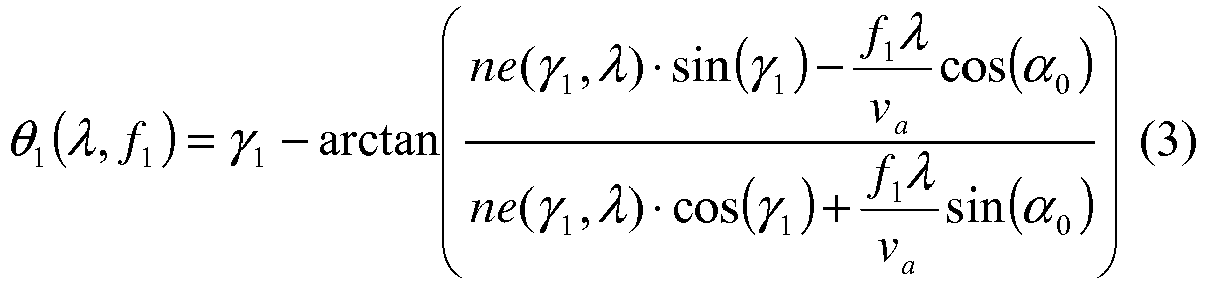
The angular dispersion in this case is also the derivative of the function of (3) with respect to the wavelength λ. The wavelength dependence of the deflection angle θ1 outside thefirst AOD 13 at different acoustic frequencies fi is shown inFig. 5 . The dependence on the wavelength λ is close to linear, whereas the slope dθ/dλ representing the angular dispersion clearly increases with increasing acoustic frequency f1, and increasing deflection angle θ1 as shown infigure 6 . - As mentioned above, in advanced acousto-optic deflection systems the deflection in a given direction (perpendicular to the optical axis Z of the optical system) is realized with two
consecutive AODs beams 18, 18' deflected by bothAODs AODs - There are basically two configurations that can be used in this setup: the
second AOD 14 of the pair is set for the same input and output polarization as thefirst AOD 13. In this case the polarization of the light must be rotated by 90° with a half wave plate between the twoAODs second AOD 14. Moreover, to fulfil the criterion of keeping a point on the same place during focusing, the direction of the acoustic wave in thesecond AOD 14 must be opposite to that in the first. - In the
second AOD 14 theincident beam 18, 18' is already dispersed, so the incidence angle is wavelength dependent and also depends on the acoustic frequency f1 of the first AOD 13 - γ12(λ,f1). If thesecond AOD 14 uses the same configuration as thefirst AOD 13, then equation (3) can be used with the new incidence angles.
- The new incidence angles can be calculated from equation (3) by adding a fix angle δ representing the orientation of the
second AOD 14 with respect to the beam deflected by the first AOD's 13 crystal at a given acoustic frequency f1 taken as the reference - it is usually the centre frequency of the acoustic band.
- In the second configuration the
second AOD 14 operates with 90° rotated incident and output polarization as thefirst AOD 13. Therefore the output polarization of thefirst AOD 13 must not be rotated (the half wave plate can be omitted). Moreover the acoustic wave direction should be the same in thesecond AOD 14 as in thefirst AOD 13, it should not be rotated. The deflection angle θ2 after thesecond AOD 14 can be calculated by solving equation (6). - The angle θ2 can be expressed analytically too, as one of the radicals of the fourth grade equation, but it is complicated. Hence we propose to solve the equation numerically:

- Otherwise the operation of the two setups using different incident polarizations and acousto-optic cell rotations are comparable, and can be described using almost the same physical picture.
- If the optical system is a microscope the deflection angle θ2 is transformed into a focal point position on the target by an optical chain. The last element of this chain is the
microscope objective 16. Conveniently, the position coordinates are defined as the x, y and z distances from an origin. This origin is the point where the objective's 16 optical axis Z intersects the principal focal plane. The deflected beam direction that coincides with this optical axis Z needs to be selected. - The
second AOD 14 also has a central acoustic frequency, usually the center of the working acoustic band. In both setup variations particular acoustic frequencies f1 and f2 can be selected in the twoconsecutive AODs beam 18, 18' deflected twice does not contain angular dispersion after thesecond AOD 14, because thesecond AOD 14 exactly cancels out the dispersion introduced by thefirst AOD 13. This occurs when the frequencies f1 and f2 are nearly equal - The beam without angular dispersion is conveniently set to coincide with the optical axis Z of the optical system subsequent to the
second AOD 14. - The angular dispersion in the
beams 18, 18' diffracted at other acoustic frequencies f1 and f2 in the first andsecond AOD 
- Formally the optical axis z can be found where the right side of equation (7) is equal to zero. With δ=0 and
identical AODs - The visible deflection angles θdef, θdef' outside the
second AOD 14 can be calculated using its wavelength dependent refractive index, which is slightly different in the two cases because of the different polarization states.
- Here λc, fc1, fc2 are the central optical wavelength and acoustic frequencies, respectively, that determine the optical axis Z after the
AODs - By generalization of the angular dispersion compensation method based on a prism 10 it is possible to design the optimized
compensator system 20 that compensates for the above described spatially variable angular dispersion. Thiscompensator system 20 consists of spherical and aspheric lenses and fulfils the following criteria: - It creates the image of the
second AOD 14 of an AOD pair into a given plane: thebeams 18, 18' deflected at different acoustic frequencies will overlap each other in this plane, but each will have different angle of propagation M∗θdef, M∗θdef' at this plane. Ideally this plane coincides with the entrance pupil of themicroscope objective 16 in a microscope system. - The
different wavelength components beam 18 are parallelized as much as possible after thelast lens group 24 of thecompensator system 20, but the angular variation of thebeams 18, 18' deflected at different acoustic frequencies f1, f2 and f1', f2' is maintained. - As discussed above the
compensator system 20 comprises three main parts: thefirst lens group 22 focusing the deflected beams 18, 18' into the focal plane FP of thefirst lens group 22, thecompensator element 26 compensating for the angular dispersion of the deflected beams 18, 18' and thethird lens group 24 parallelizing thespectral components - The
compensator element 26 can be fabricated as a glass piece with afirst surface 26a of radius R1 and asecond surface 26b of radius R2. - As explained before, the
first lens group 22 focuses the deflected beams 18, 18' into its focal plane FP, where the deflected beams 18, 18' are spatially separated, and thewavelength components beam 18 are separated too, but with at least about one order of magnitude less amount, typically by one-two orders of magnitude less amount. Thefirst lens group 22 of focal length foci transforms the deflection angle θdef, θdef' into spatial distance r, r' measured from the optical axis Z in the focal plane FP:
- The angular dispersion into spatial spread of the
spectral components 
- The angular separation of the
spectral components - To compensate effectively for the angular dispersion a prism 10 is the most forehand solution. The amount of angular dispersion, which a prism 10 can compensate for, can be matched to a given dispersion value by properly selecting the incidence angle α1 and the prism opening angle αp. The output angle after the prism is given by:

- The wavelength dependent incidence angle α1 can be determined from the tilt angle β of the prism 10 (i.e. the angle between the optical axis Z and the angle of incidence) and the wavelength dependent angle θdef of propagation:


- The zero angular dispersion requirement after the prism can be expressed as:

- To compensate for an angular dispersion that increases with the distance r from the optical axis Z both the tilt angle β and the prism opening angle αP should be varied: the two functions β(r) and αP(r) can be computed.
- From these relations the nominal radiuses R1 and R2 of the
first surface 26a and of thesecond surface 26b that together work like prisms with varying and matching tilt angles (or incidence angles) and opening angles, can be calculated. - In the first approach, where these
surfaces first surface 26a can be expressed as:
second surface 26b can be expressed as:
- The
optimal surfaces 
- The conic and aspheric parameters (indicated in
Fig. 4 ) are determined by proper optimization. The value of the radius R1, R2, and minimum glass thickness d at the optical axis Z is also determined with optimization using the optimization algorithms of Zemax. Two merit functions are consecutively used, one containing the angular dispersion and aperture before the objective 16 and a second targeting minimum spot size in the sample plane (the focal plane of the objective 16). Iteration of these two leads to optimizedsurfaces compensator element 26 can be made of any highly dispersive glass, e.g. SF10, SF 11 etc. For each material separate optimization is required. - The
second lens group 24 of the setup typically comprises a single lens which accounts for imaging the deflected beams 18, 18' onto the objective's 16 back aperture and for filling the objective aperture at each deflection angle M∗θdef, M∗θdef'. Its focal length and position are also optimized. For example an Olympus scan lens of 210 mm focal length may be used at this place, when thecompensator system 20 is used in combination with a LumPlan 20x Olympus objective. As is clear from the above equations the parameters of thecustom surfaces compensator element 26 can be optimized for a variety of, commercially available lenses preselected for thesecond lens group 24 of theangular compensator system 20. Optimization and analysis must be performed for each combination to give the highest field of view within a given angular resolution range. - When compared with a conventional setup which would use a simple telescopic lens system instead of the
inventive compensator system 20, we have found that using theinventive compensator system 20 it was possible to obtain 700 µm lateral field of view whereas using a conventional telescopic lens system only 420 µm lateral field of view was obtained with the same focused spot size and dispersion at the edges of this area. - It is clear that the same equations can be used to calculate the
surface compensator element 26 in a direction perpendicular to x, say y, if a second pair of AODs are used to deflect thebeams 18, 18' in a lateral direction (y) perpendicular to the deflection direction (x) occasioned by the first pair of AODs 13, 14. - An arrangement similar to that depicted in
Figs 2 and3 can be used to compensate the angular dispersion introduced by asingle deflector deflectors 13, 14 (Figs 6 and7 ) it will be obvious that the dependence is linear in both cases, with certain differences: - 1. in the one deflector case the curve does not pass through the origin, so nonzero angular dispersion is present at all deflection angles
- 2. the slope of the curve is twice in the single deflector case than that in the two-deflector case
- The above-described embodiments are intended only as illustrating examples and are not to be considered as limiting the invention. Various modifications will be apparent to a person skilled in the art without departing from the scope of protection determined by the attached claims.
Claims (11)
- Compensator system (20) adapted to compensate for the angular dispersion of electromagnetic beams (18, 18') deflected by at least one acousto-optic deflector (13, 14) of an optical system, wherein the angular dispersion of each deflected beam (18, 18') is dependent on the deflection angle (θdef, θdef') obtained by the deflecting acoustic frequency (f1, f2, f1', f2') of the acousto-optic deflector (13, 14), characterised in that the compensator system (20) comprises:- a first lens group (22) for spatially separating different wavelength components (18a, 18b, 18c) of deflected beams (18, 18') of different deflection angle (θdef, θdef') by focusing the beams (18, 18') substantially into a focal plane (FP) of the first lens group (22),- a compensator element (26) having a first surface (26a) and a second surface (26b), and being arranged such that the first surface (26a) of the compensator element (26) lies substantially in the focal plane (FP) of the first lens group (22), and the first and second surfaces (26a, 26b) of the compensator element (26) have nominal radiuses R1 and R2 that together work as local prisms with tilt angles β and prism opening angles αp that vary with the distance from the optical axis so as to compensate for the angular dispersion of the spatially separated different wavelength components (18a, 18b, 18c) of each deflected beam (18, 18'),- a second lens group (24) arranged so as to substantially parallelise the different wavelength components (18a, 18b, 18c) of each deflected beam (18, 18') exiting the compensator element (26) while maintaining the angular variation of the beams (18, 18') deflected at different acoustic frequencies (f1, f2, f1', f2').
- The compensator system (20) according to claim 1, wherein the compensator element (26) is adapted to compensate for the angular dispersion of a beam (18, 18') deflected by at least one pair of acousto-optic deflectors (13, 14).
- The compensator system (20) according to claim 2, wherein the compensator element (26) is adapted to compensate for the angular dispersion of a beam (18, 18') deflected by a first pair of acousto-optic deflectors deflecting the beam (18, 18') in a first lateral direction (x) and by a second pair of acousto-optic deflectors deflecting the beam (18, 18') in a second lateral direction (y).
- The compensator system (20) according to any of claims 1 to 3, wherein the first lens group (22) consists of a double lens and the second lens group (24) consists of a single lens.
- Method for compensating for the angular dispersion of electromagnetic beams (18, 18') deflected by at least one acousto-optic deflector (13, 14) of an optical system, wherein the angular dispersion of each deflected beam (18, 18') is dependent on the deflection angle (θdef, θdef') obtained by the deflecting acoustic frequency (f1, f2, f1', f2') characterised by- spatially separating different wavelength components (18a, 18b, 18c) of deflected beams (18, 18') of different deflection angle (θdef, θdef') by focusing the beams (18, 18') via a first lens group (22) substantially into a focal plane (FP) of the first lens group (22),- compensating for the angular dispersion of the spatially separated deflected beam components (18a, 18b, 18c) with local prisms having tilt angles β and prism opening angles αp that vary with the distance from the optical axis so as to compensate for the angular dispersion of the beam component (18a, 18b, 18c) incident at the given location, wherein the local prism are provided in the form of a compensator element (26) having a first surface (26a) and a second surface (26b), and being arranged such that the first surface (26a) of the compensator element (26) lies substantially in the focal plane (FP) of the first lens group (22), and the first and second surfaces (26a, 26b) of the compensator element (26) have nominal radiuses R1 and R2 that together work as the local prisms,- substantially parallelising the spectral components (18a, 18b, 18c) of each deflected beam (18, 18') via a second lens group while maintaining the angular variation of the beams (18, 18') deflected at different acoustic frequencies (f1, f2, f1, f2').
- The method according to claim 5, wherein the beams (18, 18') are deflected by at least a pair of acousto-optic deflectors (13, 14) of the optical system.
- The method according to claim 6, wherein the beams (18, 18') are deflected by a first pair of acousto-optic deflectors deflecting the beam (18, 18') in a first lateral direction (x) and by a second pair of acousto-optic deflectors (13, 14) deflecting the beam in a second lateral direction (y).
- Optical system comprising at least one acousto-optic deflector (13, 14), characterised by comprising a compensator system (20) according to claim 1.
- The optical system according to claim 8, wherein the optical system comprises two consecutive acousto-optic deflectors (13, 14) and a compensator system (20) is arranged after each acousto-optic deflector (13, 14).
- The optical system according to claim 9, wherein the optical system comprises at least a pair of acousto-optic deflectors (13, 14) and the compensator element (26) of the compensator system is adapted to compensate for the angular dispersion of a beam (18, 18') deflected by at least the pair of acousto-optic deflectors (13, 14).
- The optical system according to claim 10, wherein the optical system comprises at least a first pair of acousto-optic deflectors deflecting the beam (18, 18') in a first lateral direction (x) and a second pair of acousto-optic deflectors deflecting the beam (18, 18') in a second lateral direction (y) and the compensator element (26) of the compensator system (20) is adapted to compensate for the angular dispersion of a beam (18, 18') deflected by the first and second acousto-optic deflectors (13, 14).
Applications Claiming Priority (2)
| Application Number | Priority Date | Filing Date | Title |
|---|---|---|---|
| HUP1100727 | 2011-12-28 | ||
| PCT/HU2012/000003 WO2013098568A1 (en) | 2011-12-28 | 2012-01-05 | Compensator system and method for compensating angular dispersion |
Publications (2)
| Publication Number | Publication Date |
|---|---|
| EP2798401A1 EP2798401A1 (en) | 2014-11-05 |
| EP2798401B1 true EP2798401B1 (en) | 2019-10-23 |
Family
ID=89662376
Family Applications (1)
| Application Number | Title | Priority Date | Filing Date |
|---|---|---|---|
| EP12709692.3A Active EP2798401B1 (en) | 2011-12-28 | 2012-01-05 | Compensator system and method for compensating angular dispersion |
Country Status (7)
| Country | Link |
|---|---|
| US (1) | US9535309B2 (en) |
| EP (1) | EP2798401B1 (en) |
| JP (1) | JP5890536B2 (en) |
| CN (1) | CN104115062B (en) |
| CA (1) | CA2861716C (en) |
| HU (1) | HUE047252T2 (en) |
| WO (1) | WO2013098568A1 (en) |
Families Citing this family (19)
| Publication number | Priority date | Publication date | Assignee | Title |
|---|---|---|---|---|
| CN104391370B (en) * | 2014-11-04 | 2017-09-12 | 温州生物材料与工程研究所 | The imaging converting system of flat field scanning lens working face and surgical operation microscope working face |
| CN104600555B (en) * | 2015-01-21 | 2017-10-17 | 中国航空工业集团公司北京长城计量测试技术研究所 | Dynamic sound-light modulates the system of selection of optical frequency level and device |
| CN104849837B (en) * | 2015-05-04 | 2017-03-01 | 华中科技大学 | A kind of dispersion compensation device |
| US10313211B1 (en) * | 2015-08-25 | 2019-06-04 | Avi Networks | Distributed network service risk monitoring and scoring |
| US10250452B2 (en) * | 2015-12-14 | 2019-04-02 | Microsoft Technology Licensing, Llc | Packaging tool for first and third party component deployment |
| CN105589209B (en) * | 2016-03-22 | 2018-10-23 | 武汉理工大学 | A kind of dispersion compensation device |
| CN110799899B (en) * | 2017-07-03 | 2024-04-23 | 伊雷克托科学工业股份有限公司 | Acousto-optic device via optical contact and method for manufacturing the same |
| US11439369B1 (en) | 2017-10-26 | 2022-09-13 | United States Of America As Represented By The Secretary Of The Air Force | Method and apparatus for imaging with reduced level of off-axis artifacts |
| WO2020007761A1 (en) * | 2018-07-02 | 2020-01-09 | Universitat De Barcelona | Programmable multiple-point illuminator, confocal filter, confocal microscope and method to operate said confocal microscope |
| US11033981B2 (en) * | 2018-07-23 | 2021-06-15 | University Of Maryland, College Park | Acousto-optic modulator configurations for quantum processing |
| CN109307930B (en) * | 2018-11-05 | 2023-09-12 | 中国科学院苏州生物医学工程技术研究所 | Two-photon microscope for two-dimensional high-speed scanning imaging by adopting two acousto-optic deflectors with different sound speeds |
| CN112433353A (en) * | 2020-09-30 | 2021-03-02 | 天津大学 | Optical time domain extending device based on prism refraction dispersion |
| CN112540459B (en) * | 2020-11-27 | 2022-05-13 | 中国科学院深圳先进技术研究院 | Optimization adjustment method of double-prism dispersion device |
| WO2023146631A1 (en) * | 2022-01-28 | 2023-08-03 | Electro Scientific Industries, Inc. | Germanium aod system with parallel and perpendicular orientations |
| US12276897B2 (en) * | 2022-09-06 | 2025-04-15 | Orbotech Ltd. | Dynamic correction for an acousto-optic deflector |
| CN115629469B (en) * | 2022-09-22 | 2025-10-17 | 中国科学院长春光学精密机械与物理研究所 | Large telescope racemization and achromatism control method and system |
| US20240152022A1 (en) * | 2022-11-04 | 2024-05-09 | Orbotech Ltd. | Passive dispersion compensation for an acousto-optic deflector |
| CN118940424B (en) * | 2024-06-24 | 2025-10-10 | 北京理工大学 | Universal partial compensator design method and device for use with sub-aperture stitching |
| CN119335790B (en) * | 2024-12-04 | 2025-09-05 | 华中科技大学 | A dispersion compensation method for an acousto-optic deflector based on a dispersion prism group |
Family Cites Families (7)
| Publication number | Priority date | Publication date | Assignee | Title |
|---|---|---|---|---|
| DE19805111A1 (en) | 1998-02-09 | 1999-08-19 | Ldt Gmbh & Co | Distraction device, its use and a video system |
| WO2006042130A2 (en) * | 2004-10-06 | 2006-04-20 | Baylor College Of Medicine | High speed microscope with three-dimensional laser beam scanning |
| GB0617945D0 (en) * | 2006-09-12 | 2006-10-18 | Ucl Business Plc | Imaging apparatus and methods |
| JP5101393B2 (en) | 2008-05-26 | 2012-12-19 | オリンパス株式会社 | Laser microscope |
| HU0800781D0 (en) | 2008-12-31 | 2009-03-02 | Femtonics Kft | Focusing system comprising acousto-optic deflectors for focusing an electromagnetic beam |
| CN101706617B (en) * | 2009-09-30 | 2011-11-02 | 深圳先进技术研究院 | Acousto-optic filter |
| CN101887201B (en) * | 2010-06-29 | 2013-06-05 | 中国科学院深圳先进技术研究院 | Wavelength selecting device |
-
2012
- 2012-01-05 CA CA2861716A patent/CA2861716C/en active Active
- 2012-01-05 WO PCT/HU2012/000003 patent/WO2013098568A1/en not_active Ceased
- 2012-01-05 HU HUE12709692A patent/HUE047252T2/en unknown
- 2012-01-05 JP JP2014549539A patent/JP5890536B2/en active Active
- 2012-01-05 US US14/368,937 patent/US9535309B2/en active Active
- 2012-01-05 CN CN201280069977.8A patent/CN104115062B/en active Active
- 2012-01-05 EP EP12709692.3A patent/EP2798401B1/en active Active
Non-Patent Citations (1)
| Title |
|---|
| SHAOQUN ZENG ET AL: "Analysis of the dispersion compensation of acousto-optic deflectors used for multiphoton imaging", JOURNAL OF BIOMEDICAL OPTICS, vol. 12, no. 2, 1 January 2007 (2007-01-01), pages 024015, XP055577254, ISSN: 1083-3668, DOI: 10.1117/1.2714061 * |
Also Published As
| Publication number | Publication date |
|---|---|
| EP2798401A1 (en) | 2014-11-05 |
| US20150029578A1 (en) | 2015-01-29 |
| CN104115062A (en) | 2014-10-22 |
| US9535309B2 (en) | 2017-01-03 |
| CA2861716A1 (en) | 2013-07-04 |
| JP2015507766A (en) | 2015-03-12 |
| CA2861716C (en) | 2019-05-14 |
| CN104115062B (en) | 2016-12-14 |
| HUE047252T2 (en) | 2020-04-28 |
| JP5890536B2 (en) | 2016-03-22 |
| WO2013098568A1 (en) | 2013-07-04 |
Similar Documents
| Publication | Publication Date | Title |
|---|---|---|
| US9535309B2 (en) | Compensator system and method for compensating angular dispersion | |
| US9104087B2 (en) | Imaging apparatus and methods | |
| US10194788B2 (en) | Optical scanner and scanned lens optical probe | |
| US20030230710A1 (en) | Microscope, particularly a laser scanning microscope with adaptive optical arrangement | |
| US20130229654A1 (en) | Illumination optical system, light irradiation apparatus for spectrometory, and spectometer | |
| US10551606B2 (en) | Light-scanning microscope with simplified optical system, more particularly with variable pupil position | |
| EP2800995B1 (en) | Method for scanning along a continuous scanning trajectory with a scanner system | |
| KR20000068681A (en) | Microscope with adaptive optics system | |
| US8098374B2 (en) | Highly sensitive spectroscopic unit | |
| EP2442316A1 (en) | Method and apparatus for measuring the optical forces acting on a particle | |
| US20130229653A1 (en) | Spectrometric optical system and spectrometer | |
| JPH11119106A (en) | Laser scanning microscope | |
| WO2019187422A1 (en) | Distance measurement unit and light irradiation device | |
| EP3193207A1 (en) | Light irradiating device and light irradiating method | |
| JP2022512143A (en) | Equipment and methods for light beam scanning microspectroscopy | |
| US7385693B2 (en) | Microscope apparatus | |
| CN111630432B (en) | Sound and light devices and methods | |
| US20230030757A1 (en) | Formation of a beam with a flat-top profile and elongated cross-section and use of same | |
| CN112567281A (en) | Illumination assembly for a microscope, microscope and method for illuminating a sample space in a microscope | |
| JPH10318924A (en) | Optical apparatus with pulse laser | |
| US10040146B2 (en) | Integrated single grating compressor for variable pulse-front tilt in simultaneously spatially and temporally focused systems | |
| JP4895519B2 (en) | Microscope equipment | |
| Voloshinov et al. | Compensation for chromatic aberrations in acousto-optic systems used in spectral analysis of images | |
| CN101620355A (en) | Image point focusing method for four wave mixing technology | |
| HU231741B1 (en) | Method for area scanning with a multi-photon laser scanning microscope |
Legal Events
| Date | Code | Title | Description |
|---|---|---|---|
| PUAI | Public reference made under article 153(3) epc to a published international application that has entered the european phase |
Free format text: ORIGINAL CODE: 0009012 |
|
| 17P | Request for examination filed |
Effective date: 20140724 |
|
| AK | Designated contracting states |
Kind code of ref document: A1 Designated state(s): AL AT BE BG CH CY CZ DE DK EE ES FI FR GB GR HR HU IE IS IT LI LT LU LV MC MK MT NL NO PL PT RO RS SE SI SK SM TR |
|
| DAX | Request for extension of the european patent (deleted) | ||
| STAA | Information on the status of an ep patent application or granted ep patent |
Free format text: STATUS: EXAMINATION IS IN PROGRESS |
|
| 17Q | First examination report despatched |
Effective date: 20180511 |
|
| GRAP | Despatch of communication of intention to grant a patent |
Free format text: ORIGINAL CODE: EPIDOSNIGR1 |
|
| STAA | Information on the status of an ep patent application or granted ep patent |
Free format text: STATUS: GRANT OF PATENT IS INTENDED |
|
| INTG | Intention to grant announced |
Effective date: 20190507 |
|
| GRAS | Grant fee paid |
Free format text: ORIGINAL CODE: EPIDOSNIGR3 |
|
| GRAA | (expected) grant |
Free format text: ORIGINAL CODE: 0009210 |
|
| STAA | Information on the status of an ep patent application or granted ep patent |
Free format text: STATUS: THE PATENT HAS BEEN GRANTED |
|
| AK | Designated contracting states |
Kind code of ref document: B1 Designated state(s): AL AT BE BG CH CY CZ DE DK EE ES FI FR GB GR HR HU IE IS IT LI LT LU LV MC MK MT NL NO PL PT RO RS SE SI SK SM TR |
|
| REG | Reference to a national code |
Ref country code: GB Ref legal event code: FG4D |
|
| REG | Reference to a national code |
Ref country code: CH Ref legal event code: EP |
|
| REG | Reference to a national code |
Ref country code: IE Ref legal event code: FG4D |
|
| REG | Reference to a national code |
Ref country code: DE Ref legal event code: R096 Ref document number: 602012065055 Country of ref document: DE |
|
| REG | Reference to a national code |
Ref country code: AT Ref legal event code: REF Ref document number: 1194326 Country of ref document: AT Kind code of ref document: T Effective date: 20191115 |
|
| REG | Reference to a national code |
Ref country code: NL Ref legal event code: MP Effective date: 20191023 |
|
| REG | Reference to a national code |
Ref country code: LT Ref legal event code: MG4D |
|
| REG | Reference to a national code |
Ref country code: HU Ref legal event code: AG4A Ref document number: E047252 Country of ref document: HU |
|
| PG25 | Lapsed in a contracting state [announced via postgrant information from national office to epo] |
Ref country code: PL Free format text: LAPSE BECAUSE OF FAILURE TO SUBMIT A TRANSLATION OF THE DESCRIPTION OR TO PAY THE FEE WITHIN THE PRESCRIBED TIME-LIMIT Effective date: 20191023 Ref country code: NO Free format text: LAPSE BECAUSE OF FAILURE TO SUBMIT A TRANSLATION OF THE DESCRIPTION OR TO PAY THE FEE WITHIN THE PRESCRIBED TIME-LIMIT Effective date: 20200123 Ref country code: LT Free format text: LAPSE BECAUSE OF FAILURE TO SUBMIT A TRANSLATION OF THE DESCRIPTION OR TO PAY THE FEE WITHIN THE PRESCRIBED TIME-LIMIT Effective date: 20191023 Ref country code: GR Free format text: LAPSE BECAUSE OF FAILURE TO SUBMIT A TRANSLATION OF THE DESCRIPTION OR TO PAY THE FEE WITHIN THE PRESCRIBED TIME-LIMIT Effective date: 20200124 Ref country code: ES Free format text: LAPSE BECAUSE OF FAILURE TO SUBMIT A TRANSLATION OF THE DESCRIPTION OR TO PAY THE FEE WITHIN THE PRESCRIBED TIME-LIMIT Effective date: 20191023 Ref country code: NL Free format text: LAPSE BECAUSE OF FAILURE TO SUBMIT A TRANSLATION OF THE DESCRIPTION OR TO PAY THE FEE WITHIN THE PRESCRIBED TIME-LIMIT Effective date: 20191023 Ref country code: LV Free format text: LAPSE BECAUSE OF FAILURE TO SUBMIT A TRANSLATION OF THE DESCRIPTION OR TO PAY THE FEE WITHIN THE PRESCRIBED TIME-LIMIT Effective date: 20191023 Ref country code: FI Free format text: LAPSE BECAUSE OF FAILURE TO SUBMIT A TRANSLATION OF THE DESCRIPTION OR TO PAY THE FEE WITHIN THE PRESCRIBED TIME-LIMIT Effective date: 20191023 Ref country code: PT Free format text: LAPSE BECAUSE OF FAILURE TO SUBMIT A TRANSLATION OF THE DESCRIPTION OR TO PAY THE FEE WITHIN THE PRESCRIBED TIME-LIMIT Effective date: 20200224 Ref country code: BG Free format text: LAPSE BECAUSE OF FAILURE TO SUBMIT A TRANSLATION OF THE DESCRIPTION OR TO PAY THE FEE WITHIN THE PRESCRIBED TIME-LIMIT Effective date: 20200123 Ref country code: SE Free format text: LAPSE BECAUSE OF FAILURE TO SUBMIT A TRANSLATION OF THE DESCRIPTION OR TO PAY THE FEE WITHIN THE PRESCRIBED TIME-LIMIT Effective date: 20191023 |
|
| PG25 | Lapsed in a contracting state [announced via postgrant information from national office to epo] |
Ref country code: RS Free format text: LAPSE BECAUSE OF FAILURE TO SUBMIT A TRANSLATION OF THE DESCRIPTION OR TO PAY THE FEE WITHIN THE PRESCRIBED TIME-LIMIT Effective date: 20191023 Ref country code: IS Free format text: LAPSE BECAUSE OF FAILURE TO SUBMIT A TRANSLATION OF THE DESCRIPTION OR TO PAY THE FEE WITHIN THE PRESCRIBED TIME-LIMIT Effective date: 20200224 Ref country code: HR Free format text: LAPSE BECAUSE OF FAILURE TO SUBMIT A TRANSLATION OF THE DESCRIPTION OR TO PAY THE FEE WITHIN THE PRESCRIBED TIME-LIMIT Effective date: 20191023 |
|
| PG25 | Lapsed in a contracting state [announced via postgrant information from national office to epo] |
Ref country code: AL Free format text: LAPSE BECAUSE OF FAILURE TO SUBMIT A TRANSLATION OF THE DESCRIPTION OR TO PAY THE FEE WITHIN THE PRESCRIBED TIME-LIMIT Effective date: 20191023 |
|
| REG | Reference to a national code |
Ref country code: DE Ref legal event code: R097 Ref document number: 602012065055 Country of ref document: DE |
|
| PG2D | Information on lapse in contracting state deleted |
Ref country code: IS |
|
| PG25 | Lapsed in a contracting state [announced via postgrant information from national office to epo] |
Ref country code: DK Free format text: LAPSE BECAUSE OF FAILURE TO SUBMIT A TRANSLATION OF THE DESCRIPTION OR TO PAY THE FEE WITHIN THE PRESCRIBED TIME-LIMIT Effective date: 20191023 Ref country code: CZ Free format text: LAPSE BECAUSE OF FAILURE TO SUBMIT A TRANSLATION OF THE DESCRIPTION OR TO PAY THE FEE WITHIN THE PRESCRIBED TIME-LIMIT Effective date: 20191023 Ref country code: RO Free format text: LAPSE BECAUSE OF FAILURE TO SUBMIT A TRANSLATION OF THE DESCRIPTION OR TO PAY THE FEE WITHIN THE PRESCRIBED TIME-LIMIT Effective date: 20191023 Ref country code: EE Free format text: LAPSE BECAUSE OF FAILURE TO SUBMIT A TRANSLATION OF THE DESCRIPTION OR TO PAY THE FEE WITHIN THE PRESCRIBED TIME-LIMIT Effective date: 20191023 Ref country code: IS Free format text: LAPSE BECAUSE OF FAILURE TO SUBMIT A TRANSLATION OF THE DESCRIPTION OR TO PAY THE FEE WITHIN THE PRESCRIBED TIME-LIMIT Effective date: 20200223 |
|
| REG | Reference to a national code |
Ref country code: AT Ref legal event code: MK05 Ref document number: 1194326 Country of ref document: AT Kind code of ref document: T Effective date: 20191023 |
|
| PLBE | No opposition filed within time limit |
Free format text: ORIGINAL CODE: 0009261 |
|
| STAA | Information on the status of an ep patent application or granted ep patent |
Free format text: STATUS: NO OPPOSITION FILED WITHIN TIME LIMIT |
|
| PG25 | Lapsed in a contracting state [announced via postgrant information from national office to epo] |
Ref country code: SK Free format text: LAPSE BECAUSE OF FAILURE TO SUBMIT A TRANSLATION OF THE DESCRIPTION OR TO PAY THE FEE WITHIN THE PRESCRIBED TIME-LIMIT Effective date: 20191023 Ref country code: MC Free format text: LAPSE BECAUSE OF FAILURE TO SUBMIT A TRANSLATION OF THE DESCRIPTION OR TO PAY THE FEE WITHIN THE PRESCRIBED TIME-LIMIT Effective date: 20191023 Ref country code: SM Free format text: LAPSE BECAUSE OF FAILURE TO SUBMIT A TRANSLATION OF THE DESCRIPTION OR TO PAY THE FEE WITHIN THE PRESCRIBED TIME-LIMIT Effective date: 20191023 Ref country code: IT Free format text: LAPSE BECAUSE OF FAILURE TO SUBMIT A TRANSLATION OF THE DESCRIPTION OR TO PAY THE FEE WITHIN THE PRESCRIBED TIME-LIMIT Effective date: 20191023 |
|
| REG | Reference to a national code |
Ref country code: CH Ref legal event code: PL |
|
| 26N | No opposition filed |
Effective date: 20200724 |
|
| REG | Reference to a national code |
Ref country code: BE Ref legal event code: MM Effective date: 20200131 |
|
| PG25 | Lapsed in a contracting state [announced via postgrant information from national office to epo] |
Ref country code: LU Free format text: LAPSE BECAUSE OF NON-PAYMENT OF DUE FEES Effective date: 20200105 |
|
| PG25 | Lapsed in a contracting state [announced via postgrant information from national office to epo] |
Ref country code: AT Free format text: LAPSE BECAUSE OF FAILURE TO SUBMIT A TRANSLATION OF THE DESCRIPTION OR TO PAY THE FEE WITHIN THE PRESCRIBED TIME-LIMIT Effective date: 20191023 Ref country code: BE Free format text: LAPSE BECAUSE OF NON-PAYMENT OF DUE FEES Effective date: 20200131 Ref country code: SI Free format text: LAPSE BECAUSE OF FAILURE TO SUBMIT A TRANSLATION OF THE DESCRIPTION OR TO PAY THE FEE WITHIN THE PRESCRIBED TIME-LIMIT Effective date: 20191023 Ref country code: LI Free format text: LAPSE BECAUSE OF NON-PAYMENT OF DUE FEES Effective date: 20200131 Ref country code: CH Free format text: LAPSE BECAUSE OF NON-PAYMENT OF DUE FEES Effective date: 20200131 |
|
| PG25 | Lapsed in a contracting state [announced via postgrant information from national office to epo] |
Ref country code: IE Free format text: LAPSE BECAUSE OF NON-PAYMENT OF DUE FEES Effective date: 20200105 |
|
| PG25 | Lapsed in a contracting state [announced via postgrant information from national office to epo] |
Ref country code: TR Free format text: LAPSE BECAUSE OF FAILURE TO SUBMIT A TRANSLATION OF THE DESCRIPTION OR TO PAY THE FEE WITHIN THE PRESCRIBED TIME-LIMIT Effective date: 20191023 Ref country code: MT Free format text: LAPSE BECAUSE OF FAILURE TO SUBMIT A TRANSLATION OF THE DESCRIPTION OR TO PAY THE FEE WITHIN THE PRESCRIBED TIME-LIMIT Effective date: 20191023 Ref country code: CY Free format text: LAPSE BECAUSE OF FAILURE TO SUBMIT A TRANSLATION OF THE DESCRIPTION OR TO PAY THE FEE WITHIN THE PRESCRIBED TIME-LIMIT Effective date: 20191023 |
|
| PG25 | Lapsed in a contracting state [announced via postgrant information from national office to epo] |
Ref country code: MK Free format text: LAPSE BECAUSE OF FAILURE TO SUBMIT A TRANSLATION OF THE DESCRIPTION OR TO PAY THE FEE WITHIN THE PRESCRIBED TIME-LIMIT Effective date: 20191023 |
|
| P01 | Opt-out of the competence of the unified patent court (upc) registered |
Effective date: 20230529 |
|
| PGFP | Annual fee paid to national office [announced via postgrant information from national office to epo] |
Ref country code: DE Payment date: 20250121 Year of fee payment: 14 |
|
| PGFP | Annual fee paid to national office [announced via postgrant information from national office to epo] |
Ref country code: FR Payment date: 20250127 Year of fee payment: 14 |
|
| PGFP | Annual fee paid to national office [announced via postgrant information from national office to epo] |
Ref country code: GB Payment date: 20250128 Year of fee payment: 14 |
|
| PGFP | Annual fee paid to national office [announced via postgrant information from national office to epo] |
Ref country code: HU Payment date: 20250404 Year of fee payment: 14 |